Embed Size (px)
Citation preview
IRIDEX Cyclo G6™ Laser System
Operator Manual

IRIDEX Cyclo G6™ Laser System Operator Manual
66294-EN Rev D 2018
© 2018 by IRIDEX Corporation. All rights reserved.
IRIDEX, the IRIDEX logo, IRIS Medical, MicroPulse, and SmartKey are registered trademarks; CW-Pulse, FiberCheck, FlexFiber, G-Probe, Cyclo G6, LongPulse, MilliPulse, PowerStep, are trademarks of IRIDEX
Corporation. All other trademarks are the property of their respective holders.

66294-EN Rev D iii
Contents
1 Introduction ............................................................................................................. 1
Compatible Delivery Devices ............................................................................................. 1
Pulse Types ......................................................................................................................... 2
References ........................................................................................................................... 4
Indication for Use ............................................................................................................... 5
References ........................................................................................................................... 7
Warnings and Cautions ....................................................................................................... 8
IRIDEX Corporation Contact Information ......................................................................... 9
2 Setup ....................................................................................................................... 10
Unpacking the System ...................................................................................................... 10
Choosing a Location ......................................................................................................... 11
Connecting the Components ............................................................................................. 11
3 Operation ............................................................................................................... 13
Front Panel Controls ......................................................................................................... 13
Powering the Laser On and Off ........................................................................................ 13
Treating Patients ............................................................................................................... 14
Using the Laser System .................................................................................................... 15
4 Troubleshooting .................................................................................................... 22
General Problems .............................................................................................................. 22
Error Messages ................................................................................................................. 23
5 Maintenance .......................................................................................................... 25
Inspecting and Cleaning the Laser .................................................................................... 25
Inspecting and Cleaning the Footswitch ........................................................................... 25
Verifying the Power Calibration ....................................................................................... 25
6 Safety and Compliance ......................................................................................... 28
Protection for the Physician .............................................................................................. 28
Protection for All Treatment Room Personnel .................................................................. 28
Safety Compliance ............................................................................................................ 30
Labels ................................................................................................................................ 31
Symbols (As Applicable) .................................................................................................. 33
Specifications .................................................................................................................... 35
7 Wireless Footswitch and EMC ............................................................................ 36
Setting Up the Wireless Footswitch .................................................................................. 36
Testing the Batteries ......................................................................................................... 36
EMC Safety Information ................................................................................................... 37
EMC Requirements for Console and Accessories ............................................................ 38

iv 66294-EN Rev D
Contents
66294-EN Rev D Introduction 1
1 Introduction
The IRIDEX Cyclo G6™ Laser System is a semiconductor diode laser that delivers true continuous wave
infrared (810 nm) laser light for ophthalmic applications. Improper use of the laser system can result in adverse
effects. Follow the instructions for use described in this operator manual.
Compatible Delivery Devices These IRIDEX Families of Probe Delivery Devices are compatible with the Cyclo G6 laser system:
• MicroPulse® Family
– MicroPulse P3: A single-use, RFID, fiber-optic handheld delivery device that when used with the
Cyclo G6, transmits 810 nm MicroPulse laser energy transsclerally to the ciliary processes for the treatment
of glaucoma. The fiber-optic tip of the MicroPulse P3 is 600-μm diameters and protrudes 0.4 mm from the
handpiece which allows accurate positioning of the fiber-optic tip at 3 mm posterior to the limbus.
– The MicroPulse Family may also include additional probes.
• G-Probe™ Family
– G-Probe: A single-use, RFID, fiber-optic handheld delivery device that when used with the Cyclo G6,
transmits continuous-wave infrared laser transsclerally to the ciliary processes for the treatment of
glaucoma. The fiber-optic tip of the G-Probe is 600-μm diameter and protrudes 0.7 mm from the
handpiece which allows accurate positioning of the fiber-optic tip at 1.2mm posterior to the limbus.
– G-Probe™ Illuminate: Identical to the G-Probe with the addition of transillumination.
Transillumination aids the physician in identifying the location of the ciliary processes.
– The G-Probe Family may also include additional probes.
NOTE: Refer to the appropriate delivery device “Instructions For Use” for indications for use,
contraindications, precautions, and adverse effects information.
Illumination Control and Light Regulation
The IRIDEX Cyclo G6 Laser System includes a white light illumination source for augmenting visualization of
target tissue during treatment. Compatible delivery devices, such as G-Probe Illuminate, contain illumination
fibers for carrying white light from the console to the distal tip of the device. The light source is a white (broad
spectrum) LED that is driven from 0 – 5 mW; the power level (and therefore the amount of illumination) is
adjustable by the user via the touch screen interface on the console and remote control. Power to the white LED
is normally OFF; power ON is managed automatically by the console when a compatible connector is inserted
into the light source orifice. An optical microswitch in the light source orifice detects proximity of a compatible
connector and triggers the ON/OFF function of the illumination source.
2 IRIDEX Cyclo G6™ Laser System Operator Manual 66294-EN Rev D
Pulse Types
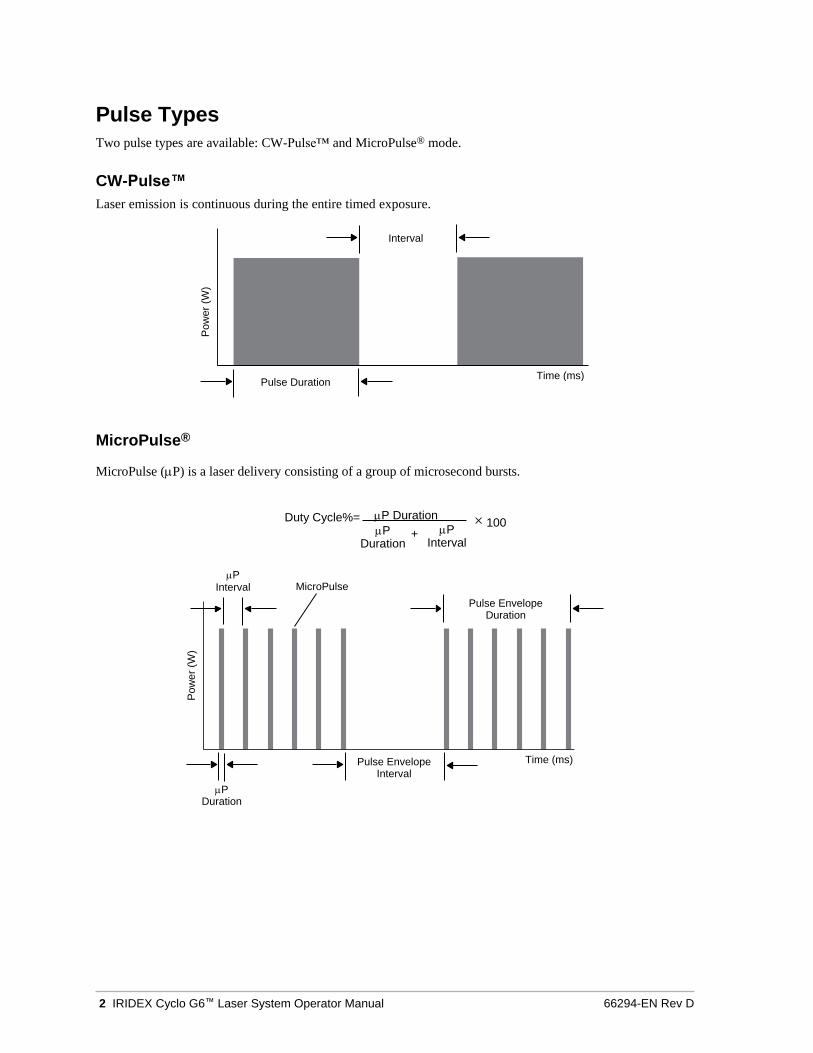
Two pulse types are available: CW-Pulse™ and MicroPulse® mode.
CW-Pulse™
Laser emission is continuous during the entire timed exposure.
MicroPulse®
MicroPulse (P) is a laser delivery consisting of a group of microsecond bursts.
Duty Cycle%= P Duration × 100
P + Duration
P Interval
P Interval MicroPulse
Pulse Envelope Duration
P Duration
Pulse Envelope Interval
Time (ms)
Interval
Pulse Duration Time (ms)
Pow
er
(W)
Pow
er
(W)
66294-EN Rev D Introduction 3
MicroPulse® is typically used to administer subvisible threshold laser treatments to macular and perimacular
targets. When used here, the terms “subvisible”, “subvisible threshold” or “subthreshold” denote that the desired
endpoint is one in which treated tissue offers no ophthalmoscopically observable laser effects. Nevertheless,
studies using 810 nm lasers have confirmed that subvisible laser treatment strategies can be clinically effective
while inducing no changes discernible by slit lamp observation, fluorescein angiography (FA), fundus
autofluorescence (FAF), or at any time postoperatively.1,2
Tissues receiving subvisible MicroPulse® laser treatment show no such changes because:
• MicroPulse® laser delivery is being used instead of CW, and
• The total laser energy of such doses is only a percentage (often chosen by clinicians to be 20-70%) of that
energy needed to produce a visible endpoint.
Energy (J) is equal to [Laser Power (W)] × [Exposure Duration(s)] × [Duty Factor (%/100)]. Duty Factor is often
5% to 15% when using MicroPulse® mode, and is 100% when using CW mode. Clinicians have reported various
strategies to adjust these parameters relative to suprathreshold burns in order to achieve clinically effective
subvisible endpoints.1-4
Additional parameters to consider in any laser treatment protocol, and particularly during MicroPulse®, is
spacing between laser treatment spots, and the total number of treatment spots administered. Due to the limited
thermal spread of MicroPulse® exposures, subvisible treatments often call for the administration of a greater
number of treatment spots with denser spacing than that used for threshold laser grid treatments.4
4 IRIDEX Cyclo G6™ Laser System Operator Manual 66294-EN Rev D
References
1. Sasoh M, Smiddy W: Diode Laser Endophotocoagulation. Retina 1995;15(5):388-393.
2. Akduman, L, Olk, RJ: Diode Laser (810 Nm) Versus Argon Green (514 Nm) Modified Grid Photocoagulation
for Diffuse Diabetic Macular Edema. Ophthalmology 1997;104(9):1433-41.
3. Ulbig MW, McHugh DA, Hamilton AM: Diode Laser Photocoagulation for Diabetic Macular Oedema.
Br J Ophthalmol 1995;79(4):318-21.
4. Luttrull JK, Sramek C, Palanker D, Spink CJ, Musch DC: Long-Term Safety, High-Resolution Imaging, and
Tissue Temperature Modeling of Subvisible Diode Micropulse Photocoagulation for Retinovascular Macular
Edema. Retina 2012;32(2):375-86.
5. Vujosevic S, Bottega E, Casciano M, Pilotto E, Convento E, Midena E: Microperimetry and Fundus
Autofluorescence in Diabetic Macular Edema: Subthreshold Micropulse Diode Laser Versus Modified Early
Treatment Diabetic Retinopathy Study Laser Photocoagulation. Retina 2010;30(6):908-916.
6. Agarwal HC, Poovali S, Sihota R, Dada T: Comparative Evaluation of Diode Laser Trabeculoplasty Vs.
Frequency Doubled Nd : Yag Laser Trabeculoplasty in Primary Open Angle Glaucoma. Eye 2006;20(12):1352-6.
7. Chung PY, Schuman JS, Netland PA, Lloyd-Muhammad RA, Jacobs DS: Five-Year Results of a Randomized,
Prospective, Clinical Trial of Diode Vs Argon Laser Trabeculoplasty for Open-Angle Glaucoma.
Am J Ophthalmol 1998;126(2):185-90.
8. Panarelli, JF, Banitt, MR, Sidoti, PA: Transscleral Diode Laser Cyclophotocoagulation after Baerveldt
Glaucoma Implant Surgery. J Glaucoma 2012.
9. Wilensky, JT, Kammer, J: Long-Term Visual Outcome of Transscleral Laser Cyclotherapy in Eyes with
Ambulatory Vision. Ophthalmology 2004;111(7):1389-92.
10. Schlote T, Derse M, Rassmann K, Nicaeus T, Dietz K, Thiel HJ: Efficacy and Safety of Contact Transscleral
Diode Laser Cyclophotocoagulation for Advanced Glaucoma. J Glaucoma 2001;10(4):294-301.
11. Haller JA, Blair N, de Juan E Jr, De Bustros S, Goldberg MF, Muldoon T, Packo K, Resnick K, Rosen R,
Shapiro M, Smiddy W, Walsh J: Transscleral Diode Laser Retinopexy in Retinal Detachment Surgery: Results
of a Multicenter Trial. Retina 1998;18(5):399-404.
12. Kapran Z, Uyar OM, Bilgin BA, Kaya V, Cilsim S, Eltutar K: Diode Laser Transscleral Retinopexy in
Rhegmatogenous Retinal Detachment Surgery. Eur J Ophthalmol 2001;11(4):356-60.
13. Odergren, A, Algvere, PV, Seregard, S, Kvanta, A: A Prospective Randomised Study on Low-Dose
Transpupillary Thermotherapy Versus Photodynamic Therapy for Neovascular Age-Related Macular
Degeneration. Br J Ophthalmol 2008;92(6):757-61.
14. Sharma, T, Krishnan, T, Gopal, L, Nagpal, A, Khetan, V, Rishi, P: Transpupillary Thermotherapy for
Circumscribed Choroidal Hemangioma: Clinical Profile and Treatment Outcome. Ophthalmic Surg Lasers
Imaging 2011;42(5):360-8.
15. Shields CL, Shields JA, Perez N, Singh AD, Cater J: Primary Transpupillary Thermotherapy for Small Choroidal
Melanoma in 256 Consecutive Cases: Outcomes and Limitations. Ophthalmology 2002;109(2):225-34.
16. Banach, MJ, Berinstein, DM: Laser Therapy for Retinopathy of Prematurity. Curr Opin Ophthalmol
2001;12(3):164-70.
17. Axer-Siegel, R, Snir, M, Cotlear, D, Maayan, A, Frilling, R, Rosenbaltt, I, Weinberger, D, Kremer, I, Sirota, L:
Diode Laser Treatment of Posterior Retinopathy of Prematurity. Br J Ophthalmol 2000;84(12):1383-6.
18. Manayath, GJ, Narendran, V, Arora, S, Morris, RJ, Saravanan, VR, Shah, PK: Graded Subthreshold
Transpupillary Thermotherapy for Chronic Central Serous Chorioretinopathy. Ophthalmic Surg Lasers
Imaging 2012;43(4):284-90.
19. Chen SN, Hwang JF, Tseng LF, Lin CJ: Subthreshold Diode Micropulse Photocoagulation for the Treatment
of Chronic Central Serous Chorioretinopathy with Juxtafoveal Leakage. Ophthalmology 2008;115(12):2229-34.
20. Lanzetta P, Furlan F, Morgante L, Veritti D, Bandello F: Nonvisible Subthreshold Micropulse Diode Laser (810
Nm) Treatment of Central Serous Chorioretinopathy. A Pilot Study. Eur J Ophthalmol 2008;18(6):934-40.
21. Koss MJ, Beger I, Koch FH: Subthreshold Diode Laser Micropulse Photocoagulation Versus Intravitreal
Injections of Bevacizumab in the Treatment of Central Serous Chorioretinopathy. Eye (Lond) 2012;26(2):307-14.
22. Parodi MB, Spasse S, Iacono P, Di Stefano G, Canziani T, Ravalico G: Subthreshold Grid Laser Treatment of
Macular Edema Secondary to Branch Retinal Vein Occlusion with Micropulse Infrared (810 Nanometer) Diode
Laser. Ophthalmology 2006;113(12):2237-42.
66294-EN Rev D Introduction 5
Indication for Use
This section provides information on the use of the laser in clinical specialties. Information is provided by
specialty and includes procedural recommendations along with specific indications and contraindications. This
information is not intended to be all-inclusive and is not intended to replace surgeon training or experience. The
regulatory information provided is applicable only in the United States. If the laser is used for indications not
included herein, the user will be subject to 21 CFR Part 812, the Food and Drug Administration’s Investigational
Device Exemption (IDE) regulations. For information regarding the regulatory status of indications other than
those listed in this manual, contact IRIDEX Regulatory Affairs.
IRIDEX does not make recommendations regarding the practice of medicine. References in literature are
provided as a guide. Individual treatment should be based on clinical training, clinical observation of laser tissue
interaction, and appropriate clinical endpoints.
Indication for Use
The Family of IRIDEX IQ Laser Systems (IQ 532 [532nm], IQ 577 [577nm], IQ 630-670 [630nm-670nm],
IQ 810 [810nm] [IRIDEX Cyclo G6 Laser System]) and the hand pieces, delivery devices & accessories that are
used with them to deliver laser energy in either CW-pulse, MicroPulse® or LongPulse™ mode. Intended for soft
and fibrous tissue, including osseous tissue incision, excision, coagulation, vaporization, ablation and vessel
hemostasis in the medical specialties of, dermatology, ear, nose and throat (ENT)/ otolaryngology, and
ophthalmology as follows:
810nm (The IRIDEX Cyclo G6 Laser System)
Ophthalmology:
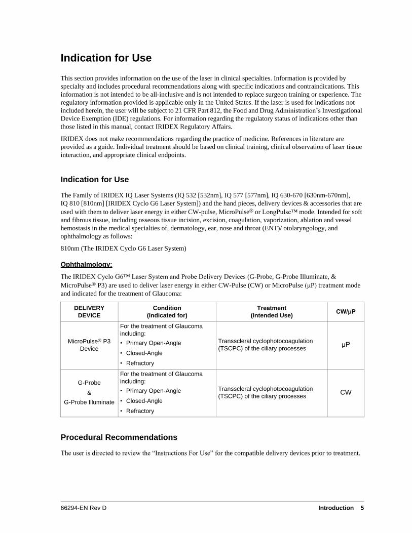
The IRIDEX Cyclo G6™ Laser System and Probe Delivery Devices (G-Probe, G-Probe Illuminate, &
MicroPulse® P3) are used to deliver laser energy in either CW-Pulse (CW) or MicroPulse (μP) treatment mode
and indicated for the treatment of Glaucoma:
DELIVERY
DEVICE
Condition
(Indicated for)
Treatment
(Intended Use)
CW/μP
MicroPulse® P3
Device
For the treatment of Glaucoma
including:
• Primary Open-Angle
• Closed-Angle
• Refractory
Transscleral cyclophotocoagulation
(TSCPC) of the ciliary processes
μP
G-Probe
&
G-Probe Illuminate
For the treatment of Glaucoma
including:
• Primary Open-Angle
• Closed-Angle
• Refractory
Transscleral cyclophotocoagulation
(TSCPC) of the ciliary processes
CW
Procedural Recommendations
The user is directed to review the “Instructions For Use” for the compatible delivery devices prior to treatment.
6 IRIDEX Cyclo G6™ Laser System Operator Manual 66294-EN Rev D
Contraindications
• Any situation where the target tissue cannot be adequately visualized or stabilized.
• Do not treat albino patients who have no pigmentation.
Potential Side Effects or Complications
• As with any surgical procedure, there is the potential risk of infection, inflammation, and post-operative pain.
Specific Warnings and Precautions
It is essential that the surgeon and attending staff be trained in all aspects of the use of this equipment. Surgeons
should obtain detailed instructions for proper use of this laser system before using it to perform any surgical
procedures. For additional Warnings and Cautions, see “Warnings and Cautions” in this chapter. For clinical
information, see “References” at the end of this manual. Proper eye protection must be utilized for the specific
treatment laser wavelength in use (810 nm).
Laser Settings
CAUTION: The following treatment parameters are those reported by physicians using IRIDEX products, or
like products, either in published literature or reported directly to IRIDEX. These treatment
parameters are presented as guidance ultimately it is the physician’s responsibility to determine
safe treatment parameters that will be used on patients on a case by case basis.
The laser energy is recommended to be administered via the probe optical fiber delivery handpiece which is used
intra-ocularly.
Beginning at low power with short duration exposures, the surgeon should note the surgical effect and increase
power, power density, or exposure duration until the desired surgical effect is obtained. The information in the
following tables is intended to provide guidance only for treatment settings, which are not prescriptive for any
condition. The operative needs of each patient should be individually evaluated based on the indication,
treatment location, and on the patient’s medical and wound healing history. If uncertain of expected clinical
response, always start with a conservative setting and increase the setting in small steps.
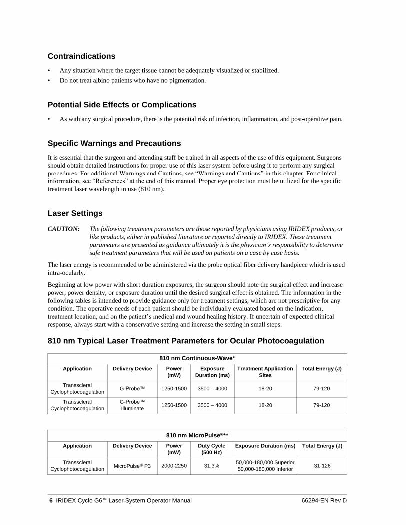
810 nm Typical Laser Treatment Parameters for Ocular Photocoagulation
810 nm Continuous-Wave*
Application Delivery Device Power
(mW)
Exposure
Duration (ms)
Treatment Application
Sites
Total Energy (J)
Transscleral
Cyclophotocoagulation G-Probe™ 1250-1500 3500 – 4000 18-20 79-120
Transscleral
Cyclophotocoagulation
G-Probe™
Illuminate 1250-1500 3500 – 4000 18-20 79-120
810 nm MicroPulse®**
Application Delivery Device Power
(mW)
Duty Cycle
(500 Hz)
Exposure Duration (ms) Total Energy (J)
Transscleral
Cyclophotocoagulation MicroPulse® P3 2000-2250 31.3%
50,000-180,000 Superior
50,000-180,000 Inferior 31-126

66294-EN Rev D Introduction 7
References
*G-PROBE™
1. Gaasterland DE. Diode Laser Cyclophotocoagulation. Glaucoma Today 2009 Mar:35-39.
2. Gaasterland DE, Radcliffe NM, Vold SD, Kammer JA. Reconsidering Transscleral Cyclophotocoagulation.
Supplement to Glaucoma Today 2012 Jan-Feb:1-11
3. Kraus CL, Tychsen L, Lueder GT, Culican SM. Comparison of the Effectiveness and Safety of Transscleral
Cyclophotocoagulation and Endoscopic Cyclophotocoagulation in Pediatric Glaucoma. J Pediatr Ophthalmol
Strabismus 2014;51(2):120-127.
4. Lin SC. Endoscopic and Transscleral Cyclophotocoagulation for the Treatment of Refractory Glaucoma.
J Glaucoma 2008;17:238–247.
5. Olivier MM. Current Options for Cyclophotocoagulation: An overview of transscleral diode photocoagulation
and endocyclophotocoagulation. Glaucoma Today 2012 Mar-Apr:30-34.
6. Schlote T, Derse M, Rassmann K, Nicaeus T, Dietz K, Thiel H. Efficacy and Safety of Contact Transscleral
Diode Laser Cyclophotocoagulation for Advanced Glaucoma. J Glaucoma 2001;10:294-301.
7. Wilensky JT, Kammer J. Long-term Visual Outcome of Transscleral Laser Cyclotherapy in Eyes with
Ambulatory Vision. Ophthalmology 2004;111:1389–1392.
*G-PROBE™ ILLUMINATE: (includes references for G-Probe as well as the two references below)
1. Agrawal P, Martin KR. Ciliary body position variability in glaucoma patients assessed by scleral
transillumination. Eye 2008;22:1499-1503
2. Agrawal P, Dulku S, Nolan W, Sung V. The UK National Cyclodiode Laser Survey. Eye 2010:1-6
**MICROPULSE® P3
1. Radcliffe N, Vold S, Kammer J, Ahmed I, Parekh P, Noecker R, Khatana A. MicroPulse Trans-scleral
Cyclophotocoagulation (mTSCPC) for the Treatment of Glaucoma Using the MicroPulse P3 Device.
AGS, San Diego February 26 -March 1, 2015
2. Aquino MC, Tan AM, Loon SC, Chew PT. Transscleral Micropulse Diode Laser Cyclophotocoagulation as
Effective Adjunctive Treatment prior to Glaucoma Surgery. ARVO 2012 May.
3. Aquino MC, Tan AM, Loon SC, See J, Chew PT. A Randomized Comparative Study of the Safety and Efficacy
of Conventional Versus Micropulse Diode Laser Transscleral Cyclophotocoagulation in Refractory Glaucoma.
ARVO 2011 May.
4. Liu GJ, Mizukawa A, Okisaka S. Mechanism of Intraocular Pressure Decrease after Contact Transscleral
Continuous-Wave Nd:YAG Laser Cyclophotocoagulation. Ophthalmic Res 1994;26:65-79.
5. Schubert HD, Agarwala A. Quantitative CW Nd:YAG Pars Plana Transscleral Photocoagulation in
Postmortem Eyes. Ophthalmic Surgery 1990;21(12):835-39.
6. Aquino MC, Tan AM, Chan YH, Chew PT. Initial Experience with MicroPulse Diode Laser Transscleral
Cyclophotocoagulation for Severe Glaucoma. World Glaucoma Congress 2007 July;P428.
7. Tan AM, Chockalingam M, Aquino MC, Lim ZI, See JL, Chew PT. Micropulse Transscleral Diode Laser
Cyclophotocoagulation in the Treatment of Refractory Glaucoma. Clin Experiment Ophthalmol. 2010
Apr;38(3):266-72
8. Aquino MC, Barton K, Tan AM, Sng C, Li X, Loon SC, Chew PT. Micropulse versus continuous wave trans-
scleral diode cyclophotocoagulation in refractory glaucoma: a randomised exploratory study. Clin Experiment
Ophthalmol May 2014. doi: 10.1111.ceo. 12360 [Epub ahead of print].
9. Kuchar S, Moster M, Waisbourd M. Treatment Outcomes of MicroPulse Trans-scleral Cyclophotocoagulation
in Advanced Glaucoma. Laser Med Sci (2016) 31:393-396.
10. Maslin J, Noecker R, Micropulse Trans-scleral Cyclophotocoagulation for the Treatment of Glaucoma.
Presented at ARVO, May 2-5, 2016.
11. Lin S, Babic K, Masis M, Micropulse transscleral diode laser cyclophotocoagulation: Short term results and
anatomical effects. Presented at AGS 2016, March 3-6, 2016.
12. Maslin J, Chen P, Sinard J, Noecker R, Comparison of acute histopathological changes in human cadaver eyes after
MicroPulse and continuous wave transscleral cyclophotocoagulation. Presented at AGS 2016, March 3-6, 2016.
13. Patel K, Dawood S, Rafay H, Patrianakos T, Giovingo M, Results of a Novel Glaucoma Treatment: MicroPulse
Transscleral Cyclophotocoagulation Diode Laser. Presented at ARVO 2016, May 2-5, 2016.
8 IRIDEX Cyclo G6™ Laser System Operator Manual 66294-EN Rev D
Warnings and Cautions
DANGER:
Do not remove cover as this may expose persons to hazards of electrical shock and laser radiation.
Refer servicing to qualified laser personnel. There is a risk of explosion if a laser system is used in the
presence of flammable anesthetics.
WARNINGS:
Lasers generate a highly concentrated beam of light that may cause injury if improperly used. To
protect the patient and the operating personnel, the entire laser and the appropriate delivery system
operator manuals should be carefully read and comprehended before operation.
Never look directly into the aiming or treatment beam apertures or the fiber-optic cables that deliver
the laser beams, with or without laser safety eyewear.
Never look directly into the laser light source or at laser light scattered from bright reflective surfaces.
Avoid directing the treatment beam at highly reflective surfaces such as metal instruments.
Ensure that all personnel in the treatment room are wearing the appropriate laser safety eyewear.
Never substitute prescription eyewear for laser safety eyewear.
To avoid the risk of electric shock, this equipment must be connected to a supply mains with
protective earth.
Before connecting or disconnecting the power cord, make sure that the area is clear of water and any
spillage and that hands are dry.
Always disconnect the laser by grasping the plug and not the power cord. Power is shut off by
removing the plug from the electrical main.
Instructions provided, indicate not to position the laser to make it difficult to operate the plug of the
power cord since the plug is used to provide isolation from electrical shock. Do not place the laser in
an area where access to the plug of the power cord is obstructed or prevented.
To avoid the risk of electric shock, this equipment must only be connected to a supply main with
protective earth. EN 60601-1:2006/AC:2010
US federal law restricts this device to sale by or on the order of a healthcare practitioner licensed by
the law of the State in which he/she practices to use or order the use of the device.
Use of controls or adjustments or performing of procedures other than those specified herein may
result in hazardous radiation exposure.
Do not operate the equipment in the presence of flammables or explosives, such as volatile anesthetics,
alcohol, and surgical preparation solutions.
Laser plume may contain viable tissue particulates.
Keep the protective cap over the fiber-optic connector when the delivery device is not in use.
66294-EN Rev D Introduction 9
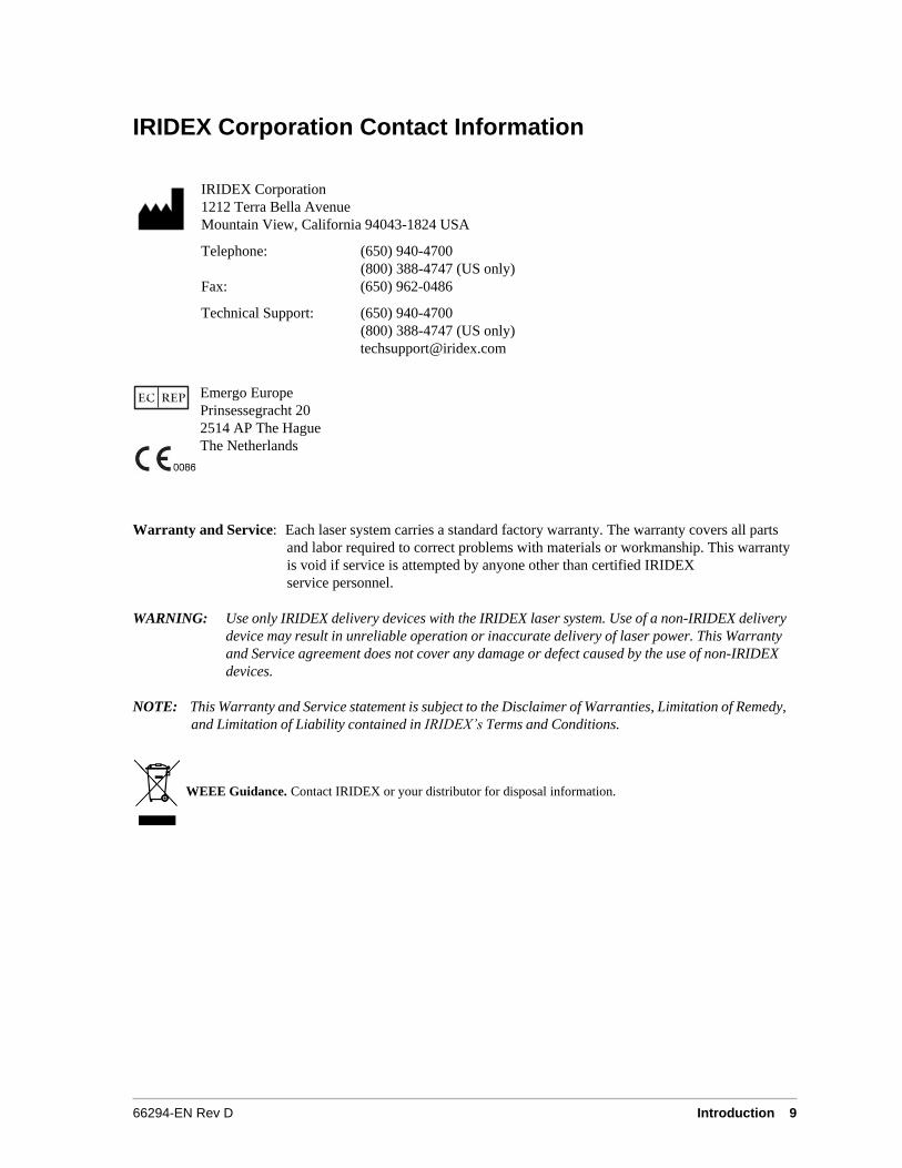
IRIDEX Corporation Contact Information
IRIDEX Corporation
1212 Terra Bella Avenue
Mountain View, California 94043-1824 USA
Telephone: (650) 940-4700
(800) 388-4747 (US only)
Fax: (650) 962-0486
Technical Support: (650) 940-4700
(800) 388-4747 (US only)
Emergo Europe
Prinsessegracht 20
2514 AP The Hague
The Netherlands
Warranty and Service: Each laser system carries a standard factory warranty. The warranty covers all parts
and labor required to correct problems with materials or workmanship. This warranty
is void if service is attempted by anyone other than certified IRIDEX
service personnel.
WARNING: Use only IRIDEX delivery devices with the IRIDEX laser system. Use of a non-IRIDEX delivery
device may result in unreliable operation or inaccurate delivery of laser power. This Warranty
and Service agreement does not cover any damage or defect caused by the use of non-IRIDEX
devices.
NOTE: This Warranty and Service statement is subject to the Disclaimer of Warranties, Limitation of Remedy,
and Limitation of Liability contained in IRIDEX’s Terms and Conditions.
WEEE Guidance. Contact IRIDEX or your distributor for disposal information.
10 IRIDEX Cyclo G6™ Laser System Operator Manual 66294-EN Rev D
2 Setup
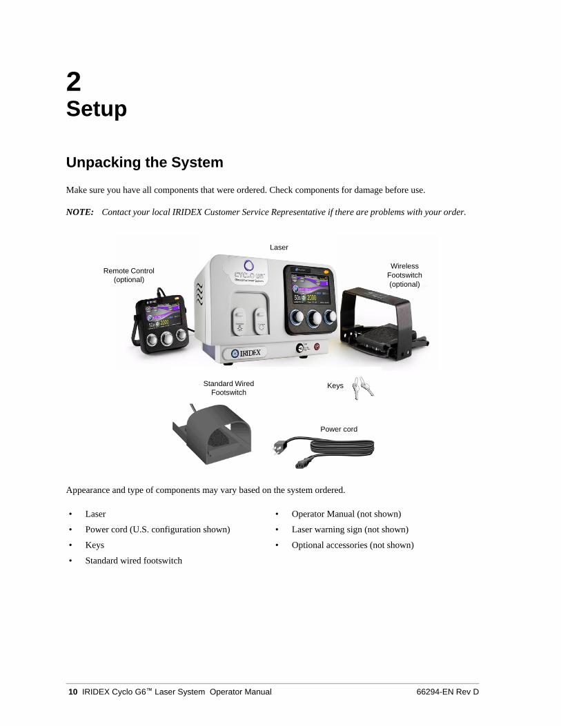
Unpacking the System
Make sure you have all components that were ordered. Check components for damage before use.
NOTE: Contact your local IRIDEX Customer Service Representative if there are problems with your order.
Appearance and type of components may vary based on the system ordered.
• Laser • Operator Manual (not shown)
• Power cord (U.S. configuration shown) • Laser warning sign (not shown)
• Keys • Optional accessories (not shown)
• Standard wired footswitch
Laser
Remote Control
(optional)
Wireless
Footswitch
(optional)
Standard Wired
Footswitch Keys
Power cord
66294-EN Rev D Setup 11
Choosing a Location
Choose a well-ventilated location within the specified operating range of the console.
Place the laser system on a table or on existing operating room equipment. Allow at least 5 cm (2 in.) of
clearance on each side.
In the US, this equipment must be connected to an electrical supply source at 120V or 240V with a center tap.
To ensure that all local electrical requirements can be met, the system is equipped with a medical grade universal
input power supply three-wire grounding plug. When choosing the location, ensure that a grounding-type AC
outlet is available; it is required for safe operation.
The power cord included in the packaging is appropriate for your location. Always use an approved three-wire
grounding cord set. Do not alter the power inlet. To ensure proper grounding, follow local electrical codes before
installing the system.
CAUTIONS:
Do not defeat the purpose of the grounding pin. This equipment is intended to be electrically grounded.
Contact a licensed electrician if your outlet prevents you from inserting the plug.
Do not position or use the system near open flames.
Connecting the Components
CAUTION: Do not connect two footswitches to the laser console.
NOTES: Refer to the appropriate delivery device manual for specific connection instructions.
12 IRIDEX Cyclo G6™ Laser System Operator Manual 66294-EN Rev D
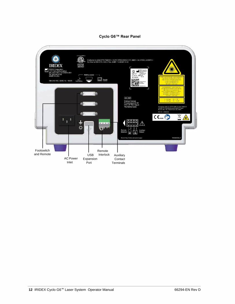
Cyclo G6™ Rear Panel
Footswitch
and Remote Remote
USB Interlock Auxiliary AC Power Expansion Contact
Inlet Port Terminals
66294-EN Rev D Operation 13
3 Operation
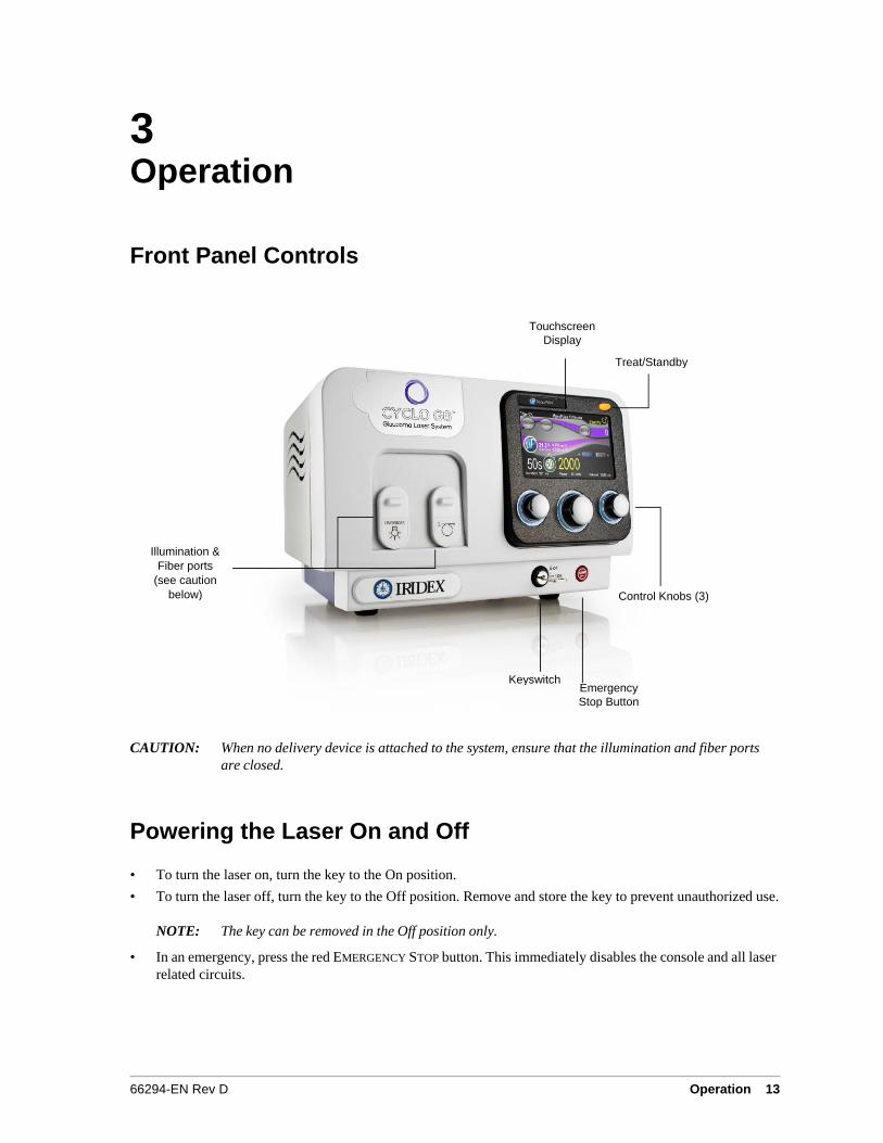
Front Panel Controls
CAUTION: When no delivery device is attached to the system, ensure that the illumination and fiber ports
are closed.
Powering the Laser On and Off
• To turn the laser on, turn the key to the On position.
• To turn the laser off, turn the key to the Off position. Remove and store the key to prevent unauthorized use.
NOTE: The key can be removed in the Off position only.
• In an emergency, press the red EMERGENCY STOP button. This immediately disables the console and all laser
related circuits.
Touchscreen
Display
Treat/Standby Button
Illumination &
Fiber ports
(see caution
below) Control Knobs (3)
Keyswitch Emergency
Stop Button
14 IRIDEX Cyclo G6™ Laser System Operator Manual 66294-EN Rev D
Treating Patients
BEFORE TREATING A PATIENT:
• Ensure that the eye safety filter (as appropriate) is properly installed.
• Ensure that the laser components and delivery device(s) are properly connected.
• Post the laser warning sign outside the treatment room door.
NOTE: Refer to Chapter 6, “Safety and Compliance” and your delivery device manual(s) for important
information about laser safety eyewear and eye safety filters.
TO TREAT A PATIENT:
1. Turn on the laser.
2. Reset the counter.
3. Set the treatment parameters.
4. Position the patient.
5. If required, select an appropriate contact lens for the treatment.
6. Ensure that all ancillary personnel in the treatment room are wearing the appropriate laser safety eyewear.
7. Select Treat mode.
8. Position the aiming beam on the treatment site.
9. Focus or adjust the delivery device as applicable.
10. Press the footswitch to deliver the treatment beam.
TO CONCLUDE PATIENT TREATMENT:
1. Select Standby mode.
2. Record the number of exposures and any other treatment parameters.
3. Turn off the laser and remove the key.
4. Collect the safety eyewear.
5. Remove the warning sign from the treatment room door.
6. Disconnect the delivery device(s).
7. Dispose of the delivery device, it is single-use.
8. If a contact lens was used, handle the lens according to the manufacturer’s instructions.
66294-EN Rev D Operation 15
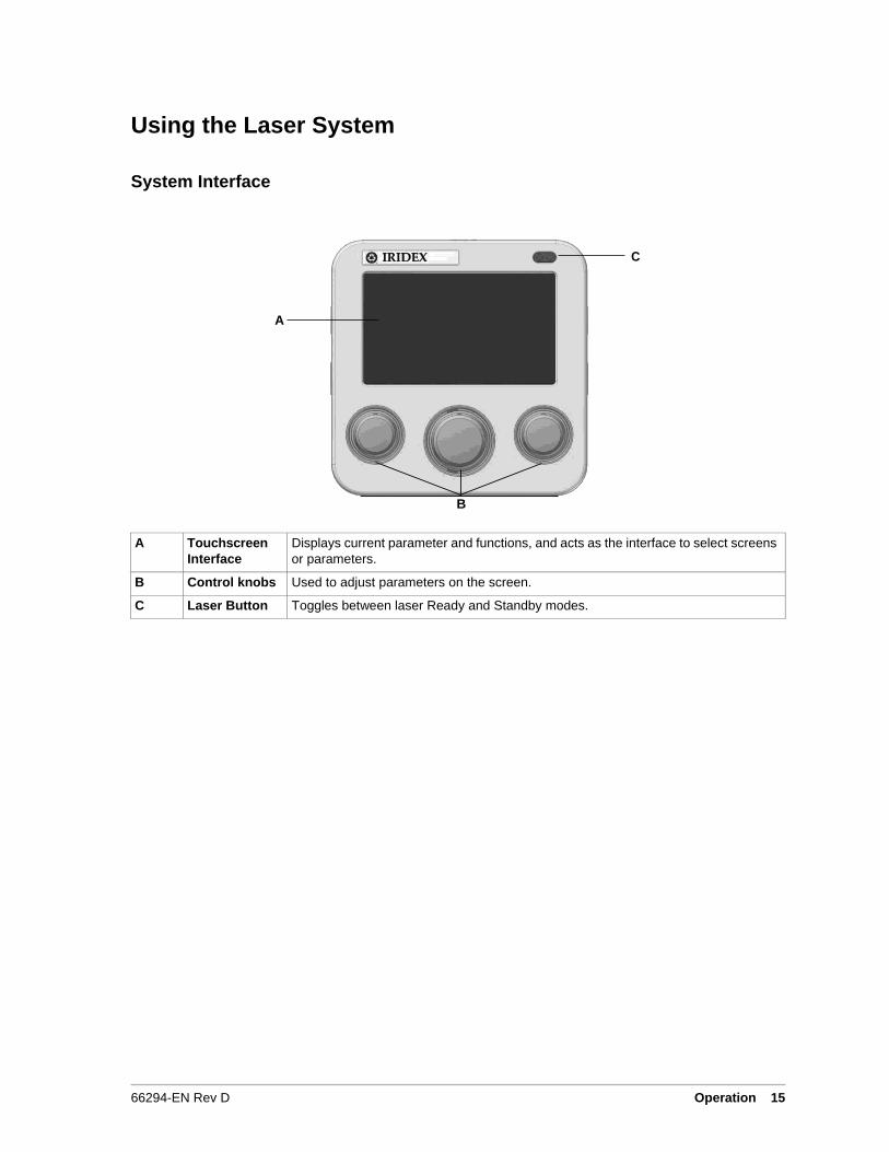
Using the Laser System
System Interface
C
A
A Touchscreen
Interface
Displays current parameter and functions, and acts as the interface to select screens
or parameters.
B Control knobs Used to adjust parameters on the screen.
C Laser Button Toggles between laser Ready and Standby modes.
B
16 IRIDEX Cyclo G6™ Laser System Operator Manual 66294-EN Rev D
A
B
C
G
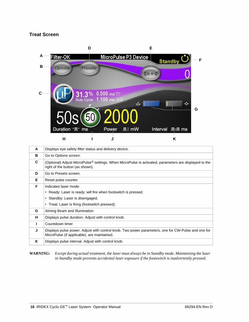
Treat Screen
D E
F
H I J K
A Displays eye safety filter status and delivery device.
B Go to Options screen.
C (Optional) Adjust MicroPulse® settings. When MicroPulse is activated, parameters are displayed to the
right of the button (as shown).
D Go to Presets screen.
E Reset pulse counter.
F Indicates laser mode:
• Ready: Laser is ready; will fire when footswitch is pressed.
• Standby: Laser is disengaged.
• Treat: Laser is firing (footswitch pressed).
G Aiming Beam and Illumination
H Displays pulse duration. Adjust with control knob.
I Countdown timer
J Displays pulse power. Adjust with control knob. Two power parameters, one for CW-Pulse and one for
MicroPulse (if applicable), are maintained.
K Displays pulse interval. Adjust with control knob.
WARNING: Except during actual treatment, the laser must always be in Standby mode. Maintaining the laser
in Standby mode prevents accidental laser exposure if the footswitch is inadvertently pressed.
66294-EN Rev D Operation 17
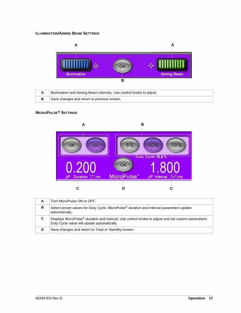
ILLUMINATION/AIMING BEAM SETTINGS
A A
B
A Illumination and Aiming Beam intensity. Use control knobs to adjust.
B Save changes and return to previous screen.
MICROPULSE® SETTINGS
A B
C D C
A Turn MicroPulse ON or OFF.
B Select preset values for Duty Cycle. MicroPulse® duration and Interval parameters update
automatically.
C Displays MicroPulse® duration and interval. Use control knobs to adjust and set custom parameters.
Duty Cycle value will update automatically.
D Save changes and return to Treat or Standby screen.
18 IRIDEX Cyclo G6™ Laser System Operator Manual 66294-EN Rev D
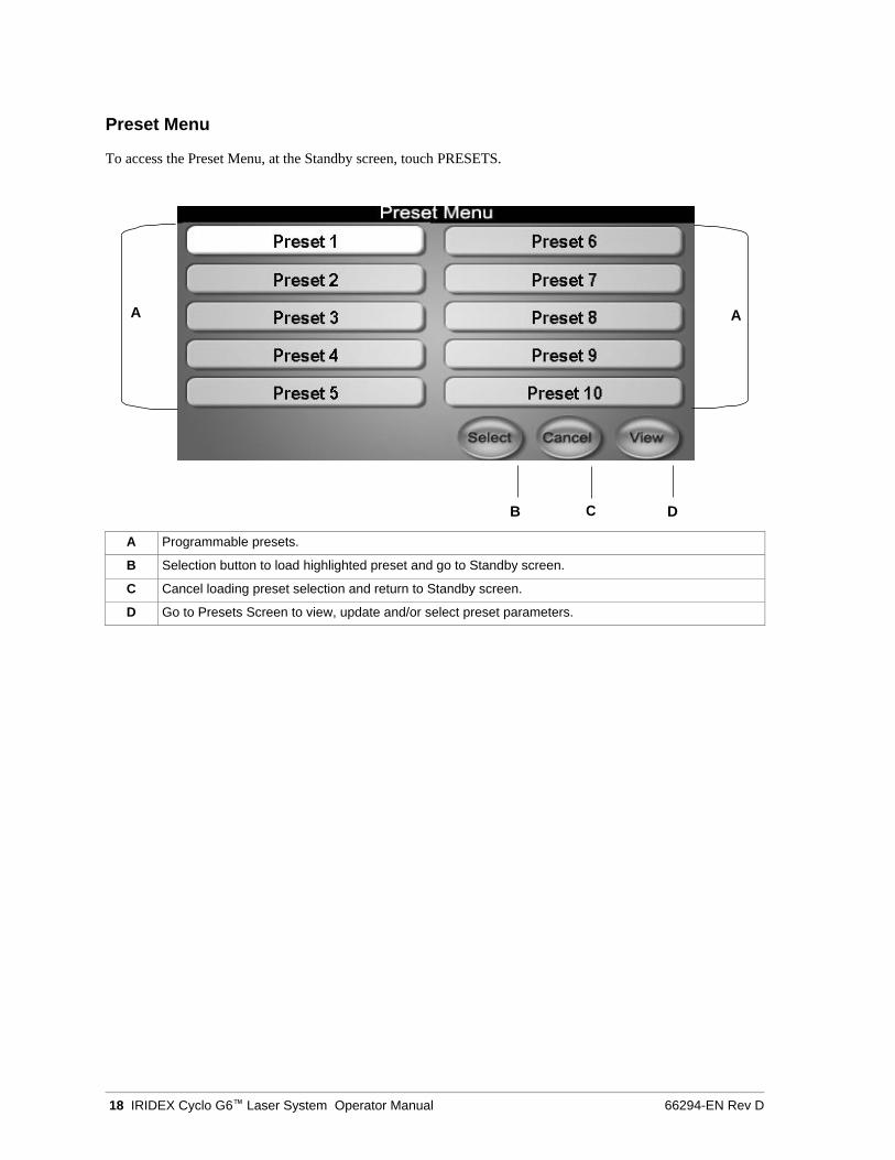
Preset Menu
To access the Preset Menu, at the Standby screen, touch PRESETS.
B C D
A Programmable presets.
B Selection button to load highlighted preset and go to Standby screen.
C Cancel loading preset selection and return to Standby screen.
D Go to Presets Screen to view, update and/or select preset parameters.
A A

66294-EN Rev D Operation 19
Presets Screen
To access the Presets screen, at the Preset Menu, touch VIEW.
A A
B
H C
D E F G
A Go to Previous/Next Preset.
B (Optional) Adjust MicroPulse® settings.
C Use control knobs to select pulse duration, power, and interval.
D Displays Preset name. Press to enter Keyboard mode.
E Save changes and go to Treat screen.
F Discard changes and go to Treat screen with default parameters.
G Import information from Treat screen into selected Preset.
H Aiming Beam and Illumination adjustments.
20 IRIDEX Cyclo G6™ Laser System Operator Manual 66294-EN Rev D
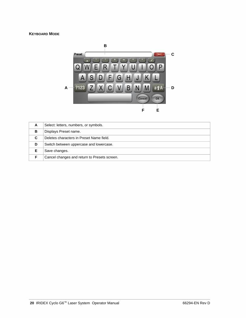
KEYBOARD MODE
B
C
A D
F E
A Select: letters, numbers, or symbols.
B Displays Preset name.
C Deletes characters in Preset Name field.
D Switch between uppercase and lowercase.
E Save changes.
F Cancel changes and return to Presets screen.
66294-EN Rev D Operation 21
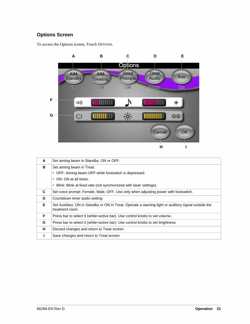
Options Screen
To access the Options screen, Touch OPTIONS.
A B C D E
F
G
H I
A Set aiming beam in Standby: ON or OFF.
B Set aiming beam in Treat:
• OFF: Aiming beam OFF while footswitch is depressed.
• ON: ON at all times.
• Blink: Blink at fixed rate (not synchronized with laser settings).
C Set voice prompt: Female, Male, OFF. Use only when adjusting power with footswitch.
D Countdown timer audio setting
E Set Auxiliary: ON in Standby or ON in Treat. Operate a warning light or auditory signal outside the
treatment room.
F Press bar to select it (white=active bar). Use control knobs to set volume.
G Press bar to select it (white=active bar). Use control knobs to set brightness.
H Discard changes and return to Treat screen.
I Save changes and return to Treat screen.
22 IRIDEX Cyclo G6™ Laser System Operator Manual 66294-EN Rev D
4 Troubleshooting
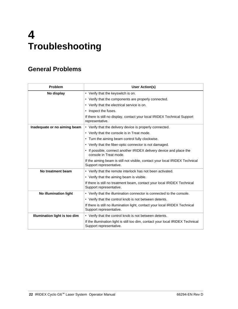
General Problems
Problem User Action(s)
No display • Verify that the keyswitch is on.
• Verify that the components are properly connected.
• Verify that the electrical service is on.
• Inspect the fuses.
If there is still no display, contact your local IRIDEX Technical Support
representative.
Inadequate or no aiming beam • Verify that the delivery device is properly connected.
• Verify that the console is in Treat mode.
• Turn the aiming beam control fully clockwise.
• Verify that the fiber-optic connector is not damaged.
• If possible, connect another IRIDEX delivery device and place the
console in Treat mode.
If the aiming beam is still not visible, contact your local IRIDEX Technical
Support representative.
No treatment beam • Verify that the remote interlock has not been activated.
• Verify that the aiming beam is visible.
If there is still no treatment beam, contact your local IRIDEX Technical
Support representative.
No illumination light • Verify that the illumination connector is connected to the console.
• Verify that the control knob is not between detents.
If there is still no illumination light, contact your local IRIDEX Technical
Support representative.
Illumination light is too dim • Verify that the control knob is not between detents.
If the illumination light is still too dim, contact your local IRIDEX Technical
Support representative.
66294-EN Rev D Troubleshooting 23
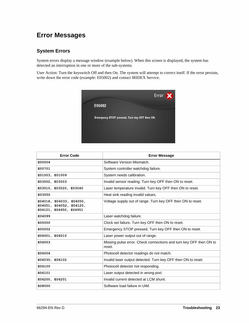
Error Messages
System Errors
System errors display a message window (example below). When this screen is displayed, the system has
detected an interruption in one or more of the sub-systems.
User Action: Turn the keyswitch Off and then On. The system will attempt to correct itself. If the error persists,
write down the error code (example: E05002) and contact IRIDEX Service.
Error Code Error Message
E00004 Software Version Mismatch.
E00701 System controller watchdog failure.
E01003, E01009 System needs calibration.
E03002, E03003 Invalid sensor reading. Turn key OFF then ON to reset.
E03010, E03020, E03040 Laser temperature invalid. Turn key OFF then ON to reset.
E03050 Heat sink reading invalid values.
E04018, E04033, E04050,
E04051, E04052, E04120,
E04121, E04950, E04951
Voltage supply out of range. Turn key OFF then ON to reset.
E04099 Laser watchdog failure.
E05000 Clock set failure. Turn key OFF then ON to reset.
E05002 Emergency STOP pressed. Turn key OFF then ON to reset.
E06001, E06010 Laser power output out of range.
E06003 Missing pulse error. Check connections and turn key OFF then ON to
reset.
E06006 Photocell detector readings do not match.
E06030, E06102 Invalid laser output detected. Turn key OFF then ON to reset.
E06100 Photocell detector not responding.
E06101 Laser output detected in wrong port.
E06200, E06201 Invalid current detected at LCM shunt.
E08000 Software load failure in UIM.
24 IRIDEX Cyclo G6™ Laser System Operator Manual 66294-EN Rev D
User–Correctable Events and Error
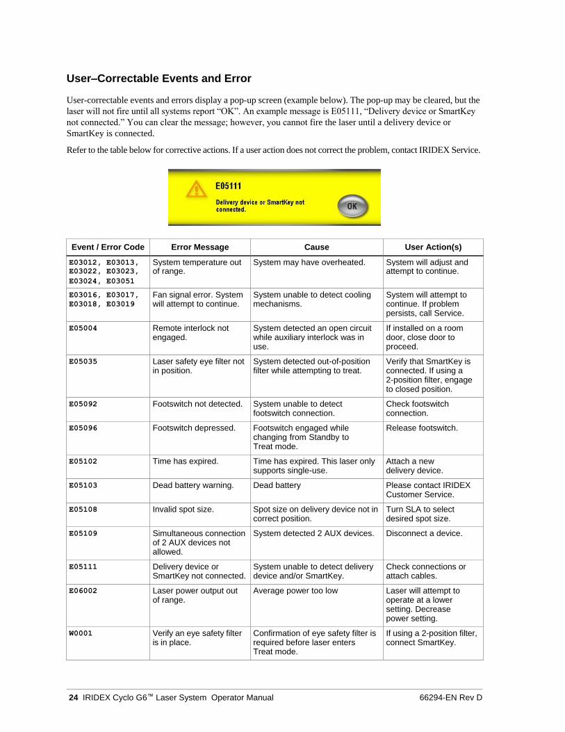
User-correctable events and errors display a pop-up screen (example below). The pop-up may be cleared, but the
laser will not fire until all systems report “OK”. An example message is E05111, “Delivery device or SmartKey
not connected.” You can clear the message; however, you cannot fire the laser until a delivery device or
SmartKey is connected.
Refer to the table below for corrective actions. If a user action does not correct the problem, contact IRIDEX Service.
Event / Error Code Error Message Cause User Action(s)
E03012, E03013, System temperature out System may have overheated. System will adjust and E03022, E03023, of range. attempt to continue. E03024, E03051
E03016, E03017, Fan signal error. System System unable to detect cooling System will attempt to E03018, E03019 will attempt to continue. mechanisms. continue. If problem
persists, call Service.
E05004 Remote interlock not engaged.
System detected an open circuit while auxiliary interlock was in use.
If installed on a room door, close door to proceed.
E05035 Laser safety eye filter not in position.
System detected out-of-position filter while attempting to treat.
Verify that SmartKey is connected. If using a 2-position filter, engage to closed position.
E05092 Footswitch not detected. System unable to detect footswitch connection.
Check footswitch connection.
E05096 Footswitch depressed. Footswitch engaged while changing from Standby to Treat mode.
Release footswitch.
E05102 Time has expired. Time has expired. This laser only supports single-use.
Attach a new delivery device.
E05103 Dead battery warning. Dead battery Please contact IRIDEX Customer Service.
E05108 Invalid spot size. Spot size on delivery device not in correct position.
Turn SLA to select desired spot size.
E05109 Simultaneous connection of 2 AUX devices not allowed.
System detected 2 AUX devices. Disconnect a device.
E05111 Delivery device or SmartKey not connected.
System unable to detect delivery device and/or SmartKey.
Check connections or attach cables.
E06002 Laser power output out of range.
Average power too low Laser will attempt to operate at a lower setting. Decrease power setting.
W0001 Verify an eye safety filter is in place.
Confirmation of eye safety filter is required before laser enters Treat mode.
If using a 2-position filter, connect SmartKey.
66294-EN Rev D Maintenance 25
5 Maintenance
Inspecting and Cleaning the Laser
Clean the outside console covers with soft cloth moistened with a mild detergent. Avoid abrasive or ammonia-
based cleaners.
WARNING: Do not remove covers! Removing covers and shields may result in exposure to dangerous optical
radiation levels and electrical voltages. Only IRIDEX-trained personnel may access the interior
of the laser. The laser has no user serviceable parts.
CAUTION: Turn off the laser before inspecting any delivery device components. Keep the protective cap over
the laser port when the laser is not in use. Always handle fiber-optic cables with extreme care.
Do not coil the cable in a diameter less than 15 cm (6 in.).
Inspecting and Cleaning the Footswitch
TO CLEAN THE FOOTSWITCH:
1. Disconnect the footswitch from the laser (if applicable).
2. Using water, isopropyl alcohol, or a mild detergent, wipe down the surfaces of the footswitch. Avoid
abrasive or ammonia-based cleaners.
3. Allow the footswitch to air-dry completely before reusing.
4. Reconnect the footswitch to the laser.
NOTE: The cable is not sealed and should not be immersed into any cleansing agent.
Verifying the Power Calibration
To ensure that calibration meets the requirements of the National Institute of Standards and Technology (NIST),
the laser treatment power is calibrated at the IRIDEX factory with a power meter and an IRIDEX delivery device
with previously measured transmission.
Periodically, and at least annually, the actual power being delivered through IRIDEX delivery device(s) should
be measured to verify that the laser system is still operating within factory calibration parameters.
Regulatory agencies require that manufacturers of US FDA CDRH Class III and IV and IEC 60825-1 Class 3
and 4 medical lasers supply their customers with power calibration procedures. Only IRIDEX trained factory or
service personnel may adjust the power monitors.
26 IRIDEX Cyclo G6™ Laser System Operator Manual 66294-EN Rev D
TO VERIFY LASER CONSOLE POWER CALIBRATION:
1. Make sure all persons in the room are wearing the appropriate laser safety eyewear.
2. Connect a clean and properly functioning IRIDEX delivery device or test fiber.
NOTE: If a G-Probe, MP3 Device, or other device with a ball-shaped tip is used to perform these tests,
immerse its distal (output) tip in a clear glass container of deionized water to a depth of 5-10 mm
(a laboratory beaker or Petri dish is suitable). Otherwise, incorrect measurements will result.
3. Center the aiming beam on the power meter sensor. Measurement equipment must be capable of measuring
several watts of continuous optical power. Position devices with their tips immersed in water directly above
the upward facing power meter sensor. Direct the aiming beam through the bottom of the container onto the
meter sensor.
CAUTION: A spot size of less than 3 mm diameter can damage the power meter sensor.
4. Set the laser Duration to 3000 ms and the Interval to Single Pulse when a CW delivery device is connected.
Set the Duration to 3000 ms, Interval to Single Pulse, MicroPulse Duration to 1.0 ms and MicroPulse
Interval to 1.0 ms (50% Duty Factor) when a MicroPulse delivery device is connected.
5. Set the laser Power to 200 mW.
6. Place the laser in Treat mode.
7. Direct the aiming beam from the IRIDEX delivery device onto the power sensor, following the power
meter instructions for sampling the laser power.
8. Actuate the footswitch to deliver the treatment beam. Power measured by the meter should stabilize before
the end of the timed exposure. If it does not, increase the Duration appropriately. Record the stabilized
power meter reading in the table below. This value represents the average power delivered by the device.
9. Set the power to 500 mW, actuate the footswitch to deliver the treatment beam, and record the reading.
10. Set the power to 1000 mW, actuate the footswitch to deliver the treatment beam, and record the reading.
11. Set the power to 2000 mW, actuate the footswitch to deliver the treatment beam, and record the reading.
12. When using CW devices, measurements ranging between 80% and 120% of displayed power are
acceptable. When using MicroPulse devices, measurements ranging between 40% and 60% of displayed
power are acceptable (since laser MicroPulse Duty Factor using the above settings is 50%). If the readings
fall outside these acceptable levels, check the power meter, ensure that the beam is accurately positioned on
the power meter detector surface, and check the readings again with another IRIDEX delivery device.
13. If the measurements are still outside acceptable levels, contact your local IRIDEX Technical Support
Representative.
14. Place a signed copy of the tabulated data in your device records for reference during later use and service.
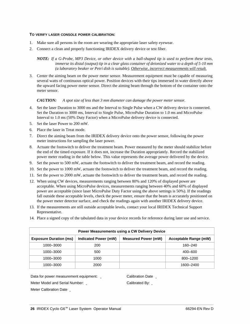
Power Measurements using a CW Delivery Device
Exposure Duration (ms) Indicated Power (mW) Measured Power (mW) Acceptable Range (mW)
1000–3000 200 160–240
1000–3000 500 400–600
1000–3000 1000 800–1200
1000–3000 2000 1600–2400
Data for power measurement equipment:
Meter Model and Serial Number:
Meter Calibration Date
Calibration Date
Calibrated By:
66294-EN Rev D Maintenance 27
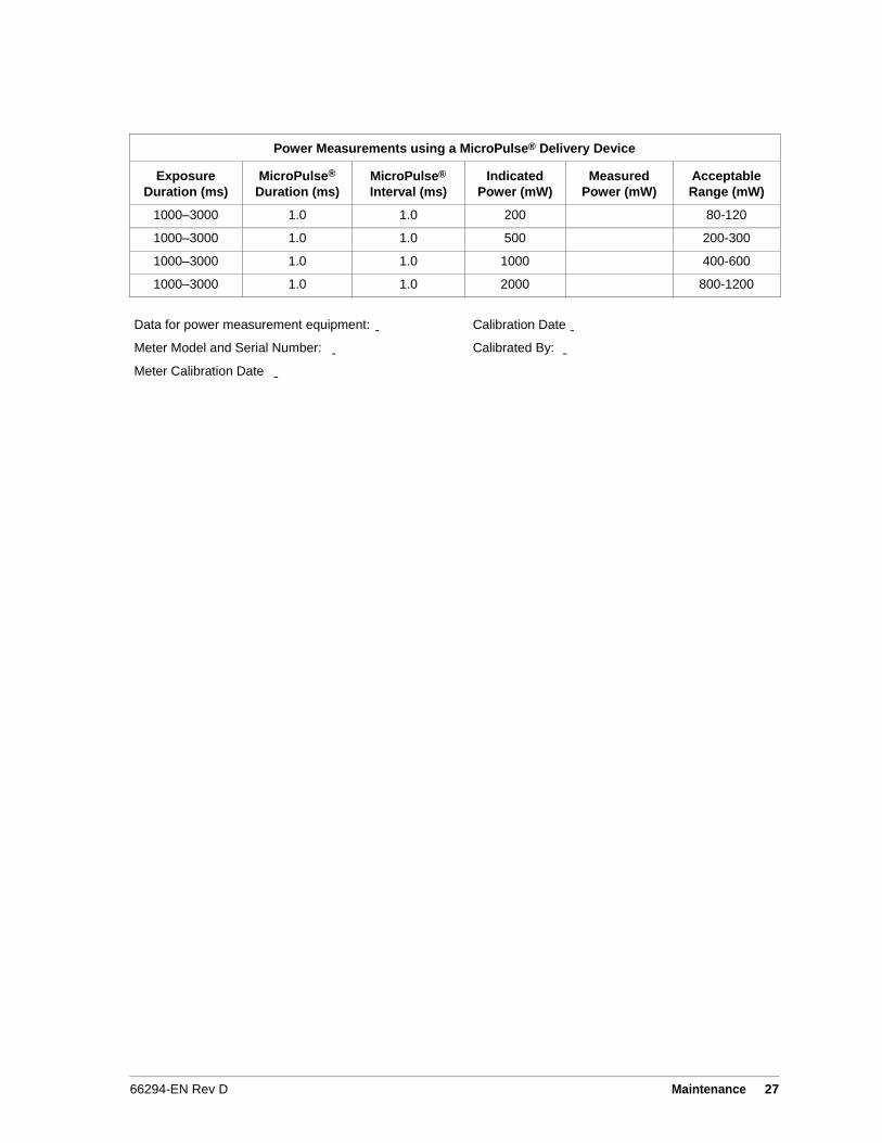
Power Measurements using a MicroPulse® Delivery Device
Exposure
Duration (ms)
MicroPulse®
Duration (ms)
MicroPulse®
Interval (ms)
Indicated
Power (mW)
Measured
Power (mW)
Acceptable
Range (mW)
1000–3000 1.0 1.0 200 80-120
1000–3000 1.0 1.0 500 200-300
1000–3000 1.0 1.0 1000 400-600
1000–3000 1.0 1.0 2000 800-1200
Data for power measurement equipment:
Meter Model and Serial Number:
Meter Calibration Date
Calibration Date
Calibrated By:
28 IRIDEX Cyclo G6™ Laser System Operator Manual 66294-EN Rev D
6 Safety and Compliance
To ensure safe operation and prevent hazards and unintended exposure to the laser beams, read and follow
these instructions:
• To prevent exposure to laser energy, except as a therapeutic application from either direct or diffusely
reflected laser beams, always review and observe the safety precautions outlined in the operator manuals
before using the device.
• This device is intended for use only by a qualified physician. The applicability of the equipment and
treatment techniques selected is your sole responsibility.
• Do not use any device if you think it is not functioning properly.
• Laser beams reflected from specular surfaces can harm your eyes, the patient’s eyes, or others’ eyes. Any
mirror or metal object that reflects the laser beam can constitute a reflection hazard. Be sure to remove all
reflection hazards near the laser. Use non-reflecting instruments whenever possible. Be careful not to direct
the laser beam at unintended objects.
CAUTION: Changes or modifications not expressly approved by the party responsible for compliance could
void the user’s authority to operate the equipment.
Protection for the Physician
Eye safety filters protect the physician from backscattered treatment laser light. Integral eye safety filters are
permanently installed in the Slit Lamp Adapter, LIO, EasyFit Adapter, IRIDEX Integrated Slit Lamp
Workstation, and SL130 Integrated Slit Lamp Workstation. For endophotocoagulation, a separate discrete eye
safety filter assembly must be installed into each viewing path of the operating microscope. All eye safety filters
have an optical density (OD) at the laser wavelength sufficient to permit long-term viewing of diffuse laser light
at Class I levels. When using the dermatology handpieces, always wear the appropriate laser safety eyewear.
Protection for All Treatment Room Personnel
The Laser Safety Officer should determine the need for safety eyewear based on the Maximum Permissible
Exposure (MPE), Nominal Ocular Hazard Area (NOHA), and Nominal Ocular Hazard Distance (NOHD) for
each of the delivery devices used with the laser system, as well as the configuration of the treatment room. For
additional information, refer to ANSI Z136.1, ANSI Z136.3, or IEC 60825-1.
66294-EN Rev D Safety and Compliance 29
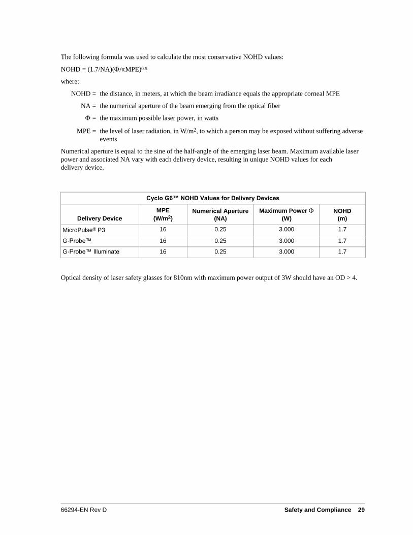
The following formula was used to calculate the most conservative NOHD values:
NOHD = (1.7/NA)(/MPE)0.5
where:
NOHD = the distance, in meters, at which the beam irradiance equals the appropriate corneal MPE
NA = the numerical aperture of the beam emerging from the optical fiber
= the maximum possible laser power, in watts
MPE = the level of laser radiation, in W/m2, to which a person may be exposed without suffering adverse
events
Numerical aperture is equal to the sine of the half-angle of the emerging laser beam. Maximum available laser
power and associated NA vary with each delivery device, resulting in unique NOHD values for each
delivery device.
Cyclo G6™ NOHD Values for Delivery Devices
Delivery Device
MPE
(W/m2)
Numerical Aperture
(NA)
Maximum Power (W)
NOHD
(m)
MicroPulse® P3 16 0.25 3.000 1.7
G-Probe™ 16 0.25 3.000 1.7
G-Probe™ Illuminate 16 0.25 3.000 1.7
Optical density of laser safety glasses for 810nm with maximum power output of 3W should have an OD > 4.
30 IRIDEX Cyclo G6™ Laser System Operator Manual 66294-EN Rev D
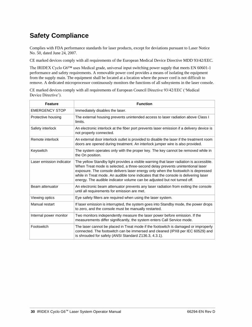
Safety Compliance
Complies with FDA performance standards for laser products, except for deviations pursuant to Laser Notice
No. 50, dated June 24, 2007.
CE marked devices comply with all requirements of the European Medical Device Directive MDD 93/42/EEC.
The IRIDEX Cyclo G6™ uses Medical grade, universal input switching power supply that meets EN 60601-1
performance and safety requirements. A removable power cord provides a means of isolating the equipment
from the supply main. The equipment shall be located at a location where the power cord is not difficult to
remove. A dedicated microprocessor continuously monitors the functions of all subsystems in the laser console.
CE marked devices comply with all requirements of European Council Directive 93/42/EEC (‘Medical
Device Directive’).
Feature Function
EMERGENCY STOP Immediately disables the laser.
Protective housing The external housing prevents unintended access to laser radiation above Class I
limits.
Safety interlock An electronic interlock at the fiber port prevents laser emission if a delivery device is
not properly connected.
Remote interlock An external door interlock outlet is provided to disable the laser if the treatment room
doors are opened during treatment. An interlock jumper wire is also provided.
Keyswitch The system operates only with the proper key. The key cannot be removed while in
the On position.
Laser emission indicator The yellow Standby light provides a visible warning that laser radiation is accessible.
When Treat mode is selected, a three-second delay prevents unintentional laser
exposure. The console delivers laser energy only when the footswitch is depressed
while in Treat mode. An audible tone indicates that the console is delivering laser
energy. The audible indicator volume can be adjusted but not turned off.
Beam attenuator An electronic beam attenuator prevents any laser radiation from exiting the console
until all requirements for emission are met.
Viewing optics Eye safety filters are required when using the laser system.
Manual restart If laser emission is interrupted, the system goes into Standby mode, the power drops
to zero, and the console must be manually restarted.
Internal power monitor Two monitors independently measure the laser power before emission. If the
measurements differ significantly, the system enters Call Service mode.
Footswitch The laser cannot be placed in Treat mode if the footswitch is damaged or improperly
connected. The footswitch can be immersed and cleaned (IPX8 per IEC 60529) and
is shrouded for safety (ANSI Standard Z136.3, 4.3.1).
66294-EN Rev D Safety and Compliance 31
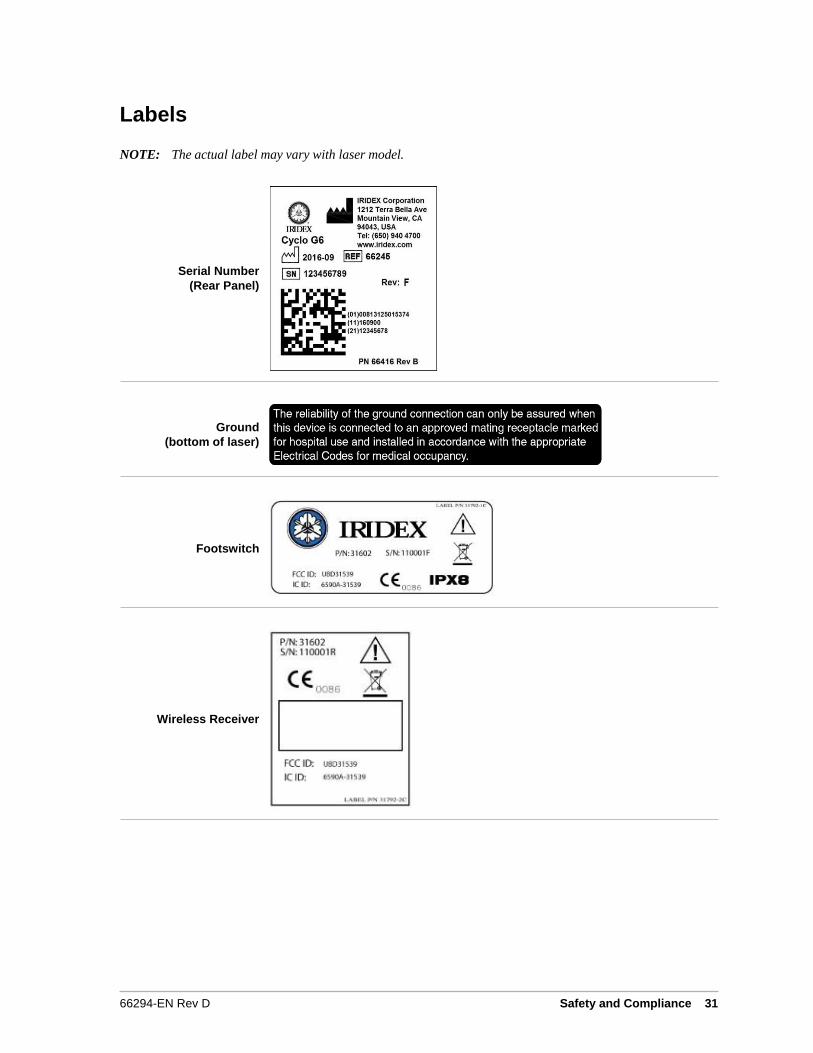
Labels
NOTE: The actual label may vary with laser model.
Serial Number
(Rear Panel)
Ground
(bottom of laser)
Footswitch
Wireless Receiver

32 IRIDEX Cyclo G6™ Laser System Operator Manual 66294-EN Rev D
Remote Control
Laser Warning
Rear Panel of Console
SERIALIZE #s: RCI0100 to RCI9999
66294-EN Rev D Safety and Compliance 33
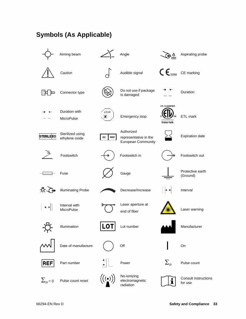
Symbols (As Applicable)
Aiming beam Angle Aspirating probe
Caution Audible signal CE marking
Connector type Do not use if package
is damaged
Duration with
MicroPulse Emergency stop ETL mark
Sterilized using
ethylene oxide
Authorized
representative in the
European Community
Expiration date
Footswitch Footswitch in Footswitch out
Fuse Gauge Protective earth
(Ground)
Illuminating Probe Decrease/Increase Interval
Interval with
MicroPulse
Laser aperture at
end of fiber Laser warning
Illumination Lot number Manufacturer
Date of manufacture Off On
Part number Power n Pulse count
n = 0 Pulse count reset
No-ionizing
electromagnetic
radiation
Consult instructions
for use
Duration

66294-EN Rev D Safety and Compliance 33

34 IRIDEX Cyclo G6™ Laser System Operator Manual 66294-EN Rev D
Power increment
System brightness
Remote control Remote interlock Serial number
Single use Standby Treat
OPERATING
TEMPERATURE
RANGE
10°C to 35°C
SHIPPING
TEMPERATURE
RANGE
-20°C to 60°C
Type B Applied Part -
Applied Parts degree
of protection against
electrical shock -
Type B Symbol
IEC 60417-5840:
IEC 60601-1:2005,
Clause 7.2.10. Label
applied to Probe
Connector
Temperature
limitations:
Label placed on
Console Shipping
Package & Probe Box
Refer to instruction
manual
IPX4
Waste Electrical and
Electronic Equipment
(WEEE)
Enclosure protected
against splashing
water sprayed from
all angles
Initial power
(PowerStep)
IPX8
Pattern is activated
Enclosure protected
against continual
submersion in water
under identified
conditions
Interval between
groups
Number of pulses
(group)
Number of steps
(PowerStep) Power (MicroPulse)
Power increment
(PowerStep) Parameter is locked
Universal serial bus
(USB) Port indicators Laser firing
Laser preparing Speaker Screen
Not made with natural
rubber latex By prescription only
Warning, replace with
fuses as indicated
Item or surface can
be hot and should not
be touched without
taking care
CSA Group Mark
Health Canada
Warning of Optical Radiation
66294-EN Rev D Safety and Compliance 35
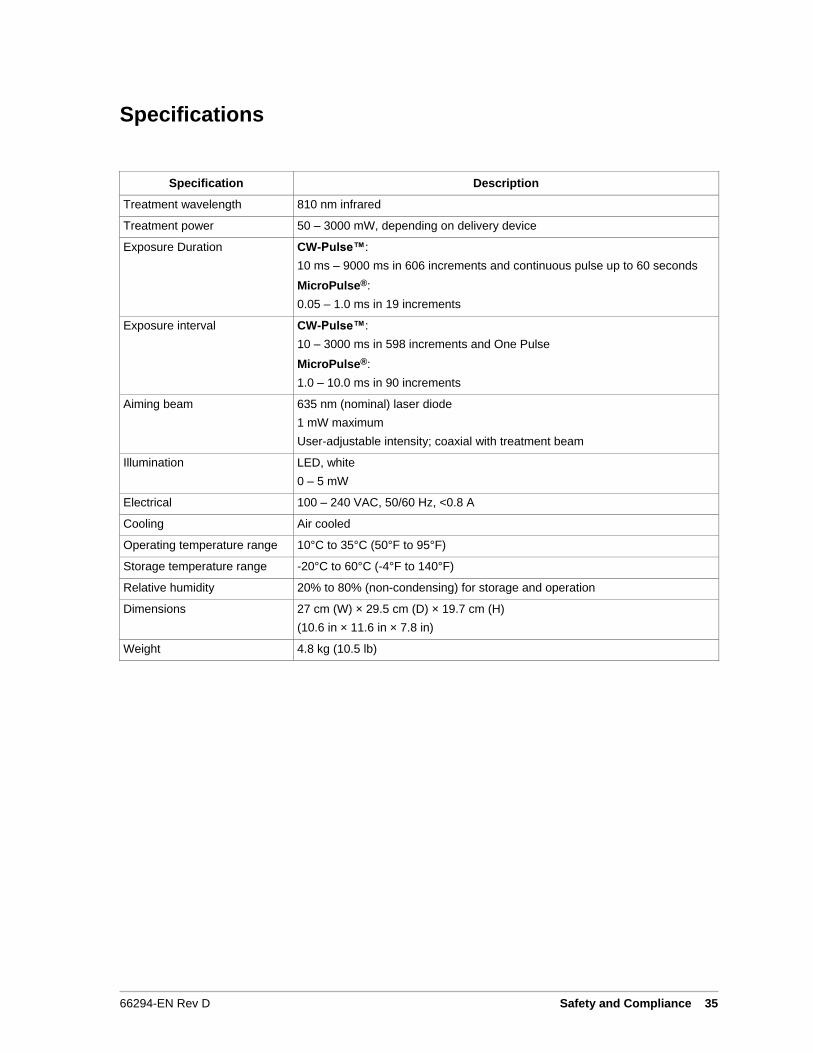
Specifications
Specification Description
Treatment wavelength 810 nm infrared
Treatment power 50 – 3000 mW, depending on delivery device
Exposure Duration CW-Pulse™:
10 ms – 9000 ms in 606 increments and continuous pulse up to 60 seconds
MicroPulse®:
0.05 – 1.0 ms in 19 increments
Exposure interval CW-Pulse™:
10 – 3000 ms in 598 increments and One Pulse
MicroPulse®:
1.0 – 10.0 ms in 90 increments
Aiming beam 635 nm (nominal) laser diode
1 mW maximum
User-adjustable intensity; coaxial with treatment beam
Illumination LED, white
0 – 5 mW
Electrical 100 – 240 VAC, 50/60 Hz, <0.8 A
Cooling Air cooled
Operating temperature range 10°C to 35°C (50°F to 95°F)
Storage temperature range -20°C to 60°C (-4°F to 140°F)
Relative humidity 20% to 80% (non-condensing) for storage and operation
Dimensions 27 cm (W) × 29.5 cm (D) × 19.7 cm (H)
(10.6 in × 11.6 in × 7.8 in)
Weight 4.8 kg (10.5 lb)
36 IRIDEX Cyclo G6™ Laser System Operator Manual 66294-EN Rev D
7 Wireless Footswitch and EMC
Setting Up the Wireless Footswitch
The wireless footswitch comprises:
• Laser console-powered receiver
Connect the wireless receiver to the footswitch receptacle on the rear of the laser. Three pedals (as applicable) on
the footswitch control the following:
• Left pedal = decrease power (hold down to ramp the parameter)
• Center pedal = activate laser
• Right pedal = increase power (hold down to ramp the parameter)
CAUTION: Each footswitch/receiver pair is uniquely linked and will not work with other IRIDEX
footswitches or similar components. Clearly identify each pair to prevent separation of the
linked components.
NOTE: The footswitch is designed to operate within 15 feet (5 meters) of the laser.
Testing the Batteries
NOTE: When batteries need to be replaced, contact your sales representative or IRIDEX Customer Service.
The wireless footswitch was designed with a battery life expectancy of 3 – 5 years of normal operation
and use.
LEDs on the footswitch assist in troubleshooting and indicate battery conditions as follows:
Footswitch LED Display Status
Green flash following pedal depression Footswitch OK
Batteries OK
Amber flash following pedal depression Footswitch OK
Batteries low
Blinking red LED for 10 seconds following pedal depression No RF communication
66294-EN Rev D Wireless Footswitch and EMC 37
EMC Safety Information
The laser system (console and accessories) needs special precautions regarding EMC and needs to be installed
and put into service according to the EMC information provided in this section. Portable and mobile RF
communications equipment can affect this system.
This laser system has been tested and found to comply with the limits for medical devices in IEC 60601-1-2
according to the tables in this section. These limits are designed to provide reasonable protection against harmful
interference in a typical medical installation.
CAUTION: Changes or modifications to this laser system not expressly approved by the party responsible for
compliance could void the user’s authority to operate the equipment and may result in increased
emissions or decreased immunity of the laser system.
The wireless footswitch transmits and receives in the frequency range of 2.41GHz to 2.46GHz with a limited
effective radiated power as described below. The transmissions are continuous transmissions at discrete
frequencies within the transmission frequency range.
The wireless footswitch has been tested and found to comply with the limits for a Class B digital device, pursuant
to Part 15 of the FCC Rules. These limits are designed to provide reasonable protection against harmful
interference in a residential installation. This equipment generates, uses, and can radiate radio frequency energy
and, if not installed and used in accordance with the instructions, may cause harmful interference to radio
communications. However, there is no guarantee that interference will not occur in a particular installation. If the
wireless footswitch does cause harmful interference to radio or television reception, which can be determined by
turning the laser system off and on, the user is encouraged to try to correct the interference by one or more of the
following measures:
• Reorient or relocate the receiving device.
• Increase the separation between the equipment.
• Connect the laser console into an outlet on a circuit different from that to which the receiver is connected.
• Consult IRIDEX Customer Service for help.
This Class B digital apparatus meets all requirements of the Canadian Interference-Causing Equipment
Regulations.
Cet appareil numérique de la classe B respecte toutes les exigences du Réglement sur le matériel brouilleur
du Canada.

38 IRIDEX Cyclo G6™ Laser System Operator Manual 66294-EN Rev D
EMC Requirements for Console and Accessories
Guidance and Manufacturer’s Declaration – Electromagnetic Emissions
This laser system (console and accessories) is intended for use in the electromagnetic environment specified
below. The customer or the user of the laser system should assure that it is used in such an environment.
Emissions Test Compliance
RF emissions
CISPR 11
Group 1 The laser system uses RF energy only for its internal function.
Therefore, its RF emissions are very low and are not likely to
cause any interference in nearby electronic equipment.
RF emissions
CISPR 11
Class A
Harmonic emissions
IEC 61000-3-2
Class A
Voltage fluctuations/
Flicker emissions
Complies
The laser system is suitable for use in all establishments, other than domestic establishments and those directly
connected to the public low-voltage power supply network that supplies buildings used for domestic purposes.
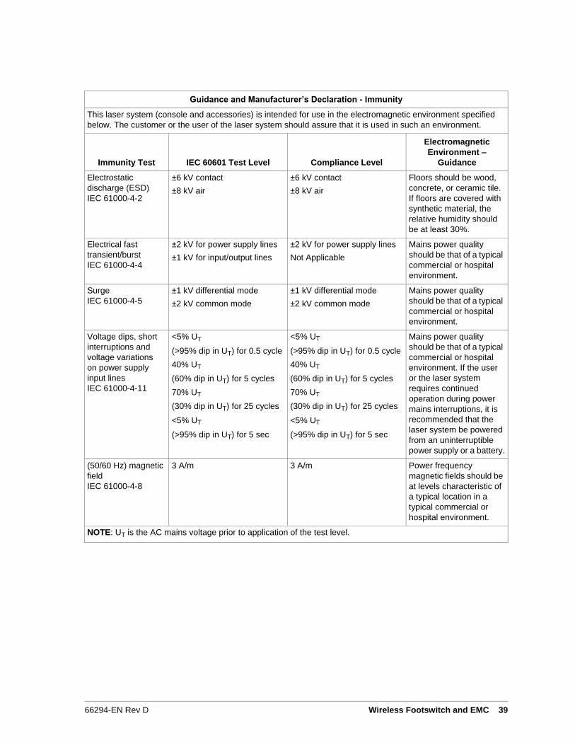
Guidance and Manufacturer’s Declaration - Immunity
This laser system (console and accessories) is intended for use in the electromagnetic environment specified
below. The customer or the user of the laser system should assure that it is used in such an environment.
Immunity Test
IEC 60601 Test Level
Compliance Level
Electromagnetic
Environment –
Guidance
Electrostatic
discharge (ESD)
IEC 61000-4-2
±6 kV contact
±8 kV air
±6 kV contact
±8 kV air
Floors should be wood,
concrete, or ceramic tile.
If floors are covered with
synthetic material, the
relative humidity should
be at least 30%.
Electrical fast
transient/burst
IEC 61000-4-4
±2 kV for power supply lines
±1 kV for input/output lines
±2 kV for power supply lines
Not Applicable
Mains power quality
should be that of a typical
commercial or hospital
environment.
Surge
IEC 61000-4-5
±1 kV differential mode
±2 kV common mode
±1 kV differential mode
±2 kV common mode
Mains power quality
should be that of a typical
commercial or hospital
environment.
Voltage dips, short
interruptions and
voltage variations
on power supply
input lines
IEC 61000-4-11
<5% UT
(>95% dip in UT) for 0.5 cycle
40% UT
(60% dip in UT) for 5 cycles
70% UT
(30% dip in UT) for 25 cycles
<5% UT
(>95% dip in UT) for 5 sec
<5% UT
(>95% dip in UT) for 0.5 cycle
40% UT
(60% dip in UT) for 5 cycles
70% UT
(30% dip in UT) for 25 cycles
<5% UT
(>95% dip in UT) for 5 sec
Mains power quality
should be that of a typical
commercial or hospital
environment. If the user
or the laser system
requires continued
operation during power
mains interruptions, it is
recommended that the
laser system be powered
from an uninterruptible
power supply or a battery.
(50/60 Hz) magnetic
field
IEC 61000-4-8
3 A/m 3 A/m Power frequency
magnetic fields should be
at levels characteristic of
a typical location in a
typical commercial or
hospital environment.
NOTE: UT is the AC mains voltage prior to application of the test level.
66294-EN Rev D Wireless Footswitch and EMC 39
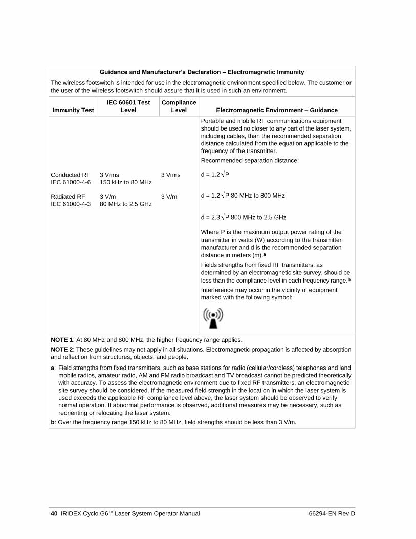
Guidance and Manufacturer’s Declaration – Electromagnetic Immunity
The wireless footswitch is intended for use in the electromagnetic environment specified below. The customer or
the user of the wireless footswitch should assure that it is used in such an environment.
Immunity Test
IEC 60601 Test
Level
Compliance
Level
Electromagnetic Environment – Guidance
Conducted RF 3 Vrms 3 Vrms
IEC 61000-4-6 150 kHz to 80 MHz
Radiated RF 3 V/m 3 V/m
IEC 61000-4-3 80 MHz to 2.5 GHz
Portable and mobile RF communications equipment
should be used no closer to any part of the laser system,
including cables, than the recommended separation
distance calculated from the equation applicable to the
frequency of the transmitter.
Recommended separation distance:
d = 1.2 P
d = 1.2 P 80 MHz to 800 MHz
d = 2.3 P 800 MHz to 2.5 GHz
Where P is the maximum output power rating of the
transmitter in watts (W) according to the transmitter
manufacturer and d is the recommended separation
distance in meters (m).a
Fields strengths from fixed RF transmitters, as
determined by an electromagnetic site survey, should be
less than the compliance level in each frequency range.b
Interference may occur in the vicinity of equipment
marked with the following symbol:
NOTE 1: At 80 MHz and 800 MHz, the higher frequency range applies.
NOTE 2: These guidelines may not apply in all situations. Electromagnetic propagation is affected by absorption
and reflection from structures, objects, and people.
a: Field strengths from fixed transmitters, such as base stations for radio (cellular/cordless) telephones and land
mobile radios, amateur radio, AM and FM radio broadcast and TV broadcast cannot be predicted theoretically
with accuracy. To assess the electromagnetic environment due to fixed RF transmitters, an electromagnetic
site survey should be considered. If the measured field strength in the location in which the laser system is
used exceeds the applicable RF compliance level above, the laser system should be observed to verify
normal operation. If abnormal performance is observed, additional measures may be necessary, such as
reorienting or relocating the laser system.
b: Over the frequency range 150 kHz to 80 MHz, field strengths should be less than 3 V/m.
40 IRIDEX Cyclo G6™ Laser System Operator Manual 66294-EN Rev D
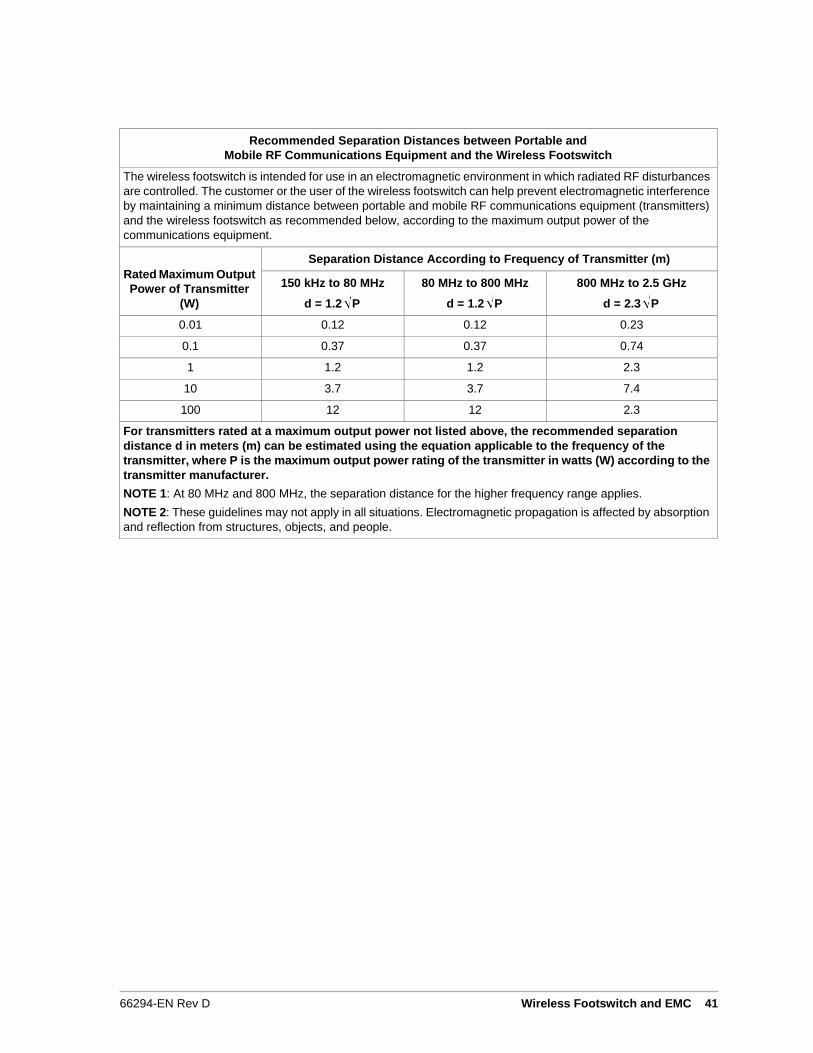
Recommended Separation Distances between Portable and
Mobile RF Communications Equipment and the Wireless Footswitch
The wireless footswitch is intended for use in an electromagnetic environment in which radiated RF disturbances
are controlled. The customer or the user of the wireless footswitch can help prevent electromagnetic interference
by maintaining a minimum distance between portable and mobile RF communications equipment (transmitters)
and the wireless footswitch as recommended below, according to the maximum output power of the
communications equipment.
Rated Maximum Output
Power of Transmitter
(W)
Separation Distance According to Frequency of Transmitter (m)
150 kHz to 80 MHz
d = 1.2 P
80 MHz to 800 MHz
d = 1.2 P
800 MHz to 2.5 GHz
d = 2.3 P
0.01 0.12 0.12 0.23
0.1 0.37 0.37 0.74
1 1.2 1.2 2.3
10 3.7 3.7 7.4
100 12 12 2.3
For transmitters rated at a maximum output power not listed above, the recommended separation
distance d in meters (m) can be estimated using the equation applicable to the frequency of the
transmitter, where P is the maximum output power rating of the transmitter in watts (W) according to the
transmitter manufacturer.
NOTE 1: At 80 MHz and 800 MHz, the separation distance for the higher frequency range applies.
NOTE 2: These guidelines may not apply in all situations. Electromagnetic propagation is affected by absorption
and reflection from structures, objects, and people.
66294-EN Rev D Wireless Footswitch and EMC 41