Embed Size (px)
Citation preview

15
IP Routing—Configuring RIP, OSPF, BGP, and PBR
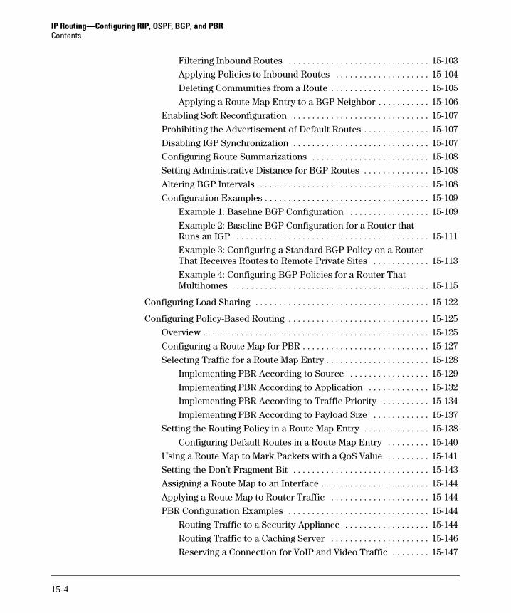
Contents
Overview . . . . . . . . . . . . . . . . . . . . . . . . . . . . . . . . . . . . . . . . . . . . . . . . . . . . . 15-6
Routing Protocols . . . . . . . . . . . . . . . . . . . . . . . . . . . . . . . . . . . . . . . . . . 15-6
Dynamic Routing Protocols Supported on the ProCurve Secure Router . . . . . . . . . . . . . . . . . . . . . . . . . . . . . . . . . . . . . . . . . . 15-7
How Routing Protocols Work . . . . . . . . . . . . . . . . . . . . . . . . . . . . . 15-7
Advantages and Disadvantages of Routing Protocols . . . . . . . . 15-10
Load Sharing . . . . . . . . . . . . . . . . . . . . . . . . . . . . . . . . . . . . . . . . . . . . . 15-11
Configuring RIP . . . . . . . . . . . . . . . . . . . . . . . . . . . . . . . . . . . . . . . . . . . . . . 15-12
RIP Process . . . . . . . . . . . . . . . . . . . . . . . . . . . . . . . . . . . . . . . . . . . 15-12
RIP Updates, v1 and v2 . . . . . . . . . . . . . . . . . . . . . . . . . . . . . . . . . 15-13
Speeding Convergence: Split Horizon, Poison Reverse, and Triggered Updates . . . . . . . . . . . . . . . . . . . . . . . . . . . . . . . . . 15-15
RIP Timing Intervals . . . . . . . . . . . . . . . . . . . . . . . . . . . . . . . . . . . 15-17
RIP Configuration Considerations . . . . . . . . . . . . . . . . . . . . . . . . 15-18
Selecting a RIP Version . . . . . . . . . . . . . . . . . . . . . . . . . . . . . . . . . . . . 15-19
Setting a Global RIP Version . . . . . . . . . . . . . . . . . . . . . . . . . . . . 15-20
Setting RIP Versions for Particular Interfaces . . . . . . . . . . . . . . 15-20
Specifying Networks That Will Participate in RIP . . . . . . . . . . . . . . 15-21
Redistributing Routes . . . . . . . . . . . . . . . . . . . . . . . . . . . . . . . . . . . . . . 15-22
Redistributing Connected Routes . . . . . . . . . . . . . . . . . . . . . . . . 15-23
Redistributing OSPF Routes . . . . . . . . . . . . . . . . . . . . . . . . . . . . . 15-24
RIP Route Filtering . . . . . . . . . . . . . . . . . . . . . . . . . . . . . . . . . . . . . . . . 15-24
Creating an ACL to Act as a RIP Filter . . . . . . . . . . . . . . . . . . . . 15-25
Applying a RIP Filter . . . . . . . . . . . . . . . . . . . . . . . . . . . . . . . . . . . 15-25
Example RIP Filter . . . . . . . . . . . . . . . . . . . . . . . . . . . . . . . . . . . . 15-27
15-1

IP Routing—Configuring RIP, OSPF, BGP, and PBRContents
Enabling and Disabling Route Summarization for Classful Subnets . . . . . . . . . . . . . . . . . . . . . . . . . . . . . . . . . . . . . . . . . . 15-27
Configuring a Passive Interface: Prohibiting an Interface from Sending Updates . . . . . . . . . . . . . . . . . . . . . . . . . . . . . . . . . . . . . 15-30
Altering RIP Intervals . . . . . . . . . . . . . . . . . . . . . . . . . . . . . . . . . . . . . . 15-31
Configuring OSPF . . . . . . . . . . . . . . . . . . . . . . . . . . . . . . . . . . . . . . . . . . . . . 15-32
LSAs . . . . . . . . . . . . . . . . . . . . . . . . . . . . . . . . . . . . . . . . . . . . . . . . . 15-33
Point-to-Point Versus Multi-Access Networks . . . . . . . . . . . . . . 15-34
Areas . . . . . . . . . . . . . . . . . . . . . . . . . . . . . . . . . . . . . . . . . . . . . . . . 15-34
LSA Types . . . . . . . . . . . . . . . . . . . . . . . . . . . . . . . . . . . . . . . . . . . . 15-37
Route Computation . . . . . . . . . . . . . . . . . . . . . . . . . . . . . . . . . . . . 15-38
OSPF Configuration Concerns . . . . . . . . . . . . . . . . . . . . . . . . . . . 15-39
Setting the Router ID . . . . . . . . . . . . . . . . . . . . . . . . . . . . . . . . . . . . . . 15-44
Advertising Networks and Establishing OSPF Areas . . . . . . . . . . . . 15-45
Defining an OSPF Network Within an Area . . . . . . . . . . . . . . . . 15-45
Configuring Stub Areas . . . . . . . . . . . . . . . . . . . . . . . . . . . . . . . . . 15-46
Route Summarization (ABRs): Advertising a Link to One Area to Routers in Another Area . . . . . . . . . . . . . . . . . . . . . 15-47
Example Configuration of OSPF Areas . . . . . . . . . . . . . . . . . . . . 15-52
Prohibiting the Advertisement of Networks . . . . . . . . . . . . . . . . . . . 15-54
Generating a Default External Route (ASBR) . . . . . . . . . . . . . . . . . . 15-54
Configuring Route Summaries for ASBRs . . . . . . . . . . . . . . . . . . . . . 15-55
Configuring Cost Calculation for a Link . . . . . . . . . . . . . . . . . . . . . . . 15-56
Redistributing Routes Discovered by Other Protocols (ASBRs) . . . . . . . . . . . . . . . . . . . . . . . . . . . . . . . . . . . . . . . . 15-58
Redistributing RIP Routes . . . . . . . . . . . . . . . . . . . . . . . . . . . . . . 15-58
Redistributing Connected and Static Routes . . . . . . . . . . . . . . . 15-59
Configuring the Default Metric for Redistributed Routes . . . . 15-60
Changing a Router’s DR Priority . . . . . . . . . . . . . . . . . . . . . . . . . . . . . 15-60
Altering OSPF Intervals . . . . . . . . . . . . . . . . . . . . . . . . . . . . . . . . . . . . 15-60
Configuring OSPF Authentication . . . . . . . . . . . . . . . . . . . . . . . . . . . . 15-62
Example OSPF Configuration . . . . . . . . . . . . . . . . . . . . . . . . . . . . . . . 15-64
15-2

IP Routing—Configuring RIP, OSPF, BGP, and PBRContents
Configuring BGP . . . . . . . . . . . . . . . . . . . . . . . . . . . . . . . . . . . . . . . . . . . . . . 15-67
BGP Advantages . . . . . . . . . . . . . . . . . . . . . . . . . . . . . . . . . . . . . . . 15-68
VRF and MPLS . . . . . . . . . . . . . . . . . . . . . . . . . . . . . . . . . . . . . . . . 15-69
Multihoming . . . . . . . . . . . . . . . . . . . . . . . . . . . . . . . . . . . . . . . . . . 15-70
BGP Neighbors . . . . . . . . . . . . . . . . . . . . . . . . . . . . . . . . . . . . . . . . 15-70
BGP Messages . . . . . . . . . . . . . . . . . . . . . . . . . . . . . . . . . . . . . . . . 15-71
BGP Configuration Concerns . . . . . . . . . . . . . . . . . . . . . . . . . . . . 15-71
Enabling BGP . . . . . . . . . . . . . . . . . . . . . . . . . . . . . . . . . . . . . . . . . . . . . 15-73
Advertising Local Networks . . . . . . . . . . . . . . . . . . . . . . . . . . . . . . . . . 15-73
Setting the Router ID . . . . . . . . . . . . . . . . . . . . . . . . . . . . . . . . . . . . . . 15-74
Configuring a BGP Neighbor . . . . . . . . . . . . . . . . . . . . . . . . . . . . . . . . 15-75
Setting the BGP Neighbor ID . . . . . . . . . . . . . . . . . . . . . . . . . . . . 15-75
Specifying the Local and Remote AS . . . . . . . . . . . . . . . . . . . . . . 15-75
Load Balancing . . . . . . . . . . . . . . . . . . . . . . . . . . . . . . . . . . . . . . . . . . . 15-76
Balancing Loads over Multiple Connections to the Same Neighbor: Specifying the Source for Updates . . . . . . . . . . . . . . 15-77
Balancing Loads over Connections to Different Neighbors . . . 15-78
Creating Prefix Lists: Configuring Filters for Route Exchange . . . . 15-81
Naming the List . . . . . . . . . . . . . . . . . . . . . . . . . . . . . . . . . . . . . . . 15-82
Assigning the Entry an Order . . . . . . . . . . . . . . . . . . . . . . . . . . . . 15-82
Discarding or Allowing Routes . . . . . . . . . . . . . . . . . . . . . . . . . . . 15-82
Specifying the Network Address . . . . . . . . . . . . . . . . . . . . . . . . . 15-82
Specifying the Range of Prefix Lengths . . . . . . . . . . . . . . . . . . . 15-83
Applying Filters . . . . . . . . . . . . . . . . . . . . . . . . . . . . . . . . . . . . . . . 15-83
Example BGP Policies . . . . . . . . . . . . . . . . . . . . . . . . . . . . . . . . . . 15-84
Example Prefix List Configuration . . . . . . . . . . . . . . . . . . . . . . . 15-88
Configuring Route Maps: Creating More Complex Policies for Route Exchange . . . . . . . . . . . . . . . . . . . . . . . . . . . . . . . . . . . . . . . 15-88
Creating a Route Map Entry . . . . . . . . . . . . . . . . . . . . . . . . . . . . . 15-90
Configuring a Community List . . . . . . . . . . . . . . . . . . . . . . . . . . . 15-90
Configuring an AS Path List . . . . . . . . . . . . . . . . . . . . . . . . . . . . . 15-91
Defining the Routes that a Router Can Advertise . . . . . . . . . . . 15-92
Placing a Route in a Community: Requesting a Neighbor to Advertise a Route to Certain Peers Only . . . . . . . . . . . . . . . . 15-97
Prepending Private AS Numbers for Load Balancing . . . . . . . . 15-99
Setting a Multi-Exit Discriminator Metric for Load Balancing . . . . . . . . . . . . . . . . . . . . . . . . . . . . . . . . . . . . . . . 15-100
15-3
IP Routing—Configuring RIP, OSPF, BGP, and PBRContents
Filtering Inbound Routes . . . . . . . . . . . . . . . . . . . . . . . . . . . . . . 15-103
Applying Policies to Inbound Routes . . . . . . . . . . . . . . . . . . . . 15-104
Deleting Communities from a Route . . . . . . . . . . . . . . . . . . . . . 15-105
Applying a Route Map Entry to a BGP Neighbor . . . . . . . . . . . 15-106
Enabling Soft Reconfiguration . . . . . . . . . . . . . . . . . . . . . . . . . . . . . 15-107
Prohibiting the Advertisement of Default Routes . . . . . . . . . . . . . . 15-107
Disabling IGP Synchronization . . . . . . . . . . . . . . . . . . . . . . . . . . . . . 15-107
Configuring Route Summarizations . . . . . . . . . . . . . . . . . . . . . . . . . 15-108
Setting Administrative Distance for BGP Routes . . . . . . . . . . . . . . 15-108
Altering BGP Intervals . . . . . . . . . . . . . . . . . . . . . . . . . . . . . . . . . . . . 15-108
Configuration Examples . . . . . . . . . . . . . . . . . . . . . . . . . . . . . . . . . . . 15-109
Example 1: Baseline BGP Configuration . . . . . . . . . . . . . . . . . 15-109
Example 2: Baseline BGP Configuration for a Router that Runs an IGP . . . . . . . . . . . . . . . . . . . . . . . . . . . . . . . . . . . . . . . . . 15-111
Example 3: Configuring a Standard BGP Policy on a Router That Receives Routes to Remote Private Sites . . . . . . . . . . . . 15-113
Example 4: Configuring BGP Policies for a Router That Multihomes . . . . . . . . . . . . . . . . . . . . . . . . . . . . . . . . . . . . . . . . . . 15-115
Configuring Load Sharing . . . . . . . . . . . . . . . . . . . . . . . . . . . . . . . . . . . . . 15-122
Configuring Policy-Based Routing . . . . . . . . . . . . . . . . . . . . . . . . . . . . . . 15-125
Overview . . . . . . . . . . . . . . . . . . . . . . . . . . . . . . . . . . . . . . . . . . . . . . . . 15-125
Configuring a Route Map for PBR . . . . . . . . . . . . . . . . . . . . . . . . . . . 15-127
Selecting Traffic for a Route Map Entry . . . . . . . . . . . . . . . . . . . . . . 15-128
Implementing PBR According to Source . . . . . . . . . . . . . . . . . 15-129
Implementing PBR According to Application . . . . . . . . . . . . . 15-132
Implementing PBR According to Traffic Priority . . . . . . . . . . 15-134
Implementing PBR According to Payload Size . . . . . . . . . . . . 15-137
Setting the Routing Policy in a Route Map Entry . . . . . . . . . . . . . . 15-138
Configuring Default Routes in a Route Map Entry . . . . . . . . . 15-140
Using a Route Map to Mark Packets with a QoS Value . . . . . . . . . 15-141
Setting the Don’t Fragment Bit . . . . . . . . . . . . . . . . . . . . . . . . . . . . . 15-143
Assigning a Route Map to an Interface . . . . . . . . . . . . . . . . . . . . . . . 15-144
Applying a Route Map to Router Traffic . . . . . . . . . . . . . . . . . . . . . 15-144
PBR Configuration Examples . . . . . . . . . . . . . . . . . . . . . . . . . . . . . . 15-144
Routing Traffic to a Security Appliance . . . . . . . . . . . . . . . . . . 15-144
Routing Traffic to a Caching Server . . . . . . . . . . . . . . . . . . . . . 15-146
Reserving a Connection for VoIP and Video Traffic . . . . . . . . 15-147
15-4

IP Routing—Configuring RIP, OSPF, BGP, and PBRContents
Troubleshooting Routing . . . . . . . . . . . . . . . . . . . . . . . . . . . . . . . . . . . . . . 15-148
Monitoring the Routing Table . . . . . . . . . . . . . . . . . . . . . . . . . . . . . . 15-148
Monitoring Routes . . . . . . . . . . . . . . . . . . . . . . . . . . . . . . . . . . . . . . . . 15-151
Clearing Routes . . . . . . . . . . . . . . . . . . . . . . . . . . . . . . . . . . . . . . . . . . 15-151
Troubleshooting RIP . . . . . . . . . . . . . . . . . . . . . . . . . . . . . . . . . . . . . . 15-153
Router Not Receiving Routes . . . . . . . . . . . . . . . . . . . . . . . . . . . 15-153
Other Routers Not Receiving Routes to the Local Router’s Subnets . . . . . . . . . . . . . . . . . . . . . . . . . . . . . . . . . . . . . 15-154
Troubleshooting OSPF . . . . . . . . . . . . . . . . . . . . . . . . . . . . . . . . . . . . 15-155
Troubleshooting an Internal Router . . . . . . . . . . . . . . . . . . . . . 15-158
Troubleshooting an ABR . . . . . . . . . . . . . . . . . . . . . . . . . . . . . . . 15-162
Troubleshooting BGP . . . . . . . . . . . . . . . . . . . . . . . . . . . . . . . . . . . . . 15-164
Strategies and Tools . . . . . . . . . . . . . . . . . . . . . . . . . . . . . . . . . . 15-164
Troubleshooting a Prefix List . . . . . . . . . . . . . . . . . . . . . . . . . . . 15-172
Troubleshooting a Route Map . . . . . . . . . . . . . . . . . . . . . . . . . . 15-173
Other Common BGP Problems . . . . . . . . . . . . . . . . . . . . . . . . . 15-174
Monitoring and Troubleshooting PBR . . . . . . . . . . . . . . . . . . . . . . . 15-175
Quick Start . . . . . . . . . . . . . . . . . . . . . . . . . . . . . . . . . . . . . . . . . . . . . . . . . . 15-178
RIP Routing . . . . . . . . . . . . . . . . . . . . . . . . . . . . . . . . . . . . . . . . . . . . . 15-179
OSPF Routing . . . . . . . . . . . . . . . . . . . . . . . . . . . . . . . . . . . . . . . . . . . 15-179
Configuring an Internal Router . . . . . . . . . . . . . . . . . . . . . . . . . 15-180
Configuring an ABR . . . . . . . . . . . . . . . . . . . . . . . . . . . . . . . . . . . 15-181
Configuring an ASBR . . . . . . . . . . . . . . . . . . . . . . . . . . . . . . . . . . 15-182
Configuring BGP . . . . . . . . . . . . . . . . . . . . . . . . . . . . . . . . . . . . . . . . . 15-183
Configuring PBR . . . . . . . . . . . . . . . . . . . . . . . . . . . . . . . . . . . . . . . . . 15-184
15-5

IP Routing—Configuring RIP, OSPF, BGP, and PBROverview
Overview
This chapter describes how to configure routing protocols and policy based routing (PBR). Before attempting to configure a routing protocol, you should understand:
■ IP addressing, including how a subnet mask divides an IP address into a network address and a host address
■ classful and classless IP networks
■ classless interdomain routing (CIDR) notation
■ variable length subnets
■ routing tables
■ the way a router uses a route to determine how to forward a packet
You can review these concepts in Chapter 11: Configuring Static Routes of the Basic Management and Configuration Guide.
Routing Protocols
A routing table contains a route to every destination network that a router knows how to reach. When you configure interfaces on the ProCurve Secure Router, they are listed as directly connected interfaces in the routing table. You can manually add routes to this table to specify destination networks. (For more information, see Chapter 11: Configuring Static Routes of the Basic Management and Configuration Guide.)
However, as a network becomes larger and more complicated, manually configuring every route on every router becomes infeasible. Even when you use default routes and hub routers to minimize the number of routes individual routers must know, manually configuring routes for an expanding a network can be time-consuming.
Entering static routes is also prone to errors: you can easily press the wrong key and enter routes incorrectly.
Instead of configuring static routes, you can use dynamic routing protocols, which enable routers to exchange routing information with other routers in the network. Each router can then use this information to build its routing table.
15-6

IP Routing—Configuring RIP, OSPF, BGP, and PBROverview
Dynamic Routing Protocols Supported on the ProCurve Secure Router
The ProCurve Secure Router supports three routing protocols—each of which it can use alone or in conjunction with the others:
■ Routing Information Protocol (RIP) versions 1 and 2
■ Open Shortest Path First (OSPF) version 2
■ Border Gateway Protocol (BGP) version 4
RIP and OSPF are Interior Gateway Protocols (IGPs); they are designed to operate in a single autonomous system (AS). (An AS is a group of networks administered by the same authority.) Although they are IGPs, RIP v2 can be used to learn external routes, and OSPF allows a router to redistribute or advertise external routes to other routers in the OSPF network.
BGP is an Exterior Gateway Protocol (EGP), which allows routers in different autonomous systems to exchange routes. Because BGP routers must regulate traffic between networks controlled by organizations with different policies—and at times competing aims—BGP is designed to allow administrators to customize a policy for route exchange. On the ProCurve Secure Router, BGP provides IP services for private networks.
How Routing Protocols Work
A router constructs its routing table using the information it receives from other routers. The router changes its routing table in response to routing updates that provide additional information or notification that conditions in the network have changed (for example, a link has failed). This responsive-ness explains why using a routing protocol is often called dynamic routing.
A routing protocol governs how routers exchange routes and other network information with each other. The protocol must dictate parameters such as the following:
■ How routers compute a route’s metric and select the best route for their routing table—Routing protocols can have a relatively complicated sys-tem for calculating a route’s metric. Usually, you do not need to under-stand exactly how this calculation is performed. However, you should understand the criteria that the routing protocol uses to calculate a route, so that you can select the best routing protocol (or protocols) for your network environment. If necessary, you can change which routes are chosen by altering the default metrics that a protocol assigns certain routes.
15-7

IP Routing—Configuring RIP, OSPF, BGP, and PBROverview
■ What information routers include in routing updates—With some routing protocols, routers exchange their entire routing tables. With other routing protocols, routers exchange only portions of the routing table. Routers that are running a link-state protocol, such as OSPF, do not exchange actual routes. Instead, these routers exchange information about their links. Each router then uses this information to generate a network topology and calculates its own best routes according to this topology. In addition, some routing protocols allow routers to generate route summarizations or summary routes, which advertise an entire range of networks in a single entry in the routing update.
■ Which routers and router interfaces send and receive updates—Most protocols specify that when routers receive an update on an interface, they do not send the same update from that interface. This common sense rule minimizes overhead. Some routing protocols also cut down on pack-ets circulating through the network by assigning different routers differ-ent roles. For example, only the designated router (DR) in an OSPF subnet floods link-state advertisements (LSAs) to other routers in the subnet, and only area border routers (ABRs) store information about the entire AS. If you understand the role of each router in your WAN, you can configure routers to minimize congestion.
■ When routers send and receive updates and hellos—To lower overhead and conserve bandwidth, you can alter how often routers send certain messages.
You can fine tune the routing protocol to best fit your router’s role in your network topology. Some protocols provide more flexibility in implementation than others. In general, OSPF and BGP provide more options for customizing advertisements for your particular network environment. However, the con-figuration for these protocols can be more complex than the configuration for RIP.
Before you implement a routing protocol on your network, you should evalu-ate the options each protocol provides and then determine which one will work best for your network environment. Table 15-1 compares how RIP, OSPF, and BGP control basic options. You can learn about each protocol in more detail in the overview for the configuration section on that protocol.
15-8

IP Routing—Configuring RIP, OSPF, BGP, and PBROverview
Table 15-1. Routing Protocol Comparison
Option RIP OSPF BGP
Metric computation and route selection
Number of hops to the destination.
• Inverse bandwidth• Type of service (ToS) (rarely
used)
Variety of policies:• external or internal route• number of hops• autonomous systems through
which the route passes• weight• prefix length
Information in updates
Routers send the complete RIP routing table.
Different types of LSAs include different information:• a link and its status:
– link to a network– link to another router
• router ID of every router in a multi-access network
• summary route to a range of networks in an area (sent by ABRs)
• route to autonomous system border router, or ASBR (sent by ABRs)
• external routes or default route for external traffic (sent by ASBRs)
Updates include:• New route.• Withdrawn routes.• Routes include autonomous
systems through which packets must pass.
• Internal filters screen which routes the router advertises to a neighbor.
The routers that send and receive updates
• All router interfaces on RIP networks.
• The interface that receives a route advertises it as unreachable (split horizon with poison reverse).
• Passive interfaces receive updates but do not send them.
• In point-to-point networks, neighboring routers exchange LSAs.
• In multi-access networks, all routers send LSAs to a DR and backup DR (BDR) and receive LSAs from a DR.
• ABRs send route summaries into stub areas.
BGP routers communicate only with manually configured neighbors.
The intervals when routers send and receive updates
• Routers send updates every 30 seconds.
• Routers send updates immediately after a change in network topology (triggered updates).
• Neighbors and DRs send LSAs:– not more than every 5
seconds– not less than every 30
minutes– when topology changes
• Routers send: – an ACK when they receive an
LSA– a hello every 10 seconds
• Routers only send messages to update routes.
• Routers can send keepalive messages.
15-9

IP Routing—Configuring RIP, OSPF, BGP, and PBROverview
Advantages and Disadvantages of Routing Protocols
Dynamic routing can provide reliable routes. OSPF, for example, can select routes according to fairly sophisticated criteria, such as link state and band-width, and BGP can take an organization’s policies into account. The best route at one moment may not always be the best route, and dynamic routing protocols can track these changes. Dynamic routing also adapts well to changes in network topology, including node failures as well as network expansion.
On the other hand, routing protocols consume bandwidth as routers exchange updates and CPU processes as routers calculate the best routes. In addition, a router that has been carelessly configured may send updates to unauthorized devices, creating a security vulnerability. However, a well-designed network eliminates many of these problems.
N o t e You should not use a dynamic routing protocol, particularly RIP, over a dial-up connection because the period updates may keep the connection open longer than necessary—costing your organization money.
Table 15-2 lists some advantages and disadvantages of each protocol. As you can see, different protocols provide different best uses. You can use protocols in conjunction with each other. For example, a router can run OSPF on the private network and BGP to connect to the Internet.
Table 15-2. Advantages and Disadvantages of Routing Protocols
Protocol Advantages Disadvantages Uses
RIP • Configuration is simple.• RIP v2 can communicate with
an external network.
• Convergence is relatively slow.
• Metric is based only on hop count.
• If used to connect to an ISP, the ISP must redistribute the routes into BGP.
• LANs • Simple WANs• Connecting to an external
network• Not used over dial-up
connections
OSPF • Accurate routes take link speed and cost into account.
• Convergence is fast.• Overhead is as low as RIP if
the network is well-designed.
• Configuration is complicated.• Overhead can be high.• OSPF cannot be used as an
EGP without redistribution.
• More extensive LANs and WANs
• Not used over dial-up connections
15-10

IP Routing—Configuring RIP, OSPF, BGP, and PBROverview
The administrative distance for a protocol indicates how reliable the router considers routes discovered by that protocol to be. The lower the administra-tive distance, the more trusted the route. Table 15-3 shows the default admin-istrative distance for the various types of routes that the ProCurve Secure Router can learn.
Table 15-3. Hierarchy of Routes (Most Trusted to Least Trusted)
Load Sharing
Typically, a routing table can only include one best route for each destination. Even if the router learns multiple, equally good routes to the same destination, it must select one. Other routes cannot be used unless the selected route fails for some reason. However, the ProCurve Secure Router can also implement load sharing, which enables it to add multiple routes to the same destination to its routing table. This option enables the router to use redundant connec-tions to the same remote site.
When you enable load sharing, the router can place up to six routes to the same destination in its active routing table. It can learn these routes from any source—that is, you can enter them manually or the router can learn them using a dynamic routing protocol. However, keep in mind that load sharing allows the router to select multiple best routes. The routes must all have the same metric and administrative distance; otherwise, only the route with the
BGP • ISPs use BGP.• BGP provides tight control
over which routes are advertised and accepted.
• Overhead is relatively low.
• Configuration is complicated.• The network must also run an
IGP.
• Connecting to an ISP• Not used over dial-up
connections
Protocol Advantages Disadvantages Uses
Type of Route Default Administrative Distance
directly connected 0
static 1
BGP • 20 for external routes• 200 for internal and local routes
OSPF 110
RIP v1 and v2 120
15-11

IP Routing—Configuring RIP, OSPF, BGP, and PBRConfiguring RIP
lowest values will be selected. Because different routing protocols have different administrative distances, the multiple routes will generally be dis-covered using the same dynamic protocol.
The router can share traffic over the routes based on destination, assigning traffic destined to some hosts to one route and traffic destined to other hosts to another route. In this case, the traffic may not be exactly balanced over the multiple connections, but the more sessions the router supports, the more evenly balanced the traffic will be.
The router can also share the traffic in a round-robin manner, alternating between the routes every time it routes a new packet to the destination network. Configuring the router to load share in this way, however, can cause packets to arrive at the destination out of order and is not generally recom-mended.
Configuring RIP
RIP is a well-known and commonly used distance-vector routing protocol. Although originally developed for LANs, RIP can also be used in WANs. RIP is simple to configure but can be slow to converge. However, the ProCurve Secure Router implements split horizon with poison reverse and triggered updates to solve many potential convergence problems.
Because route selection relies purely on hop count, RIP may not always generate the best routes for WANs, which usually include links of varying bandwidth. In such an environment, the lowest hop count is not always the fastest or best route.
RIP Process
On the ProCurve Secure Router, RIP interfaces transmit:
■ all RIP routes
■ routes to all networks directly connected on RIP interfaces
■ all routes redistributed into RIP, which can include OSPF and static routes as well as routes to networks connected through non-RIP interfaces
Each route includes a metric that specifies how many hops the advertising interface is from the destination.
15-12

IP Routing—Configuring RIP, OSPF, BGP, and PBRConfiguring RIP
When a router receives a route that it does not know from a neighbor, it adds it to its routing table. The source of the update becomes the next-hop address for the destination, and the metric is the advertised metric plus one. That is, because the router is one hop from the source of the update, the router is also one more hop from the destination. After the router adds the route to its table, it can advertise this route itself, with the incremented metric.
The ProCurve Secure Router sends out all RIP routes on all RIP interfaces. Before sending a RIP route, however, the ProCurve Secure Router examines the next-hop address, or the source of the route. If the router is sending an update to a source for a particular route, it sends a poison reverse instead of the normal route. A poison reverse is a route with a metric of 16 (which is infinity for RIP). The poison reverse distinguishes a legitimate redundant route from a route that the local router has received from the neighbor. Essentially, the poison reverse informs the neighbor that it cannot reach the network in question through the local router. This mechanism is called split horizon with poison reverse, and the rationale for it is explained in “Speeding Convergence: Split Horizon, Poison Reverse, and Triggered Updates” on page 15-15.
Routers change entries in their routing tables for several reasons:
■ The neighbor listed as the next-hop address changes the metric for the route. The router then changes the metric for the route in its own table to the new metric plus one.
■ A different neighbor advertises a route with a lower metric. The router changes the route to list this neighbor as the next-hop address and enters the new metric.
■ The router does not receive information about the route for the entire length of the invalid interval. The router marks the route for deletion. It sends out poison updates for the route for two update cycles before removing the route entirely from its routing table.
RIP Updates, v1 and v2
RIP update packets contain different information, depending on whether the RIP version is 1 or 2.
A RIP v1 packet includes:
■ a command field—indicating whether the packet is a request or a reply
■ a version field (set at 1)
15-13

IP Routing—Configuring RIP, OSPF, BGP, and PBRConfiguring RIP
■ an address family field—set at 2, indicating that addresses are in IPv4 format
■ up to 25 entries, each consisting of:
• a destination IP address
• a metric, which is the number of hops to the destination address from the router that is sending the packet
When a router discovers a new or better route from a RIP v1 update, it assumes that the neighbor from which it received the update is the next hop for the route. The router adds one to the metric for its own routing table entry.
RIP v2 fixes several shortcomings of RIP v1. RIP v2 provides route summari-zation for classful networks and supports EGPs. A RIP v2 packet includes:
■ a command field—indicating whether the packet is a request or a reply
■ a version field
■ a routing domain—identifying the routing daemon that produced the message, which allows a device to run several RIP processes at once
■ an address family field
■ a route tag (which includes the AS number for use with EGPs)
■ up to 25 entries, each consisting of:
• a destination IP address
• a subnet mask—providing support for variable-length subnets
• a next-hop IP address
• a metric—the number of hops to the destination address from the next-hop address
When a router discovers a new or better route to a destination from a RIP v2 packet, it enters the route with the next-hop IP address specified in the packet. If the next-hop IP address field is all zeros, the router assumes that the source of the packet is the next-hop IP address. (This assumption provides some backward compatibility with RIP v1).
RIP v1 interfaces broadcast their routing updates to the entire subnet. RIP v2 routers join the group for the RIP v2 multicast address (224.0.0.9) and multi-cast updates to this address. Therefore, RIP v1 and v2 interfaces may not receive each other’s updates. You must take care to configure the router to send and listen for the correct version of RIP.
15-14

IP Routing—Configuring RIP, OSPF, BGP, and PBRConfiguring RIP
Speeding Convergence: Split Horizon, Poison Reverse, and Triggered Updates
One shortcoming of RIP is its relatively slow convergence in some network environments. Routers send updates every 30 seconds. In a large network, a router may not receive accurate and up-to-date information on a route for several minutes.
Another problem with slow convergence is that it can trigger a network-clogging count to infinity when a connection fails. For example, examine the network in Figure 15-1 and consider the updates that each router receives for Network 1 when routers run simple RIP without split horizon or poison reverse.
Figure 15-1. Network That Does Not Use Split Horizon or Poison Reverse
Router B is directly connected to Network 1, so it advertises a route to it with a metric of 1. Routers A and C receive this route from Router B. They both store the route to Network 1 with B as the next-hop address and a metric of 2.
Routers A and C then begin advertising this route. Router C receives the route from Router A. It does not alter its routing table to indicate that Router A is the next hop, because the metric (2) is higher than that advertised by Router B. Router B also receives the route from Router A. Nothing in the update Router B receives from Router A indicates that this route is ultimately through Router B itself. Router B simply rejects the route for the same reason Router C did: the metric is higher than the route it already has.
Router A Router B
Network 1
If no connection fails
Destination Next Hop Metric
* 1 B 21 A 31 D 5
Router C Router D
4 hops
15-15

IP Routing—Configuring RIP, OSPF, BGP, and PBRConfiguring RIP
As long as the network remains stable, this process continues smoothly. However, problems arise if the topology changes.
Consider what happens when the link between Router B and Network 1 fails. (See Figure 15-2.) Router B begins advertising a route to Network 1 with a metric of 16 to indicate that it is unreachable. Routers A and C receive this update from Router B and change the metric, but not before they have already sent their own routes for Network 1 with a metric of 2. Router A receives the route from Router C, and Router C receives the same route from Router A.
Because these routes have a lower metric than the route through Router B, Routers A and C store these routes in their routing tables (adding one to the metric). (See Figure 15-2.) Router B may receive the route from either Router A or C. As mentioned earlier, Router B has no way to determine that this route ultimately points back to itself and so is invalid. Because its own connection to Network 1 has failed, Router B accepts the route.
Figure 15-2. Count to Infinity
Routers A and C now each have a route to Network 1 with a metric of 3, pointing to each other. In the next update cycle, Router A receives the route from Router C. It updates the route in its table with a metric of 4. Router C, receiving the update from Router A, does the same. The next time the routers advertise the route, it has a metric of 4. Eventually, the metric will reach 16, and the routers will determine that they cannot reach Network 1 through each other. This process is called a count to infinity, and it can significantly slow convergence.
Router A Router B
Network 1
Before connection fails
Destination Next Hop Metric
* 1 B 21 A 31 D 5
Router C Router D
4 hops
After connection fails
Destination Next Hop Metric
1 B 16* 1 A 3
1 D 5
15-16
IP Routing—Configuring RIP, OSPF, BGP, and PBRConfiguring RIP
Worse, the count to infinity interferes with convergence to an actual valid route. For example, Router C in Figure 15-2 also connects to Network 1 through a five-hop redundant route. Router C waits until the count to infinity for the invalid route reaches 6 before it starts using and advertising the correct route.
Split horizon is one solution for convergence problems. Split horizon specifies that an interface should not send updates about a route to the interface from which it received the route. In other words, routers assume that the router from which they originally received a route to a destination is more directly connected to and up-to-date on that destination. Split horizon also minimizes the number of packets sent during routine operations.
In the network shown in Figure 15-2, split horizon would cut short the count to infinity. Consider the period during which Routers A and C believe that they can reach Network 1 through each other. As dictated by split horizon, Router A does not send an update for Network 1 to Router C because Router C is its source for the route. However, Router C takes Router A as its source, and when Router A does not send the route to Network 1, Router C eventually times out the route.
The ProCurve Secure Router supports split horizon with poison reverse. This variation of split horizon specifies that a router advertises a route to the neighbor from which it received it, but with a metric of 16. When routers point to each other as sources for a route, they immediately inform each other that the route is unreachable instead of waiting for the route to time out.
The ProCurve Secure Router also supports triggered updates, which lets a router immediately send an update when the status of one of its interfaces changes, instead of waiting 30 seconds. Triggered updates speed convergence and also decrease the chance that another router will have time to send an update that includes an invalid route.
RIP Timing Intervals
RIP specifies certain intervals at which routers must send updates or remove routes for which they have not received current information. Routers use RIP timers to regulate these intervals.
Routers broadcast their routing table at the close of every update interval, which determines the timing for normal, maintenance updates. In addition to sending these normal updates, the ProCurve Secure Router also sends trig-gered updates: it broadcasts an update immediately whenever it changes the metric for a route. In practice, triggered updates are most important for speeding convergence when a network connection goes down.
15-17

IP Routing—Configuring RIP, OSPF, BGP, and PBRConfiguring RIP
The timeout interval determines the amount of time the router will wait without receiving information about a route before declaring that route invalid. When the router times out a route, it sends out poison updates for that route for the next two update cycles. A poison update (metric 16) informs routers that a route is unusable. Again, poison updates help speed convergence.
The router does not actually remove a timed-out route from its routing table until its flush interval expires. The flush interval is the invalid interval plus the two update intervals in which the router sends out poison updates for the route.
Table 15-4 displays the default settings for timing intervals on the ProCurve Secure Router. You can configure the update and the timeout timers.
Table 15-4. RIP Intervals on the ProCurve Secure Router
RIP Configuration Considerations
Table 15-5 summarizes the RIP options you can configure on the ProCurve Secure Router.
Table 15-5. RIP Options
Interval Router Default
update 30 seconds
timeout 180 seconds (6 updates)
poison 60 seconds (2 updates)
flush 240 seconds
Options RIP Specification Configuration Considerations
what information is included in updates
• complete RIP routing table:– routes learned by RIP– directly connected RIP
networks– redistributed routes
• poison reverses for routes learned on that interface
• route summaries for classful subnets
• RIP version
• specifying RIP networks (page 15-21)
• redistributing routes from other protocols into RIP (page 15-22)
• enabling and disabling route summarization (page 15-27)
• selecting global RIP version (page 15-20)
• specifying the RIP version that an individual interface sends and receives (page 15-20)
15-18

IP Routing—Configuring RIP, OSPF, BGP, and PBRConfiguring RIP
To configure RIP on the ProCurve Secure Router, you must:
■ select a version
■ specify the networks that will participate in RIP
You can also configure the following to tailor RIP for a specific network:
■ redistribute connected, static, and OSPF routes into the RIP routing table
■ enable route summarization
■ configure passive interfaces to filter RIP messages
■ alter RIP intervals
You enter most RIP configuration commands from the RIP configuration mode context. You configure the RIP version that a particular interface sends and receives from that (logical) interface’s configuration mode context.
From the global configuration mode context, enter the following command to access the RIP configuration mode context:
ProCurve(config)# router ripProCurve(config-rip)#
Selecting a RIP Version
You must select a global RIP version. If necessary, you can also override this version for particular interfaces.
which routers send and receive updates
• all router interfaces on RIP networks
• passive interfaces, which receive updates but do not send them
• specifying RIP networks (page 15-21)
• configuring passive interfaces (page 15-30)
when routers send and receive updates
• every update interval• immediately after a change
in network topology (triggered updates)
altering RIP intervals (page 15-31)
metric computation and route selection
• number of hops to the destination
• redistributed routes are assigned a default metric
altering the default metric for redistributed routes (page 15-22)
Options RIP Specification Configuration Considerations
15-19

IP Routing—Configuring RIP, OSPF, BGP, and PBRConfiguring RIP
Setting a Global RIP Version
This command specifies which type of RIP updates the ProCurve Secure Router will both send and listen for:
Syntax: version [1 | 2]
The default version is 1.
Because RIP v2 provides significant advantages over RIP v1, you may want to use v2 if possible. Advantages of RIP v2 include:
■ Variable-length subnet masks are supported.
■ Route summaries for classful subnets are supported.
■ Updates include the next-hop IP address.
■ EGP is supported (so routes can include an AS number).
■ Updates are multicast to RIP v2 interfaces only, rather than broadcast to all devices.
See “RIP Updates, v1 and v2” on page 15-13 in the RIP overview for more information about the differences between RIP v1 and RIP v2.
If your network primarily uses RIP v1, you should select version 1 as the global version. ProCurve Secure Router does not support RIP compatibility mode.
Setting RIP Versions for Particular Interfaces
You do not need to configure an interface’s RIP version to enable RIP on that interface. Advertising a network automatically enables RIP on the interface with an address on that network. (See “Specifying Networks That Will Partic-ipate in RIP” on page 15-21.)
You only need to set the RIP version for individual interfaces when your WAN uses both RIP v1 and RIP v2. In this case, you must configure certain interfaces to transmit and receive a version different from the global version. (The ProCurve Secure Router does not support RIP compatibility mode, and an interface listening for v2 updates will reject v1 updates.) If you are using both v1 and v2, you should configure each RIP interface on the router to implement the version used by the devices to which that interface connects.
You configure the RIP version on the Layer 2 interface. (Any Layer 2 interface on the ProCurve Secure Router can run RIP.) Move to the Ethernet or logical interface configuration mode context and enter this command:
Syntax: ip rip [send | receive] version [1 | 2]
15-20

IP Routing—Configuring RIP, OSPF, BGP, and PBRConfiguring RIP
For example:
ProCurve(config)# interface eth 0/1ProCurve(config-eth 0/1)# ip rip send version 1ProCurve(config-eth 0/1)# ip rip receive version 1
If the router connects to an external network (for example, an ISP), you should implement RIP v2, which can act as an EGP. If your local network uses RIP v1, you could enable RIP v1 as the global version and then configure the WAN interface to send and receive RIP v2.
Specifying Networks That Will Participate in RIP
You enable an interface to exchange routes with other RIP devices by adver-tising the network on which that interface has its address. Enter this command from the RIP configuration mode context:
Syntax: network <A.B.C.D> <subnet mask>
N o t e You must enter a subnet mask, not a prefix length, in the network command. RIP does not support CIDR notation. Also, remember to enter a subnet mask and not wildcard bits.
This command both:
■ enables all RIP interfaces to advertise the network
■ enables RIP on the interface that has an address on that network
After you enter the network command, the interface on the specified network sends updates that include the entire RIP routing table:
■ a route to every network specified with the network command
■ all routes discovered by RIP
N o t e On the ProCurve Secure Router, all directly connected routes are not auto-matically redistributed into RIP. If you want the router to advertise a network on which it does not implement RIP, you must enter the redistribute con-
nected command. See “Redistributing Connected Routes” on page 15-23.
For a typical RIP network, you would advertise all directly connected net-works, including the network through which the router makes its WAN connection. This enables the WAN interface to advertise local networks to, and to receive routes from, the remote router.
15-21

IP Routing—Configuring RIP, OSPF, BGP, and PBRConfiguring RIP
For example, you would configure Router A in Figure 15-3 as follows:
ProCurve(config-rip)# network 192.168.1.0 255.255.255.0ProCurve(config-rip)# network 10.1.1.0 255.255.255.252
Figure 15-3. Example RIP Network
You can also use RIP to connect to a network running an internal routing protocol such as OSPF to an external network. You would then enable RIP only on the WAN interface.
Redistributing Routes
As mentioned earlier, RIP updates include all routes in the RIP routing table. You can also configure interfaces to include the following routes in updates:
■ routes to networks directly connected to interfaces not running RIP
■ OSPF routes
■ static routes
For example, you can run RIP v2 as an EGP on a router that connects to an external network. You can then redistribute connected, OSPF, and/or static routes into RIP (depending on the routing method used in the private network) to advertise local routes.
Similarly, when a local site connects to one or more remote sites through a virtual private network (VPN), the local router can run RIP to advertise local routes to the ISP. The ISP can then tunnel those routes to the remote site. (See “VRF and MPLS” on page 15-69.) If the ISP does not support RIP, you could configure a Generic Routing Encapsulation (GRE) tunnel to transport the
Router A Router B
Network 2 192.168.2.0/24
WAN Connection 10.1.1.0 /30
Network 1 192.168.1.0/24
.2.1
15-22

IP Routing—Configuring RIP, OSPF, BGP, and PBRConfiguring RIP
routing updates. (See Chapter 11: Configuring a Tunnel with Generic
Routing Encapsulation.) A router that receives and accepts the redistributed route adds it to its routing table as a RIP route.
By default, RIP interfaces advertise redistributed routes with a metric of zero, as if they were directly connected. However, many redistributed routes may be several hops away or even at a remote site. You can change the default metric for all redistributed routes by entering this command from the RIP configuration mode context:
Syntax: default-metric <value>
This command changes the metric only for redistributed routes. You cannot alter the metric for RIP routes, which always equals the hop count.
You can override the default metric for different types of redistributed routes by using the metric keyword in the redistribute command. From the RIP configuration mode context, enter:
Syntax: redistribute [connected | ospf | static] [metric <value>]
For example, you can set a higher metric for OSPF routes but leave the metric for redistributed connected routes at the default of zero. The following sections will discuss the different types of route redistribution in more detail.
Redistributing Connected Routes
Certain network topologies and security policies might prohibit an interface from transmitting RIP updates: for example, the interface might connect to a network that is running a different routing protocol or to an external network. However, other routers may still need to know how to reach this network.
To advertise a network that does not participate in RIP, do not enter the network command for this network. Instead, redistribute connected routes into RIP. The interfaces that run RIP will advertise routes for the network; the interface that actually connects to the network, however, will not send or receive RIP updates.
From the RIP configuration mode context, enter:
Syntax: redistribute connected [metric <value>]
You can specify the metric the router assigns to connected routes. If you do not enter a value, the metric is 0.
15-23

IP Routing—Configuring RIP, OSPF, BGP, and PBRConfiguring RIP
Redistributing OSPF Routes
Various routing protocols discover routes in different ways. Some routing protocols produce more reliable routes in certain topologies than other rout-ing protocols can. For some networks, you might need to use several routing protocols. If you use both OSPF and RIP on the network, the ProCurve Secure Router can include routes discovered by OSPF in RIP updates. To enable this capability, enter the following command from the RIP configuration mode context:
Syntax: redistribute ospf [metric <value>]
The metric determines the number of hops that RIP reports to other routers for that destination. If you do not specify a metric, the ProCurve Secure Router OS automatically assigns OSPF routes the global default metric for RIP. (By default, this metric is zero.)
Redistributing Static Routes
You can also redistribute routes that were manually added to the routing table:
Syntax: redistribute static [metric <value>]
Again, the metric is the global default value unless you manually enter a different value with the metric keyword.
N o t e The ProCurve Secure Router will only redistribute a static route for which you have indicated a next-hop address rather than a forwarding interface.
RIP Route Filtering
You can use RIP route filtering to control the routes that the ProCurve Secure Router advertises and receives, based on several criteria:
■ Network address—You create an access control list (ACL) to specify the route that you want the router to advertise or receive.
■ Direction of the traffic—You specify inbound traffic (if you want the router to receive a particular route) or outbound traffic (if you want the router to advertise a particular route).
■ Assignment—You then specify whether you want the router to send or receive the route globally (on any interface) or only on a specific interface. For outbound traffic, you can also specify that the route is filtered based on the type of route. That is, you can configure the router to advertise connected routes, static routes, RIP routes, or OSPF routes.
15-24

IP Routing—Configuring RIP, OSPF, BGP, and PBRConfiguring RIP
Creating an ACL to Act as a RIP Filter
To configure RIP route filtering, you must first create a standard ACL that specifies which route you want to filter. To create the ACL, from the global configuration mode context, enter:
Syntax: ip access-list standard <listname>
Replace <listname> with the name that you want to assign to the ACL.
You are moved to the standard ACL configuration mode context, from which you specify the IP addresses for the destination of the routes that you want to permit or deny. Enter commands in the following format:
Syntax: [permit | deny] <A.B.C.D> <wildcard bits>
Replace <A.B.C.D> with the IP address of the destination subnet. The wild-card bits define which address bits to match and which address bits to ignore. They should match the reverse of the subnet mask for destination subnet.
For example, the following two commands specify a route to a /24 network to be denied and a route to a /16 network to be permitted.
ProCurve(config-std-nacl)# deny 10.1.3.0 0.0.0.255ProCurve(config-std-nacl)# permit 10.1.0.0 0.0.255.255
Any route with a destination subnet within the range specified are permitted or denied. For example, the permit statement above allows RIP to advertise a route to 10.1.1.0 /24 and a route to 10.1.2.0 /24.
Because ACLs include an implicit deny any entry at the end, routes to all networks not matched by the ACL are denied.
Applying a RIP Filter
After you finish adding permit and deny statements to the ACL, enter exit to return to the global configuration mode context. To apply the ACL that you configured, move to the RIP configuration mode context:
ProCurve(config)# router ripProCurve(config-rip)#
15-25

IP Routing—Configuring RIP, OSPF, BGP, and PBRConfiguring RIP
You can then apply the filter:
■ globally to all inbound routes
■ globally to all outbound routes
■ to all routes received on a specific interface
■ to all routes advertised on a specific interface
■ to all routes learned by a particular method (redistributed routes)
Applying Global RIP Filters. To apply the ACL to the router’s global RIP functions (routes sent and received on all interfaces participating in RIP), enter:
Syntax: distribute-list <listname> [in | out]
Specify in to have the router match incoming (received) routes to statements in the ACL; specify out to match outgoing (advertised) routes to statements in the ACL.
Apply RIP Filters to Specific Interfaces. To apply the ACL to RIP func-tions on a specific Data Link Layer interface, enter this command from the RIP configuration mode context:
Syntax: distribute-list <listname> [in | out] [<interface ID>]
Replace <interface ID> with the interface name, such as Ethernet, ATM, PPP, Frame Relay, HDLC, Tunnel, and so forth. You must also include the interface’s unique ID number, such as PPP 1.
Applying RIP Filters to Redistributed Routes. To configure an ACL to filter outbound RIP routes according to the method by which RIP learned the route, enter this command from the RIP configuration mode context:
Syntax: distribute-list <listname> out [connected | static | rip | ospf]
Specify the type of routes for which you want the router to filter advertise-ments. (Redistributed routes are routes that RIP advertises, so the options above are available only with the out option.)
15-26

IP Routing—Configuring RIP, OSPF, BGP, and PBRConfiguring RIP
Example RIP Filter
You might want to prohibit RIP from redistributing and advertising an OSPF default route, but you may want to allow RIP to advertise other OSPF routes. In this example, the ACL requires only a permit statement for the allowed OSPF route. The implicit deny any statement filters out the default route. Enter these commands:
ProCurve(config)# ip access-list standard RIPfilterOSPFProCurve(config-std-nacl)# permit 10.1.0.0 0.0.255.255ProCurve(config-std-nacl)# exitProCurve(config)# router ripProCurve(config-rip)# version 2ProCurve(config-rip)# network 10.2.1.0 255.255.255.0ProCurve(config-rip)# redistribute ospfProCurve(config-rip)# distribute-list RIPfilterOSPF out ospf
N o t e RIP applies outbound filtering to routes that are available for it to advertise. If RIP cannot advertise the route under normal conditions, a permit statement in the distribute-list ACL will not allow it to do so. In other words, RIP advertises routes that meet both of these criteria:
■ The route is available to RIP:
• a route to a network on an interface that runs RIP
• a route redistributed into RIP
■ The route is selected by the outbound distribute-list ACL, if such an ACL has been specified.
Enabling and Disabling Route Summarization for Classful Subnets
RIP supports route summarization for classful subnets only. A router uses summarization to advertise a route to all hosts in a class A, B, or C network with a single routing table entry. This entry specifies the network address and the classful subnet mask. For example, without route summarization, RIP would need to broadcast the following:
Destination IP Address Next -Hop IP address Metric
10.2.0.0 255.255.0.0 10.1.1.1 1
10.3.0.0 255.255.0.0 10.1.1.1 1
10.4.0.0 255.255.0.0 10.1.1.1 1
15-27

IP Routing—Configuring RIP, OSPF, BGP, and PBRConfiguring RIP
With route summarization, an interface can broadcast:
Route summarization is particularly useful for limiting the amount of band-width routers consume with RIP updates. It also limits the memory the routing table occupies.
If you are using RIP version 1 or you have enabled auto-summary, RIP summarizes routes whenever they are advertised across network boundaries. For example, Router A in Figure 15-4 can advertise network 10.0.0.0 /8 to Router B rather than networks 10.1.1.0 /24 and 10.1.2.0 /24, because Router A and B connect through a subnet on a different classful network (1.1.1.0 /30).
By default, route summarization is disabled. You can enable it by entering this RIP configuration mode command:
ProCurve(config-rip)# auto-summary
RIP must always summarize up to the classful boundary. This can be a problem for WANs using subnets in the same classful network at different sites. When a WAN includes non-contiguous subnets, the same route will not be accurate for each destination in the range of subnets.
10.5.0.0 255.255.0.0 10.1.1.1 1
Destination IP Address Next-Hop IP address Metric
10.0.0.0 255.0.0.0 10.1.1.1 1
Destination IP Address Next -Hop IP address Metric
15-28

IP Routing—Configuring RIP, OSPF, BGP, and PBRConfiguring RIP
Figure 15-4. Network That Cannot Use Route Summaries
For example, in Figure 15-4, Router B connects to Router A through subnet 1.1.1.0 /30, and to Router C through subnet 2.2.2.0 /30. Both Router A and C attempt to advertise network 10.0.0.0 /8. When the route is accurate for Network 3, Router B misroutes traffic to Networks 1 and 2 and vice versa. In network environments such as this one, you must disable auto-summary so that Router C can advertise Network 2 as 10.1.2.0 /24, and Router A can do the same for its local networks.
You cannot use route summaries when your network includes non-contiguous subnets. Disable auto summarization under these conditions:
■ The router connects to subnets in the same classful network through at least two different connections.
■ These connections cross a classful network boundary.
To disable route summarization, enter:
ProCurve(config-rip)# no auto-summary
N o t e You cannot disable route summaries for RIP v1. (Although you can enter the no auto-summary command in conjunction with RIP v1, RIP v1 will continue to use route summaries.) If your network includes discontinuous subnets, you must use RIP v2.
Router A
Network 2 10.1.2.0 /24
Router B
Router C
Network 1 10.1.1.0 /24
Network 3 10.1.3.0 /24
Network 1 Next hop A
Network 2 Next hop A
Network 3 Next hop C
WAN Connection 1.1.1.0 /30
WAN Connection 2.2.2.0 /30
15-29

IP Routing—Configuring RIP, OSPF, BGP, and PBRConfiguring RIP
Configuring a Passive Interface: Prohibiting an Interface from Sending Updates
In some situations, you may want an interface to receive routes but not to broadcast its own routing table. For example, you can configure a loopback interface as a passive interface to prevent it from sending out updates through a physical interface that has already sent out updates of its own. Or, your network might include a set of high-security subnets that other subnets should not be able to access. However, the high-security subnets need to access the rest of the network. The interface on the router that connects the high-security area to the rest of the network should be a passive interface. It can receive RIP updates from other routers but will not send its own routing table.
When a WAN router communicates with an external network, you might want it to receive external routes but not to broadcast routing information about your private network. Again, you can specify that the WAN interface be a passive interface.
Enter the following RIP configuration command to configure a passive interface:
Syntax: passive-interface <interface ID>
For example, you might want the PPP 1 interface to be a passive interface:
ProCurve(config-rip)# passive-interface ppp 1
The following interfaces can be passive interfaces:
■ Ethernet interfaces
■ Ethernet subinterfaces (VLAN interfaces)
■ PPP interfaces
■ High-level Data Link Control (HDLC) interfaces
■ Frame Relay subinterfaces
■ ATM subinterfaces
■ loopback interfaces
■ tunnel interfaces
15-30

IP Routing—Configuring RIP, OSPF, BGP, and PBRConfiguring RIP
For example, you can configure a loopback interface as a passive interface to prevent the routing from sending out redundant advertisements.
For another example, you can use a tunnel interface to receive RIP updates from a remote VPN site. If you want the local router to receive updates but not to advertise local networks, you should enable RIP on the tunnel and specify the tunnel as a passive interface. Enter the follow commands:
ProCurve(config)# interface tunnel 1ProCurve(config-tunnel)# ip address 192.168.100.1 /30ProCurve(config-tunnel)# tunnel source 1.1.1.1ProCurve(config-tunnel)# tunnel destination 1.1.1.2ProCurve(config-tunnel)# exitProCurve(config)# router ripProCurve(config-rip)# network 192.168.100.1 255.255.255.252ProCurve(config-rip)# passive-interface tunnel 1
For more information about configuring a tunnel, see Chapter 11: Configur-
ing a Tunnel with Generic Routing Encapsulation.
Altering RIP Intervals
You can alter the update and the timeout interval on the ProCurve Secure Router. The update interval determines how often router interfaces advertise RIP routes. The default interval is 30 seconds. You can change the update timer by entering this command from the RIP configuration mode context:
Syntax: update-timer <seconds>
You can set the timer to any number between 5 and 4,294,967,295 seconds. Raising the update interval can reduce overhead but cause convergence to become unacceptably low.
Every RIP entry in the routing table has a timeout timer. When this timer reaches zero, the router deletes the entry. The timer resets whenever the router receives an update about the route. In other words, the timeout interval determines how long the router can go without receiving information on a route before deleting that route.
The timeout timer must at least equal the update timer for neighboring RIP routers. Generally, you should set the timeout timer to a multiple of the update interval used by neighboring routers. The multiple you choose depends on the reliability of the network. For example, to allow a router to miss two packets, you would set the timeout timer to triple the update timer. By default, the timeout timer is six times the update timer.
15-31

IP Routing—Configuring RIP, OSPF, BGP, and PBRConfiguring OSPF
To set the timeout interval, enter this command from the RIP configuration mode context:
Syntax: timeout-timer <seconds>
You can set the timer to any number between 5 and 4,294,967,295 seconds.
Configuring OSPF
OSPF was designed to cope with several of RIP’s shortcomings. For example, OSPF provides quicker convergence and more sophisticated methods of computing best routes. Instead of sending routing table entries, routers send link state advertisements (LSAs) that allow peers to construct a more com-prehensive, accurate, moment-to-moment topology of the network.
An LSA advertises the state and cost of each of the router’s connections—to an OSPF network or to another router. In a WAN divided into areas, special LSAs can advertise the state and cost of a connection to the entire range of networks in an area. Other special LSAs advertise external routes.
OSPF routes are typically more reliable than RIP routes. RIP only takes the number of hops into account when computing a route’s cost, but OSPF also considers the relative cost of each link used in the route. OSPF usually computes the cost of a link relative to that link’s inverse bandwidth.
In addition, RIP networks are limited to 15 hops. OSPF allows networks to expand beyond this limit.
OSPF can also provide increased security. You can configure a router to require a clear-text or a message digest 5 (MD5) encrypted key from a peer before exchanging LSAs with it.
Because OSPF routers send each other more messages than RIP routers send, OSPF can consume more bandwidth. However, OSPF minimizes the number of packets routers must send in several ways. In point-to-point networks, only neighboring routers fully exchange their databases. In multicast networks, only one router (the DR) floods LSAs. Also, OSPF interfaces only send updates on their own link states rather than sending all routes discovered by the protocol, as RIP interfaces do.
15-32

IP Routing—Configuring RIP, OSPF, BGP, and PBRConfiguring OSPF
You can also divide an OSPF network into areas, each of which deals with its own routing. After you partition the AS into areas, routers take on differenti-ated roles and only learn about their own area, further reducing the strain on individual routers. If you design your network carefully, OSPF should not consume more bandwidth than RIP. You will learn more about designing OSPF areas in “Areas” on page 15-34.
You will recall that a routing protocol must dictate options such as:
■ how routers compute a route’s metric and select the best route for their routing table
■ what information routers include in routing updates
■ which routers and router interfaces send and receive updates
■ when routers send and receive updates
You can read this overview to learn in more detail how OSPF handles such options. The most important concepts to understand are:
■ how routers use the information in LSAs to synchronize their topological databases
■ how routers compute best routes from their topological database
■ how areas divide networks into separate routing domains
■ how internal routers handle intra-area routing for stub areas
■ how ABRs handle inter-area routing through the network backbone
LSAs
OSPF is a link-state protocol; routers send each other LSAs to distribute information about their connections to networks and to other routers. LSAs help routers synchronize their databases. All routers in an AS (or area) must use the same database in order to generate accurate routes.
OSPF defines several types of LSAs. Some of these LSAs are flooded to all routers or DRs in an area, and some are sent to routers throughout the entire AS. Interfaces in stub areas do not listen for certain LSAs. (You can read more about different types of LSAs in “LSA Types” on page 15-37.)
OSPF defines specific rules for synchronizing databases with a minimum of traffic between routers. Any two routers that have interfaces on the same network are neighbors that could potentially send each other LSAs. However, not all neighbors establish full adjacency—that is, exchange LSAs. OSPF institutes protocols by which all routers can synchronize their databases without all of them exchanging LSAs.
15-33

IP Routing—Configuring RIP, OSPF, BGP, and PBRConfiguring OSPF
Point-to-Point Versus Multi-Access Networks
In a point-to-point network, a router establishes full adjacency only with the routers to which it is directly connected. All WAN connections on the ProCurve Secure Router are point-to-point. Even Frame Relay networks rely on point-to-point permanent virtual circuits (PVCs) connected through Frame Relay subinterfaces.
In a multi-access subnet, such as an Ethernet network, a router can become a neighbor with all other routers on the subnet. To minimize OSPF packets, routers elect a DR and a BDR with which all other routers establish full adjacency. That is, routers send LSAs only to the DR and BDR. Only the DR broadcasts LSAs. If the DR does not broadcast an LSA in a set amount of time, the BDR assumes it has failed and takes over as the new DR.
Areas
One of an OSPF network administrator’s most important tasks is to group subnets together into areas so that routers do not need to maintain extensive and complicated databases to pass traffic smoothly to its destination. An area is a group of subnets in an OSPF network, each of which runs its own copy of OSPF and has its own topological database. This means that routers in separate areas do not need to know each other’s topologies or exchange LSAs. As a result, synchronizing databases consumes less bandwidth. Less powerful routers and routers that mainly route intra-area traffic no longer have to hold routing tables that are more extensive than they actually need. (Traffic can still be routed to other areas through the use of a network backbone, as explained below.)
Areas can be many different sizes. If possible, however, they should have contiguous subnets, so that summaries for these subnets can be sent to other areas.
Areas must be defined so that:
■ All areas connect to the network backbone, or area 0.
■ The network backbone consists of the routers that have interfaces on networks in more than one area, or the ABRs.
■ The network backbone is contiguous.
Traffic in an OSPF network falls into three categories:
■ intra-area traffic
■ inter-area traffic
■ external traffic
15-34

IP Routing—Configuring RIP, OSPF, BGP, and PBRConfiguring OSPF
Internal routers, which are entirely in one area, handle intra-area routing. They use Type 1 and 2 LSAs (which are described in “LSA Types” on page 15-37), to synchronize their databases with routers in their own area and to generate the intra-area routes.
Internal routers forward inter-area traffic using summary routes, which they generate using the link summaries (Type 3 LSAs) that they receive from their ABRs. A link summary advertises a connection to a network or range of networks in another area. The internal router sends the traffic to the non-local area network to the ABR that advertised it. When this traffic arrives in area 0, the ABRs route it toward the correct area. When the traffic arrives in the new area, internal routers use intra-area routing to direct it to its destination.
Autonomous system border routers (ASBRs) support external traffic (in WANs with one area or with multiple areas.) An ASBR connects to an external network and runs both OSPF and the external network’s routing protocol. It then injects the external routes, or a default route for external traffic, into the OSPF network. An ASBR is often in the network backbone, but it can also be in a stub area that connects to a remote site. When a stub area connects to a remote site, it is called a not-so-stubby area (NSSA).
Figure 15-5 shows several types of OSPF areas.
Figure 15-5. OSPF Areas
Stub Areas and Stub Routers. A stub network is a network in which traf-fic terminates. The network receives traffic destined for its hosts, but it does not pass any traffic to another network. A stub area is an extension of the idea of a stub network. A stub area is a group of networks that:
■ does not forward traffic from one area to another
■ connects to only one other area—the network backbone or area 0
Area 0Network backbone
External Network
Router A Router B
Area 1Stub area
Router C
Area 3Total stub area
Router F
Area 2Not so
stubby area
Router D
Router E
15-35

IP Routing—Configuring RIP, OSPF, BGP, and PBRConfiguring OSPF
Internal routers in a stub area are stub routers. At least one router in the area communicates with an ABR in area 0. The network that the two routers have in common is defined as part of the stub area, making the area 0 router part of both area 0 and the stub area. This topology prevents routers from process-ing superfluous information.
Routers in the stub area deal primarily with intra-area LSAs. The ABR sum-marizes routes to the area and sends these routes to other ABRs in the backbone to support inter-area routing. The ABR also sends summary routes (Type 3 LSAs) for other areas into the stub area.
Stub routers do not receive Type 5 LSAs, which are for external routes. They can, however, receive a default route from their ABR that allows them to route traffic to any external destination. Because external routes are often responsi-ble for the bulk of LSAs and routing table entries, this policy greatly relieves the strain on stub routers.
You can also configure a stub area to not receive summary routes from its ABR. Such an area is sometimes called a total stub area. It receives only a default route for forwarding all inter-area and external traffic.
Backbone (Area 0). A network’s backbone, or area 0, links all stub areas. As discussed above, it consists of the ABRs. Through exchanges with other ABRs in the backbone, all ABRs hold a topological database for the entire network. They generate route summaries for each non-backbone area. They then send these route summaries to each other and to the internal routers they service. Obviously, ABRs must process more routes than stub routers and need correspondingly more power.
Area 0 might also contain ASBRs, which communicate with routers external to the AS (for example, an ISP) and redistribute external routes into the OSPF network.
Area 0 can also contain internal routers, which, like internal routers in a stub area, route intra-area traffic. For example, an organization’s headquarters might be its area 0. This area would contain the ABRs that communicate with remote sites and also routers that support only the headquarters LAN.
NSSA. An NSSA is an area that resembles a stub area in most ways. It connects to the network backbone and typically does not pass traffic to other areas. However, a router in an NSSA also connects to a remote site or an ISP through an ASBR. Typically, OSPF would not permit the external routes to be distributed into the stub area. However, internal routers in an NSSA can receive specially defined LSAs for external routes.
15-36

IP Routing—Configuring RIP, OSPF, BGP, and PBRConfiguring OSPF
LSA Types
Routers within an area exchange LSAs Type 1 and 2 to synchronize their databases. Routers can also transmit LSAs Type 3, 4, and 5 between areas so that they can learn how to route inter-area traffic. Table 15-6 summaries the different LSA types.
Table 15-6. LSA Types
LSA Type Contains Originated By Link State ID Flooded To Routing Table Entry
1—router link • all directly connected links:– status– cost
any router router ID all other routers (or DRs) in the area
O
2—network router ID of all routers in a broadcast network
a DR DR ID all other routers in the area
O
3—summary link
• network or range of networks in an area
• cost for the link to the network(s)
an ABR network address • all ABRs • all internal routers
in transit and stub areas that do not include the advertised network
• except for the default route LSA, not sent to internal routers in total stub areas
IA
4—summary network and ASB link-state
• link to an ASBR:– status– cost
an ABR ASBR ID • all ABRs• all internal routers
in transit areas • not sent to internal
routers in stub and total stub areas
IA
5—summary external links
• external network or range of external networks
• cost for the link• External 1 (E1) routes,
which include external cost and the cost to the ASBR
• External 2 (E2) routes, which only include external cost
an ASBR external network address
• all ABRs• all internal routers
in transit areas• not sent to internal
routers in stub and total stub areas
E1 or E2
15-37

IP Routing—Configuring RIP, OSPF, BGP, and PBRConfiguring OSPF
All routers generate Type 1 LSAs, which they use to advertise their own links. A Type 1 LSA includes:
■ the link ID—in a point-to-point link, the neighboring router’s ID (typically its loopback interface address); in a link to a network, the network IP address
■ the type of link—point to point, stub network, transit network
■ link status
■ metric—the cost for crossing the link, usually based on inverse bandwidth
Other important LSAs are Type 3 LSAs, which include:
■ the IP address and subnet mask for a network or range of networks
■ cost of the link to the network or networks
An ABR summarizes the networks in an area and then advertises a link to that range of networks in a Type 3 LSA. The ABR sends only the summary to routers in a different area from that of the networks advertised in the LSA. Type 3 LSAs allow routers to generate inter-area routes. You can configure an ABR to advertise a single link to the entire range of networks in an area. You can alternatively configure the ABR to advertise only some of the networks in the area.
The ABR automatically advertises the default network 0.0.0.0 0.0.0.0. Routers in total stub areas receive only this Type 3 LSA, which they use to generate a default route for all traffic outside their area.
Type 5 LSAs advertise connections to external networks and are not received by routers in stub areas. Stub routers use their default route for external traffic.
Route Computation
Routers use the information they receive from LSAs to assemble a topological database of the AS (or, if configured, area). This database includes:
■ all routers in the AS or area
■ all networks in the AS or area
■ all links in the AS or area
■ the cost for all links
The topological database for all routers in an AS (or area) is the same. Theoretically, any router could calculate a route to a destination for any other router.
15-38

IP Routing—Configuring RIP, OSPF, BGP, and PBRConfiguring OSPF
Depending on the type of LSAs that the router receives, the database can also include:
■ links to ranges of networks in other areas
■ links to external networks
The router would use this information to generate inter-area and external routes.
A router applies the Dijkstra’s algorithm to its topological database to generate a routing tree with itself as the root. This action is also called performing the shortest path first (SPF) calculation. From the SPF tree, the router calculates its own best routes. Each router’s routing table is unique. Each route in this table contains this information:
■ type of route—O, IA, E1, or E2
■ destination address and subnet mask
■ administrative distance—by default, 110 for OSPF routes
■ metric—the total cost for all links in between the router and the destination
■ next-hop address
Because OSPF routers can factor in the total cost for all links between the router and the destination, they can use higher-speed connections, even when they involve more hops.
A router performs SPF calculations when its OSPF database changes. Its SPF calculation delay and hold timers prevent the router from performing the calculation too often. These factors prevent router processes from being tied up when, for example, a flapping interface causes continual topological changes. (A flapping interface is a term used for interfaces that frequently change their status from up to down and then down to up.)
OSPF Configuration Concerns
Properly configuring areas is a large part of configuring OSPF. Before you configure OSPF on your ProCurve Secure Router, you should have a clear picture of your network’s topology. You should know:
■ each router’s role:
• internal router
• ABR
• ASBR
■ each router’s ID
■ the OSPF area for each directly connected network
15-39

IP Routing—Configuring RIP, OSPF, BGP, and PBRConfiguring OSPF
One common topology for a WAN is a headquarters, defined as area 0, that connects to stub areas at one or more remote sites. In this topology, the headquarters’ routers that connect to the remote sites are ABRs. The routers at the remote sites are internal routers. If a router connects to a public or other external network, such as an ISP, it is an ASBR. (See Figure 15-6.)
Figure 15-6. OSPF Network with Headquarters (HQ) as Area 0
Another topology for an OSPF WAN is a network backbone, consisting of the network on which each router’s WAN interface resides, and a series of areas, consisting of the LAN or LANs at each site. In other words, routers or routing switches in each LAN would be the internal routers for that stub area. The ProCurve Secure Routers that provide WAN connections to the remote sites would be ABRs. These routers would have one or more interfaces in area 0 and one or more interfaces in the local stub area. They would thus string stub areas together. Such a topology is best suited for two or more remote sites of roughly equal complexity. (See Figure 15-7. Note that this figure simplifies the topology. In reality, each stub area would have many more routers or routing switches than the ones shown in the figure.)
Internal Router A
Network 1
HQ
ABR B
Internal Router D
Network 2
Network 3
Network 5
Internal Router C
Network 4
Area 0
Stub area 1
Stub area 2
Site A
Site B
15-40

IP Routing—Configuring RIP, OSPF, BGP, and PBRConfiguring OSPF
Figure 15-7. OSPF Network with WAN as Area 0
If these routers are the only routers at the remote sites or if the remote sites are quite small, you could leave the network undivided. (A general rule is that an area should include fewer than 50 routers.) In this case, all networks would be defined as part of area 0. (See Figure 15-8.)
Figure 15-8. OSPF Network with One Area
When you configure a router to run OSPF, you should also consider the type of network. WAN networks are point to point, which means that your router will synchronize its database with its one neighbor. However, your router may also be acting as a DR, BDR, or other member in the multicast LAN environment.
ABR A
Network 2
Internal Router C
Network 1
ABR B
Network 4
Internal Router D
Network 3
Area 0Area 1 Area 2
Site A Site B
Router A
Network 1
Router B
Network 2
Area 0
15-41

IP Routing—Configuring RIP, OSPF, BGP, and PBRConfiguring OSPF
Refer to Table 15-7 for a summary of how OSPF manages route exchanges and what parameters you can configure for the protocol.
Table 15-7. OSPF Parameters
Parameter OSPF Specification Configuration Considerations
Information in updates
• LSAs for local area—connection to a peer:– peer’s router ID– metric
• LSAs for local area—connection to a network:– network address– metric
• Link summaries (ABRs)• External routes (ASBRs)
• Setting the router ID (page 15-44)• Advertising a network (page 15-45)• Configuring link summaries for the range of
networks in an area (ABR) (page 15-47)• Generating a default route (ASBR) (page 15-54)optional:• Altering default metrics (page 15-60)• Setting an interface’s cost (page 15-56)• Setting the reference bandwidth that a router
uses to compute cost (page 15-56)• Configuring route summaries for external routes
(ASBR) (page 15-55)• Setting the cost for default routes sent into stub
areas (page 15-46)
The routers that send and receive LSAs and other messages
• Connecting routers in a point-to-point network send each other LSAs and hellos.
• Routers in a multi-access network send LSAs to a DR and BDR.
• DRs flood LSAs to other routers in the multi-access network.
• ABRs send link summaries for the range of networks in an area.
• ASBRs send external routes to routers in non-stub areas.
• OSPF interfaces in different areas do not exchange LSAs.
• Stub routers do not receive external routes.• Routers reject unauthorized OSPF packets.
• Enabling OSPF on an interface (page 15-46)• Establishing an area (page 15-45)• Defining a stub area (page 15-46)• Configuring link summaries for an area (ABR)
(page 15-47)• Generating a default route (ASBR) (page 15-54)Optional:• Changing a router’s priority for being elected DR
(page 15-60)• Configuring OSPF authentication (page 15-62)
Metric computation
• Bandwidth• ToS (rarely used)
Optional:• Setting an interface’s cost and bandwidth (page
15-56)• Setting the reference bandwidth a router uses
to compute cost (page 15-56)• Setting timers for the router’s SPF calculations
(page 15-60)
15-42

IP Routing—Configuring RIP, OSPF, BGP, and PBRConfiguring OSPF
To configure OSPF on an internal router, you must:
■ set the router ID
■ define each OSPF network
When you define an OSPF network, you:
■ enable the interface on that network to send and receive LSAs
■ enable all OSPF interfaces on the router to advertise that network
■ place the network within an area
If the router is in a stub area, you must also define the area as a stub area.
To configure OSPF on an ABR, you must:
■ set the router ID
■ define the OSPF networks in each area
■ define stub areas and total stub areas
■ configure route summarization
To configure OSPF on an ASBR, you must:
■ configure the EGP (see “Configuring RIP” on page 15-12 or “Configuring BGP” on page 15-67)
■ set the router ID
■ define the OSPF networks
■ generate a default route or route summaries for external routes
For each router, you can also:
■ fine tune cost calculations
■ redistribute routes discovered by other protocols (including external routes for ASBRs)
■ raise a router’s priority for being elected DR
■ alter intervals for OSPF messages sent on an interface
■ alter SPF calculation intervals
■ enable authentication
When routers send LSAs and other messages
• Routers send LSAs:– not more than every 5 seconds– not less than every 4 minutes– when topology changes
• Routers send: – an ACK when they receive a LSA– a hello every 10 seconds
Optional:• Configuring intervals for an OSPF interface
(page 15-60)
Parameter OSPF Specification Configuration Considerations
15-43

IP Routing—Configuring RIP, OSPF, BGP, and PBRConfiguring OSPF
In addition, for ABRs you can:
■ prohibit a summary LSA from being advertised
You complete most OSPF configurations from the OSPF configuration mode context. However, you alter OSPF intervals for individual interfaces from that interface’s configuration mode context. Because different networks can use different passwords, you also configure authentication for individual inter-faces from their logical configuration mode context.
N o t e After OSPF is enabled on an interface, the router immediately begins com-municating with its neighbors. If you continue to configure OSPF, your configurations may not take effect or may disrupt the active network. For example, after the router takes an ID, it keeps that ID even if you later configure a loopback interface with a higher IP address. You should always completely configure OSPF and other routing protocols before physically connecting the router to the network.
Enter the following command to access the OSPF configuration mode context:
ProCurve(config)# router ospf
Setting the Router ID
The LSA for each link consists of a link ID and a metric. For a link to another router, the link ID is the router ID of the router at the other end of the connection.
Routers must be able to piece LSAs together into a coherent network topology. They can only complete this task if the router ID advertised for each link is unique, consistent, and significant for the entire network. A router might have several different interfaces, each with its own IP address. OSPF must select a single address to consistently identify the router.
By default, a ProCurve Secure Router takes its router ID from the highest IP address configured on a loopback interface or, if no loopback interface is configured, from the active interface with the highest IP address. For example, if a router had two loopback interfaces, one with the IP address 10.1.1.1 /24 and one with the IP address 192.168.1.1 /24, its router ID would be 192.168.1.1.
You should configure a loopback interface to identify the router. This is particularly important because WAN routers may connect LANs with diverse addressing schemes. If you simply allow OSPF to identify each of these routers by highest IP address, network administrators at one site may find it difficult
15-44

IP Routing—Configuring RIP, OSPF, BGP, and PBRConfiguring OSPF
to identify the routers at remote sites. In addition, loopback interfaces are always up as long as the router has at least one functioning link. Conse-quently, the router’s ID will not change if an interface goes down and up again. When you set each router’s ID in a loopback interface, you create a coherent identification system.
Create the loopback interface from the global configuration mode context:
Syntax: interface loopback <interface number>
Assign the loopback interface an IP address. The IP address is purely for identifying the router:
ProCurve(config-loop 1)# ip address 192.168.255.1 /24
You can also assign the loopback a valid IP address in your network. You should follow your organization’s policy for identifying routers.
Advertising Networks and Establishing OSPF Areas
You configure areas from the OSPF configuration mode context. For each router, you must establish the areas on which it has at least one interface.
You must:
■ specify OSPF networks and place them in an area
■ define whether an area is a stub area
For an ABR, you must also configure route summarization. The ABR should know the total range of IP addresses in each of its areas. It can then advertise its link to the area as a whole in a summary LSA, which it sends to routers in other areas.
Defining an OSPF Network Within an Area
When you define an OSPF network, you fulfill three tasks:
■ You enable the router to advertise its connection to this network.
■ You enable interfaces on the network to run OSPF.
■ You place the network in an area.
If an interface has more than one address, you must enable OSPF on the network on which the interface has its primary address.
Placing a network in an area allows the router to learn about other networks in the area. The router generates a topology of the area, which it uses to calculate routes to any other network in the area.
15-45

IP Routing—Configuring RIP, OSPF, BGP, and PBRConfiguring OSPF
If your entire WAN is only one area, you should define all networks as part of area 0.
Move to the OSPF configuration mode context and enter:
Syntax: network <A.B.C.D> <wildcard bits> area <area ID | A.B.C.D>
You use wildcard bits to define networks rather than a subnet mask. In this way, you can specify an entire range of addresses or subnets. For example, you might enter:
ProCurve(config-ospf)# network 10.1.0.0 0.0.255.255 area 1
You can identify an area by an IP address rather than by an area ID.
N o t e You can enter any number of commands to place interfaces in an OSPF area, and you can configure any number of OSPF areas. The network ranges you use can overlap. If an interface falls into the range for more than one area, it will be part of the area defined by the first command entered.
If at all possible, however, you should avoid configuring overlapping ranges: it can lead to confusion and misconfigurations.
Configuring Stub Areas
You must define a stub area on the ABR that connects to it as well as on all routers internal to the area.
A stub area is an area that only receives traffic destined to hosts on its own subnets. That is, it does not forward traffic from one area to another. Unless the topology of a site is very large and complicated, you should configure it as a single area. The rule of thumb is that an OSPF area should have fewer than 50 routers. Particularly if the site has only one connection to the WAN, it should be a stub area. Configuring the area as a stub will decrease the amount of bandwidth and processing power OSPF requires from devices in the area.
To define an area as a stub, enter the following OSPF configuration command:
Syntax: area <area ID> stub
You should not configure area 0 as a stub area because, as the network backbone, area 0 must transit traffic.
For example, if you want to configure area 1 as a stub area, enter:
ProCurve(config-ospf)# area 1 stub
15-46

IP Routing—Configuring RIP, OSPF, BGP, and PBRConfiguring OSPF
Note You must configure each device in the stub area with the area <area ID>
stub command. Otherwise, devices will not be able to achieve adjacency.
Even though routers in a stub area only handle intra-area routing, hosts can still reach other areas. The ABR for the stub area injects summary LSAs into the area. Each summary LSA advertises a connection through the ABR to a range of networks in another area. Because sites often connect through a single router only, stub routers do not need more information than this. Similarly, the ABR distributes summary LSAs for networks in the stub area so that hosts in different areas can reach them.
You can also configure an area as a total stub area. This area receives a default route, but it does not receive the separate summary LSAs for different areas. This option is usually sufficient for routers with one path for all external and inter-area traffic. Enter this OSPF configuration command:
Syntax: area <area ID> stub no-summary
If you want area 1 to be a total stub area, enter:
ProCurve(config-ospf)# area 1 stub no-summary
Route Summarization (ABRs): Advertising a Link to One Area to Routers in Another Area
Route summarization allows a router to communicate and store a route to an entire range of subnets in a single entry. OSPF is a classless routing protocol, which means that it can summarize routes to subnets and ranges of subnets with any number of network bits. The route simply includes the network bits that apply to all of the subnets and a length prefix that specifies which bits these are.
Route summaries specify more networks in fewer entries the further they go from the destination. This makes sense because routes are simply directions. When you are in the Eastern Hemisphere, you move in the same direction to reach the United States, Canada, or Mexico. It is not until you near North America that the route changes according to the specific country for which you are headed.
In the same way, an ABR can summarize a connection to an entire range of networks in an area. It then advertises this summary link to internal routers in another area so that these routers can forward inter-area traffic.
15-47

IP Routing—Configuring RIP, OSPF, BGP, and PBRConfiguring OSPF
Route summarization offers two distinct advantages:
■ Saving bandwidth and router memory—Routers can transmit more infor-mation at once. Routing tables are simplified.
■ Cordoning off problem networks—OSPF routers generate a network topology according to the messages they receive about link states; when-ever a link goes down or up, the network topology changes. This feature makes local routing highly accurate, but a flapping link can flood a network with LSAs. Route summarization isolates this problem.
For example, in Figure 15-9, Router A simply needs to know how to route traffic toward subnets 192.168.1.0 through 192.168.31.0 in area 1. Back-bone Router B does not need to inform Router A when, for example, the link to 192.168.15.0 /24 goes down.
Figure 15-9. OSPF Route Summarization
To each directly connected area, an ABR should distribute summaries for every other area in the WAN. The ABR is responsible for summarizing net-works in the areas that connect directly to it. It will receive LSAs for other areas from ABRs connecting to those areas, and it can then advertise these summaries to routers in the areas that it supports.
For example, in Figure 15-10 ABR A connects to stub area 1 as well as to the network backbone. ABR A summarizes the range of networks in area 1. ABR B connects to stub areas 2 and 3. It summarizes the range of networks in these areas. ABR A receives the summaries for areas 2 and 3 from ABR B and advertises them to Router D at remote site 1. Similarly, ABR B advertises summaries for stub area 1 to Routers E and F. (Router C is part of area 0, so it receives LSAs for all areas.)
Router A Router B
Routing table
192.168.1.0 /19 B
Router C
192.168.15.0 /24
Router D
192.168.17.0 /24
Routing table
192.168.15.0 /24 C 192.168.17.0 /24 D
192.168.40.0 /24
Area 1Area 2
15-48

IP Routing—Configuring RIP, OSPF, BGP, and PBRConfiguring OSPF
Figure 15-10. Advertising Area Summaries
You enable an ABR to send the summary for an area by specifying the range of addresses in that area. From the OSPF configuration mode context, enter:
Syntax: area <area ID> range <network A.B.C.D> <subnet mask> [advertise | not-advertise]
Note that this command only takes effect if your ProCurve Secure Router is an ABR—that is, it has at least one interface in area 0.
When you enter the command, you can also specify whether or not the ABR should advertise the summary. If you do not include an option for advertising, the router will automatically advertise the summary. See “Prohibiting the Advertisement of Networks” on page 15-54 for more details about using the not-advertise option.
Router D.4
ABR A
Site 1 10.1.5.0 /24
10.1.4.0 /24
10.1.1.0 /24
ABR B
Router E
Site 2 10.1.7.0 /24
10.1.6.0 /24
10.1.3.0 /24
Stub area 1
HQ—Area 0
Stub area 2
.4
.1
.1
10.1.2.0 /24
.1
.5
.5
.3
.3
.2
.2
Router C
Router F
Stub area 3
Site 3 10.1.9.0 /24
.6
10.1.8.0 /24
.2 .6
15-49

IP Routing—Configuring RIP, OSPF, BGP, and PBRConfiguring OSPF
For example, if area 1 included a single 24-bit subnet that the ABR should advertise to other areas, you should enter:
ProCurve(config-ospf)# area 1 range 192.168.1.0 255.255.255.0 advertise
An area often contains several subnets. As long as these subnets are contigu-ous, you can specify all of them at the same time by altering the subnet mask. For example, in Figure 15-10, area 1 includes two 24-bit subnets, 10.1.4.0 /24 and 10.1.5.0 /24. You could summarize the two networks with 10.1.4.0 /23 and enter this configuration on ABR A:
ProCurve(config-ospf)# area 1 range 10.1.4.0 255.255.254.0 advertise
You can summarize areas much larger than those shown in Figure 15-10, which have been minimized for simplicity. For example, to specify a range of net-works from 192.168.0.0 /24 through 192.168.63.0 /24, you would enter this command:
ProCurve(config-ospf)# area 1 range 192.168.0.0 255.255.192.0
A quick rule of thumb for specifying a range of class A, B, or C networks is that the digital number in the last significant octet of the subnet mask is 255 minus the number of subnets available in the range. In the 255.255.192.0 mask (in CIDR, /18), the first two bits in the third octet are set. The last six bits in that octet can have any value; therefore, both network 192.168.1.0 /24 and 192.168.63.0 /24 are part of the 192.168.0.0 /18 network. (See Figure 15-11.) Another way to think of the concept is that every time you subtract one bit from the prefix length, you double the number of subnets.
15-50

IP Routing—Configuring RIP, OSPF, BGP, and PBRConfiguring OSPF
Figure 15-11. Summarizing a Range of Networks
If necessary, you can specify more than one route summary for an area. For example, you may want to specify more than one route summary if an area includes non-contiguous subnets. Simply enter the area <area ID> range command more than once, each time including the area ID and only the range of network addresses to be included in the single summary.
A well-designed network greatly simplifies the configuration of areas. You will find it easier to configure route summaries if the WAN is subdivided into contiguous networks at each site. The IT staff at each site can then subdivide these networks into the appropriate size and number of subnets.
By default, the ABR advertises summary routes as if the area is directly connected. You can change this cost by entering this command from the OSPF configuration mode context:
Syntax: area <area ID> default-cost <value>
The value sets the metric of the summary link that the ABR advertises to routers in other areas and can be between 0 and 166,777,214. The default is 0.
Network Address
AND
Subnet Mask
=
Network Address
11000000 10101000 00000001 00000000
11111111 11111111 11000000 00000000
192.168.0.0
10101000 00101101 00000000 00000000
192.168.1.0 255.255.192.0
Host Address
AND
Subnet Mask
=
Same Network Address
11000000 10101000 00111111 00000000
11111111 11111111 11000000 00000000
192.168.0.0
10101000 00101101 00000000 00000000
192.168.63.0 255.255.192.0
15-51

IP Routing—Configuring RIP, OSPF, BGP, and PBRConfiguring OSPF
For example, suppose that traffic between area 1 and the ABR must travel over a relatively low-speed link. In this case, you might change the default-
cost setting to 20:
ProCurve(config-ospf)# area 1 default-cost 20
Example Configuration of OSPF Areas
The WAN shown in Figure 15-12 connects the company’s headquarters to three remote sites in a Frame Relay network. The headquarters makes up the network backbone, and its WAN routers are the ABRs for the routers at the remote sites. Each site is defined as a stub area. Area 2 is a total stub area. The WAN router in this area has only the one connection for remote and external traffic and does not need summary routes. Area 3 is a normal area; it connects to the Internet with an ASBR.
The organization uses the Class B network address 172.16.0.0, which it has divided into 16 /20 subnets. It has grouped four of these subnets at each site.
Figure 15-12. OSPF Area Configuration
Internet
Router B .5
172.16.80.0 /20
172.16.64.0 /20
ASBR
10.1.1.0 /30
Router C
172.16.144.0 /20
172.16.128.0 /20
Stub area 1
Area 0
Total stub area 2
.5 .2 .2
172.16.16.0 /20
.2
.2
.4
.4
172.16.224.0 /20
.1 .1
.1
172.16.112.0 /
172.16.176.0 /20
ABR A
Normal area 3
172.16.192.0 /20
15-52

IP Routing—Configuring RIP, OSPF, BGP, and PBRConfiguring OSPF
In the example configuration commands, note that the network commands enable OSPF on the /20 subnets on which the ABR interfaces reside. The area
<area ID> range commands, on the other hand, specify the range of four /20 subnets that belong to each area. A range of four subnets subtracts two from the original prefix length of 20, for 18 bits. The corresponding subnet mask is 255.255.192.0
To configure ABR A in Figure 15-12, you would enter the following commands from the OSPF configuration mode context:
ProCurve(config-ospf)# network 172.16.16.0 0.0.15.255 area 0ProCurve(config-ospf)# network 172.16.64.0 0.0.15.255 area 1ProCurve(config-ospf)# network 172.16.128.0 0.0.15.255 area 2ProCurve(config-ospf)# network 172.16.192.0 0.0.15.255 area 3ProCurve(config-ospf)# area 1 stubProCurve(config-ospf)# area 2 stub no-summaryProCurve(config-ospf)# area 0 range 172.16.0.0 255.255.192.0ProCurve(config-ospf)# area 1 range 172.16.64.0 255.255.192.0ProCurve(config-ospf)# area 2 range 172.16.128.0 255.255.192.0ProCurve(config-ospf)# area 3 range 172.16.192.0 255.255.192.0
ABR A’s interfaces would have the IP addresses shown in Figure 15-13.
Figure 15-13. IP Addresses of Router A’s Interfaces
N o t e Take care to define the network that the ABR and the stub router have in common as part of the stub area. Otherwise, each stub router becomes an ABR. Because routers in the same area must use the same database, the routers in the stub areas would then hold all area 0 information (or, in other words, the topology of the entire WAN). You have, in effect, negated the partitioning.
!interface eth 0/1ip address 172.16.16.1 255.255.240.0!interface fr 1.101 point-to-pointip address 172.16.64.2 255.255.240.0!interface fr 1.102 point-to-pointip address 172.16.128.2 255.255.240.0!interface fr 1.103 point-to-pointip address 172.16.192.2 255.255.240.0
15-53

IP Routing—Configuring RIP, OSPF, BGP, and PBRConfiguring OSPF
Prohibiting the Advertisement of Networks
You can prohibit an ABR from advertising networks in one area to routers in another area. You can also prohibit the advertisement of only a certain range of destinations within the area. Simply configure two route summaries for the area: one for accessible networks with the advertise keyword and one for prohibited networks with the not-advertise keyword.
For example, you could prohibit a router from advertising a summary link to networks ranging from 192.168.1.0 to 192.168.63.0 with the following command:
ProCurve(config-ospf)# area 1 range 192.168.0.0 255.255.192.0 not-advertise
N o t e As long as their ABR has a route to the network(s), hosts will still be able to reach these networks using their default route. However, other routers will not hold an actual route to the network(s).
Generating a Default External Route (ASBR)
An ASBR is a router on an OSPF network that also connects to an external network. Typically, it runs both OSPF and an exterior gateway protocol. However, because OSPF defines all non-OSPF routes as external, the ASBR may simply be a WAN router with a default route that it redistributes into OSPF.
The ASBR needs to somehow make the external routes that it learns available to other OSPF routers. A common way of doing this is to advertise a default route for external routes.
From the OSPF configuration mode context on the ASBR, enter this command:
Syntax: default-information-originate [always] [metric <value>] [metric-type {1 | 2}]
The default route may come from one of three sources:
■ The routing table includes a static default route.
■ The router has received a default route from the external network. For example, the WAN interface may receive an IP address and default route from the remote router in the external network.
■ The router generates its own default route.
15-54

IP Routing—Configuring RIP, OSPF, BGP, and PBRConfiguring OSPF
If the routing table already includes a default route (the first two options described above), you do not need to enter the always keyword with the default-information-originate command. The always keyword configures the router to generate the default route even when it does not have its own default route.
You can set the metric for the default route using the metric keyword. If you do not enter a value, the default metric is 10. Valid metric values are between 0 and 16,777,214.
The metric-type option specifies how the cost is calculated. External Type 1 (E1) routes take both the external cost and the internal cost (the cost of reaching the ASBR) into account. External Type 2 (E2) routes include only the external cost. If you do not enter an option, default routes are defined as E2 routes.
Generating default routes is often the best solution for an ASBR that connects to the Internet, particularly when the ASBR provides the only Internet connection.
Configuring Route Summaries for ASBRs
Instead of transmitting a single default route for all external traffic, an ASBR can send summaries for ranges of external network addresses. Enter this command for the destination network or range of networks to be advertised in each summary:
Syntax: summary-address <A.B.C.D> <subnet mask> [not-advertise]
You should enter the command without the not-advertise option to allow the router to transmit the external routes to other OSPF routers. Use the not-
advertise option to prohibit the advertisement. In this case, routers will not be able to reach these external networks unless they have also received a default route for all external traffic.
N o t e The ASBR’s OSPF database must include the external networks in order to advertise summaries for them. Therefore, you must redistribute RIP routes into OSPF in order for the summary-address command to take effect.
One situation in which you could configure route summaries is when a router connects to a network at a remote site using an exterior gateway protocol. Perhaps the site uses a different routing protocol, so routes to this site must be treated as external routes. However, these routes will not be so extensive as those to a public network such as the Internet, and you do not want to
15-55

IP Routing—Configuring RIP, OSPF, BGP, and PBRConfiguring OSPF
advertise only one default route for all of them. Or the router in a virtual private network (VPN) may receive routes from an ISP router that the ISP has tunneled from a remote site.
For example, suppose that a router receives an external route for a network that uses private addresses in 10.2.0.0 /16 range. Enter this command to enable the router to advertise these networks to routers in the OSPF network:
ProCurve(config-ospf)# summary-address 10.2.0.0 255.255.0.0
You can also specify that the ASBR not advertise routes to that range of external addresses with the not-advertise option.
Another reason you might want your ASBR to advertise route summaries rather than a default route is that your organization multihomes—that is, it connects to more than one ISP. One ASBR can advertise part of the Internet address space, and the other can advertise the rest. Routers will then balance external traffic over both the connections to the Internet. (See “Load Balanc-ing” on page 15-76 for a more detailed discussion of load balancing with BGP.)
To configure an ASBR to advertise only half of the Internet address space, enter:
ProCurve(config-ospf)# summary-address 0.0.0.0 128.0.0.0ProCurve(config-ospf)# summary-address 128.0.0.0 128.0.0.0 not-advertise
N o t e Do not confuse the summary-address command with the area <area ID>
range command. The first is for summary LSAs to external networks; the second is for summaries to networks in an internal area.
Configuring Cost Calculation for a Link
OSPF was designed for great flexibility in computing a route’s metric. An OSPF route’s metric is the sum of the cost for each link between the router and the destination. Originally, network administrators were supposed to be able to configure routers to calculate a link’s cost according to several fields in a type of service (ToS) header. However, in practice, OSPF determines cost primarily by inverse bandwidth.
Typically, there is no need to configure an interface with the link’s cost. The ProCurve Secure Router handles metric computations automatically. It divides 100 by the bandwidth of the link in Mbps and assigns that value to the link.
15-56

IP Routing—Configuring RIP, OSPF, BGP, and PBRConfiguring OSPF
However, you can override the cost the ProCurve Secure Router computes. For example, you may want to assign a higher cost to a high-speed but frequently congested link. Or you may want to assign a lower cost to a lower-speed but cheaper connection.
You assign cost from the configuration mode context of the logical interface for the link. For example, if the logical interface is Frame Relay, you enter the command from the Frame Relay subinterface configuration mode context. For an Ethernet link, you enter it from the Ethernet interface configuration mode context. You might enter:
ProCurve(config-fr 1.101)# ip ospf cost 130ProCurve(config-eth 0/1)# ip ospf cost 20
You can also affect the cost the router calculates for a link by changing the bandwidth the interface reports to OSPF. You would lower the bandwidth value to raise the cost and raise the bandwidth value to lower the cost. Enter the following command from the interface configuration mode context:
Syntax: bandwidth <Kbps>
The range for the bandwidth is between 1 and 4,294,967,295 Kbps. For example, you might enter:
ProCurve(config-fr 1.101)# bandwidth 10000
For a network with high-speed links (links over 100 Mbps), you may need to change the way the router computes all metrics. The router assigns every interface its cost by dividing a reference bandwidth by the interface’s band-width. That is, an interface with the same bandwidth as the reference has a cost of one. An interface with a lower bandwidth has a higher cost.
The default reference bandwidth is 100 Mbps. Because the lowest cost is one, a 1000 Mbps connection would be assigned the same cost as a 100 Mbps connection. If your network uses various connections with a speed higher than 100 Mbps, you should change the reference bandwidth so that the router can take the lower cost of these links into account when computing best routes.
To change the reference bandwidth, move to the OSPF interface configuration mode context and enter this command:
Syntax: auto-cost reference-bandwidth <Mbps>
For example, you might enter:
ProCurve(config-ospf)# auto-cost reference-bandwidth 1000
15-57

IP Routing—Configuring RIP, OSPF, BGP, and PBRConfiguring OSPF
The range for the rate is 1 to 4,294,967 Mbps. The default is 100.
Redistributing Routes Discovered by Other Protocols (ASBRs)
Many networks use more than one routing protocol. Routing protocols dis-cover routes in different ways. They provide overlapping, but not identical, services. For example, OSPF is an interior gateway protocol that cannot discover external routes. You can run several protocols on your ProCurve Secure Router and redistribute routes from one protocol into the others.
To redistribute routes into OSPF, enter this command from the OSPF config-uration mode context:
Syntax: redistribute [rip | connected | static] [metric <value>] [metric-type <input>] [subnets]
You can use the optional metric keyword to specify the cost for the redistrib-uted routes. If you do not enter a metric value, all redistributed routes take the default metric 20.
By default, all routes redistributed into OSPF are considered to be external routes. The value you enter for the metric-type determines whether the routes are defined as E1 or E2.
The optional subnets keyword allows routes to networks subnetted from an external classful network to be redistributed into OSPF.
N o t e Because redistributed routes are external, you cannot redistribute routes on a stub router. When you redistribute any routes, even connected ones, into OSPF, the router is automatically considered an ASBR.
Redistributing RIP Routes
When a ProCurve Secure Router connects an OSPF network to an external network, it acts as an ASBR. Such a router often needs to redistribute external routes into the network. You can have the ASBR generate a default route or route summaries for external routes as described in “Generating a Default External Route (ASBR)” on page 15-54. This option keeps overhead at a minimum.
15-58

IP Routing—Configuring RIP, OSPF, BGP, and PBRConfiguring OSPF
However, if the external routes are limited, you can simply have the router redistribute them into OSPF. For example, suppose that your router connects to an external network that runs RIP. You can enable the router’s WAN interface to run RIP (see “Configuring RIP” on page 15-12) and then redistrib-ute these routes into OSPF.
Move to the OSPF configuration mode context and enter:
ProCurve(config-ospf)# redistribute rip
If you do not want the redistributed routes to have the default cost of 20, add a different metric. For example, to change the metric to 50, enter:
ProCurve(config-ospf)# redistribute rip metric 50
To limit the number of routes that the ASBR must advertise, you can configure route summaries after redistributing the routes into OSPF. See “Configuring Route Summaries for ASBRs” on page 15-55.
Redistributing Connected and Static Routes
All of a router’s interfaces will not always run OSPF. An interface may connect to a LAN that runs RIP or does not use dynamic routing. However, OSPF interfaces do not transmit LSAs for a non-OSPF network. As far as peer routers are concerned, a connection on a non-OSPF interface does not exist. If you want OSPF to consider such connections when computing routes, you must redistribute connected routes into OSPF.
From the OSPF configuration mode context, enter:
ProCurve(config-ospf)# redistribute connected
You can also redistribute static routes into OSPF. You can configure a metric for redistributed connected or static routes just as you configure the metric for RIP routes:
ProCurve(config-ospf)# redistribute static metric 30
N o t e The redistribute connected command does not enable interfaces to send or receive OSPF updates. You must use the network command to enable a particular interface to send and receive OSPF updates.
15-59

IP Routing—Configuring RIP, OSPF, BGP, and PBRConfiguring OSPF
Configuring the Default Metric for Redistributed Routes
By default, the ProCurve Secure Router assigns routes redistributed into OSPF a metric of 20. Enter the following command to change this metric for all redistributed routes:
Syntax: default-metric <value>
For example, enter the following command to change the metric to 30:
ProCurve(config-ospf)# default-metric 30
The value can be between 0 and 4,294,967,295.
If you configure a different metric for an individual type of redistributed route, that metric overrides the default metric.
Changing a Router’s DR Priority
The WAN connections on the ProCurve Secure Router are point to point. WAN OSPF interfaces will exchange LSAs only with their direct neighbors. How-ever, the Ethernet interfaces on the router are in a multi-access network. They can exchange LSAs with any other OSPF interface in the network, but they only actually do so with the DR and the BDR. You can influence whether or not an interface is elected the DR for its connected LAN by altering its priority.
Move to the configuration mode context of the logical interface and enter:
Syntax: ip ospf priority <value>
The value for the priority can be between 0 and 255. The default is 1, and 255 is the highest priority. You can raise the priority to ensure that an interface becomes the DR for its subnet. For example, you might enter:
ProCurve(config-eth 0/1)# ip ospf priority 200
Altering OSPF Intervals
OSPF can be a relatively chatty protocol. For example, an interface sends its neighbor a hello message every 10 seconds to notify it that the link is still up. If necessary, you can change the timing intervals for such messages. You configure these intervals for individual interfaces.
15-60

IP Routing—Configuring RIP, OSPF, BGP, and PBRConfiguring OSPF
To change the hello interval for a logical interface, move to the configuration mode context for that interface and enter:
Syntax: ip ospf hello-interval <value>
The value can be between 1 and 65,535 seconds.
N o t e When you change an interface’s hello interval, you must remember to change its peer interface’s dead interval accordingly. Otherwise, the peer may wrongly decide the interface is down. You can determine how many times longer the dead interval should be than the hello interval according to how reliable your network is. For example, the default dead interval is four times longer than the hello interval, which allows for three hello packets to go astray without changing the status of the link.
If a peer interface is having problems with flapping, you can change the retransmit interval. This is the minimum amount of time the router must wait between sending LSAs. Even if several topological changes occur during this interval, the interface will wait until the retransmit timer expires to send the LSA.
Move to the logical interface configuration mode context and use the com-mands shown in Table 15-8 to alter OSPF timers for a particular interface.
Table 15-8. OSPF Intervals for Interfaces
In addition to customizing timers for interfaces, you can alter global OSPF intervals, which are summarized in Table 15-9. You configure these intervals from the OSPF configuration mode context.
Interval Meaning Default Setting Range Command Syntax
hello the time between sending hellos
10 seconds 1 to 65,535 seconds ip ospf hello-interval <seconds>
dead the time to wait for a hello before determining a link is down
40 seconds 1 to 65,535 seconds ip ospf dead-interval <seconds>
retransmit the minimum time before sending a new LSA
5 seconds 1 to 65,535 seconds ip ospf retransmit-interval <seconds>
transmit delay the time assumed for an LSA to reach a peer
1 second 1 to 65,535 seconds ip ospf transmit-delay <seconds>
15-61

IP Routing—Configuring RIP, OSPF, BGP, and PBRConfiguring OSPF
The refresh interval, which dictates how often routers must send out an LSA, must be such that routers can refresh their databases every 30 minutes. The shortest path first (SPF) delay and hold timers save processing power by preventing a router from continuously calculating new best routes.
Table 15-9. Global OSPF Intervals
C a u t i o n Do not change default intervals unless you have a great deal of experience working with OSPF and understand the implications of the changes. Improp-erly set intervals can disrupt router processes and congest the network.
Configuring OSPF Authentication
If you enable authentication on your OSPF network, then routers will not exchange their databases to achieve adjacency until they have authenti-cated each other with a password. OSPF authentication prevents network devices from inadvertently joining the wrong area. In addition, hackers and malware can send pseudo-OSPF packets to establish a neighbor relation-ship with the routers on your private network. After this relationship is established, the hackers and the malware writers would receive LSAs and learn valuable information about your network. OSPF authentication ensures that routers on your private network do not accept unauthorized packets.
The ProCurve Secure Router supports two types of OSPF authentication:
■ OSPF simple password authentication
■ authentication with MD5
Interval Meaning Default Range Command Syntax
refresh the maximum time before sending a new LSA
240 seconds 10 to 1,800 seconds (maximum of 30 minutes)
timers lsa-group-pacing <seconds>
shortest path first (SPF) delay:• calculation delay• SPF hold
• the time between receiving topological changes and beginning SFP calculations
• the time between consecutive SFP calculations
• 5 seconds• 10 seconds
• 0 to 4,294,967,295 seconds
• 0 to 4,294,967,295 seconds
timers spf <calculation seconds> <hold seconds>
15-62

IP Routing—Configuring RIP, OSPF, BGP, and PBRConfiguring OSPF
With OSPF simple password authentication, routers simply add a password to the 64-bit authentication field in the OSPF header.
With MD5 authentication, a router uses a secret key and the MD5 algorithm to generate a message digest for a packet. Routers that receive the packet dehash the message digest using the same key. If the dehashed message digest matches the packet, the packet is authentic.
Authentication with MD5 is more secure than simple password authentica-tion. Attackers can intercept a valid OSPF packet and read the simple pass-word. However, message digests are unique to each packet and impossible to generate without the secret key.
Simple password authentication is most useful for ensuring routers do not send messages into networks in the wrong area. Simply configure a different simple password for each network. MD5 authentication, on the other hand, also protects against hackers.
You first enable authentication from the logical interface configuration mode context:
Syntax: ip ospf authentication [message-digest | null]
If you simply enter ip ospf authentication without any keywords, you enable simple password authentication. The message-digest option enables MD5 encrypted authentication. The default setting is null, which turns off authen-tication.
After enabling authentication, set the interface’s password or key.
To configure a simple password for an interface, move to the interface configuration mode context and enter the following command:
Syntax: ip ospf authentication-key <password>
For example, enter the following command to configure secret as the pass-word:
ProCurve(config-fr 1.101)# ip ospf authentication-key secret
To configure a message digest key, enter:
Syntax: ip ospf message-digest <key ID> md5 <key>
The key ID can be 1 or 2.
15-63

IP Routing—Configuring RIP, OSPF, BGP, and PBRConfiguring OSPF
For example, you might enter:
ProCurve(config-fr 1.101)# ip ospf message-digest 1 md5 secret
N o t e You must set the same password or key for each interface on a network, but you can set different passwords or keys for different networks. However, you must use the same type of authentication (none, simple, or MD5) for every network in an area.
Example OSPF Configuration
Figure 15-14 shows an OSPF network with two remote sites. The networks at the headquarters make up area 0; those at remote site A make up stub area 4; and those at remote site B compose total stub area 5. In addition to an ABR that connects to both remote sites, the headquarters contains an internal router and an ASBR that connects to a RIP network. The ASBR should shuttle routes between the OSPF and RIP networks.
Figure 15-14. Example OSPF Configuration
RIP network
Router B192.168.251.5
.5 ABR192.168.254.2
Site B 10.1.6.0 /24
10.1.5.0 /24 10.1.1.0 /24
Internal Router192.168.253.3
ASBR192.168.255.1
10.200.1.0 /24
Router A192.168.252.4
Site A 10.1.7.0 /24
10.1.4.0 /24
10.1.8.0 /24
Total stub area 5
Area 0
Stub area 4
.5 .2 .2
10.1.3.0 /24
.2
.2
.4
.4
10.1.2.0 /24
.3
.3
.1 .1
.1
15-64

IP Routing—Configuring RIP, OSPF, BGP, and PBRConfiguring OSPF
To configure the ABR, you would complete the following steps:
1. Assign IP addresses to the Ethernet and WAN interfaces:
ProCurve(config)# interface eth 0/1ProCurve(config-eth 0/1)# ip address 10.1.1.2 /24ProCurve(config)# interface eth 0/2ProCurve(config-eth 0/2)# ip address 10.1.3.2 /24ProCurve(config)# interface ppp 1ProCurve(config-ppp 1)# ip address 10.1.4.2 /24ProCurve(config)# interface ppp 2ProCurve(config-ppp 2)# ip address 10.1.5.2 /24
2. Define the router ID by configuring a loopback interface:
ProCurve(config)# interface loop 1ProCurve(config-loopback 1)# ip address 192.168.254.2 /24
3. Access the OSPF configuration mode context:
ProCurve(config)# router ospf
4. Define the connected OSPF networks in each area. This step also enables OSPF on interfaces on those networks:
ProCurve(config-ospf)# network 10.1.1.0 0.0.0.255 area 0ProCurve(config-ospf)# network 10.1.3.0 0.0.0.255 area 0ProCurve(config-ospf)# network 10.1.4.0 0.0.0.255 area 4ProCurve(config-ospf)# network 10.1.5.0 0.0.0.255 area 5
5. Define the stub and total stub areas:
ProCurve(config-ospf)# area 4 stubProCurve(config-ospf)# area 5 stub no-summary
6. Define the range of addresses for each route summary:
ProCurve(config-ospf)# area 0 range 10.1.0.0 255.255.255.0 advertiseProCurve(config-ospf)# area 0 range 10.1.8.0 255.255.255.0 advertiseProCurve(config-ospf)# area 4 range 10.1.4.0 255.255.255.0 advertiseProCurve(config-ospf)# area 4 range 10.1.7.0 255.255.255.0 advertiseProCurve(config-ospf)# area 5 range 10.1.5.0 255.255.255.0 advertiseProCurve(config-ospf)# area 5 range 10.1.6.0 255.255.255.0 advertise
To configure the internal router in area 5, you would enter these commands:
1. Assign IP addresses to the Ethernet and WAN interfaces:
ProCurve(config-eth 0/1)# ip address 10.1.6.5 /24ProCurve(config-ppp 1)# ip address 10.1.5.5 /24
15-65

IP Routing—Configuring RIP, OSPF, BGP, and PBRConfiguring OSPF
2. Define the router ID by configuring a loopback interface:
ProCurve(config)# interface loop 1ProCurve(config-loopback 1)# ip address 192.168.251.5 /24
3. Access the OSPF configuration mode context:
ProCurve(config)# router ospf
4. Define the connected OSPF networks in the area. This step also enables OSPF on interfaces on those networks:
ProCurve(config-ospf)# network 10.1.5.0 0.0.0.255 area 5ProCurve(config-ospf)# network 10.1.6.0 0.0.0.255 area 5
5. Define the area as a stub area:
ProCurve(config-ospf)# area 5 stub no-summary
You would similarly configure the router in area 4 and the internal HQ router.
To configure the ASBR at the HQ, you would complete these steps:
1. Assign IP addresses to the Ethernet and WAN interfaces:
ProCurve(config-eth 0/1)# ip address 10.1.1.1 /24ProCurve(config-eth 0/2)# ip address 10.1.2.1 /24ProCurve(config-ppp 1)# ip address 10.200.1.1 /24
2. Define the router ID by configuring a loopback interface:
ProCurve(config)# interface loop 1ProCurve(config-loopback 1)# ip address 192.168.255.1 /24
3. Configure RIP to run on the network that connects to the external network. Note that you must redistribute connected routes because the local networks that you want to advertise are not running RIP.
ProCurve(config)# router ripProCurve(config-rip)# version 2ProCurve(config-rip)# network 10.200.1.0 255.255.255.0ProCurve(config-rip)# redistribute ospfProCurve(config-rip)# redistribute connected
4. Access the OSPF configuration mode context:
ProCurve(config)# router ospf
5. Define the connected OSPF networks in each area. This step also enables OSPF on interfaces on those networks:
ProCurve(config-ospf)# network 10.1.1.0 0.0.0.255 area 0ProCurve(config-ospf)# network 10.1.3.0 0.0.0.255 area 0
15-66

IP Routing—Configuring RIP, OSPF, BGP, and PBRConfiguring BGP
6. Redistribute routes discovered by the EGP into OSPF. Also, redistribute connected routes because not all interfaces are running OSPF:
ProCurve(config-rip)# redistribute ripProCurve(config-rip)# redistribute connected
7. You could alternatively generate a default route for external traffic:
ProCurve(config-ospf)# default-information-originate always
Or you could configure a route summary for the external traffic:
ProCurve(config-ospf)# summary-address 10.200.0.0 255.255.0.0
Configuring BGP
BGP is an external protocol: it allows different autonomous systems to exchange routes. BGP is the protocol most ISPs use, and it was designed to allow diverse, sometimes competitive organizations to communicate:
■ BGP can filter both the routes it receives and those that it sends according to bit length, thereby minimizing the number of routes exchanged.
■ BGP uses policies to determine best routes rather than per-hop counts, like RIP does, or link states, like OSPF does. Autonomous systems can set their own policy.
■ BGP routers communicate only with manually configured neighbors.
■ You can configure different policies for route exchange with different neighbors.
BGP runs in External BGP (eBGP), which is the protocol used to communicate between two autonomous systems, and Internal BGP (iBGP), which is the protocol that the AS uses to synchronize its own routing tables.
N o t e Do not confuse eBGP with EGP, a nearly obsolete protocol once used on the Internet. Also, do no confuse iBGP with an IGP such as OSPF. ISPs use iBGP to distribute BGP routes between routers within an AS. However, ISPs usually still need to run an IGP to generate routes for traffic within the AS.
On the ProCurve Secure Router, eBGP is intended to allow a private network to send and receive routes from remote sites through the Internet. The private network itself will run an IGP such as RIP or OSPF.
15-67

IP Routing—Configuring RIP, OSPF, BGP, and PBRConfiguring BGP
The WAN router runs BGP to communicate with the connecting ISP router, also called the ISP edge router. The ISP tunnels the routes advertised by the local router through the Internet to the remote sites. Only ISP routers that connect to routers at the private organization’s remote sites can receive these routes, which they then pass to the private routers. Routers internal to the ISP run an internal routing protocol and do not receive the private routes.
BGP Advantages
BGP is not the only way to use your ISP to advertise routes or distribute private routes through the Internet. You can also use static routing or RIP v2.
With static routing, you configure a default route on the local router to the ISP router. The ISP manually configures routes to the private sites on its edge routers directly connecting to these sites.
RIP v2 runs on the network between the private router and the ISP router. The ISP edge routers then redistribute the static or RIP routes into BGP, which runs on the ISP network. The ISP tunnels the routes through its network to the remote sites, as it does with those discovered by eBGP.
Static routing and RIP are simple to configure, have low overhead, and are well suited for medium-to-small networks with only one connection to an ISP. However, BGP offers several advantages, particularly in more complex envi-ronments:
■ Unlike routers using static routing, routers running BGP can automati-cally respond to downed connections and changes in network topology. Your organization can change its IP addressing without notifying your ISP. (RIP v2 also offers this advantage.)
■ BGP can handle complex applications in which the private network connects to multiple ISP routers or multiple ISPs. You can configure BGP to balance loads among these connections.
■ BGP is the native protocol run by ISPs, which decreases problems caused by redistributing static or RIP routes into BGP.
■ BGP is policy based, so you maintain tight control over the routes trans-mitted and accepted.
15-68

IP Routing—Configuring RIP, OSPF, BGP, and PBRConfiguring BGP
VRF and MPLS
An ISP uses Virtual Routing and Forwarding (VRF) to separate one customer’s routes from another’s and Multiprotocol Label Switching (MPLS) to ensure that the routes reach only the authorized remote sites. Without VRF, customers could not transmit private network routes between remote sites: the ISP routers would have no way of knowing which route belonged to which customer.
For example, in Figure 15-15 an ISP router connects to Customer A and Customer B, both of whom use the network address 10.1.1.0 /24. The ISP router must be able to associate one 10.1.1.0 /24 with the public address for Customer A and the other with Customer B.
On the ISP edge router, routes are first separated by the physical or logical interface on which they arrive. The router then stores routes from each customer in a separate VFR routing table. Different customers’ routing tables cannot mix.
Figure 15-15. VFR
1.1.1.2/30
2.2.2.2
Customer A
Router A
Network 10.1.1.0 /24
ISP
Router B
Network 10.1.1.0 /24
Customer B
Routing table A
10.1.1.0 /24 1.1.1.2
Routing table B
10.1.1.0 /24 2.2.2.2
15-69

IP Routing—Configuring RIP, OSPF, BGP, and PBRConfiguring BGP
The ISP edge router connecting to the local site forms an MPLS Label Switch Path (LSP) with the ISP edge router connecting to the authorized remote site. (An LSP resembles a dynamic PVC.) The edge routers mark packets with an MPLS label that directs them toward the other router through the LSP so that only Customer A sites receive Customer A routes.
Multihoming
BGP is particularly useful when your router has more than one connection to the Internet. These connections can be to the same provider or to two different providers.
When you have only one Internet connection, static or RIP routing is some-times a better choice. The lower overhead and simpler configuration outweigh the loss in control. It does not matter that the router cannot balance loads because all external traffic has the same destination.
However, in a network with two Internet connections, the router must decide which connection to use for certain traffic. BGP allows a router to receive different routes from the various ISPs to which it connects; it can then route traffic accordingly. BGP also allows a router to advertise different networks to different neighbors. BGP keeps one link from being overused while leaving the other idle. This ensures that your organization actually receives the benefit of the connections for which it has paid.
BGP Neighbors
BGP routers advertise routes to their neighbors. Unlike other routing proto-cols, BGP does not automatically select a neighbor. You must manually configure the neighbors with which your private router can communicate. External neighbors are on the same subnet, but internal neighbors can be on different subnets. In other words, the ISP router (an external neighbor) is connected to your router on the same subnet, while a router that is part of your organization (an internal neighbor) may be on a different subnet at the local or remote site.
You can use BGP in a WAN to distribute routes to an ISP or to a remote site through the Internet. The BGP router at each remote site is an internal BGP neighbor. The local router advertises routes to these neighbors through an external neighbor such as an ISP router. The external neighbor is the neighbor you configure on the router.
15-70

IP Routing—Configuring RIP, OSPF, BGP, and PBRConfiguring BGP
BGP Messages
BGP sends relatively few messages compared to a routing protocol such as OSPF. A BGP update can include one new route and several withdrawn routes.
AS Field. When a BGP interface advertises a route, it adds its AS to the BGP packet. The route thus accumulates a list of autonomous systems through which packets must travel. The AS field is important because the organiza-tions that own various autonomous systems have set arrangements with each other about which networks they allow each other to access. Routers can select routes according to the autonomous systems through which packets must pass.
For basic BGP configuration on the ProCurve Secure Router, you need know only that your ISP will provide you with its AS (the remote AS) and the AS number for your local site.
BGP Configuration Concerns
To configure BGP on the ProCurve Secure Router, you must:
■ enable BGP and specify the local AS
■ advertise local networks
■ set the router ID
■ configure at least one BGP neighbor:
• set the BGP neighbor ID (IP address)
• specify the remote AS number
You can also:
■ configure policies for exchanging routes with a neighbor:
• define the routes that the router can advertise to or receive from a neighbor, according to address, prefix length, or other attributes—applications include:– preventing multihomed routers from advertising external routes– accepting routes only from authorized remote sites– setting the policy for a community
• place a route in a community to request that the neighbor advertises it to certain peers only
• apply attributes to accepted routes:– local preference– community– deleting communities defined for the routes
15-71

IP Routing—Configuring RIP, OSPF, BGP, and PBRConfiguring BGP
■ configure policies to load balance:
• configure an interface as the source of external updates
• prepend private AS numbers to help balance inbound traffic
• set a multi-exit discriminator to help balance inbound traffic
■ enable inbound soft reconfiguration
■ set an administrative distance for routes discovered by BGP
■ alter BGP intervals
See Table 15-10 for a summary of configurable BGP parameters.
Table 15-10. BGP Protocol
Parameter BGP Specification Configuration Considerations
the routers that send and receive updates
BGP routers communicate only with manually configured neighbors.
• configuring the router ID (page 15-74)• configuring a neighbor (page 15-75)• setting the remote AS (page 15-75)
information in updates • new route• withdrawn routes• filters screen which routes the router
advertises to a neighbor• routes can include various attributes
such as:– community– autonomous systems through which
packets must pass– metric for multi-exit discriminator
• advertising a network (page 15-73)• setting the local AS (page 15-73 and page
15-75)optional:• configuring outbound prefix lists (page
15-81)• configuring more complex policies for
which routes are advertised to a neighbor (page 15-92)
• placing a route in a community (page 15-97)
• adding an AS path to a route (page 15-99)• setting a multi-exit discriminator (page
15-100)
metric computation and route selection
variety of policies:• number of hops• autonomous systems through which the
route passes• weight• inbound filters
optional:• configuring inbound prefix lists (page
15-81)• setting local preferences according to
AS path or other attributes page 15-104• setting administrative distance for BGP
routes (page 15-108)
when routers send and receive updates
• only to update routes• can send keepalive messages
optional:• altering BGP intervals (page 15-108)
15-72

IP Routing—Configuring RIP, OSPF, BGP, and PBRConfiguring BGP
Enabling BGP
To enable BGP, enter the following command from the global configuration mode context. You must also set the local AS number:
Syntax: router bgp <AS number>
For example, your ISP has assigned your organization AS 1:
ProCurve(config)# router bgp 1
You then enter the BGP configuration mode context:
ProCurve(config-bgp)#
Advertising Local Networks
Specify the local networks that remote sites should be able to access. You should only advertise networks that originate in your AS. To allow BGP to advertise a network, enter the following command:
Syntax: network <A.B.C.D> mask <subnet mask>
For example, if you want the router to advertise the private network 10.1.10.0 /24, enter:
ProCurve(config-bgp)# network 10.1.10.0 mask 255.255.255.0
BGP is a classless protocol. You can specify networks with variable-length subnet masks.
Note that the router is actually advertising a route, not a network. BGP can therefore send out a route summary for the entire range of local subnets. For example, Site A includes 16 /24 networks from 10.1.0.0 /24 to 10.1.15.0 /24, which together make up network 10.1.0.0 /20. You can specify the entire range of subnets by entering:
ProCurve(config-bgp)# network 10.1.0.0 mask 255.255.240.0
Because the BGP router is advertising a route, it searches its routing table for a route to the specified networks. It then sends this route to all authorized neighbors.
Remember that the subnet mask is an integral part of the network address. If you specify that the BGP interface advertise routes to network 10.1.0.0 /20, it will not advertise routes to network 10.1.0.0 /16 or to network 10.1.0.0 /24.
15-73

IP Routing—Configuring RIP, OSPF, BGP, and PBRConfiguring BGP
Therefore, when you advertise a network or range of networks, you must verify that the routing table includes the exact route that you have specified (including the same subnet mask or corresponding prefix length.)
If the routing table does not include this route, you must configure a null route. For example, Router A’s routing table only includes routes to the 24-bit networks, not to the 20-bit network that contains them all. You must manually add a route to network 10.1.0.0 /20 so that the BGP interface can advertise it.
Enter the route from the global configuration mode context. Use the null
keyword for the next-hop address:
ProCurve(config)# ip route 10.1.0.0 /20 null 0
You do not have to worry about the router misdirecting local traffic because the router always uses the most specific entry in the table to route packets.
N o t e If you want to send certain routes to one neighbor but not another, you must apply an outbound prefix list filter to the neighbor. (See “Creating Prefix Lists: Configuring Filters for Route Exchange” on page 15-81 or “Defining the Routes that a Router Can Advertise” on page 15-92.)
Setting the Router ID
The BGP interface identifies itself to neighbors with its router ID. Often this ID is the IP address of the logical interface that connects to each neighbor. It can also be the address of a loopback interface used as the update source. (Having a loopback interface as the update source ensures that a BGP session stays open even if one connection goes down.)
To specify the router ID, enter the following command from the BGP config-uration mode context:
Syntax: bgp router-id <A.B.C.D>
For example:
ProCurve(config-bgp 1)# bgp router-id 10.1.1.1
15-74

IP Routing—Configuring RIP, OSPF, BGP, and PBRConfiguring BGP
Configuring a BGP Neighbor
BGP is different from many routing protocols because it does not allow a router to automatically search for peers from which to obtain routes. You must configure a separate BGP neighbor for each router with which the local router can communicate. For each neighbor, you can configure a policy to dictate which routes the BGP interface sends to and accepts from the neighbor.
Setting the BGP Neighbor ID
BGP identifies a peer router by its IP address. You set the neighbor’s ID when you create the policy for it. Enter this command from the BGP configuration mode context:
Syntax: neighbor <neighbor A.B.C.D>
For example, enter the IP address of your ISP router:
ProCurve(config-bgp 1)# neighbor 1.1.1.1
N o t e Be aware that you must enter the address for the interface that the remote router is using as its update source. For example, the neighbor may be using a loopback interface as the update source for several connections. Your ISP should provide you with the correct address.
The local router must be able to reach the IP address configured as the neighbor ID. View the routing table and verify that it includes a route to this address.
Specifying the Local and Remote AS
You must also specify the ISP’s AS. You do so from the BGP neighbor config-uration mode context:
Syntax: remote-as <AS>
For example:
ProCurve(config-bgp-neighbor)# remote-as 3
You can also set the local AS number:
Syntax: local-as <AS>
15-75

IP Routing—Configuring RIP, OSPF, BGP, and PBRConfiguring BGP
The router includes the local AS number in BGP routes that it receives from your router and advertises to another peer. Often, the ISP prohibits its routers from advertising routes with your AS in its path to external neighbors.
The local AS should be the same number, assigned to you by the ISP, that you configured when you enabled BGP. For example:
ProCurve(config-bgp-neighbor)# local-as 1
Always enter the AS number assigned to you by your AS; do not enter a private AS number. If you want to prepend a private AS number to a route, you must do so in a route map. See “Prepending Private AS Numbers for Load Balancing” on page 15-99.
Your router should now be able to connect to the neighbor and exchange routes with it. You should read the following sections only if you want to learn how to configure more complicated policies.
Load Balancing
A multihomed BGP router connects to more than one ISP or more than one ISP router. Such a router can legitimately forward external traffic through more than one connection. Load balancing ensures that one connection is not used to the exclusion of another. There are many ways to load balance, some of them quite complex and outside the scope of this configuration guide. This section will simply give you a few general tips on ways you can attempt to distribute external traffic over:
■ multiple connections to the same neighbor on the same router
■ connections to multiple neighbors on the same router
■ connections to multiple neighbors on multiple routers
For more complicated strategies, you will need to configure route maps. See “Configuring Route Maps: Creating More Complex Policies for Route Exchange” on page 15-88.
N o t e If you want to configure outbound load balancing, then you can enable load sharing, which allows the router to select more than one best route. See “Configuring Load Sharing” on page 15-122.
15-76

IP Routing—Configuring RIP, OSPF, BGP, and PBRConfiguring BGP
Balancing Loads over Multiple Connections to the Same Neighbor: Specifying the Source for Updates
If you are connecting to the neighbor using T1 or E1 lines over a PPP or Frame Relay connection, you do not need to configure load balancing. You should instead configure Multilink PPP (MLPPP) or Multilink Frame Relay (MLFR), protocols that automatically distribute traffic over multiple carrier lines. (See Chapter 2: Increasing Bandwidth.)
Otherwise, you can effectively force the router to balance traffic between two connections to the same neighbor by specifying the loopback interface as the update source.
To configure the update source, move to the BGP neighbor configuration mode context and enter:
Syntax: update-source <interface ID>
In this situation, you should enter:
ProCurve(config-bgp-neighbor)# update-source loopback 1
When the ProCurve Secure Router receives a route from a neighbor, it sets the update source as the forwarding interface for the route. Because the loopback interface becomes the forwarding interface rather than a specific WAN inter-face, the router automatically distributes packets over all links to the neighbor.
A loopback interface also adds stability to the network because it is always up as long as a path exists between the router and the neighbor. In this way, the router sidesteps problems with unstable links or flapping interfaces.
Figure 15-16. EBGP Multihop
Router A
Network 1
ISP
Loopback interface
Hop 1
WAN interface
Hop 2
15-77

IP Routing—Configuring RIP, OSPF, BGP, and PBRConfiguring BGP
N o t e s Your must inform your ISP if you are using a loopback interface as the update source so that its IT staff can correctly configure the ISP router to connect to your router.
When you use a loopback interface as the update source, you add a hop between neighbors. (See Figure 15-16.) You must enable the multihop func-tion:
Syntax: ebgp-multihop <hop count>
The hop count can be between 1 and 254.
For example, enter the following commands:
ProCurve(config)# interface loopback 1ProCurve(config-loopback 1)# ip address 2.2.2.2 /32ProCurve(config-loopback 1)# exitProCurve(config)# router bgp 1ProCurve(config-bgp)# neighbor 1.1.1.1ProCurve(config-bgp-neighbor)# update-source loopback 1ProCurve(config-bgp-neighbor)# ebgp-multihop 2
Load balancing inbound traffic is more difficult. In many ways, it is up to the ISP to decide through which connection to route traffic.
Balancing Loads over Connections to Different Neighbors
You may connect to multiple ISP routers through two or more interfaces on the same router or on different routers. These instructions contain general guidelines for load balancing over both types of connections.
For example, Router A and B both connect to an ISP. (See Figure 15-17.) Your organization does not want to pay for two Internet connections, only to have one underused. You cannot directly configure load balancing, nor manually force the routers to send certain traffic over one link and other traffic over the other. BGP uses a set algorithm to select routes.
However, you can attempt to manipulate BGP so that each local and ISP router selects best routes that balance traffic across both links.
Balancing Outbound Traffic. In this situation, the BGP route-selection algorithm automatically balances outbound traffic.
15-78

IP Routing—Configuring RIP, OSPF, BGP, and PBRConfiguring BGP
Routers prefer routes discovered through eBGP over those discovered by an internal routing protocol. For example, the organization in Figure 15-17 mul-tihomes using Router A and Router B. Router A receives external routes from the ISP; it receives the same external routes from Router B. Because the first were discovered through eBGP, Router A uses these routes. It routes traffic it receives from Networks 1 and 2 directly to the ISP. Router B does the same for Networks 3 and 4.
Figure 15-17. Balancing Loads between a Connection to Two Neighbors
You can also attempt to manually balance outbound traffic by having the router accept certain routes from one neighbor and the remaining routes from another. (See “Load Balancing Outgoing Traffic by Preventing an Interface from Learning Specific Routes” on page 15-86.)
Balancing Inbound Traffic. Similarly, you can attempt to manually balance inbound traffic by having the router advertise certain networks to one neigh-bor and other networks to the other neighbor.
Customer
Router A
Network 1
ISP
Network 2
Router B
Network 3
Network 4
ISP
ISP
15-79

IP Routing—Configuring RIP, OSPF, BGP, and PBRConfiguring BGP
You configure which routes the router accepts and advertises by configuring prefix lists and applying them to neighbors. Apply a prefix list to outbound data to restrict the advertisement of certain routes; apply a prefix list to inbound data to prohibit the router from accepting a route. See “Creating Prefix Lists: Configuring Filters for Route Exchange” on page 15-81.
While an inbound filter can work fairly well for balancing outbound traffic, advertising different routes to different neighbors may not balance inbound traffic as effectively. You will always find it more difficult to load balance inbound traffic because you cannot control your ISPs’ policies.
In this case, even through you advertise only certain routes to one neighbor, the ISPs’ routers will probably aggregate these routes when they advertise them.
For example, you configure one interface to advertise routes to networks 192.168.1.0 /24 through 192.168.127.0 /24 and the other to advertise routes to networks 192.168.128.0 /24 through 192.168.255.0 /24. Both ISP routers then advertise routes to network 192.168.0.0 /16.
Even though you advertised different routes to the two different neighbors, they advertise the same route, and other external networks then have to select one or the other.
You can attempt to force the ISP router to prefer one connection over the other by adding a private AS number to the advertisement to one neighbor. Routers will prefer the route through the other connection because it will seem to have fewer hops. (See “Prepending Private AS Numbers for Load Balancing” on page 15-99.)
You can also set different multi-exit discriminators for routes advertised over different connections. The discriminators assign routes a higher or lower metric depending on the neighbor to which the routes are advertised, thus influencing which connection ISP routers select for inbound traffic. (See “Setting a Multi-Exit Discriminator Metric for Load Balancing” on page 15-100.)
Because a route’s metric and AS hop count are only two of the many factors BGP uses to select a best route, these strategies may not always have the desired effect.
15-80

IP Routing—Configuring RIP, OSPF, BGP, and PBRConfiguring BGP
Creating Prefix Lists: Configuring Filters for Route Exchange
Because BGP is designed to run between external networks, it allows admin-istrators to precisely control the information routers accept from neighbors and advertise about the private network.
When a BGP router receives a route from a neighbor, it applies an internal filter before it even considers whether to place the route in its routing table. And again, before sending a route to a neighbor, the router runs the route through an external filter.
Filters process routes according to network address and prefix length. They minimize overhead by keeping routers from learning and advertising unnec-essary and unnecessarily specific routes.
For example, a BGP router might connect to another AS that includes a /16 network many contiguous subnets of variable lengths. The neighbor would know many routes, perhaps a route to each individual subnet; however, the local BGP router can get by with only the next-hop address that leads to the entire range. You could configure a filter to screen out all routes to the /16 network with lengths greater than 16.
N o t e Make sure that the administrator of the external AS agrees on the length for subnets. In the example discussed above, the ISP must be aware that the local router will not accept routes to, for example, /20 subnets and configure the ISP router to advertise the /16 route.
The ProCurve Secure Router uses prefix lists as filters. You can configure a separate internal and external filter, and separate filters for each neighbor. You should apply an inbound filter to stop the BGP interface from receiving external routes, and an outbound filter to stop it from advertising routes.
You configure entries for prefix lists from the global configuration mode context:
Syntax: ip prefix-list <listname> seq <sequence number> [deny | permit] <A.B.C.D>/<prefix length> [ge <prefix length>] [le <prefix length>]
N o t e Do not include a space between the IP address and the / that precede the prefix length.
For example, you can create a prefix list entry to drop all routes with a prefix length greater than or equal to 24:
ProCurve(config)# ip prefix-list FilterIn seq 10 deny 0.0.0.0/0 ge 24
15-81

IP Routing—Configuring RIP, OSPF, BGP, and PBRConfiguring BGP
To break this command down into its steps, you:
■ name the list
■ assign the entry an order
■ specify whether the filter permits or denies routes that match the entry
■ specify the network address, including prefix length
■ optionally, specify the range of prefix lengths that the router will permit (or deny) for routes to subnets within this network
Naming the List
You apply a list to a neighbor by its name. You can apply only one list to each neighbor for an inbound filter and one for an outbound filter. You should therefore give the same name to every entry that applies to the routes that your router will receive from a neighbor. Conversely, give the same second name to every entry that applies to routes the router will advertise to that neighbor.
Assigning the Entry an Order
The router processes the prefix list from the lowest entry to the highest entry. The router stops processing the prefix list as soon as it finds a match. You should therefore take care when assigning entries a sequence number. For example, you may generally want to discard routes with a prefix longer that 24, but allow a route to a specific /30 network. Give the default entry a higher sequence number:
ProCurve(config)# ip prefix-list FilterIn seq 1 permit 10.3.3.0/30ProCurve(config)# ip prefix-list FilterIn seq 10 deny 0.0.0.0/0 ge 24
Discarding or Allowing Routes
Permit statements allow the router to accept or advertise a matching route. Deny statements configure the router to drop the matching route.
Specifying the Network Address
Identify the route that you want to filter by its network address. Remember that the prefix length is an essential part of this address. Network 172.16.0.0 /16 is different from network 172.16.0.0 /20.
If you want to filter by prefix length only, without regard to the network, use the default network address, 0.0.0.0 /0.
15-82

IP Routing—Configuring RIP, OSPF, BGP, and PBRConfiguring BGP
Specifying the Range of Prefix Lengths
If you enter only a network address without specifying a range for prefix lengths, the router assumes that the route must be an exact match. For example, if you enter ip prefix-list FilterIn seq 5 permit 10.1.0.0 /16, the BGP interface will only accept routes to the entire 10.1.0.0 /16 subnet. It will not accept routes to a network such as 10.1.1.0 /24, which was subdivided from the /16 network.
However, you can permit (or deny) routes to subnets within the larger network by specifying a permitted range of prefix lengths. For example, the filter could allow all routes to subnets in the 10.1.0.0 /16 network with a prefix length up to and including 24:
ProCurve(config)# ip prefix-list FilterIn seq 10 permit 10.1.0.0/16 le 24
The ge keyword indicates that the length must be greater than or equal to that specified in order to match. The le keyword indicates that the length must be less than or equal to that specified in order to match. If you specify only ge, the router assumes 32 as the upper limit. If you only specify le the router assumes the network address’s length as the lower limit.
If you want the filter to exactly match a prefix length, enter that length for both the ge and the le value. For example, you can configure your router to accept any routes to a /24 subnet in the 10.1.0.0 /16 range, but not to accept a route to the entire 10.1.0.0 /16 network:
ProCurve(config)# ip prefix-list FilterIn seq 10 permit 10.1.0.0/16 ge 24 le 24
Applying Filters
Move to the configuration mode context for the BGP neighbor to which you want to apply the filter. Enter this command:
Syntax: prefix-list <listname> [in | out]
To filter the routes that the BGP interface accepts from the neighbor, use the in keyword. For example, enter:
ProCurve(config-bgp-neighbor)# prefix FilterIn in
To filter the routes that the BGP interface advertises to the neighbor, use the out keyword.
15-83

IP Routing—Configuring RIP, OSPF, BGP, and PBRConfiguring BGP
Example BGP Policies
Prefix list filters help you to regulate which routes the router advertises and learns, thus controlling to some degree the path traffic takes in and out of your network. Common uses for prefix filters include:
■ receiving only routes from remote VPN sites
■ prohibiting the advertisement of a network
■ preventing your network from becoming a transit for external traffic when multihoming
■ load balancing outgoing traffic
If you want to use the prefix list to create more complicated policies, you should apply it to a route map entry instead of to the BGP neighbor. You can then configure the policy in the route map entry and apply the route map to the neighbor. See “Configuring Route Maps: Creating More Complex Policies for Route Exchange” on page 15-88 for more information on this option.
Permitting Remote Private Routes and Filtering Out External
Routes. Very often, rather than storing external routes to every network in the Internet, a router simply stores a default route for all external traffic. In this case, the router does not need external routes from its ISP router. The router should accept only routes to private remote sites, which the ISP router has tunneled to it.
You should configure a filter for inbound data to screen out all routes except those to the remote networks. For example, suppose your organization uses the private network address 10.1.X.0 /24 for its sites, the X being replaced by a different number at each site. You would configure an entry that permits any 24-bit network in the 10.1.0.0 /16 range.
ProCurve(config)# ip prefix-list FilterIn seq 1 permit 10.1.0.0/16 ge 24 le 24
You would then apply the list to the neighbor:
ProCurve(config-bgp-neighbor)# prefix-list FilterIn in
N o t e You can filter the routes you receive from an ISP on the local router as described. However, since BGP updates consume bandwidth, and bandwidth costs money, you should consider requesting that your ISP filter out these routes at its end. In this way, your router will not receive unnecessary routes in the first place. You should still leave the internal filter in place in case the ISP router inadvertently sends out routes that it should not.
15-84

IP Routing—Configuring RIP, OSPF, BGP, and PBRConfiguring BGP
Preventing the Router from Advertising External Traffic. A common BGP application is multihoming. Multihoming allows you to connect to two ISPs and advertise certain routes to one ISP and certain routes to the other ISP.
An unintended consequence of multihoming is that the ISPs can advertise routes to each other through your local network, which can then become a transit network for external traffic. (See Figure 15-18).
Figure 15-18. Problem with BGP Multihoming
To prevent this problem from arising, you should configure an outbound filter list that advertises only the null route (the route to your private network’s range of addresses) to the ISPs. For example:
ProCurve(config)# ip prefix-list FilterOut seq 1 permit 10.1.0.0/20
Prohibiting Advertisement of a Network. A special case for a prefix list is prohibiting the router from advertising a network to a neighbor.
Enter a deny statement for an exact match to the network. For example:
ProCurve(config)# ip prefix-list FilterOut seq 1 deny 172.16.30.0/24
Because prefix lists are applied on a neighbor-to-neighbor basis, you can use this option to allow the router to advertise a route to one neighbor, but not to another.
Router A
External routes
ISP Router
ISP Router
AS2
AS1
AS3External traffic
External traffic
Customer A
15-85

IP Routing—Configuring RIP, OSPF, BGP, and PBRConfiguring BGP
When multihoming, you can configure one BGP interface to advertise one set of local networks to one ISP and another BGP interface to advertise another set to another ISP. In this way, you can attempt to force the ISPs to load balance incoming traffic across your two connections. (However, this method is uncertain. See “Load Balancing” on page 15-76 for more information on load balancing.)
For example, your organization uses private networks 192.168.1.0 /24 through 192.168.16.0 /24. You could configure one prefix list to allow the advertisement of networks 192.168.1.0 /24 through 192.168.7.0 /24:
ProCurve(config)# ip prefix-list ISP1Out seq 1 permit 192.168.0.0/21 ge 24 le 24
You would then apply the prefix list to routes advertised to one BGP neighbor:
ProCurve(config)# router bgp 1ProCurve(config-bgp)# neighbor 10.1.1.1ProCurve(config-bgp-neighbor)# prefix-list ISP1Out out
You could then configure another prefix list that allows the second half of the networks and apply the list to the second neighbor:
ProCurve(config)# ip prefix-list ISP2Out seq 1 permit 192.168.8.0/21 ge 24 le 24ProCurve(config)# router bgp 1ProCurve(config-bgp)# neighbor 10.2.2.2ProCurve(config-bgp-neighbor)# prefix-list ISP2Out out
Load Balancing Outgoing Traffic by Preventing an Interface from
Learning Specific Routes. In a multihomed network, you can configure load balancing for outbound traffic by controlling which external routes each router or router interface learns. Divide all external networks into the number of connections that your network has to the Internet. Assign a section of these external networks to each BGP interface and filter out all other traffic on that interface.
15-86

IP Routing—Configuring RIP, OSPF, BGP, and PBRConfiguring BGP
Figure 15-19. Load Balancing Outgoing Traffic
For example, Router A in Figure 15-19 connects to ISP 1 and ISP 2 through two PPP interfaces. You permit PPP interface 1, which connects to ISP 1, to receive routes for networks 1.0.0.0 /8 through 126.0.0.0 /8. PPP interface 2 receives routes for networks 128.0.0.0 /16 through 223.255.255.0 /24. The router would learn to forward traffic to the first set of networks through PPP interface 1 and traffic to the second set of networks through PPP interface 2.
You would configure the router as follows:
ProCurve(config)# ip prefix-list ExternalRoutes1 seq 1 permit 0.0.0.0/1 ge 8 le 8ProCurve(config)# ip prefix-list ExternalRoutes2 seq 1 permit 128.0.0.0/1 ge 16 le 24ProCurve(config)# router bgp 1ProCurve(config-bgp)# neighbor 1.1.1.1ProCurve(config-bgp-neighbor)# prefix-list ExternalRoutes1 inProCurve(config-bgp-neighbor)# exitProCurve(config-bgp)# neighbor 2.2.2.2ProCurve(config-bgp-neighbor)# prefix-list ExternalRoutes2 in
The same general idea would hold if you were using two different routers to connect to the two ISPs. The first router would learn the first half of the routes and the second router would learn the second half. Because the BGP algorithm prefers eBGP routes to iBGP routes, each router will choose the other for the routes it did not learn. The network will send traffic destined to the first set of addresses through the first router and traffic to the second set through the second, effectively balancing outbound traffic.
N o t e You can also enable load sharing to enable the router to balance outbound traffic. See “Configuring Load Sharing” on page 15-122.
Customer
Router A
Network 1
ISP 1
Network 2
ISP 2
15-87

IP Routing—Configuring RIP, OSPF, BGP, and PBRConfiguring BGP
Example Prefix List Configuration
Router A in AS 1 connects to the Internet. It uses a default route for typical Internet traffic, but needs routes to the private networks at a remote VPN site. Each site in the VPN uses addresses in the 10.1.0.0 /16 range. To minimize the number of routes routers must learn, the organization has decided that each site should advertise its range of subnets as a 20-bit network. For example, the local site uses subnets in the 10.1.0.0 /20 range, Site 2 uses subnets in the 10.1.16.0 /20 range, and so forth.
Router A connects to two ISPs. Your organization would also filter BGP updates so that the router does not advertise external routes from one ISP to the other, turning your private network into a thoroughfare between them.
You should configure filters to advertise only the local routes and accept only the remote private routes as follows:
ProCurve(config)# ip prefix-list FilterOut seq 1 permit 10.1.0.0/20ProCurve(config)# ip prefix-list FilterIn seq 1 permit 10.1.0.0/16 ge 20 le 20ProCurve(config)# router bgp 1ProCurve(config-bgp)# neighbor 1.1.1.1ProCurve(config-bgp-neighbor)# prefix-list FilterOut outProCurve(config-bgp-neighbor)# prefix-list FilterIn inProCurve(config-bgp-neighbor)# exitProCurve(config-bgp)# neighbor 2.2.2.2ProCurve(config-bgp-neighbor)# prefix-list FilterOut outProCurve(config-bgp-neighbor)# prefix-list FilterIn in
Configuring Route Maps: Creating More Complex Policies for Route Exchange
Route maps allow you to configure more complex policies than do prefix lists. You associate a route map with each neighbor to define which routes the BGP interface can advertise to and accept from that neighbor.
However, as well as filtering routes according to network address and prefix length, you can also filter routes according to their AS path and BGP commu-nity. (A BGP community is a group of routes to which a BGP router applies the same policies. You will learn more about communities in “Configuring a Community List” on page 15-90 and “Placing a Route in a Community: Request-ing a Neighbor to Advertise a Route to Certain Peers Only” on page 15-97.)
15-88

IP Routing—Configuring RIP, OSPF, BGP, and PBRConfiguring BGP
You can also configure a route map to apply various attributes to the routes it filters. For example, when advertising a route, the router can request that the neighbor restrict advertisement of that route to certain peers. You would configure the router to make this request by creating an outbound route map to add community attributes to the route.
A route map applied to outbound data determines how the router advertises routes to a neighbor. You can configure this route map to perform such tasks as:
■ defining the routes that the router can advertise according to:
• network address or prefix length
• AS through which traffic must pass
• community attributes
• metric
■ requesting that the neighbor advertise the route to certain communities only
■ prepending private AS numbers to specific routes to help balance inbound traffic
■ setting a multi-exit discriminator on specific routes to help balance inbound traffic
When you apply a route map to inbound data, it determines which of the ISP-advertised routes the local router accepts. You can configure the inbound route map to perform such tasks as:
■ filtering external routes according to:
• network address or prefix length
• the AS through which packets must pass
• community
• metric
■ applying attributes to filtered routes, including:
• local preference
• community
■ deleting communities defined for the routes
As you learn how to configure these policies in the following sections, you will be instructed to create a route map entry and to apply a route map to inbound or outbound data. Depending on the types of policies that you implement, you may need to configure community or AS path lists.
The next several sections describe how to configure these map entries and lists.
15-89

IP Routing—Configuring RIP, OSPF, BGP, and PBRConfiguring BGP
Creating a Route Map Entry
To create a route map entry, enter this command from the global configuration mode context:
Syntax: route-map <mapname> <sequence number>
You can apply one route map to each neighbor for outbound data and one for inbound data. You can configure multiple policies in the single route map by creating entries with the same name but a different sequence number.
For example, you can create an outbound route map that sets one route’s multi-exit discriminator metric and places another route in a community. You simply create two route map entries with the same name:
ProCurve(config)# route-map ISP1out 10ProCurve(config-route-map)# exitProCurve(config)# route-map ISP1out 20
You will learn how to define policies in route map entries in following sections.
Configuring a Community List
You can use a community list to:
■ select the communities to which the router will apply a specific policy—See “Filtering Advertised Routes According to Community” on page 15-94 and “Applying Policies to Inbound Routes” on page 15-104.
■ define the communities that the BGP interface will delete from routes—“Deleting Communities from a Route” on page 15-105.
To create a community list, move to the global configuration mode context and enter:
Syntax: ip community-list <listname>
You will then move to the community list configuration mode context. For example:
ProCurve(config)# ip community-list customersProCurve(config-comm-list)#
From this mode context, you can select one or more well-defined communi-ties. You can also enter a value for a privately defined community. To add a community to the list, enter this command:
Syntax: permit [internet | local-as | no-advertise | no-export | <1-42949672957>]
15-90

IP Routing—Configuring RIP, OSPF, BGP, and PBRConfiguring BGP
You can permit multiple communities by stringing several keywords in the same command. For example:
ProCurve(config-comm-list)# permit local-as no-export
You can also specifically deny a community from a list. For example, in order to prohibit the BGP interface from advertising routes belonging to a certain community, you should configure a community list that denies that commu-nity. (You would then match a route-map entry to the community list and apply the map to a BGP neighbor.)
To deny a community from the list, enter this command from the community list configuration mode context:
Syntax: deny [internet | local-as | no-advertise | no-export | <1-42949672957>]
Again, you can enter multiple keywords in the same command.
Configuring an AS Path List
You can use an AS path list to select routes for a policy according to values in the routes’ AS fields.
You create the AS path list from the global configuration mode context. Enter this command:
Syntax: ip as-path-list <listname>
You then move to the AS path-list configuration mode context. For example:
ProCurve(config)# ip as-path-list CustomerAProCurve(config-as-path-list)#
You can then enter this command to select or deny a specific AS path:
Syntax: [permit | deny] <string of AS numbers>
For example:
ProCurve(config-as-path-list)# permit 1 2
If you want to filter traffic only according to AS path, and if you do not need to apply attributes to filtered routes, then you can apply the AS path list directly to a neighbor. Move to the BGP neighbor configuration mode context and enter:
Syntax: as-path-list <listname> [in | out]
15-91

IP Routing—Configuring RIP, OSPF, BGP, and PBRConfiguring BGP
Defining the Routes that a Router Can Advertise
You can control whether the BGP interface advertises a route to a neighbor according to the route’s:
■ network address and prefix length
■ AS path
■ community
■ metric
You select the routes that the BGP interface will advertise by entering a match command in an outbound route-map entry. (See Table 15-11.)
Table 15-11. Controlling Advertised Routes
If you only want to filter advertised routes, you only need to enter the match command and apply the route map to the neighbor as outbound policy (see “Applying a Route Map Entry to a BGP Neighbor” on page 15-106).
If you want to apply an attribute to the route, you must also enter a set command. You can apply these attributes to the routes selected by the match command:
■ a community
■ a prepended AS path
■ a multi-exit discriminator metric
Filtering Advertised Routes According to Network Address. You use a prefix list to filter routes advertised to a neighbor according to network address and prefix length.
You can, of course, apply the prefix list directly to the neighbor as described in “Creating Prefix Lists: Configuring Filters for Route Exchange” on page 15-81. The advantage of using a route map is that you can define permitted routes at the same time that you configure other policies, such as those described in the following sections.
Filtering According To Command Syntax
network address and/or prefix length match ip address prefix <listname>
AS path match as-path <listname>
community match community <listname>
metric match metric <1-4292967295>
15-92

IP Routing—Configuring RIP, OSPF, BGP, and PBRConfiguring BGP
The simplest way to configure a prefix list is to permit the exact routes that the BGP interface should advertise.
For example, your network includes two networks. You want the router to advertise network 10.1.0.0 /16 but not network 10.2.0.0 /16. Enter this com-mand to configure the prefix list:
ProCurve(config)# ip prefix-list LAN1 seq 10 permit 10.1.0.0/16
Remember that the local router’s routing table must include this exact route in order for the router to advertise it. If your network uses subnetted networks, you may need to add a null route to the range of subnets. For example:
ProCurve(config)# ip route 10.1.0.0 /16 null 0
If you want the router to advertise separate routes for the subnets, you must permit the address for the complete network and then specify the bit length prefix for the subnets. For example, to configure the router to advertise /20 networks subnetted from the 10.1.0.0 /16 network, enter:
ProCurve(config)# ip prefix-list LAN1 seq 10 permit 10.1.0.0/16 ge 20 le 20
You could also specify a range of prefix lengths for routes to variable length subnets:
ProCurve(config)# ip prefix-list LAN1 seq 10 permit 10.2.0.0/16 ge 18 le 24
You can, of course, also use the command to deny routes. For example, to configure a prefix list to prevent advertisement of any /24 subnet in the 10.2.0.0 /16 network, enter:
ProCurve(config)# ip prefix-list LAN1 seq 10 deny 10.2.0.0/16 ge 24 le 24
In this case, the router could still advertise routes to subnets with a different prefix length—for example, to 10.2.0.0 /16 or to 10.2.16.0 /20.
For a more detailed explanation of the many options available for specifying routes in a prefix list, see “Creating Prefix Lists: Configuring Filters for Route Exchange” on page 15-81.
After configuring the prefix list, match it to the route map. Create a route map entry and enter this command:
Syntax: match ip address prefix-list <listname>
When you have finished configuring the route map, apply the map to the BGP neighbor as an outbound policy. (See “Applying a Route Map Entry to a BGP Neighbor” on page 15-106.)
15-93

IP Routing—Configuring RIP, OSPF, BGP, and PBRConfiguring BGP
Filtering Advertised Routes According to Community. If your network places routes in communities, you can filter the routes that the local router advertises according to these communities.
A route can be a member of one or more communities. A community is simply a way of grouping routes together and applying a consistent policy to the group. In order for a route’s membership in a community to mean anything, administrators must define policies that apply to the community, specifying, in particular, the neighbors to which the local routers may advertise routes in that community.
You can create such a policy by configuring a route map for each of your router’s BGP neighbors. You then match an entry in each route map to a list of communities that the router can and cannot advertise to that neighbor.
First, create a community list as described in “Configuring a Community List” on page 15-90.
Syntax: ip community-list <name>
For example:
ProCurve(config)# ip community-list Advertised
Then enter a deny statement for the routes that the router should not advertise to the neighbor and a permit statement for the routes that it should. Use this command:
Syntax: [deny | permit] [internet | local-as | no-advertise | no-export | <1-42949672957>]
Table 15-12 shows a list of well-known communities and the policy expected for these communities. The ProCurve Secure Router can also select privately defined communities with values between 1 and 42929672957.
15-94

IP Routing—Configuring RIP, OSPF, BGP, and PBRConfiguring BGP
Table 15-12. Policies for BGP Communities
For example, your router connects to an external BGP neighbor. You configure a community list to allow the router to advertise routes in the Internet community, but to suppress advertisement of routes in the local AS. Enter these commands:
ProCurve(config-comm-list)# permit internetProCurve(config-comm-list)# deny local-as no-advertise no-export
After configuring the community list, create a route map entry:
ProCurve(config)# route-map ISPOut 10
Then enter this command:
Syntax: match community <listname>
N o t e This command does not define a community for routes. It selects routes according to their predefined community or communities. Other BGP neigh-bors, either internal or external, should have placed the route in a community.
If you want to set other policies for the community, you must enter a set command as described in “Prepending Private AS Numbers for Load Balanc-ing” on page 15-99 and “Setting a Multi-Exit Discriminator Metric for Load Balancing” on page 15-100. Otherwise, you should now apply the map to the BGP neighbor as an outbound policy. (See “Applying a Route Map Entry to a BGP Neighbor” on page 15-106.)
Filtering Advertised Routes According to AS Path. You can also filter an advertised route according to the hops listed in its AS field. In this way, you can attempt to influence which autonomous systems external neighbors can access. For example, ISP routers can filter routes with paths that include customer AS numbers to prevent themselves from advertising private cus-tomer routes to unauthorized peers.
Community Advertise To
internet all peers
local-as peers in the local AS
no-advertise no peers
no-export internal peers only
15-95

IP Routing—Configuring RIP, OSPF, BGP, and PBRConfiguring BGP
Private networks do not typically transit traffic between AS. Therefore, filter-ing advertised routes according to AS path is usually unnecessary when configuring eBGP in a private network.
To select routes according to values in their AS fields, first create the AS list:
Syntax: ip as-path-list <listname>
Then enter this command:
Syntax: [deny | permit] <string of AS numbers>
For example, you can permit the router to advertise only routes that use AS 1 and 2:
ProCurve(config-as-path-list)# permit 1 2
Remember that this statement only permits routes that use both AS 1 and AS 2. If you want to permit any routes that use either AS, you should enter separate statements:
ProCurve(config-as-path-list)# permit 1ProCurve(config-as-path-list)# permit 2
Permitting AS number 1 selects any routes that include that value, even if the AS field also includes other values. In other words, entering permit 1 permits routes through AS 1 and routes through AS 1 and AS 2, while entering permit
1 2 only permits routes through both AS 1 and AS 2. Therefore, you may need to explicitly deny any values that should not be included in the field.
For example, if you allow the router to advertise routes that use AS 1, routes that use AS 1 and AS 3, will also be allowed. If you do not want to allow such routes, you must specifically deny AS 3.
You could also allow the router to advertise routes that use AS 1 or AS 2, but not routes that force traffic to travel through both AS 1 and AS 2:
ProCurve(config-as-path-list)# deny 1 2ProCurve(config-as-path-list)# permit 1ProCurve(config-as-path-list)# permit 2
Remember to enter the deny statement before the permit statements since the router processes statements in the AS path list in the order that you enter them.
After configuring the AS path list, create the route map entry that will filter the routes. Then enter this route map configuration mode command:
Syntax: match as-path <listname>
15-96

IP Routing—Configuring RIP, OSPF, BGP, and PBRConfiguring BGP
Use set commands to configure attributes you want to apply to the advertised routes and then apply the route map to the BGP neighbor as an outbound filter. If you do not want to set any attributes, simply apply the route map.
Placing a Route in a Community: Requesting a Neighbor to Advertise a Route to Certain Peers Only
You can configure a route map to place a route in a BGP community. A community groups routes into a set to which the same policy is applied. You should define this policy. Often the policy selects the peers to which a neighbor advertises routes in the community. However, a policy can also set certain attributes such as a local preference or metric for routes in the community.
The neighbor that receives the route establishes the policy for the community. Before placing a route in a community, you should contact your ISP and discuss what options it supports for various communities. You should also consult your organization’s policies.
BGP specifies several well-defined communities, which are displayed in Table 15-13.
Table 15-13. BGP Communities
You can place a route in a community according to any attribute in that route.
One of the most common ways of grouping routes is by network address and prefix length, which you select in a prefix list. (See “Creating Prefix Lists: Configuring Filters for Route Exchange” on page 15-81.)
For example, to define the community of the route to network 192.168.3.0 /24, you would first create a prefix list as follows:
ProCurve(config)# ip prefix-list LAN seq 10 permit 192.168.3.0/24
Community Includes
internet all peers
local-as all peers in the local AS
no-advertise no peers
no-export internal peers only
15-97

IP Routing—Configuring RIP, OSPF, BGP, and PBRConfiguring BGP
In the prefix list, you can also specify routes to a range of subnets. Enter the network address of the entire network and the range of prefix lengths used by subnets within that network. For example, suppose a network includes multiple, variable-length private subnets in the 192.168.0.0 /16 range. You would configure a prefix list to place all routes to the private subnets in the same community as follows:
ProCurve(config)# ip prefix-list LAN seq 20 permit 192.168.0.0/16 ge 16
After configuring the prefix list, move to the route map configuration mode context and match the entry to the prefix list. Enter:
Syntax: match ip address prefix-list <listname>
Alternatively, you can use a different match command to group routes accord-ing to another route attribute.
After selecting the routes to the networks, define the community by entering:
Syntax: set community [add | internet | local-as | no-advertise | no-export | none | <1-4294967295> | <aa:nn>]
Table 15-14 explains the options for this command.
Table 15-14. Placing a Network in a BGP Community
Keyword Purpose
add Use this keyword to append communities to selected routes.
internet The neighbor can advertise the route to any peer.
local-as The neighbor can advertise the route to peers in the local AS only, not to external peers or to peers in the same confederation. BGP confederations split large AS into smaller autonomous subsystems. Peers in separate subsystems are technically in different local AS, but they act much like internal peers. The local-as keyword prohibits the neighbor from advertising the network to peers in different subsystems in the same confederation.
no-advertise The neighbor cannot advertise the network at all, not even to internal peers.
no-export The neighbor can only advertise the network to internal peers, which includes peers in the local AS and, if configured, the local confederation.
none Use this keyword to remove a route from all communities.
<1-4294967295> Your organization can define private communities to group routes together and apply policies to them.
<aa:nn> The aa:nn format identifies a privately-defined community by first the AS number (aa) and then a private community number (nn).
15-98

IP Routing—Configuring RIP, OSPF, BGP, and PBRConfiguring BGP
You can use multiple set commands to place selected routes in multiple communities.
In order for the router to advertise routes’ community attributes to the external neighbor, you must move to the BGP neighbor configuration mode and enter:
Syntax: send-community standard
You must also apply the route map that establishes routes’ communities to the neighbor as outbound policy. For example:
ProCurve(config-bgp-neighbor)# route-map CommunityMap out
Prepending Private AS Numbers for Load Balancing
Your router will send identical routes to all neighbors unless you configure policies to filter and add attributes to these routes. When ISP routers receive multiple identical routes from your organization, it is up to the ISP or ISPs to select the connection over which they send inbound traffic to your network.
You can attempt to load balance inbound traffic over multiple Internet con-nections by influencing the ISP routers’ selection process.
One way to do so is to prepend extra hops in the AS path of certain routes. For example, a router connects to ISPs A and B, but inbound traffic always arrives over the connection to ISP A. The router could prepend several fictive AS hops to the routes that is sends to ISP A for half of the private networks. ISP routers would then be more likely to route traffic destined to these networks through the ISP B connection.
Complete these steps to prepend AS hops to a route:
1. Create a route map entry from the global configuration mode context:
Syntax: route-map <mapname> <sequence number>
2. Select the routes to which the router should prepend AS hops using a match command.
Generally, you select routes according to their network address and prefix length. Match the entry to an already-defined prefix list:
Syntax: match ip address prefix <listname>
You can see “Filtering Advertised Routes According to Network Address” on page 15-92 for quick instructions on how to configure a prefix list for a route map. See “Creating Prefix Lists: Configuring Filters for Route Exchange” on page 15-81 for more detailed instructions.
15-99

IP Routing—Configuring RIP, OSPF, BGP, and PBRConfiguring BGP
You can also select routes according to other attributes, such as AS path or community:
Syntax: match [as-path <listname> | community <listname>]
For example, if your network groups routes into two communities, you could advertise routes in one of these communities with an artificially high AS hop count. See “Configuring an AS Path List” on page 15-91 and “Configuring a Community List” on page 15-90 for instructions on creating the necessary lists.
3. Next, prepend the hops to selected routes. You can configure the router to either prepend one or more fictive AS hops to selected routes. Alterna-tively, you can have the router simply repeat the last AS in a route up to ten times.
Enter this command:
Syntax: set as-path prepend [last-as <1-10> | <1-65535>]
Use the last-as keyword to have the router re-add the last AS as a new hop. Specify the number of times that the router should repeat this AS.
You can add a string a fictive AS. For example:
ProCurve(config-route-map)# set as-path prepend 65000 65100
You should consult with your ISP about prepending the AS numbers so that the fictive AS path does not conflict with route policies that the ISP router implements.
Setting a Multi-Exit Discriminator Metric for Load Balancing
Another way to influence neighbors to select a certain connection for inbound traffic is to set different metrics on the routes that you send to different neighbors. Because BGP prefers routes with a lower metric, the connection to the neighbor that receives the route with the lowest metric will be more likely to be selected. (The algorithm BGP uses to select routes relies on many factors, some of them dependent on configurations on the remote router. You cannot be sure that the route with the lower metric will actually be selected.)
Because you set the metric to differentiate routes sent over various external connections, the metric is sometimes called the multi-exit discriminator.
15-100

IP Routing—Configuring RIP, OSPF, BGP, and PBRConfiguring BGP
Follow these steps to set multi-exit discriminators:
1. Divide your network into various destinations for traffic. Divide the network into as many sections as your organization has connections to ISP routers. Determine which connections you would like external neigh-bors to use for traffic destined to the various sections of the network.
Create a separate prefix list to select the set of routes to each section of the network. For example, you could configure two prefix lists: one that selects routes to one half of you network and one that selects routes to the other half.
See “Filtering Advertised Routes According to Network Address” on page 15-92 or “Creating Prefix Lists: Configuring Filters for Route Exchange” on page 15-81 to learn how to create the necessary lists.
2. You should configure a separate route map for each neighbor to which your router connects. In each route map, you should configure a separate route map entry for each set of routes that applies to a section of the network.
3. First create the route map entry for the set of routes that you want to advertise as preferable to the first neighbor:
Syntax: route-map <mapname> <sequence number>
4. Select the set of routes using a match command. You can use various attributes to select routes, including the destination network address and prefix length or community.
Classifying routes according to their destination address is the typical way to group routes to one section of your network. Use a prefix list to select these routes and then associate the prefix list with the route map entry. Enter:
Syntax: match ip address prefix <listname>
5. Set the metric for the routes you have selected:
Syntax: set metric <value>
Enter a value between 0 and 429467295. Configure a lower metric than that set for these routes in any other route map.
6. Configure a route map entry with the same name but different sequence number for the set of routes to the next section of the network. Repeat steps 3 through 5. You should configure a higher metric for these routes than that you configured for the first set of routes.
Configure a route map entry for each section of the network.
15-101

IP Routing—Configuring RIP, OSPF, BGP, and PBRConfiguring BGP
7. Configure a route map with a new name for the second external neighbor. Repeat steps 3 through 6. In this second route map, the set of routes that received the higher metric in the first route map should receive a lower metric, and one of the sets of routes that received the lower metric in the first route map should now receive a higher metric.
Configure a separate route map for each neighbor.
If the secondary Internet connections are on different routers, simply configure the route maps on these routers.
8. Apply the corresponding route map to each neighbor. Move to the config-uration mode context for the BGP neighbor and enter this command:
Syntax: route-map <mapname> out
For example, your ProCurve Secure Router provides two Internet connections to your network, which uses variable length subnets in the 10.1.0.0 /16 range. You should enter these commands to set the multi-exit discriminators:
ProCurve(config)# ip prefix-list MultiExit1 seq 10 permit 10.1.0.0/17 le 24ProCurve(config)# ip prefix-list MultiExit2 seq 10 permit 10.1.128.0/17 le 24ProCurve(config)# route-map ISP1 10ProCurve(config-route-map)# match ip address prefix MultiExit1ProCurve(config-route-map)# set metric 160ProCurve(config-route-map)# route-map ISP1 20ProCurve(config-route-map)# match ip address prefix MultiExit2ProCurve(config-route-map)# set metric 200ProCurve(config-route-map)# exitProCurve(config)# route-map ISP2 10ProCurve(config-route-map)# match ip address prefix MultiExit1ProCurve(config-route-map)# set metric 200ProCurve(config-route-map)# route-map ISP2 20ProCurve(config-route-map)# match ip address prefix MultiExit2ProCurve(config-route-map)# set metric 160ProCurve(config-route-map)# exitProCurve(config)# router bgp 1ProCurve(config-bgp)# neighbor 1.1.1.1ProCurve(config-bgp-neighbor)# route-map ISP1 outProCurve(config-bgp-neighbor)# neighbor 2.2.2.2ProCurve(config-bgp-neighbor)# route-map ISP2 out
15-102

IP Routing—Configuring RIP, OSPF, BGP, and PBRConfiguring BGP
Filtering Inbound Routes
Just as you can control the routes that the local router advertises to a neighbor, you can also control the routes that the router accepts from a neighbor. You can filter inbound routes according to:
■ destination network address and prefix length
■ community
■ AS path
You can see “Creating Prefix Lists: Configuring Filters for Route Exchange” on page 15-81 for a discussion of filtering inbound routes according to the routes’ destination addresses and prefix lengths.
You use a route map to apply such a filter in much the same way as you would use a prefix list. First, you configure the prefix list. However, instead of applying the list directly to the neighbor, you match a route map entry to the list and apply the route map to the neighbor as inbound policy.
If you are only filtering routes, there is no reason to use a route map. However, the advantage of a route map is that you can also apply attributes to the filtered routes. (See “Applying Policies to Inbound Routes” on page 15-104.)
To use a route map to filter inbound routes according to network address and prefix length, first create the prefix list and then enter these commands:
Syntax: route-map <mapname> <sequence number>Syntax: match ip address prefix <listname>Syntax: router bgp <local AS>Syntax: neighbor <neighbor ID>Syntax: route-map <mapname> in
Rather, or in addition to, filtering routes with a prefix list, you can filter routes according to:
■ community
■ AS path
■ metric
To configure the router to accept only routes in a certain community or with a certain AS path, you must configure a community or AS path list. (See “Configuring a Community List” on page 15-90 or “Configuring an AS Path List” on page 15-91.)
15-103

IP Routing—Configuring RIP, OSPF, BGP, and PBRConfiguring BGP
Next, create the route map entry (route-map <mapname> <sequence
number>) and match the entry to the appropriate list:
Syntax: match [as-path <listname> | community <listname>]
You can also configure the router to only accept routes with a particular metric. Enter this command from the route map configuration mode context:
Syntax: match metric <value>
You can select a metric between 1 and 4294967295.
To complete the configuration, you must apply the route map to the neighbor as inbound policy.
For example, you may not want to rely on an external neighbor to filter out the routes that it is not supposed to advertise. You could configure the following policy to do so:
ProCurve(config)# ip community-list ExternalProCurve(config-comm-list)# deny no-advertise no-export local-asProCurve(config-comm-list)# route-map ExternalIn 10ProCurve(config-route-map)# match community ExternalProCurve(config-route-map)# router bgp 1ProCurve(config-bgp)# neighbor 10.1.1.1ProCurve(config-bgp-neighbor)# route-map ExternalIn in
Applying Policies to Inbound Routes
In addition to controlling whether your router accepts routes from a neighbor, you can configure the router to apply policies to routes that it accepts.
First, select a set of routes and then set attributes for those routes.
Selecting and Grouping Routes. Use the match commands described for filtering inbound routes to select a set of routes.
For example, you can configure a route map entry to group together all routes that travel through a certain AS path:
ProCurve(config)# ip as-path-list External1ProCurve(config-as-path-list)# permit 1 2 3 4ProCurve(config-as-path-list)# route-map ExternalIn 20ProCurve(config-route-map)# match as-path External1
You can then configure a policy for the group of routes by setting various attributes. (See “Setting Attributes for Selected Routes” on page 15-105.)
15-104

IP Routing—Configuring RIP, OSPF, BGP, and PBRConfiguring BGP
As always, you can use prefix lists to group routes according to their destina-tion address. For example, you can divide the Internet into several sections and group routes to each section together in a set. You can then configure different attributes for sets of routes that arrive on different interfaces.
You can also match traffic according to its community. As mentioned earlier, the communities to which a route belongs only affect the route when admin-istrators configure policies that apply to those communities. The match command and community list define the community or communities to which a policy applies. The set commands (described below) actually define the policy.
Setting Attributes for Selected Routes. Use the set commands to add attributes to the set of routes that you have selected with the match com-mands. Among other functions, these attributes affect which route BGP selects as best. The attributes that you can apply to a route include:
■ local preference
■ community
To set a local preference for selected routes, enter this command from the route map configuration mode context:
Syntax: set local-preference <value>
Enter a value between 0 and 4294967295.
N o t e You can only set a local preference for inbound routes. You cannot set the local preference for routes outbound to an external neighbor.
To place the route in a community defined in the local network, enter this command:
Syntax: set community [add | internet | local-as | no-advertise | no-export | none | <1-4294967295> | <aa:nn>]
You may need to clear communities to which the remote neighbor has assigned the route. See “Deleting Communities from a Route” on page 15-105.
Deleting Communities from a Route
BGP communities are not completely standardized. External neighbors may place routes in a community for which your network does not define a policy or for which it defines a substantially different policy. Or, you may not want to apply the policies that the external neighbor is requesting with the commu-nity attribute.
15-105

IP Routing—Configuring RIP, OSPF, BGP, and PBRConfiguring BGP
In order to enforce your organization’s policies, you may need to remove certain communities from inbound routes. To do so, create a community list that permits the communities that you want to delete. (See “Configuring a Community List” on page 15-90.) For example:
ProCurve(config)# ip community-list clearProCurve(config-comm-list)# permit no-advertise local-as
Then create an entry for the inbound route map that you will apply to the neighbor:
ProCurve(config)# route-map ExternalIn 5
Enter this command to delete the communities:
Syntax: set comm-list <listname> delete
Apply the route map to the neighbor as an inbound policy.
If your network defines local communities, you may need to remove these from routes before your router advertises the routes to an external neighbor. In this case, configure a community list that permits the local communities. Then match the community list to a route map entry and apply the route map to the neighbor as an outbound policy.
N o t e If you are also using the route map to filter routes, you should delete the communities in the route map entry that filters routes. This is because the router stops processing a route map as soon as it finds a match. If you use a separate, earlier entry to permit a route, the router will immediately add the route to the BGP database without applying any policies that you have set in later entries.
Applying a Route Map Entry to a BGP Neighbor
After you configure all route map entries, you must apply the map to a BGP neighbor. Enter these commands, starting from the global configuration mode context:
Syntax: router bgp <local AS>Syntax: neighbor <neighbor ID>Syntax: route-map <mapname> [in | out]
Use the in keyword to apply a route map to inbound data (for filtering external routes and setting inbound policies). Use the out keyword to apply the route map to outbound data (for advertising routes to the external neighbor and setting outbound policies).
15-106

IP Routing—Configuring RIP, OSPF, BGP, and PBRConfiguring BGP
Enabling Soft Reconfiguration
Soft reconfiguration allows a network administrator to reconfigure BGP policies without clearing active BGP sessions. Administrators can then insti-tute new policies at any time without forcing the neighbors to reestablish their connection and without disrupting traffic. The ProCurve Secure Router sup-ports soft reconfiguration for inbound updates. You enable soft reconfigura-tion on a per-neighbor basis. Enter:
ProCurve(config-bgp-neighbor)# soft-reconfiguration inbound
Soft reconfiguration is enabled by default.
Prohibiting the Advertisement of Default Routes
A router that runs BGP may have a default route in its routing table. Often a BGP router is also part of an IGP network (for example, it is an OSPF ASBR), and it is responsible for distributing a default route for all external traffic to other routers in the AS. By default, the router is prohibited from transmitting this route with this command:
Syntax: no default-originate
Currently, the no option is the only option available.
Disabling IGP Synchronization
If a BGP router advertises a route to external neighbors that routers within the AS have not yet learned, the internal routers may receive, and be forced to drop, traffic they cannot handle. IGP synchronization was used by earlier applications of BGP to solve this problem. It forces the BGP router to wait until an IGP has distributed a route throughout the AS before it sends the route out of the AS.
However, many autonomous systems now use iBGP to propagate BGP routes throughout an AS. For such networks, IGP synchronization only slows up the BGP process. A private AS does not need to use IGP synchronization to ensure that external traffic is properly routed because it does not transit external traffic at all.
Currently, the no option for IGP synchronization is the only option available on the ProCurve Secure Router:
ProCurve(config-bgp)# no synchronization
15-107

IP Routing—Configuring RIP, OSPF, BGP, and PBRConfiguring BGP
Configuring Route Summarizations
By default, BGP interfaces on the ProCurve Secure Router do not summarize routes. Currently, this is the only available option.
Setting Administrative Distance for BGP Routes
Your private network should be running an IGP such as RIP or OSPF. The routes BGP discovers for external sites may be redistributed into this protocol, or they may be used in conjunction with the IGP routes.
If the router must choose between a BGP route and an identical route discovered using a different method, it compares the routes’ administrative distances. A route’s administrative distance indicates how trusted the source of a route is. BGP defines different administrative distances for external routes, routes internal to the AS and local routes.
To set the administrative distance for routes discovered by BGP, enter:
Syntax: distance bgp <administrative distance for external routes> <administrative distance for routes internal to the AS> <administrative distance for local routes>
The administrative distance should be between 1 and 255. The default for external routes is 20; for internal routes, 200; and for local routes, 200. For example, enter:
ProCurve(config-bgp 1)# distance bgp 40 150 220
Altering BGP Intervals
Compared to OSPF and RIP, BGP routers exchange few messages. They only send routes when they have a new route to advertise or a route to withdraw. However, you can force the router to send advertisements to a neighbor at specified intervals. You set the interval for each neighbor from the BGP neighbor configuration mode context:
Syntax: advertisement-interval <seconds>
The interval can be between 0 and 600. For example:
ProCurve(config-bgp-neighbor)# advertisement-interval 120
15-108

IP Routing—Configuring RIP, OSPF, BGP, and PBRConfiguring BGP
You can also alter the hold timer both globally and for individual neighbors. This timer determines how long the BGP router waits for an update before terminating a session. It should be relatively high to keep the router from continually having to restart sessions. To set the global timer, enter this command from the BGP configuration mode context:
Syntax: hold-timer <seconds>
The hold timer can be between 0 and 65,535 seconds.
To set an override timer for an individual neighbor, set the timer from the configuration mode context of that neighbor. For example:
ProCurve(config-bgp-neighbor)# hold-timer 180
Configuration Examples
The organization in Figure 15-20 is AS 3. It connects to customers through the Internet. Router A provides the organization two Internet connections. The organization needs to provide customer routes to its networks. Router A advertises these routes to the two ISPs, which then distribute the routes to the customer. The customer who attaches to the Internet can then communi-cate with the private organization.
Figure 15-20. Example BGP Configuration
Example 1: Baseline BGP Configuration
A baseline configuration allows Router A to:
■ connect to BGP neighbors—in this example, the ISP routers
■ advertise the local network to all neighbors
■ receive all routes that neighbors advertise to it
RouterA
Network 1
ISP 1 Customer
AS 1
AS 3
ISP 2
AS 2
10.2.0.0 /24
.1.3
10.1.1.0 /24
10.1.0.0 /24
.2 .3
15-109

IP Routing—Configuring RIP, OSPF, BGP, and PBRConfiguring BGP
Complete these steps to configure the ProCurve Secure Router:
1. Configure router interfaces. Router A connects to the ISPs using PPPoE over ADSL. See Figure 15-21 for the running-config for the connections.
Figure 15-21. Baseline BGP Running-Config for Router A’s Interfaces
interface eth 0/1 ip address 10.1.1.1 255.255.255.0 no shutdown!interface eth 0/2 no ip address shutdown!interface adsl 1/1 snr-margin 6 training-mode multi-mode no shutdown!interface adsl 2/1 snr-margin 6 training-mode multi-mode no shutdown!interface atm 1 encapsulation aal5snap no shutdown bind 1 adsl 1/1 atm 1!interface atm 1.1 point-to-point pvc 0/33!interface atm 2 encapsulation aal5snap no shutdown bind 3 adsl 2/1 atm 1!interface atm 2.1 point-to-point pvc 0/33!interface ppp 1 ip address 10.1.0.3 255.255.255.0 bind 2 atm 1.1 ppp 1 pppoe-client!interface ppp 2 ip address 10.2.0.3 255.255.255.0 bind 4 atm 2.1 ppp 1 pppoe-client
PPPoE connection to ISP 1
PPPoE connection to ISP 2
Connection to LAN
15-110

IP Routing—Configuring RIP, OSPF, BGP, and PBRConfiguring BGP
2. The router’s routing table must include the routes that the router adver-tises. In this simplified example, the router only advertises the network to which it connects directly, so its routing table automatically includes the necessary route.
3. Configure the router to advertise the local network to BGP neighbors and to receive routes from these neighbors (See Figure 15-22):
ProCurve(config)# router bgp 3ProCurve(config-bgp)# bgp router-id 10.1.0.3ProCurve(config-bgp)# network 10.1.1.0 mask 255.255.255.0ProCurve(config-bgp)# neighbor 10.1.0.1ProCurve(config-bgp-neighbor)# remote-as 1ProCurve(config-bgp-neighbor)# exitProCurve(config-bgp)# neighbor 10.2.0.2ProCurve(config-bgp-neighbor)# remote-as 2
Figure 15-22. Baseline BGP Running-Config
Example 2: Baseline BGP Configuration for a Router that Runs an IGP
In a larger network, Router A would need to run an IGP such as OSPF or RIP so that it could receive routes to non-directly connected local networks.
For example, you could configure Router A to be an OSPF ASBR:
ProCurve(config)# router ospfProCurve(config-ospf)# network 10.1.1.0 0.0.0.255 area 0ProCurve(config-ospf)# default-information-originate always
!router bgp 3 no auto-summary no synchronization bgp router-id 10.1.0.3 network 10.1.1.0 mask 255.255.255.0 neighbor 10.1.0.1 no default-originate soft-reconfiguration inbound remote-as 1 neighbor 10.2.0.2 no default-originate soft-reconfiguration inbound remote-as 2!
15-111

IP Routing—Configuring RIP, OSPF, BGP, and PBRConfiguring BGP
The default-information-originate always command allows the router to advertise a default route for the external traffic it receives from the ISP routers.
You would then complete the steps explained in “Example 1: Baseline BGP Configuration” on page 15-109. When specifying advertised networks, enter the OSPF routes in the routing table as well as the local route. For example, the LAN may use area summaries such as:
■ area 0 = 10.1.0.0 /23
■ area 1 = 10.1.2.0 /23
■ area 2 = 10.1.4.0 /23
You would advertise each summary:
ProCurve(config)# router bgp 3ProCurve(config-bgp)# network 10.1.0.0 mask 255.255.254.0ProCurve(config-bgp)# network 10.1.2.0 mask 255.255.254.0ProCurve(config-bgp)# network 10.1.4.0 mask 255.255.254.0
Remember that the router will not have an area summary route for the areas in which it has an interface. If you want to advertise this summary to the BGP neighbor rather than routes to individual subnets in the area, you should add a null route. For example:
ProCurve(config)# ip route 10.1.0.0 /23 null 0
The running-config for the routing protocols would be as shown in Figure 15-23.
15-112

IP Routing—Configuring RIP, OSPF, BGP, and PBRConfiguring BGP
Figure 15-23.Example 2 Running-Config for Routing Protocols
Example 3: Configuring a Standard BGP Policy on a Router That Receives Routes to Remote Private Sites
If the local router provides the only connection to the Internet, you may want to use a default route for external traffic and BGP routes for traffic to remote private sites. You can prevent your router’s routing table from becoming filled with external routes by only allowing it to accept private routes from the ISP neighbor. You can apply an outbound filter to the neighbor to make doubly sure that the local router only advertises the local routes.
First, complete the baseline BGP configuration described in “Example 1: Baseline BGP Configuration” on page 15-109.
!router ospf default-information-originate always network 10.1.1.0 0.0.0.255 area 0!router bgp 3 no auto-summary no synchronization bgp router-id 10.1.0.3 network 10.1.0.0 mask 255.255.254.0 network 10.1.2.0 mask 255.255.254.0 network 10.1.4.0 mask 255.255.254.0 neighbor 10.1.0.1 no default-originate soft-reconfiguration inbound remote-as 1 neighbor 10.2.0.2 no default-originate soft-reconfiguration inbound remote-as 2!
15-113
IP Routing—Configuring RIP, OSPF, BGP, and PBRConfiguring BGP
Then complete these steps to apply a policy to the neighbor:
1. Configure a prefix list that only permits the private routes. In this example, the private sites each use a /24 network in the 10.1.0.0 /16 range:
ProCurve(config)# ip prefix-list PrivateRoutes seq 10 permit 10.1.0.0/16 ge 24 le 24
The prefix list must permit the exact routes, including prefix length, advertised by peers. If you are unsure how to correctly specify a range of routes, you can always enter a series of statements for the exact routes that peers will advertise to the router. For example, enter:
ProCurve(config)# ip prefix-list PrivateRoutes seq 10 permit 10.1.2.0/24ProCurve(config)# ip prefix-list PrivateRoutes seq 20 permit 10.1.3.0/24ProCurve(config)# ip prefix-list PrivateRoutes seq 30 permit 10.1.4.0/24
2. You can also configure a prefix list to ensure that the router advertises only local routes.
ProCurve(config)# ip prefix-list LocalRoutes seq 10 permit 10.1.1.0/24
3. Apply the private routes prefix list to the neighbor as inbound policy.
ProCurve(config)# router bgp 3ProCurve(config-bgp)# neighbor 10.10.0.1ProCurve(config-bgp-neighbor)# prefix-list PrivateRoutes in
4. Apply the local routes prefix list to the neighbor as outbound policy to ensure that the local router only advertises the correct routes.
ProCurve(config-bgp-neighbor)# prefix-list LocalRoutes out
The running-config for Router A shown in Figure 15-23 is shown in Figure 15-25.
Figure 15-24.Configuring a Router to Receive BGP Routes to a Remote Site
RouterA
Network 1
ISP 1 RouterB
AS 1
AS 310.1.2.0 /24
.1.3
10.1.1.0 /24
10.1.0.0 /24
Remote Site
15-114

IP Routing—Configuring RIP, OSPF, BGP, and PBRConfiguring BGP
Figure 15-25.Running-Config for Example 3 Router A
Example 4: Configuring BGP Policies for a Router That Multihomes
When your router provides more than one connection to the Internet, or is part of a network that has another connection to the Internet, you may want to implement policies such that the local router:
■ does not advertise routes received from one neighbor to other neighbors
■ advertises certain routes as preferable to certain neighbors so that inbound traffic will be distributed over the connections
■ requests that the ISP does not export certain private routes
hostname “RouterA”!interface eth 0/1 ip address 10.1.1.1 255.255.255.0 no shutdown!interface eth 0/2 no ip address shutdown!interface t1 1/1 tdm-group 1 timeslots 1-24 speed 64 no shutdown!interface ppp 1 ip address 10.10.0.3 255.255.255.0 bind 1 t1 1/1 1 ppp 1!ip prefix-list PrivateRoutes seq 10 permit 10.1.0.0/16 ge 24 le 24ip prefix-list LocalRoutes seq 10 permit 10.1.1.0/24!router bgp 3 no auto-summary no synchronization bgp router-id 10.1.0.3 network 10.1.1.0 mask 255.255.255.0 neighbor 10.10.0.1 no default-originate soft-reconfiguration inbound remote-as 1 prefix-list PrivateRoutes in prefix-list LocalRoutes out
Outbound filter
Advertises local network
Inbound filter
Inbound filter
15-115

IP Routing—Configuring RIP, OSPF, BGP, and PBRConfiguring BGP
■ prefers certain routes from certain neighbors to help distribute outbound traffic over the connections
■ clears any policies on inbound routes that prevent the router from adver-tising them as necessary
To configure the router’s IGP and its connection to the BGP neighbors, see “Example 2: Baseline BGP Configuration for a Router that Runs an IGP” on page 15-111. The following steps guide you through one way of implementing the BGP policies outlined above:
1. Configure two prefix lists, each of which selects half of the network space that you want to advertise.
a. In this example, the LAN uses the 10.1.0.0 /16 network.
ProCurve(config)# ip prefix-list LAN1 seq 10 permit 10.1.0.0/17ProCurve(config)# ip prefix-list LAN2 seq 10 permit 10.1.128.0/17
This configuration only allows the two exact routes entered. If nec-essary, add null routes to the networks you have specified in the prefix lists.
ProCurve(config)# ip route 10.1.0.0 /17 null 0ProCurve(config)# ip route 10.1.128.0 /17 null 0
b. Alternatively, you could allow the router to advertise routes to indi-vidual subnets in the specified range.
ProCurve(config)# ip prefix-list LAN1 seq 10 permit 10.1.0.0/17 ge 20 le 23ProCurve(config)# ip prefix-list LAN2 seq 10 permit 10.1.128.0/17 ge 20 le 23
c. If you allow the router to advertise routes to individual subnets, you might want to prevent the router from advertising routes to private networks that no external hosts should be able to access (for exam-ple, networks that include private servers). In this example, private routes are routes to any subnet in the 10.1.240.0 /20 range.
ProCurve(config)# ip prefix-list LAN1 seq 10 permit 10.1.0.0/20 ge 20 le 23ProCurve(config)# ip prefix-list LAN2 seq 10 deny 10.1.240.0/20 ge 20ProCurve(config)# ip prefix-list LAN1 seq 20 permit 10.1.128.0/17 ge 20 le 23
2. If necessary, configure a prefix list that selects routes that you want to advertise to the ISP, but that you do not want the ISP to export to other autonomous systems.
ProCurve(config)# ip prefix-list Private seq 10 permit 10.1.128.0/20 ge 20
15-116

IP Routing—Configuring RIP, OSPF, BGP, and PBRConfiguring BGP
3. Create two prefix lists for external traffic, each of which specifies routes to half of all IP networks. You can configure the router to accept only routes with longer prefixes so that the router does not learn too many over-specific routes. (You should be sure that your ISP advertises routes with the prefix lengths that you specify.)
ProCurve(config)# ip prefix-list External1 seq 10 permit 0.0.0.0/1 le 8ProCurve(config)# ip prefix-list External2 seq 10 permit 128.0.0.0/1 le 16
4. Configure a list of communities that the router is permitted to advertise to external neighbors. Deny communities that the router cannot advertise.
ProCurve(config)# ip community-list AdvertiseProCurve(config-comm-list)# deny no-advertise local-as no-export
5. Configure a list of community attributes that the router should delete from inbound routes. In this example, the router deletes all well-known com-munities so that it can apply its own policies to the routes it receives from neighbors.
ProCurve(config)# ip community-list ClearProCurve(config-comm-list)# permit internet no-export local-as no-advertise
6. Configure the outbound policy for the first neighbor:
a. If necessary, and if your ISP allows this option, the local router can request that the ISP router not export certain private routes to neigh-bors in other autonomous systems.
ProCurve(config)# route-map ISP1Out 10ProCurve(config-route-map)# match ip address prefix-list PrivateProCurve(config-route-map)# set community no-export
b. Permit the router to advertise half of the local routes to this neighbor and specify a multi-exit discriminator metric for load balancing. You should also filter out any routes that should not be advertised to external neighbors.
ProCurve(config)# route-map ISP1Out 20ProCurve(config-route-map)# match ip address prefix-list LAN1ProCurve(config-route-map)# match community AdvertiseProCurve(config-route-map)# set metric 100
15-117

IP Routing—Configuring RIP, OSPF, BGP, and PBRConfiguring BGP
c. Permit the router to advertise the other half of the local routes to this neighbor and specify a higher multi-exit discriminator metric for load balancing. (Again, filter out routes that should not be advertised to external neighbors.)
ProCurve(config)# route-map ISP1Out 30ProCurve(config-route-map)# match ip address prefix-list LAN2ProCurve(config-route-map)# match community AdvertiseProCurve(config-route-map)# set metric 200
7. Configure a similar outbound policy for the second neighbor. Set the higher metric for the routes that received the lower metric in the policy for the first neighbor.
8. Configure the inbound policy for the neighbors.
a. Apply a high local preference to half of the external routes and a lower preference to the other routes. Also place all routes inbound from the external neighbor in the no-export community so that the router does not advertise them to other external neighbors. This protects your network from becoming a thoroughfare for external traffic. (You can clear other community attributes from the route before applying your own.)
ProCurve(config)# route-map ISP1In 10ProCurve(config-route-map)# match ip address prefix-list External1 ProCurve(config-route-map)# set local-preference 135ProCurve(config-route-map)# set comm-list Clear deleteProCurve(config-route-map)# set community no-exportProCurve(config-route-map)# route-map ISP1In 20ProCurve(config-route-map)# match ip address prefix-list External2 ProCurve(config-route-map)# set local-preference 125ProCurve(config-route-map)# set comm-list Clear deleteProCurve(config-route-map)# set community no-export
b. Configure a similar policy for the second neighbor; the router should assign a higher local preference to the routes that it receives from this neighbor in the second half of the Internet space.
15-118

IP Routing—Configuring RIP, OSPF, BGP, and PBRConfiguring BGP
9. Apply the policies to the neighbors. Allow the router to advertise commu-nity attributes if so desired and if permitted by your ISP.
ProCurve(config)# router bgp 3ProCurve(config-bgp)# neighbor 10.10.0.1ProCurve(config-bgp-neighbor)# route-map ISP1In inProCurve(config-bgp-neighbor)# route-map ISP1Out outProCurve(config-bgp-neighbor)# send-community standardProCurve(config-bgp-neighbor)# neighbor 10.20.0.1ProCurve(config-bgp-neighbor)# route-map ISP2In inProCurve(config-bgp-neighbor)# route-map ISP2Out outProCurve(config-bgp-neighbor)# send-community standard
Figure 15-26 and Figure 15-27 show the running-config for the routing proto-cols configured for Router A in this example.
15-119

IP Routing—Configuring RIP, OSPF, BGP, and PBRConfiguring BGP
Figure 15-26.Example 4: Router A Running-Config for Routing Protocols
hostname "RouterA"!router ospf default-information-originate always network 10.1.1.0 0.0.0.255 area 0!ip prefix-list LAN1 seq 10 permit 10.1.0.0/17ip prefix-list LAN2 seq 10 permit 10.1.128.0/17ip prefix-list Private seq 10 permit 10.1.112.0/20 ge 20ip prefix-list External1 seq 10 permit 0.0.0.0/1 le 8ip prefix-list External2 seq 10 permit 128.0.0.0/1 le 16!ip community-list advertise deny no-export no-advertise local-as!ip community-list clear permit internet no-export no-advertise local-as!route-map ISP1Out permit 10 match ip address prefix-list Private set community no-exportroute-map ISP1Out permit 20 match ip address prefix-list LAN1 match community advertise set metric 100route-map ISP1Out permit 30 match ip address prefix-list LAN2 match community advertise set metric 200route-map ISP2Out permit 10 match ip address prefix-list Private set community no-exportroute-map ISP2Out permit 20 match ip address prefix-list LAN1 match community advertise set metric 200route-map ISP2Out permit 30 match ip address prefix-list LAN2 match community advertise set metric 100route-map ISP1In permit 10 match ip address prefix-list External1 set local-preference 135 set comm-list clear delete set community no-exportroute-map ISP1In permit 20 match ip address prefix-list External2 set local-preference 125 set comm-list clear delete
i
Prevents the router from exporting certain routes
Divides local network
IGP
Requests that the ISP not advertise routes to certain networks
Divides external networks
To ISP 1, advertises lower metric for first half of routes
To ISP 2, advertises lower metric for second half of routes
Sets higher preference for first half of routes received from this neighbor
15-120

IP Routing—Configuring RIP, OSPF, BGP, and PBRConfiguring BGP
Figure 15-27.Example 4: Router A Running-Config (Continued)
route-map ISP2In permit 10 match ip address prefix-list External1 set local-preference 125 set comm-list clear delete set community no-exportroute-map ISP2In permit 20 match ip address prefix-list External2 set local-preference 135 set comm-list clear delete set community no-export!router bgp 3 no auto-summary no synchronization bgp router-id 10.1.0.3 network 10.1.0.0 mask 255.255.128.0 network 10.1.128.0 mask 255.255.128.0 neighbor 10.1.0.1 no default-originate route-map ISP1In in route-map ISP1Out out send-community standard soft-reconfiguration inbound remote-as 1 neighbor 10.2.0.2 no default-originate route-map ISP2In in route-map ISP2Out out send-community standard soft-reconfiguration inbound remote-as 2!ip route 10.1.0.0 255.255.128.0 null 0ip route 10.1.128.0 255.255.128.0 null 0!end
Advertises routes’ community attributes
Advertises only two route summaries for local networks
Null routes for the route summaries
Sets higher preference for second half of routes received from this neighbor
Prevents the router from advertising external routes to another ISP
Clears community attributes from received routes
15-121

IP Routing—Configuring RIP, OSPF, BGP, and PBRConfiguring Load Sharing
Configuring Load Sharing
Load sharing allows the router to select up to six best routes to a destination. Load sharing is important when your router connects to a remote site (or to the Internet) through connections to multiple remote routers.
Because best routes can be discovered using any method, you can use load sharing with any dynamic routing protocol or with static routing. (See Chapter
11: IP Routing—Configuring Static Routes in the Basic Management and
Configuration Guide for more information on configuring load sharing with static routes.) However, every best route must still have the lowest metric and administrative distance to be selected. That is, if your router has two connec-tions to a remote site, you cannot configure RIP on one connection and a static route that uses the other connection and expect the router to use both connections. The static route will have a lower administrative distance than the RIP route, so even when load sharing is enabled, the router will only select the static route.
You enable load sharing with this command, entered from the global configu-ration mode context:
Syntax: ip load-sharing [per-destination | per-packet]
You can configure the router to balance traffic:
■ per destination
■ per packet
ProCurve Networking generally recommends that you select the per-desti-
nation option. When the router balances traffic per destination, it assigns packets to routes based on the packets’ source and destination addresses. That is, when the router must forward a packet to a destination for which multiple routes exist, it hashes the packet’s source and destination address and, according to this value, assigns the packet to a route. (The router performs the hash function so that a source and destination can only resolve to as many different values as routes are available in the routing table.) Therefore, per-destination load sharing does not balance traffic exactly equally; two successive packets may be sent over the same route, even if they have different source and destination addresses. Packets in the same session always take the same route because they have the same source and destination address. The more traffic that the router supports, the more evenly it will balance the traffic.
15-122

IP Routing—Configuring RIP, OSPF, BGP, and PBRConfiguring Load Sharing
If you select the per-packet option, the router uses multiple routes in a round-robin fashion, assigning each new packet that matches the routes to the route listed after the route last used. Although this option balances traffic more exactly, it is not generally recommended. Because each successive packet takes a different route, packets may arrive at the destination out of order.
The ip load-sharing command simply allows the router to select more than one best route when it learns multiple, equally good routes to a destination. You must then configure the dynamic routing protocols that the router will use to learn the routes. (See “Configuring RIP” on page 15-12, “Configuring OSPF” on page 15-32, or “Configuring BGP” on page 15-67, depending on the routing protocol that you have selected.)
For example, your router (Router C) connects a branch office to two different routers at your organization’s central office. Your WAN uses OSPF, and the two routers at the central office are both ABRs that send your router summary LSAs for the remote OSPF area at the central office. (See Figure 15-28.)
Figure 15-28.Using Load Sharing with OSPF
To configure OSPF, you would enter these commands:
ProCurve(config)# router ospfProCurve(config-ospf)# network 192.168.49.0 0.0.0.255 area 1ProCurve(config-ospf)# network 192.168.50.0 0.0.0.255 area 1ProCurve(config-ospf)# network 10.1.1.0 0.0.0.3 area 1ProCurve(config-ospf)# network 10.1.1.4 0.0.0.3 area 1ProCurve(config-ospf)# area 1 stub
Branch OfficeArea 1
Router C ABR A
192.168.50.0/24
Central OfficeArea 0
ABR B192.168.0.0/16
192.168.49.0/24
PPP 1
PPP 2
10.1.1.0/30
10.1.1.4/30
15-123

IP Routing—Configuring RIP, OSPF, BGP, and PBRConfiguring Load Sharing
If both connections to the central office provide the same bandwidth, then your router will calculate two routes to the central office that have the same metric. However, without load sharing, the router will only be able to add one of these routes in its routing table, and one of the connections will be not be used. You should enable load sharing, effectively doubling the bandwidth to the central office.
You enter this command:
ProCurve(config)# ip load-sharing per-destination
Figure 15-29 shows the routing table for this router. Note that both routes have the same metric and administrative distance.
Figure 15-29. Routing Table with Load Sharing
Codes: C - connected, S - static, R - RIP, O - OSPF, B - BGP IA - OSPF inter area, N1 - OSPF NSSA external type 1 N2 - OSPF NSSA external type 2, E1 - OSPF external type 1 E2 - OSPF external type 2
Gateway of last resort is 10.1.1.5 to network 0.0.0.0
O IA 0.0.0.0/0 [110/50] via 10.1.1.5, ppp 2 [110/50] via 10.1.1.1, ppp 1C 10.1.1.0/30 is directly connected, ppp 1C 10.1.1.1/32 is directly connected, ppp 1C 10.1.1.4/30 is directly connected, ppp 2C 10.1.1.5/32 is directly connected, ppp 2O IA 192.168.0.0/20 [110/51] via 10.1.1.5, ppp 2 [110/51] via 10.1.1.1, ppp 1C 192.168.49.0/24 is directly connected, eth 0/1C 192.168.50.0/24 is directly connected, eth 0/2
Multiple default routes
Multiple inter-area routes to the central office
15-124

IP Routing—Configuring RIP, OSPF, BGP, and PBRConfiguring Policy-Based Routing
Configuring Policy-Based Routing
Policy-based routing (PBR) on the ProCurve Router allows you to implement basic traffic engineering: you can manipulate the path a packet follows based on characteristics of that packet. Routers use PBR to route traffic with the same destination over different paths according to the traffic’s priority, source, or size.
Overview
By default, routers forward packets according to their destination address alone. When a packet arrives on an interface, the router matches the destina-tion address in the packet’s IP header to an entry in the router’s routing table. Unless the routing table changes, the router always routes packets addressed to a particular destination to the same next hop.
To make your network to function optimally, however, you may want different types of traffic to travel over different paths, even when that traffic is destined to the same network.
Applications for PBR include:
■ Enforcing security
You can configure the router to send certain traffic to a security appliance such as an intrusion detection system (IDS) for further processing rather than forwarding it directly over a WAN or Internet connection. An IDS can provide more security than a firewall because it monitors traffic from both external and internal users for suspicious activity.
Your organization’s security policies may define certain internal hosts as untrusted. When the router receives traffic from these hosts, the router should forward traffic to the IDS before forwarding it to the Internet or remote site. For other hosts, who are trusted, the router may forward traffic directly over the WAN connection. You could configure a PBR policy that selects traffic from certain hosts and forwards it through the correct interface for that host.
15-125

IP Routing—Configuring RIP, OSPF, BGP, and PBRConfiguring Policy-Based Routing
For example, a university might allow professors, staff, and administra-tors to access the Internet directly. However, university policies dictate that traffic from subnets used by students and guests must be processed by the IDS before being forwarded to the Internet. This security measure is to deter students and guests from using the university’s Internet con-nection for unauthorized activities. Although traffic from all users may be destined to the same networks, the router will forward traffic based on the host that sends the traffic: either directly to the ISP router or to the IDS.
■ Reserving a connection for specific traffic
Because some traffic requires special handling, you may want to reserve a particular WAN connection for this traffic. For example, VoIP traffic requires low delay. Your organization could establish multiple connec-tions to a remote site, reserving a high-speed connection or a connection with fewer hops for VoIP traffic. You would configure a policy that selects VoIP traffic (or other high-priority) traffic and forwards it across the reserved connection.
■ Load balancing
When your router connects to a site through more than link, you can configure policies to forward some traffic over one link and other traffic over the other. However, a better practice is to load balance using a routing protocol. (See, for example, “Load Balancing” on page 15-76.)
■ Routing traffic for network monitor probes
Network monitor probes test static or DHCP routes. Because a probe should be tied to a particular route, you must ensure that the ProCurve Secure Router always forwards a probe’s packets the same way no matter which route is currently in the routing table. See Chapter 9: Network
Monitoring.
You can configure your ProCurve Secure Router to route a packet according to its:
■ IP precedence value
■ DiffServ value
■ source IP address
■ source and destination IP addresses
■ application data (source and destination ports)
■ payload size
By selecting traffic based on these attributes, you can control the path packets take through a WAN and enforce basic traffic engineering.
15-126

IP Routing—Configuring RIP, OSPF, BGP, and PBRConfiguring Policy-Based Routing
N o t e Fast caching will not work in conjunction with PBR.
The ProCurve Secure Router maintains a fast cache for each interface. This fast cache stores the most recently used routes. When a packet arrives that can use a route in the fast cache, the route immediately forwards the packet, rather than placing it in a queue to await its turn to be processed. Currently, when you enable PBR on an interface, that interface can no longer use fast caching: the router must process the packet completely to determine if the route policy applies to it. Therefore, you may notice some decrease in perfor-mance after you implement PBR.
Depending on your network design, some features of the Secure Router OS firewall may not work with PBR.
The Secure Router OS firewall monitors sessions between two hosts. If return traffic arrives on a different interface than the interface used to forward traffic for the session, the firewall will determine that the session is invalid. When you implement PBR, the local router sends traffic over an alternate route; you cannot ensure that remote devices will send return traffic over the same connection. Therefore, the firewall may interfere with sessions established using PBR. You should disable the firewall with the no ip firewall command, entered from the global configuration mode context. If your network requires a firewall, you should implement it behind the device that uses PBR.
Configuring a Route Map for PBR
You configure PBR policies in a route map, which you then apply to an interface. The route map applies to traffic that arrives on the interface. You can apply only one route map to each interface, but you can configure multiple entries for each route map.
Each route map consists of a series of sequenced route map entries. Each route map entry is identified by a name and a sequence number. When you apply the route map to an interface, you apply it as an entire set, which includes all the route map entries with the same name and different numbers.
In each route map entry, you enter one or more match commands, which select traffic for PBR. You also enter one or more set commands, which determine how the selected traffic is routed.
When a packet arrives on an interface, the router begins to process the route map associated with the interface. The router processes the entries in order, starting with the entry that has the lowest sequence number. The router stops processing the set of route map entries as soon as it finds a match for a packet.
15-127

IP Routing—Configuring RIP, OSPF, BGP, and PBRConfiguring Policy-Based Routing
You should therefore pay attention to the sequence number that you assign to a route map entry. For example, if you want to use a route map to route a packet and to mark this packet with a QoS value, you should enter the set commands for both these policies in the same route map entry.
To create a route map entry, enter this command from the global configuration mode context:
Syntax: route-map <mapname> <sequence number>
For example, you might enter:
ProCurve(config)# route-map PBR 10ProCurve(config-route-map)#
Figure 15-30 displays route map PBR, which includes two entries. Note that each entry can contain multiple match and set commands. When you apply route map PBR to an interface, both entries will be applied.
Figure 15-30.Example Route Map
Selecting Traffic for a Route Map Entry
Use the match commands shown in Table 15-15 to select traffic for the map entry. Read the following sections for explanations of the types of policies that you can establish with the various match commands.
Router# show route-map
route-map PBR, permit, sequence 10 Match clauses: ip precedence 5 length 150 200 Set clauses: ip next-hop 10.10.10.254 interface ppp 1 BGP Filtering matches: 0 packets, 0 bytes Policy routing matches: 4 packets, 600 bytesroute-map PBR, permit, sequence 20 Match clauses: ip address (access-lists): LAN99 Set clauses: ip next-hop 10.10.20.14 10.10.20.15 BGP Filtering matches: 0 packets, 0 bytes Policy routing matches: 144 packets, 15190 bytes
Route map entry 10
Route map entry 20
Criteria for selecting traffic
Policy-based route, including backup next hop address
15-128

IP Routing—Configuring RIP, OSPF, BGP, and PBRConfiguring Policy-Based Routing
If you enter more than one match command in a particular entry (identified by the sequence number), a packet must match the criteria for all of the match commands. If a packet does not match all criteria for the entry, the router attempts to match it to the route map entry with the next sequence number. If the packet does not match any of the entries, the router will forward it according to an route in its routing table.
However, if you do not enter a match command in the route map entry, then all traffic will match that entry: the router will forward any traffic received on the interface as specified by the set command for that entry.
Table 15-15. Selecting Traffic for a Route Map Entry
Implementing PBR According to Source
Certain organizational policies may require your router to forward traffic based on its source as well as its destination. For example, certain hosts may be authorized to access the router’s connection to a remote site or the Internet directly. However, the organization requires traffic from other hosts to be sent to a security device that will monitor it before forwarding it to its destination. In this situation, you would configure a policy that selects traffic from the unauthorized hosts and forwards it to the security device. Other traffic (from authorized hosts) can use the routes in the router’s routing table.
Another application for source-based PBR is to divide network traffic and forward it over several connections to the Internet or the same remote site. However, you should generally use a dynamic routing protocol for load balancing such as this. See, for example, “Load Balancing” on page 15-76.
You use an ACL to select traffic according to its source. A standard ACL will select the traffic to be routed according to its source only. If you want to route traffic according to both its source and its destination, you must configure an extended ACL.
Select According To Command Syntax
IP precedence value match ip precedence [<keyword> | <value>]
DiffServ value match ip dscp [<AF class> | <CS class> | default | ef | <value>]
• source IP address or source and destination IP address
• application or protocol
match ip address <ACL listname>
payload size match length <minimum length in bytes> <maximum length in bytes>
15-129

IP Routing—Configuring RIP, OSPF, BGP, and PBRConfiguring Policy-Based Routing
When you use a standard ACL, the router routes all traffic from a source according to the policy you configure in the route map. You should be certain that the route applies to all traffic.
For example, if you are configuring a policy to forward external traffic from certain sources to a device for further processing, you might not want the router to send local traffic to that device. You can address such an issue in one of two ways:
■ Configure an extended ACL, instead of a standard ACL, to select traffic from certain hosts. Deny traffic destined to local networks from this ACL.
■ If external traffic is normally routed with a default route, you can config-ure a default policy in the route map. When you enter a set command to establish the route map policy, use a command with the default keyword. This keyword forces the router to search its routing table before forward-ing a packet selected by the route map. If the routing table includes an explicit route to the packet’s destination (for example, to a local network), the router uses that route instead of the routing policy specified in the map.
To configure an ACL to route traffic according to its source only, complete these steps:
1. From the global configuration mode, create a standard ACL:
Syntax: ip access-list standard <listname>
2. If necessary, remove a specific source from the list:
Syntax: deny [host <A.B.C.D> | <A.B.C.D> <wildcard bits>]
3. Permit traffic from the host, network, or range of networks that you want to route using PBR:
Syntax: permit [any | host <A.B.C.D> | <A.B.C.D> <wildcard bits>]
Use the host keyword to select the IP address of a single host.
Use wildcard bits to select an entire network or a range of networks. The IP address you enter is the first address in the range. You can verify the last address in the range by adding the wildcard bits to this address.
For example, your local network uses four /24 networks, 10.1.0.0 /24, 10.1.1.0 /24, 10.1.2.0 /24, and 10.1.3.0 /24. Traffic from two of these net-works (10.1.0.0 /24 and 10.1.1.0 /24) must be routed to a security device instead of directly over a WAN connection. Enter:
ProCurve(config-std-nacl)# permit 10.1.0.0 0.0.1.255
The any keyword selects all traffic.
15-130

IP Routing—Configuring RIP, OSPF, BGP, and PBRConfiguring Policy-Based Routing
To configure an ACL to route traffic based on its source as well as its destination, complete these steps:
1. From the global configuration mode, create an extended ACL:
Syntax: ip access-list extended <listname>
2. The routing policy may not apply to traffic destined to certain addresses. For example, you could use PBR to forward certain traffic to a device that filters that traffic before allowing it access a remote site. You might not want to forward local traffic to this device. In this case, you would deny traffic destined to local addresses using this command:
Syntax: deny ip [any | host <A.B.C.D> | <A.B.C.D> <wildcard bits>] [any | host <A.B.C.D> | <A.B.C.D> <wildcard bits>]
For example, exclude all traffic destined to network 192.168.25.0 /24:
ProCurve(config-ext-nacl)# deny ip any 192.168.25.0 0.0.0.255
3. Enter a permit statement to select the traffic for PBR. When you enter the command, first specify the address of the host, network, or range of networks for which you want to use PBR to route the traffic. You can then enter the destination address for the route. The destination can be a single host (use the host keyword), but you should generally either specify all all networks not earlier denied (any) or the address for a network or range of networks. Use wildcard bits to specify a range of addresses.
Syntax: permit ip [any | host <A.B.C.D> | <A.B.C.D> <wildcard bits>] [any | host <A.B.C.D> | <A.B.C.D> <wildcard bits>]
For example, you are configuring PBR on a ProCurve Secure Router that provides a university access to the Internet. The university wants to subject student traffic to additional screening. (Student subnets include the second half of networks in the10.2.0.0 /16 range.) Student traffic destined to the Internet will be routed to an IDS device. Other traffic (from, for example, administrators and professors) can access the Internet without further pro-cessing.
Hosts on the student subnets also need access to various servers on the local network (10.2.0.0 /16). Because the local router also receives and routes this traffic, you configure it to route traffic from students destined to local net-works using the routes in its routing table. Enter these commands:
ProCurve(config)# ip access-list extended studentsProCurve(config-ext-nacl)# deny ip any 10.2.0.0 0.0.255.255ProCurve(config-ext-nacl)# permit ip 10.2.128.0 0.127.255.255 any
15-131

IP Routing—Configuring RIP, OSPF, BGP, and PBRConfiguring Policy-Based Routing
N o t e s Note that you enter the deny statement first. This prevents the router from matching student traffic to the permit statement before it has a chance to match it to the deny statement.
See Chapter 5: Applying Access Control to Router Interfaces for more information on configuring ACLs.
After you have configured the ACL, move to the route map entry and enter this command:
Syntax: match ip address <ACL listname>
For example:
ProCurve(config)# route-map PBR 10ProCurve(config-route-map)# match ip address students
Implementing PBR According to Application
Your organization’s policies may specify that traffic for certain applications be routed over a different path than that indicated in your router’s routing table. For example, your organization may have a connection that it only wants to use when an FTP server transmits files to a server at a remote site. Or your organization may want to reserve a connection from real-time traffic.
You classify traffic according to its application or protocol by configuring an extended ACL. In this ACL, you specify either the source port of the protocol or the destination port or both. You can also specify particular addresses for the source and destination. Alternatively, you can allow all traffic for that application or all traffic for that application destined to a specific server.
You can also deny traffic for a particular application. For example, you could bar Telnet traffic from a high-cost connection.
Follow these steps to select the traffic for the route map entry:
1. From the global configuration mode, create the extended ACL:
Syntax: ip access-list extended <listname>
2. Use this command to select traffic for the application:
Syntax: [permit | deny] <protocol> [any | host <A.B.C.D> | <A.B.C.D> <wildcard bits>] [eq <port> | gt <port> | lt <port> | range <first port> <last port> | neq <port>] [any | host <A.B.C.D> | <A.B.C.D> <wildcard bits>] [eq <port> | gt <port> | lt <port> | range <first port> <last port> | neq <port>]
For the protocol, enter the application’s protocol, such as TCP or UDP.
15-132

IP Routing—Configuring RIP, OSPF, BGP, and PBRConfiguring Policy-Based Routing
Next, enter the source address and port and then the destination address and port. Use the any keyword for the source and destination addresses if you want to allow all traffic for the application. (Use the any keyword for the source address, but enter a specific destination address, if you want to allow all traffic to a specific server.)
Specify the application by entering the destination port after the destina-tion address. Use the eq keyword to select a single port. You can enter either the port’s number or the keyword for a well-known port. (Use the ? help command for a complete list of keywords.) To enter a range of ports, use the gt, lt, or range keyword. See Chapter 5: Applying Access Control
to Router Interfaces for more detailed instructions and for explanations of the eq, gt, lt, range, and neq keywords.
Note that you can enter a source port for the application instead of, or in addition to, the destination port.
3. Move to the configuration mode context for the route map entry:
Syntax: route-map <mapname> <sequence number>
4. Enter this command to apply the policy to traffic selected by the ACL:
Syntax: match ip address <ACL listname>
For example, you can configure an ACL to select all traffic to a remote network’s FTP server:
ProCurve(config)# ip access-list extended FTPProCurve(config-ext-nacl)# permit tcp any host 192.168.1.254 eq ftp
The permit keyword selects traffic for the route map, tcp specifies the protocol, any indicates that traffic from any host is allowed, 192.168.1.254
gives the address of the FTP server, and eq ftp specifies the application.
Next, apply the ACL to the route map entry:
ProCurve(config)# route-map HighCost 10ProCurve(config)# match ip address FTP
Next, you would configure the next hop or the forwarding interface for the selected traffic with a set command. Finally, you would apply the map to the router’s Ethernet interfaces:
ProCurve(config)# int eth 0/1ProCurve(config)# ip policy route-map HighCost
See “Setting the Routing Policy in a Route Map Entry” on page 15-138 and “Assigning a Route Map to an Interface” on page 15-144 for more details.
15-133

IP Routing—Configuring RIP, OSPF, BGP, and PBRConfiguring Policy-Based Routing
Implementing PBR According to Traffic Priority
A packet’s IP header includes a type of service (ToS) field that can be marked with various values to request a certain quality of service (QoS) for that packet. The ToS field can include either an IP precedence value or a Differentiated Service Code Point (DSCP). (See Chapter 8: Setting Up Quality of Service for more information on QoS and the ToS field.)
You can use a route map to route traffic with different ToS values over different paths. In this way, you can reserve a particular connection for high priority traffic. For example, VoIP applications often mark VoIP packets with a ToS value. You can select these packets by matching the route map to this value.
To select a packet according to the value marked in its ToS field, move to the route map configuration mode context.
If your network uses IP precedence, use this command to select traffic:
Syntax: match ip precedence [critical | flash | flash-override | immediate | internet | network | priority | routine | <value>]
You can either enter a value between 0 and 7 or enter the keyword for the priority. IP precedence 5 (critical) is the highest priority for user traffic; values 6 and 7 are used for Internet control traffic and private network control traffic respectively. Refer to Table 15-16 for the value that corresponds to each keyword.
15-134

IP Routing—Configuring RIP, OSPF, BGP, and PBRConfiguring Policy-Based Routing
Table 15-16. IP Precedence Values
If your network uses DiffServ, you can select traffic according to its per-hop behavior (PHB) setting. In networks that support DiffServ, a PHB defines such settings as the bandwidth allocated to traffic and the traffic dropped first when congestion occurs.
You can select:
■ the default PHB
■ a class selector (CS) PHB
■ an assured forwarding (AF) PHB
■ the expedited forwarding (EF) PHB
You can also select traffic marked with any DSCP used in your network. (See Chapter 8: Setting Up Quality of Service for more information on DiffServ and PHBs.)
To select traffic that does not have a set DiffServ value, match the entry to the default PHB:
Syntax: match ip dscp default
CS PHBs provide backwards compatibility with IP precedence values. To select a CS PHB, enter this command:
Syntax: match ip dscp [cs1 | cs2 | cs3 | cs4 | cs5 | cs6 | cs7]
Table 15-17 displays the DSCP for the CS PHB.
Value Priority
0 routine
1 priority
2 immediate
3 flash
4 flash-override
5 critical
6 internet
7 network
15-135

IP Routing—Configuring RIP, OSPF, BGP, and PBRConfiguring Policy-Based Routing
Table 15-17. Class-Selector PHBs
AF divides traffic into classes, which can be assigned varying drop prece-dences and amounts of bandwidth. Use this command to select an AF PHB used in your network:
Syntax: match ip dscp [af11 | af12 | af13 | af 21 | af 22 | af23 | af31 | af 32 | af 33 | af 41 | af42 | af43]
Table 15-18 displays the DSCP codepoints for the AF PHB.
Table 15-18. Assured Forwarding PHB
DiffServ Value DSCP First 3 bits IP Precedence
0 000000 000 0
8 001000 001 1
16 010000 010 2
24 011000 011 3
32 100000 100 4
40 101000 101 5
48 110000 110 6
56 111000 111 7
AF Class Drop Precedence DSCP DiffServ Value
AF1—least bandwidth
AF11 low 001010 10
AF12 medium 001100 12
AF13 high 001110 14
AF2—more bandwidth
AF21 low 010010 18
AF22 medium 010100 20
AF23 high 010110 22
AF3—more bandwidth
AF31 low 011010 26
AF32 medium 011100 28
15-136

IP Routing—Configuring RIP, OSPF, BGP, and PBRConfiguring Policy-Based Routing
You can also select traffic marked for expedited forwarding (DSCP 46), a PHB that is guaranteed low-latency and a set amount of bandwidth:
Syntax: match ip dscp ef
To select a specific DSCP defined within your network, enter this command:
Syntax: match ip dscp <value>
Enter a value between 0 and 63.
You can match the entry to more than one ToS value. Any packet that matches one of these values will be selected.
Implementing PBR According to Payload Size
One application for PBR is selecting different routes for interactive and for bulk traffic. For example, you could allow bulk traffic associated with FTP or video streaming applications, which are typically active only temporarily, to use a specific connection reserved for such applications. You could restrict the routine, interactive traffic to a cost-effective connection such as a Frame Relay link.
One way to distinguish bulk traffic from interactive traffic is by packet size. Packets associated with interactive traffic tend to be small. To set the size for packets selected for the route map, enter this command from the route map configuration mode context:
Syntax: match length <minimum length> <maximum length>
Enter lengths in bytes. The length applies to the Level 3 length—that is, a frame’s payload.
For example, you could force the router to forward IP packets between 10 and 500 bytes out a specific interface. To select the packets, you would enter:
ProCurve(config-route-map)# match length 10 500
AF33 high 011110 30
AF4—most bandwidth
AF41 low 100010 34
AF42 medium 100100 36
AF43 high 100110 38
AF Class Drop Precedence DSCP DiffServ Value
15-137

IP Routing—Configuring RIP, OSPF, BGP, and PBRConfiguring Policy-Based Routing
You can enter 0 for the minimum length if you simply want to ensure that the packet does not exceed a specific size. For example, if you knew that packets for interactive traffic in your network were generally smaller than 200 bytes, you could enter this command to select interactive traffic:
ProCurve(config-route-map)# match length 0 200
Setting the Routing Policy in a Route Map Entry
For each route map entry used for PBR, you must also enter at least one set command. This command specifies how selected traffic will be routed. You can configure the router to forward these packets:
1. to an adjacent neighbor
2. through a specific interface
3. to an adjacent neighbor only if the routing table does not include an explicit entry for the packet’s destination
4. through a specific interface only if the routing table does not include an explicit entry for the packet’s destination
Use the commands shown in Table 15-19 to configure the policy.
Table 15-19. Configuring a Routing Policy in a Route Map Entry
N o t e When a router uses typical routing, it can learn more than one route to a destination, which means that it can immediately begin using a backup route if a connection fails. You can also configure backup routes for PBR. Simply specify more than one set command or more than one next hop address or forwarding interface in a single set command.
Route Selected Traffic Command Syntax
to an adjacent neighbor set ip next-hop <A.B.C.D> [<secondary A.B.C.D>]
through an interface set interface <interface ID> [<secondary interface ID>]
to an adjacent neighbor only if a route does not exist for the packet’s destination
set ip default next-hop <A.B.C.D> [<secondary A.B.C.D>]
through an interface only if a route does not exist for the packet’s destination
set default interface <interface ID> [<secondary interface ID>]
15-138

IP Routing—Configuring RIP, OSPF, BGP, and PBRConfiguring Policy-Based Routing
You can specify multiple next hop addresses or forwarding interfaces in a single command. For example:
ProCurve(config-route-map)# set ip next-hop 10.1.1.1 10.2.2.1
The router first attempts to forward a selected packet to the first address or interface specified. It then tries the second, and so forth.
You can also enter multiple set commands. The router processes the com-mands in the order indicated in Table 15-19. That is, the router first attempts to route a packet to an adjacent neighbor. If the router does not know how to reach that neighbor, or if the forwarding interface for the route to that neighbor is down, the router attempts to route the packet to transmit the packet to any secondary specified next hop address. The router would then attempt to route the packet through a specified interface and so forth.
For example, you could configure two set commands in a route map entry that selects traffic with IP precedence 5:
ProCurve(config-route-map)# match ip precedence 5ProCurve(config-route-map)# set interface ppp 1ProCurve(config-route-map)# set ip next-hop 10.3.3.1
The first set command specifies that the router forward the high-priority traffic through PPP interface 1. The second command specifies that the router forward the high-priority traffic to an adjacent device with the address 10.3.3.1.
The route map is applied to Ethernet interface 0/1.
Figure 15-31. Example Routing Table for Router Using PBR
ProCurve#show ip routeCodes: C - connected, S - static, R - RIP, O - OSPF, B - BGP IA - OSPF inter area, N1 - OSPF NSSA external type 1 N2 - OSPF NSSA external type 2, E1 - OSPF external type 1 E2 - OSPF external type 2
Gateway of last resort 192.168.129.1
C 10.1.1.0/30 is directly connected, ppp 1C 10.1.1.1/32 is directly connected, ppp 1C 10.2.2.0/30 is directly connected, ppp 2C 10.2.2.1/32 is directly connected, ppp 2C 10.3.3.0/30 is directly connected, ppp 3C 10.3.3.1/32 is directly connected, ppp 3O 192.168.64.0/20 [110/51] via 10.2.2.1, ppp 2C 192.168.129.0/24 is directly connected, eth 0/1
Forwarding interface for 10.3.3.1
15-139

IP Routing—Configuring RIP, OSPF, BGP, and PBRConfiguring Policy-Based Routing
The routing table for this router shown in Figure 15-31. When a routine packet (IP precedence 0) destined to 192.168.66.12 arrives on the Ethernet interface, the router looks up the entry for network 192.168.64.0 /20 in its routing table and forwards the packet out PPP 2. The router uses the routing table entry because the routine packet does not match the route map entry.
When a mission-critical packet (IP precedence 5) arrives, the router matches the packet to the route map entry. It then routes the packet as indicated in the route map entry. The router first attempts to route the high-priority traffic through interface PPP 3 (the forwarding interface for 10.3.3.1). If this interface were not available, or if the route to 10.3.3.1 did not exist, the router would forward the traffic through PPP 1.
N o t e If the router cannot find a route for any of the addresses or interfaces specified in the route map entry, it does not drop the packet. Instead, the router forwards the packet according to the matching entry in its routing table. (If such an entry does not exist, the router does drop the packet.)
If you want your router to drop packets that it cannot forward using a manually-defined, traffic-specific route, you should enter a set command for a null interface. For example:
ProCurve(config-route-map)# set ip next-hop 10.3.3.1 ProCurve(config-route-map)# set interface ppp 1 null 0
After trying to route packets to 10.3.3.1 and then through PPP 1, the router drops them.
Configuring Default Routes in a Route Map Entry
You can use route maps to configure default routes that apply to only specific types of traffic. Traffic-specific default routes are particularly useful when you want to apply different policies to external traffic from different sources.
By definition, a routing table can only include one default route. Such a route is usually used for all external traffic. However, your organization may want to route some external traffic differently. For example, if your network provides Internet access to guests, you might want to send such traffic to a IDM device to screen it before allowing it to access the Internet connection.
You can add a default route that applies to most traffic in the routing table. You can then configure a default route in a route map to override the global default. The default route in the route map would only apply to a specific type of traffic—for example, traffic from users that need additional screening.
15-140

IP Routing—Configuring RIP, OSPF, BGP, and PBRConfiguring Policy-Based Routing
The router would still route this traffic as indicated in the routing table when the table includes an explicit route for the traffic’s destination (for example, a local network). However, when the table does not contain a route to the destination, the router would forward the high-priority traffic according to the default route in the route map entry instead of the default route in the routing table.
To configure the traffic-specific default route, you should first create the route map entry and select the traffic. (See “Selecting Traffic for a Route Map Entry” on page 15-128.) You can then specify the next hop address or the forwarding interface for the traffic-specific default route:
Syntax: set ip default next-hop <A.B.C.D> [<secondary A.B.C.D>]Syntax: set default interface <interface ID> [<secondary interface ID>]
If you enter both commands, then the router will first attempt to route traffic to the default next hop address. If the interface for this neighbor is down, the router will attempt any secondary next hop addresses. Finally, the router will transmit the packet through the default interface. It is sometimes a good idea to only enter a default interface so that the route will remain valid even if neighbors’ IP addressing changes.
Using a Route Map to Mark Packets with a QoS Value
You can also use the route map to mark selected packets with an IP prece-dence or DiffServ value. This value requests a particular type of service for the packets in the network to which the router is forwarding them. Having routers at remote sites mark outbound packets simplifies QoS configuration for the entire network. You do not have to configure complex QoS policies on every WAN router at the central site.
To mark selected packets with an IP precedence value, enter this command from the route map configuration mode context:
Syntax: set ip precedence [critical | flash | flash-override | immediate | internet | network | priority | routine | <value>]
You can enter either a keyword or a value between 0 and 7. (IP precedence value 6 is generally reserved for Internet control traffic and 7 for private network control traffic.)
DiffServ values request a specific PHB. If routers in the remote network support DiffServ, they should forward a packet according to the PHB defined for its DiffServ value. It is up to the administrators of that network to define and implement policies for each supported PHB.
15-141

IP Routing—Configuring RIP, OSPF, BGP, and PBRConfiguring Policy-Based Routing
The AF PHB divide traffic into four classes, each of which is granted progres-sively more relative bandwidth. Each class is divided into three subclass, the first of which is granted to highest drop priority: routers will drop packets in the first subclass last if the network becomes congested.
If the remote network supports AF PHB, you can mark selected packets with the DSCP for an AF subclass. Enter this command:
Syntax: set ip dscp [af11 | af12 | af13 | af 21 | af 22 | af23 | af31 | af 32 | af 33 | af 41 | af42 | af43]
You can also set a CS PHB. CS PHBs provide backwards compatibility with IP precedence. Enter this command:
Syntax: match ip dscp [cs1 | cs2 | cs3 | cs4 | cs5 | cs6 | cs7]
If you want to remove ToS values from selected packets, you can enter this command:
Syntax: match ip dscp default
The EF PHB requests low latency for traffic, as well as a guaranteed amount of bandwidth (set by the administrator of the network into which packets are being forwarded). Enter this command to request EF for selected packets:
Syntax: match ip dscp ef
You can also enter a value between 0 and 63 to mark traffic with a DSCP defined in the forwarding network. See Chapter 7: Setting Up Quality of
Service for more information about the type of service generally given to packets with various DiffServ values.
N o t e The value you set in the route map tags packets for QoS in the remote network, not on the local router. In order to implement QoS functions, such as low-latency queuing (LLQ) or class-based weighted fair queuing (CBWFQ), on the ProCurve Secure Router, you must create QoS maps. (A QoS map can also mark packets with an IP precedence or DiffServ value.) Configuring QoS maps is described in Chapter 7: Setting Up Quality of Service.
Note also that the remote network must support the type of service requested by the value that you set in the route map.
15-142

IP Routing—Configuring RIP, OSPF, BGP, and PBRConfiguring Policy-Based Routing
Setting the Don’t Fragment Bit
Packets may travel over a path that includes routers with varying MTUs. When a router prepares to forward a packet, it checks the packet’s size against the MTU of the link that connects to the next hop router. If the packet exceeds this MTU, then the router fragments the packet. Anytime that a device frag-ments a packet, the packet runs the risk of becoming garbled. This risk increases the more times that a packet is fragmented.
You can set the “don’t fragment” bit in a packet’s IP header to prevent devices between the local router and the packet’s destination from fragmenting the packet. For example, it is important the VoIP packets not be fragmented.
You select packets with a route map entry and then set the “don’t fragment” bit. Define traffic as described in “Selecting Traffic for a Route Map Entry” on page 15-128. For example, if a VoIP application marks packets with an IP precedence value of 5, you could select packets with this value for the route map. You could also select packets destined for the application port used by your VoIP equipment.
To set the “don’t fragment” bit for selected packets, enter this command from the route map configuration mode context:
Syntax: set ip df
Setting the “don’t fragment” bit can cause problems. If a packet is larger than the MTU of a link over it must pass, and the router attempting to forward the packet cannot fragment it, then the router will drop the packet. Typically, the router will also return an ICMP packet informing the host that sent the packet that the packet was too large. However, some systems have firewalls that prevent routers from sending the ICMP message.
If packets will be traveling through the Internet or other external network with policies you cannot control, setting the “don’t fragment” bit can cause packets to be dropped. However, if the local router is forwarding packets into a remote network under your organization’s control, you can often set the “don’t fragment” bit without fear. You should be certain that all routers in your organization have compatible MTU.
15-143

IP Routing—Configuring RIP, OSPF, BGP, and PBRConfiguring Policy-Based Routing
Assigning a Route Map to an Interface
In order to activate a routing policy, you must associate the route map with an Ethernet or WAN interface. The router matches incoming packets to the route map and, if it finds a match, routes them as indicated in the map. (Otherwise, the router looks up the forwarding interface for the packet in its routing table as usual.)
In other words, the router decides how to route traffic outgoing to the Internet or a remote site according to the route maps applied to the Ethernet interfaces. It decides how to route traffic incoming to the LAN according to the route maps applied to WAN interfaces.
PBR on the ProCurve Secure Router is primarily designed to route traffic over WAN connections in the most cost-effective manner. Therefore, you will usually apply route maps to Ethernet interfaces.
To apply the route map, move to the interface configuration mode context and enter this command:
Syntax: ip policy route-map <mapname>
For example:
ProCurve(config)# interface ethernet 0/1ProCurve(config-eth 0/1)# ip policy route-map Outbound
Applying a Route Map to Router Traffic
You can also configure routing policies for traffic generated by the router itself. Configure a route map as described for applying PBR to network traffic. (See “Selecting Traffic for a Route Map Entry” on page 15-128 and “Setting the Routing Policy in a Route Map Entry” on page 15-138.) Then apply the route map to local router traffic with this global configuration mode command:
Syntax: ip local policy route-map <mapname>
PBR Configuration Examples
This section guides you through several scenarios for PBR.
Routing Traffic to a Security Appliance
You might configure PBR on your router when your network uses a security appliance (such as an IDS) to monitor traffic from untrusted internal hosts.
15-144

IP Routing—Configuring RIP, OSPF, BGP, and PBRConfiguring Policy-Based Routing
In this example, a university uses a ProCurve Secure Router to connect to the Internet. The university wants to provide the many resources of the Internet to both its students and its professors. However, the administration is aware that students, in particular, often pose security risks. Technically savvy stu-dents might attempt to hack into servers on the Internet or to spread viruses.
Therefore, the university has installed an IDS to filter Internet traffic from students and to detect and prevent misuse of the Internet connection. The router should forward all student traffic destined to the Internet to the IDS. After processing the traffic, the IDS will return the traffic to the router to be sent over the Internet.
So that the IDS is not overburdened, the router is allowed to forward traffic from trusted hosts directly to the Internet. The university defines professors as trusted hosts.
You would configure PBR on the university’s ProCurve Secure Router so that the router will distinguish between traffic from professors and from students and route such traffic differently. (See Figure 15-32.)
Figure 15-32. Using PBR for Basic Traffic Engineering
You should consider these issues:
■ How will the router distinguish between the two types of traffic?
In this example, students and professors are assigned to different subnets. You would configure an ACL to select traffic from student subnets for source-based PBR.
Site A
Router A
ProfessorsNetwork
192.168.16.0 /21
IDS
ISP
StudentsNetwork
192.168.24.0 /21
PPP1Core Switch
Eth 0/2
15-145

IP Routing—Configuring RIP, OSPF, BGP, and PBRConfiguring Policy-Based Routing
■ How should the router forward the student traffic?
The router must send the student traffic to the university’s IDS. You could configure the IDS appliance’s IP address as the next-hop address, or the interface that connects to the IDS as the forwarding interface, or both.
If the router could also reach the IDS through a backup connection, you could specify this backup route by adding a secondary next-hop address or forwarding interface to the set command entered for the route map.
In this example, the ProCurve Secure Router uses a default route to forward external traffic. Because you want the router to apply PBR only to external student traffic, you would the route map as a default policy. That is, if a packet from a student host has a local destination, for which the router has an explicit route in its routing table, the router will not apply PBR to the packet. This allows student hosts to communicate directly with local network servers, which have other security devices protecting them.
You would enter these commands to configure PBR:
ProCurve(config)# ip access-list standard studentsProCurve(config-std-nacl)# permit 192.168.24.0 0.0.7.255ProCurve(config-std-nacl)# route-map Internet 10ProCurve(config-route-map)# match ip address studentsProCurve(config-route-map)# set default interface eth 0/2ProCurve(config-route-map)# exitProCurve(config)# interface eth 0/1ProCurve(config-eth 0/1)# ip policy route-map Internet
Routing Traffic to a Caching Server
Your organization may place a caching server between its ProCurve Secure Router and its ISP. A caching server stores frequently requested Web pages to increase performance: hosts can receive the Web page directly from the caching server instead of from a remote server.
You can use PBR to forward some of your network’s Internet traffic to such a server. First, decide which types of traffic should be sent to the caching server. For example, you might want to select external traffic from particular subnets. Configure an ACL to select the traffic and match the ACL to a route map with commands such as those illustrated in “Routing Traffic to a Security Appli-ance” on page 15-144. Then specify a route to the caching server. For example, enter:
ProCurve(config-route-map)# set ip default next-hop 10.1.1.2
15-146

IP Routing—Configuring RIP, OSPF, BGP, and PBRConfiguring Policy-Based Routing
Reserving a Connection for VoIP and Video Traffic
You could use PBR to reserve a connection for VoIP and video conferencing traffic, which require low latency. You could also reserve a connection for mission-critical traffic.
For example, an organization uses cost-effective Frame Relay connections between its headquarters and branch offices. The branch offices exchange data with servers at the headquarters over these connections.
Employees at the headquarters and at one of the branch offices frequently use VoIP to communicate. Employees at the two sites also occasionally participate in video conferences. When the Frame Relay network is congested, the QoS for this real-time traffic is seriously degraded. The organization decides to install a PPP connection between the headquarters and this branch office. You could configure PBR on the headquarters and branch office WAN routers to reserve this connection for the real-time traffic.
This example explains how to configure PBR on the branch office router. You would consider these issues:
■ How will the router distinguish between the real-time traffic and other traffic?
If the VoIP and video applications mark real-time traffic with a QoS value, you can use this value to select the traffic. Otherwise, you could configure an extended ACL to select traffic destined to UDP real time protocol (RTP) ports. In this example, the applications mark traffic with an IP precedence of 5.
■ How will the router forward the real-time traffic?
In this example, the routing protocol implemented on the ProCurve Secure Router has selected the Frame Relay connection to route traffic to the headquarters. You can override this selection for real-time traffic. All real-time traffic is destined for the headquarters, so it can be routed out the PPP interface that connects to the headquarters.
■ Does the traffic need any other special treatment?
In this example, the headquarters network uses DiffServ. The branch office router can mark real-time packets with the DSCP for the EF PHB. The branch office router can also set the DF bit for the packets so that intervening routers will not fragment them.
15-147

IP Routing—Configuring RIP, OSPF, BGP, and PBRTroubleshooting Routing
Configure the route map as follows:
ProCurve(config)# route-map RealTime 10ProCurve(config-route-map)# match ip precedence 5ProCurve(config-route-map)# set interface ppp 1ProCurve(config-route-map)# set ip dscp efProCurve(config-route-map)# set ip dfProCurve(config-route-map)# exitProCurve(config)# interface eth 0/1ProCurve(config-eth 0/1)# ip policy route-map RealTime
Troubleshooting Routing
When you receive reports that traffic is not reaching its destination, first attempt to ping the destination from the router to verify that a host or other network node is not the root of the problem. If the ping confirms that the router cannot reach the destination, next view the routing table. It should have an entry for the destination. If it does not, then you will have to troubleshoot your routing method.
Remember that in order for a ping to be successful, the remote endpoint must know a route back to the source. If the routing table does include a route to the destination, the problem could be that the local router is not advertising correct routing information to other routers.
N o t e The show and debug commands described in the following sections are enable mode commands. However, you can also enter the commands from configuration mode contexts by adding the do option.
Monitoring the Routing Table
To view the routing table, enter this enable mode command:
ProCurve# show ip route
15-148

IP Routing—Configuring RIP, OSPF, BGP, and PBRTroubleshooting Routing
The screen displays the destinations to which the router can route traffic. (See Figure 15-33.) For each destination, the routing table also records:
■ the method the router used to discover the route
• B—BGP
• C—directly connected
• O—OSPF
• R—RIP
• S—entered manually (static)
■ the administrative distance—the trustworthiness of the route
■ the metric—the cost for the route
■ the next-hop address
■ the forwarding interface
Figure 15-33. Routing Table
You can also view specific portions of the routing table. Use the commands in Table 15-20.
ProCurve#show ip routeCodes: C - connected, S - static, R - RIP, O - OSPF, B - BGP IA - OSPF inter area, N1 - OSPF NSSA external type 1 N2 - OSPF NSSA external type 2, E1 - OSPF external type 1 E2 - OSPF external type 2
Gateway of last resort 192.168.128.1
C 10.1.1.0/30 is directly connected, ppp 1C 10.1.1.1/32 is directly connected, ppp 1C 10.2.2.0/30 is directly connected, ppp 2C 10.2.2.1/32 is directly connected, ppp 2R 172.16.1.0/24 [120/1] via 10.1.1.1, ppp 1R 172.16.3.0/24 [120/1] via 10.1.1.1, ppp 1R 172.16.4.0/24 [120/1] via 10.1.1.1, ppp 1O 192.168.65.0/24 [110/51] via 10.2.2.1, ppp 2
O 192.168.72.0/24 [110/51] via 10.2.2.1, ppp 2O 192.168.100.0/24 [110/51] via 10.2.2.1, ppp 2C 192.168.128.0/24 is directly connected, eth 0/1C 192.168.129.0/24 is directly connected, eth 0/2
OSPF route Administrative distance
Next-hop and forwarding interface
Cost
15-149

IP Routing—Configuring RIP, OSPF, BGP, and PBRTroubleshooting Routing
Table 15-20. Viewing the Routing Table
If the destination in question has a static route, you should double-check that the route has been entered correctly.
If the table does not include a route for the destination, you must either add a static route, if you are using that method, or troubleshoot your network’s routing protocol.
Refer to the show and debug commands listed in Table 15-21 as you trouble-shoot routing.
Table 15-21. Routing show and debug Commands
Portion of the Table Command Syntax
directly connected routes show ip route connected
statically entered routes show ip route static
BGP show ip route bgp
RIP show ip route rip
OSPF show ip route ospf
summary show ip route table
View Command Syntax
all RIP debug messages debug ip rip
RIP events debug ip rip events
routing configurations for RIP show running-config router rip
all OSPF events debug ip ospf
OSPF interfaces show ip ospf interface
OSPF neighbors show ip ospf neighbor
routing configurations for OSPF show running-config router ospf
BGP messages debug ip bgp
BGP routes show ip bgp
statistics for path to BGP neighbors
show ip bgp summary
routing configurations for BGP show running-config router bgp
15-150

IP Routing—Configuring RIP, OSPF, BGP, and PBRTroubleshooting Routing
Monitoring Routes
You can monitor the route that packets actually take through the network by using the traceroute command. Enter the command follow by the destination address for the route you want to trace:
Syntax: traceroute <A.B.C.D>
The router sends out a series of pings with steadily incrementing TTLs, so that each successive ping reaches one hop closer to the destination. The router records the addresses of the routers that return the pings, thus building up a list of every hop between itself and the destination. (See Figure 15-34.)
Figure 15-34. traceroute Command
Tracing routes allows you to monitor actual traffic flow (although in a neces-sarily limited fashion). When traffic does not reach its destination, you can determine which network node cannot forward it. You can then troubleshoot the device with the problem.
When traffic can take more than one route through a network, you can use the traceroute command to discover which path routers have selected. If you determine that routers are using high-cost paths unnecessarily, you can make adjustments accordingly. For example, you can assign a higher cost to an OSPF interface.
Clearing Routes
You can clear all routes that the router has discovered using a routing protocol. This can be useful when the network is having trouble converging, or if the router has learned unreliable routes. Enter:
Syntax: clear ip route [** | <A.B.C.D> <subnet mask | /prefix length>
ProCurveSR7102dl#traceroute 192.168.100.2Type CTRL+C to abort.Tracing route to 192.168.100.2 over a maximum of 30 hops
1 2ms 2ms 2ms 10.1.1.2 2 4ms 4ms 4ms 10.2.2.1 3 4ms 5ms 4ms 192.168.100.2
Next hop—directly connected neighbor
Destination
15-151

IP Routing—Configuring RIP, OSPF, BGP, and PBRTroubleshooting Routing
Enter **, which clears all routes, or enter the destination for the specific route you want to remove.
The clear command only removes learned routes. To clear a static route, you must enter the no form of the global configuration mode command you used to enter it:
Syntax: no ip route <A.B.C.D> <subnet mask | /prefix length> <next hop A.B.C.D | forwarding interface ID>
Figure 15-35. Clearing Routes
For example, your router has the routes in the routing table shown in Figure 15-35. The routes to 192.168.65.0 /24 and 172.168.0.0 /16 are faulty and you want to clear them. The first is a learned route, so you enter:
ProCurve# clear ip route 192.168.65.0 /24
The second is a static route, so you move to the global configuration mode context and enter:
ProCurve(config)# no ip route 172.168.0.0 /16 ppp 1
ProCurve#show ip routeCodes: C - connected, S - static, R - RIP, O - OSPF, B - BGP IA - OSPF inter area, N1 - OSPF NSSA external type 1 N2 - OSPF NSSA external type 2, E1 - OSPF external type 1 E2 - OSPF external type 2
Gateway of last resort 192.168.128.1
C 10.1.1.0/30 is directly connected, ppp 1C 10.1.1.1/32 is directly connected, ppp 1C 10.2.2.0/30 is directly connected, ppp 2C 10.2.2.1/32 is directly connected, ppp 2S 172.16.0.0/16 [1/0] via 10.1.1.1, ppp 1R 172.16.3.0/24 [120/1] via 10.1.1.1, ppp 1R 172.16.4.0/24 [120/1] via 10.1.1.1, ppp 1O 192.168.65.0/24 [110/51] via 10.2.2.1, ppp 2
C 192.168.128.0/24 is directly connected, eth 0/1C 192.168.129.0/24 is directly connected, eth 0/2
Faulty route
Misconfigured route
15-152

IP Routing—Configuring RIP, OSPF, BGP, and PBRTroubleshooting Routing
Troubleshooting RIP
You can scan RIP events to determine the problem by entering the debug commands shown in Table 15-21 on page 15-150. For example, enter:
ProCurve# debug ip rip
Examine Table 15-22 to learn about the messages associated with particular problems. The following sections will give general tips on how to troubleshoot these problems.
Table 15-22. RIP Debug Messages
C a u t i o n RIP debug messages can be processor-intensive.
Router Not Receiving Routes
A router may not receive routes because:
■ an interface has not been enabled to participate in RIP
■ an interface is listening for the incorrect RIP version
■ remote sites are separated by a non-multicast network
Message Possible Problem Next Best Step
discard packet from <A.B.C.D> (source Address not in RIP network)
A RIP interface directly connects to an interface with an address on a different network.
The peer should not be on a different network.However, you can add the peer’s network from the RIP configuration mode context:network <peer A.B.C.D> <subnet mask>
ignored [v1 | v2] packet from <A.B.C.D> (illegal version)
RIP versions are incompatible. • Determine whether the local or remote peer is configured for the wrong version.
• If the local router, determine whether the global version or a particular interface is misconfigured.
you do NOT see:[v1 | v2] sent <number> route
• LANs are not participating in RIP.
• RIP interfaces are passive.
• Add the LAN to RIP.• If the LAN should not be
running RIP, redistribute connected routes.
• Remove the passive-interface configuration.
15-153

IP Routing—Configuring RIP, OSPF, BGP, and PBRTroubleshooting Routing
An interface only participates in RIP when the network on which it has its primary address has been added to RIP. You can see which interfaces are running RIP by viewing the running-config.
The interface may not participate in RIP if the subnet mask for its address has been entered incorrectly. Make sure that you have entered a subnet mask, not wildcard bits.
A common problem with RIP is routers using incompatible versions. The ProCurve Secure Router does not support RIP v2 compatibility mode. This means that RIP v2 interfaces multicast routing updates. RIP v1 interfaces do listen for and send multicasts, so the interfaces running different versions do not receive the routes that they should.
You can also view the RIP version by entering show running-config
router rip.
A particular interface may be configured to override the global version and send or listen for a different version. View the portion of the running-config for a particular interface (for example, do show running-config interface
ppp 1) to see what RIP versions it is using. If it is listening for a different type than that implemented on its network, change it by entering:
ProCurve(config-ppp 1)# ip rip receive version [1 | 2]
If the peer is sending the wrong version type to the local router, you can view the debug messages (see Table 15-22) to determine which peer is doing so. However, debug messages can be very processor intensive. You can try pinpointing the faulty device by the routes the local router is not receiving. Then, troubleshoot that device.
Routers at remote sites may be separated by a transit network that does not support multicasts. For example, your organization has established a VPN through the Internet. In this situation, you must configure a GRE tunnel to encapsulate routing updates and then tunnel them through the Internet. See Chapter 11: Configuring a Tunnel with Generic Routing Encapsulation to learn how to configure this tunnel.
Other Routers Not Receiving Routes to the Local Router’s Subnets
A remote router may not receive routes from the local router because:
■ the local router is sending the wrong version of RIP messages
■ the local router interface has been configured as a passive interface
■ connected routes have not been redistributed
■ the remote router has some problem
15-154

IP Routing—Configuring RIP, OSPF, BGP, and PBRTroubleshooting Routing
View the running-config for the interface that connects to the peer that is not receiving routes. If the send version does not match that implemented by the peer, you must change it:
ProCurve(config-ppp 1)# ip rip send version [1 | 2]
If the interface is not transmitting any RIP messages, it may be configured as a passive interface: it listens for updates but does not send them. View the running-config and look for this RIP configuration:
passive-interface <interface ID>
If the interface should be sending RIP updates, use the no form of the command to remove the configuration. From the RIP configuration mode context, enter:
Syntax: no passive-interface <interface ID>
Sometimes you do not want to enable RIP on a network; however, other routers still need to reach that network. In this case, make sure that you have redistributed connected routes into RIP.
If you cannot find any of these problems on the local router, troubleshoot the remote router.
Troubleshooting OSPF
When an OSPF router does not receive the correct LSAs, it cannot route traffic correctly.
Because you can configure various routers to send and receive various LSAs, depending on their role in the network, it is easy to inadvertently prevent a router from receiving the LSAs it should.
You can use the enable mode debug commands to monitor OSPF activity in detail and to view the LSAs that the router’s interfaces send and receive. (See Table 15-23.)
C a u t i o n OSPF is a chatty protocol and the debug messages can be very processor-intensive.
15-155

IP Routing—Configuring RIP, OSPF, BGP, and PBRTroubleshooting Routing
Table 15-23. Viewing OSPF Debug Messages
As you troubleshoot, you may also want to view information about OSPF interfaces, networks, and areas. Use the show commands shown in Table 15-24.
Message Command Syntax
all events debug ip ospf
OSPF packets debug ip ospf packet
adjacency events debug ip ospf adj
hello debug ip ospf hello
LSA generation debug ip ospf lsa-generation
SPF generation debug ip ospf spf
database tree debug ip ospf tree
flood debug ip ospf flood
retransmission debug ip ospf retransmission
timer for the database tree debug ip ospf database-timer
15-156

IP Routing—Configuring RIP, OSPF, BGP, and PBRTroubleshooting Routing
Table 15-24. Viewing OSPF Information
View Command Syntax
• router ID• the number of areas configured on a router• areas’ types:
– normal– stub– NSSA
• the number of interfaces in each area• the number of external LSAs received
show ip ospf
the interfaces running OSPF:• line status• line protocol• IP address• area ID• router ID• network type• transit delay and timers• DR and BDR in a multi-access network• neighbors
show ip ospf interface
OSPF information on a particular interface show ip ospf interface <interface ID>
OSPF neighbors:• router ID• state• local forwarding interface
show ip ospf neighbor
detailed information on OSPF neighbors:• router ID• area• priority• state• state changes• timers
show ip ospf neighbor detail
detailed information on OSPF neighbors for a particular interface
show ip ospf neighbor <interface ID>
route summaries (ASBRs) show ip ospf summary-address
15-157

IP Routing—Configuring RIP, OSPF, BGP, and PBRTroubleshooting Routing
If your network runs OSPF routing over a VPN, you must configure a GRE tunnel to encapsulate routing updates. The Internet cannot support unencap-sulated multicast traffic. See Chapter 11: Configuring a Tunnel with Generic
Routing Encapsulation to learn how to configure such a tunnel.
Troubleshooting an Internal Router
Common problems include a router being unable to route traffic or sending incorrect routes to its neighbors. Follow the troubleshooting tips for your problem.
The Router Is Unable to Route Traffic. In a stub area, an internal router should be able to route intra-area traffic on its own. It should also be able to route inter-area traffic to an ABR (which then routes it to its final destination) with a default route, with inter-area routes, or with both. If the private network connects to an external network, the router should be able to route it with the default route.
OSPF database:• complete (no keyword)• external LSAs• router LSAs• network LSAs• summary LSAs
show ip ospf database [external | router | network | summary]
summary of the OSPF database show ip ospf database database-summary
particular entry in an OSPF database:• external LSA• router LSA• network LSA• summary LSA
show ip ospf database [external | router | network | summary] <LSA ID>
OSPF database from a specific router:• complete (no keyword)• external LSAs• router LSAs• network LSAs• summary LSAs
show ip ospf database [external | router | network | summary] adv-router <A.B.C.D> <LSA ID>
View Command Syntax
15-158

IP Routing—Configuring RIP, OSPF, BGP, and PBRTroubleshooting Routing
Figure 15-36. Example OSPF Stub Router’s Table
When the router is not properly performing these functions, follow these steps:
1. View the routing table:
ProCurve# show ip route
The table should include routes to all other subnets in the router’s area. Unless this is a total stub area, it should also contain route(s) to an ABR(s) for inter-area traffic and a default route for external traffic.
Make a list of the destinations for which the table should have an entry, but does not.
Figure 15-36 displays an example of a stub router’s routing table.
2. If the router only lacks routes for networks in other areas, move to step 7. If the router also lacks routes to networks in its own area, it is not fully synchronizing its database with other routers in its area. This could be because:
• OSPF has not been enabled on one or more of its interfaces
• an interface has been placed in the wrong area
• the MTU on the interface does not match its neighbor’s
• an interface has not been configured with the correct authentication information
• connecting routers are not running OSPF as they should
ProCurve#show ip routeCodes: C - connected, S - static, R - RIP, O - OSPF, B - BGP IA - OSPF inter area, N1 - OSPF NSSA external type 1 N2 - OSPF NSSA external type 2, E1 - OSPF external type 1 E2 - OSPF external type 2
Gateway of last resort is 10.2.2.2 to network 0.0.0.0
O IA 0.0.0.0/0 [110/50] via 10.2.2.2, ppp 1C 10.2.2.0/30 is directly connected, ppp 1C 10.2.2.2/32 is directly connected, ppp 1C 192.168.64.0/24 is directly connected, eth 0/1C 192.168.65.0/24 is directly connected, eth 0/2O 192.168.100.0/24 [110/1], via 192.168.64.1, eth 0/1O IA 192.168.128.0/18 [110/51] via 10.2.2.2, ppp 1
Inter-area route
Intra-area route
Default route
15-159

IP Routing—Configuring RIP, OSPF, BGP, and PBRTroubleshooting Routing
3. View the OSPF interfaces (show ip ospf interface) and verify that all interfaces that should be running OSPF are listed. Also make sure that the interfaces are up and active.
If an interface that should be running OSPF is not, you have found your problem. Move to the OSPF configuration mode context and enable OSPF on the interface’s network. For example:
ProCurve(config-ospf)# network 192.168.3.0 0.0.0.255 area 1
Take care to place the network in the correct area. Remember that the network for the interface’s primary address must run OSPF.
If an interface is down, troubleshoot it as described in the Basic Manage-
ment and Configuration Guide, Chapter 6: Configuring the Data Link
Layer Protocol for E1, T1, and Serial Interfaces.
4. Verify that the area for the interface in question is correct. If an interface is in the wrong area, it will not establish full adjacency with neighboring routers. If this is an internal router, all networks should be in the same area. If necessary, remove and re-add an incorrectly defined network:
ProCurve(config-ospf)# no network 192.168.3.0 0.0.0.255 area 10 ProCurve(config-ospf)# network 192.168.3.0 0.0.0.255 area 1
5. Next, check the OSPF neighbors (show ip ospf neighbor). The router should have established full adjacency with all connected OSPF routers. For point-to-point links, the neighbor state should be “FULL/PPTP.”
If the state remains in EXSTART or EXCHANGE, one router cannot receive the other router’s database. This problem could be caused by:
• Incompatible MTU—The router with the smaller MTU will reject over-size packets from its neighbor and so may not receive the neighbor’s database. It will stay in the EXSTART state. The neighbor with the larger MTU will continue sending packets and remain in the EXCHANGE state. If you are troubleshooting an inactive network and can view debug messages, enter debug ip ospf and look for messages such as those shown in Figure 15-37. Set the MTU on the interfaces to the same value. You might need to reset the OSPF process.
15-160

IP Routing—Configuring RIP, OSPF, BGP, and PBRTroubleshooting Routing
Figure 15-37. Incompatible MTU
• Both routers have the same router ID—If both routers have the same ID, check for a misconfigured IP address in the loopback interface. An OSPF router takes its router ID from the highest IP address on a loopback interface. If the router does not have a loopback interface, it takes its ID from the highest address on any interface. However, once the router takes an ID, it does not change it simply because a new interface is configured. (This is one reason why it is important to completely configure OSPF before connecting the router to the network.) If you need to change the router’s ID, you must reset OSPF.
6. Incorrect authentication settings can also prevent a router from establish-ing full adjacency with its neighbors. All networks in the area should be using the same authentication type. Determine what type this is, and if necessary configure it on each OSPF interface. (See “Configuring OSPF Authentication” on page 15-62.)
Remember that different networks can use different passwords, so you might need to configure different passwords on various interfaces on the router.
OSPF: Update LSA: id=192.168.3.1 rtid=192.168.3.1 area=0.0.0.2 type=1b09:46:01:Receiving OSPF packet from 10.20.20.1 to 224.0.0.5 on tunnel 1 CurrentTime=5641597. Database Description Packet from Router ID:192.168.100.1; Ver:2 Length:32 Area ID:0.0.0.2 Checksum:0x305d; Using Null Authentication:0:0 MTU:1472 Options:0x0 Sequence Number:104111321 Router is the Master; 0 LSA Headers:09:46:01: OSPF: Processing database description packet from nbr 192.168.100.1 (seq=104111321)09:46:01: OSPF: Neighbor 192.168.100.1 packet's MTU (1472) does not match ours (0)09:46:01: OSPF: Sending database description packet to 192.168.100.1 with sequence 0e763dfc on tunnel 109:46:01:Sending OSPF packet to 224.0.0.5 from 10.20.20.2 on tunnel 1 CurrentTime=5641601. Database Description Packet from Router ID:192.168.3.1; Ver:2 Length:32 Area ID:0.0.0.2 Checksum:0xedb8; Using Null Authentication:0:0 MTU:0 Options:0x0 Sequence Number:242630140 Router is the Master; 0 LSA Headers:
Local interface’s MTU
MTU must match
Neighbor’s MTU
15-161

IP Routing—Configuring RIP, OSPF, BGP, and PBRTroubleshooting Routing
7. If the router has established full adjacency with its neighbors, but it still lacks routes to destinations in the area, other routers may be the source of the problem. Troubleshoot these routers as you would a router not sending the correct routes. (See “The Router Is Not Sending the Correct Routes” on page 15-162.)
8. An internal router should also receive IA routes so that it can forward inter-area traffic. Several problems with inter-area routing can arise:
• The area was configured to not receive route summaries on the local router—Enter show running-config and look for an area <area
ID> stub no-summary setting.
• An ABR incorrectly classifies the local area as a total stub area.
• The ABR does not generate route summaries or generates them incorrectly—In this case, the router might have a route for inter-area traffic, but the traffic is misrouted when it reaches area 0.
If the router has received a default route but no inter-area route summa-ries, it has probably been defined as a total stub area on either the local router or its ABR. Enter area <area ID> stub without the no-summary
option from the OSPF configuration mode context to solve the problem on a local router. If the problem seems to be on the ABR’s end, use the tips for troubleshooting an ABR. (See “Troubleshooting an ABR” on page 15-162.)
The Router Is Not Sending the Correct Routes. View the OSPF inter-faces (show ip ospf int). It is possible that OSPF has not been enabled on the correct networks in the correct area. Troubleshoot as described above in steps 3 through 6.
Sometimes a router has interfaces that should not run OSPF, but which make connections that OSPF routers should take into account when generating a network topology. In this case, you should redistribute connected routes into OSPF. (See “Redistributing Routes Discovered by Other Protocols (ASBRs)” on page 15-58.)
Troubleshooting an ABR
An ABR should be able to route traffic it receives from a stub area through the network backbone to the destination area. It should also be able to route intra-area traffic in area 0.
If the ABR is only routing intra-area traffic incorrectly, troubleshoot it as you would an internal router.
15-162

IP Routing—Configuring RIP, OSPF, BGP, and PBRTroubleshooting Routing
Other problems with an ABR include:
■ not sending route summaries to the areas that need them
■ misrouting inter-area traffic
An ABR That Does Not Send Route Summaries. The area that is not receiving summaries may be defined as a total stub area. Such areas do not receive route summaries.
View the running-config and look for this OSPF configuration for the area in question:
area <area ID> stub no-summary
If the area should be receiving summaries, move to the OSPF configuration mode context and re-enter the command without the no-summary option:
ProCurve(config-ospf)# area <area ID> stub
The ABR might also be prohibited from advertising a route summary. View the running-config and look for this option for the area that cannot be reached:
area <area ID> range <network A.B.C.D> <subnet mask> not-advertise
Remove this configuration and re-enter the command with the advertise option instead.
An ABR Misrouting Inter-Area Traffic. When an ABR generates incor-rect route summaries, it can both misroute traffic itself and cause connected stub routers to misroute traffic. Misconfigurations often involve entering the wrong subnet mask for an area’s IP address range.
You can view the summaries the router is sending by entering show ip ospf
database summary from the enable mode context.
In a network with variable-length subnets, you must be very careful to specify subnet masks that correspond with the correct CIDR prefix length. Remem-ber, for example, that the network address 172.16.0.0 /16 (255.255.0.0) is different from the network address, 172.16.0.0 /20 (255.255.240.0). The first refers to all addresses between 172.16.0.1 through 172.16.255.255; the second only refers to addresses up to 172.16.15.255.
When the router summarizes routes to a range of subnets, you must alter the subnet mask that corresponds with the subnet’s bit length, which can lead to errors. The simplest way is to summarize a range of subnets up to the classful network boundary.
15-163

IP Routing—Configuring RIP, OSPF, BGP, and PBRTroubleshooting Routing
However, different areas often use subnets from the same classful network, and the range should only apply to the one area. You must then calculate exactly which network bits the range of subnets have in common.
For example, if area 1 includes subnets 172.16.0.0 /20 and 172.16.16.0 /20, and area 2 includes 172.16.32.0 /20 and 172.16.48.0 /20, the IP address range for area 1 is not 172.16.0.0 /16. That summary would include subnets in the other area. Rather, the address range for area 1 is 172.16.0.0 /19 (255.255.224.0). One bit is removed from the prefix length to match both /20 networks. Similarly, the address range for area 2 is 172.16.32.0 /19 (255.255.224.0).
See “Route Summarization (ABRs): Advertising a Link to One Area to Routers in Another Area” on page 15-47 to review how to specify the range of addresses in an area.
Troubleshooting BGP
BGP allows you a great deal of flexibility in setting a policy for exchanging routes. However, these policies can be complicated to configure. The follow-ing sections contain general tips for solving common problems.
Strategies and Tools
A BGP router might not send or receive the routes that it should for several reasons:
■ It cannot communicate with a neighbor.
■ It is not authorized to transmit, or to accept, the routes in question.
View BGP neighbors to make certain the neighbor exists. (Enter show ip bgp
neighbor from the enable mode context).
If the router seems to be able to communicate with the neighbor, but it is not receiving the routes that it should, you should examine BGP filters.
The clear, show, and debug commands will help you as you troubleshoot BGP.
show and debug Commands. Use the debug commands shown in Table 15-25 and the show commands shown in Table 15-26 as you troubleshoot the router.
15-164

IP Routing—Configuring RIP, OSPF, BGP, and PBRTroubleshooting Routing
Table 15-25. Viewing BGP Debug Messages
N o t e Remember that the debug commands can be draining on the processor.
Table 15-26. Viewing BGP Information
Message Command Syntax
updates:• new route• withdrawn routes
debug ip bgp updates
events, such as a change in the neighbor’s status
debug ip bgp events
all BGP messages except keepalives:• all (do not enter an option keyword) • received (in)• transmitted (out)
debug ip bgp [in | out]
keepalives debug ip bgp keepalives
View Command Syntax
• BGP table, which for each route includes:– origin– destination– next hop– AS in path– whether selected as best
• Local router ID and AS
show ip bgp
• BGP table with only the routes advertised to a specific neighbor
show ip bgp neighbors <A.B.C.D> advertised-routes
• BGP table with only the routes received from a specific neighbor
show ip bgp neighbors <A.B.C.D> received-routes
• BGP table with only the routes actually added to the routing table
show ip bgp neighbors <A.B.C.D> routes
Specific route:– advertising router IP address– advertising router ID– neighbors to which the route is
advertised
show ip bgp <A.B.C.D> <subnet mask>
15-165

IP Routing—Configuring RIP, OSPF, BGP, and PBRTroubleshooting Routing
clear Commands. You must clear BGP sessions in order for BGP policy changes, such as alterations to the prefix-list filters, to take effect. Enter this enable mode command:
Syntax: clear ip bgp [* | <AS> | <A.B.C.D>] [in | out | soft]
You must specify which neighbors the router will clear. If you enter *, the router will clear all neighbors. If you enter an AS number, the router clears all neighbors in that AS. You can also enter the neighbor’s IP address to clear only the session with that neighbor.
You can specify a hard reset or a soft reset.
BGP neighbors:• neighbor IP address• neighbor ID• remote AS• settings for BGP intervals• connection status• number of messages:
– opens– notifications– updates– keepalives
• local BGP interface IP address
show ip bgp neighbors
specific BGP neighbor show ip bgp neighbors <A.B.C.D>
summary of BGP information:• local ID• local AS• paths received• neighbors:
– remote IP address– remote AS– messages in and out
show ip bgp summary
all routes known by the router that are part of a community
show ip bgp community [internet | local-as | no-advertise | no-export | <1-4294967295>]
all routes known by the router that pass through a specific expected AS
show ip bgp regexp <AS number>
community lists show ip bgp community-list <listname>
View Command Syntax
15-166

IP Routing—Configuring RIP, OSPF, BGP, and PBRTroubleshooting Routing
N o t e Typically, you should use soft resets because hard resets can disrupt the network.
A hard reset terminates the TCP connection to the neighbor, causing all routes to flap. If you enter only the identifier for the neighbor (*, AS number, or IP address), the router automatically institutes a hard reset. For example, to initiate a hard reset with all neighbors in AS 1, enter:
ProCurve# clear ip bgp 1
A soft inbound reset simply prompts the neighbor to resend routes, and a soft outbound reset causes the router to resend routes to the neighbor.
You specify a soft inbound reset with the in keyword and a soft outbound reset with the out keyword. For example, you can configure a soft outbound reset and have the router resend routes to all neighbors:
ProCurve# clear ip bgp * out
You can set a soft inbound and outbound reset at the same time with the soft keyword. For example:
ProCurve# clear ip bgp 1 soft
Removing Filters. IBGP allows you to configure policies to filter the routes that router accepts from and advertises to neighbors. You configure these policies in prefix lists and route maps. Because the policies can be quite complicated, they open room for errors.
One of the first steps that you can take when troubleshooting BGP is to remove any inbound or outbound filters from the neighbor. If the router begins to receive or advertise the routes that it should, then you know that the filters are causing the problem. You can troubleshoot the filters and reapply them. (See “Troubleshooting a Prefix List” on page 15-172 and “Troubleshooting a Route Map” on page 15-173.)
To remove filters, move to the BGP neighbor configuration mode context. If you have applied a prefix list to the neighbor, enter:
Syntax: no prefix-list <listname> [in | out]
If you have applied a route map to the neighbor, remove the map:
Syntax: no route-map <mapname> [in | out]
15-167
IP Routing—Configuring RIP, OSPF, BGP, and PBRTroubleshooting Routing
Clear the neighbor with a soft reset and see if the router begins to receive routes. If it does, you have confirmed that the filter is the problem. Reconfigure the prefix list or route map, keeping in mind that the router processes entries in order by sequence number and stops as soon as it finds a match.
You can also monitor how a prefix list or route map is affecting traffic by viewing the list or map and checking the number of packets the router has matched to it. (See “Troubleshooting a Prefix List” on page 15-172 and “Trou-bleshooting a Route Map” on page 15-173.)
If you are using a prefix list with a route map, then you may want to determine whether it is the prefix list or the route map configuration that has the error. You can configure an entry in the prefix list that permits all routes:
ProCurve(config)# ip prefix-list NeighborIn seq 100 permit 0.0.0.0/0 le 32
You can then reapply the route map to the neighbor. If the router begins to receive routes, then you will know that you must reconfigure the prefix list.
A BGP Interface Cannot Communicate with a Neighbor. Unlike other routing protocols, BGP interfaces do not automatically search for and exchange routes with connected routers. You must manually configure autho-rized neighbors.
View the BGP neighbor and double-check its IP address:
ProCurve# show ip bgp neighbors
Ping the neighbor to check connectivity.
If the ping is successful, but the router does not seem to be exchanging BGP messages, you might need to configure eBGP multihop. External neighbors are supposed to be directly connected to the BGP interface. If they are not, you must specify the number of hops it is to the neighbor. For example:
ProCurve(config-bgp-neighbor)# ebgp-multihop 4
Remember that a loopback interface adds a hop to the route. Even if the external neighbor is directly connected, you must enable eBGP multihop if you are using the loopback interface as the source BGP interface.
You should also check the configurations shown in Table 15-27 and make sure they match those you have agreed upon with the entity that controls the external AS.
15-168
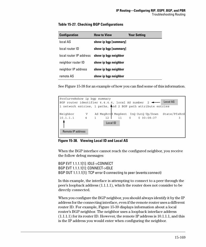
IP Routing—Configuring RIP, OSPF, BGP, and PBRTroubleshooting Routing
Table 15-27. Checking BGP Configurations
See Figure 15-38 for an example of how you can find some of this information.
Figure 15-38. Viewing Local ID and Local AS
When the BGP interface cannot reach the configured neighbor, you receive the follow debug messages:
BGP EVT 1.1.1.1[1]: IDLE->CONNECTBGP EVT 1.1.1.1[1]: CONNECT->IDLEBGP OUT 1.1.1.1[1]: TCP error 0 connecting to peer (events:connect)
In this example, the interface is attempting to connect to a peer through the peer’s loopback address (1.1.1.1), which the router does not consider to be directly connected.
When you configure the BGP neighbor, you should always identify it by the IP address for the connecting interface, even if the remote router uses a different router ID. For example, Figure 15-39 displays information about a local router’s BGP neighbor. The neighbor uses a loopback interface address (1.1.1.1) for its router ID. However, the remote IP address is 10.1.1.1, and this is the IP address you would enter when configuring the neighbor.
Configuration How to View Your Setting
local AS show ip bgp [summary]
local router ID show ip bgp [summary]
local router IP address show ip bgp neighbor
neighbor router ID show ip bgp neighbor
neighbor IP address show ip bgp neighbor
remote AS show ip bgp neighbor
ProCurve#show ip bgp summaryBGP router identifier 4.4.4.4, local AS number 21 network entries, 1 paths, and 2 BGP path attribute entries
Neighbor V AS MsgRcvd MsgSent InQ OutQ Up/Down State/PfxRcd10.1.1.1 4 1 12 11 0 0 00:08:37 3
Local AS
Local ID
Remote IP address
15-169

IP Routing—Configuring RIP, OSPF, BGP, and PBRTroubleshooting Routing
Figure 15-39. Viewing a BGP Neighbor
A BGP Interface Will Not Accept Routes. If you suspect that the filters are keeping the router from receiving routes, try comparing the routes that the BGP interface receives from a neighbor to those it actually accepts. Enter:
Syntax: show ip bgp neighbor <A.B.C.D> received-routesSyntax: show ip bgp neighbor <A.B.C.D> routes
Note any routes that display when you enter the first command that do not display when you enter the second. These routes are being filtered out. (See Figure 15-40.) You can also determine that the filter is rejecting a route, when the route does not have an asterisk (*) in front of the network address.
If the router should accept the rejected route, then the inbound filter has been misconfigured.
ProCurve#show ip bgp neighborBGP neighbor is 10.1.1.1, remote AS 1, external linkConfigured hold time is 180, keepalive interval is 60 secondsDefault minimum time between advertisement runs is 30 secondsConnections established 1; dropped 0Last reset: Never Connection ID: 2 BGP version 4, remote router ID 1.1.1.1 BGP state is Established, for 00:08:20 Negotiated hold time is 180, keepalive interval is 60 seconds Message statistics: InQ depth is 0, OutQ depth is 0 Sent Rcvd Opens: 1 1 Notifications: 0 0 Updates: 1 3 Keepalives: 8 8 Unknown: 0 0 Total: 10 12 Local host: 10.2.2.1, Local port: 1096 Foreign host: 10.1.1.1, foreign port: 179 Flags: active open
Neighbor IP addressNeighbor AS
Neighbor ID
Local IP address
Neighbor IP address
15-170

IP Routing—Configuring RIP, OSPF, BGP, and PBRTroubleshooting Routing
Figure 15-40. Comparing Accepted Routes to All Routes Received
Try removing filters from the neighbor. (See “Removing Filters” on page 15-167.) If the filter is the problem, then troubleshoot it as described in “Troubleshooting a Prefix List” on page 15-172 and “Troubleshooting a Route Map” on page 15-173.
The router also will not accept a route if the AS path includes the local AS number. If this is the problem, verify that the local AS is correct.
A BGP Interface Will Not Send Routes to a Neighbor. When remote hosts cannot reach the local network, the BGP interface may not be sending it the correct routes. View the routes the router is advertising to the neighbor by entering show ip bgp neighbor <A.B.C.D> advertised-routes.
Verify that you have configured BGP to advertise the network by viewing the running-config. Also, check outbound filters (both prefix lists and route maps) as you would inbound filters.
ProCurveSR7102dl#show ip bgp neighbor 10.1.1.1 routesBGP local router ID is 192.168.140.1, local AS is 1.Status codes: * valid, > best, i - internal, o - localOrigin codes: i - IGP, e - EGP, ? - incomplete
Network NextHop Metric LocPrf PathTotal RIB entries = 1
ProCurveSR7102dl#show ip bgp neighbor 10.1.1.1 received-routesBGP local router ID is 192.168.140.1, local AS is 1.Status codes: * valid, > best, i - internal, o - localOrigin codes: i - IGP, e - EGP, ? - incomplete
Network NextHop Metric LocPrf Path 10.0.0.0/8 10.1.1.1 2 iTotal RIB entries = 1
The router is not accepting any routes from the neighbor
The router is filtering out the route to 10.0.0.0 /8
No * indicates that the router considers the route invalid.
15-171

IP Routing—Configuring RIP, OSPF, BGP, and PBRTroubleshooting Routing
If you want a router to advertise routes it receives from one BGP neighbor to another, you must configure the AS it should add to the AS path. You configure this setting from the configuration mode context of the BGP neighbor from which the router receives the route. Enter:
Syntax: local-as <AS>
If the router still cannot send or receive routes, then it is probably having trouble connecting to the neighbor. (See “A BGP Interface Cannot Communi-cate with a Neighbor” on page 15-168.)
Troubleshooting a Prefix List
Use the following enable mode command to view a prefix list:
Syntax: show ip prefix-list [detail | summary] <listname>
The detail and summary keywords are optional and mutually exclusive. If you enter only the listname, then you can view the permit and deny statements, listed by sequence number. If you use the summary keyword, then you will see only the number of statements, their sequence numbers, and the number of these statements that include a range of valid prefixes.
Entering the detail keyword produces all the information shown by the other two commands, as well as the number of packets the router has matched to each statement. Looking for a statement that has had no hits can point you towards the statement with the misconfiguration.
If the entire list has no hits, then you may have forgotten to apply the list to the neighbor. (If you are applying the list to a route map, make sure that the map has been applied to the neighbor.) You should also verify that the list is correctly applied to either inbound or outbound data.
Figure 15-41 shows the output of a detailed command.
Figure 15-41. Viewing a Prefix List
ProCurve# show ip prefix-list detail MyListip prefix-list MyList count: 2, range entries 1, sequence 10-20 (total hit count: 50)
seq 10, deny 10.1.3.0/24 (hit count: 10)seq 20, permit 10.1.0.0/16 ge 24 le 24 (hit count: 40)
Number of statements in the list.
Number of statements that filter a range of routes. Number of routes
filtered by this statement.
15-172

IP Routing—Configuring RIP, OSPF, BGP, and PBRTroubleshooting Routing
Keep these tips in mind as you search a prefix list for misconfigurations:
■ If a statement does not include a range of prefixes, then a route must match the statement exactly in order to be selected. Make sure that the prefix length is correct.
■ Sequence numbers are important. The router stops processing the list after it finds a match. In Figure 15-41, the deny statement must have a lower sequence number than the permit statement because the route specified in the deny statement also matches the permit statement.
■ The ge and le keywords match prefixes equal to length specified, as well as those greater or lesser than the specified length. That is, the statement permit 0.0.0.0/0 le 17 will allow /17 routes.
Troubleshooting a Route Map
Enter the following enable mode command to view a route map:
Syntax: show route-map [<mapname>]
Include a name to view only that route map. If you want to see all route maps configured on the router, do not enter a mapname.
Figure 15-42. Viewing BGP Policies in a Route Map
You can view how many routes have been matches to the route map. (See Figure 15-42.) If the router does not seem to be filtering any routes, verify that you have applied the route map to the correct neighbor and as the correct policy (inbound or outbound).
ProCurve# show route-maproute-map ISP1, permit, sequence 10 Match clauses: ip address (prefix-lists): LAN1 Set clauses: community no-export metric 200 BGP Filtering matches: 5 routes Policy routing matches: 0 packets, 0 bytesroute-map ISP1, permit, sequence 20 Match clauses: ip address (prefix-lists): LAN2 Set clauses: metric 160 BGP Filtering matches: 4 routes Policy routing matches: 0 packets, 0 bytes
Criteria for selecting routes
Number of routes matches by this map entry.
Policies applied to routes
15-173

IP Routing—Configuring RIP, OSPF, BGP, and PBRTroubleshooting Routing
When examining the route map for misconfigurations keep these tips in mind:
■ If you want to apply attributes to routes filtered by an inbound route map, you must enter the set command for the attributes in the same route map entry in which you enter the match command to select permitted routes.
■ If an entry does not include a match clause, then the policy in that entry will be applied to all routes.
■ If you are using an entry to place a route in one or more communities (the set clause will read community <community>), then you should enter the send-community standard command in the BGP neighbor configu-ration mode context.
Other Common BGP Problems
Once a BGP has opened a session and exchanged routes with neighbors, two problems may arise:
■ An ISP refuses to accept the local router’s routes.
■ Your network is flooded with external traffic.
■ Routes are not being defined in the correct communities.
An ISP Router Refuses Local Routes. You should verify that your ISP allows you to advertise private routes. The ISP must support VRF.
Network Flooded with External Traffic. One of the most common uses for BGP is BGP multihoming. BGP allows you to connect to two ISPs and advertise certain routes to one and certain routes to the other.
An unintended consequence of multihoming is that the ISPs can advertise routes to each other through your local network. Your private network becomes a transit network for external traffic.
To prevent this from happening, you should configure a prefix list that adver-tises only local subnets.
Routes in Incorrect Communities. Several causes could prevent a remote neighbor from applying the correct policies to routes that you have defined as members of particular communities:
■ You did not enable the router to send community attributes to this neighbor.
Enter the send-community standard command from the BGP neighbor configuration mode context.
15-174

IP Routing—Configuring RIP, OSPF, BGP, and PBRTroubleshooting Routing
■ The BGP neighbor defines different policies for the community. Or the BGP neighbor does not accept community attributes in customer routes.
You should consult with your ISP about what communities it supports.
You may also have problems with the local policy that you have configured for communities on your router.
View route maps and examine entries that include a match clause for a community list. Then verify that the set clauses implement the correct policies for communities in this list.
You can view a community list using this enable mode command:
Syntax: show ip community-list [<listname>]
You can enter show ip bgp community-list <listname> to view the routes that match the community list.
You can monitor the communities of routes that the router receives by entering this enable mode command:
Syntax: show ip bgp community [internet | local-as | no-advertise | no-export | <1-4294967295>]
The CLI displays all routes in the specified community. Enter the command without a keyword for the community to see all routes known by the router that have a community attribute.
Monitoring and Troubleshooting PBR
After configuring PBR, you should view the policies and verify that the traffic is being sent over the correct connections.
You can view the policies applied to router interfaces with this enable mode command:
ProCurve# show ip policy
This enable mode command displays the policy applied to router traffic (if any):
ProCurve# show ip local policy
You can view the actual configured policies by viewing the route maps. Enter this enable mode command:
ProCurve# show route-map [<mapname>]
15-175

IP Routing—Configuring RIP, OSPF, BGP, and PBRTroubleshooting Routing
Figure 15-43. Viewing PBR Policies in a Route Map
The display lists entries in the route map by sequence number. The entries are further divided into match clauses, which show the criteria the map uses to select packets, and set clauses, which show the next hop address or forward-ing interface for the PBR route. (See Figure 15-43.)
You can verify that traffic can reach its destination by applying the route map to router traffic with this global configuration mode context command:
Syntax: ip local policy route-map <mapname>
First clear the route map statistics so that you can later verify that the router is matching the traffic to the route map. Enter:
ProCurve# clear route-map counters
Then send a ping to the desired destination using the extended commands so that the ping matches the criteria specified in the route map.
For example, route map entry PBR 10 (shown in Figure 15-43) selects traffic for which the Layer 3 packet size is between 150 and 200 bytes. You could enter this command from the enable mode context:
ProCurve# ping size 150
Router# show route-map
route-map PBR, permit, sequence 10 Match clauses: length 150 200 Set clauses: ip next-hop 10.10.10.254 BGP Filtering matches: 0 packets, 0 bytes Policy routing matches: 4 packets, 600 bytesroute-map PBR, permit, sequence 20 Match clauses: ip address (access-lists): 101 Set clauses: ip next-hop 10.10.10.14 BGP Filtering matches: 0 packets, 0 bytes Policy routing matches: 144 packets, 15190 bytes
Criteria for selecting traffic
Number of routes matches by this map entry
Route for selected traffic
15-176

IP Routing—Configuring RIP, OSPF, BGP, and PBRTroubleshooting Routing
You can also select a source address for ping so that you can simulate the traffic for source-based PBR. If the ping is not successful, then you should look for misconfigurations in the set clauses. Verify that specified interfaces are up and that the router’s routing table includes a route to the next-hop address.
Simply because a ping is successful does not mean that traffic used the correct interface.
View the route map by entering show route-map and verify that the pings have generated “Policy routing matches.” (See Figure 15-43.)
If the router is not matching any packets to the entries, then you should verify that the route map has been applied to the correct interface. Route maps for PBR apply to traffic received on the interface.
You should also look for misconfigurations in the match clauses. One common problem is a misconfigured ACL. See Chapter 5: Applying Access Control to
Router Interfaces for tips for troubleshooting an ACL.
Remember also that if you specify more than one type of criteria in an entry, traffic must match each specification. For example, you enter:
ProCurve(route-map)# match length 150 200ProCurve(route-map)# match ip precedence 5
This route map entry only selects packets that are both the correct size and have the correct IP precedence value.
If you are using source-based PBR only, you can use this traceroute command to determine the path the traffic is taking:
Syntax: traceroute <destination A.B.C.D> source <A.B.C.D>
Another common problem with PBR is traffic that should be routed normally is being sent over the policy-based route. In this situation, you consider whether the route map’s set commands should use the default keyword so that it only applies to traffic without another explicit route. Often this is the case when you are using the route map to route and load balance external traffic. You should also check the route map’s match clauses for misconfigu-rations. If an entry does not include a match clause, then it will select all traffic.
15-177

IP Routing—Configuring RIP, OSPF, BGP, and PBRQuick Start
Quick Start
This section provides the commands you must enter to quickly configure:
■ RIP
■ OSPF:
• internal router
• ABR
• ASBR
■ BGP
You can use more than one routing protocol. When the router learns identical routes through different routing protocols, it uses the administrative distances shown in Table 15-28 to choose between them.
This section also includes the commands for configuring a route map for PBR. Because the configuration of PBR is, by definition, dependent on your orga-nization’s policies, the quick-start commands are quite general.
Only a minimal explanation is provided. If you need additional information about any of these options, check “Contents” on page 15-1 to locate the section that contains the explanation you need.
Table 15-28. Hierarchy of Routes (Most Trusted to Least Trusted)
Route Type Default Administrative Distance
directly connected 0
static 1
BGP • 20 for external routes• 200 for internal and local routes
OSPF 110
RIP v1 and v2 120
15-178

IP Routing—Configuring RIP, OSPF, BGP, and PBRQuick Start
RIP Routing
1. Move to the global configuration mode context and access the RIP con-figuration mode context.
ProCurve(config)# router rip
2. Specify the RIP version.
Syntax: version [1 | 2]
3. Advertise local subnets. Interfaces on these subnets will send and receive RIP updates.
Syntax: network <network A.B.C.D> <subnet mask>
Note that you enter the subnet mask, not wildcard bits. For example:
ProCurve(config-rip)# network 192.168.1.0 255.255.255.0
4. Add the WAN interfaces. For example:
ProCurve(config-rip)# network 10.1.1.0 255.255.255.252
5. Specify any passive interfaces, which receive RIP updates but do not send them. (For example, you might not want an interface that connects to an external network to send RIP updates. Or you might want to configure a loopback interface as a passive interface to minimize redundant updates.)
Syntax: passive-interface <interface ID>
OSPF Routing
You should first determine whether the router is:
■ an internal router (a router in only one area)
■ an ABR (a router that has interfaces in more than one area)
■ an ASBR (a router than connects to an external network)
See Figure 15-44 for a simplified illustration of an OSPF network.
15-179
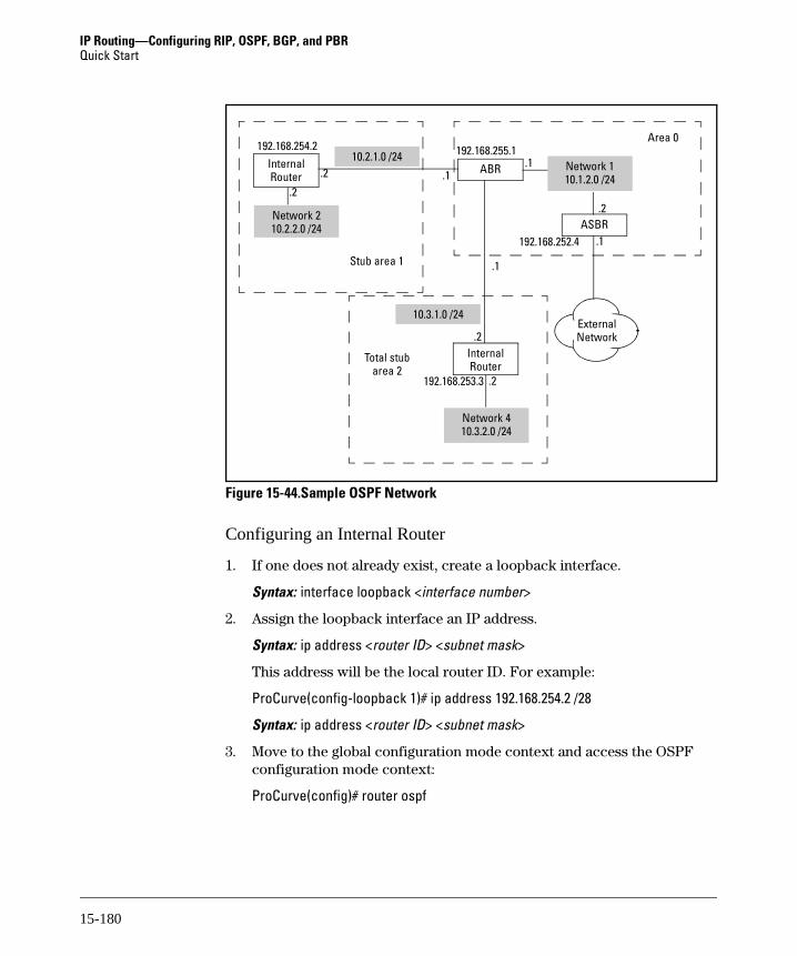
IP Routing—Configuring RIP, OSPF, BGP, and PBRQuick Start
Figure 15-44.Sample OSPF Network
Configuring an Internal Router
1. If one does not already exist, create a loopback interface.
Syntax: interface loopback <interface number>
2. Assign the loopback interface an IP address.
Syntax: ip address <router ID> <subnet mask>
This address will be the local router ID. For example:
ProCurve(config-loopback 1)# ip address 192.168.254.2 /28
Syntax: ip address <router ID> <subnet mask>
3. Move to the global configuration mode context and access the OSPF configuration mode context:
ProCurve(config)# router ospf
Area 0
ABR
Stub area 1
Internal Router
Total stub area 2
Internal Router
ASBR
External Network
Network 4 10.3.2.0 /24
10.3.1.0 /24
.2
.1
.1
10.2.1.0 /24.2 Network 1
10.1.2.0 /24.1
Network 2 10.2.2.0 /24
.2
192.168.254.2 192.168.255.1
.2
.1
.2
192.168.252.4
192.168.253.3
15-180

IP Routing—Configuring RIP, OSPF, BGP, and PBRQuick Start
4. Specify the network and area of each interface that should run OSPF:
Syntax: network <network A.B.C.D> <wildcard bits> area <area ID>
For example:
ProCurve(config-ospf)# network 10.2.0.0 0.0.255.255 area 1
5. Specify that this area is a stub area:
Syntax: area <area ID> stub
Configuring an ABR
1. If one does not already exist, create a loopback interface.
Syntax: interface loopback <interface number>
2. Assign the loopback interface an IP address.
Syntax: ip address <A.B.C.D> <subnet mask>
This address should be the local router ID. For example:
ProCurve(config-loopback 1)# ip address 192.168.255.1 /28
3. Move to the global configuration mode context and access the OSPF configuration mode context.
ProCurve(config)# router ospf
4. Enable OSPF on the WAN interfaces. If the connected LANs run OSPF, also enable OSPF for these subnets. Specify the network and area in which each interface resides.
Syntax: network <network A.B.C.D> <wildcard bits> area <area ID>
For example:
ProCurve(config-ospf)# network 10.1.0.0 0.0.255.255 area 0ProCurve(config-ospf)# network 10.2.0.0 0.0.255.255 area 1ProCurve(config-ospf)# network 10.3.0.0 0.0.255.255 area 2
5. If necessary, you can redistribute connected routes for connected net-works not participating in OSPF.
ProCurve(config-ospf)# redistribute connected
15-181

IP Routing—Configuring RIP, OSPF, BGP, and PBRQuick Start
6. If the ABR will be sending summary LSAs, define the address ranges for these summaries. Select which routes the ABR should advertise and which it should not.
Syntax: area <area ID> range <network A.B.C.D> <subnet mask> [advertise | not-advertise]
If you do not select an option for advertising, the router will automatically advertise the summary. For example:
ProCurve(config-ospf)# area 0 range 10.1.0.0 255.255.0.0ProCurve(config-ospf)# area 1 range 10.2.0.0 255.255.0.0ProCurve(config-ospf)# area 2 range 10.3.0.0 255.255.0.0 not-advertise
7. Specify the stub areas, which receive a default route and summary routes for inter-area traffic.
Syntax: area <area ID> stub
8. Specify the total stub areas, which receive only a default route.
Syntax: area <area ID> stub no-summary
Configuring an ASBR
1. If one does not already exist, create a loopback interface.
Syntax: interface loopback <interface number>
2. Assign the loopback interface an IP address.
Syntax: ip address <A.B.C.D> <subnet mask>
This address should be the local router ID. For example:
ProCurve(config-loopback 1)# ip address 192.168.255.4 /28
Syntax: ip address <router ID> <subnet mask>
3. Enable the external routing protocol. (See, for example, the Quick Start for BGP or RIP.)
4. Access the OSPF configuration mode context.
ProCurve(config)# router ospf
5. Enable OSPF on the interface that connects to other routers in the internal network.
Syntax: network <network A.B.C.D> <wildcard bits> area <area ID>
For example:
ProCurve(config-ospf)# network 10.1.2.0 0.0.0.255 area 0
15-182

IP Routing—Configuring RIP, OSPF, BGP, and PBRQuick Start
6. Force the router to advertise a default route for external routes.
Syntax: default-information-originate [always] [metric <value>] [metric <type>]
If the router does not have its own default route, use the always option. Specifying a metric or metric type is optional. (By default, the metric is 0 and the metric type is 2.) For example, enter:
ProCurve(config-ospf)# default-information-originate always
Configuring BGP
1. Enable the internal routing protocol. (See Quick Starts for RIP and OSPF ASBRs.)
2. Move to the global configuration mode context and enable BGP. Also, specify the local AS.
Syntax: router bgp <local AS>
For example:
ProCurve(config)# router bgp 2
3. Specify the network or range of networks that the BGP interface(s) should advertise. This might be only a public network. Or, if your have agreed with your ISP that it will transit routes between remote networks (for example, VPN sites), the network might be a range of private subnets.
Syntax: network <network A.B.C.D> mask <subnet mask>
For example:
ProCurve(config-bgp)# network 10.1.0.0 mask 255.255.0.0
4. The routing table may not include an entry to the range of networks you specified in step 2. If necessary, add a null route to the routing table. For example:
ProCurve(config)# ip route 10.1.0.0 255.255.0.0 null 0
5. Return to the BGP configuration mode context and set the local router ID.
Syntax: bgp router-id <A.B.C.D>
This ID should be the IP address on the interface that communicates with the neighbor. (It can also be the IP address of a loopback interface used as the update source.) For example:
ProCurve(config-bgp)# bgp router-id 1.1.1.2
15-183

IP Routing—Configuring RIP, OSPF, BGP, and PBRQuick Start
6. Configure a BGP neighbor.
Syntax: neighbor <neighbor A.B.C.D>
Specify the neighbor’s IP address as its ID. For example:
ProCurve(config-bgp)# neighbor 1.1.1.1
7. Specify the remote AS.
Syntax: remote-as <remote AS>
8. If so desired, specify a loopback interface as the update source, which can add stability to the BGP session. You can alternatively specify any router interface as the source.
Syntax: update-source <interface ID>
9. If the router connects to more than one neighbor, repeat steps 6 and 7.
Configuring PBR
1. Determine what criteria the router should use for routing packets. The ProCurve Secure Router can route packets based on:
• source IP address
• source and destination IP address
• application data
• IP precedence value
• DiffServ value
• payload size
2. If the router will be routing traffic based on source IP address only, you must configure a standard ACL to select the traffic.
a. Create the ACL.
Syntax: ip access-list standard <listname>b. Use permit statements to specify the hosts, networks, or range of
networks from which the traffic that is to be routed using PBR will originate. If necessary, first enter a deny statement to exclude one or more addresses from a permitted range. Use this command to add a statement to the list:
Syntax: [deny | permit] [any | host <A.B.C.D> | <A.B.C.D> <wildcard bits>]
15-184

IP Routing—Configuring RIP, OSPF, BGP, and PBRQuick Start
3. If the router will be routing traffic according to source and destination IP address or application data, you must create an extended ACL.
a. Create the ACL.
Syntax: ip access-list extended <listname>b. Use permit statements to specify allowed traffic and deny statements
to exclude traffic.
Syntax: [deny | permit] ip [any | host <A.B.C.D> | <A.B.C.D> <wildcard bits>] [any | host <A.B.C.D> | <A.B.C.D> <wildcard bits>]
For the first address, enter the source of traffic to be routed using PBR. For the second address, enter the traffic’s ultimate destination.
c. If the router should route packets based on application data, then the permit statement that you enter must include the protocol for the application and source or destination port, or both. Use this com-mand:
Syntax: [permit | deny] <protocol> [any | host <A.B.C.D> | <A.B.C.D> <wild-card bits>] [eq <port> | gt <port> | lt <port> | range <first port> <last port> | neq <port>] [any | host <A.B.C.D> | <A.B.C.D> <wildcard bits>] [eq <port> | gt <port> | lt <port> | range <first port> <last port> | neq <port>]
4. Create a route map entry. From the global configuration mode context, enter:
Syntax: route-map <mapname> <sequence number>
5. Specify the traffic that the router should use PBR to route. Use match commands to configure the criteria you determined in step 1. If you enter more than one type of match command, then traffic must match all the criteria. If you do not enter a match command, then all traffic will match the route map entry.
a. To route traffic based on source IP address, source and destination address, or application data, specify the ACL that you configured in step 2 or step 3.
Syntax: match ip address <listname>b. To route traffic based on IP precedence value, enter this command:
Syntax: match ip precedence [critical | flash | flash-override | immediate | internet | network | priority | routine | <0-7>]
Select the value by number or by keyword. Packets should be already marked with the value by devices within your LAN.
15-185

IP Routing—Configuring RIP, OSPF, BGP, and PBRQuick Start
c. To route traffic based on DiffServ value, enter this command:
Syntax: match ip dscp [af11 | af12 | af13 | af 21 | af 22 | af23 | af31 | af 32 | af 33 | af 41 | af42 | af43 | cs1 | cs2 | cs3 | cs4 | cs5 | cs6 | cs7 | default | ef | <0-63>]
You can select default traffic (no DiffServ value set); traffic in a CS PHB, a AF PHB, or the EF PHB; or traffic marked with any DiffServ value defined within your network.
d. To route traffic based on the payload size, enter this command:
Syntax: match length <minimum length in bytes> <maximum length in bytes>
6. Set the next hop address or the forwarding interface for the policy-based route:
a. To set a next hop address, enter this command:
Syntax: set ip [default] next-hop <A.B.C.D> <secondary A.B.C.D>
If you enter the default keyword, then the router will only use this policy-based route to forward a packet when its routing table does not include an explicit route for the packet’s destination.
You can enter more than one next-hop address in the command to provide a backup route. The router first attempts to route traffic to the first address listed and then tries the others.
b. To set a forwarding interface for the policy-based route, enter this command:
Syntax: set [default] interface <interface ID> <secondary interface ID>
You can specify multiple possible forwarding interfaces. Again, the optional default keyword forces the router to use its routing table to forward a packet when this table contains an explicit route for the packet’s destination.
c. You can enter more than one set command. The router will attempt to route traffic as follows:– first, to any adjacent next-hop address– then, through any forwarding interface– then, to any default next-hop address– last, through any default forwarding interface
7. You can configure multiple route map entry with the same name to establish multiple policy-based routes for traffic arriving on an interface. Repeat the steps above.
15-186

IP Routing—Configuring RIP, OSPF, BGP, and PBRQuick Start
8. Apply the route map to LAN interfaces to enable PBR for traffic outbound to the WAN. (This is the typical application.) You can also apply route maps to any logical interface. Move to the Ethernet or logical interface configuration mode context and enter this command:
Syntax: ip policy route-map <mapname>
N o t e An interface must have an IP address in order for you to assign a route map to it.
15-187

IP Routing—Configuring RIP, OSPF, BGP, and PBRQuick Start
15-188