Embed Size (px)
Citation preview
ARTICLE IN PRESS
Fire Safety Journal 44 (2009) 894–900
Contents lists available at ScienceDirect
Fire Safety Journal
0379-71
doi:10.1
� Corr
E-m
journal homepage: www.elsevier.com/locate/firesaf
Investigation on the ability of glowing firebrands deposited within crevices toignite common building materials
Samuel L. Manzello �, Seul-Hyun Park, Thomas G. Cleary
Fire Research Division, Building and Fire Research Laboratory (BRFL), National Institute of Standards and Technology (NIST), 100 Bureau Drive, Stop 8662,
Bldg. 224, Room A361, Gaithersburg, MD 20899, USA
a r t i c l e i n f o
Article history:
Received 30 July 2008
Accepted 13 May 2009Available online 11 June 2009
Keywords:
Wildland–urban interface (WUI) fires
Firebrands
Ignition
Fuel beds
12/$ - see front matter Published by Elsevier
016/j.firesaf.2009.05.001
esponding author. Tel.: +1301975 6891; fax:
ail address: [email protected] (S.L. Manzello
a b s t r a c t
A series of experiments was conducted to determine the range of conditions that glowing firebrands
may ignite common building materials. The surface temperature of glowing firebrands burning under
different applied airflow was quantified using an infrared camera. As the applied airflow was increased,
the surface temperature of glowing firebrands was observed to increase. A crevice was constructed
using plywood and oriented strand board (OSB) and the angle was varied to investigate the influence
that this parameter has on promoting ignition after contact with glowing firebrands. The number of
firebrands deposited within the constructed crevices was varied. Single firebrands were unable to ignite
the materials used in this study over a range of applied airflows. For the tightest fuel bed angle of 601,
the glowing firebrands deposited on the fuel bed always resulted in smoldering ignition. For plywood,
contact with glowing firebrands produced smoldering ignition followed by a transition to flaming
ignition. At the fuel bed angle of 901, no definitive ignition behavior was observed for either material;
different ignition criteria (either no ignition or smoldering ignition) were observed under identical
experimental conditions. As the fuel bed angle was increased up to 1351, ignition never occurred for
both test fuel beds. For a given airflow and fuel bed material, the ignition delay time was observed to
increase as the fuel bed angle was increased. A large difference was observed in the ignition delay time
for plywood and OSB at a fuel bed angle of 901. Based on these ignition results, the critical angle for
ignition exists between 901 and 1351 at a given airflow. These results clearly demonstrate that
firebrands are capable of igniting common building materials.
Published by Elsevier Ltd.
1. Introduction
The 2007 Southern California fires underscore the difficulty ofthe problem of structure ignition in wildland–urban Interface(WUI) fires. Firefighting resources were overwhelmed and simplycould not handle catastrophic structure ignition in these fires.Similarly, in 2003, WUI fires near San Diego, California, displacednearly 100,000 people and destroyed over 3000 homes, leading toover $2B in insured losses [1].
Fire risk to WUI communities is currently mitigated by eitherreducing wildland fuel loading or following a number of home-owner risk reduction practices (e.g., Firewise). The various fueltreatment methods used are based on very limited scientificstudy, leaving their effectiveness largely unproven, especially withregard to preventing structure ignition. Most of these riskreduction practices follow rule-based and empirically determined
Ltd.
+1301975 4052.
).
checklists that lack testing and are not the result of a coordinatedscientific-based effort.
Anecdotal evidence suggests that spotting is the major sourceof structural ignition in WUI fires. Spot fires are defined as newfires that propagate away from the main fire line due to loftedfirebrands. An understanding on how these lofted flaming/glowing firebrands can ignite surrounding fuel beds is necessaryto mitigate fire spread in communities [1,2]. The firebrandproblem is not trivial and consists of various aspects includingthe production of combustible products from vegetation andstructures, subsequent transport through the atmosphere, and theultimate ignition of fuels. Most firebrand studies, be theyexperimental or numerical in nature, have focused on firebrandtransport [3–11], attempting to determine the potential spottingdistance of firebrands [5,8–10].
One of the purported mechanisms of structure ignition in WUIfires is the trapping of firebrands within small crevices withinstructures. Unfortunately, very few studies have investigated therange of conditions under which it is possible to ignite thesematerials by firebrands. Dowling [12] burned wood cribs and theresultant firebrands were collected and deposited into a 10 mm
ARTICLE IN PRESS
S.L. Manzello et al. / Fire Safety Journal 44 (2009) 894–900 895
gap between the wood bridge members (deck plank and gravelbeam). It was observed that 7 g of firebrands was able to producesmoldering ignition of the wood members within the 10 mm gap.The state of the firebrands upon deposition into 10 mm gaps, i.e.,glowing or flaming, was not specified.
In early work, Waterman and Takata [13] investigated fire-brand impact upon a variety of ignitable materials. Thewind speed was altered in these tests. A radiant flux was appliedin conjunction with firebrand impact to ascertain materialignitability. Ignition probabilities were reported for thevarious materials considered. Ignitions were observed from38-mm-long firebrand (unassisted – no radiant flux) in contactwith most of the building materials tested. Firebrands smallerthan 38 mm were unable to ignite the building materialsconsidered.
As part of a larger study of various materials, Manzello et al.[14] deposited both glowing and flaming firebrands onto cedarcrevices of a fixed angle (901), but with varying moisture content.Cedar was selected since some types of shingles are actuallyconstructed of cedar. Glowing firebrands were unable to ignitecedar crevices under the conditions tested. A critical flux of threeflaming firebrands was required to achieve ignition for multipleflaming firebrands into moist cedar crevices. When the con-structed cedar crevice samples were dried, it was observed thatonly one 50 mm flaming firebrand was required to produceignition. Additional building materials were not considered inthat study and detailed findings regarding critical angles forignition were not determined.
BlowerHeater
Test Section
90cm 120cm 220
71cm
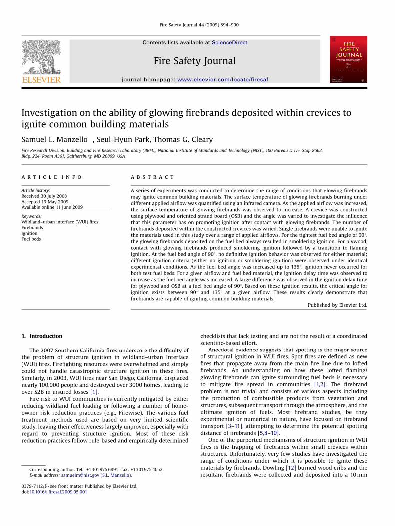
Fig. 1. Schematic of the fire emulator/detector evaluator (
House Air Supply
House Air Supply
Solenoid Valve
Solenoid Valve
SolenoValv
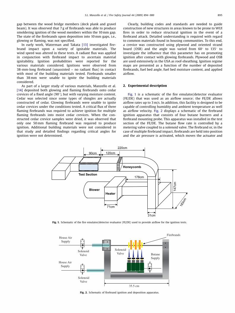
Fig. 2. Schematic of firebrand ignit
Clearly, building codes and standards are needed to guideconstruction of new structures in areas known to be prone to WUIfires in order to reduce structural ignition in the event of afirebrand attack. Detailed understanding is required with regardto common materials found in housing communities. To this end,a crevice was constructed using plywood and oriented strandboard (OSB) and the angle was varied from 601 to 1351 toinvestigate the influence that this parameter has on promotingignition after contact with glowing firebrands. Plywood and OSBare used extensively in the USA as roof-sheathing. Ignition regimemaps are presented as a function of the number of depositedfirebrands, fuel bed angle, fuel bed moisture content, and appliedairflow.
2. Experimental description
Fig. 1 is a schematic of the fire emulator/detector evaluator(FE/DE) that was used as an airflow source; the FE/DE allowsairflow rates up to 3 m/s. In addition, this facility is designed to becapable of controlling humidity and ambient temperature as wellas airflow velocity. Fig. 2 displays a schematic of the firebrandignition apparatus that consists of four butane burners and afirebrand mounting probe. This apparatus was installed in the testsection of the FE/DE. The butane flow rate is controlled by ametering valve coupled to a solenoid valve. The firebrand or, in thecase of multiple firebrand impact, firebrands are held into positionand the air pressure is activated, which moves the actuator and
Honeycomb
cm
178cm
31cm
147c
m
183c
m
FE/DE) used to provide airflow for the ignition tests.
Firebrands
35.5 cm
id e Butane
Supply
ion and deposition apparatus.
ARTICLE IN PRESS
Table 1Glowing firebrand ignition data.
Air flow
(m/s)
Number of
firebrands
Fuel bed
angle (1)
Fuel bed
material
Ignition
type
1.3 4 60 Ply wood NI2.4 4 60 Ply wood SI to FI2.4 4 60 OSB SI or SI to FI2.4 3 60 Ply wood NI or SI2.4 3 60 OSB NI or SI2.4 2 60 Ply wood NI2.4 2 60 OSB NI2.4 4 90 Ply wood NI or SI2.4 4 90 OSB NI or SI2.4 4 135 Ply wood NI2.4 4 135 OSB NI
NI: No ignition; SI: smoldering ignition; FI: flaming ignition; SI to FI: transition
from SI to FI.
S.L. Manzello et al. / Fire Safety Journal 44 (2009) 894–900896
clamps the firebrand(s) into position. The retraction of the burnerupon ignition and the free-burn time of the firebrands arecomputer controlled, which ensures repeatability. Each butaneburner was designed to be switched on or off, depending on thenumber of firebrands needed for the particular experiment.Further details of the apparatus, including the FE/DE, aredescribed elsewhere [14–16].
Firebrands were constructed by machining wood into sectionsof uniform geometry. For the present study, firebrands weresimulated as cylinders (10 mm in diameter with a length of76 mm) determined from the measured firebrand size distribu-tions generated from real-scale tree burns [16]. Ponderosa pinewas selected as the wood type for these experiments. After thecylinders were machined, they were stored in a conditioningroom prior to the experiments (21 1C, 50% relative humidity) for2 weeks.
Two different materials were used as test fuel beds for theignition studies: (1) plywood and (2) oriented strand board. Boththese materials are commonly employed as base materials inroofing assemblies in the USA. In the USA, there has been adramatic shift to the use of OSB; historically plywood was thedominant material used in roof-sheathing [17]. The reasons forthis are primarily economic in nature; OSB is manufactured fromsmaller trees as compared to plywood and consists primarily ofwood fragments.
The plywood and OSB pieces were cut into rectangular sectionsof 206 mm�88 mm. The thickness of all samples was fixed at9 mm. The moisture content of these materials was varied fromoven dry to 11%. The moisture content was determined by ovendrying the samples. It was found that 3 h of oven drying at 104 1Cwas sufficient to remove all the moisture in the plywood and OSBsamples. The firebrand ignition process and release onto thetarget fuel beds were captured using a CCD camera coupled to azoom lens.
Firebrands were ignited by exposing them in a verticalorientation, parallel to the burner flow field, for a fixed durationand allowed to free burn. When the firebrands were alignedhorizontally, the burners were unable to ignite them completely;the flame would not engulf the entire firebrand. Under airflowconditions, the firebrands were ignited under low flow conditionsand the airflow was ramped up as soon as the ignition process wasover. The ignition time for the 10 mm firebrands was 70 s. Theseignition times were selected in order to completely engulf thefirebrand in flame. Under no airflow conditions, the firebrandremained in a flaming state. When airflow was introduced, theairflow blew off the envelope flame from the leading edge ofthe firebrand and gradually blew the flame off the backside of thefirebrand. After the flame was blown off, a glowing firebrandresulted. A similar result was observed using Douglas-Fircylinders [16]. The ignition propensity of the plywood and OSBfuel beds was determined only under conditions of glowingfirebrand deposition.
q"FB
q"conv.m"Lv
Fuel Bed
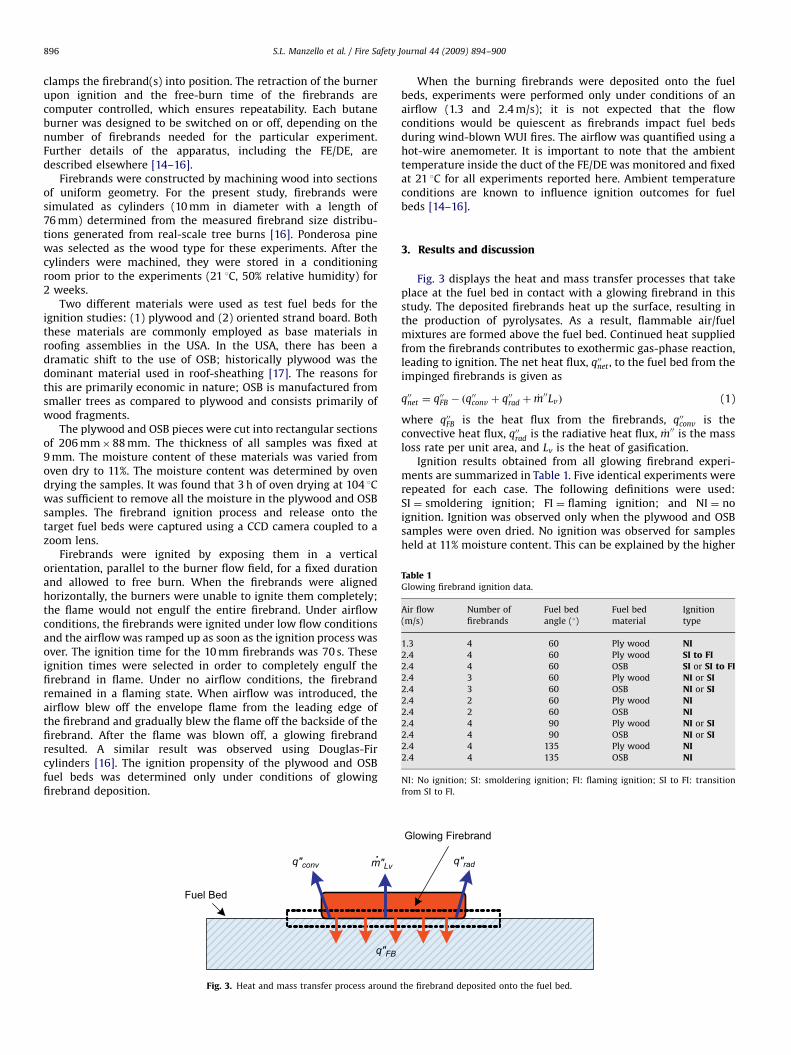
Fig. 3. Heat and mass transfer process around
When the burning firebrands were deposited onto the fuelbeds, experiments were performed only under conditions of anairflow (1.3 and 2.4 m/s); it is not expected that the flowconditions would be quiescent as firebrands impact fuel bedsduring wind-blown WUI fires. The airflow was quantified using ahot-wire anemometer. It is important to note that the ambienttemperature inside the duct of the FE/DE was monitored and fixedat 21 1C for all experiments reported here. Ambient temperatureconditions are known to influence ignition outcomes for fuelbeds [14–16].
3. Results and discussion
Fig. 3 displays the heat and mass transfer processes that takeplace at the fuel bed in contact with a glowing firebrand in thisstudy. The deposited firebrands heat up the surface, resulting inthe production of pyrolysates. As a result, flammable air/fuelmixtures are formed above the fuel bed. Continued heat suppliedfrom the firebrands contributes to exothermic gas-phase reaction,leading to ignition. The net heat flux, q00net , to the fuel bed from theimpinged firebrands is given as
q00net ¼ q00FB � ðq00conv þ q00rad þ _m00LvÞ (1)
where q00FB is the heat flux from the firebrands, q00conv is theconvective heat flux, q00rad is the radiative heat flux, _m00 is the massloss rate per unit area, and Lv is the heat of gasification.
Ignition results obtained from all glowing firebrand experi-ments are summarized in Table 1. Five identical experiments wererepeated for each case. The following definitions were used:SI ¼ smoldering ignition; FI ¼ flaming ignition; and NI ¼ noignition. Ignition was observed only when the plywood and OSBsamples were oven dried. No ignition was observed for samplesheld at 11% moisture content. This can be explained by the higher
q"rad
Glowing Firebrand
the firebrand deposited onto the fuel bed.
ARTICLE IN PRESS
150
200
250
300
350
0
T.C. measurement
Emissivity = 0.70
Emissivity = 0.65
Emissivity = 0.60
Tem
pera
ture
[°C
]
Time [s]
2 4 6 8 10 12
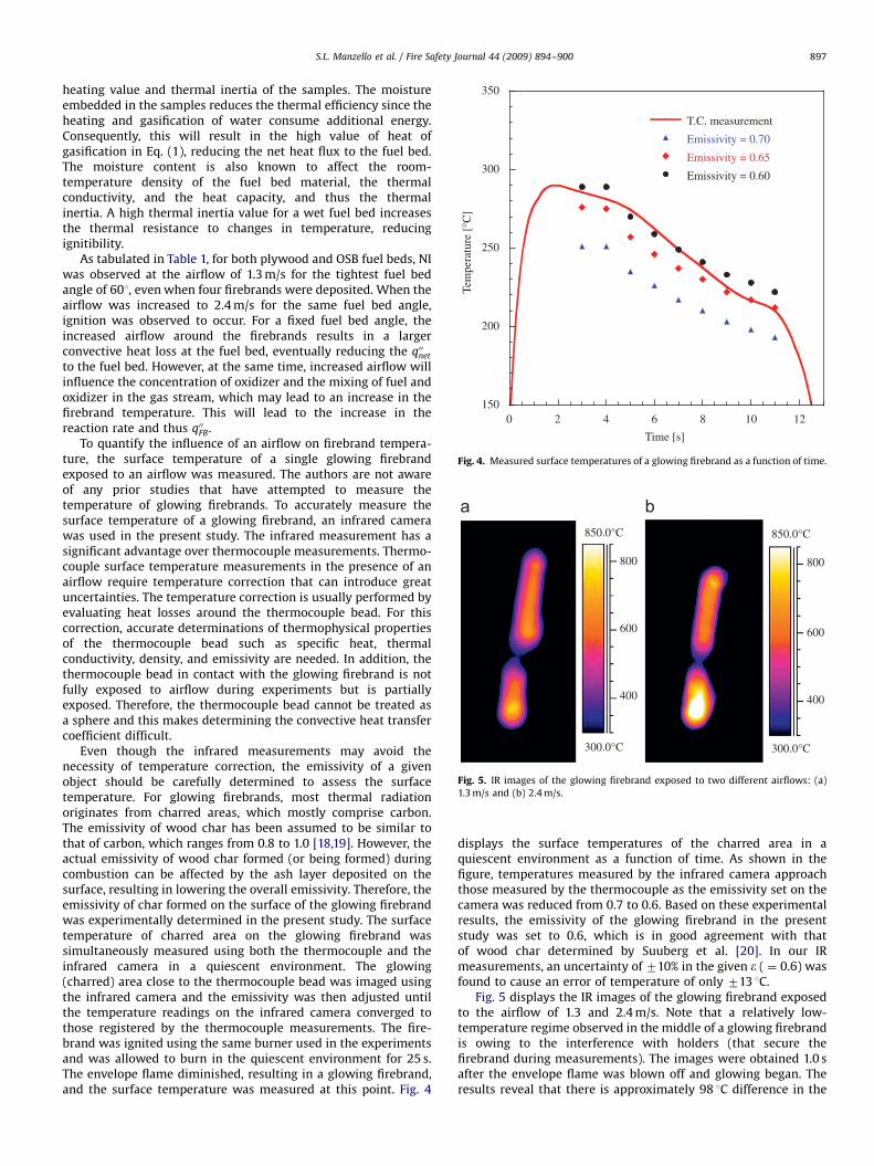
Fig. 4. Measured surface temperatures of a glowing firebrand as a function of time.
850.0°C
800
600
400
300.0°C
850.0°C
800
600
400
300.0°C
Fig. 5. IR images of the glowing firebrand exposed to two different airflows: (a)
1.3 m/s and (b) 2.4 m/s.
S.L. Manzello et al. / Fire Safety Journal 44 (2009) 894–900 897
heating value and thermal inertia of the samples. The moistureembedded in the samples reduces the thermal efficiency since theheating and gasification of water consume additional energy.Consequently, this will result in the high value of heat ofgasification in Eq. (1), reducing the net heat flux to the fuel bed.The moisture content is also known to affect the room-temperature density of the fuel bed material, the thermalconductivity, and the heat capacity, and thus the thermalinertia. A high thermal inertia value for a wet fuel bed increasesthe thermal resistance to changes in temperature, reducingignitibility.
As tabulated in Table 1, for both plywood and OSB fuel beds, NIwas observed at the airflow of 1.3 m/s for the tightest fuel bedangle of 601, even when four firebrands were deposited. When theairflow was increased to 2.4 m/s for the same fuel bed angle,ignition was observed to occur. For a fixed fuel bed angle, theincreased airflow around the firebrands results in a largerconvective heat loss at the fuel bed, eventually reducing the q00net
to the fuel bed. However, at the same time, increased airflow willinfluence the concentration of oxidizer and the mixing of fuel andoxidizer in the gas stream, which may lead to an increase in thefirebrand temperature. This will lead to the increase in thereaction rate and thus q00FB.
To quantify the influence of an airflow on firebrand tempera-ture, the surface temperature of a single glowing firebrandexposed to an airflow was measured. The authors are not awareof any prior studies that have attempted to measure thetemperature of glowing firebrands. To accurately measure thesurface temperature of a glowing firebrand, an infrared camerawas used in the present study. The infrared measurement has asignificant advantage over thermocouple measurements. Thermo-couple surface temperature measurements in the presence of anairflow require temperature correction that can introduce greatuncertainties. The temperature correction is usually performed byevaluating heat losses around the thermocouple bead. For thiscorrection, accurate determinations of thermophysical propertiesof the thermocouple bead such as specific heat, thermalconductivity, density, and emissivity are needed. In addition, thethermocouple bead in contact with the glowing firebrand is notfully exposed to airflow during experiments but is partiallyexposed. Therefore, the thermocouple bead cannot be treated asa sphere and this makes determining the convective heat transfercoefficient difficult.
Even though the infrared measurements may avoid thenecessity of temperature correction, the emissivity of a givenobject should be carefully determined to assess the surfacetemperature. For glowing firebrands, most thermal radiationoriginates from charred areas, which mostly comprise carbon.The emissivity of wood char has been assumed to be similar tothat of carbon, which ranges from 0.8 to 1.0 [18,19]. However, theactual emissivity of wood char formed (or being formed) duringcombustion can be affected by the ash layer deposited on thesurface, resulting in lowering the overall emissivity. Therefore, theemissivity of char formed on the surface of the glowing firebrandwas experimentally determined in the present study. The surfacetemperature of charred area on the glowing firebrand wassimultaneously measured using both the thermocouple and theinfrared camera in a quiescent environment. The glowing(charred) area close to the thermocouple bead was imaged usingthe infrared camera and the emissivity was then adjusted untilthe temperature readings on the infrared camera converged tothose registered by the thermocouple measurements. The fire-brand was ignited using the same burner used in the experimentsand was allowed to burn in the quiescent environment for 25 s.The envelope flame diminished, resulting in a glowing firebrand,and the surface temperature was measured at this point. Fig. 4
displays the surface temperatures of the charred area in aquiescent environment as a function of time. As shown in thefigure, temperatures measured by the infrared camera approachthose measured by the thermocouple as the emissivity set on thecamera was reduced from 0.7 to 0.6. Based on these experimentalresults, the emissivity of the glowing firebrand in the presentstudy was set to 0.6, which is in good agreement with thatof wood char determined by Suuberg et al. [20]. In our IRmeasurements, an uncertainty of 710% in the given e ( ¼ 0.6) wasfound to cause an error of temperature of only 713 1C.
Fig. 5 displays the IR images of the glowing firebrand exposedto the airflow of 1.3 and 2.4 m/s. Note that a relatively low-temperature regime observed in the middle of a glowing firebrandis owing to the interference with holders (that secure thefirebrand during measurements). The images were obtained 1.0 safter the envelope flame was blown off and glowing began. Theresults reveal that there is approximately 98 1C difference in the
ARTICLE IN PRESS
S.L. Manzello et al. / Fire Safety Journal 44 (2009) 894–900898
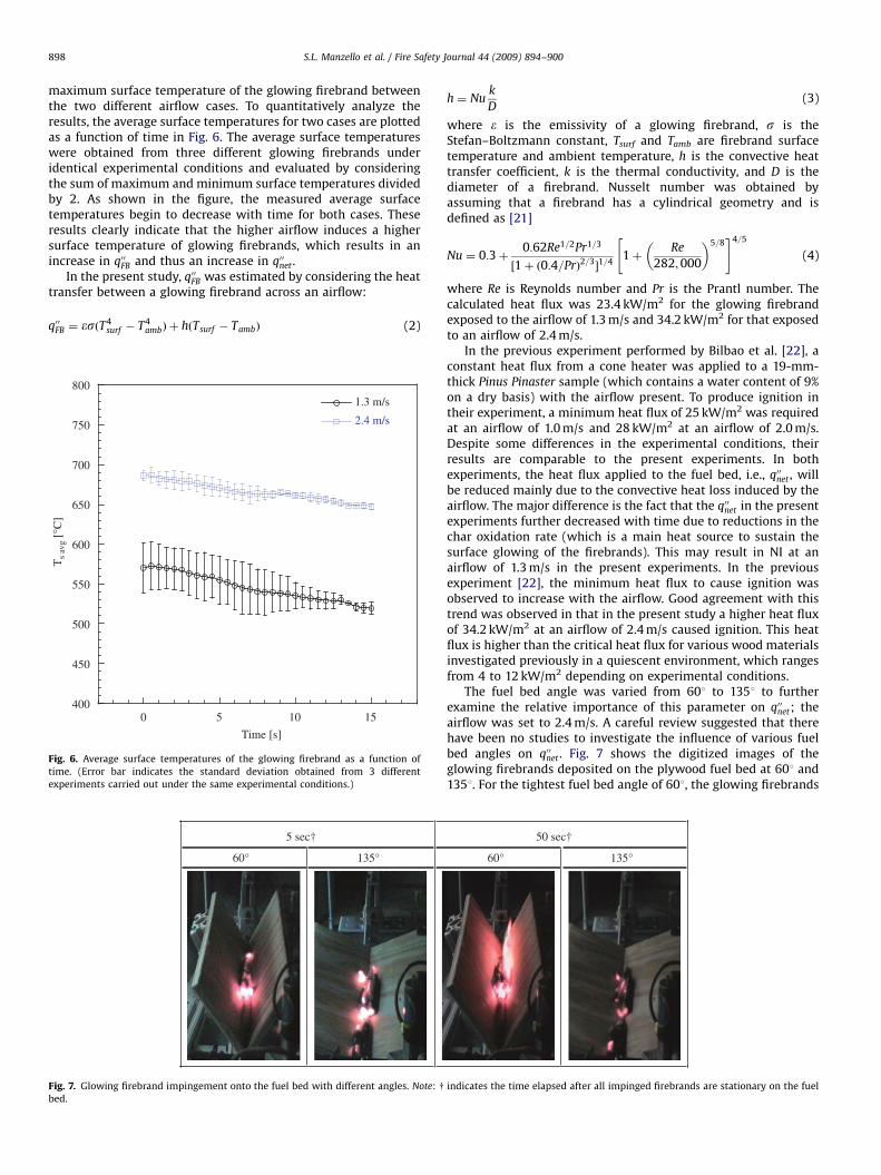
maximum surface temperature of the glowing firebrand betweenthe two different airflow cases. To quantitatively analyze theresults, the average surface temperatures for two cases are plottedas a function of time in Fig. 6. The average surface temperatureswere obtained from three different glowing firebrands underidentical experimental conditions and evaluated by consideringthe sum of maximum and minimum surface temperatures dividedby 2. As shown in the figure, the measured average surfacetemperatures begin to decrease with time for both cases. Theseresults clearly indicate that the higher airflow induces a highersurface temperature of glowing firebrands, which results in anincrease in q00FB and thus an increase in q00net .
In the present study, q00FB was estimated by considering the heattransfer between a glowing firebrand across an airflow:
q00FB ¼ �sðT4surf � T4
ambÞ þ hðTsurf � TambÞ (2)
400
450
500
550
600
650
700
750
800
0
1.3 m/s
2.4 m/s
Time [s]
Ts
avg
[°C
]
5 10 15
Fig. 6. Average surface temperatures of the glowing firebrand as a function of
time. (Error bar indicates the standard deviation obtained from 3 different
experiments carried out under the same experimental conditions.)
5 sec†
60° 135°
Fig. 7. Glowing firebrand impingement onto the fuel bed with different angles. Note: y
bed.
h ¼ Nuk
D(3)
where e is the emissivity of a glowing firebrand, s is theStefan–Boltzmann constant, Tsurf and Tamb are firebrand surfacetemperature and ambient temperature, h is the convective heattransfer coefficient, k is the thermal conductivity, and D is thediameter of a firebrand. Nusselt number was obtained byassuming that a firebrand has a cylindrical geometry and isdefined as [21]
Nu ¼ 0:3þ0:62Re1=2Pr1=3
½1þ ð0:4=PrÞ2=3�1=4
1þRe
282;000
� �5=8" #4=5
(4)
where Re is Reynolds number and Pr is the Prantl number. Thecalculated heat flux was 23.4 kW/m2 for the glowing firebrandexposed to the airflow of 1.3 m/s and 34.2 kW/m2 for that exposedto an airflow of 2.4 m/s.
In the previous experiment performed by Bilbao et al. [22], aconstant heat flux from a cone heater was applied to a 19-mm-thick Pinus Pinaster sample (which contains a water content of 9%on a dry basis) with the airflow present. To produce ignition intheir experiment, a minimum heat flux of 25 kW/m2 was requiredat an airflow of 1.0 m/s and 28 kW/m2 at an airflow of 2.0 m/s.Despite some differences in the experimental conditions, theirresults are comparable to the present experiments. In bothexperiments, the heat flux applied to the fuel bed, i.e., q00net , willbe reduced mainly due to the convective heat loss induced by theairflow. The major difference is the fact that the q00net in the presentexperiments further decreased with time due to reductions in thechar oxidation rate (which is a main heat source to sustain thesurface glowing of the firebrands). This may result in NI at anairflow of 1.3 m/s in the present experiments. In the previousexperiment [22], the minimum heat flux to cause ignition wasobserved to increase with the airflow. Good agreement with thistrend was observed in that in the present study a higher heat fluxof 34.2 kW/m2 at an airflow of 2.4 m/s caused ignition. This heatflux is higher than the critical heat flux for various wood materialsinvestigated previously in a quiescent environment, which rangesfrom 4 to 12 kW/m2 depending on experimental conditions.
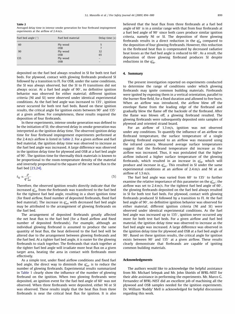
The fuel bed angle was varied from 601 to 1351 to furtherexamine the relative importance of this parameter on q00net; theairflow was set to 2.4 m/s. A careful review suggested that therehave been no studies to investigate the influence of various fuelbed angles on q00net . Fig. 7 shows the digitized images of theglowing firebrands deposited on the plywood fuel bed at 601 and1351. For the tightest fuel bed angle of 601, the glowing firebrands
50 sec†
60° 135°
indicates the time elapsed after all impinged firebrands are stationary on the fuel
ARTICLE IN PRESS
Table 2Averaged delay time in intense smoke generation for four firebrand impingement
experiments at the airflow of 2.4 m/s.
Fuel bed angle (1) Fuel bed material Delay time (s)
60 Ply wood 5
OSB 7
90 Ply wood 32
OSB 65
135 Ply wood –
OSB –
S.L. Manzello et al. / Fire Safety Journal 44 (2009) 894–900 899
deposited on the fuel bed always resulted in SI for both test fuelbeds. For plywood, contact with glowing firebrands produced SIfollowed by a transition to FI. For OSB, under the same conditions,the SI was always observed, but the SI to FI transitions did notalways occur. At a fuel bed angle of 901, no definitive ignitionbehavior was observed for either material; different ignitioncriteria (NI and SI) were observed under identical experimentalconditions. As the fuel bed angle was increased to 1351, ignitionnever occurred for both test fuel beds. Based on these ignitionresults, the critical angle for ignition exists between 901 and 1351at a given airflow. For completeness, these results required thedeposition of four firebrands.
In these experiments, intense smoke generation was defined tobe the initiation of SI; the observed delay in smoke generation wasinterpreted as the ignition delay time. The observed ignition delaytime for four firebrand impingement experiments performed atthe 2.4 m/s airflow is listed in Table 2. For a given airflow and fuelbed material, the ignition delay time was observed to increase asthe fuel bed angle was increased. A large difference was observedin the ignition delay time for plywood and OSB at a fuel bed angleof 901. The ignition time for thermally thick materials is known tobe proportional to the room-temperature density of the materialand inversely proportional to the square of the net heat flux to thefuel bed [23,24].
tig /r
q002net
(5)
Therefore, the observed ignition results directly indicate that theincreased q00net from the firebrands was transferred to the fuel bedfor the tightest fuel bed angle, resulting in a short ignition time(for fixed airflow, fixed number of deposited firebrands, fixed fuelbed material). The increase in q00net with decreased fuel bed anglemay be attributed to the arrangement of glowing firebrands onthe fuel bed.
The arrangement of deposited firebrands greatly affectedthe net heat flux to the fuel bed (for a fixed airflow and fixednumber of deposited firebrands). For example, although anindividual glowing firebrand is assumed to produce the samequantity of heat flux, the heat delivered to the fuel bed will bealtered due to the arrangement between glowing firebrands andthe fuel bed. At a tighter fuel bed angle, it is easier for the glowingfirebrands to stack together. The firebrands that stack together atthe tighter fuel bed angle will irradiate more heat flux on a giventarget area, heating the area in contact with firebrands moreeffectively.
As a simple test, under fixed airflow conditions and fixed fuelbed angle, the direct way to diminish the q00net is to reduce thenumber of glowing firebrands. Experimental results summarizedin Table 1 clearly show the influence of the number of glowingfirebrand on the ignition. When two glowing firebrands weredeposited, an ignition event for the fuel bed angle of 601 was notobserved. When three firebrands were deposited, either NI or SIwas observed. These results imply that the heat flux from threefirebrands is near the critical heat flux for ignition. It is also
believed that the heat flux from three firebrands at a fuel bedangle of 601 is in a similar range with that from four firebrands ata fuel bed angle of 901 since both cases produce similar ignitioncriteria, namely NI or SI. The deposition of three glowingfirebrands results in a direct reduction in the q00FB compared tothe deposition of four glowing firebrands. However, this reductionin the firebrand heat flux is compensated by decreased radiativeheat losses as the fuel bed angle is reduced to 601. As a result, thedeposition of three glowing firebrand produces SI despitereductions in the q00FB.
4. Summary
The present investigation reported on experiments conductedto determine the range of conditions under which glowingfirebrands may ignite common building materials. Firebrandswere ignited by exposing them in a vertical orientation, parallel tothe burner flow field, for a fixed duration and allowed to free burn.When an airflow was introduced, the airflow blew off theenvelope flame from the leading edge of the firebrand andgradually blew the flame off the backside of the firebrand. Afterthe flame was blown off, a glowing firebrand resulted. Theglowing firebrands were subsequently deposited onto samples ofplywood and oriented strand board.
For an airflow of 1.3 m/s, ignition was not observedunder any conditions. To quantify the influence of an airflow onfirebrand temperature, the surface temperature of a singleglowing firebrand exposed to an airflow was measured usingthe infrared camera. Measured average surface temperaturessuggest that the firebrand temperature did increase as theairflow was increased. Thus, it was postulated that the higherairflow induced a higher surface temperature of the glowingfirebrands, which resulted in an increase in q00FB, which willproduce and increase in q00net . This resulted in SI under the sameexperimental conditions at an airflow of 2.4 m/s and NI at anairflow of 1.3 m/s.
The fuel bed angle was varied from 601 to 1351 to furtherexamine the relative importance of this parameter on the q00net; theairflow was set to 2.4 m/s. For the tightest fuel bed angle of 601,the glowing firebrands deposited on the fuel bed always resultedin SI for both test fuel beds. For plywood, contact with glowingfirebrands produced SI followed by a transition to FI. At the fuelbed angle of 901, no definitive ignition behavior was observed foreither material; different ignition criteria (NI and SI) wereobserved under identical experimental conditions. As the fuelbed angle was increased up to 1351, ignition never occurred anymore for both test fuel beds. For a given airflow and fuel bedmaterial, the ignition delay time was observed to increase as thefuel bed angle was increased. A large difference was observed inthe ignition delay time for plywood and OSB at a fuel bed angle of901. Based on these ignition results, the critical angle for ignitionexists between 901 and 1351 at a given airflow. These resultsclearly demonstrate that firebrands are capable of ignitingcommon building materials.
Acknowledgments
The authors would like to acknowledge the helpful assistancefrom Mr. Michael Selepak and Mr. John Shields of BFRL-NIST fortheir able assistance in performing the experiments. Mr. Marco G.Fernandez of BFRL-NIST did an excellent job of machining all theplywood and OSB samples needed for the ignition experiments.Dr. William ‘Ruddy’ Mell is acknowledged for helpful discussionsregarding this work.
ARTICLE IN PRESS
S.L. Manzello et al. / Fire Safety Journal 44 (2009) 894–900900
References
[1] Government Accountability Office, Technology Assessment: Protecting Struc-tures and Improving Communications During Wildland Fires, GAO-05-380,2005.
[2] V. Babrauskas, Ignition Handbook, Society of Fire Protection Engineers, FireScience Publishers, Issaquah, WA 98027, 2003.
[3] F. Albini, Spot Fire Distances From Burning Trees—A Predictive Model, USDAForest Service General Technical Report INT-56, Missoula, MT, 1979.
[4] F. Albini, Combustion Science and Technology 32 (1983) 277–288.[5] A. Muraszew, J.F. Fedele, Statistical Model for Spot Fire Spread, The Aerospace
Corporation Report No. ATR-77758801, Los Angeles, CA, 1976.[6] C.S. Tarifa, P.P. del Notario, F.G. Moreno, Proceedings of the Combustion
Institute 10 (1965) 1021–1037.[7] C.S. Tarifa, P.P. del Notario, F.G. Moreno, Transport and combustion of fire
brands.’ Instituto Nacional de Tecnica Aerospacial ‘‘Esteban Terradas,’’ FinalReport of Grants FG-SP 114 and FG-SP-146, vol. 2, Madrid, Spain, 1967.
[8] S.D. Tse, A.C. Fernandez-Pello, Fire Safety Journal 30 (1998) 333–356.[9] J.P. Woycheese, Brand lofting and propagation for large-scale fires, Ph.D.
Thesis, University of California, Berkeley, 2000.[10] K. Himoto, T. Tanaka, Transport of disk-shaped firebrands in a turbulent
boundary layer, in: Proceedings of the Eight International Symposium on FireSafety Science (IAFSS), IAFSS, Beijing, 2005, pp. 433–444.
[11] I.K. Knight, Fire Technology 37 (2001) 87–100.[12] V.P. Dowling, Fire Safety Journal 22 (1994) 145–168.
[13] T.E. Waterman, A.N. Takata, Laboratory Study of Ignition of Host Materials byFirebrands, Project J6142, IIT Research Institute, 1969.
[14] S.L. Manzello, T.G. Cleary, J.R. Shields, J.C. Yang, Fire and Materials 30 (2006)77–87.
[15] S.L. Manzello, T.G. Cleary, J.R. Shields, J.C. Yang, International Journal ofWildland Fire 15 (2006) 427–431.
[16] S.L. Manzello, T.G. Cleary, J.R. Shields, A. Maranghides, W.E. Mell, J.C. Yang, FireSafety Journal 43 (2008) 226–233.
[17] R.S. White, G. Winandy, Fire Performance of Oriented Strand Board (OBS),Seventeenth Annual BCC Conference on Fire Retardancy, 2006,pp. 297–390.
[18] J. Urbas, W.J. Parker, Fire and Materials 17 (1993) 205–208.[19] M.J. Spearpoint, J.G. Quintiere, Fire Safety Journal 36 (2001) 391–415.[20] E.M. Suuberg, I. Milosavljevic, W.D. Lilly, Behavior of Charring Materials in
Simulated Fire Enviroments, NIST GCR 94-645, Final Report, 1994.[21] W.J. Minkowycz, E.M. Sparrow, J.Y. Murthy, Handbook of Numerical Heat
Transfer, second ed., 2006, Hobeken, NJ 07030.[22] R. Bilbao, J.F. Mastral, M.E. Aldea, J. Ceamanos, Combustion and Flame 126
(2001) 1363–1372.[23] G.A. North, An analytical model for vertical flame spread on solids: an initial
investigation, Fire Engineering Research Report 99/12, School of Engineering,University of Canterbury, Christchurch, New Zealand, 1999.
[24] A. Tewarson, Generation of heat and chemical compounds in fires,SFPE Handbook of Fire Protection Engineering, second ed., NFPA, 1992,pp. 3–53.