Embed Size (px)
Citation preview
Investigation of Stick-Slip Vibration in aCommercial Vehicle Brake AssemblyNaveed AshrafSchool of Engineering, Manchester Metropolitan University, Manchester, M1 5GD, UK.
David Bryant and John D. FieldhouseSchool of Engineering, University of Bradford, Bradford, BD7 1DP, UK.
(Received 4 December 2014; accepted 3 May 2016)
There are several types of disc brake instabilities associated with the brake systems; however, they are usuallyclassified into two main categories depending on the frequency range: brake groan 0–300 Hz and brake squeal 1–16 kHz. The groan is associated with the stick-slip motion while the squeal is associated with the modal coupling.This paper presents a detailed analysis of low frequency noise (0–300 Hz) in a commercial vehicle trailer disc brakeas a result of stick-slip vibration. A range of experimental techniques are used to understand the characteristicbehaviour of the caliper and the brake pads during braking events on a laboratory test rig. The analysed brakesystem comprised a full disc brake assembly and the trailer suspension system with a beam axle. Laser-basedoptical displacement sensors were used to investigate the deformation of the caliper body and the brake padsduring a braking application. The contact pressure distribution at the disc/pad interfaces were also measured togain more insight into the contact profile of the pad surfaces. Results revealed that the stick-slip phenomenon, inthis study, was a result of the combination of the deformation of the caliper and the friction material formulation ofthe brake pads. In addition, it was observed through the testing of two different sets of pads that a low compressionmodulus would help to reduce the stick-slip phenomenon.
1. INTRODUCTION
Brake noise and vibration continues to be a major concernfor the automotive industry. An assortment of techniques andtheories is utilised, within both industry and research institutes,to eliminate or diminish the noise and vibration of the brake as-sembly. However, there is still lack of any universal model ortheory which can explain the behaviour of a noisy brake sys-tem in general.1 There are several types of brake instabilitiesassociated with disc brake assemblies; however, in this paper,the focus was upon the mechanically driven instability of stick-slip vibration. This is a low frequency noise, typically lessthan 200Hz, which occurs at low speed and is initiated by the”stick-slip” motion between the disc/pad interfaces.2, 3 Stick-slip phenomenon at the disc/pad interfaces is associated withthe disc speed and the difference between the static and dy-namic coefficients of friction of the disc and friction material.It is known that stick-slip may be the result of the disc/pad in-terface friction characteristics with the dynamic friction coeffi-cient being less than the static friction coefficient (stiction) andthe negative slope of the /speed graph. The resulting, so called,”stick-slip” instability is highly dependent on the ”system” in-ertias (masses) and ”system” stiffness which in turn includesboth the suspension and caliper mounting stiffness.4 Jang, etal.,5 suggested a number of methods to eradicate the vibrationdue to stick-slip behaviour in a brake disc assembly. They em-phasised that the propensity of vibration can be reduced bymodifying the mechanical assembly, typically, by increasingthe damping of the brake assembly and increasing both the in-ertia of the body, the caliper stiffness and its mounting stiff-ness. The other significant recommendation was to diminishthe oscillatory vibration at the disc/pad interfaces by changingthe formulation of the friction material to develop a more uni-
form and controlled transfer layer on the disc and pad surfaces.Fuadi, et al.,6 suggested that the brake assembly is more proneto ”groan” noise when the value of stiffness ratio (the ratio ofthe contact stiffness to structural stiffness) is high. They estab-lished that the stick-slip vibration phenomenon can be avoidedif the difference between the static and dynamic coefficients offriction is low. Kim, et al.,7 examined the friction characteris-tics of abrasive particles using silicon carbide, zircon, quartz,and magnesia. For microscopic understanding of friction andwear, they performed single-particle scratch tests followed byscratch tests with multiple particles. The results showed thatthe fracture toughness of the abrasives played a crucial rolein determining the friction level, wear debris formation, andstick-slip. The friction material with silicon carbide exhibiteda considerable stick-slip behaviour, indicating a possible highpropensity of noise occurrence during brake applications. Onthe other hand, the quartz and magnesia particles with low frac-ture toughness showed relatively small stick-slip amplitudes.Xie, et al.,8 investigated the propensity of brake moan noiseon basis of damping ratio of a dynamic brake system model.By using the finite element model and experimental studies,they examined the effects of the brake pad taper wear on brakemoan noise. The results showed that the brake pad taper wearis a main factor for generating the brake moan noise. Theyestablished that the negative damping ratios and the tendencyof brake moan increased as the pad wore down. The resultsindicated that the effect of friction coefficients played a signif-icant role on the generation of brake noise, and the instabilityof the brake system increased with the higher value of frictioncoefficient. Kim, et al.,9 replicated the moan noise during thevehicle‘s operating test and identified that the resonance of thebeam axle module, due to the exciting force of the brake sys-tem, is the main cause of moan noise. They conducted both
326 https://doi.org/10.20855/ijav.2017.22.3478 (pp. 326–333) International Journal of Acoustics and Vibration, Vol. 22, No. 3, 2017
N. Ashraf, et al.: INVESTIGATION OF STICK-SLIP VIBRATION IN A COMMERCIAL VEHICLE BRAKE ASSEMBLY
coherence and transfer path analysis to identify how the vibra-tions from the beam axle module were related to moan noise.
Although much work has been carried out to understand theprimary cause of stick-slip vibration in brake assemblies, it stillremains a problem and thus needs to be examined in more de-tail. It is recognised that stick-slip vibration involves the rigidbody oscillation of the full brake assembly at the axle; this as-sembly includes the suspension, brake pads, disc, caliper, andknuckle. It is therefore classified as a low frequency ”groan”noise which is historically difficult to replicate in a brake lab-oratory.10 Much of the previous work, carried out by otherauthors, has been focused on understanding the behaviour ofstick-slip vibration by either developing a simple mathemati-cal model or by investigating a simple brake system without anassociated suspension system within a controlled environment.The brake assembly considered in this work consisted of a fulltrailer axle assembly with the suspension mechanism mountedupside down fixed securely to the ground, which in this caserepresents the trailer body. In order to understand the charac-teristic behaviour of stick-slip vibration, optical displacementsensors were used to measure the deformation of brake compo-nents during braking events. In addition, the contact pressuredistribution of disc/pad interfaces were measured to examinethe contact profile of the pad surfaces. Furthermore, a numberof parametric studies were examined to reduce the propensityof audible noise and vibration of the brake assembly.
2. EXPERIMENTAL SET-UP
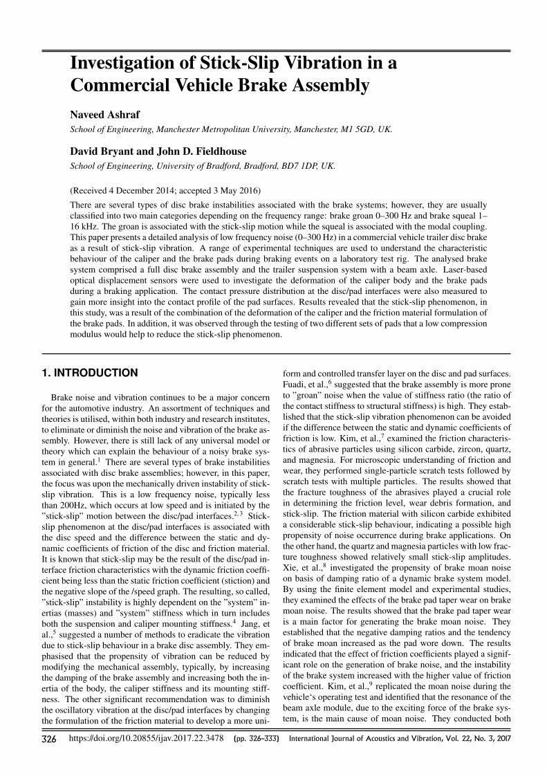
A test rig was designed and constructed to investigate thestick-slip vibration in the disc brake assembly of a commercialvehicle trailer as shown in Fig. 1. The brake assembly underconsideration was part of the trailer beam axle with air actua-tion brakes; there were two disc rotors with caliper mounted tothe beam axle on each end. A two-piston sliding-type caliperwas installed with a ventilated disc of 430 mm diameter (seeTable 1 for detailed description of brake assembly). The axlewas inverted and mounted securely to the ground by the sus-pension mechanism comprising the damper and the air spring.It was noted that this would influence the forces on the assem-bly; however, in practice it was found to have no significanteffect on noise/vibration generation. Only one disc was drivenon the test rig, so the disc rotor on the un- driven side of theaxle was securely clamped to a rigid base plate. The drivendisc was mounted on a substantial shaft held in taper rollerbearings and loaded to give zero axial float. The brake discwas driven through a flexible coupling direct from a 45 kW,2440 rpm 3-phase A.C. motor through a 30:1 worm-wheel re-ducer. Flexible coupling was used to accommodate angular,radial and parallel misalignment between the shaft, flange, andthe gearbox, thus avoiding externally induced forces being im-posed onto the brake head. Disc speed was controlled usinga ”vector” controller that provided reliable constant variablespeed starting from 1.0 rev/min up to a maximum speed of80 rev/min.
Disc temperature was measured using a non-contact laser in-frared thermometer with a range of 0 to 250◦C. A condensing-type microphone was placed at distance of 100 mm from thedisc face and 500 mm above and perpendicular to the centre-line of the disc as identified in SAE procedure J2521. FFTspectrum analyser was used to identify the generated noise fre-quencies.
Figure 1. General view of the test rig with trailer axle mounted to the floor.
Table 1. Detailed description of Brake assembly
Brake DiscDiameter (mm) 430
Effective radius (mm) 171.5Thickness (mm) 45
Brake PadsLength (mm) 210.7 (backplate)Width (mm) 84
Thickness (mm) 30 mm including 9 mm backplateSurface area (cm2) 2×148
Pad A Pad BCompressibility at 8 MPa (µm)
180 243Compressive Stiffness (GPa)
3.5 2.5Brake Caliper
Type Sliding caliper brake (pneumatic)No of pistons 2 pistons
3. EXPERIMENTAL PROCEDURE
The ”stick-slip” vibration characteristic/propensity wasrecorded by measuring noise levels and frequencies. Initiallybrake pads with high compression modulus (Pad A) were usedto examine the stick-slip phenomenon. A temperature/pressurenoise matrix test was conducted to determine the noise propen-sity of the brake system during the generation of stick-slipvibrations. All brake pads were fully ”bedded in” with thebrake disc before performing any noise tests to ensure consis-tent and reliable results. The bedding-in procedure involvedperforming short drag braking events at different speeds (10–80rev/min) and pressures (between 1–5 bar air actuation pres-sure) whilst allowing the brake disc temperature to steadily in-crease to 250◦C. Temperature rise during each braking eventwas in the region of 10–20◦C and the disc temperature at thebeginning of the ”bedding” procedure was 20◦C. Once thedisc temperature of 250◦C had been reached, the disc was al-lowed to cool down to 20◦C. Following this process, the brakewas examined visually and the disc and pad surfaces were in-spected to ensure that full contact between disc and pad hadbeen achieved (a clean and uniform rubbing path) and, by ob-servation, that the surface transfer was complete about the disc.
For the experimental measurements, the temperature of thedisc was raised, through braking applications, to over 250◦C
International Journal of Acoustics and Vibration, Vol. 22, No. 3, 2017 327
N. Ashraf, et al.: INVESTIGATION OF STICK-SLIP VIBRATION IN A COMMERCIAL VEHICLE BRAKE ASSEMBLY
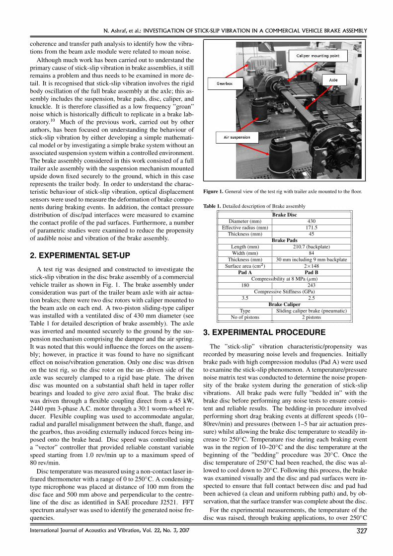
Figure 2. Frequency spectrum of the recorded noise using microphone (PadA).
Table 2. Test criteria and brake noise characteristics.
Applied Disc Speed Temperature Frequency Type ofPressure (rev/min) (◦C) (Hz) Noise
(bar)2.5 14 150 180 Stick-slip
and the brake speed was set at 14 rev/min. As the disc temper-ature decayed due to cooling the brake pressure gradually in-creased and decreased; any noticeable noise frequencies wererecorded together with the disc temperature and the brake linepressure. The test characteristics that generated the low fre-quency noise are shown in Table 2 and Fig. 2.
4. RESULTS
Preliminary noise tests revealed that whenever stick-slipnoise occurred, the inboard pad showed a trailing series ofsuccessive pad imprints (”chatter” marks) on the surface of thedisc, which was indicative of the stick-slip phenomenon. How-ever there was no evidence of pad imprints on the outboardsurface of the disc; this unusual behaviour of the inboard padmay have been responsible for the instability within the brakeassembly. It was also evident from noise assessment tests thatthe part-worn pads tended to generate stick-slip noise more of-ten than freshly bedded pads.
Laser-based optical displacement sensors manufactured byMicro-Epsilon (model no: ILD1300-20) were used to inves-tigate the deformation of the brake components including thecaliper and the pads during braking events. The measuringrange of these sensors is between 20–200 mm with the dy-namic resolution of 100 µm, a measuring rate of 750 Hzand the operating temperature range is between 0–50◦C. ALabview-based programme with integrated data acquisitionwas developed to measure the displacement of brake compo-nents during testing.
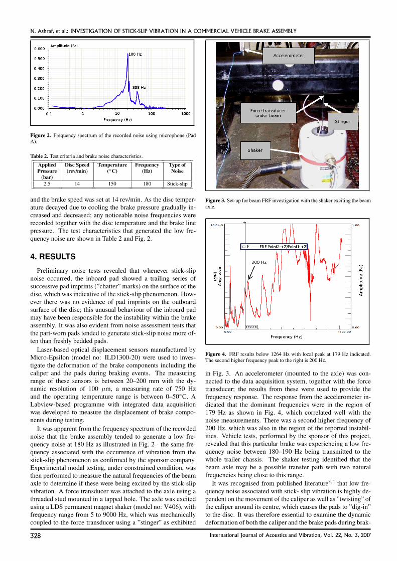
It was apparent from the frequency spectrum of the recordednoise that the brake assembly tended to generate a low fre-quency noise at 180 Hz as illustrated in Fig. 2 - the same fre-quency associated with the occurrence of vibration from thestick-slip phenomenon as confirmed by the sponsor company.Experimental modal testing, under constrained condition, wasthen performed to measure the natural frequencies of the beamaxle to determine if these were being excited by the stick-slipvibration. A force transducer was attached to the axle using athreaded stud mounted in a tapped hole. The axle was excitedusing a LDS permanent magnet shaker (model no: V406), withfrequency range from 5 to 9000 Hz, which was mechanicallycoupled to the force transducer using a ”stinger” as exhibited
Figure 3. Set-up for beam FRF investigation with the shaker exciting the beamaxle.
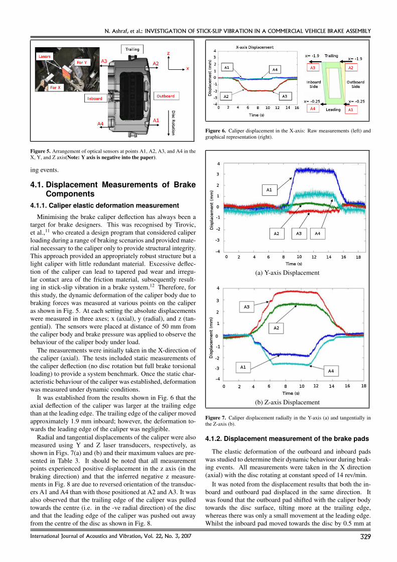
Figure 4. FRF results below 1264 Hz with local peak at 179 Hz indicated.The second higher frequency peak to the right is 200 Hz.
in Fig. 3. An accelerometer (mounted to the axle) was con-nected to the data acquisition system, together with the forcetransducer; the results from these were used to provide thefrequency response. The response from the accelerometer in-dicated that the dominant frequencies were in the region of179 Hz as shown in Fig. 4, which correlated well with thenoise measurements. There was a second higher frequency of200 Hz, which was also in the region of the reported instabil-ities. Vehicle tests, performed by the sponsor of this project,revealed that this particular brake was experiencing a low fre-quency noise between 180–190 Hz being transmitted to thewhole trailer chassis. The shaker testing identified that thebeam axle may be a possible transfer path with two naturalfrequencies being close to this range.
It was recognised from published literature3, 4 that low fre-quency noise associated with stick- slip vibration is highly de-pendent on the movement of the caliper as well as ”twisting” ofthe caliper around its centre, which causes the pads to ”dig-in”to the disc. It was therefore essential to examine the dynamicdeformation of both the caliper and the brake pads during brak-
328 International Journal of Acoustics and Vibration, Vol. 22, No. 3, 2017
N. Ashraf, et al.: INVESTIGATION OF STICK-SLIP VIBRATION IN A COMMERCIAL VEHICLE BRAKE ASSEMBLY
Figure 5. Arrangement of optical sensors at points A1, A2, A3, and A4 in theX, Y, and Z axis(Note: Y axis is negative into the paper).
ing events.
4.1. Displacement Measurements of BrakeComponents
4.1.1. Caliper elastic deformation measurement
Minimising the brake caliper deflection has always been atarget for brake designers. This was recognised by Tirovic,et al.,11 who created a design program that considered caliperloading during a range of braking scenarios and provided mate-rial necessary to the caliper only to provide structural integrity.This approach provided an appropriately robust structure but alight caliper with little redundant material. Excessive deflec-tion of the caliper can lead to tapered pad wear and irregu-lar contact area of the friction material, subsequently result-ing in stick-slip vibration in a brake system.12 Therefore, forthis study, the dynamic deformation of the caliper body due tobraking forces was measured at various points on the caliperas shown in Fig. 5. At each setting the absolute displacementswere measured in three axes; x (axial), y (radial), and z (tan-gential). The sensors were placed at distance of 50 mm fromthe caliper body and brake pressure was applied to observe thebehaviour of the caliper body under load.
The measurements were initially taken in the X-direction ofthe caliper (axial). The tests included static measurements ofthe caliper deflection (no disc rotation but full brake torsionalloading) to provide a system benchmark. Once the static char-acteristic behaviour of the caliper was established, deformationwas measured under dynamic conditions.
It was established from the results shown in Fig. 6 that theaxial deflection of the caliper was larger at the trailing edgethan at the leading edge. The trailing edge of the caliper movedapproximately 1.9 mm inboard; however, the deformation to-wards the leading edge of the caliper was negligible.
Radial and tangential displacements of the caliper were alsomeasured using Y and Z laser transducers, respectively, asshown in Figs. 7(a) and (b) and their maximum values are pre-sented in Table 3. It should be noted that all measurementpoints experienced positive displacement in the z axis (in thebraking direction) and that the inferred negative z measure-ments in Fig. 8 are due to reversed orientation of the transduc-ers A1 and A4 than with those positioned at A2 and A3. It wasalso observed that the trailing edge of the caliper was pulledtowards the centre (i.e. in the -ve radial direction) of the discand that the leading edge of the caliper was pushed out awayfrom the centre of the disc as shown in Fig. 8.
Figure 6. Caliper displacement in the X-axis: Raw measurements (left) andgraphical representation (right).
(a) Y-axis Displacement
(b) Z-axis Displacement
Figure 7. Caliper displacement radially in the Y-axis (a) and tangentially inthe Z-axis (b).
4.1.2. Displacement measurement of the brake pads
The elastic deformation of the outboard and inboard padswas studied to determine their dynamic behaviour during brak-ing events. All measurements were taken in the X direction(axial) with the disc rotating at constant speed of 14 rev/min.
It was noted from the displacement results that both the in-board and outboard pad displaced in the same direction. Itwas found that the outboard pad shifted with the caliper bodytowards the disc surface, tilting more at the trailing edge,whereas there was only a small movement at the leading edge.Whilst the inboard pad moved towards the disc by 0.5 mm at
International Journal of Acoustics and Vibration, Vol. 22, No. 3, 2017 329
N. Ashraf, et al.: INVESTIGATION OF STICK-SLIP VIBRATION IN A COMMERCIAL VEHICLE BRAKE ASSEMBLY
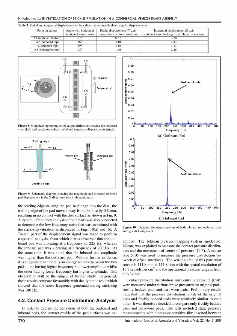
Table 3. Radial and tangential displacement of the caliper including calculated angular displacements.
Point on caliper Angle with horizontal Radial displacement (Y axis Tangential displacement (Z axis(anticlockwise = +ve) - away from centre = +ve) mm - anticlockwise, looking from inboard = +ve) mm
A1 (outboard bottom) -18◦ 0.57 3.70A2 (outboard top) 58◦ -1.01 2.43A3 (inboard top) 69◦ -1.66 3.33
A4 (inboard bottom) -29◦ 1.60 2.26
Figure 8. Graphical representation of caliper deflection showing the outboardview (left) and maximum caliper radial and tangential displacements (right).
Figure 9. Schematic diagram showing the magnitude and direction of brakepad displacement in the X-direction (axial) - dynamic tests.
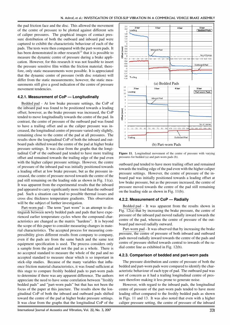
the leading edge causing the pad to plunge into the disc, thetrailing edge of the pad moved away from the disc by 0.8 mm,resulting in no contact with the disc surface as shown in Fig. 9.A dynamic frequency analysis of both pads was also conductedto determine the low frequency noise that was associated withthe stick-slip vibration as displayed in Figs. 10(a) and (b). A”burst” part of the displacement signal was taken to performa spectral analysis, from which it was observed that the out-board pad was vibrating at a frequency of 225 Hz, whereasthe inboard pad was vibrating at a frequency of 200 Hz. Atthe same time, it was noted that the inboard pad amplitudewas higher than the outboard pad. Without further evidence,it is suggested that there is an energy balance between the twopads - one having higher frequency but lower amplitude whilstthe other having lower frequency but higher amplitude. Thisobservation will be the subject of further study. In general,these results compare favourably with the dynamic tests whichshowed that the noise frequency generated during stick-slipwas 180 Hz.
4.2. Contact Pressure Distribution AnalysisIn order to explain the behaviour of both the outboard and
inboard pads, the contact profile of the pad surfaces was ex-
(a) Outboard Pad
(b) Inboard Pad
Figure 10. Dynamic frequency analysis of both inboard and outboard padsduring a stick-slip event.
amined. The Tekscan pressure mapping system (model no:I-Scan) was exploited to measure the contact pressure distribu-tion and the movement of centre of pressure (CoP). A sensortype 5105 was used to measure the pressure distribution be-tween disc/pad interfaces. The sensing area of this particularsensor is 111.8 mm × 111.8 mm with the spatial resolution of15.7 sensels per cm2 and the operational pressure range is from0 to 34 bar.
Contact pressure distribution and centre of pressure (CoP)were measured under various brake pressures for original pads,freshly bedded pads and part-worn pads. Preliminary resultsindicated that the pressure distribution profile of the originalpads and freshly bedded pads were relatively similar to eachother. It was therefore decided to compare only freshly beddedpads and part-worn pads. The tests included static pressuremeasurements with a pressure sensitive film inserted between
330 International Journal of Acoustics and Vibration, Vol. 22, No. 3, 2017
N. Ashraf, et al.: INVESTIGATION OF STICK-SLIP VIBRATION IN A COMMERCIAL VEHICLE BRAKE ASSEMBLY
the pad friction face and the disc. This allowed the movementof the centre of pressure to be plotted against different setsof caliper pressures. The graphical images of contact pres-sure distribution of both the outboard and inboard pad werecaptured to exhibit the characteristic behaviour of each of thepads. The tests were then compared with the part-worn pads. Ithas been demonstrated in other research13 that it is possible tomeasure the dynamic centre of pressure during a brake appli-cation. However, for this research it was not feasible to insertthe pressure sensitive film within the friction material; there-fore, only static measurements were possible. It is appreciatedthat the dynamic centre of pressure (with disc rotation) willdiffer from the static measurements; however, the static mea-surements still give a good indication of the centre of pressuremovement tendencies.
4.2.1. Measurement of CoP — Longitudinally
Bedded pad - At low brake pressure settings, the CoP ofthe inboard pad was found to be positioned towards a leadingoffset; however, as the brake pressure was increased, the CoPtended to move longitudinally towards the centre of the pad. Incontrast, the centre of pressure of the outboard pad was foundto have a trailing offset and as the caliper pressure was in-creased, the longitudinal centre of pressure varied only slightly,remaining close to the centre of the pad at all pressures. Theresults show the longitudinal CoP of both the inboard and out-board pads shifted toward the centre of the pad at higher brakepressure settings. It was clear from the graphs that the longi-tudinal CoP of the outboard pad tended to have more trailingoffset and remained towards the trailing edge of the pad evenwith the higher caliper pressure settings. However, the centreof pressure of the inboard pad was initially positioned towardsa leading offset at low brake pressure, but as the pressure in-creased, the centre of pressure moved towards the centre of thepad still remaining on the leading side as shown in Fig. 11(a).It was apparent from the experimental results that the inboardpad appeared to carry significantly more load than the outboardpad. Such a situation can lead to possible thermal issues andcross disc thickness temperature gradients. This observationwill be the subject of further investigation.
Part-worn pad - The term ”part worn” is an attempt to dis-tinguish between newly bedded pads and pads that have expe-rienced earlier temperature cycles where the compound char-acteristics are changed as the matrix ”hardens”. It is beyondthe scope of this paper to consider measuring changes in mate-rial characteristics. The accepted process for measuring com-pressibility gives different results from company to company,even if the pads are from the same batch and the same testequipment specification is used. The process considers onlya sample from the pad and not the pad as a whole. There isno accepted standard to measure the whole of the pad and noaccepted standard to measure shear which is so important instick-slip studies. Because of the many variables that influ-ence friction material characteristics, it was found sufficient atthis stage to compare freshly bedded pads to part-worn padsto determine if there was any apparent difference. The authorsappreciate the need to have some correlation between ”freshlybedded pads” and ”part-worn pads” but that has not been thefocus of the paper at this juncture. The results show the lon-gitudinal CoP of both the inboard and outboard pads shiftedtoward the centre of the pad at higher brake pressure settings.It was clear from the graphs that the longitudinal CoP of the
(a) Bedded Pads
(b) Part-worn Pads
Figure 11. Longitudinal movement of the centre of pressure with varyingpressures for bedded (a) and part-worn pads (b).
outboard pad tended to have more trailing offset and remainedtowards the trailing edge of the pad even with the higher caliperpressure settings. However, the centre of pressure of the in-board pad was initially positioned towards a leading offset atlow brake pressure, but as the pressure increased, the centre ofpressure moved towards the centre of the pad still remainingon the leading side as shown in Fig. 11(b).
4.2.2. Measurement of CoP — Radially
Bedded pad - It was apparent from the results shown inFig. 12(a) that by increasing the brake pressure, the centre ofpressure of the inboard pad moved radially inward towards thecentre of the pad, whereas the centre of pressure of the out-board pad moved radially outward.
Part-worn pad - It was observed that by increasing the brakepressure, the centre of pressure of both inboard and outboardpads moved radially inward towards the centre of the pads andcentre of pressure shifted towards central to inwards of the ra-dial centre line as exhibited in Fig. 12(b).
4.2.3. Comparison of bedded and part-worn pads
The pressure distribution and centre of pressure of both thebedded and part-worn pads were compared to identify the char-acteristic behaviour of each type of pad. The outboard pad wasnot of concern as it had a trailing longitudinal centre of pres-sure therefore making it less prone to generate noise.
However, with regard to the inboard pads, the longitudinalcentre of pressure of the part-worn pads tended to have moreleading offset compared to the freshly bedded pads as shownin Figs. 11 and 13. It was also noted that even with a highercaliper pressure setting, the centre of pressure of the inboard
International Journal of Acoustics and Vibration, Vol. 22, No. 3, 2017 331

N. Ashraf, et al.: INVESTIGATION OF STICK-SLIP VIBRATION IN A COMMERCIAL VEHICLE BRAKE ASSEMBLY
(a) Bedded Pads
(b) Part-worn Pads
Figure 12. Radial movement of the centre of pressure for bedded (a) andpart-worn pads (b).
Figure 13. Movement of CoP with various hydraulic pressures on the actualpad surface (inboard pad).
pad remained towards the leading edge resulting in higher con-tact area at the leading edge as shown in Fig. 13; this was po-tentially a cause of instability in the assembly.
4.3. Effects of Different Parameters on Stick-Slip Vibration
It was established from the above results that large deforma-tions of the caliper and non-uniform contact between the padsand disc were occurring. It was believed that both of thesecould be causing, or influencing, the stick-slip motion. As de-scribed in Section 1, the tangential stiffness of the brake assem-bly (typically pads, caliper and anchor bracket) can influencethe stick-slip vibration when the sliding velocity is within thecritical region where the friction-velocity graph has a negativeslope. Therefore, by influencing the stiffness of either the padsor caliper assembly a change may result.
(a) Pad A
(b) Pad B
Figure 14. Comparison of two sets of pads with different friction materials.
4.3.1. Effect of different friction material
Brake pads with different friction materials, which had dif-ferent compressive stiffnesses, were fitted to observe their ef-fect on the propensity for brake noise. It was established fromnoise assessment tests as displayed in Figs. 14(a) and (b), thatthe brake pad with the lower stiffness friction material (Pad B)reduced the occurrence of stick-slip vibration and was there-fore less prone to the associated noise as shown in Fig. 14(b).Compressive stiffness of the pads should be as low as possibleto promote uniform contact pressure but at the same time highenough to achieve a ”good pedal feel” and an optimal brakeperformance in terms of brake torque capability. This will besubject to further investigation.
4.4. Discussion of ResultsIt was found that the low frequency stick-slip vibration and
resultant noise depended on the elastic deformation of thecaliper and the friction material of the pad. It was establishedthat the trailing edge of the caliper deformed significantly inthe axial direction whereas leading end deformation was al-most negligible. This unusual deformation behaviour of thecaliper allowed the contact pressure distribution between thedisc/pad interfaces to change considerably causing the stick-
332 International Journal of Acoustics and Vibration, Vol. 22, No. 3, 2017

N. Ashraf, et al.: INVESTIGATION OF STICK-SLIP VIBRATION IN A COMMERCIAL VEHICLE BRAKE ASSEMBLY
slip phenomenon — the pads were incapable of maintaining agrip on the disc. A large deflection at the trailing edge of thecaliper caused the outboard pad to distort with the caliper in thesame direction, however, causing the inboard pad to compressmore against the disc towards the leading edge resulting in lossof contact with the disc towards the trailing edge of the pad. Itwas observed that the inboard pad vibrated more vigorouslybecause of the dissimilar contact area towards the leading andtrailing edges of the pad. A similar result was also obtainedduring the noise frequency tests.
The pressure distribution results also corroborated that thecentre of pressure of the inboard pad was moving more dy-namically, causing instability in the brake system. The discbrake was more prone to noise when the centre of pressurewas towards the leading edge of the pad. In order to reduce theintensity of noise within the brake system, the position of thecentre of pressure must be towards the trailing edge of the pad.It was observed that noise would be more likely if the centre ofpressure moved radially inwards towards the centre of the pad.These findings compared well with the previous work by Field-house, et al.,13 in which it was reported that the ideal positionfor the centre of pressure of the pad would be central to trailing,and radially out from the pad centreline. It was observed thatin order to ensure consistent disc brake performance, the inter-face distribution should be cautiously controlled to maintain auniform pressure distribution along the length of the pad.
It was also observed that part-worn pads tended to gener-ate stick-slip vibration more often compared to freshly beddedpads. This could be due to the fact that the part-worn pad fric-tion material changes during use, thus increasing the elasticcompression stiffness of the pads leading to a reduced contactarea towards the leading edge.
5. CONCLUSIONS
It has been shown that stick-slip vibration depends to a sig-nificant extent on the deformation of the caliper, especially to-wards the leading edge, causing instability in a commercial ve-hicle brake assembly, and that the caliper mounting and struc-tural geometry should be designed to withstand the stressesgenerated during dynamic braking. It can also be concludedthat uneven contact area of the brake pad can prompt stick-slip vibration, the contact area being reduced as the caliper de-forms. In order to suppress the stick-slip vibration in a discbrake, the friction material should have a lower compressivestiffness, thus providing more uniform contact between thedisc/pad interfaces and maintaining a greater contact area. It islikely that the compression modulus required to prevent stick-slip will differ depending upon the type and construction ofthe brake assembly; however, a study of the effect on differ-ent assemblies would provide further useful information. Al-though it has not been addressed in this study, it is necessaryto consider the shear characteristics of the friction compoundin future studies.
REFERENCES1 Akay, A. Acoustics of friction, Journal of the Acous-
tical Society of America, 111 (4), 1525–1548, (2002).https://dx.doi.org/10.1121/1.1456514
2 Abdelhamid, M. K. Creep Groan of DiscBrakes, SAE technical paper 951282, (1995).https://dx.doi.org/10.4271/951282
3 Brecht, J., Hoffrichter, W., and Dohle, and A. Mechanismsof brake creep-groan, SAE technical paper 973026, (1997).https://dx.doi.org/10.4271/973026
4 Crowther, A. R. and Singh, R. Identification andquantification of stick-slip induced brake groanevents using experimental and analytical investiga-tions, Noise Control Eng. J., 56 (4), 235–255, (2008).https://dx.doi.org/10.3397/1.2955772
5 Jang, H., Lee, J. S., and Fash, J. W. Composi-tional effects of the brake friction material on creepgroan phenomena, Wear, 251 (1-12), 1477–1483, (2001).https://dx.doi.org/10.1016/s0043-1648(01)00786-4
6 Fuadi, Z., Maegawa, S., Nakano, K., and Adachi, K. Mapof low-frequency stick- slip of a creep groan, Proc. IMechEPart J: J. Engineering Tribology, 224 (12), 1235–1246,(2010). https://dx.doi.org/10.1243/13506501jet834
7 Kim, S. S., Hwang, H. J., Shin, M. W., and Jang, H. Frictionand vibration of automotive brake pads containing differ-ent abrasive particles, Wear, 271 (7-8), 1194– 1202, (2011).https://dx.doi.org/10.1016/j.wear.2011.05.037
8 Xie, M. S., Zhang, G. R., Li, J. H. and Fritsch, R. Brakepad taper wear on brake moan noise, International Jour-nal of Automotive Technology, 15 (4), 565–571, (2014).https://dx.doi.org/10.1007/s12239-014-0059-x
9 Kim, Y. -D., Jeong, U. -C., Kim, J. -S., Seo, J. -H., Park, T.-S., Lee, S. -H., Yoon, J. -M., and Oh, J. -E. Reductionin the moan noise by frequency-response-function-basedsubstructuring and optimization techniques, Proc IMechEPart D: J Automobile Engineering, 229 (11), 1443–1456,(2015). https://dx.doi.org/10.1177/0954407014564690
10 Bettella, M., Harrison, M. F., and Sharp, R. S. In-vestigation of automotive creep groan noise witha distributed-source excitation technique, Journalof Sound & Vibration, 255 (3), 531–547, (2002).https://dx.doi.org/10.1006/jsvi.2001.4178
11 Tirovic, M. and Day, A. J. Disc brake interfacepressure distributions, Proc IMechE Part D: J Au-tomobile Engineering, 205 (24), 137–146, (1991).https://dx.doi.org/10.1243/pime proc 1991 205 162 02
12 Kim, J., Lee, C., and Kim, S. Investigation on correlationbetween groan noise and coefficient of friction with frictionmaterial’s difference, SAE technical paper 2004-01-0827,(2004). https://dx.doi.org/10.4271/2004-01-0827
13 Fieldhouse, J., Ashraf, N., Talbot, C., and Pasquet, T.Measurement of the dynamic centre of pressure of thedisc/pad interface during a braking operation, Interna-tional Journal of Vehicle Design, 51 (1/2), 73–104, (2009).https://dx.doi.org/10.1504/ijvd.2009.027116
International Journal of Acoustics and Vibration, Vol. 22, No. 3, 2017 333


