Embed Size (px)
Citation preview
HAL Id: hal-02024999https://hal.archives-ouvertes.fr/hal-02024999
Submitted on 19 Feb 2019
HAL is a multi-disciplinary open accessarchive for the deposit and dissemination of sci-entific research documents, whether they are pub-lished or not. The documents may come fromteaching and research institutions in France orabroad, or from public or private research centers.
L’archive ouverte pluridisciplinaire HAL, estdestinée au dépôt et à la diffusion de documentsscientifiques de niveau recherche, publiés ou non,émanant des établissements d’enseignement et derecherche français ou étrangers, des laboratoirespublics ou privés.
Investigation of circular polarization for 76 GHzhelicopter collision avoidance radar to improve detection
performance of high-voltage power linesShunichi Futatsumori, Capucine Amielh, Kazuyuki Morioka, Akiko Kohmura,
Norihiko Miyazaki, Naruto Yonemoto
To cite this version:Shunichi Futatsumori, Capucine Amielh, Kazuyuki Morioka, Akiko Kohmura, Norihiko Miyazaki, etal.. Investigation of circular polarization for 76 GHz helicopter collision avoidance radar to improvedetection performance of high-voltage power lines. EURAD 2017, 14th European Microwave Confer-ence„ Oct 2017, Nuremberg, Germany. pp.Pages 295-298/ ISBN : 978-287487049-1, �10.23919/EU-RAD.2017.8249205�. �hal-02024999�
Investigation on Circular Polarization for 76 GHz Helicopter Collision Avoidance Radar to Improve
Detection Performance of High-Voltage Power Lines Shunichi Futatsumori#1, Capucine Amielh*, Kazuyuki Morioka#, Akiko Kohmura#, Norihiko Miyazaki#, Naruto
Yonemoto# #Surveillance and Communications Department, Electronic Navigation Research Institute
National Institute of Maritime, Port and Aviation Technology, 7-42-23, Jindaiji-higashi, Chofu, Tokyo, 182-0012 Japan [email protected]
*Ecole Nationale de l’Aviation Civile Toulouse, France
Abstract— To improve the detection conditions of the high-voltage power lines using the 76 GHz low-transmitting power helicopter collision avoidance forward looking millimeter-wave radar, the characteristics of the circular polarization is experimentally investigated. Firstly, the specifications and the operating parameters of developed circular polarized 76 GHz is discussed. Then, the radar receiving module with the W-band low noise amplifier and the low loss waveguide to microstrip line transitions enables 12 dB receiving noise figure. Finally, the ground power line detection test is carried out to compare the circular polarization and vertical polarization, which are commonly used to detect the power lines. The results confirm the almost 10 dB increase of the reflection signal of the power lines.
I. INTRODUCTION
As the helicopters are operated at low altitude with visual flights, there are some risks to collide with the terrestrial objects even in the fair conditions [1], [2]. The some accidents reports describe that they are collide with the high-voltage power lines or the surrounding objects. To support the pilots, some detection and warning system have been discussed so far [3], [4]. We have been developed collision avoidance forward looking low-transmitting power 76 GHz millimeter-wave radar [5], [6]. This is because the millimeter-wave radar enables a high-range resolution, a small volume, and weather robustness. In addition, as the millimeter-wave radars for the automotive applications have been received attention in recent years, the high-performance devices for the E-band or the W-band are commercially available with reasonable costs.
In this paper, the investigation on the circular polarization for the 76 GHz millimeter-wave helicopter collision radar is discussed. The purpose of employing the circular polarization is to improve the detection performance of the high-voltage power lines. We have been developed the millimeter-wave with linear polarized antenna [5], however, it is confirmed from the power line radar cross section (RCS) measurement that the circular polarization is effective to detect the power lines [7]. Firstly, the newly developed circular polarized 76 GHz millimeter-wave radar is discussed with the specifi-cations. Then, the characteristics the fabricated receiver front-end module are discussed based on the measurement results.
-20 -10 0 10 20-40
-30
-20
-10
0
Azimuth angle (degree)
RC
S (
dBm
2 )
Vertical-Vertical polarization Horizontal-Horizontal polarization
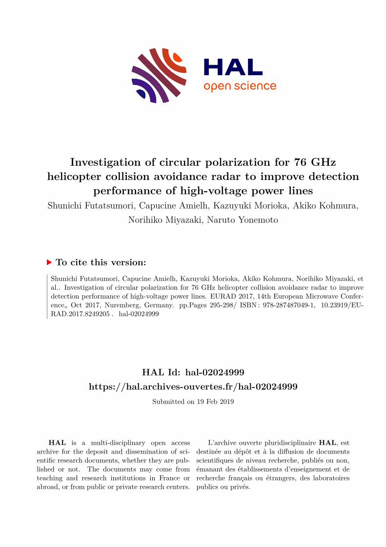
Fig. 1. Example of the measured RCS characteristics of the high-voltage power lines at 76 GHz band. (Polarization: vertical for both transmission and reception, horizontal for both transmission and reception)
Finally, the results of the ground detection test of the high-voltage power lines, which aims to evaluate the circular polarized millimeter-wave radar, are discussed for the future fight experiments.
II. CIRCULAR POLARIZED 76 GHZ LOW POWER RADAR
The polarization characteristic of the high-voltage power line RCS at 76 GHz band have been evaluated based on the experiments [7]. To detect the power lines by the millimeter-wave radar, the vertical polarization is commonly employed to detect the power lines. This is because the outer strands of the power lines are almost perpendicular to the vertical polarized incident waves. These polarization characteristics are suitable to obtain the Bragg scattering from the periodic structure of the outer strands. From the measurement results, however, it is confirmed that the specular reflection with the horizontal polarization is also useful to detect the power lines. Fig. 1 shows the measured RCS characteristics of the typical high-voltage power lines [7]. The several reflection peaks are observed between -20 degrees and 20 degrees. In addition, the specular reflection with the horizontal polarization at the facing position is larger than 10 dB. The detection conditions
CFRP parabolicreflector
Pitch active stabilizer
76 GHz millimeter-wave radar
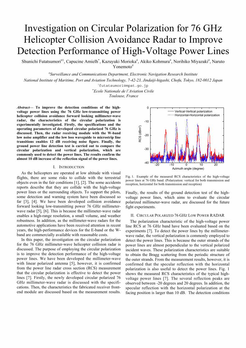
Signal processing unit Fig. 2. Overview of the developed circular polarized 76 GHz low transmitting power millimeter-wave radar for helicopter obstacle detection.
TABLE I. SPECIFICATION OF CIRCULAR POLARIZED 76 GHZ MILLIMITER-WAVE LOW POWER RADAR
Center frequency 76.5 GHz
Bandwidth Up to 1 GHz
Output power 10 dBm
Antenna gain 35.6 dBic
Ranging method FMCW
Frequency modulation method Sawtooth
FM chirp length 2.048 ms
Receiver noise figure 12 dB
Transmitter and receiver isolation 35 dB
of the high-voltage power lines using the 76 GHz band millimeter-wave radar can be improved by utilizing the both polarizations. This is one of the motivations to develop the circular polarized millimeter-wave radar. Fig. 2 shows the overview of the developed circular polarized 76 GHz low- transmitting power millimeter-wave radar for helicopter obstacle detection. The antenna is a carbon fiber reinforced plastic (CFRP) parabolic reflector antenna with the azimuth mechanical scanning. The pitch active stabilizer is installed for the movement of the helicopter. In addition, Table I show the specifications of the developed radar system. These characteristics are designed to satisfy the specified low power radar regulation in Japan [8], which does not require the radio license.
To develop the circular polarized millimeter-wave radar system, the stepped septum polarizer is employed. The measured isolation and is axial ration is about 35 dB and 1.1 dB, respectively. As a result, the antenna gain of the circular polarized primary source with CFRP reflector is 35.6 dBic. Then, the previously developed radar system employs the direct-conversion detection method to obtain the receiving beat signal [00]. The advantage of this method is the simple and the low-cost circuit construction. On the other hand, the RF low-noise amplifier (LNA) is difficult to utilize because the isolation of the receiving and the transmitting signals are generally low value due to the direct signal mixing. This lead to increase the receiving noise figure (NF) and the RF-IF conversion loss. Fig. 3 and Fig. 4 show the block diagram and the overview of the receiving 76 GHz millimeter-wave radar
UMS CHU3377
WG-MSL P.A.
RF input
Local input
IF output(Baseband)
Receiver front-end module
FMCW source
UMSCHA1077A
LNA x 6
UMSCHM2179
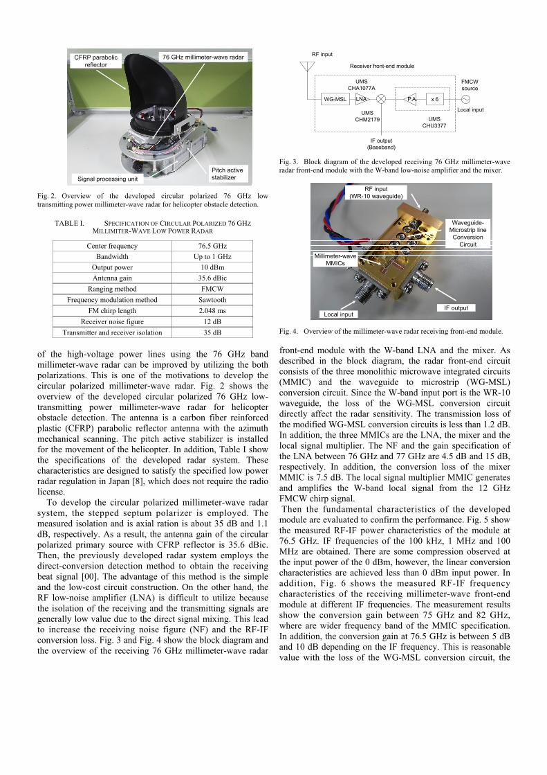
Fig. 3. Block diagram of the developed receiving 76 GHz millimeter-wave radar front-end module with the W-band low-noise amplifier and the mixer.
Waveguide-Microstrip line
ConversionCircuit
RF input(WR-10 waveguide)
IF outputLocal input
Millimeter-waveMMICs
Fig. 4. Overview of the millimeter-wave radar receiving front-end module.
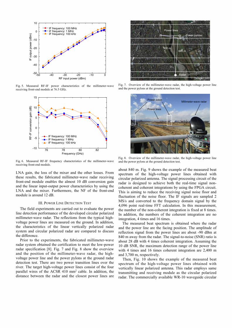
front-end module with the W-band LNA and the mixer. As described in the block diagram, the radar front-end circuit consists of the three monolithic microwave integrated circuits (MMIC) and the waveguide to microstrip (WG-MSL) conversion circuit. Since the W-band input port is the WR-10 waveguide, the loss of the WG-MSL conversion circuit directly affect the radar sensitivity. The transmission loss of the modified WG-MSL conversion circuits is less than 1.2 dB. In addition, the three MMICs are the LNA, the mixer and the local signal multiplier. The NF and the gain specification of the LNA between 76 GHz and 77 GHz are 4.5 dB and 15 dB, respectively. In addition, the conversion loss of the mixer MMIC is 7.5 dB. The local signal multiplier MMIC generates and amplifies the W-band local signal from the 12 GHz FMCW chirp signal. Then the fundamental characteristics of the developed module are evaluated to confirm the performance. Fig. 5 show the measured RF-IF power characteristics of the module at 76.5 GHz. IF frequencies of the 100 kHz, 1 MHz and 100 MHz are obtained. There are some compression observed at the input power of the 0 dBm, however, the linear conversion characteristics are achieved less than 0 dBm input power. In addition, Fig. 6 shows the measured RF-IF frequency characteristics of the receiving millimeter-wave front-end module at different IF frequencies. The measurement results show the conversion gain between 75 GHz and 82 GHz, where are wider frequency band of the MMIC specification. In addition, the conversion gain at 76.5 GHz is between 5 dB and 10 dB depending on the IF frequency. This is reasonable value with the loss of the WG-MSL conversion circuit, the
-50 -40 -30 -20 -10 0-50
-40
-30
-20
-10
0
10
RF input power (dBm)
IF o
utpu
t pow
er (
dBm
)IF frequency: 100 MHzIF frequency: 1 MHzIF frequency: 100 kHz
Fig. 5. Measured RF-IF power characteristics of the millimeter-wave receiving front-end module at 76.5 GHz.
76 78 80 82-10
-5
0
5
10
15
Frequency (GHz)
RF
-IF
con
vers
ion
gain
(dB
)
IF frequency: 100 MHzIF frequency: 1 MHzIF frequency: 100 kHz
Fig. 6. Measured RF-IF frequency characteristics of the millimeter-wave receiving front-end module.
LNA gain, the loss of the mixer and the other losses. From these results, the fabricated millimeter-wave radar receiving front-end module enables the almost 10 dB conversion gain and the linear input-output power characteristics by using the LNA and the mixer. Furthermore, the NF of the front-end module is around 12 dB.
III. POWER LINE DETECTION TEST
The field experiments are carried out to evaluate the power line detection performance of the developed circular polarized millimeter-wave radar. The reflections from the typical high-voltage power lines are measured on the ground. In addition, the characteristics of the linear vertically polarized radar system and circular polarized radar are compared to discuss the difference.
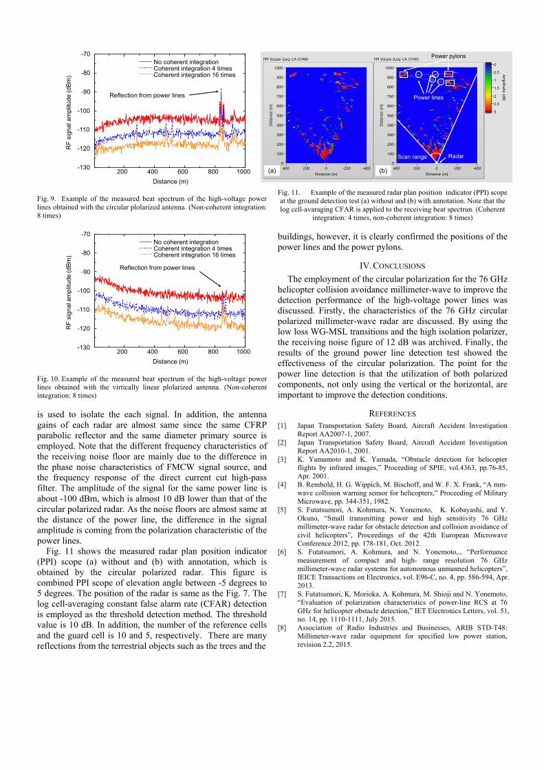
Prior to the experiments, the fabricated millimeter-wave radar system obtained the certification to meet the low-power radar specification [8]. Fig. 7 and Fig. 8 show the overview and the position of the millimeter-wave radar, the high-voltage power line and the power pylons at the ground radar detection test. There are two power transition lines over the river. The target high-voltage power lines consist of the four parallel wires of the ACSR 410 mm2 cable. In addition, the distance between the radar and the closest power lines are
Radar
840 m
Power pylons
Power lines
900 m
Fig. 7. Overview of the millimeter-wave radar, the high-voltage power line and the power pylons at the ground detection test.
Millimeter-wave radarPower pylon
Power lines
Fig. 8. Overview of the millimeter-wave radar, the high-voltage power line and the power pylons at the ground detection test.
about 840 m. Fig. 9 shows the example of the measured beat spectrum of the high-voltage power lines obtained with circular polarized antenna. The signal processing circuit of the radar is designed to achieve both the real-time signal non-coherent and coherent integrations by using the FPGA circuit. This is aiming to reduce the receiving signal noise floor and fluctuation of the noise floor. The IF signals are sampled 2 MS/s and converted to the frequency domain signal by the 4,096 point real-time FFT calculation. In this measurement, the number of the non-coherent integration is fixed at 8 times. In addition, the numbers of the coherent integration are no integration, 4 times and 16 times.
The measured beat spectrum is obtained where the radar and the power line are the facing position. The amplitude of reflection signal from the power lines are about -90 dBm at 840 m away from the radar. The signal-to-noise (SNR) ratio is about 28 dB with 4 times coherent integration. Assuming the 10 dB SNR, the maximum detection range of the power line with 4 times and 16 times coherent integration are 2,400 m and 3,700 m, respectively.
Then, Fig. 10 shows the example of the measured beat spectrum of the high-voltage power lines obtained with vertically linear polarized antenna. This radar employs same transmitting and receiving module as the circular polarized radar. The commercially available WR-10 waveguide circular
-130
-120
-110
-100
-90
-80
-70
RF
sig
na
lam
plitu
de(d
Bm
)
Distance (m)
200 400 600 800 1000
No coherent integration Coherent integration 4 times Coherent integration 16 times
Reflection from power lines
Fig. 9. Example of the measured beat spectrum of the high-voltage power lines obtained with the circular plolarized antenna. (Non-coherent integration: 8 times)
-130
-120
-110
-100
-90
-80
-70No coherent integration Coherent integration 4 times Coherent integration 16 times
RF
sig
na
lam
plitu
de(d
Bm
)
Distance (m)
200 400 600 800 1000
Reflection from power lines
Fig. 10. Example of the measured beat spectrum of the high-voltage power lines obtained with the virtically linear plolarized antenna. (Non-coherent integration: 8 times)
is used to isolate the each signal. In addition, the antenna gains of each radar are almost same since the same CFRP parabolic reflector and the same diameter primary source is employed. Note that the different frequency characteristics of the receiving noise floor are mainly due to the difference in the phase noise characteristics of FMCW signal source, and the frequency response of the direct current cut high-pass filter. The amplitude of the signal for the same power line is about -100 dBm, which is almost 10 dB lower than that of the circular polarized radar. As the noise floors are almost same at the distance of the power line, the difference in the signal amplitude is coming from the polarization characteristic of the power lines.
Fig. 11 shows the measured radar plan position indicator (PPI) scope (a) without and (b) with annotation, which is obtained by the circular polarized radar. This figure is combined PPI scope of elevation angle between -5 degrees to 5 degrees. The position of the radar is same as the Fig. 7. The log cell-averaging constant false alarm rate (CFAR) detection is employed as the threshold detection method. The threshold value is 10 dB. In addition, the number of the reference cells and the guard cell is 10 and 5, respectively. There are many reflections from the terrestrial objects such as the trees and the
Fig. 11. Example of the measured radar plan position indicator (PPI) scope at the ground detection test (a) without and (b) with annotation. Note that the log cell-avaraging CFAR is applied to the receiving beat spectrun. (Coherent
integration: 4 times, non-coherent integration: 8 times)
buildings, however, it is clearly confirmed the positions of the power lines and the power pylons.
IV. CONCLUSIONS
The employment of the circular polarization for the 76 GHz helicopter collision avoidance millimeter-wave to improve the detection performance of the high-voltage power lines was discussed. Firstly, the characteristics of the 76 GHz circular polarized millimeter-wave radar are discussed. By using the low loss WG-MSL transitions and the high isolation polarizer, the receiving noise figure of 12 dB was archived. Finally, the results of the ground power line detection test showed the effectiveness of the circular polarization. The point for the power line detection is that the utilization of both polarized components, not only using the vertical or the horizontal, are important to improve the detection conditions.
REFERENCES [1] Japan Transportation Safety Board, Aircraft Accident Investigation
Report AA2007-1, 2007. [2] Japan Transportation Safety Board, Aircraft Accident Investigation
Report AA2010-1, 2001. [3] K. Yamamoto and K. Yamada, “Obstacle detection for helicopter
flights by infrared images,” Proceeding of SPIE, vol.4363, pp.76-85, Apr. 2001.
[4] B. Rembold, H. G. Wippich, M. Bischoff, and W. F. X. Frank, “A mm-wave collision warning sensor for helicopters,” Proceeding of Military Microwave, pp. 344-351, 1982.
[5] S. Futatsumori, A. Kohmura, N. Yonemoto, K. Kobayashi, and Y. Okuno, “Small transmitting power and high sensitivity 76 GHz millimeter-wave radar for obstacle detection and collision avoidance of civil helicopters”, Proceedings of the 42th European Microwave Conference 2012, pp. 178-181, Oct. 2012.
[6] S. Futatsumori, A. Kohmura, and N. Yonemoto,., “Performance measurement of compact and high- range resolution 76 GHz millimeter-wave radar systems for autonomous unmanned helicopters”, IEICE Transactions on Electronics, vol. E96-C, no. 4, pp. 586-594, Apr. 2013.
[7] S. Futatsumori, K. Morioka, A. Kohmura, M. Shioji and N. Yonemoto, “Evaluation of polarization characteristics of power-line RCS at 76 GHz for helicopter obstacle detection,” IET Electronics Letters, vol. 51, no. 14, pp. 1110-1111, July 2015.
[8] Association of Radio Industries and Businesses, ARIB STD-T48: Millimeter-wave radar equipment for specified low power station, revision 2.2, 2015.
Power lines
Power pylons
(a) (b)
RadarScan range


![TR 103 137 - V1.1.1 - Electromagnetic compatibility and ... · The 76 GHz RTTT Standard EN 301 091 [i.5] and the 77 GHz to 81 GHz RTTT Standard EN 302 264 [i.8], could be used as](https://img.dokumen.tips/doc/110x75/5e0c1995a66c914f4a5d9a87/tr-103-137-v111-electromagnetic-compatibility-and-the-76-ghz-rttt-standard.jpg)