Embed Size (px)
Citation preview
1
Introduction to the Combined Finite-
Discrete Element Method Máté Hazay
Budapest University of Technology and Economics, Hungary
Ante Munjiza
Queen Mary University of London, England
ABSTRACT
This chapter presents a general overview of the combined finite-discrete element method (FEM/DEM)
which is considered as a state-of-the-art technique for the mechanical analysis of masonry structures.
In a FEM/DEM simulation each discrete element representing a stone block is discretised into finite
elements in order to describe the deformability of the blocks. This chapter deals with the main steps of
the FEM/DEM including contact detection, contact interaction, fracture and fragmentation
algorithms, calculation of deformations and the time integration of the equation of motion. The
FEM/DEM is advantageously used to simulate transition from continua to discontinua processes
which may lead to the collapse of the structure. Some examples for practical applications found in the
literature are mentioned.
Keywords: Contact detection, Contact interaction, Potential force concept, Green-St. Venant tensor,
Fracture, Fragmentation, Central difference method, Parallelization, Ante Munjiza, Y3D
INTRODUCTION
The two basic types of mechanical models are the classical models of continuum mechanics and the
models of discrete elements. The finite element method (FEM) is the most widely used technique to
model continuum mechanical problems. On the other hand, the discrete element method (DEM) is able
to describe discontinuum-based phenomena including the motion and interaction of individual
particles. However in certain situations the two different phenomena arise at the same time, thus the
development of a coupled numerical tool was required. Therefore, in the early 1990s the two above
mentioned methods have been combined and the resulting method was termed the combined finite-
discrete element method (FEM/DEM). A typical combined finite-discrete element simulation
comprises large number – thousands or even millions – of particles which are represented by a single
discrete element. In FEM/DEM each discrete element is discretized into finite elements in order to
describe the deformations of the blocks. Furthermore, the classical steps of discrete element method,
including contact detection, contact interaction and time integration are applied to follow the motion
and interaction of the individual particles. This method was implemented mainly to simulate so-called
transition from continua to discontinua problems, including failure, fracture and fragmentation
processes. Thus, detailed structural collapse simulations can be performed with the help of the
FEM/DEM. These simulations can play a vital role in the design of structures against hazardous
loading conditions. In this case the load bearing capacity of the structure can be determined, and the
progressive collapse modes can be identified as well. Some examples for modelling transition from
continua to discontinua problems can be found in (Munjiza, 2004, pp. 30-32).
2
The combined finite discrete element method can be an advantageous tool for modelling of masonry
structures. Masonry is a heterogeneous structural material consisting of bricks joined by mortar layers.
The numerical modelling of masonry structures - especially in the nonlinear range - represents an
interesting challenge due to the extremely complex behaviour deriving from their semi-discrete,
composite nature. Two different approaches exist for mechanical modelling of masonry structures,
these are the micro modelling and macro modelling of masonry structures. In case of macro modelling
approach, the structure is handled as an orthotropic continuum and the constitutive relations are
described with the help of experiments and homogenization techniques. The serious disadvantage of
this continuum-based approach is its inability to describe large discontinuities which occur during the
collapse process. In order to ease this restriction contact elements may be implemented into the finite
element mesh. This approach enables to consider the material nonlinearity where the constitutive
behaviour of the contact elements are prescribed according to the theory of plasticity or damage
mechanics. Unfortunately, even with the application of contact elements, the finite element method is
unable to handle the mechanical interaction of several blocks. Due to this fact reliable collapse
simulations including progressive failure modes cannot be carried out with the application of the FEM.
However numerical models based on the combined finite-discrete element method have been
developed for the analysis of such problems where the mechanical interaction between several
deformable bodies must be followed. The FEM/DEM uses this previously mentioned joint element
approach to describe the fracturing behaviour of an initially continuum-like solid block represented by
a single discrete element. Therefore, in combined finite-discrete element simulations the number of
discrete elements may vary during the collapse process. Since FEM/DEM includes contact detection
and contact interaction algorithms, this technique is capable of modelling the mechanical interaction of
several bodies.
The appropriate computational modelling of the response of masonry structures must involve all of the
fundamental mechanisms which affect the failure process, like the sliding and splitting of the blocks
along the mortar joints and cracking of the individual units under certain stress conditions. The
combined finite-discrete element method proved to be a very effective tool for the analyses of the non-
linear behaviour of masonry structures. The advantage of this method derives from the possibility to
model the whole process of the structural response starting from the linear-elastic phase, followed by
the non-linear range comprises crack initiation, crack propagation, and sliding effects. The motion and
interaction of the particles are followed considering inertia effects until the final, state of rest situation
is reached due to the energy dissipation of the structure. The FEM/DEM can be a very advantageous
technique, particularly in case of cyclic loading situations, where the appropriate modelling of the
creation of new contacts due to the redistribution of the system topology is a fundamental demand. At
the end of this chapter several examples for analyses of structural response under cyclic loading
conditions are mentioned.
In the following sub-chapters the main processes of the combined finite-discrete element method are
mentioned including contact detection, contact interaction, fracture and fragmentation algorithms,
calculation of deformations, parallelization and the time integration of the equations of motion.
Different modelling approaches and examples connected to the structural analysis of masonry
structures are mentioned found in the literature.
BASIC CHARACTERISTICS OF THE MECHANICAL MODEL
This sub-chapter focuses on the basic characteristics of the mechanical model considered in a
combined finite-discrete element simulation. In general, a FEM/DEM simulation may comprise a large
number of arbitrary shaped deformable discrete elements. Each discrete element represents a
3
continuum, thus the deformations of the solid blocks are followed by classical continuum mechanical
description (i.e. each material point has translational freedoms). Since the finite element method is
applied to follow the continuum-like behaviour, each discrete element is discretised into finite
elements (mentioning that usually constant strain triangle or tetrahedron elements are used). Therefore,
the shape of discrete elements and their position in space at any time instance are given by the current
coordinates of the finite element nodes:
where is the total number of degrees of freedom for a particular element. It means that n (i.e. the
total number of the components of vector x equals the product of the number of finite element nodes
and the number of translational freedoms corresponding to the nodes. Stresses can be calculated in a
typical continuum mechanical approach, by using strain tensor and some kind of constitutive equation.
During the calculation of the strains, usually small strains but large displacements and large rotations
must be considered. After evaluating the stress field, the vector of internal forces can be compiled
by reducing the distributed internal forces to the finite element nodes following the finite element
discretization. The velocity and acceleration fields over the discrete elements are described by nodal
velocities and nodal accelerations given by:
The interaction of neighbouring discrete elements is described by the contact detection and contact
interaction algorithms. As a result of the mechanical interaction contact forces are evaluated between
discrete elements. These contact forces can be assembled in vector of external forces, which also
includes the external forces acting on discrete elements directly. Again, the number of components of
this vector equals n, therefore concentrated forces may act at finite element nodes in the direction of
each degree of freedom. Additionally, the combined finite-discrete element method has the speciality
that discrete elements can fracture and fragment, thus the number of discrete elements comprising
problem may vary during the analysis. This fracturing behaviour is described by joint elements
implemented into the finite element mesh. The mechanical behaviour of these joint elements is defined
by the fracture and fragmentation algorithm. The forces transmitted through joint elements can be
assembled in vector.
The applied mechanical model may include any kind of external or internal damping effects
considering in damping matrix . Additionally, since the transient dynamic motion of discrete
elements are analyzed, the equation of motion must include the inertia forces as well. Due to the finite
element discretization the mass is also discretized. To reduce the computational challenge the most
convenient way to discretize the mass is the so-called lumped mass approach. Here it is assumed the
4
mass is lumped into the nodes of the finite element mesh. Thus, the mass associated with each degree
of freedom is given by:
When combined finite-discrete element simulations comprise thousands or millions of discrete
elements, then thousands or millions of separate finite element meshes are included as well. Referring
to the computational challenge associated with large scale FEM/DEM problems, no stiffness matrices
are calculated, and an explicit time integration scheme is applied on element-by-element, node-by-
node and degree of freedom by degree of freedom.
Therefore, the equation of motion resulted in the following form - Eq. (4) - is solved for each element
separately:
Then, at each time step the following calculation steps are performed:
(1) Evaluation of internal forces based on deformation of particles,
(2) Evaluation of joint forces based on the deformation of joint elements,
(3) Fracture of joints,
(4) Contact detection,
(5) Contact interaction (i.e. evaluation of contact forces),
(6) Application of external forces,
(7) Solution of the equation of motion for each discrete element separately.
After the discussion of the basic characteristics of the applied mechanical model, the further sub-
chapters deal with most important steps of a FEM/DEM simulation in a more detailed way. Firstly, the
main aspects of the applied contact detection algorithms are considered.
CONTACT DETECTION ALGORITHM
In case of a combined finite-discrete element analysis, the transient dynamics of a large number of
deformable discrete elements are simulated. One of the key issues in the development of a FEM/DEM
code is the realistic and efficient handling of mechanical contacts formed between the discrete
elements. The treatment how the mechanical behaviour of contacts are simulated is based on the
contact detection and contact interaction algorithms.
In general, processing contact interaction of all possible contacts would involve a total number of
computational operations proportional to the squared of the total number of discrete elements
comprising the problem. In case of large-scale FEM/DEM simulations this would represent a huge -
probably unsolvable - computational challenge, and would limit the application possibilities of
FEM/DEM to the simulation of relatively small problems. Therefore, the main goal of contact
detection algorithms is to reduce the CPU requirements of processing contact interaction, while
contact detection itself must demand as small RAM and CPU requirements as possible. Contact
detection algorithms reduce CPU requirements via two main steps, namely these have to eliminate

5
those couples that are far from each other and are surely not in contact and these have to detect all
couples of discrete elements that are actually in contact. In case of a contact detection algorithm the
CPU-, RAM efficiency and its easy implementation are the most important requirements beside its
robustness.
Emphasizing the importance of CPU efficiency, contact detection algorithms can be classified
according to the proportion how the CPU time depends on the size of the problem. Generally
speaking, classical contact detection algorithms of discrete element method (for instance the body-
based search technique) belong to the group of Hyper-linear contact detection algorithms meaning
that the necessary CPU time increase faster than the size of the problem (i.e. number of discrete
elements). Nowadays linear contact detection algorithms are used in combined finite discrete element
simulations meaning that the CPU time is a linear function of the number of discrete elements
comprising the problem. The first such an algorithm was implemented in (Munjiza, Owen, & Bicanic,
1995) and called Munjiza-NBS contact detection algorithm.
The NBS contact detection algorithm is based on space decomposition, where the space is subdivided
into identical square cells as it is shown in Figure (1).
Figure 1. Space decomposition in Munjiza-NBS contact detection algorithm. Source: Munjiza, 2004
Discrete elements are assigned an integer identification number and similarly each cell is assigned an
identification couple of integer numbers. Afterwards each discrete element is mapped onto cells,
meaning each element is assigned to one and only one cell. Additionally, mapping of discrete elements
onto columns and rows are performed. A discrete element is said to be mapped to a particular
row/column of cells if it is mapped to any cell from that row/column. The CPU and RAM efficiency
of Munjiza-NBS contact detection algorithm derives mainly from the way how it represents the
mapping between discrete elements and cells, namely singly connected linked lists are used here. The
representation of mapping is performed in two stages, starting with mapping of all discrete elements
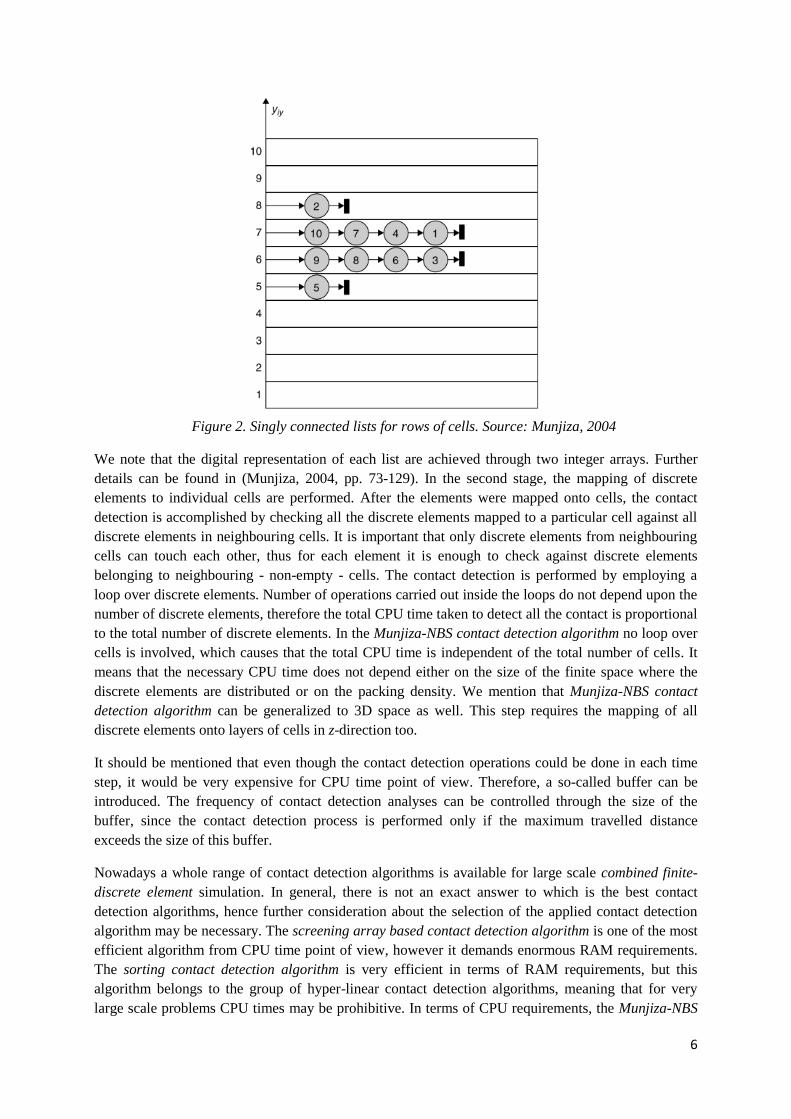
onto the rows of cells, and a singly connected list is formed for each row as it is shown in Figure (2).
6
Figure 2. Singly connected lists for rows of cells. Source: Munjiza, 2004
We note that the digital representation of each list are achieved through two integer arrays. Further
details can be found in (Munjiza, 2004, pp. 73-129). In the second stage, the mapping of discrete
elements to individual cells are performed. After the elements were mapped onto cells, the contact
detection is accomplished by checking all the discrete elements mapped to a particular cell against all
discrete elements in neighbouring cells. It is important that only discrete elements from neighbouring
cells can touch each other, thus for each element it is enough to check against discrete elements
belonging to neighbouring - non-empty - cells. The contact detection is performed by employing a
loop over discrete elements. Number of operations carried out inside the loops do not depend upon the
number of discrete elements, therefore the total CPU time taken to detect all the contact is proportional
to the total number of discrete elements. In the Munjiza-NBS contact detection algorithm no loop over
cells is involved, which causes that the total CPU time is independent of the total number of cells. It
means that the necessary CPU time does not depend either on the size of the finite space where the
discrete elements are distributed or on the packing density. We mention that Munjiza-NBS contact
detection algorithm can be generalized to 3D space as well. This step requires the mapping of all
discrete elements onto layers of cells in z-direction too.
It should be mentioned that even though the contact detection operations could be done in each time
step, it would be very expensive for CPU time point of view. Therefore, a so-called buffer can be
introduced. The frequency of contact detection analyses can be controlled through the size of the
buffer, since the contact detection process is performed only if the maximum travelled distance
exceeds the size of this buffer.
Nowadays a whole range of contact detection algorithms is available for large scale combined finite-
discrete element simulation. In general, there is not an exact answer to which is the best contact
detection algorithms, hence further consideration about the selection of the applied contact detection
algorithm may be necessary. The screening array based contact detection algorithm is one of the most
efficient algorithm from CPU time point of view, however it demands enormous RAM requirements.
The sorting contact detection algorithm is very efficient in terms of RAM requirements, but this
algorithm belongs to the group of hyper-linear contact detection algorithms, meaning that for very
large scale problems CPU times may be prohibitive. In terms of CPU requirements, the Munjiza-NBS
7
contact detection algorithm is more efficient than the binary search based contact detection
algorithms or the sorting contact detection algorithms. Although, it uses less RAM space than the
binary search based algorithm, the sorting contact detection algorithms are a little bit more efficient
in terms of RAM requirements. We note that the Munjiza-NBS contact detection algorithm and the
sorting contact detection algorithms have RAM requirements proportional to the number of discrete
elements. Eventually, the author mention that some further effective and new contact detection
algorithm can be found in the literature, referring to papers (Munjiza, Rougier, & John, 2006) and
(Schiava D'Albano, Munjiza, & Lukas, 2013).
CONTACT INTERACTION ALGORITHMS
As it has been mentioned earlier, in case of combined finite-discrete element simulations it is
absolutely essential to have an efficient and robust algorithm for handling mechanical contacts. Once
elements in contact are detected due to the applied contact detection algorithm, a contact interaction
algorithm is employed to evaluate the contact forces. Therefore, contact interaction is the
mathematical model to compute the penetration of a discrete element into another discrete element.
After calculating the penetration, contact forces are evaluated using certain constitutive relations. In
case of FEM/DEM applications the treatment of contact interaction has a special importance. Since a
combined finite-discrete element simulation may contain millions of deformable separate bodies which
can fracture and fragment, the topology and even the size of the problem change continuously, thus
handling of contacts defines the constitutive behaviour of the system. Therefore, special attention must
be paid on contact kinematics and robustness in order to obtain realistic distribution of contact forces
and energy balance.
In case of algorithms based on so-called concept of the contact element described in (Munjiza, Owen,
& Bicanic, 1995) these requirements are not satisfied entirely. When the overlap of discrete elements
in contact exceeds the contact layer, the energy balance is not preserved and the same is true when
new surfaces are created due to fracture and fragmentation processes. Furthermore, in this concept
concentrated contact forces are considered, which causes stress and strain concentrations near the
boundary of elements. These stress concentrations may result in significantly unrealistic fracture and
fragmentation behaviour especially in case of brittle materials.
Recognizing these phenomena the so-called potential field-based penalty function method was
introduced (Munjiza & Andrews, 2000). Here the basic assumption is that when two bodies in contact
penetrate each other, this penetration results in a contact force. For further calculations, a standard
contact functional was implemented in the following way:
where is the penalty term while and are position vectors of the points on the overlapping
boundaries of the target and contactor bodies, respectively. In case of infinite penalty terms no
penetration would occur, however large penalty term may cause numerical problems, thus in practical
applications the penalty function method usually works with overlaps between discrete elements in
contact. In this potential contact force concept distributed contact forces are considered which are
evaluated from the shape and the size of overlap between the so-called contactor and target elements
which form the contact. It is assumed that in the situation of elementary penetration where the
overlapping area is , an infinitesimal contact force arises given by:
8
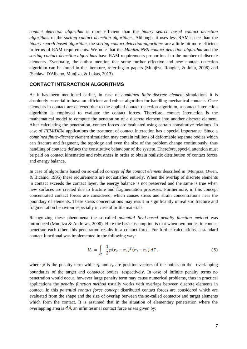
where df is the infinitesimal contact force, due to the overlap defined by overlapping points -
belonging to the contactor - and - belonging to the target. As it is shown in Eq. (6), the contact can
be viewed firstly as the elemental area of the contactor penetrating the target and then the elemental
area of the target penetrating the contactor. The previous formula also shows that the contact force can
be calculated as the gradient of the corresponding potential function, thus contact forces form a
conservative vector field. Due to this fact, if point of the contactor element penetrates the target
through any path defined by end point and , the total work of the contact force does not depend on
path but on the end points only and it is given as .
Figure 3 Contact force due to an infinitesimal overlap around points and
Source: Munjiza, 2004
An important aspect is that when point and are placed on the boundary of the target discrete
element, a contact-contact release situation arises, when the energy preservation law requires that no
work is done by the contact force, ie.:
Therefore, if Eq. (7) is valid for every arbitrary boundary points of the contactor and target elements,
then the contact force given by Eq. (6) preserves the energy balance regardless of the geometry or the
shape of the contacting elements, the size of the overlap or the value of the penalty term. Afterwards
the total contact force is obtained by integrating the elementary forces defined in Eq. (6) over the
overlapping area as it is shown in Eq. (8).
This integral can be transformed into a line integral over the boundary of the overlapping area :
where is the outward unit normal to the boundary of the overlapping area.
9
Since in the FEM/DEM individual discrete elements are discretized into finite elements, the previous
integrals can be represented by the summation over finite elements as it is shown in Eq. (10) and Eq.
(11).
Hence, the contact force between overlapping discrete elements can be calculated by a summation
over the edges of corresponding finite elements that overlap.
We mention, that in 3D the integral over the overlapping volume must be performed as it is shown in
Eq. (12).
By replacing integration over finite elements by equivalent integration over finite element boundaries,
the following equation for contact fore is obtained:
Thus, the contact force between overlapping discrete elements is calculated by summation over the
surfaces of corresponding finite elements that overlap, where is the outward unit normal to the
surface of the overlapping volume.
As a summary, it was shown that using contact interaction algorithm based on the potential field-based
penalty function method has several advantages. It works with distributed contact forces, thus no
artificial stress concentrations arises due to the contact, which would cause unrealistic fracturing
behaviour. Furthermore, these algorithms satisfy the energy preservation which is an essential
requirement in simulating physical behaviour properly. Due to this fact, the application of any kind of
artificial damping is unnecessary. This potential force concept allows easy sliding between contact
surfaces, and accurate representation of the physical contact conditions onto which friction, sliding,
plasticity, surface roughness, wet-dry conditions, etc. can be incorporated following relatively simple
rules of potential distribution over the finite element. This technique uses only the data supplied in the
in-core database for contact free finite element analysis and it is easily linked to contact detection
algorithm such as Munjiza-NBS contact detection algorithm. The algorithm does not require detection
of boundary surfaces and the contact force is discretised with the same algorithm and the same piece
of code, regardless of the shape of discrete elements thus, algorithmic complexities are greatly
reduced. All of these reasons lead to fact that this type of contact processing is in general faster than
alternative solutions. For further details we refer to the book (Munjiza, 2004, pp. 35-72).
DEFORMABILITY OF ELEMENTS
10
As from the basic idea of the combined finite-discrete element method follows, the continuum
behaviour (i.e. the deformability) of discrete elements are described with the means of the finite
element method. Each discrete element has its own finite element mesh which is able to follow the
deformations of the discrete element. Furthermore, as it was shown earlier, the finite element
discretization of individual discrete elements describes the contact conditions between discrete
elements due to the discretization of the distributed contact forces.
To describe the deformations of discrete elements, the classical equations and tensors of the
continuum mechanics are used. Therefore, the current coordinates x of material points having
reference position vector p can be written as:
where is the displacement of material point. Deformations are described with the help of a strain
tensor calculated from the deformation gradient tensor :
Typically, in a FEM/DEM simulation the well known strain measures of continuum mechanics for
instance, the right- and left Cauchy-Green, Green-St. Venant, Almansi-Hamel strain tensors, etc. are
used. Although in most cases it is enough to consider small strains, it is very important to note that in
FEM/DEM simulations large displacements must be followed. In such a case when the stretches are
small but the rotations and displacements are large it is practical to decompose the deformation
gradient tensor in the following way:
where is the right stretch tensor, is the left stretch tensor and is the orthogonal rotation tensor.
Following the polar decomposition of the deformation gradient tensor, the right Green-St. Venant
strain tensor can be expressed as:
The application of right stretch tensor physically means that the material is first stretched in the
principal directions and it is followed by the rotation. The reverse procedure can be performed by
using the left stretch tensor . Here the left Green-St. Venant strain tensor is applied as:
In this case, the rotation occurs first, then the stretches already occur in the principal directions of the
rotated configuration.
In order to measure the stress variables the Cauchy, First- or Second Piola-Kirchhoff stress tensors
can be applied. In the calculations some kinds of constitutive relations are applied which make
connection between stresses and strains and contain failure criteria. Discussion of further details about
the typical steps of continuum mechanics is out of the scope of this chapter. Additional details can be
found for instance, in (Munjiza, 2004, pp. 131-177) and (Belytschko, Liu, & Moran, 2000, pp. 75-
137).
11
Since the finite element discretization is also used to process contact interaction, in general, it is
important to employ as simple geometry of finite elements as possible in order to obtain efficient
contact interaction algorithm. Due to this fact, mainly constant strain triangle finite elements are used
in 2D and constant strain tetrahedron elements are used in case of 3D analyses. However in case of
relatively incompressible solids, locking problems are associated with these linear finite elements
which can seriously degrade the accuracy of the simulations. Therefore, in the paper (Xiang, Munjiza,
& Latham, 2009), finite strain, finite rotation quadratic tetrahedral elements were implemented into the
FEM/DEM.
FRACTURE AND FRAGMENTATION ALGORITHMS
The appropriate modelling of transition from continua to discontinua processes including fracture and
fragmentation plays an essential role in a FEM/DEM analysis. In order to describe these phenomena
so-called fracture and fragmentation algorithms are used which handle the creation of new boundaries
and new discrete elements under certain loading conditions.
A fracture and fragmentation algorithm is responsible to solve several tasks. Namely, it has to describe
the conditions under crack initiation appears, and the way how it propagates. During the crack
propagation remeshing is necessary, thus variables must be transformed from the old mesh to the new
one. Additionally, released internal forces must be replaced with equivalent contact forces.
Several different approaches exist how to perform the analysis of cracks. The global approach is based
on the representation of the stress singularity at the crack tip. This singularity can be characterized by
the energy release rate . However local approaches usually apply a smeared crack approach, where
the crack is replaced by a blunt crack band and the crack propagation processes are described with the
help of constitutive laws or formulations of damage mechanics. Furthermore, the single crack
approach considers a plastic zone at the crack tip, and the plastically strained material is replaced by a
zone of weakened bonds between the crack walls. In the combined finite-discrete element method a
fracture based softening plasticity framework is applied, where the energy dissipation is considered
through a mesh size dependent softening modulus as it is detailed in (Munjiza, Owen, & Bicanic,
1995). After further research (Munjiza, Andrews, & White, 1999) the combination of smeared and
single crack approaches was implemented. The aim of this coupling was to model multiple-crack, and
progressive fracture situations. In this combined single and smeared crack model the strain-hardening
part of the stress-strain curve is considered through constitutive laws, while the strain-softening part is
treated by the softening stress-displacement relationship being implemented through the single crack
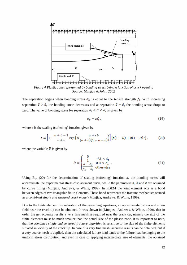
model as it can be seen in Figure (4). In this approach, the plastic zone is represented by bonding
stress being the function of crack opening.
12
Figure 4 Plastic zone represented by bonding stress being a function of crack opening
Source: Munjiza & John, 2002
The separation begins when bonding stress is equal to the tensile strength . With increasing
separation the bonding stress decreases and at separation the bonding stress drops to
zero. The value of bonding stress for separation is given by
where is the scaling (softening) function given by
where the variable is given by
Using Eq. (20) for the determination of scaling (softening) function , the bonding stress will
approximate the experimental stress-displacement curve, while the parameters , and are obtained
by curve fitting (Munjiza, Andrews, & White, 1999). In FDEM the joint element acts as a bond
between edges of two triangular finite elements. These bond represents the fracture mechanism termed
as a combined single and smeared crack model (Munjiza, Andrews, & White, 1999).
Due to the finite element discretization of the governing equations, an approximated stress and strain
field near the crack tip can be obtained. It was shown in (Munjiza, Andrews, & White, 1999), that in
order the get accurate results a very fine mesh is required near the crack tip, namely the size of the
finite elements must be much smaller than the actual size of the plastic zone. It is important to note,
that the combined single and smeared fracture algorithm is sensitive to the size of the finite elements
situated in vicinity of the crack tip. In case of a very fine mesh, accurate results can be obtained, but if
a very coarse mesh is applied, then the calculated failure load tends to the failure load belonging to the
uniform stress distribution, and even in case of applying intermediate size of elements, the obtained
13
critical load will be overestimated. Beside the enormous computational challenge caused by contact
detection, contact interaction algorithms, and time integration, the fracture and fragmentation
algorithms provides a huge computational task additionally, which – at least nowadays - may restrict
the application of the combined finite-discrete element method in case of large-scale engineering
problems.
TIME INTEGRATION
In order to reduce the CPU time, explicit time integration schemes may be applied. As it was
mentioned earlier, the so-called lumped mass matrix approach is used, thus diagonal mass matrix is
considered during the analysis. Furthermore, the assembling of stiffness matrix can also be avoided by
using an explicit time integration scheme. Traditionally, the central difference method has been
employed to solve the equation of motion. Since it is a conditionally stable technique, the stability and
the required accuracy are achieved through reducing the size of the time step. As an alternative
technique the Gear's predictor-corrector time integration schemes should be mentioned. These
schemes always includes three stages, namely:
- Prediction stage, where the positions of the elements are calculated at using Taylor
series based on positions and their time derivatives.
- Evaluation stage, where the forces are evaluated based on the position of the elements
calculated in the prediction stage. From this force, the accelerations at can be calculated,
and difference can be determined between the predicted and the calculated accelerations.
- Correction stage, where the predicted positions and its time derivatives are corrected using the
discrepancy between accelerations calculated in the evaluation stage.
It should be mentioned that in the book (Munjiza, 2004, pp. 203-208) further alternative explicit time
integration techniques, for instance CHIN,OMF30 and OMF32 integration schemes are detailed. All
of these techniques can be used in a FEM/DEM simulation. The decision about which scheme should
be used depends on their efficiency in terms of stability, accuracy and CPU time. In the book
(Munjiza, 2004, pp. 208-211), a comparison analysis can be found for a single degree of freedom
system. It was shown that although in some cases the higher order methods work with larger values of
critical time steps, still the higher order methods not necessarily faster than lower order schemes. This
conclusion is especially true in case of large scale systems, where contact detection, contact
interaction, fracture and fragmentation may be involved, and higher order schemes require multiple
force evaluation which is much less efficient than lower order methods.
PARALLELIZATION
As it has been mentioned, the limitation of FEM/DEM is that it is CPU-intensive, thus it is difficult to
analyze large scale problems on sequential CPU hardware. Therefore, researches (Owen, Feng, Han,
& Peric, 2000), (Owen & Feng, 2001), (Wang, Feng, & Owen, 2004)] were carried out in order to
implement the possibility to use high-performance parallel computers. In all those studies, a
master/slave approach was adopted meaning that one master processor was performing domain
decomposition and load balancing tasks, then distributing work to slave processors. Some general
strategies for parallelization of FEM/DEM are described in (Munjiza, Knight, & Rougier, 2012). Later,
other versions appeared as static domain decomposition (Schiava D'Albano, 2014), hardware
independent FEM/DEM parallelization framework by using virtual parallel machine (Lei, Rougier,
Knight, & Munjiza, 2014), and dynamic domain decomposition based parallelization where all tasks
(domain decomposition, load balancing) are performed concurrently on all processors (Lukas, Schiava
14
D'Albano, & Munjiza, 2014). Parallelization strategies usually attempt to divide the large problem
(computational domain) into a number of smaller sub-problems (sub-domains). A good parallel
implementation has to fulfil two - often competing - requirements, namely each processor must be
kept busy doing useful work and the communication between processors must be kept to a minimum.
Today, parallelization algorithms are available in FEM/DEM codes, thus - at least in many cases - the
solution of large scale problems became possible.
EXAMPLES FOR COMBINED FINITE-DISCRETE ELEMENT SIMULATIONS
In the following, some examples are mentioned for the application of the combined finite-discrete
element method. This part focuses on the modelling of masonry structures, however other applications
are shortly mentioned as well.
Firstly, referring to the paper (Nikolic, Smoljanovic, & Zivaljic, 2013), seismic analysis of dry stone
masonry structures were performed with the help of the FEM/DEM. In this work each stone block was
modelled as a discrete element which was discretized by constant strain triangular finite elements. The
fracture and fragmentation processes were considered through contact elements which were
implemented within the finite element mesh. In the applied FEM/DEM code the Munjiza-NBS contact
detection algorithm was implemented. In the contact interaction algorithm the potential contact force
concept was applied and the Coulomb-type condition was used to analyze the friction between discrete
elements. The cracks were assumed to coincide with the finite element edges and the separation of
these edges induced a bonding stress which was taken to be a function of the size of the separation. At
first, numerical calculations for the analysis of shear behaviour of stone masonry joints were
performed. Two different pre-compression stresses were applied and after shear tests were carried out
under displacement control and the numerical results showed a great correspondence with the
experimental results. Afterwards the behaviour of existing structures were analysed under seismic
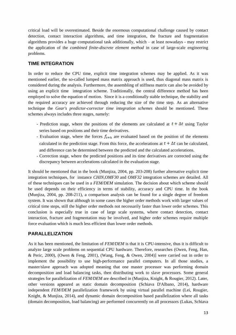
effects. The dynamic response of the structure of the Prothyron - which is a certain part of Diocletian's
Palace in Split - was simulated with the combined finite-discrete element method. The FEM/DEM
model of the structure can be seen in Figure (5).
Figure 5 FEM/DEM model of Prothyron including discrete elements (left) and FEM mesh (right)
Source: Nikolic, Smoljanovic, & Zivaljic, 2013
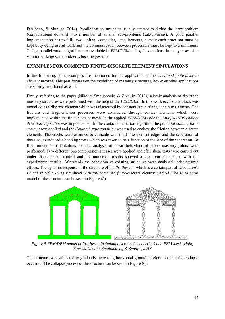
The structure was subjected to gradually increasing horizontal ground acceleration until the collapse
occurred. The collapse process of the structure can be seen in Figure (6).
15
Figure 6 Collapse simulation of Prothyron due to seismic effect using FEM/DEM
Source: Nikolic, Smoljanovic, & Zivaljic, 2013
This research (Nikolic, Smoljanovic, & Zivaljic, 2013) showed the advantage of using the combined
finite-discrete element method - which derives from the possibility of modelling the fragmentation of
blocks - for analysis of failure modes of structures under hazardous loads. The results of the performed
analyses showed good agreement with the experiments, thus this paper demonstrates the potential of
the FEM/DEM for realistic modelling of the response of dry masonry structures. Further details can be
found in the original paper (Nikolic, Smoljanovic, & Zivaljic, 2013).
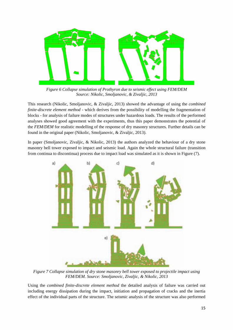
In paper (Smoljanovic, Zivaljic, & Nikolic, 2013) the authors analyzed the behaviour of a dry stone
masonry bell tower exposed to impact and seismic load. Again the whole structural failure (transition
from continua to discontinua) process due to impact load was simulated as it is shown in Figure (7).
Figure 7 Collapse simulation of dry stone masonry bell tower exposed to projectile impact using
FEM/DEM. Source: Smoljanovic, Zivaljic, & Nikolic, 2013
Using the combined finite-discrete element method the detailed analysis of failure was carried out
including energy dissipation during the impact, initiation and propagation of cracks and the inertia
effect of the individual parts of the structure. The seismic analysis of the structure was also performed

16
which enables the determination of the load bearing capacity and the behaviour factor of the structure.
The collapse simulation under seismic effects can be seen in Figure (8).
Figure 8 Collapse simulation of dry stone masonry bell tower exposed to seismic effects using
FEM/DEM. Source: Smoljanovic, Zivaljic, & Nikolic, 2013
In the paper (Smoljanovic, Zivaljic, & Nikolic, 2013) the advantage of the combined finite-discrete
element method in performing collapse simulations were shown. The applied numerical model was
able to simulate the whole structural failure process including large displacements and rotations of
stone blocks subjected to friction force acting between them. Further details of the analyses can be
found in the original paper (Smoljanovic, Zivaljic, & Nikolic, 2013) including numerical analyses of
reinforced concrete structures as well.
In the paper (Baraldi, Reccia, Cazzani, & Cecchi, 2013) a comparative study is discussed. Discrete
models and FEM/DEM models were used to investigate the in-plane behaviour of periodic brickwork.
In the FEM/DEM simulations elastic blocks were considered by means of finite elements, but on the
other hand, rigid discrete elements were applied in the discrete model. In the FEM/DEM model the
mortar joints were idealized as elastic or elasto-plastic zero-thickness Mohr-Coulomb interfaces. Two
different joint types were applied in the FEM/DEM simulations. One of these was implemented inside
the block and this worked with a high cohesion value in order to avoid the breaking of blocks,
however a much smaller cohesion value was applied for joints placed between the blocks in order to
model the separation of blocks along the mortar joints. In this paper (Baraldi, Reccia, Cazzani, &
17
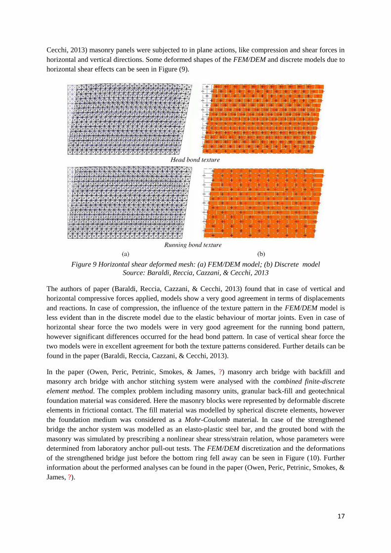
Cecchi, 2013) masonry panels were subjected to in plane actions, like compression and shear forces in
horizontal and vertical directions. Some deformed shapes of the FEM/DEM and discrete models due to
horizontal shear effects can be seen in Figure (9).
Figure 9 Horizontal shear deformed mesh: (a) FEM/DEM model; (b) Discrete model
Source: Baraldi, Reccia, Cazzani, & Cecchi, 2013
The authors of paper (Baraldi, Reccia, Cazzani, & Cecchi, 2013) found that in case of vertical and
horizontal compressive forces applied, models show a very good agreement in terms of displacements
and reactions. In case of compression, the influence of the texture pattern in the FEM/DEM model is
less evident than in the discrete model due to the elastic behaviour of mortar joints. Even in case of
horizontal shear force the two models were in very good agreement for the running bond pattern,
however significant differences occurred for the head bond pattern. In case of vertical shear force the
two models were in excellent agreement for both the texture patterns considered. Further details can be
found in the paper (Baraldi, Reccia, Cazzani, & Cecchi, 2013).
In the paper (Owen, Peric, Petrinic, Smokes, & James, ?) masonry arch bridge with backfill and
masonry arch bridge with anchor stitching system were analysed with the combined finite-discrete
element method. The complex problem including masonry units, granular back-fill and geotechnical
foundation material was considered. Here the masonry blocks were represented by deformable discrete
elements in frictional contact. The fill material was modelled by spherical discrete elements, however
the foundation medium was considered as a Mohr-Coulomb material. In case of the strengthened
bridge the anchor system was modelled as an elasto-plastic steel bar, and the grouted bond with the
masonry was simulated by prescribing a nonlinear shear stress/strain relation, whose parameters were
determined from laboratory anchor pull-out tests. The FEM/DEM discretization and the deformations
of the strengthened bridge just before the bottom ring fell away can be seen in Figure (10). Further
information about the performed analyses can be found in the paper (Owen, Peric, Petrinic, Smokes, &
James, ?).

18
Figure 10 FEM/DEM discretization of masonry arch bridge (a); Deformations just before the
collapse. Source: (Owen, Peric, Petrinic, Smokes, & James, ?)
Apart from the numerical simulations of structures the combined finite-discrete element method
proved to be a very effective tool in case of biomechanical applications as well. We refer for instance,
to the paper (Xu et al., 2013), where large scale simulations of red blood cell aggregation in shear
flows were performed with the help of FEM/DEM.
CONCLUSION
In this chapter the main characteristics and steps of the combined finite-discrete element method were
discussed. The specific contact detection, contact interaction, fracture and fragmentation algorithms
were mentioned, which are typically used in FDEM simulations. Furthermore, the huge computational
challenge in case of large scale problems were pointed out, and the time stepping process with certain
parallelization techniques were shortly mentioned. Examples were collected from the literature, where
the authors proved the efficiency of the combined finite-discrete element method in the appropriate
modelling of masonry structures.
ADDITIONAL READINGS
As a final remark, for the interested readers, the presence of open source combined finite-discrete
element codes, Y2D and Y3D should be mentioned. These codes include the above mentioned
algorithms and have already served as a basic tool in case of several FEM/DEM researches.
Additionally, Y-GUI graphical user interface is available (Mahabadi, Grasselli, & Munjiza, 2010),
which provides the possibility to set up models graphically, instead typing the entire input file in
ASCII text editor, significantly reducing the time needed to create the geometry of the model. Further
information can be found on the following website: http://vgest.net/.
REFERENCES
Baraldi, D., Reccia, E., Cazzani, A., & Cecchi, A. (2013) Discrete and finite element models
for periodic brickwork: a comparative analysis. Paper presented at AIMETA, Torino,
Italy.
Belytschko, T., Liu, W. K., & Moran, B. (2000) Nonlinear finite elements for continua and
structures. John Wiley & Sons Ltd.

19
Lei, Z., Rougier, E., Knight, E.E., & Munjiza, A. (2014). A framework for grand scale
parallelization of the combined finite discrete element method in 2D. Computational
Particle Mechanics, 1(3), 307-19.
Lukas, T., Schiava D'Albano, G.G., & Munjiza, A. (2014). Space decomposition based
parallelization solutions for the combined finite-discrete element method in 2D. Journal of
Rock Mechanics and Geotechnical Engineering, 6, 607-615.
Mahabadi, O.K., Grasselli, G., & Munjiza, A. (2010). A graphical user interface and pre-
processor for the combined finite-discrete element code, Y2D, incorporating material
heterogeneity. Computers & Geosciences, 36, 241-252.
Munjiza, A. (2004). The combined finite-discrete element method. John Wiley & Sons Ltd.
Munjiza, A., & Andrews, K.R.F. (2000). Penalty function method for combined finite-discrete
element systems comprising large number of separate bodies. International Journal for
Numerical Methods in Engineering, 49, 1377-1396.
Munjiza, A., Andrews, K.R.F., & White, J.K. (1999). Combined single and smeared crack
model in combined finite-discrete element method. International Journal for Numerical
Methods in Engineering, 44, 41-57.
Munjiza, A., & John, N.W.M. (2002). Mesh size sensitivity of the combined FEM/DEM
fracture and fragmentation algorithms. Engineering Fracture Mechanics, 69, 281-295.
Munjiza, A., Knight, E.E., & Rougier, E. (2012). Computational mechanics of discontinua.
Chichester, UK: John Wiley & Sons.
Munjiza, A., Rougier, E., & John, N.W.M. (2006). MR linear contact detection algorithm.
International Journal for Numerical Methods in Engineering, 66(1).
Munjiza, A., Owen, D.R.J., & Bicanic, N. (1995). A combined finite discrete element method
in transient dynamics of fracturing solids. Engineering Computations, 12(2), 145-74.
Nikolic, Z., Smoljanovic, H., & Zivaljic, N. (2013). A combined finite-discrete element
analysis of dry stone masonry structures. Engineering Structures, 52, 89-100.
Owen, D.R.J., & Feng, Y.T. (2001). Parallelised finite/discrete element simulation of multi-
fracturing solids and discrete systems. Engineering Computations 18(3-4), 557-76.
Owen, D.R.J., Feng, Y.T., Han, K., & Peric, D. (2000). Dynamic domain decomposition and
load balancing in parallel simulation of finite/discrete elements. Paper presented at
European Congress on Computational Methods in Applied Sciences and Engineering,
Barcelona, Spain.
Owen, D.RJ., Peric, D., Petrinic, N., Smokes, CL., & James, P.J. (?). Finite/discrete element
models for assessment and repair of masonry structures, ?
Schiava D'Albano, G.G. (2014). Computational and algorithmic solutions for large scale
combined finite-discrete elements simulations. (Unpublished? doctoral dissertation).
London, UK: Queen Mary, University of London.
Schiava D'Albano, G.G., Munjiza, A., & Lukas, T. (2013). Novel MS (MunjizaSchiava)
contact detection algorithm for multi-core architectures. Paper presented at Particles,
Stuttgart, Germany.
Smoljanovic, H., Zivaljic, N., & Nikolic, Z. (2013). Nonlinear analysis of engineering
structures by combined finite-discrete element method. Gradevinar, 65, 331-334.
20
Wang, F., Feng, Y.T., & Owen, D.R.J. (2004). Parallelization for finite-discrete element
analysis in a distributed-memory environment. International Journal of Computational
Engineering Science, 5(1), 1-23.
Xiang, J., Munjiza, A., & Latham, J.-P. (2009). Finite strain, finite rotation quadratic
tetrahedral element for the combined finite-discrete element method. International Journal
for Numerical Methods in Engineering, 79(8), 946-978.
Xu, D., Kaliviotis, E., Munjiza, A., Avital, E., Ji, C., & Williams, J. (2013). Large scale
simulation of red blood cell aggregation in shear flows. Journal of Biomechanics, 46,
1810-1817.