Embed Size (px)
Citation preview
Introduction to Filters
Section 14.1-14.2
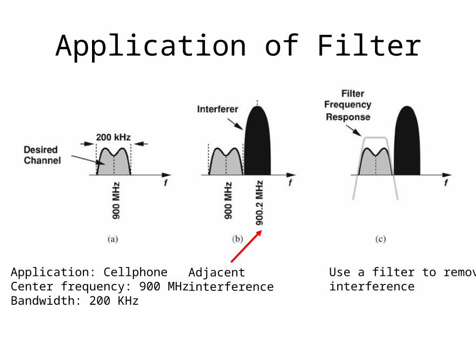
Application of Filter
Application: CellphoneCenter frequency: 900 MHzBandwidth: 200 KHz
Adjacent interference
Use a filter to removeinterference
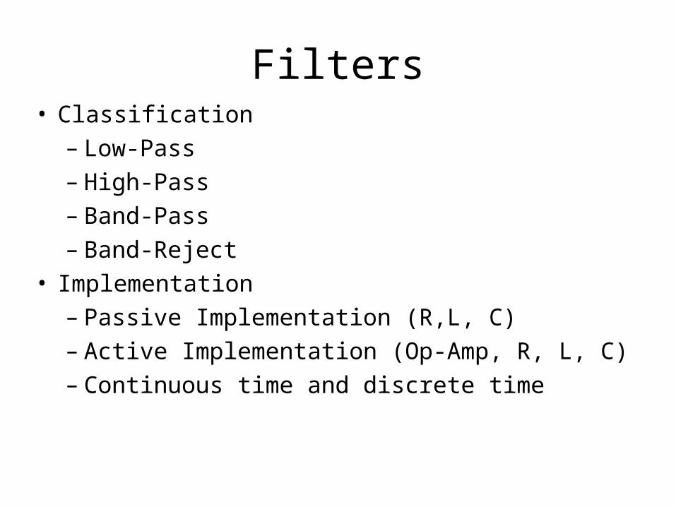
Filters• Classification
– Low-Pass– High-Pass– Band-Pass– Band-Reject
• Implementation– Passive Implementation (R,L, C)– Active Implementation (Op-Amp, R, L, C)– Continuous time and discrete time
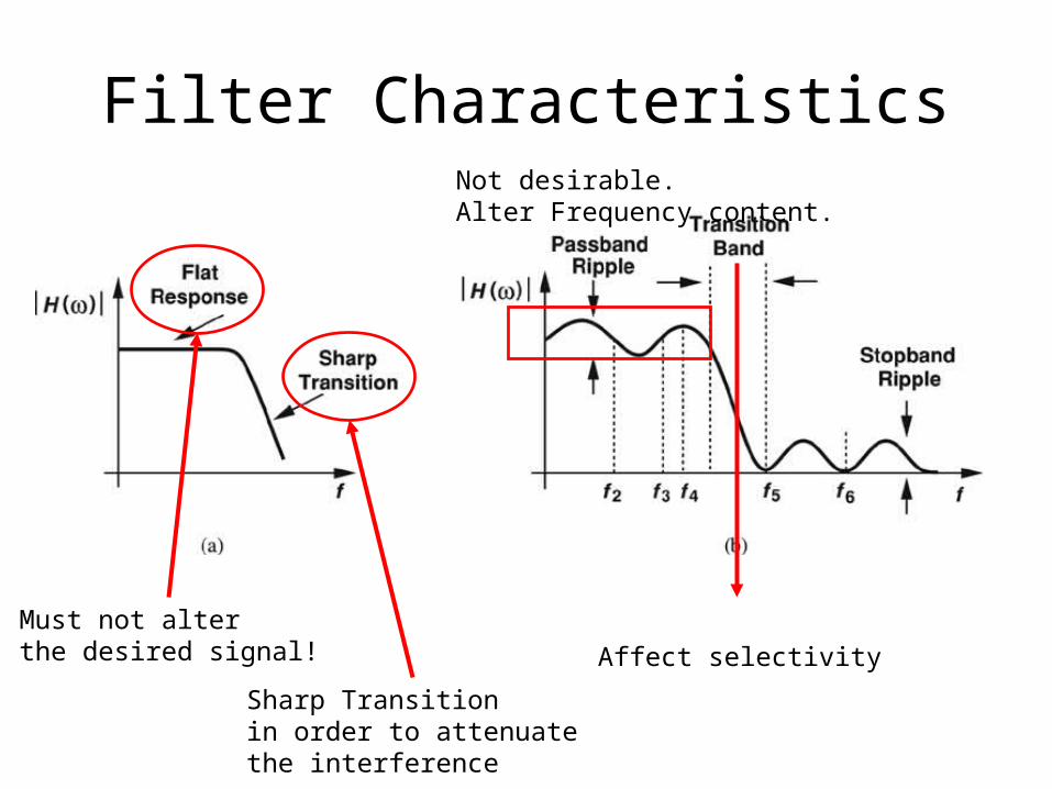
Filter Characteristics
Must not alter the desired signal!
Sharp Transitionin order to attenuatethe interference
Not desirable.Alter Frequency content.
Affect selectivity
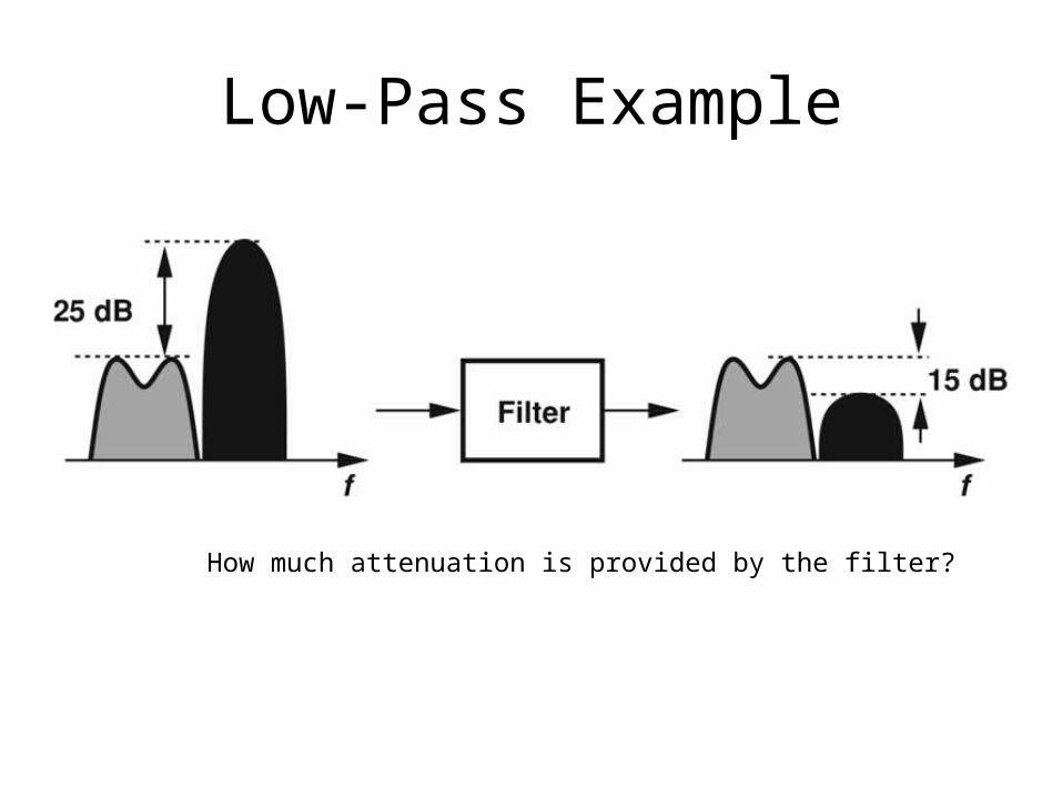
Low-Pass Example
How much attenuation is provided by the filter?
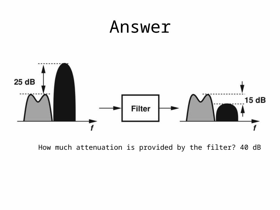
Answer
How much attenuation is provided by the filter? 40 dB
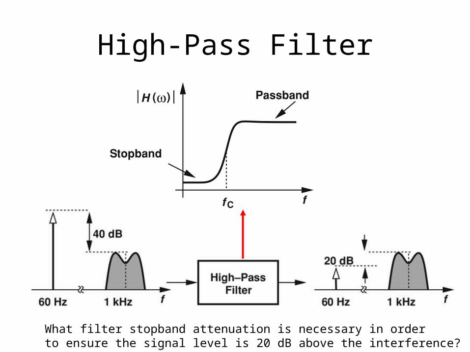
High-Pass Filter
What filter stopband attenuation is necessary in orderto ensure the signal level is 20 dB above the interference?
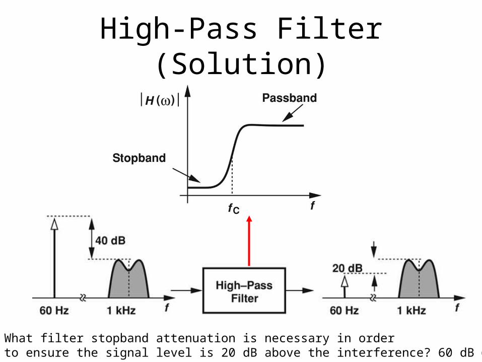
High-Pass Filter (Solution)
What filter stopband attenuation is necessary in orderto ensure the signal level is 20 dB above the interference? 60 dB @60 Hz
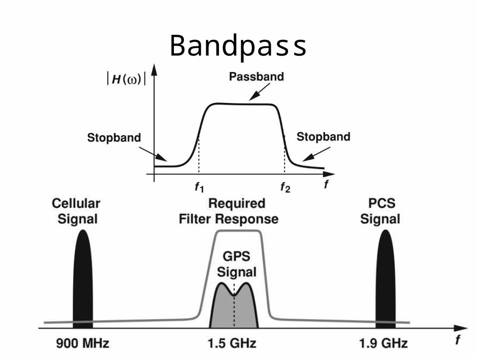
Bandpass
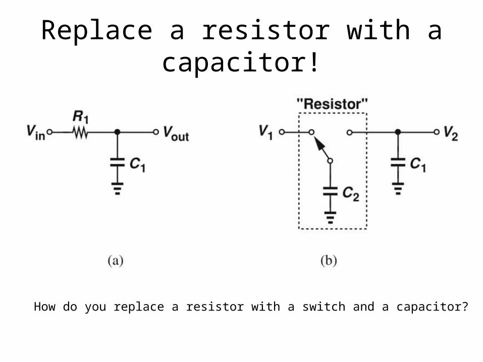
Replace a resistor with a capacitor!
How do you replace a resistor with a switch and a capacitor?
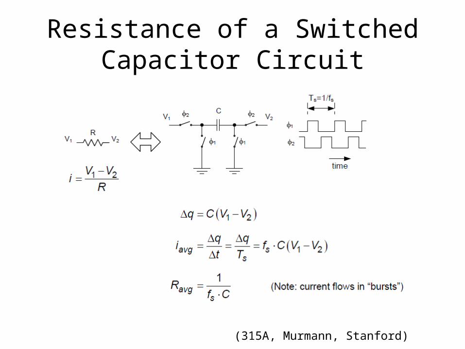
Resistance of a Switched Capacitor Circuit
(315A, Murmann, Stanford)
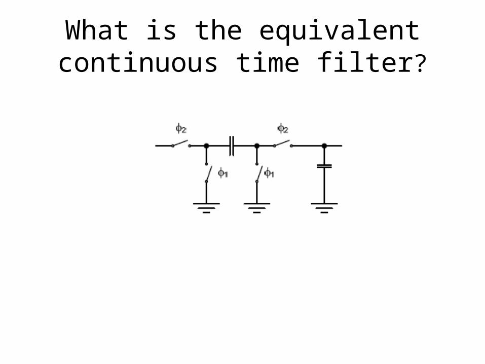
What is the equivalent continuous time filter?
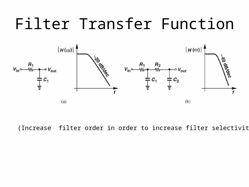
Filter Transfer Function
(Increase filter order in order to increase filter selectivity!)
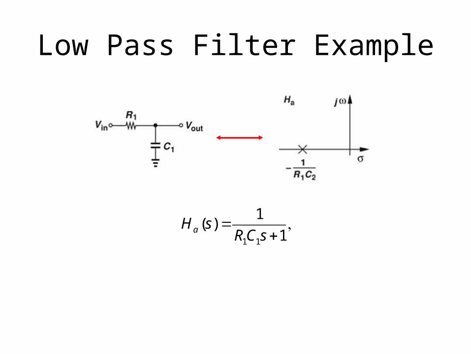
Low Pass Filter Example
1 1
1( )
1aH sRC s
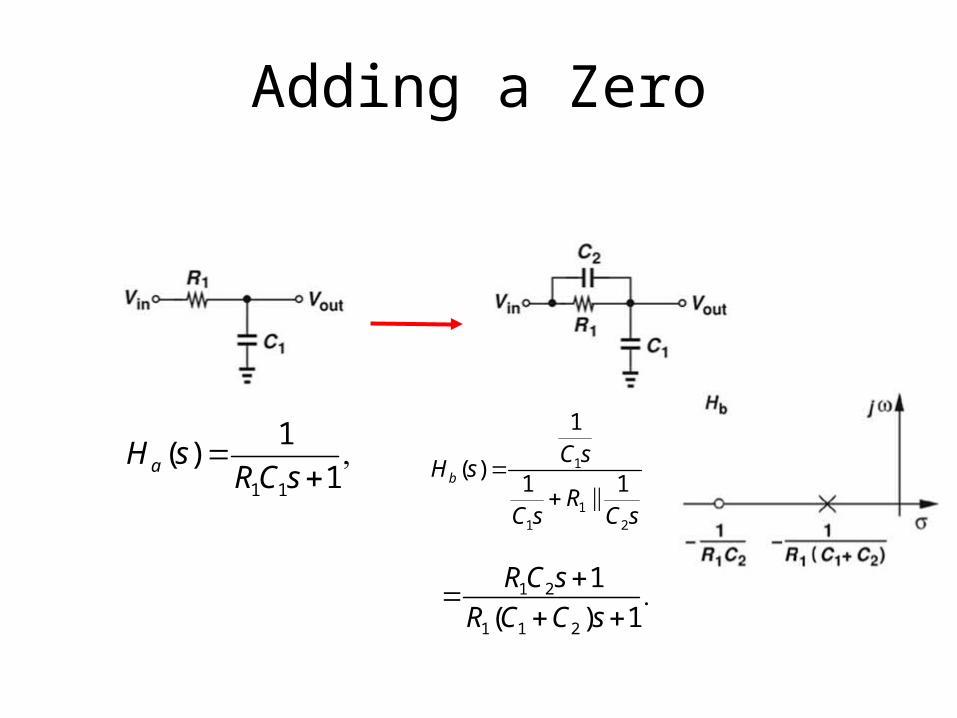
Adding a Zero
1 1
1( )
1aH sRC s
1
11 2
1
( )1 1b
C sH s
RC s C s
1 2
1 1 2
1
( ) 1
RC s
R C C s
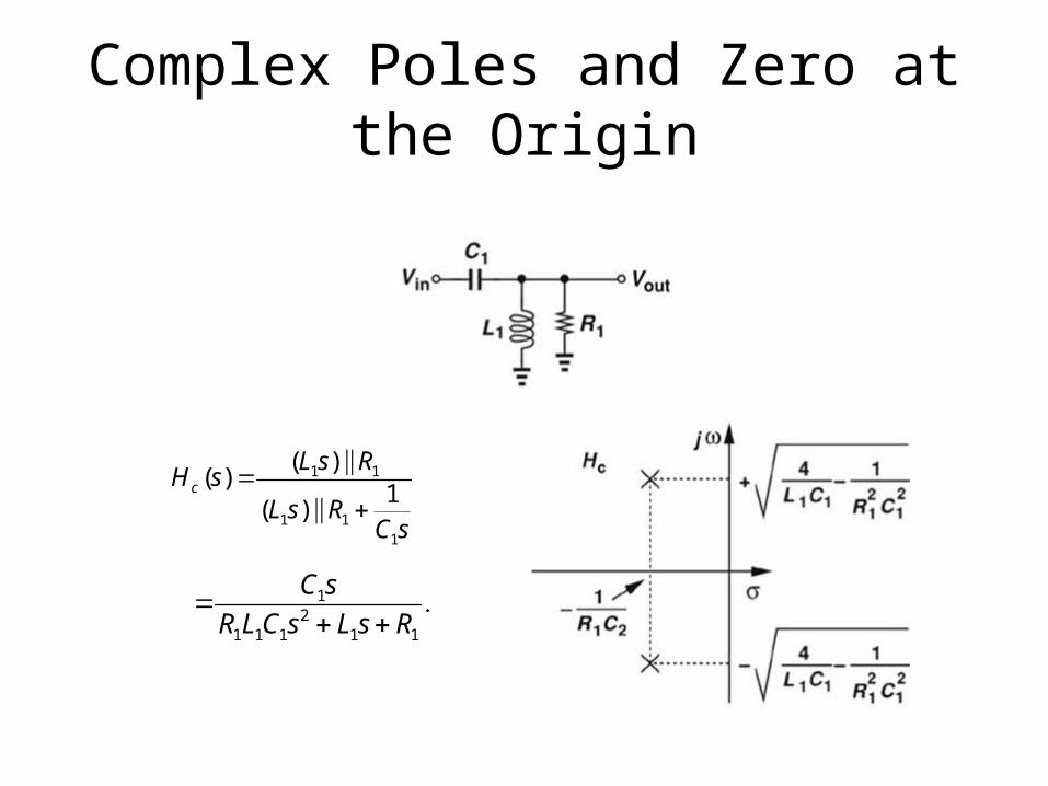
Complex Poles and Zero at the Origin
1 1
1 11
( )( )
1( )
c
L s RH s
L s RC s
12
1 1 1 1 1
C s
R LC s L s R
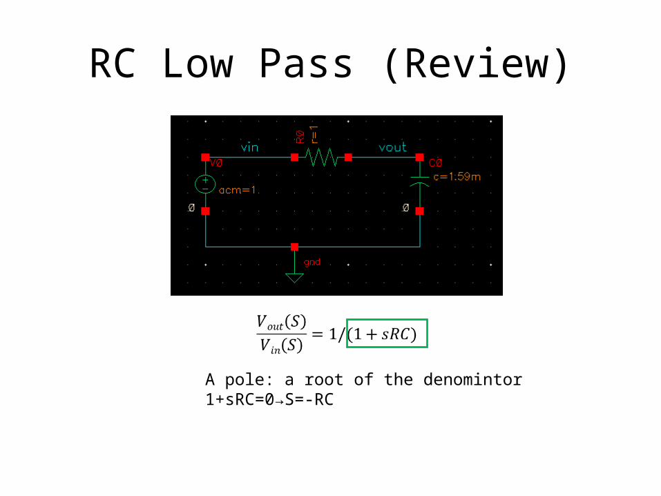
RC Low Pass (Review)
A pole: a root of the denomintor1+sRC=0→S=-RC
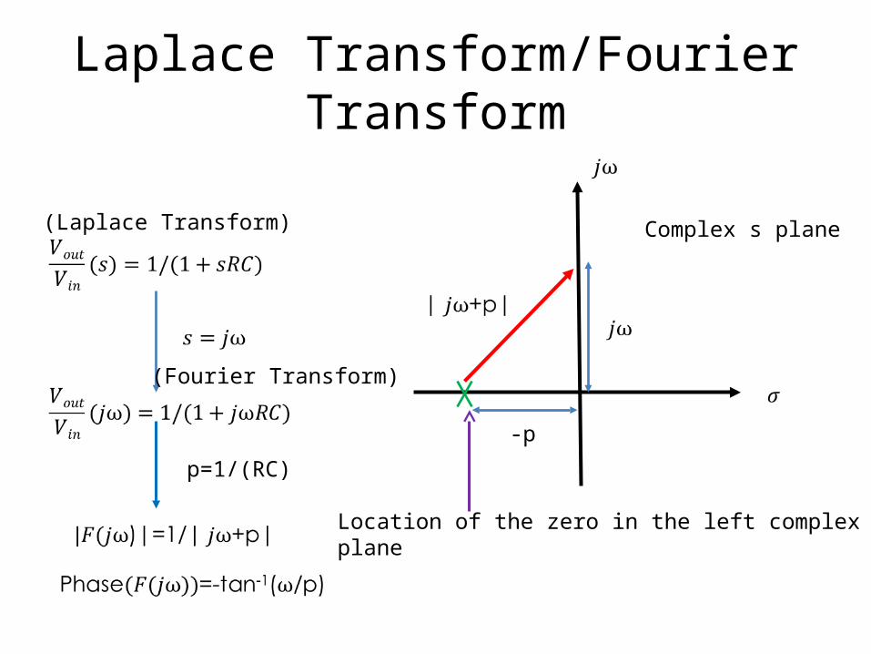
Laplace Transform/Fourier Transform
p=1/(RC)
(Fourier Transform)
(Laplace Transform)
-p
Location of the zero in the left complexplane
Complex s plane

Rules of thumb: (applicable to a pole)Magnitude:1.20 dB drop after the cut-off frequency2.3dB drop at the cut-off frequencyPhase:1.-45 deg at the cut-off frequency2.0 degree at one decade prior to the cut-frequency3.90 degrees one decade after the cut-off frequency
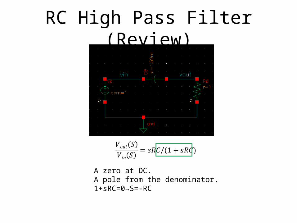
RC High Pass Filter (Review)
A zero at DC.A pole from the denominator.1+sRC=0→S=-RC
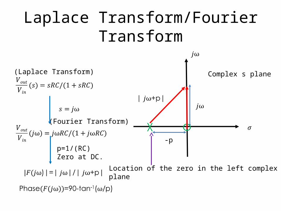
Laplace Transform/Fourier Transform
p=1/(RC)Zero at DC.
(Fourier Transform)
(Laplace Transform)
-p
Location of the zero in the left complexplane
Complex s plane
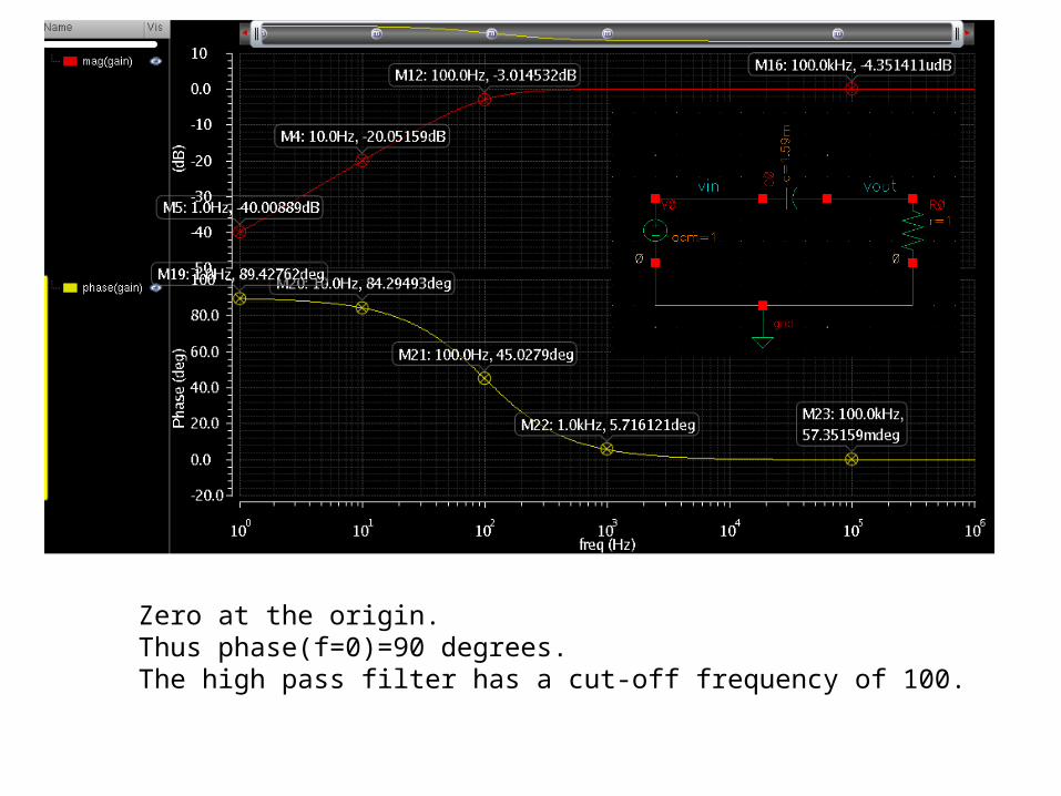
Zero at the origin.Thus phase(f=0)=90 degrees.The high pass filter has a cut-off frequency of 100.
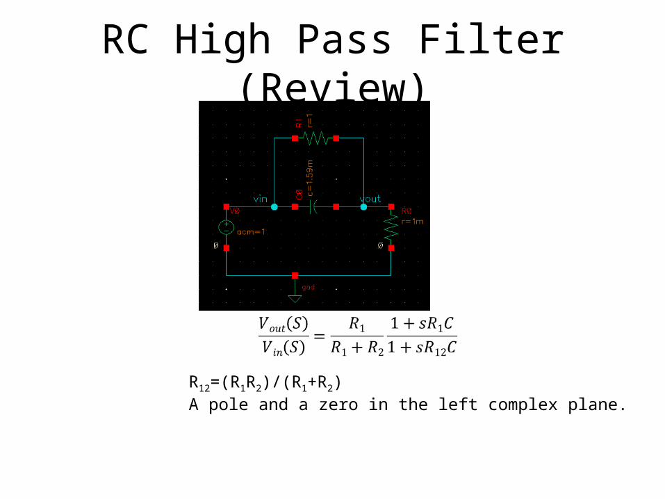
RC High Pass Filter (Review)
R12=(R1R2)/(R1+R2)A pole and a zero in the left complex plane.
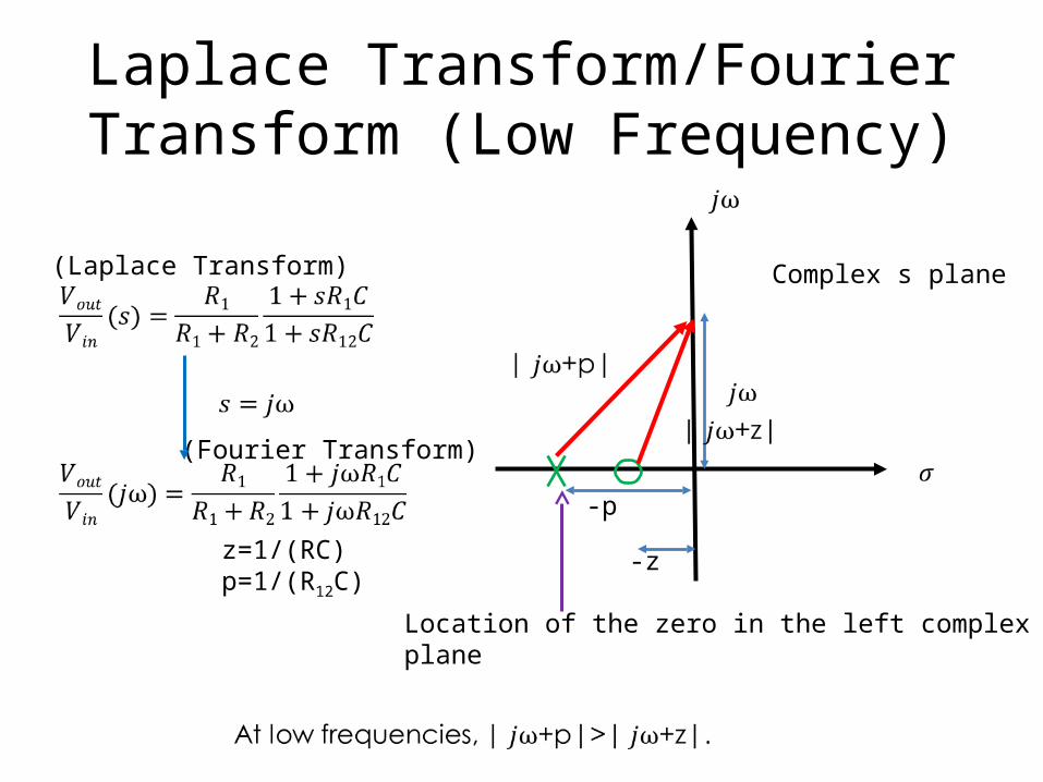
Laplace Transform/Fourier Transform (Low Frequency)
z=1/(RC)p=1/(R12C)
(Fourier Transform)
(Laplace Transform)
-p
Location of the zero in the left complexplane
Complex s plane
-z
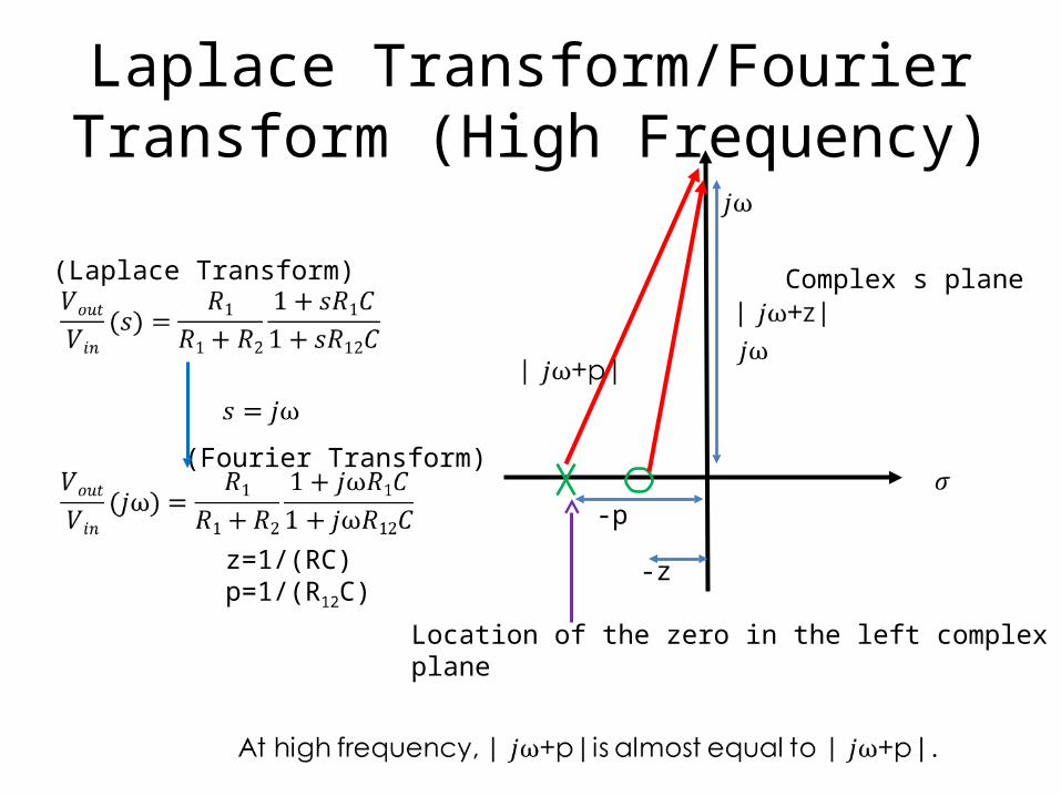
Laplace Transform/Fourier Transform (High Frequency)
z=1/(RC)p=1/(R12C)
(Fourier Transform)
(Laplace Transform)
-p
Location of the zero in the left complexplane
Complex s plane
-z
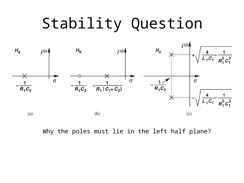
Stability Question
Why the poles must lie in the left half plane?
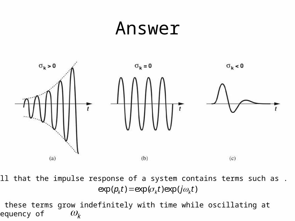
Answer
Recall that the impulse response of a system contains terms such as .
If , these terms grow indefinitely with time while oscillating at a frequency of
exp( ) exp( )exp( )k k kp t t j t
k