Embed Size (px)
Citation preview
SIMAlliance - Interoperability Stepping Stones Release 7 1/192
Interoperability
Stepping Stones Release 7
Version 1.0.0
SIMAlliance - Interoperability Stepping Stones Release 7 2/192
Figure index .......................................................................................................... 9
1 Introduction .................................................................................................. 10
1.1 Acknowledgements........................................................................................... 10
Reference Documentation .................................................................................. 11
2 Abbreviations................................................................................................. 12
3 Definitions ..................................................................................................... 14
4 Release 6: the standard evolution ................................................................ 15 4.1.1 UICC physical/logical characteristics......................................................................................................15 4.1.2 UICC OTA ............................................................................................................................................16 4.1.3 UICC Toolkit.........................................................................................................................................17 4.1.4 UICC JAVA Card ...................................................................................................................................18
5 Release 7: a major breakdown...................................................................... 20
6 The UICC Architecture................................................................................... 21
6.1 Definition of UICC ............................................................................................. 21
6.2 Application selection......................................................................................... 21
6.3 File system........................................................................................................ 22 6.3.1 Security architecture ............................................................................................................................22 6.3.2 Referencing a EFARR record: the Referenced Format...............................................................................22 6.3.3 Structure of the EFARR file......................................................................................................................23
6.4 PIN in the UICC................................................................................................. 24 6.4.1 Security Environments in the UICC .......................................................................................................25 6.4.2 Retrieving information about a file: the FCP template............................................................................25 6.4.3 Files Life Cycle Status...........................................................................................................................27
6.5 Mapped files...................................................................................................... 27
7 Mobile Near Field Communication (Mobile NFC) .......................................... 29
7.1 Scope ................................................................................................................ 29
7.2 NFC Operating Modes ....................................................................................... 29 7.2.1 Card Emulation Mode ...........................................................................................................................29 7.2.2 Reader Mode........................................................................................................................................29 7.2.3 Peer-to-Peer mode ...............................................................................................................................29
7.3 NFC Device Identification ................................................................................. 29
7.4 Overview of Mobile NFC.................................................................................... 29
7.5 Data Transmission Rates .................................................................................. 30
7.6 Communication between NFC-terminal and UICC ............................................ 30
7.7 SWP Stack Overview......................................................................................... 31
7.8 Structure of a SWP Frame and of an HCI packet .............................................. 33
7.9 HCI Message Fragmentation............................................................................. 33
7.10 HCI Hosts, Gates and Pipes............................................................................ 34
7.11 Indication of SWP support ............................................................................. 35 7.11.1 UICC....................................................................................................................................................35 7.11.2 Mobile..................................................................................................................................................35
SIMAlliance - Interoperability Stepping Stones Release 7 3/192
7.12 Applet Developer's Perspective on NFC ......................................................... 35 7.12.1 Current state of Contactless APIs..........................................................................................................35 7.12.2 JavaCard 2.2.2 Contactless API.............................................................................................................36 7.12.3 Considerations on developing applets for contactless systems ...............................................................36 7.12.4 Connectivity mechanism .......................................................................................................................37
7.13 Interworking of UICC interfaces.................................................................... 37 7.13.1 Concurrency.........................................................................................................................................37 7.13.2 Reset Behavior.....................................................................................................................................38
7.14 Support of different NFC Protocols with SWP and HCI .................................. 38
8 Java Card Features ........................................................................................ 39
8.1 Java Card Language: a Subset of Java Language ............................................. 39
8.2 Backward Compatibility .................................................................................... 39
8.3 The Java Card Runtime Environment................................................................ 39 8.3.1 Atomicity and Transactions...................................................................................................................39 8.3.2 Security Concept and Firewalls .............................................................................................................39 8.3.3 Entry Point Objects ..............................................................................................................................41 8.3.4 Global Arrays .......................................................................................................................................41
8.4 The Java Card VM.............................................................................................. 42 8.4.1 Summary of Java Card Language Limitations ........................................................................................42 Summary of Java Card VM Constraints.................................................................................................................42
8.5 Development tools ............................................................................................ 43 8.5.1 Converter.............................................................................................................................................43 8.5.2 Verifier.................................................................................................................................................43
8.6 The Java Card API............................................................................................. 43 java.lang ........................................................................................................................................................43 javacard.framework......................................................................................................................................44 javacard.framework.service .....................................................................................................................45 javacard.security........................................................................................................................................45 javacardx.crypto..........................................................................................................................................46 java.rmi ..........................................................................................................................................................46
8.7 New JC 2.2.2 Features ...................................................................................... 46 8.7.1 Logical Channels ..................................................................................................................................47 8.7.2 External Memory access .......................................................................................................................47 8.7.3 Optional extension framework packages ...............................................................................................47 8.7.4 Additional features ...............................................................................................................................48
8.8 Java Card Remote Method Invocation (JCRMI)................................................ 48 8.8.1 General description ..............................................................................................................................48 8.8.2 Remote Objects ...................................................................................................................................49 8.8.3 Description of the mechanism...............................................................................................................49
8.9 Managing Memory and Objects......................................................................... 51 8.9.1 Garbage collector:................................................................................................................................51
8.10 Java Card Technology Compatibility Kit......................................................... 51
8.11 Overview of Versions needed for basic interoperability................................. 52
9 Card Application Toolkit (CAT) - USIM Application Toolkit (USAT) .............. 53
9.1 Scope ................................................................................................................ 53
9.2 CAT commands ................................................................................................. 53
9.3 What is a CAT session? ..................................................................................... 53
9.4 What is a proactive session?............................................................................. 54
9.5 Multimedia Messages........................................................................................ 54
SIMAlliance - Interoperability Stepping Stones Release 7 4/192
9.6 Terminal Applications ....................................................................................... 54
10 (U)SIM and UICC API description .............................................................. 56
10.1 Scope ............................................................................................................. 56
10.2 Toolkit API and CAT Runtime Environment.................................................... 56 10.2.1 The CAT Runtime Environment.............................................................................................................56 10.2.2 Toolkit Applet.......................................................................................................................................56
10.3 Terminal Profile.............................................................................................. 60
10.4 Envelope management................................................................................... 60 10.4.1 Envelope management .........................................................................................................................60 10.4.2 EnvelopeResponseHandler management for the event EVENT_FORMATTED_SMS_PP_ENV ....................61 10.4.3 EnvelopeResponseHandler management for the events EVENT_CALL_CONTROL_BY_NAA or
EVENT_MO_SHORT_MESSAGE_ CONTROL_BY_NAA_SMS_PP_ENV ......................................................................61 10.4.4 Details .................................................................................................................................................62
10.5 Event management ........................................................................................ 62 10.5.1 Overview .............................................................................................................................................62 10.5.2 List of the available Events ...................................................................................................................63 10.5.3 Events Description................................................................................................................................64
10.6 Proactive Command ....................................................................................... 71 10.6.1 Proactive command management .........................................................................................................71 10.6.2 Details on the Proactive Handler and ProactiveResponse Handler ..........................................................72 10.6.3 System Proactive commands ................................................................................................................73
10.7 File access API and File administration API ................................................... 73 10.7.1 Structure of the File System .................................................................................................................73 10.7.2 The file access API ...............................................................................................................................74 10.7.3 File Administration API .........................................................................................................................76 10.7.4 BER TLV file access API........................................................................................................................77
10.8 Short Messages and their handling with the USIM API ................................. 78 10.8.1 Single SMS-PP......................................................................................................................................78 10.8.2 Concatenated SMS PP ..........................................................................................................................79 10.8.3 TLV structure for Update Record...........................................................................................................81 10.8.4 Methods to retrieve UDL.......................................................................................................................82 10.8.5 Structure of Short Message Cell Broadcast ............................................................................................82 10.8.6 Concatenated SMS-CB..........................................................................................................................83
10.9 An useful resource: the uicc.system package ................................................ 84
10.10 SIM API ....................................................................................................... 84
11 The phonebook ........................................................................................... 85
11.1 Phonebook Principle ...................................................................................... 85
11.2 Structure of the phonebook ........................................................................... 85 11.2.1 The different files used to define a contact ...........................................................................................85 11.2.2 The EFPBR file (Phone Book Reference)..................................................................................................86 11.2.3 The EFIAP file (Index Administration Phonebook)....................................................................................86 11.2.4 The EFPBC file (Phone Book control).......................................................................................................87 11.2.5 The other files......................................................................................................................................87
11.3 An example of phonebook content ................................................................ 87
11.4 Global and local phonebooks ......................................................................... 87
11.5 Link with the GSM SIM phonebook ................................................................ 88
11.6 Phonebook synchronization ........................................................................... 88
12 Interworking between SIM and USIM applications................................... 89
12.1 IMSI, secret key and authentication algorithm ............................................. 89
SIMAlliance - Interoperability Stepping Stones Release 7 5/192
12.2 Secret codes................................................................................................... 89
12.3 Mapping of CHV1............................................................................................ 89
12.4 Mapping of CHV2............................................................................................ 89
12.5 Mapping of Local PINs ................................................................................... 90
12.6 Mapping of administrative PINs..................................................................... 90
12.7 Access condition ............................................................................................ 90
12.8 Access to file system for 2G / 3G applets....................................................... 90 12.8.1 Definitions ...........................................................................................................................................90 12.8.2 Accessibility table .................................................................................................................................90
12.9 Activation of SIM and USIM applications....................................................... 90
12.10 SIM and USIM APIs interworking ............................................................... 90 12.10.1 Terminal Profile ................................................................................................................................91 12.10.2 Triggering and Registration...............................................................................................................91 12.10.3 System handlers and proactive commands ........................................................................................91 12.10.4 Behaviours of SIM API used in a 3G mode.........................................................................................91
12.11 Behaviours of USIM API used in 2G mode .................................................. 91
13 Generic Description About Transport And Security Usage......................... 92 13.1.1 Command Packet .................................................................................................................................92 13.1.2 Response Packet ..................................................................................................................................93 13.1.3 Length coding for CPL, CHL, RPL, RHL ..................................................................................................94
14 Security Parameters Description For Secure Packets ................................ 95
14.1 Coding of the SPI: Security Parameter Indicator........................................... 95 14.1.1 Coding of the KIc field..........................................................................................................................96 14.1.2 Coding of the KID field .........................................................................................................................97
14.2 Toolkit Application Reference ........................................................................ 98
14.3 Counter Field and Management ..................................................................... 98
14.4 PCNTR ............................................................................................................ 99
14.5 Secured Data.................................................................................................. 99
15 Data Download .........................................................................................100
15.1 The Different Transport Protocols For a Data Download ............................. 100 15.1.1 Short Message Point-To-Point .............................................................................................................100 15.1.2 USSD: Unstructured Supplementary Service Data................................................................................107
15.2 Short Message Cell Broadcast ...................................................................... 113 15.2.1 Structure of the CBS page in the SMS-CB Message..............................................................................114 15.2.2 Cell Broadcast Page Parameters..........................................................................................................114 15.2.3 A Command Packet contained in a SMS-CB message...........................................................................115 15.2.4 Multiple Short Message Cell Broadcast Description ..............................................................................115 15.2.5 Structure of the Response Packet for a SMS-CB Message ....................................................................116
16 BIP commands and events ....................................................................... 117
16.1 Introduction to the Bearer Independent Protocol (BIP).............................. 117
16.2 BIP Commands description.......................................................................... 118 16.2.1 OPEN CHANNEL .................................................................................................................................118 16.2.2 OPEN CHANNEL related to Circuit Switched bearer ..............................................................................118 16.2.3 CLOSE CHANNEL................................................................................................................................120 16.2.4 SEND DATA .......................................................................................................................................120 16.2.5 RECEIVE DATA...................................................................................................................................120 16.2.6 GET CHANNEL STATUS ......................................................................................................................121 16.2.7 SERVICE SEARCH...............................................................................................................................121
SIMAlliance - Interoperability Stepping Stones Release 7 6/192
16.2.8 GET SERVICE INFORMATION .............................................................................................................121 16.2.9 DECLARE SERVICE .............................................................................................................................121
16.3 BIP Events description................................................................................. 121 16.3.1 EVENT DOWNLOAD (DATA AVAILABLE):.............................................................................................121 16.3.2 EVENT DOWNLOAD (CHANNEL STATUS) ............................................................................................121 16.3.3 EVENT DOWNLOAD LOCAL CONNECTION...........................................................................................122 16.3.4 Terminal Profile indication for BIP.......................................................................................................123
16.4 Java-API for BIP .......................................................................................... 123
16.5 Reliability and Security using BIP................................................................ 125
16.6 Applet Developer tips................................................................................... 125
17 SCWS......................................................................................................... 126
17.1 Scope ........................................................................................................... 126
17.2 Overview of SCWS........................................................................................ 126
17.3 Specifications............................................................................................... 126
17.4 Architecture of the SCWS solution ............................................................... 127
17.5 SCWS Local Content..................................................................................... 128
17.6 SCWS HTTP commands for local content ..................................................... 128
17.7 Access Control and Security......................................................................... 129
17.8 HTTP Authentication .................................................................................... 129
17.9 Access Control Policy Enforcer ..................................................................... 129
17.10 SCWS remote Administration.................................................................... 130 17.10.1 SCWS administrative commands .....................................................................................................130 17.10.2 The Full Administration Protocol......................................................................................................130 17.10.3 The lightweight protocol .................................................................................................................131
17.11 Servlet Development................................................................................. 131 17.11.1 SCWS API Overview .......................................................................................................................131 17.11.2 Deployment of SCWS Extensions ....................................................................................................132
18 Card Application Toolkit Transport Protocol (CAT_TP)............................ 133
18.1 Scope ........................................................................................................... 133
18.2 Overview of CAT_TP..................................................................................... 133
18.3 CAT_TP Protocol .......................................................................................... 134
18.4 Segmentation Management ......................................................................... 135 18.4.1 Max SDU Size.....................................................................................................................................136 18.4.2 Max PDU Size.....................................................................................................................................136
18.5 Connection Management ............................................................................. 137 18.5.1 CAT_TP Connection Ports ...................................................................................................................137 18.5.2 Identification Data..............................................................................................................................137 18.5.3 Flow Control and Window Management ..............................................................................................137 18.5.4 Retransmission Timer.........................................................................................................................138 18.5.5 Retransmission Counter......................................................................................................................138 18.5.6 CLOSE-WAIT Timer ............................................................................................................................139
18.6 PUSH command............................................................................................ 139 18.6.1 PUSH command “Request for Open Channel”......................................................................................139 18.6.2 PUSH command “Request for CAT_TP link establishment” ...................................................................140 18.6.3 Response to the PUSH SMS ................................................................................................................140
19 Card Remote Management ....................................................................... 142
SIMAlliance - Interoperability Stepping Stones Release 7 7/192
19.1 Remote Management Application data formats........................................... 142 19.1.1 Compact Remote Management Application data format.......................................................................142 19.1.2 Compact Remote response structure...................................................................................................142 19.1.3 Expanded Remote Management Application data format .....................................................................142 19.1.4 Expanded Remote Commands ............................................................................................................142 19.1.5 Expanded Remote Responses .............................................................................................................146
‘03’ Unable to process script chaining (e.g. no resources to store chaining context)............................................................................................................. 149
20 Remote File Management Architecture.................................................... 149
20.1 Remote File Access for UICC ........................................................................ 149
20.2 Remote File Access for ADF.......................................................................... 149
20.3 RFM and expanded format using script chaining TLV command.................. 150
20.4 Remote File Application Parameters ............................................................ 150
20.5 Remote File Management AID and TAR ....................................................... 151 20.5.1 RFM Commands .................................................................................................................................151
21 Remote Application Management ............................................................ 153
21.1 Remote Application Management Architecture............................................ 153 21.1.1 Application Loading and Installation Process .......................................................................................153 21.1.2 Application Life Cycle States ...............................................................................................................154
21.2 Description of the IN/OUT Commands......................................................... 154 21.2.1 LOAD Command.................................................................................................................................154 21.2.2 INSTALL (load) Command ..................................................................................................................154 21.2.3 INSTALL(Install) Command ................................................................................................................154 21.2.4 DELETE Command .............................................................................................................................161 21.2.5 GET DATA command..........................................................................................................................162 21.2.6 GET STATUS command ......................................................................................................................162 21.2.7 PUT KEY command ............................................................................................................................162
22 Security domain and Key Management.................................................... 163
22.1 Security Domains on UICC Java Cards ......................................................... 163 22.1.1 Introduction .......................................................................................................................................163 22.1.2 Security Domains in non-OTA communication .....................................................................................163
22.2 Security Domains in OTA-communication.................................................... 164 22.2.1 Key Management ...............................................................................................................................164 22.2.2 Set Up of Security Domains ................................................................................................................165 22.2.3 Interoperability regarding Security Domains and GP security ...............................................................165
22.3 Key Management ......................................................................................... 165 22.3.1 Algorithm...........................................................................................................................................165 22.3.2 Key Set Version..................................................................................................................................166
A AID and TARs (annex) .............................................................................. 167
A.1 AID Format ..................................................................................................... 167
A.2 Registered application provider IDentifier (RID) ........................................... 168
A.3 Proprietary application Identifier eXtension (PIX)......................................... 168
A.4 PIX Coding for different Applications ............................................................. 169
A.5 Toolkit Application Reference (TAR)............................................................... 170
A.6 Telecom API Package Version Management ................................................... 171
A.7 SIM API package version management .......................................................... 171
SIMAlliance - Interoperability Stepping Stones Release 7 8/192
A.8 UICC API package version management ........................................................ 171
A.9 USIM API for Java Cards package version management ................................ 172
A.10 Java Card API Packages............................................................................... 172
B TLV Coding (annex) .................................................................................. 173
B.1 Tag coding.................................................................................................... 173
B.2 BER-TLVs...................................................................................................... 174
B.3 COMPACT-TLVs ............................................................................................ 174
B.4 COMPREHENSION-TLVs ............................................................................... 174
B.5 Length coding .............................................................................................. 175
B.6 Value coding ................................................................................................ 175
C Administrative Commands (annex).......................................................... 176
C.1 CREATE FILE ................................................................................................... 176
C.2 DELETE FILE.................................................................................................... 177
C.3 RESIZE FILE .................................................................................................... 178
D Interoperable formats for Java Card packages (Annex).......................... 180
D.1 Introduction................................................................................................. 180
D.2 Definition of the CAP file format .................................................................. 180
D.3 Definition of the IJC format ......................................................................... 180
E Examples of Release 6 Toolkit Applets (annex).......................................... 181
E.1 Menu Resizer .................................................................................................. 181
E.2 Phone book monitor........................................................................................ 186
SIMAlliance - Interoperability Stepping Stones Release 7 9/192
Figure index
Figure 1 - The UICC Architecture.................................................................................................................................21 Figure 2 - NFC system architecture..............................................................................................................................30 Figure 3 - The JCRE Context........................................................................................................................................40 Figure 4 - Converting a CAP file...................................................................................................................................43 Figure 5 - RMI communications ...................................................................................................................................49 Figure 6 - File system structure in the UICC.................................................................................................................74 Figure 7 - The USAT Envelope Handler content in case of Formatted SM ......................................................................81 Figure 8 - USAT Envelope Handler in case of formatted CB ..........................................................................................83 Figure 9 - USAT Envelope Handler in case of unformatted CB.......................................................................................84 Figure 10 - A good example of a Phonebook................................................................................................................87 Figure 11 - Formatted SM structure...........................................................................................................................101 Figure 12 - The UDH in an SM-PP..............................................................................................................................101 Figure 13 - The UDH structure ..................................................................................................................................103 Figure 14 - Response packet structure.......................................................................................................................105 Figure 15 - The User Data Header in C-SM PP............................................................................................................106 Figure 16 - The CBS pages ........................................................................................................................................114 Figure 17 - CBS structure with Secured Data .............................................................................................................116 Figure 18 - BIP Protocol stack ...................................................................................................................................117 Figure 19 - Overview CAT_TP protocol layer with associated layers in OTA platform, UE & UICC environment .............134 Figure 20 - Illustration Data Exchange in PUSH mode ................................................................................................135 Figure 21 - CAT_TP Segmentation mechanism including ETSI TS 102 225 Security .....................................................136 Figure 22 - Window in CAT_TP Flow Control ..............................................................................................................138 Figure 23 - Expanded Remote Format .......................................................................................................................143 Figure 24 - Format of a Command Session TLV..........................................................................................................143 Figure 25 - The ways of accessing an ADF.................................................................................................................150 Figure 26 - Remote Application Management Architecture..........................................................................................153 Figure 27 - Loading and installing an application........................................................................................................154 Figure 28 - SAT and USAT toolkit install parameters...................................................................................................156 Figure 29 - Security Domains in non-OTA communications.........................................................................................164 Figure 30 - Structure of an AID .................................................................................................................................168
SIMAlliance - Interoperability Stepping Stones Release 7 10/192
1 Introduction
In today's telecom environment, innovative services must be launched not only within the shortest timeframe, but also with greater flexibility for future upgrades and easy service maintenance. During the years, Java Card has proved itself
as the key technology in service deployment. The Java Card™ 2.1 standard was released by the Java Card Forum in early 1999. At the same time, ETSI endorsed the use of Java Card™ in SIM cards and defined the GSM SIM API for Java Cards. Since them, Java Card technology and ETSI specifications have been continuously evolving to face new services and new potentiality, up to the 3G telecommunication world, finalized in the Release 7 of ETSI specifications and in Java Card 2.2.1.
At the same times, interoperability between smart cards improved due to the field experience and also due to the Interoperability Stepping Stones, intended to address and solve all different interpretations of the specifications that could lead to different implementations. Completing ETSI's work of releasing specifications and test suites, the purpose of this guide is to provide developers with information concerning Java Card™ SIM constraints and a common interpretation of the standards for the members of
the SIM Alliance that contributed to this document.
The target audience of this guide is Network Operators, Wireless Service Providers and anyone interested in interoperable Java Card applet development.
Used in conjunction with the Java Card Applet Developer's Guide from SUN Microsystems, this guide aims to allow
interoperable Java Card applications to be developed, thereby providing:
• Interoperable behaviors of the Java Cards
• A common implementation of the standard APIs This was achieved following a detailed gap analysis of all the Java Cards on the market, the result of which clarify and explain the following standards:
• Java Card (JCRE, API)
• Toolkit APIs
• Toolkit security • Remote Management (Application Loading, File Management)
1.1 Acknowledgements The document has been edited and maintained in the years by the SIM Alliance Java Card Interoperability WG. A lot of people have been contributing the document for years, but a special thank goes to the people active in the JIWG or that have been very active in the past, including: Cecile Assiet Le Doujet, Franck Barbet, Laurence Bringer, Pierre Fargues, Virginie Galindo, Guillaume Nave, Hung Ju Wang (Gemalto), Carsten Fischer, Thomas John, Wladimir Pauls, Jens Siebert, Detlef Kohelers (Sagem Orga), Khalid Hadj, Thierry Simon, Sebastian Sohier, Mehdi Soumhi (Oberthur), Giancarlo Celentano, Amedeo Veneroso (ST Incard),
Daniel Daksiewicz, Dr. Stephan Miculcy, Ulrich Huber, Michael Schnellinger, Thorsten Urhahn, Nils Nitsch (G&D).
SIMAlliance - Interoperability Stepping Stones Release 7 11/192
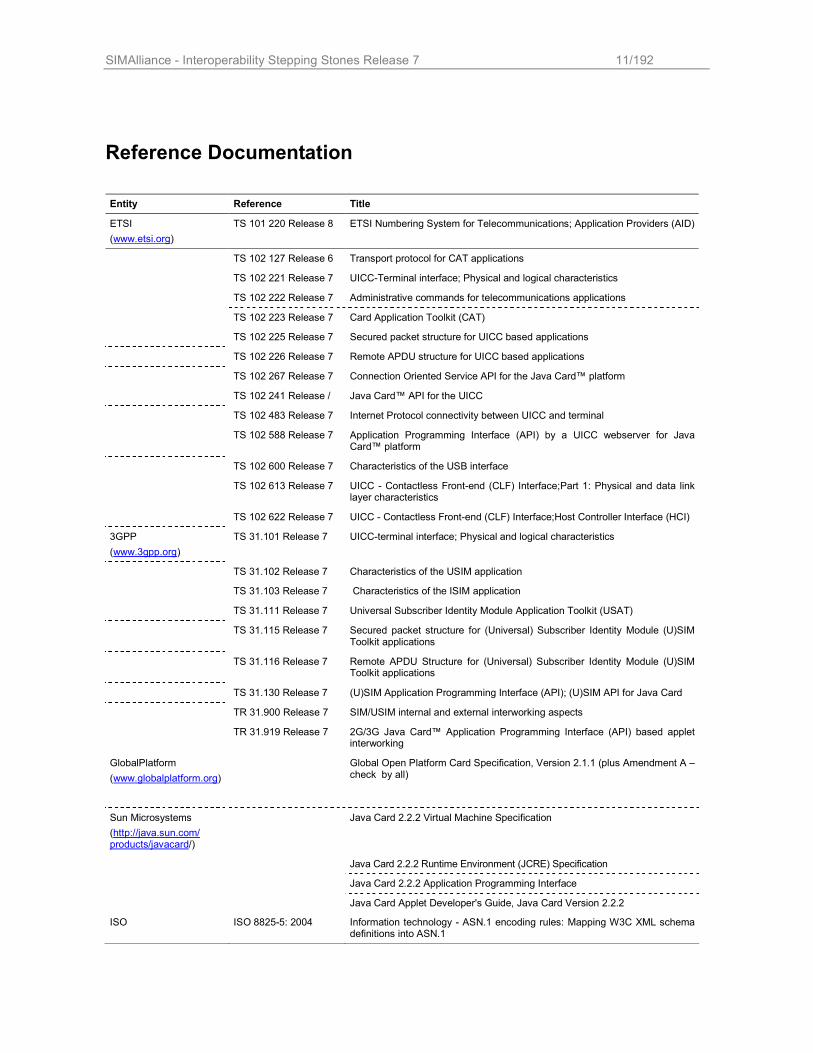
Reference Documentation
Entity Reference Title
ETSI
(www.etsi.org)
TS 101 220 Release 8 ETSI Numbering System for Telecommunications; Application Providers (AID)
TS 102 127 Release 6 Transport protocol for CAT applications
TS 102 221 Release 7 UICC-Terminal interface; Physical and logical characteristics
TS 102 222 Release 7 Administrative commands for telecommunications applications
TS 102 223 Release 7 Card Application Toolkit (CAT)
TS 102 225 Release 7 Secured packet structure for UICC based applications
TS 102 226 Release 7 Remote APDU structure for UICC based applications
TS 102 267 Release 7 Connection Oriented Service API for the Java Card™ platform
TS 102 241 Release / Java Card™ API for the UICC
TS 102 483 Release 7 Internet Protocol connectivity between UICC and terminal
TS 102 588 Release 7 Application Programming Interface (API) by a UICC webserver for Java Card™ platform
TS 102 600 Release 7 Characteristics of the USB interface
TS 102 613 Release 7 UICC - Contactless Front-end (CLF) Interface;Part 1: Physical and data link layer characteristics
TS 102 622 Release 7 UICC - Contactless Front-end (CLF) Interface;Host Controller Interface (HCI)
3GPP
(www.3gpp.org)
TS 31.101 Release 7 UICC-terminal interface; Physical and logical characteristics
TS 31.102 Release 7 Characteristics of the USIM application
TS 31.103 Release 7 Characteristics of the ISIM application
TS 31.111 Release 7 Universal Subscriber Identity Module Application Toolkit (USAT)
TS 31.115 Release 7 Secured packet structure for (Universal) Subscriber Identity Module (U)SIM Toolkit applications
TS 31.116 Release 7 Remote APDU Structure for (Universal) Subscriber Identity Module (U)SIM Toolkit applications
TS 31.130 Release 7 (U)SIM Application Programming Interface (API); (U)SIM API for Java Card
TR 31.900 Release 7 SIM/USIM internal and external interworking aspects
TR 31.919 Release 7 2G/3G Java Card™ Application Programming Interface (API) based applet interworking
GlobalPlatform
(www.globalplatform.org)
Global Open Platform Card Specification, Version 2.1.1 (plus Amendment A – check by all)
Sun Microsystems
(http://java.sun.com/ products/javacard/)
Java Card 2.2.2 Virtual Machine Specification
Java Card 2.2.2 Runtime Environment (JCRE) Specification
Java Card 2.2.2 Application Programming Interface
Java Card Applet Developer's Guide, Java Card Version 2.2.2
ISO ISO 8825-5: 2004 Information technology - ASN.1 encoding rules: Mapping W3C XML schema definitions into ASN.1
SIMAlliance - Interoperability Stepping Stones Release 7 12/192
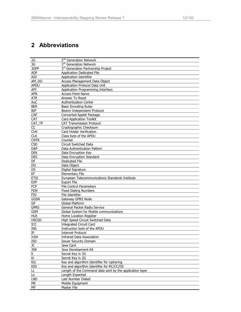
2 Abbreviations
2G 2nd Generation Network
3G 3rd Generation Network
3GPP 3rd Generation Partnership Project
ADF Application Dedicated File
AID Application Identifier
AM_DO Access Management Data Object
APDU Application Protocol Data Unit
API Application Programming Interface
APN Access Point Name
ATR Answer To Reset
AuC Authentication Center
BER Basic Encoding Rules
BIP Bearer Independent Protocol
CAP Converted Applet Package
CAT Card Application Toolkit
CAT_TP CAT Transmission Protocol
CC Cryptographic Checksum
CHV Card Holder Verification
CLA Class byte of the APDU
CNTR Counter
CSD Circuit Switched Data
DAP Data Authentication Pattern
DEK Data Encryption Key
DES Data Encryption Standard
DF Dedicated File
DO Data Object
DS Digital Signature
EF Elementary File
ETSI European Telecommunications Standards Institute
EXP Export File
FCP File Control Parameters
FDN Fixed Dialing Numbers
FID File Identifier
GGSN Gateway GPRS Node
GP Global Platform
GPRS General Packet Radio Service
GSM Global System for Mobile communications
HLR Home Location Register
HSCSD High Speed Circuit Switched Data
ICC Integrated Circuit Card
INS Instruction byte of the APDU
IP Internet Protocol
IrDA Infrared Data Association
ISD Issuer Security Domain
JC Java Card
JDK Java Development Kit
K Secret Key in 3G
Ki Secret Key in 2G
KIc Key and algorithm Identifier for ciphering
KID Key and algorithm Identifier for RC/CC/DS
Lc Length of the Command data sent by the application layer
Le Length Expected
LND Last Number Dialed
ME Mobile Equipment
MF Master File
SIMAlliance - Interoperability Stepping Stones Release 7 13/192
MSISDN Mobile Station International ISDN Number
MSL Minimum Security Level
NAA Network Access Application
OPEN Global Platform Environment
OTA Over The Air
P1 Parameter byte 1 of the APDU
P2 Parameter byte 2 of the APDU
P3 Parameter byte 3 of the APDU
PCNTR Padding Counter
PDP Packet Data Protocol
PFI Packet Format Information
PIN Personal Identification Number
PIX Proprietary application Identifier eXtension (part of the AID)
PoR Proof of Receipt
RAM Remote Applet Management
RC Redundancy Checksum
RE Receiving Entity
RFM Remote File Management
RID Registered application provider IDentifier (part of the AID)
RMI Remote Method Invocation
RS232 Recommended Standard 232
RTE Runtime Environment
SAT Sim Application Toolkit
SC_DO Security Condition Data Object
SCWS Smart Card Web Server
SCP Smart Card Platform
SD Security Domain
SE Security Environment or
Sending Entity (OTA)
SGSN Serving GPRS Node
SIM Subscriber Identity Module
SMS Short Message Service
SPI Security Parameter Indicator
SW Status Word
TAR Toolkit Application Reference
TCK Test Compatibility Kit
TCP Transmission Control Protocol
TLV Tag Length Value
TS Technical Specification
UDP User Datagram Protocol
UICC Universal Integrated Circuit Card
UMTS Universal Mobile Telecommunication System
USAT USim Application Toolkit
USB Universal Serial Bus
USIM Universal Subscriber Identity Module
UTRAN UMTS Terrestrial Radio Access Network
SIMAlliance - Interoperability Stepping Stones Release 7 14/192
3 Definitions
Global Platform API The GlobalPlatform API provides services to Applications (e.g. cardholder verification, personalization, or security services).
Integrated Circuit Card The most general term for a smart card is “ICC”. It is always a physical and logical entity either a SIM or a UICC.
Issuer Security Domain The representative entity of the card issuer. It provides support for control, security and communication requirements of the card issuer.
Over-The-Air Technology which uses the mobile network features to download data to the UICC.
Remote Application Management
Remote Application Management applications are OTA interfaces to the Issuer Security Domain and other Security Domains.
Smart Card Web Server A standard HTTP 1.1 web server embedded in a card allowing the communication with a HTTP client on the handset e.g. a web browser.
Security Domain A special application that supports a secure communication between an Application Provider’s application and off-card entities during its personalization phase and runtime.
Subscriber Identity Module “SIM” is the term that defines the ICC for a 2G card, there is no distinction between the physical and logical entity and the application itself. In a UICC, the “SIM” is an application. If it is active, the UICC is functionally identical to a 2G card.
Toolkit Application Reference
Unique identification for Toolkit applications when using Over-The-Air functionality.
Universal Integrated Circuit
Card
The UICC is the physical and logical platform for the USIM. It can, at least, contain
one USIM application and may additionally embed a SIM application.
Universal Subscriber
Identity Module
The USIM is not a physical entity. It is a purely logical application on a UICC. It
does only accept 3G commands and therefore it is not compatible with a 2G ME. The USIM may provide mechanisms to support 2G authentication and key
agreement to allow a 3G ME to access to a 2G network. (see 3GPP TS 31 102)
SIMAlliance - Interoperability Stepping Stones Release 7 15/192
4 Release 6: the standard evolution
The Release 6 introduces a new set of standards for File System, Over The Air remote management, Toolkit feature and
associated APIs. The following chapter lists the document specifications in order to help the reader in understanding the relationships between them. Historical evolution of the standard is also described to show the path from previous Release specifications to Release 6 specifications.
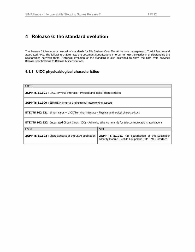
4.1.1 UICC physical/logical characteristics
UICC
3GPP TS 31.101 : UICC-terminal interface - Physical and logical characteristics
3GPP TS 31.900 : SIM/USIM internal and external interworking aspects
ETSI TS 102 221 : Smart cards – UICC/Terminal interface - Physical and logical characteristics
ETSI TS 102 222 : Integrated Circuit Cards (ICC) - Administrative commands for telecommunications applications
USIM SIM
3GPP TS 31.102 : Characteristics of the USIM application
3GPP TS 51.011 R5: Specification of the Subscriber
Identity Module - Mobile Equipment (SIM - ME) Interface
SIMAlliance - Interoperability Stepping Stones Release 7 16/192
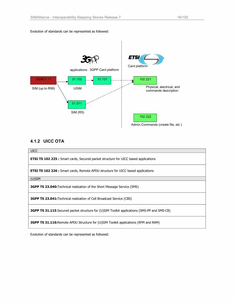
Evolution of standards can be represented as followed:
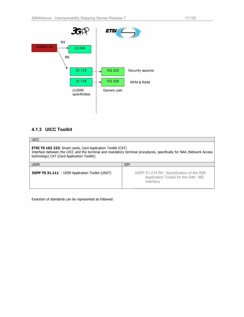
4.1.2 UICC OTA
UICC
ETSI TS 102 225 : Smart cards, Secured packet structure for UICC based applications
ETSI TS 102 226 : Smart cards, Remote APDU structure for UICC based applications
(U)SIM
3GPP TS 23.040:Technical realization of the Short Message Service (SMS)
3GPP TS 23.041:Technical realization of Cell Broadcast Service (CBS)
3GPP TS 31.115:Secured packet structure for (U)SIM Toolkit applications (SMS-PP and SMS-CB)
3GPP TS 31.116:Remote APDU Structure for (U)SIM Toolkit applications (RFM and RAM)
Evolution of standards can be represented as followed:
GSM11.11 31.101 31.102
51.011
102 221
Physical, electrical, and commands description
applications
SIM (R5)
102 222
Admin.Commands (create file, etc )
3GPP Card platform
USIM
Card platform
SIM (up to R99)
SIMAlliance - Interoperability Stepping Stones Release 7 17/192
GSM03.48
31.115
31.116
102 225 Security aspects
RFM & RAM
23.048
R5
R6
102 226
(U)SIM specificities
Generic part
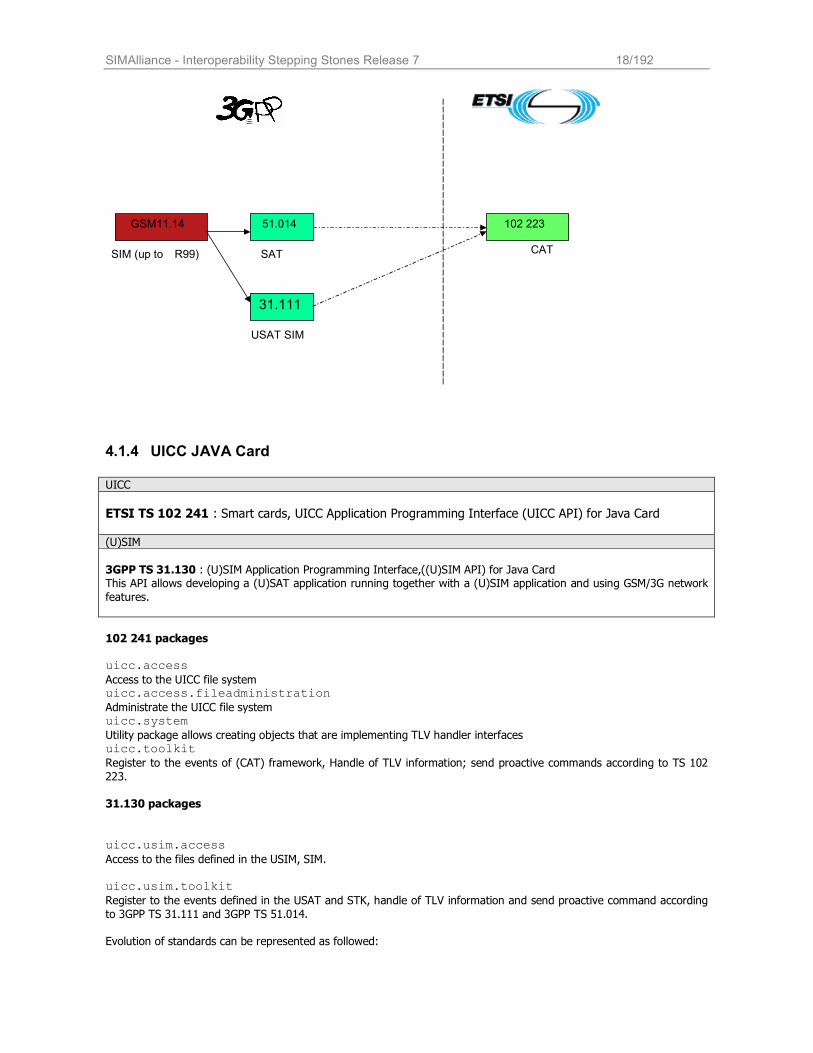
4.1.3 UICC Toolkit
UICC
ETSI TS 102 223: Smart cards, Card Application Toolkit (CAT) Interface between the UICC and the terminal and mandatory terminal procedures, specifically for NAA (Network Access
technology) CAT (Card Application Toolkit).
USIM SIM
3GPP TS 31.111 : USIM Application Toolkit (USAT)
3GPP 51.014 R5 : Specification of the SIM Application Toolkit for the SIM - ME interface
Evolution of standards can be represented as followed:
SIMAlliance - Interoperability Stepping Stones Release 7 18/192
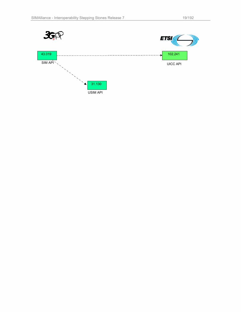
4.1.4 UICC JAVA Card
UICC
ETSI TS 102 241 : Smart cards, UICC Application Programming Interface (UICC API) for Java Card
(U)SIM
3GPP TS 31.130 : (U)SIM Application Programming Interface,((U)SIM API) for Java Card This API allows developing a (U)SAT application running together with a (U)SIM application and using GSM/3G network
features.
102 241 packages uicc.access Access to the UICC file system uicc.access.fileadministration Administrate the UICC file system uicc.system Utility package allows creating objects that are implementing TLV handler interfaces uicc.toolkit Register to the events of (CAT) framework, Handle of TLV information; send proactive commands according to TS 102
223.
31.130 packages
uicc.usim.access Access to the files defined in the USIM, SIM. uicc.usim.toolkit Register to the events defined in the USAT and STK, handle of TLV information and send proactive command according
to 3GPP TS 31.111 and 3GPP TS 51.014.
Evolution of standards can be represented as followed:
GSM11.14 51.014
31.111
102 223
CAT
USAT SIM
SAT SIM (up to R99)
SIMAlliance - Interoperability Stepping Stones Release 7 19/192
43.019 102.241
UICC API SIM API
31.130
USIM API
SIMAlliance - Interoperability Stepping Stones Release 7 20/192
5 Release 7: a major breakdown
Even more than the Release 6, the Release 7 has been a major breakdown in expanding card capabilities. With an high focus on new interfaces and new potentiality, standardization fora and smart card industry has defined new paradigms
for card communication and user interaction. Smart Card Web Server (§ 17) enables new user experience and new application model leading the UICC in the well known HTTP-based architecture; SWP and HCI (§ 7) allow the UICC to be a key element of the NFC ecosystem; USB speeds up data communication between card and handset and IP connectivity brings the card in the open IP based network. Being each technology an enabler of new services both independently and jointly with the other technologies, it is expected that several card configuration will not support all the features of Release 7; so it is expected that, depending
on operator needs, some Release 7 card will support SCWS but not NFC, or NFC but not USB or all the technologies together.
SIMAlliance - Interoperability Stepping Stones Release 7 21/192
6 The UICC Architecture
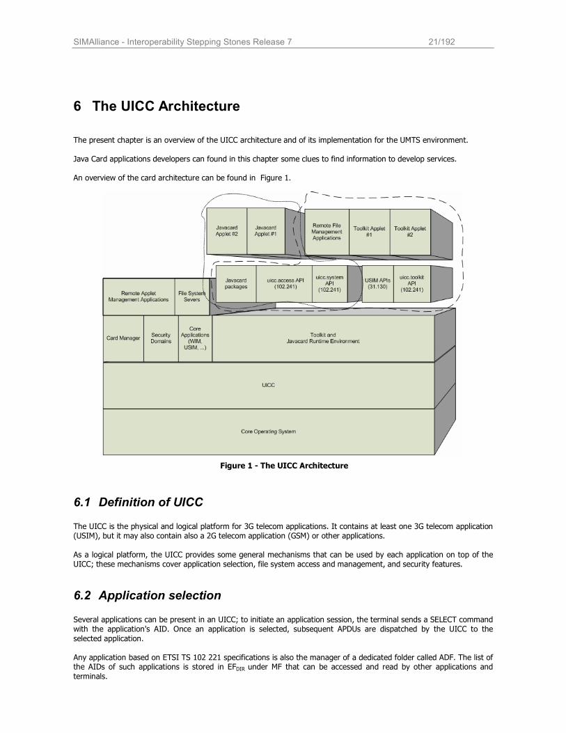
The present chapter is an overview of the UICC architecture and of its implementation for the UMTS environment.
Java Card applications developers can found in this chapter some clues to find information to develop services. An overview of the card architecture can be found in Figure 1.
Figure 1 - The UICC Architecture
6.1 Definition of UICC
The UICC is the physical and logical platform for 3G telecom applications. It contains at least one 3G telecom application (USIM), but it may also contain also a 2G telecom application (GSM) or other applications. As a logical platform, the UICC provides some general mechanisms that can be used by each application on top of the UICC; these mechanisms cover application selection, file system access and management, and security features.
6.2 Application selection Several applications can be present in an UICC; to initiate an application session, the terminal sends a SELECT command with the application's AID. Once an application is selected, subsequent APDUs are dispatched by the UICC to the
selected application.
Any application based on ETSI TS 102 221 specifications is also the manager of a dedicated folder called ADF. The list of the AIDs of such applications is stored in EFDIR under MF that can be accessed and read by other applications and
terminals.
SIMAlliance - Interoperability Stepping Stones Release 7 22/192
To have more applications selected on the UICC at the same time, the mechanism of the Logical Channels is present. On each Logical Channel a different application can be selected; moreover, files can be selected on each Logical Channel
(see ISO/IEC 7816-4). This allows concurrent accesses to different files and also concurrent accesses to the same file.
6.3 File system In the UICC, several kinds of file can be present:
• Dedicated File (DF) that allows functional grouping of files. They can be the parents of DFs and/or EFs. DFs are referenced by file identifiers.
• Application DF (ADF) is a particular DF that contains all the DFs and EFs of an application. ADF are referenced by a DF Name (or AID)
• Elementary File (EF), that contain data and no other files; they can be Transparent, Linear Record, Cyclic Record or BER-TLV structured as defined in ETSI TS 102 221
Elementary Files can be addressed by File Identifier (FID), a two-bytes ID, or by Short File Identifier (SFI). The SFI can be used in file system access APDUs to implicitly select the file without sending an explicit SELECT FILE APDU.
6.3.1 Security architecture
The security architecture in the UICC consists of the following parts:
• Security attributes: a set of access rules; they are attached to an ADF/DF/EF and they are part of the FCP
(see § 6.4.2). • Access rules: consist of an access mode and one or more security conditions.
• Access Mode (AM): indicates to which operations (commands) the security condition applies; they are coded in Access Mode Data Objects (AM_DOs).
• Security Condition (SC): contains references to the applicable key references (PINs); they are coded in Security Conditions Data Objects (SC_DOs).
Each operation applicable to a file (except its selection) is protected by one or more Security Conditions, identifying the prerequisites of the operation. The UICC checks, in order to allow a file operation, the Security Condition related to the relevant Access Mode to verify if the security related procedures (e.g. user PIN verification) are satisfied. The default security condition associated to an operation is NEVER. This means that the security condition for an
operation whose SC_DO object can not be found is set to NEVER.
The Security Attributes can be specified, for each file, in several formats: • Compact format
• Expanded format
• Access rule referencing The different formats have different limitations: the Compact Format is less flexible than the Expanded format, and the Expanded format is less flexible than the Access Rules Referencing format. Though in the UICC there are three different ways to code security attributes, in the USIM all Security Attributes are coded in Access Rules Referencing format (EFARR) according to 3GPP TS 31.102; as a consequence, we consider
Compact format and Expanded format out of the scope of the present document.
6.3.2 Referencing a EFARR record: the Referenced Format
The referenced format is indicated in the FCP following tag '8B'. The access rule is stored in a file, EFARR. This file is a linear fixed file. Referencing is based on the following two methods:
• File ID and record number (File ID, record number); • File ID, SE ID and record number (File ID, SE ID, record number).
The second possibility allows the usage of different access rules in different security environments as defined in the following. When referencing EFARR is based on the file ID, the rules for the location of the access rules are as follows:
SIMAlliance - Interoperability Stepping Stones Release 7 23/192
• for an EF, if the EFARR file with the file ID indicated in tag '8B' cannot be found in the current DF, the parent
DF shall be searched for EFARR. This process shall continue until the EFARR is found or until an ADF or the MF is reached;
• for a DF, if the EFARR file with the file ID indicated in tag '8B' cannot be found in the parent DF, the grandparent DF shall be searched for EFARR. This process shall continue until the EFARR is found or until an
ADF or the MF is reached; for the MF or an ADF, the EFARR file with the file ID indicated in tag '8B' shall be searched under the MF.
The structure of the access rule referencing DO is as follows.
Tag Length Value
'8B' '03' File ID, record number
'8B' '02' + n x '02' File ID, SE IDn1, Record number X, SE IDn2, Record number Y, etc.
6.3.3 Structure of the EFARR file
The structure of the EFARR file is as follows.
Record Number (ARR) Record Content (Access Rule)
'01' AM_DOSC_DO1SC_DO2AM_DOSC_DO3SC_DO4 ….
'02' AM_DOSC_DO1AM_DOSC_DO5SC_DO6 ….
… …
6.3.3.1 AM_DO coding
The AM data objects are coded in different formats depending on the operation to be protected.
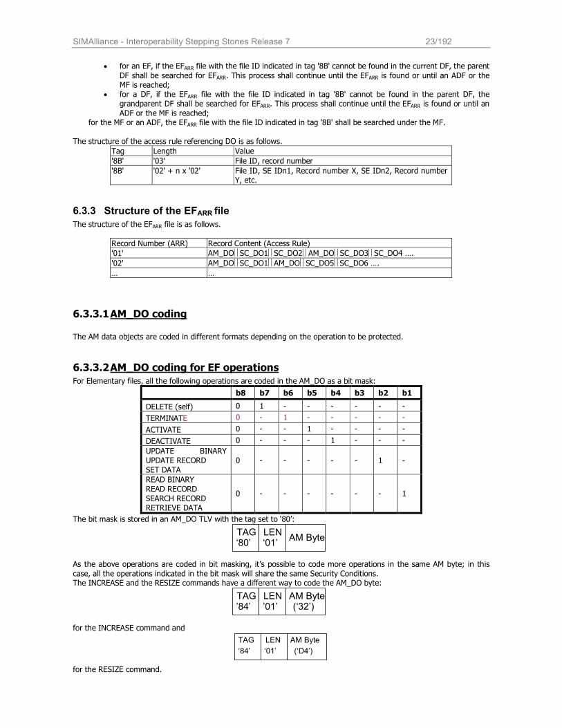
6.3.3.2 AM_DO coding for EF operations
For Elementary files, all the following operations are coded in the AM_DO as a bit mask:
b8 b7 b6 b5 b4 b3 b2 b1
DELETE (self) 0 1 - - - - - -
TERMINATE 0 - 1 - - - - -
ACTIVATE 0 - - 1 - - - -
DEACTIVATE 0 - - - 1 - - -
UPDATE BINARY UPDATE RECORD
SET DATA
0 - - - - - 1 -
READ BINARY READ RECORD
SEARCH RECORD RETRIEVE DATA
0 - - - - - - 1
The bit mask is stored in an AM_DO TLV with the tag set to ‘80’:
As the above operations are coded in bit masking, it’s possible to code more operations in the same AM byte; in this
case, all the operations indicated in the bit mask will share the same Security Conditions. The INCREASE and the RESIZE commands have a different way to code the AM_DO byte:
for the INCREASE command and
for the RESIZE command.
TAG
‘80’ LEN ‘01’
AM Byte
TAG
’84’ LEN ’01’
AM Byte (‘32’)
TAG
‘84’
LEN
‘01’
AM Byte
(‘D4’)
SIMAlliance - Interoperability Stepping Stones Release 7 24/192
Only the INCREASE command or the RESIZE command can be stored in the TLV; so it’s not possible to code more
operations in this AM_DO TLV.
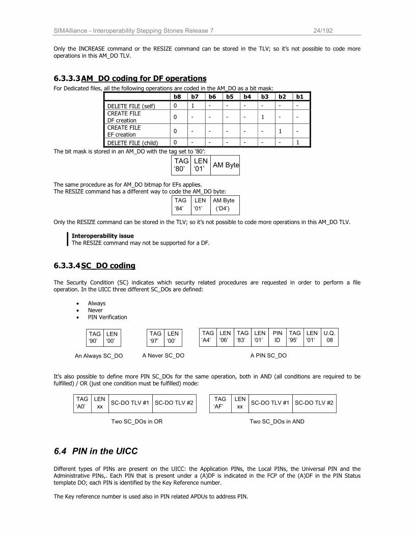
6.3.3.3 AM_DO coding for DF operations
For Dedicated files, all the following operations are coded in the AM_DO as a bit mask:
b8 b7 b6 b5 b4 b3 b2 b1
DELETE FILE (self) 0 1 - - - - - -
CREATE FILE DF creation
0 - - - - 1 - -
CREATE FILE EF creation
0 - - - - - 1 -
DELETE FILE (child) 0 - - - - - - 1
The bit mask is stored in an AM_DO with the tag set to ‘80’:
The same procedure as for AM_DO bitmap for EFs applies. The RESIZE command has a different way to code the AM_DO byte:
Only the RESIZE command can be stored in the TLV; so it’s not possible to code more operations in this AM_DO TLV.
Interoperability issue
The RESIZE command may not be supported for a DF.
6.3.3.4 SC_DO coding
The Security Condition (SC) indicates which security related procedures are requested in order to perform a file operation. In the UICC three different SC_DOs are defined:
• Always • Never • PIN Verification
It’s also possible to define more PIN SC_DOs for the same operation, both in AND (all conditions are required to be fulfilled) / OR (just one condition must be fulfilled) mode:
6.4 PIN in the UICC
Different types of PINs are present on the UICC: the Application PINs, the Local PINs, the Universal PIN and the Administrative PINs,. Each PIN that is present under a (A)DF is indicated in the FCP of the (A)DF in the PIN Status
template DO; each PIN is identified by the Key Reference number.
The Key reference number is used also in PIN related APDUs to address PIN.
TAG
‘80’ LEN ‘01’
AM Byte
TAG
‘84’
LEN
‘01’
AM Byte
(‘D4’)
TAG ‘90’
LEN ‘00’
TAG
‘97’
LEN
‘00’
An Always SC_DO A Never SC_DO A PIN SC_DO
TAG ‘A4’
LEN ‘06’
TAG ‘83’
LEN ‘01’
PIN ID
TAG ‘95’
LEN ‘01’
U.Q. 08
TAG
‘A0’
LEN
xx
Two SC_DOs in OR
SC-DO TLV #1 SC-DO TLV #2 TAG
‘AF’
LEN
xx
Two SC_DOs in AND
SC-DO TLV #1 SC-DO TLV #2
SIMAlliance - Interoperability Stepping Stones Release 7 25/192
Application PIN An application PIN is a PIN that allows access to any file on the UICC where it is referenced in the access rules. It is
uniquely identified by the Key Reference number that is in the set ‘01’ – ’08’ Local PIN A local PIN is a PIN that uses a local key reference which is only valid within the ADF/DF where it is indicated in the FCP. Key reference numbers for Local PIN are in the set ‘81’ – ’88’; two different ADFs can use the same local key reference
number with different PIN value and different status (enabled, disabled, verified, blocked), one for each ADF.
Universal PIN The Universal PIN is a PIN that is used in a multi-application environment to allow several applications to share one
common PIN. The Universal PIN is a global access condition that has been assigned a key reference value '11'. Administrative PIN Up to 10 administrative PINs may be available. They are usually dedicated to the operator. They are uniquely identified by the Key Reference number that is in the global set ’0A’ – ’0E’ and the local set ‘8A’ – ’8E’.
Interoperable issue: It's not guaranteed by all SIM Alliance members that the Local PIN may be defined under DFs that are different from the ADF; usage of local PIN defined under the ADF is guaranteed.
Interoperability Issue SIM Alliance Members can not guarantee that the uses of the administrative PINs are fully interoperable especially concerning the range 0x8A – 0x8E.
6.4.1 Security Environments in the UICC
The Security Environment (SE) is a mechanism to specify, for the card system, the security functions that are available to provide protection to commands for a specific application of the card. As the security functions in the UICC concern PIN verification, the changing of PIN status can affect the currently active security environment. In multi-application UICC with Universal PIN, two different Security Environments are defined depending on Application PIN status; each Application PIN can be in one of the following status:
• The Application PIN is enabled. In this case, each operation protected by the Application PIN still requires
the PIN verification to be allowed. • The Application PIN is disabled. In this case, card behavior depends on the usage qualifier specified for
the Application PIN. This can be: o “Use Universal PIN” (Usage qualifier set to ’08’). In this case, the operations protected by
Application PIN are considered as protected by the Universal PIN: it’s required to verify the Universal PIN to allow such operations.
o “Do not use Universal PIN” (Usage qualifier set to ‘00’). In this case, the operations remain protected by the Application PIN, that is disabled (this allows the operations).
The current SE depends on the state of the Application PIN of the current application; if the Application PIN of the current application is disabled with Usage Qualifier set to “Use Universal PIN”, the current SE is the SE 00; in the other cases, the current SE is the SE 01.
Developer tip: Toolkit applet access conditions consider the active Security Environment as the SE 01; they do not care Universal PIN.
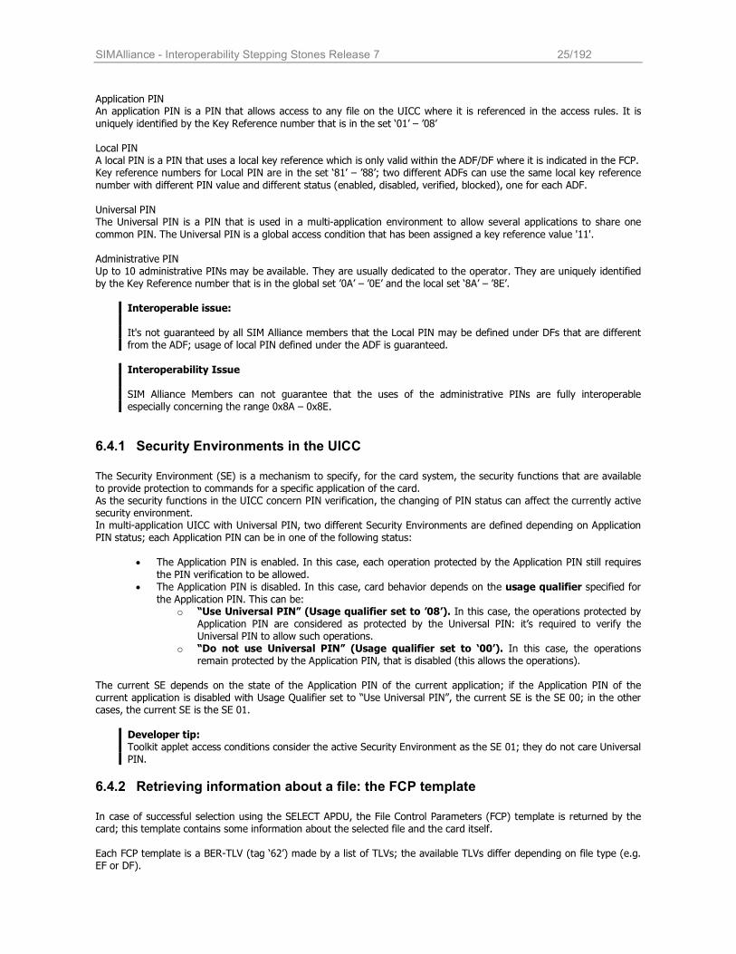
6.4.2 Retrieving information about a file: the FCP template
In case of successful selection using the SELECT APDU, the File Control Parameters (FCP) template is returned by the card; this template contains some information about the selected file and the card itself. Each FCP template is a BER-TLV (tag ‘62’) made by a list of TLVs; the available TLVs differ depending on file type (e.g. EF or DF).
SIMAlliance - Interoperability Stepping Stones Release 7 26/192
FCP template for MF, DF or ADF:
Description Tag Status
File Descriptor '82' M
File Identifier '83' C1
DF name (AID) '84' C2
Proprietary information 'A5' C3
Life Cycle Status Integer '8A' M
Security attributes '8B', '8C' or 'AB' C4
PIN Status Template DO 'C6' M
Total file size '81' O
M: Mandatory. O: Optional.
C1: The File identifier is mandatory for a DF or the MF. For a ADF the File identifier is optional. C2: DF name is mandatory for only ADF. C3: Proprietary information is mandatory for the MF. For a DF/ADF the Proprietary information is optional. C4: Exactly one shall be present.
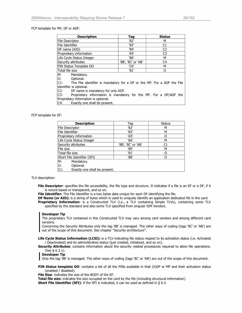
FCP template for EF:
Description Tag Status
File Descriptor '82' M
File Identifier '83' M
Proprietary information 'A5' O
Life Cycle Status Integer '8A' M
Security attributes '8B', '8C' or 'AB' C1
File size '80' M
Total file size '81' O
Short File Identifier (SFI) '88' O
M: Mandatory. O: Optional. C1: Exactly one shall be present.
TLV description:
File Descriptor: specifies the file accessibility, the file type and structure. It indicates if a file is an EF or a DF, if it
is record based or transparent, and so on. File Identifier: The File Identifier is a two bytes data unique for each DF identifying the file.
DF Name (or AID): is a string of bytes which is used to uniquely identify an application dedicated file in the card. Proprietary Information: is a Constructed TLV (i.e., a TLV containing Simple TLVs), containing some TLV
specified by the standard and also some TLV specified from singular SIM Vendors. Developer Tip The proprietary TLV contained in this Constructed TLV may vary among card vendors and among different card versions. Concerning the Security Attributes only the tag '8B' is managed. The other ways of coding (tags '8C' or ‘AB’) are out of the scope of this document. See chapter “Security architecture”.
Life Cycle Status Information (LCSI): is a TLV indicating file status respect to its activation status (i.e. Activated / Deactivated) and its administrative status (just created, initialized, and so on).
Security Attributes: contains information about the security related procedures required to allow file operations. (See § 6.3.1).
Developer Tip Only the tag '8B' is managed. The other ways of coding (tags '8C' or ‘AB’) are out of the scope of this document.
PIN Status template DO: contains a list of all the PINs available in that (A)DF or MF and their activation status (enabled / disabled).
File Size: indicates the size of the BODY of the EF. Total file size: indicates the size occupied on the card by the file (including structural information)
Short File Identifier (SFI): if the SFI is indicated, it can be used as defined in § 6.3.
SIMAlliance - Interoperability Stepping Stones Release 7 27/192
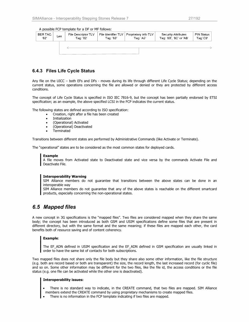
A possible FCP template for a DF or MF follows:
6.4.3 Files Life Cycle Status
Any file on the UICC – both EFs and DFs - moves during its life through different Life Cycle Status; depending on the current status, some operations concerning the file are allowed or denied or they are protected by different access
conditions.
The concept of Life Cycle Status is specified in ISO IEC 7816-9, but the concept has been partially endorsed by ETSI specification; as an example, the above specified LCSI in the FCP indicates the current status.
The following states are defined according to ISO specification:
• Creation, right after a file has been created
• Initialization • (Operational) Activated • (Operational) Deactivated • Terminated
Transitions between different states are performed by Administrative Commands (like Activate or Terminate). The “operational” states are to be considered as the most common states for deployed cards.
Example A file moves from Activated state to Deactivated state and vice versa by the commands Activate File and
Deactivate File.
Interoperability Warning
SIM Alliance members do not guarantee that transitions between the above states can be done in an
interoperable way SIM Alliance members do not guarantee that any of the above states is reachable on the different smartcard
products, especially concerning the non-operational states.
6.5 Mapped files A new concept in 3G specifications is the “mapped files”. Two files are considered mapped when they share the same body; the concept has been introduced as both GSM and USIM specifications define some files that are present in different directory, but with the same format and the same meaning; if these files are mapped each other, the card
benefits both of resource saving and of content coherency.
Example:
The EF_ADN defined in USIM specification and the EF_ADN defined in GSM specification are usually linked in order to have the same list of contacts for both subscriptions.
Two mapped files does not share only the file body but they share also some other information, like the file structure (e.g. both are record based or both are transparent) the size, the record length, the last increased record (for cyclic file)
and so on. Some other information may be different for the two files, like the file id, the access conditions or the file status (e.g. one file can be activated while the other one is deactivated).
Interoperability issues:
• There is no standard way to indicate, in the CREATE command, that two files are mapped. SIM Alliance members extend the CREATE command by using proprietary mechanisms to create mapped files.
• There is no information in the FCP template indicating if two files are mapped.

SIMAlliance - Interoperability Stepping Stones Release 7 28/192
SIMAlliance - Interoperability Stepping Stones Release 7 29/192
7 Mobile Near Field Communication (Mobile NFC)
7.1 Scope The aim of this chapter is to give an overview of the Mobile Near Field Communication (Mobile NFC) technology. Mobile NFC is defined as the combination of contactless services with mobile telephony, based on the NFC technology. A NFC-enabled mobile phone in combination with a secure element (e.g. an UICC) is the basis for usage of contactless services
such as contactless public transport systems or contactless payment systems. The present document is based upon the ETSI Release 7 framework that references Global Platform 2.1; as for Mobile NFC, many updates are under discussions and are expected to be completed in ETSI Release 8 and Global Platform 2.2. As a consequence, many of the limitations included here will not be present anymore in further releases.
7.2 NFC Operating Modes According to ISO/IEC standards NFC devices can be categorized in three different operating modes, where one of the NFC components has either an active or passive role.
7.2.1 Card Emulation Mode
The NFC device reacts like a NFC tag (passive) if getting close to an external NFC Reader (active). This mode is
standardized in ISO/IEC 14443 and can be used e.g. for contactless payment or transport applications. This mode is the one discussed more deeply in this document.
7.2.2 Reader Mode
The NFC device acts like a NFC-Reader (active), searching for NFC tags (passive). This mode is standardized in ISO/IEC 14443 and can be used e.g. for reading NFC Smartposter. This mode is out of scope in this document because there is no API available for the moment, which could be used by Applet developers.
7.2.3 Peer-to-Peer mode
Here a NFC device (active) can communicate to another NFC device (active) to exchange data. This mode is standardized in ISO/IEC 18092 and can be used e.g. to share Bluetooth or WiFi link setup parameters. This mode is out of scope in this document because there is no API available for the moment, which could be used by Applet developers.
7.3 NFC Device Identification
The ISO14443-3 defines individual identifiers for NFC devices, which have the task to separate different NFC-devices during anti-collision procedures (mutual detection phase).
- for Type-A this is the UID (Unique Identifier) with a length of 4,7 or 10 bytes. - for Type-B this is the PUPI (Pseudo-Unique Proximity Card Identifier) with a 4 bytes length.
The UICC must set these values in the CLF registry during SWP initialization phase.
7.4 Overview of Mobile NFC
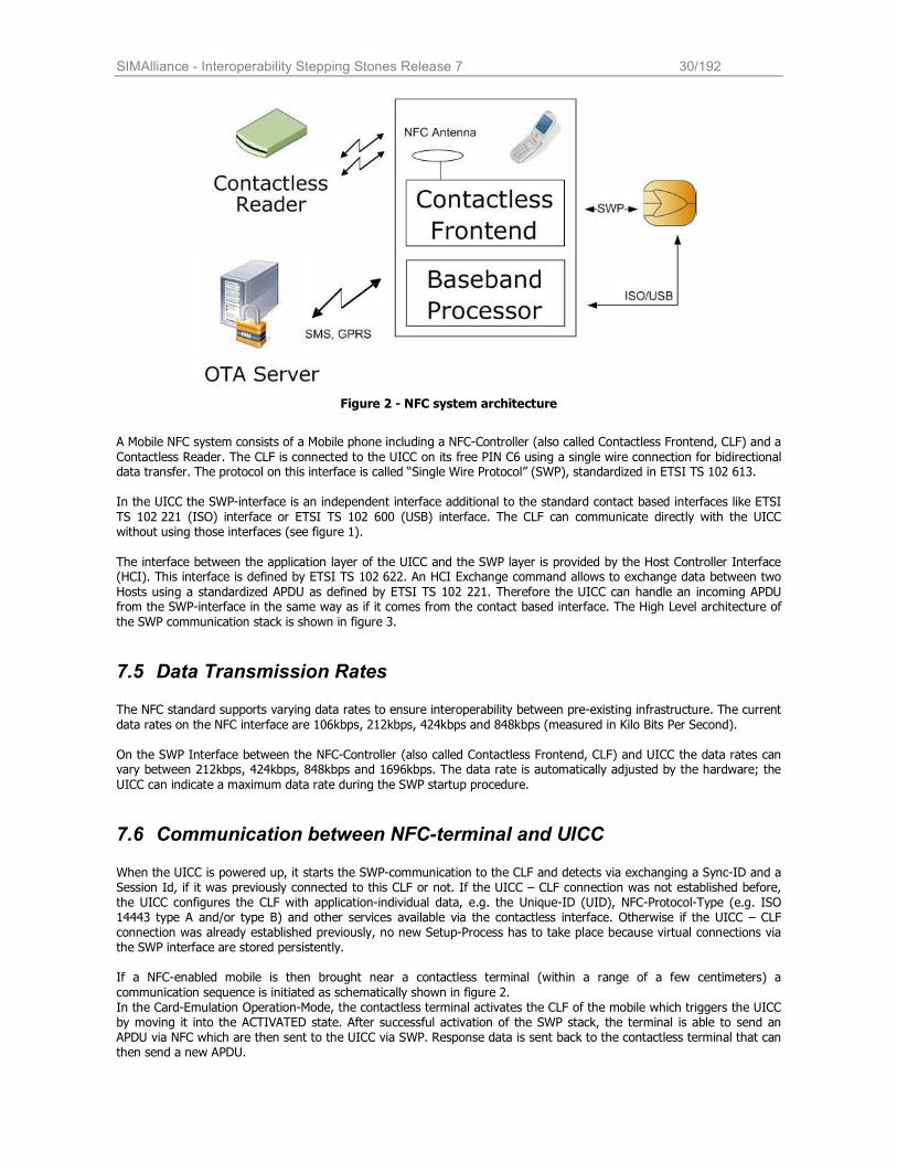
SIMAlliance - Interoperability Stepping Stones Release 7 30/192
Figure 2 - NFC system architecture
A Mobile NFC system consists of a Mobile phone including a NFC-Controller (also called Contactless Frontend, CLF) and a
Contactless Reader. The CLF is connected to the UICC on its free PIN C6 using a single wire connection for bidirectional data transfer. The protocol on this interface is called “Single Wire Protocol” (SWP), standardized in ETSI TS 102 613.
In the UICC the SWP-interface is an independent interface additional to the standard contact based interfaces like ETSI
TS 102 221 (ISO) interface or ETSI TS 102 600 (USB) interface. The CLF can communicate directly with the UICC without using those interfaces (see figure 1).
The interface between the application layer of the UICC and the SWP layer is provided by the Host Controller Interface (HCI). This interface is defined by ETSI TS 102 622. An HCI Exchange command allows to exchange data between two
Hosts using a standardized APDU as defined by ETSI TS 102 221. Therefore the UICC can handle an incoming APDU from the SWP-interface in the same way as if it comes from the contact based interface. The High Level architecture of
the SWP communication stack is shown in figure 3.
7.5 Data Transmission Rates The NFC standard supports varying data rates to ensure interoperability between pre-existing infrastructure. The current
data rates on the NFC interface are 106kbps, 212kbps, 424kbps and 848kbps (measured in Kilo Bits Per Second).
On the SWP Interface between the NFC-Controller (also called Contactless Frontend, CLF) and UICC the data rates can vary between 212kbps, 424kbps, 848kbps and 1696kbps. The data rate is automatically adjusted by the hardware; the
UICC can indicate a maximum data rate during the SWP startup procedure.
7.6 Communication between NFC-terminal and UICC When the UICC is powered up, it starts the SWP-communication to the CLF and detects via exchanging a Sync-ID and a Session Id, if it was previously connected to this CLF or not. If the UICC – CLF connection was not established before, the UICC configures the CLF with application-individual data, e.g. the Unique-ID (UID), NFC-Protocol-Type (e.g. ISO 14443 type A and/or type B) and other services available via the contactless interface. Otherwise if the UICC – CLF connection was already established previously, no new Setup-Process has to take place because virtual connections via the SWP interface are stored persistently.
If a NFC-enabled mobile is then brought near a contactless terminal (within a range of a few centimeters) a
communication sequence is initiated as schematically shown in figure 2. In the Card-Emulation Operation-Mode, the contactless terminal activates the CLF of the mobile which triggers the UICC by moving it into the ACTIVATED state. After successful activation of the SWP stack, the terminal is able to send an APDU via NFC which are then sent to the UICC via SWP. Response data is sent back to the contactless terminal that can then send a new APDU.
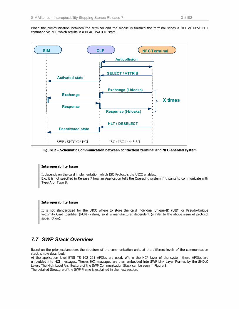
SIMAlliance - Interoperability Stepping Stones Release 7 31/192
When the communication between the terminal and the mobile is finished the terminal sends a HLT or DESELECT
command via NFC which results in a DEACTIVATED state.
Figure 2 – Schematic Communication between contactless terminal and NFC-enabled system
Interoperability Issue
It depends on the card implementation which ISO Protocols the UICC enables. E.g. it is not specified in Release 7 how an Application tells the Operating system if it wants to communicate with Type A or Type B.
Interoperability Issue
It is not standardized for the UICC where to store the card individual Unique-ID (UID) or Pseudo-Unique Proximity Card Identifier (PUPI) values, so it is manufacturer dependent (similar to the above issue of protocol
subscription).
7.7 SWP Stack Overview Based on the prior explanations the structure of the communication units at the different levels of the communication stack is now described. At the application level ETSI TS 102 221 APDUs are used. Within the HCP layer of the system these APDUs are embedded into HCI messages. Theses HCI messages are then embedded into SWP Link Layer Frames by the SHDLC Layer. The High Level Architecture of the SWP Communication Stack can be seen in Figure 3. The detailed Structure of the SWP Frame is explained in the next section.
SWP / SHDLC / HCI ISO / IEC 14443-3/4
SIM CLF
NFC Terminal
SELECT / ATTRIB Activated state
Deactivated state
HLT / DESELECT
Exchange
Response
Response (I-blocks)
Exchange (I-blocks)
X times
Anticollision
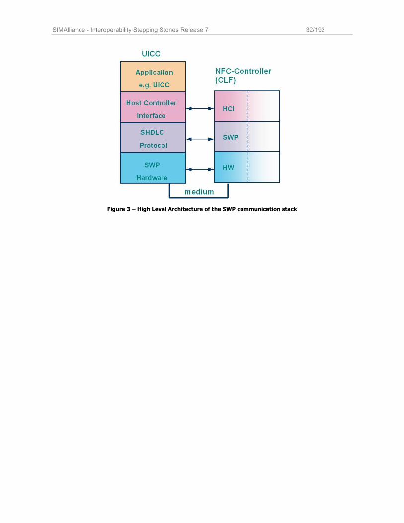
SIMAlliance - Interoperability Stepping Stones Release 7 32/192
Figure 3 – High Level Architecture of the SWP communication stack
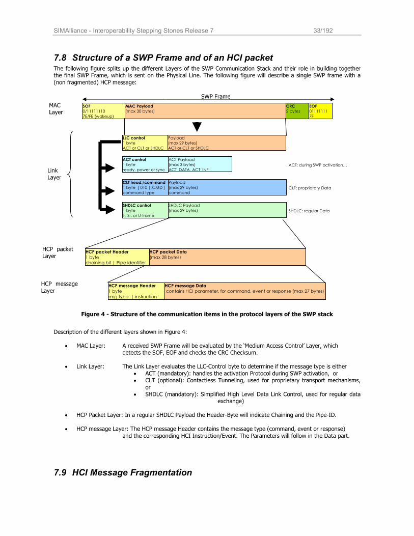
SIMAlliance - Interoperability Stepping Stones Release 7 33/192
SOF
0/11111110
7E/FE (wakeup)
MAC Payload
(max 30 bytes)
CRC
2 bytes
EOF
01111111
7F
LLC control
1 byte
ACT or CLT or SHDLC
Payload
(max 29 bytes)
ACT or CLT or SHDLC
SHDLC control
1 byte
I-, S-, or U-frame
SHDLC Payload
(max 29 bytes)
ACT control
1 byte
ready, power or sync
ACT Payload
(max 3 bytes)
ACT_DATA, ACT_INF
CLT head./command
1 byte [ 010 | CMD ]
command type
Payload
(max 29 bytes)
command
ACT: during SWP activation…
CLT: proprietary Data
HCP packet Header
1 byte
chaining bit | Pipe identifier
HCP packet Data
(max 28 bytes)
HCP message Header
1 byte
msg.type | instruction
HCP message Data
contains HCI parameter, for command, event or response (max 27 bytes)
SHDLC: regular Data
SWP Frame
7.8 Structure of a SWP Frame and of an HCI packet The following figure splits up the different Layers of the SWP Communication Stack and their role in building together the final SWP Frame, which is sent on the Physical Line. The following figure will describe a single SWP frame with a
(non fragmented) HCP message:
Figure 4 - Structure of the communication items in the protocol layers of the SWP stack
Description of the different layers shown in Figure 4:
• MAC Layer: A received SWP Frame will be evaluated by the ‘Medium Access Control’ Layer, which detects the SOF, EOF and checks the CRC Checksum.
• Link Layer: The Link Layer evaluates the LLC-Control byte to determine if the message type is either
• ACT (mandatory): handles the activation Protocol during SWP activation, or • CLT (optional): Contactless Tunneling, used for proprietary transport mechanisms,
or • SHDLC (mandatory): Simplified High Level Data Link Control, used for regular data
exchange)
• HCP Packet Layer: In a regular SHDLC Payload the Header-Byte will indicate Chaining and the Pipe-ID.
• HCP message Layer: The HCP message Header contains the message type (command, event or response)
and the corresponding HCI Instruction/Event. The Parameters will follow in the Data part.
7.9 HCI Message Fragmentation
MAC Layer
Link
Layer
HCP packet Layer
HCP message Layer
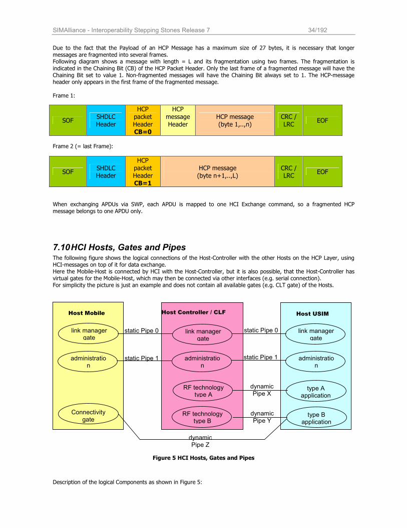
SIMAlliance - Interoperability Stepping Stones Release 7 34/192
Due to the fact that the Payload of an HCP Message has a maximum size of 27 bytes, it is necessary that longer
messages are fragmented into several frames. Following diagram shows a message with length = L and its fragmentation using two frames. The fragmentation is
indicated in the Chaining Bit (CB) of the HCP Packet Header. Only the last frame of a fragmented message will have the Chaining Bit set to value 1. Non-fragmented messages will have the Chaining Bit always set to 1. The HCP-message header only appears in the first frame of the fragmented message. Frame 1:
Frame 2 (= last Frame):
SOF SHDLC Header
HCP packet
Header CB=1
HCP message
(byte n+1,..,L) CRC / LRC
EOF
When exchanging APDUs via SWP, each APDU is mapped to one HCI Exchange command, so a fragmented HCP
message belongs to one APDU only.
7.10 HCI Hosts, Gates and Pipes The following figure shows the logical connections of the Host-Controller with the other Hosts on the HCP Layer, using HCI-messages on top of it for data exchange. Here the Mobile-Host is connected by HCI with the Host-Controller, but it is also possible, that the Host-Controller has virtual gates for the Mobile-Host, which may then be connected via other interfaces (e.g. serial connection). For simplicity the picture is just an example and does not contain all available gates (e.g. CLT gate) of the Hosts.
Figure 5 HCI Hosts, Gates and Pipes
Description of the logical Components as shown in Figure 5:
SOF SHDLC
Header
HCP
packet
Header CB=0
HCP
message
Header
HCP message
(byte 1,..,n)
CRC /
LRC EOF
Host Controller / CLF Host Mobile Host USIM
administration
link manager gate
link manager gate
link manager gate
static Pipe 0
administration
administration
type A application
Connectivity gate
static Pipe 0
dynamic Pipe X
static Pipe 1
dynamic Pipe Z
RF technology type B
RF technology type A
type B application
dynamic Pipe Y
static Pipe 1
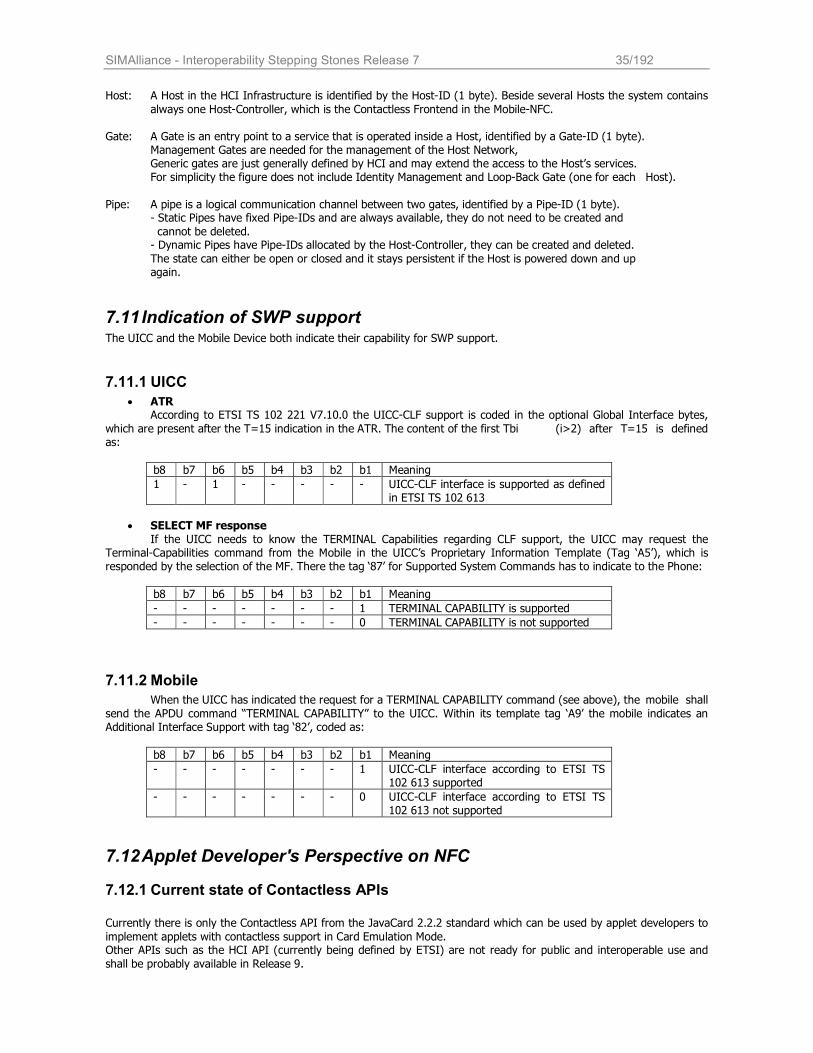
SIMAlliance - Interoperability Stepping Stones Release 7 35/192
Host: A Host in the HCI Infrastructure is identified by the Host-ID (1 byte). Beside several Hosts the system contains
always one Host-Controller, which is the Contactless Frontend in the Mobile-NFC.
Gate: A Gate is an entry point to a service that is operated inside a Host, identified by a Gate-ID (1 byte). Management Gates are needed for the management of the Host Network, Generic gates are just generally defined by HCI and may extend the access to the Host’s services. For simplicity the figure does not include Identity Management and Loop-Back Gate (one for each Host).
Pipe: A pipe is a logical communication channel between two gates, identified by a Pipe-ID (1 byte). - Static Pipes have fixed Pipe-IDs and are always available, they do not need to be created and
cannot be deleted. - Dynamic Pipes have Pipe-IDs allocated by the Host-Controller, they can be created and deleted.
The state can either be open or closed and it stays persistent if the Host is powered down and up again.
7.11 Indication of SWP support The UICC and the Mobile Device both indicate their capability for SWP support.
7.11.1 UICC
• ATR According to ETSI TS 102 221 V7.10.0 the UICC-CLF support is coded in the optional Global Interface bytes,
which are present after the T=15 indication in the ATR. The content of the first Tbi (i>2) after T=15 is defined as:
b8 b7 b6 b5 b4 b3 b2 b1 Meaning
1 - 1 - - - - - UICC-CLF interface is supported as defined in ETSI TS 102 613
• SELECT MF response
If the UICC needs to know the TERMINAL Capabilities regarding CLF support, the UICC may request the Terminal-Capabilities command from the Mobile in the UICC’s Proprietary Information Template (Tag ‘A5’), which is responded by the selection of the MF. There the tag ‘87’ for Supported System Commands has to indicate to the Phone:
b8 b7 b6 b5 b4 b3 b2 b1 Meaning
- - - - - - - 1 TERMINAL CAPABILITY is supported
- - - - - - - 0 TERMINAL CAPABILITY is not supported
7.11.2 Mobile
When the UICC has indicated the request for a TERMINAL CAPABILITY command (see above), the mobile shall
send the APDU command “TERMINAL CAPABILITY” to the UICC. Within its template tag ‘A9’ the mobile indicates an Additional Interface Support with tag ‘82’, coded as:
b8 b7 b6 b5 b4 b3 b2 b1 Meaning
- - - - - - - 1 UICC-CLF interface according to ETSI TS 102 613 supported
- - - - - - - 0 UICC-CLF interface according to ETSI TS 102 613 not supported
7.12 Applet Developer's Perspective on NFC
7.12.1 Current state of Contactless APIs
Currently there is only the Contactless API from the JavaCard 2.2.2 standard which can be used by applet developers to
implement applets with contactless support in Card Emulation Mode. Other APIs such as the HCI API (currently being defined by ETSI) are not ready for public and interoperable use and
shall be probably available in Release 9.
SIMAlliance - Interoperability Stepping Stones Release 7 36/192
To develop interoperable and future proof contactless applications it is advised that an applet developer only uses
standardized contactless APIs. The usage of the JavaCard 2.2.2 Contacless API is described in the following chapter.
7.12.2 JavaCard 2.2.2 Contactless API
The support for contactless applications in JavaCard 2.2.2 is provided by the class javacard.framework.APDU. Using
the method getProtocol() from this class an applet developer can determine on which type of protocol an APDU has been transmitted. Here is a short example: import javacard.framework.APDU; class MyApplet extends javacard.framework.Applet { // ... public void process(APDU apdu) { // ... byte[] buffer = apdu.getBuffer(); byte cla = buffer[ISO7816.OFFSET_CLA]; byte ins = buffer[ISO7816.OFFSET_INS]; // Determine protocol type... byte protolcol = apdu.getProtocol(); if ((protocol == APDU.PROTOCOL_MEDIA_CONTACTLESS_TYPE_A) || (protocol == APDU.PROTOCOL_MEDIA_CONTACTLESS_TYPE_B)) { // Special contactless processing... } else { // Normal behaviour... } //... } }
Developer Tip:
To provide more convenience to the user of a contactless application (e.g. presentation of results of a contactless
communication), a developer might want to use proactive commands from the UICC toolkit.
Therefore it is required that the applet registers to the toolkit event PROACTIVE_HANDLER_AVAILABLE (e.g.
during the execution of the applets process() method during contactless communication). The applet is then triggered after the contactless communication of the application has finished and a further command is executed
on the ETSI TS 102 221 interface. This approach has the advantage that the applet is deregistered from the event after it has been triggered.
This mechanism can be replaced by using the HCI-Connectivity mechanism as mentioned in section 5.4, once it is available as an API.
7.12.3 Considerations on developing applets for contactless systems
There are some general considerations that an applet developer must take into account when developing an applet for a contactless system:
• Processing Time
In some use cases of contactless applications processing time is a critical factor. In these cases the whole
communication between the terminal and the UICC including processing of the applet must not take longer
SIMAlliance - Interoperability Stepping Stones Release 7 37/192
than a few hundred milliseconds. Therefore it is not advised to perform time-critical operations during a
contactless communication.
• Availability of Contactless Interface Another issue of contactless application development is information reliability. Because of the contactless connection between the NFC terminal and the CLF, it is possible that the user exits the electrical field of the NFC-terminal and the connection drops. If this happens during the processing of a contactless application, it may lead to data corruption or application interruptions. To prevent data corruption, it is advised to perform
contactless operations inside an applet using Javacard transactions. Using this approach the applet developer can ensure the consistency of the data processed during applet runtime. However it must be considered that using Javacard Transactions has a major impact on runtime of an applet which is contrary to the timing issue mentioned above. The applet developer is in charge to find the right balance of performance and security.
7.12.4 Connectivity mechanism
The Connectivity mechanism as specified in ETSI TS 102 622 defines a HCI Connectivity Gate, which may be implemented in the Terminal Host. It is implementation dependent whether there is a real HCI to the terminal or whether it is implemented virtually in the CLF and proprietary mechanisms between the CLF and the terminal are used to trigger the sending of the command (e.g. via a Serial Connection). The Connectivity mechanism
• allows a UICC to start a proactive session as defined in TS 102 223 whenever this is required in the context of a contactless transaction.
• allows a Host to launch an application in the terminal Host that is related to the application running in the Host.
This can be e.g. a Java-Midlet in the mobile phone, which is triggered to establish a communication to an applet on the UICC.
• defines commands and events needed by the terminal Host in order perform power management of the
system.
From the Applet Developer view the first of the above items is very useful, because it allows the USIM to immediately
proceed with a Proactive Command even if an Applet was triggered by its process() method (which is usually the case in Card Emulation Mode, where the Applet is selected by its AID and APDUs are sent by the SWP interface to the Applet).
Currently no standard API is existing for the Applet Developer to trigger the Connectivity Mechanism.
Applet Developer Tip Currently the only interoperable way for an Applet to get triggered by the Mobile is to request a POLL-INTERVAL(x seconds) and register to an EVENT_PROACTIVE_HANDLER_AVAILABLE.
For the user-experience it might be an issue, that there is a gap between ending of the SWP communication and the succeeding command on the ISO-Interface which triggers the Applet with the mentioned event.
7.13 Interworking of UICC interfaces
7.13.1 Concurrency
A NFC-enabled UICC features several different interfaces for communication (contact based and contactless) which may cause concurrency issues if these interfaces are used simultaneously.
Applet developers need to be aware that there is no standardized way to make an interface the preferred one for an application. E.g. if an SWP communication is in progress and the mobile phone starts to communicate with the UICC via
the ETSI TS102 221 interface it is not yet defined how the UICC must react to such an event. Despite it is specified that operation of the SWP interface after activation is independent from operation of ISO/USB
interfaces, the JC Runtime Environment Version 2.2.2 does not support multi-threading. This implies that it is not possible for two applications to execute concurrent messages coming on the different
interfaces.
SIMAlliance - Interoperability Stepping Stones Release 7 38/192
Developer tip:
SIM Alliance Members agree that in case a message is received on one interface while the other is executing, the message is not lost but its execution can be delayed until the completion of the execution on the other interface.
Interoperability Issue: On some cards, it is possible to grant a higher priority to the SWP interface in order to respect some timing constraints. However this is not considered as an interoperable solution as it is not supported to configure priority on all cards from SIM Alliance members.
Interoperability Issue:
Concurrency when the card acts in the Reader mode is out of scope and is not guaranteed to be interoperable.
7.13.2 Reset Behavior
There are two different behaviors standardized on how the ISO / USB reset affects the SWP interface:
• JC2.2.2 specifies that the SWP interface has to be reset as well. • ETSI TS 102 613 specifies that the SWP interface must not be affected on an ISO / USB reset and vice versa.
SIM Alliance members agree that the supported behavior is the one indicated in ETSI TS 102 613.
7.14 Support of different NFC Protocols with SWP and HCI As NFC cards, Tags and Terminals are commercially used all over the world, just some of them are implementing APDU based protocols according to ISO14443-3. Many commercial applications are using a proprietary mechanism which is
company specific, e.g. such as MIFARETM or FELICATM.
The following table gives an overview of commercially available protocols / products and gives feedback about the possibility to map them on the existing infrastructure standardized by ETSI TS 102 613 and ETSI TS 102 622.
ISO standard known applications SWP / HCI support
ISO14443-4 Type-A (SAK = standard)
various, e.g. banking, loyalty cards, transport
full support by SHDLC and HCI
ISO14443-4 Type-A
(SAK = non standard)
e.g. MIFARETM only supported with Link-Layer in CLT-Mode and
proprietary higher Layer (note 1)
ISO14443-4 Type B various, e.g. transport,
ticketing
full support by SHDLC and HCI
ISO14443-4 Type B prime e.g. CalypsoTM full support by SHDLC and HCI
ISO18029 Type F e.g. FelicaTM (SonyTM) only supported with Link-Layer in CLT-Mode and
proprietary higher Layer
ISO15693-3 Vicinity Cards full support by SHDLC and HCI
note 1: The MIFARETM Protocol is a proprietary protocol using hardware based stream-cipher for very fast processing. Due to the overall encryption of the full communication and the strong timing requirements, the MIFARETM messages have to be tunnelled through the CLF using the CLT-Mode on the Link-Layer.
As there is currently no API for the CLT-Mode available, a further evaluation is out of scope of this document.
SIMAlliance - Interoperability Stepping Stones Release 7 39/192
8 Java Card Features
8.1 Java Card Language: a Subset of Java Language Because of its small memory resources, the Java Card platform supports only a carefully chosen, customized subset of the Java language’s features. This subset includes features that are well suited for writing programs for smart cards and other small devices while preserving the object-oriented capabilities of the Java programming language. The next table highlights some notable supported and unsupported Java language features.
Supported Java Features Unsupported Java Features
• Small primitive data types: boolean, byte,
short, One-dimensional arrays, Java packages, classes, interfaces, and exceptions,
• Java object-oriented features: inheritance,
virtual methods, overloading and dynamic object creation, access scope, and binding rules,
• The int keyword and 32-bit integer data type
support are optional. • The Garbage Collector
• Large primitive data types: long, double, float
• Characters and strings • Multidimensional arrays
• Dynamic class loading • Security manager
• Threads
• Object serialization • Object cloning
Note: The Garbage Collector is optional according to the Java Card 2.2.2 specification but is mandatory according to the TS 102 241 specification.
8.2 Backward Compatibility The new version of the Java Card specification (revision 2.2.2) allows to run applications developed with the previous version. In facts, Java Card version 2.1, or 2.2, applications will run on Java Card 2.2.2 products without any modifications. Also, an applet developed with the previous version can be converted with the JavaCard 2.2.2 converter tool.
8.3 The Java Card Runtime Environment The Java Card™ platform, version 2.2.2 Runtime Environment contains the Java Card virtual machine (VM), the Java Card Application Programming Interface (API) classes (and industry-specific extensions), and support services.
8.3.1 Atomicity and Transactions
To ensure that the data and the applets stored on a smart card are always defined, even after a power failure or the
card is removed during a session, the concept of atomicity and transaction was created. In the JC API
(javacard.framework.JCSystem class), developers are provided with methods that allow them to write to the memory
atomically; in other words, one memory field is fully updated before the next memory field is updated. Sessions, where the memories are updated atomically, are called transactions. If a transaction is interrupted, all memory fields are
restored to the values set before the transaction started (rollback). Therefore, all memory field updates during a transaction are conditional. The end of the transaction must be committed programmatically (refer to the API description
of the javacard.framework.JCSystem class), so that the updates can be definitively applied.
Interoperability Issue Atomicity and Transactions are currently defined only for javacard memory fields and objects; SIM Alliance members are not interoperable about the applying of such concepts also to file system operations, as it is not explicitly required by the documentation standard.
8.3.2 Security Concept and Firewalls
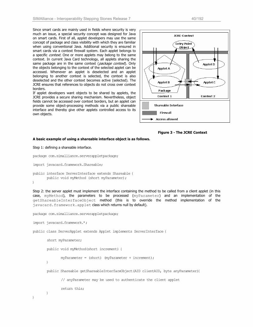
SIMAlliance - Interoperability Stepping Stones Release 7 40/192
Since smart cards are mainly used in fields where security is very
much an issue, a special security concept was designed for Java on smart cards. First of all, applet developers may use the same
concept of package and class visibility with which they are familiar when using conventional Java. Additional security is ensured in smart cards via a context firewall system. Each applet belongs to a specific context. One or more applets may belong to the same context. In current Java Card technology, all applets sharing the
same package are in the same context (package context). Only the objects belonging to the context of the selected applet can be
accessed. Whenever an applet is deselected and an applet belonging to another context is selected, the context is also
deselected and the other context becomes active (selected). The JCRE ensures that references to objects do not cross over context borders. If applet developers want objects to be shared by applets, the JCRE provides a secure sharing mechanism. Nevertheless, object fields cannot be accessed over context borders, but an applet can provide some object-processing methods via a public shareable interface and thereby give other applets controlled access to its own objects.
Figure 3 - The JCRE Context
A basic example of using a shareable interface object is as follows. Step 1: defining a shareable interface. package com.simalliance.serverappletpackage; import javacard.framework.Shareable; public interface ServerInterface extends Shareable {
public void myMethod (short myParameter); }
Step 2: the server applet must implement the interface containing the method to be called from a client applet (in this
case, myMethod), the parameters to be processed (myParameter) and an implementation of the
getShareableInterfaceObject method (this is to override the method implementation of the
javacard.framework.applet class which returns null by default). package com.simalliance.serverappletpackage; import javacard.framework.*; public class ServerApplet extends Applet implements ServerInterface { short myParameter; public void myMethod(short increment) { myParameter = (short) (myParameter + increment); }
public Shareable getShareableInterfaceObject(AID clientAID, byte anyParameter){
// anyParameter may be used to authenticate the client applet
return this; }
}
SIMAlliance - Interoperability Stepping Stones Release 7 41/192
Step 3: the client applet must retrieve the AID of the shareable interface object (sio) from the JCRE. With this, it can
call the method to obtain the sio from the server applet.
package com.simalliance.clientappletpackage; import javacard.framework.*; import com.simalliance.serverappletpackage; private short thisParameter = ANY_NUMBER; static final short SW_SERVER_APPLET_NOT_EXIST = (short) 0x6F01; // Server AID has to be coded in the client applet or assigned in the personalisation private byte[] server_aid_bytes = SERVER_AID_BYTES; public class ClientApplet extends Applet { private void addParameterViaSio() {
// obtain the server AID object AID server_aid = JCSystem.lookupAID(server_aid_bytes, (short)0, (byte)server_aid_bytes.length); if (server_aid == null)
ISOException.throwIt(SW_SERVER_APPLET_NOT_EXIST);
//request sio from server applet ServerInterface sio = (ServerInterface)
(JCSystem.getAppletShareableInterfaceObject(server_aid, ANY_PARAMETER));
//execute myMethod of the server applet sio.myMethod(thisParameter);
} }
8.3.3 Entry Point Objects
In the idea that the security of a smartcard must have a way for non-privileged user processes to request system services performed by privileged “system” routines, entry points objects have been defined. These are objects owned by the JCRE context. They have been flagged as containing entry point methods. This designation allows the methods of these objects to be invoked from any context. The request system service is
performed according to the verification of the method parameters, checked by the JCRE. The firewall restricts accesses to these objects (detect and restrict attempts to store these objects). These entry points objects can be divided between two categories:
• Temporary JCRE Entry Point Objects (i.e. APDU and ProactiveHandler objects) References to these objects can only be used locally, e.g. they can not be stored by the applet in
instance and class attributes
• Permanent JCRE Entry Point Objects (i.e. AID instance and ToolkitRegistry objects) References to these objects can be stored and freely re-used.
8.3.4 Global Arrays
Normally, the firewall would prevent objects from being used in different context. However, some objects need to be accessible from anyone. The Java Card VM allows an object to be designed as “global”. All global arrays are temporary global arrays objects which are owned by the JCRE context. This allows to any context to access to these objects.
Developer tip: An applet can not create Global arrays in a standard way as no API is defined.
SIMAlliance - Interoperability Stepping Stones Release 7 42/192
8.4 The Java Card VM A primary difference between the Java Card virtual machine (JCVM) and the Java virtual machine (JVM) is that the JCVM is implemented as two separate pieces. The first, the on-card portion of the Java Card virtual machine, includes the Java
Card bytecode “interpreter”. The Java Card “Converter” runs on a PC or a workstation. The converter is the off-card piece of the virtual machine. Taken together, they implement all the virtual machine functions—loading Java class files
and executing them with a particular set of semantics. The Java Card Virtual Machine (JCVM) specification defines a subset of the Java programming language and a Java-
compatible VM for smart cards, including binary data representations, file formats, and the JCVM instruction set. The VM for the Java Card platform is implemented on the card itself. The on-card Java Card VM interprets bytecode, manages classes and objects, and so on. The input data for the VM are produced by an external development tool, the Java Card Converter tool, which verifies and prepares the Java classes in a card applet for on-card execution. The converter ensures that the classes conform to the Java Card specification. The output of the converter tool is a Converted Applet (CAP) file, a file that contains all the classes in a Java package in a loadable, executable binary representation.
8.4.1 Summary of Java Card Language Limitations
Language Features Dynamic class loading, security manager (java.lang.SecurityManager), threads, object cloning, and certain aspects of
package access control are not supported.
Keywords native, synchronized, transient, volatile, strictfp are not supported.
Types There is no support for char, double, float, and long, or for multidimensional arrays. Support for int is optional.
Classes and Interfaces Some of the Java core API classes and interfaces (java.io, java.lang, java.util) are partially supported by Java Card.
However, additional classes are defined to support smart cards’ specific features.
Exceptions Some Exception and Error subclasses are omitted because the exceptions and errors they encapsulate cannot arise in
the Java Card platform.
Summary of Java Card VM Constraints
Packages A package can refer to up to 128 other packages
A fully qualified package name is limited to 255 bytes. Note that the character size depends on the character encoding.
A package can have up to 255 classes.
Classes A class can directly or indirectly implement up to 15 interfaces.
An interface can inherit from up to 14 interfaces.
A package can have up to 256 static methods if it contains applets (an applet package), or 255 if it is a library package.
A class can implement up to 128 public or protected instance methods, and up to 128 with package visibility.
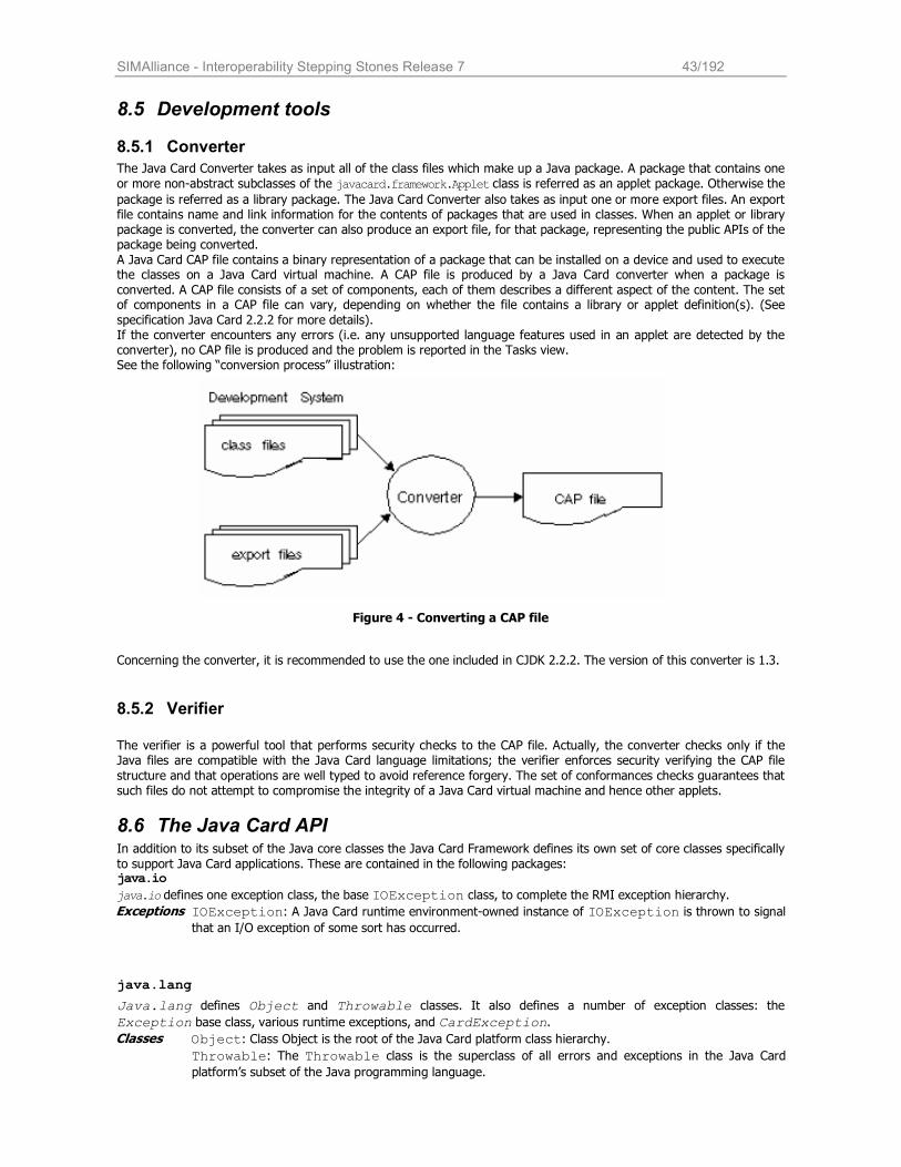
SIMAlliance - Interoperability Stepping Stones Release 7 43/192
8.5 Development tools
8.5.1 Converter
The Java Card Converter takes as input all of the class files which make up a Java package. A package that contains one
or more non-abstract subclasses of the javacard.framework.Applet class is referred as an applet package. Otherwise the
package is referred as a library package. The Java Card Converter also takes as input one or more export files. An export file contains name and link information for the contents of packages that are used in classes. When an applet or library package is converted, the converter can also produce an export file, for that package, representing the public APIs of the package being converted.
A Java Card CAP file contains a binary representation of a package that can be installed on a device and used to execute the classes on a Java Card virtual machine. A CAP file is produced by a Java Card converter when a package is
converted. A CAP file consists of a set of components, each of them describes a different aspect of the content. The set of components in a CAP file can vary, depending on whether the file contains a library or applet definition(s). (See
specification Java Card 2.2.2 for more details). If the converter encounters any errors (i.e. any unsupported language features used in an applet are detected by the converter), no CAP file is produced and the problem is reported in the Tasks view. See the following “conversion process” illustration:
Figure 4 - Converting a CAP file
Concerning the converter, it is recommended to use the one included in CJDK 2.2.2. The version of this converter is 1.3.
8.5.2 Verifier
The verifier is a powerful tool that performs security checks to the CAP file. Actually, the converter checks only if the Java files are compatible with the Java Card language limitations; the verifier enforces security verifying the CAP file
structure and that operations are well typed to avoid reference forgery. The set of conformances checks guarantees that such files do not attempt to compromise the integrity of a Java Card virtual machine and hence other applets.
8.6 The Java Card API In addition to its subset of the Java core classes the Java Card Framework defines its own set of core classes specifically
to support Java Card applications. These are contained in the following packages: java.io
java.io defines one exception class, the base IOException class, to complete the RMI exception hierarchy. Exceptions IOException: A Java Card runtime environment-owned instance of IOException is thrown to signal
that an I/O exception of some sort has occurred.
java.lang
Java.lang defines Object and Throwable classes. It also defines a number of exception classes: the
Exception base class, various runtime exceptions, and CardException.
Object: Class Object is the root of the Java Card platform class hierarchy. Classes
Throwable: The Throwable class is the superclass of all errors and exceptions in the Java Card platform’s subset of the Java programming language.
SIMAlliance - Interoperability Stepping Stones Release 7 44/192
ArithmeticException: A Java Card runtime environment-owned instance of
ArithmeticException is thrown when an exceptional arithmetic condition has occurred.
ArrayIndexOutOfBoundsException: A Java Card runtime environment-owned instance of
ArrayIndexOutOfBoundsException is thrown to indicate that an array has been accessed with an illegal index.
ArrayStoreException: A Java Card runtime environment-owned instance of
ArrayStoreException is thrown to indicate that an attempt has been made to store the wrong type of object into an array of objects.
ClassCastException: A Java Card runtime environment-owned instance of
ClassCastException is thrown to indicate that the code has attempted to cast an object to a subclass of which it is not an instance.
Exception: The class Exception and its subclasses are a form of Throwable that indicate conditions that a reasonable applet might want to catch.
IndexOutOfBoundsException: A Java Card runtime environment-owned instance of
IndexOutOfBoundsException is thrown to indicate that an index of some sort (such as an array) is out of range.
NegativeArraySizeException: A Java Card runtime environment-owned instance of
NegativeArraySizeException is thrown if an applet tries to create an array with negative size.
NullPointerException: A Java Card runtime environment-owned instance of
NullPointerException is thrown when an applet attempts to use null in a case where an object is required.
RuntimeException: It is the superclass of those exceptions that can be thrown during the normal operation of the Java Card Virtual Machine.
Exceptions
SecurityException: A Java Card runtime environment-owned instance of SecurityException is thrown by the Java Card Virtual Machine to indicate a security violation.
javacard.framework
javacard.framework defines the interfaces, classes, and exceptions that compose the core Java Card Framework.
It defines important concepts such as the Application Protocol Data Unit (APDU), the Java Card applet (Applet), the
Java Card System (JCSystem), the Personal Identification Number (PIN), and a utility class. It also defines various ISO7816 constants and various Java Card-specific exceptions. Interfaces ISO7816: defines constants related to ISO 7816-3 and ISO 7816-4. MultiSelectable: identifies applets that can support concurrent selections. PIN: represents a personal identification number used for security (authentication) purposes. Shareable: identifies a shared object. Objects that must be available through the applet firewall must implement this interface. Classes AID: defines an ISO7816-5-conforming Application Identifier associated with an application provider; a mandatory attribute of an applet. APDU: defines an ISO7816-4-conforming Application Protocol Data Unit, which is the communication format used between the applet (on-card) and the host application (off-card).
Applet: defines a Java Card application. All applets must extend this abstract class. JCSystem: provides methods to control the applet life-cycle, resource and transaction management, and inter-applet object sharing and object deletion. OwnerPIN: is an implementation of the PIN interface.
SIMAlliance - Interoperability Stepping Stones Release 7 45/192
Util: provides utility methods for manipulation of arrays and shorts, including arrayCompare(), arrayCopy(), arrayCopyNonAtomic(), arrayFillNonAtomic(), getShort(),
makeShort(), setShort().
Exceptions Various Java Card VM exception classes are defined: APDUException, CardException, CardRuntimeException, ISOException, PINException, SystemException, TransactionException, UserException.
Developer tip:
The OwnerPIN class can be used by Java Card applets to define additional PINs but it does not offer interface to handle PINs defined by network access applications.
javacard.framework.service
javacard.framework.service defines the interfaces, classes, and exceptions for services, including RMI services.
Interfaces Service: defines the methods processCommand(), processDataIn(), and processDataOut().
RemoteService: is a generic Service that gives remote processes access to services on the card.
SecurityService: extends the Service base interface, and provides methods to query the current security
status, including isAuthenticated(), isChannelSecure(), and isCommandSecure().
Classes BasicService: is a default implementation of a Service; it provides helper methods to handle APDUs and service collaboration.
Dispatcher: maintains a registry of services. Use a dispatcher if you want to delegate the processing of an APDU to
several services. A dispatcher can process an APDU completely with the process() method, or dispatch it for
processing by several services with the dispatch() method.
CardRemoteObject: base class to enable or disable remote access to an object from outside the card.
RMIService: this class extends BasicService and implements RemoteService to process RMI requests Exceptions ServiceException: a service-related exception.
javacard.security
javacard.security defines the classes and interfaces for the Java Card security framework. The Java Card specification defines a robust security API that includes various types of private and public keys and algorithms, methods
to compute cyclic redundancy checks (CRCs), message digests, and signatures: Interfaces Generic base interfaces Key, PrivateKey, PublicKey, and SecretKey, and subinterfaces that represent
various types of security keys and algorithms: AESKey, DESKey, DSAKey, DSAPrivateKey, DSAPublicKey, ECKey, ECPrivateKey, ECPublicKey, RSAPrivateCrtKey, RSAPrivateKey, RSAPublicKey, KoreanSEEDKey, HMACKey
SignatureMessageRecovery: an interface that shall be implemented by a subclass of Signature in order to
SIMAlliance - Interoperability Stepping Stones Release 7 46/192
provide message recovery functionality.
Classes Checksum: abstract base class for CRC algorithms KeyAgreement: base class for key-agreement algorithms KeyBuilder: key-object factory
KeyPair: a container to hold a pair of keys, one private, one public
MessageDigest: base class for hashing algorithms. Since JC2.2.2, the method
getInitializedMessageDigestInstance(byte, boolean) can be used to retrieve an instance of the
InitializedMessageDigest class.
InitializedMessageDigest: a subclass of MessageDigest which provides the possibility to initialize the starting hash value. This can be used by the programmer to calculate partial message digests for a subset of the complete data.
RandomData: base class for random-number generators
Signature: base abstract class for signature algorithms Exceptions CryptoException: encryption-related exceptions such as unsupported algorithm or un-initialized key.
Developer Tips:
Not every algorithm is supported by each card (RSA, Elliptic Curves…).
If an unsupported algorithm is used, a CryptoException with the specific reason: NO_SUCH_ALGORITHM is thrown.
javacardx.crypto
This extension package that defines the interface KeyEncryption and the class Cipher, each in its own package for easier export control.
Interfaces KeyEncryption: Generic bas interface used to decrypt an input key used by encryption algorithms Classes Cipher: base abstract class that all ciphers must implement
java.rmi
java.rmi defines the Remote interface and the RemoteException class.
Interfaces Remote: The Remote interface serves to identify interfaces whose methods may be invoked from a CAD client application.
Exceptions RemoteException: A Java Card runtime environment-owned instance of RemoteException is thrown to indicate that a communication-related exception has occurred during the execution of a remote method call.
8.7 New JC 2.2.2 Features The version 2.2.2 of the Java Card specification provides to developers and smart cards issuers the same benefits that the Java Card 2.2.1 specification brought with these following improvements:
SIMAlliance - Interoperability Stepping Stones Release 7 47/192
• Improved Logical Channels support - The Javacard API now supports up to 20 logical channels on any I/O interface (contacted/contactless). It is not mandatory, however, for a card to support the full range of 20 channels.
• External Memory access – An optional extension package offers access to external memory subsystems on both contact and contactless deviced.
• Optional extension framework packages – Additional packages simplify and quicken applet development.
• State of the art cryptographic engines - Provides more security options by supporting the following additional algorithms:
o Hash: SHA-256, SHA-384, SHA-512
o Signature: ISO9796-2 with message recovery, HMAC, Korean SEED MAC NOPAD
o Cipher: Korean SEED NOPAD
8.7.1 Logical Channels
Logical channels allow to a terminal to open up to twenty channels into the smart card (Java Card 2.2.2 platforms). This
mechanism creates the ability to have different session on different logical channel (see ISO7816-4 for logical channels functionality).
Only one logical channel, logical channel 0 (the basic logical channel), is active on card reset. A MANAGE CHANNEL APDU command may be issued on this logical channel to instruct the card to open a new logical channel.
Legacy applets (written for version 2.1 of the Java Card platform), running on version 2.2.2, still work correctly, they do not need to take care about logical channel support.
Since Java Card 2.2, the javacard.framework.MultiSelectable interface is implemented. Multiselectable applets can be selected on multiple logical channels at the same time. They can also accept other applets belonging to the same package being selected simultaneously.
Multiselectable applets shall implement the MultiSelectable interface. In case of multiselection, the Java Card RE
will inform the applet instance by invoking methods MultiSelectable.select() and
MultiSelectable.deselect() during selection and deselection respectively.
The Java Card RE guarantees that an applet, not implementing the Multiselectable Interface, is not selected more than once or concurrently with another applet from the same package. A new method (“isAppletActive(AID)”)indicates whether a specified applet is active on a logical channel. SIMAlliance members guarantee that it is possible to configure 4 logical channels (depending on the card configuration).
Developer Tips
Transient objects, CLEAR_ON_DESELECT type, can be shared between two applets from the same packages even though they are selected on two different channels.
8.7.2 External Memory access
Today’s applications are required to securely store ever-growing amounts of information about the cardholder or network identity. This information includes certificates, images, security keys, and biometric and biographic information. This information sometimes requires large amounts of storage. Before version 2.2.2, applets had to save downloaded applications or user data in valuable persistent memory space.
Java Card 2.2.2 introduces the new optional package javacard.external that provides mechanisms to access memory subsystems which are not directly addressable by the Java Card runtime environment.
The class Memory is used to instantiate an object implementing the MemoryAccess interface, which is used for the
actual data transfer. The requested memory can be either MEMORY_TYPE_EXTENDED_STORAGE (which may be e.g.
flash memory or a mass storage device) or MEMORY_TYPE_MIFARE for MIFARE type of memory, which is used over contactless interfaces.
Reading from and writing to the external memory space usually requires authentication, which must be provided by
every call to according methods of the MemoryAccess object.
8.7.3 Optional extension framework packages
The optional package javacardx.framework offers a framework of classes and interfaces to
SIMAlliance - Interoperability Stepping Stones Release 7 48/192
o Manipulate arrays and primitives of byte, short and int type
o Perform calculations with BCD (Binary Coded Decimals)
o Compute parity bits for DES keys
o Managing BER-TLV structures
o Utility functions for the int primitive type
If the package is implemented, all of the contained sub-packages util, math and tlv shall be included. If the card supports
the int primitive type, the package javacard.framework.util.intx shall be available.
8.7.4 Additional features
There are a number of new features in Java Card 2.2.2 which are optional and not important for the telecom market and therefore are not covered in further detail in this document. For the sake of completeness these features are: Extended length APDUs Extension package for biometric data
8.8 Java Card Remote Method Invocation (JCRMI)
8.8.1 General description
JCRMI can be viewed as a second model of communication. It relies on a subset of the J2SE RMI distributed object model. In one hand, a server application creates and makes accessible remote objects. In another hand, a client application will
request to obtain a reference (16-bit unsigned number which identifies a unique remote object on the card). If the request is accepted by the server, depending on its rules, the client will be able to invoke remote methods on those
remote objects. In this model, the Java Card applet is the server and the host application (in the terminal) is the client.
The client application handles communication among the user, the Java Card applet, and the provider's back-end application. The host program accesses the services provided by the sever applet. It resides on a terminal or card
acceptance device such as a mobile phone.
JCRMI is provided in the extension package javacardx.rmi by the class RMIService. JCRMI messages are
encapsulated within the APDU object passed to the RMIService methods. In other words, JCRMI provides a distributed-object model mechanism on top of the APDU-based messaging model, by which the server and the client communicate, passing method information, arguments, and return values back.
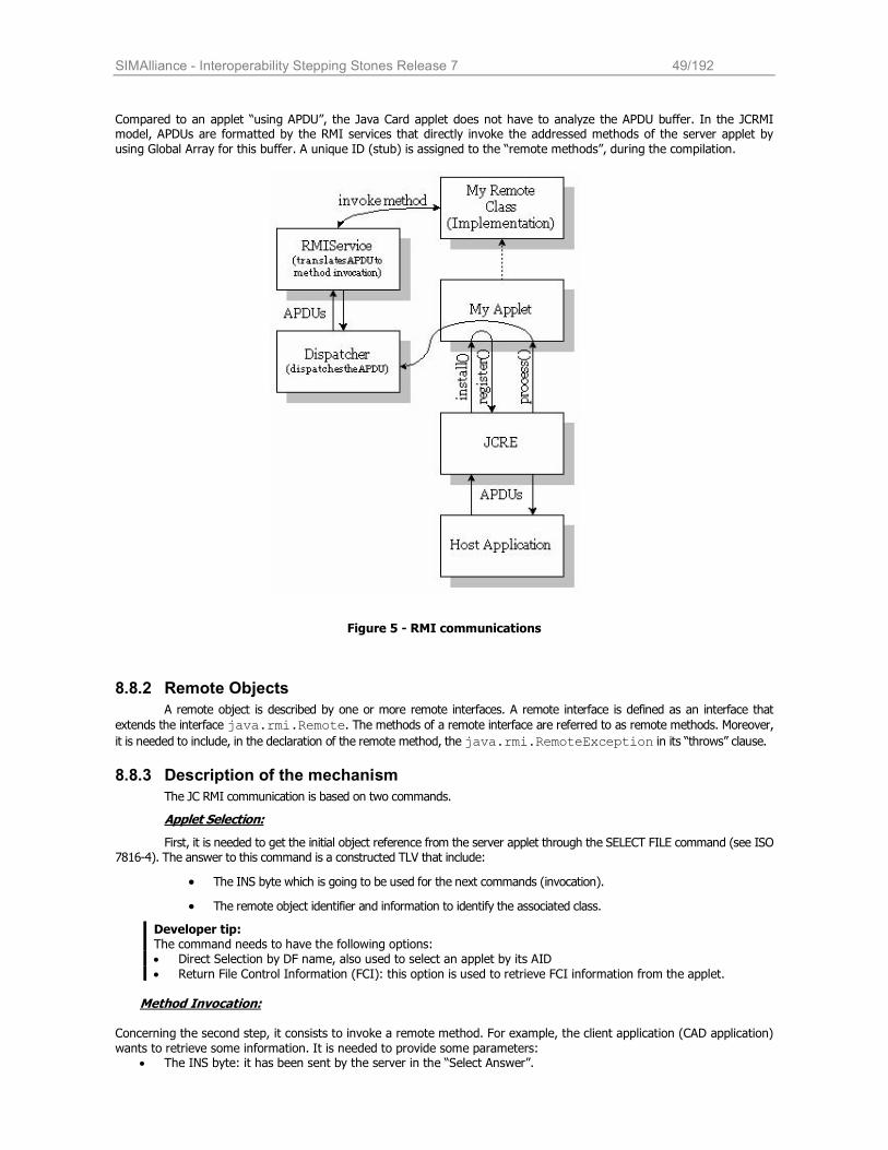
SIMAlliance - Interoperability Stepping Stones Release 7 49/192
Compared to an applet “using APDU”, the Java Card applet does not have to analyze the APDU buffer. In the JCRMI model, APDUs are formatted by the RMI services that directly invoke the addressed methods of the server applet by
using Global Array for this buffer. A unique ID (stub) is assigned to the “remote methods”, during the compilation.
Figure 5 - RMI communications
8.8.2 Remote Objects
A remote object is described by one or more remote interfaces. A remote interface is defined as an interface that
extends the interface java.rmi.Remote. The methods of a remote interface are referred to as remote methods. Moreover,
it is needed to include, in the declaration of the remote method, the java.rmi.RemoteException in its “throws” clause.
8.8.3 Description of the mechanism
The JC RMI communication is based on two commands.
Applet Selection:
First, it is needed to get the initial object reference from the server applet through the SELECT FILE command (see ISO 7816-4). The answer to this command is a constructed TLV that include:
• The INS byte which is going to be used for the next commands (invocation).
• The remote object identifier and information to identify the associated class.
Developer tip: The command needs to have the following options: • Direct Selection by DF name, also used to select an applet by its AID
• Return File Control Information (FCI): this option is used to retrieve FCI information from the applet. Method Invocation:
Concerning the second step, it consists to invoke a remote method. For example, the client application (CAD application)
wants to retrieve some information. It is needed to provide some parameters: • The INS byte: it has been sent by the server in the “Select Answer”.
SIMAlliance - Interoperability Stepping Stones Release 7 50/192
• The remote object identifier: it is the reference on the remote object that has been sent, by the smart card,
during the applet selection. • The invoked method identifier: it permits to retrieve which remote methods is to be execute.
• The parameters’ values of the remote method: it is needed to indicate the length of the argument followed by its value (seems to be in the same order).
The server answers by returning the retrieved information (value, arrays …). The return values are always followed by a good completion status code “0x9000”. In case an error occurs, the remote method throws an exception.
Allocation of incoming objects
As a consequence that in the INVOKE command it is possible to transmit arrays, array objects need to be allocated in the server part (smart card part). Global arrays must be used for this particular type of parameter. These arrays are
temporary objects and they cannot be stored in any object and they can be accessed from all contexts as they are owned by the JCRE.
Functional limitation
• Parameters of a remote method must be any supported data types or any single dimension array of
supported data types.
• Returned values of a remote method must only be one of the following type: • Any supported data type or any single dimension array of supported data type (transmitted
by value) • A void return
• Any remote interface (transmitted by reference using a remote object reference descriptor)
• CAD remote objects can not be passed as arguments to remote methods • Applets can not invoke remote methods on the CAD client
• Method argument data and returned values must not be higher than the size constraint of an APDU.
Realization of the client stub
This is a mandatory step. When the server part has been developed, it is needed to assign a unique identifier to each remote class present in the applet. This is done by the “rmic” tool provided in the Development Kit. The command is the
based on the following example:
“rmic -v1.2 -classpath path -d output_dir class_name” where:
• -v1.2 is a flag required by the Java Card RMI client framework.
• -classpath path identifies the path to the remote class.
• output_dir is the directory in which to place the resulting stubs.
• class_name is the name of the remote class.
The JCRMI Client API is defined in the following packages:
• com.sun.javacard.javax.smartcard.rmiclient contains the core JCRMI Client API. It defines:
• The CardAccessor interface that JCRMI stubs use to access the smart card.
• The CardObjectFactory class that is the base class for JCRMI-stub generation implementations. An instance of this class is associated with one Java Card applet selection
session.
• The JavaCardRMIConnect class that is used by the client application to initialize a JCRMI session, and obtain an initial remote reference.
• A number of Java Card exception subclasses, such as APDUExceptionSubclass, CardExceptionSubclass, CardRuntimeExceptionSubclass, CryptoExceptionSubclass, ISOExceptionSubclass, PINExceptionSubclass, PINException, ServiceExceptionSubclass, SystemExceptionSubclass, TransactionExceptionSubclass, and UserExceptionSubclass.
• javacard.framework defines a number of Java Card exceptions that can be re-thrown on the
client: APDUException, CardException, CardRuntimeException, ISOException, PINException, SystemException, TransactionException, and UserException.
• javacard.framework.service defines the ServiceException, which represents an exception related to the service framework.
SIMAlliance - Interoperability Stepping Stones Release 7 51/192
8.9 Managing Memory and Objects On a Java Card device, memory is the most valuable resource. A garbage collector is present on Rel6 cards. When an object is created, the object and its contents are preserved in non-volatile memory, making it available across sessions.
In some cases application data doesn't need to be persistent - it is transient.
Developer Tip: For frequently updated data it is recommended to use transient. It is possible to check the available memory
through the method: JCSystem.getAvailableMemory(). Remember that transient memory is a limited resource.
As defined previously, two kinds of objects are present for smart cards: Persistent objects:
All objects registered or referenced from a static field become persistent. They are saved in a non-volatile memory area, such as EEPROM. They are not deleted after a power down or reset, and can be accessed, provided that they have a valid reference.
Transient objects:
The Java Card technology does not support the transient keyword. Instead the Java Card API
(javacard.framework.JCSystem) defines four methods that allow you to create transient data at runtime,
and a fifth that lets you check whether an object is transient:
• static byte[] makeTransientByteArray(short length, byte event),
• static byte[] makeTransientBooleanArray(short length, byte event),
• static Object makeTransientObjectArray(short length, byte event),
• static short[] makeTransientShortArray(short length, byte event),
• static byte isTransient(java.lang.Object theObj).
A transient array of primitive data types or Object’s references can be created. A transient array exists as long as references to it remain.
The contents of a transient array get reset to the field's default value (zero, false, or null) when an event
such as a card reset or applet deselection occurs depending on the transient type (CLEAR_ON_RESET and
CLEAR_ON_DESELECT).
Developer Tips For toolkit applets, the use of COD is prohibited.
In a Java Card environment, arrays and primitive types should be declared at object declaration, and you should minimize object instantiation in favor of object reuse. Instantiate objects only once during the applet lifetime. It is
recommended to allocate memory in the install() method as it is invoked only once and the applet is ensured that all the reserved memory is available for all the applet lifetime. In order to avoid resource wasting, a global array has been defined as a buffer that can be used by any applet (see uicc.system).
8.9.1 Garbage collector:
The garbage collector is a mechanism that retrieves every unreferenced object on the card and removes them. In Java
Card, this service is triggered by the invocation of a method JCSystem.requestObjectDeletion().
8.10 Java Card Technology Compatibility Kit The Java Card Technology Compatibility Kit (JC TCK) is a test suite provided by Sun. It has been created to prove that a card is compliant with the current release of Java Card 2.2.1. Tests are grouped in three main packages: the API(s), the JCRE and the JCVM. They guarantee that cards had passed the most current tests. The actual release for those tests is 2.2.1. For example, those tests concern cast of variables, exceptions (arithmetic, out-of-bounds…), APDU, PIN, Transactions, the crypto verification (not mandatory)…
SIMAlliance - Interoperability Stepping Stones Release 7 52/192
8.11 Overview of Versions needed for basic interoperability • JCVM Specification 2.2.1 • JCRE Specification 2.2.1
• JC API Specification 2.2.1 • Sun Cap File Converter 1.3 (CJDK 2.2.1)
• Sun CJDK 2.2.1 • Sun JDK 1.4.1
SIMAlliance - Interoperability Stepping Stones Release 7 53/192
9 Card Application Toolkit (CAT) - USIM Application Toolkit (USAT)
9.1 Scope This chapter describes the Card Application Toolkit (CAT) defined in the ETSI TS 102 223 and the USIM Application
Toolkit (USAT) defined in the 3GPP TS 31.111.
The Card Application Toolkit (CAT) is a set of generic commands and procedures which allow applications, existing in the UICC, to interact and operate with the Mobile Equipment (ME).
The USIM Application Toolkit (USAT) procedures described in the 3GPP TS 31.111 are available when the current Network Access Application (NAA) is the USIM.
9.2 CAT commands The CAT procedures are based on the following commands defined in the ETSI TS 102 221.
• TERMINAL_PROFILE This command is used by the terminal to transmit its CAT capabilities to the applications present on the UICC, let
say the USIM in our case. • ENVELOPE
This command is used to transfer CAT information from the terminal to the USIM. • FETCH
The terminal uses this command to retrieve a proactive command from the UICC (e.g. from the CAT Runtime
Environment or from a CAT application). • TERMINAL_RESPONSE
This command is used by the terminal or UE to send the response for a previously fetched proactive command (e.g. a CAT command).
The card uses the status word ‘91xx’ to indicate that a proactive command is pending. The terminal uses the command FETCH to get the pending proactive command. The terminal sends the response of the proactive command execution
with the command TERMINAL RESPONSE. If the card has no other pending proactive command, it sends the status word ‘9000’ after the TERMINAL RESPONSE to close the proactive session.
The details of the structure and the coding in the data part of the commands TERMINAL_PROFILE, ENVELOPE and TERMINAL_RESPONSE are defined in the ETSI TS 102 223. The proactive commands are also defined in the ETSI TS 102 223. The extension relative to the USIM available when current Network Access Application (NAA) is the USIM are defined in the 3GPP TS 31.111.
9.3 What is a CAT session? A CAT session starts with the TERMINAL PPROFILE and ends with the reset or deactivation of the card. At the beginning of a CAT session, the card performs the following actions:
It triggers any applet registered to the TERMINAL PROFILE event It sends a SET UP MENU system proactive command, if at least one menu entry is registered and enabled by a
selectable Toolkit Applet. Thus, the card supplies a list of items to be incorporated into the UE's menu structure
It sends a SET UP EVENT LIST system proactive command, if at least one of the EVENT_EVENT_DOWNLOAD_* events is registered by a selectable Toolkit Applet. Thus the card supplies a list of events which it wants the UE to provide details of when these events happen
It sends a POLL INTERVAL system proactive command, if at least one Toolkit Applet has requested poll interval duration. The card requests with this command the terminal to adjust the time between the STATUS commands sent to the card by the terminal during idle mode.
SIMAlliance - Interoperability Stepping Stones Release 7 54/192
This is done by the CAT Runtime Environment using the system proactive commands SET UP MENU, SET UP EVENT LIST and POLL INTERVAL. The list depends on the requirements of the toolkit applets installed on the card.
During a CAT session the card shall inform the ME and send the system proactive commands SET UP MENU, SET UP EVENT LIST, POLL INTERVAL and POLLING OFF when a change occurs (e.g. change in the menu list, change of the menu title - an update of the content of EFSUME, change in the event list, change in the polling interval).
9.4 What is a proactive session? A proactive session enables the card to access resources of the UE by sending commands. A proactive session allows toolkit applications in the card to interact and operate with any UE supporting this feature. For this purpose, a toolkit application shall use the (U)SIM or UICC API. A proactive session is a sequence of related CAT commands and responses which starts with the status response '91xx' (proactive command pending) and ends with a status response of '90 00' (normal ending of command) after Terminal Response.
9.5 Multimedia Messages In ETSI TS 102 223 Release 7 the possibility to handle Multimedia Messages (MMS) is introduced. The following chapter
gives an overview of the possibilities of the UICC to handle these MMS.
If a MMS is designated to the UICC, the UICC is informed by this via the ENVELOPE (MMS notification download). This envelope holds a so called “MM1_notification.REQ” (specified in ETSI TS 123 140). Afterwards the UICC can request the
storage of this MMS by issuing a RETRIEVE MULTIMEDIA MESSAGE proactive command. Within this command a file path has to be specified where the message shall be stored by the UE. Additionally the ID of the MMS to store must also be
specified and can be taken from the previously received “MM1_notification.REQ”. After the storage is complete an ENVELOPE (MMS Transfer Status) is send to the UICC indicating the storage status of the MMS. A stored MMS can be displayed by using the DISPLAY MULTIMEDIA MESSAGE proactive command. Along with the ID of the MMS (see “MM1_notification.REQ”) a path must be supplied to the file which holds the MMS from which the MMS shall be read by the UE. The UICC can send a MMS by using the SUBMIT MULTIMEDIA MESSAGE proactive command. The MMS has to be stored in a file before issuing this command as the command holds the file path to the MMS to be sent. After sending the MMS
the UE gives a feedback to the UICC via an ENVELOPE (MMS Transfer Status). For coding of a MMS and other needed parts see ETSI 123 140.
9.6 Terminal Applications In ETSI TS 102 223 Release 7 the possibility to launch applications resided on the UE from the UICC is introduced. The
following paragraph gives an overview of how this can be done.
Seen from the UICC point of view a terminal application is just an entity defined by a port number based on the local host IP-address. Therefore the UICC must be informed about all ports (i.e. terminal applications) available in the UE. This is done by the UE by issuing an ENVELOPE (TERMINAL APPLICATIONS) command (see chapter 7.8.2 in ETSI TS 102 223 Release 7). All needed data for the UICC is provided in this command. Also some information about the type and name of the applications are provided in the ENVELOPE command.
The UICC can start a terminal application by issuing an OPEN CHANNEL (related to Terminal Server Mode) command
using the data received previously in an ENVELOPE (TERMINAL APPLCATIONS) command, i.e. a port number. Afterwards data can be exchanged by via the opened channel.
After finishing the “application session” the UICC shall close the channel. Note that according to ETSI TS 102 223 Release 7 the launched terminal application is not closed. The following flow chart illustrates the flow of data when launching terminal applications by the UICC.
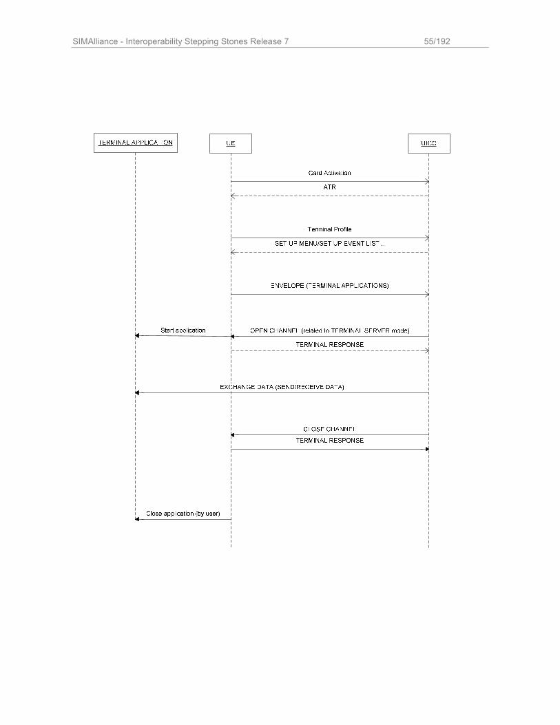
SIMAlliance - Interoperability Stepping Stones Release 7 55/192
SIMAlliance - Interoperability Stepping Stones Release 7 56/192
10 (U)SIM and UICC API description
10.1 Scope This chapter describes the UICC Application Programming Interface and the (U)SIM Application Programming Interface available on a (U)SIM card. It also describes the corresponding Runtime Environment. The UICC API and the CAT Runtime Environment extends the “Java Card™ 2.2.2 API” and the "Java Card™ 2.2.2
Runtime Environment" (JCRE) to allow an application to get access to the functions and data available on a UICC platform as described in ETSI TS 102 221 and ETSI TS 102 223. By this way an application can access the UICC shared file system and the ADF file system or interact with the user equipment by using the toolkit features. The (U)SIM API and its USAT Runtime Environment is an extension of the UICC API and of the CAT Runtime Environment to manage the characteristics of the USAT defined in the 3GPP TS 31.111 or to manage the characteristics of the USIM defined in the 3GPP TS 31.102.
The UICC API is composed of 4 mandatory packages: uicc.system, uicc.toolkit, uicc.access,
uicc.access.fileadministration and 1 optional package: uicc.access.bertlvfile
The (U)SIM API is composed of 2 packages: uicc.usim.toolkit and uicc.usim.access.
The (U)SIM toolkit API consists of the uicc.usim.toolkit package for toolkit features enabling 3GPP TS 31.111 and 3GPP TS 51.014 features. A (U)SIM Application Toolkit is a Toolkit Applet registered in (U)SIM Toolkit Runtime Environment. Network Access Application specific events are available for this type of Toolkit Applet. Corresponding constants are
described in uicc.usim.toolkit.ToolkitConstants interface.
The USAT Toolkit Applet is able to communicate with the terminal by using the Proactive-,
ProactiveResponse-, Envelope- and EnvelopeResponseHandler located in the uicc.toolkit package as the SIM Toolkit Applets. But there are additional features a USAT Toolkit Applet can handle compared to a
SIM Toolkit Applet.
10.2 Toolkit API and CAT Runtime Environment
10.2.1 The CAT Runtime Environment
The CAT Runtime Environment is an addition to the Java Card Runtime Environment (JCRE) in order to manage the Toolkit Applets.
It is composed of the Toolkit Registry, the Toolkit Handlers and the Triggering Entity. The Toolkit Registry handles all the registration status of the Toolkit Applets. The Toolkit Handlers handle the communication between terminal and the Toolkit Applet. The Triggering Entity handles the Toolkit Applet triggering upon reception of some APDU commands sent by the terminal.
10.2.2 Toolkit Applet
10.2.2.1 What is a Toolkit Applet? A Toolkit Applet is a Java Card applet with the following additional capabilities:
It provides an additional entry point: the processToolkit() method It may register to some toolkit events such as the menu selection or the reception of a SMS. When such an event
occurs the CAT Runtime Environment triggers the applet through its processToolkit() method. When triggered, it may request the CAT Runtime Environment to send a proactive command and analyze the mobile
response.
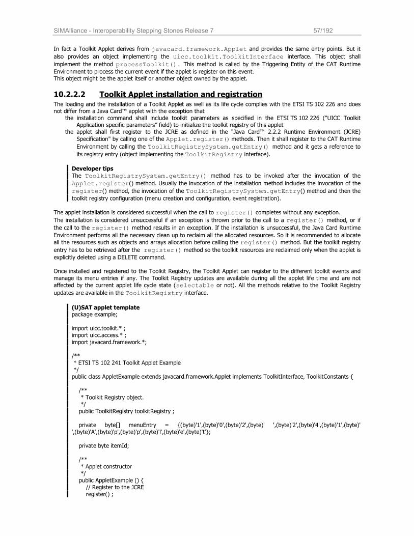
SIMAlliance - Interoperability Stepping Stones Release 7 57/192
In fact a Toolkit Applet derives from javacard.framework.Applet and provides the same entry points. But it
also provides an object implementing the uicc.toolkit.ToolkitInterface interface. This object shall
implement the method processToolkit(). This method is called by the Triggering Entity of the CAT Runtime Environment to process the current event if the applet is register on this event. This object might be the applet itself or another object owned by the applet.
10.2.2.2 Toolkit Applet installation and registration The loading and the installation of a Toolkit Applet as well as its life cycle complies with the ETSI TS 102 226 and does not differ from a Java Card™ applet with the exception that
the installation command shall include toolkit parameters as specified in the ETSI TS 102 226 (“UICC Toolkit Application specific parameters” field) to initialize the toolkit registry of this applet
the applet shall first register to the JCRE as defined in the "Java Card™ 2.2.2 Runtime Environment (JCRE)
Specification" by calling one of the Applet.register() methods. Then it shall register to the CAT Runtime
Environment by calling the ToolkitRegistrySystem.getEntry() method and it gets a reference to
its registry entry (object implementing the ToolkitRegistry interface).
Developer tips
The ToolkitRegistrySystem.getEntry() method has to be invoked after the invocation of the
Applet.register() method. Usually the invocation of the installation method includes the invocation of the
register() method, the invocation of the ToolkitRegistrySystem.getEntry() method and then the toolkit registry configuration (menu creation and configuration, event registration).
The applet installation is considered successful when the call to register() completes without any exception.
The installation is considered unsuccessful if an exception is thrown prior to the call to a register() method, or if
the call to the register() method results in an exception. If the installation is unsuccessful, the Java Card Runtime Environment performs all the necessary clean up to reclaim all the allocated resources. So it is recommended to allocate
all the resources such as objects and arrays allocation before calling the register() method. But the toolkit registry
entry has to be retrieved after the register() method so the toolkit resources are reclaimed only when the applet is explicitly deleted using a DELETE command.
Once installed and registered to the Toolkit Registry, the Toolkit Applet can register to the different toolkit events and
manage its menu entries if any. The Toolkit Registry updates are available during all the applet life time and are not
affected by the current applet life cycle state (selectable or not). All the methods relative to the Toolkit Registry
updates are available in the ToolkitRegistry interface.
(U)SAT applet template package example;
import uicc.toolkit.* ; import uicc.access.* ;
import javacard.framework.*;
/** * ETSI TS 102 241 Toolkit Applet Example
*/ public class AppletExample extends javacard.framework.Applet implements ToolkitInterface, ToolkitConstants {
/** * Toolkit Registry object. */ public ToolkitRegistry toolkitRegistry ; private byte[] menuEntry = {(byte)'1',(byte)'0',(byte)'2',(byte)' ',(byte)'2',(byte)'4',(byte)'1',(byte)' ',(byte)'A',(byte)'p',(byte)'p',(byte)'l',(byte)'e',(byte)'t'};
private byte itemId;
/** * Applet constructor */ public AppletExample () { // Register to the JCRE register() ;
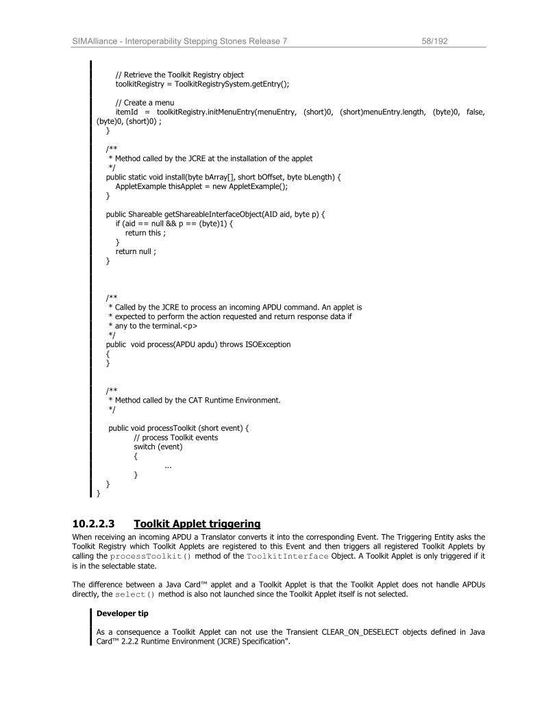
SIMAlliance - Interoperability Stepping Stones Release 7 58/192
// Retrieve the Toolkit Registry object toolkitRegistry = ToolkitRegistrySystem.getEntry();
// Create a menu itemId = toolkitRegistry.initMenuEntry(menuEntry, (short)0, (short)menuEntry.length, (byte)0, false, (byte)0, (short)0) ; }
/**
* Method called by the JCRE at the installation of the applet */
public static void install(byte bArray[], short bOffset, byte bLength) { AppletExample thisApplet = new AppletExample(); } public Shareable getShareableInterfaceObject(AID aid, byte p) { if (aid == null && p == (byte)1) { return this ; } return null ; }
/** * Called by the JCRE to process an incoming APDU command. An applet is * expected to perform the action requested and return response data if * any to the terminal.<p>
*/ public void process(APDU apdu) throws ISOException
{ }
/** * Method called by the CAT Runtime Environment. */ public void processToolkit (short event) {
// process Toolkit events switch (event)
{ ... } } }
10.2.2.3 Toolkit Applet triggering When receiving an incoming APDU a Translator converts it into the corresponding Event. The Triggering Entity asks the Toolkit Registry which Toolkit Applets are registered to this Event and then triggers all registered Toolkit Applets by
calling the processToolkit() method of the ToolkitInterface Object. A Toolkit Applet is only triggered if it is in the selectable state.
The difference between a Java Card™ applet and a Toolkit Applet is that the Toolkit Applet does not handle APDUs
directly, the select() method is also not launched since the Toolkit Applet itself is not selected.
Developer tip As a consequence a Toolkit Applet can not use the Transient CLEAR_ON_DESELECT objects defined in Java Card™ 2.2.2 Runtime Environment (JCRE) Specification".
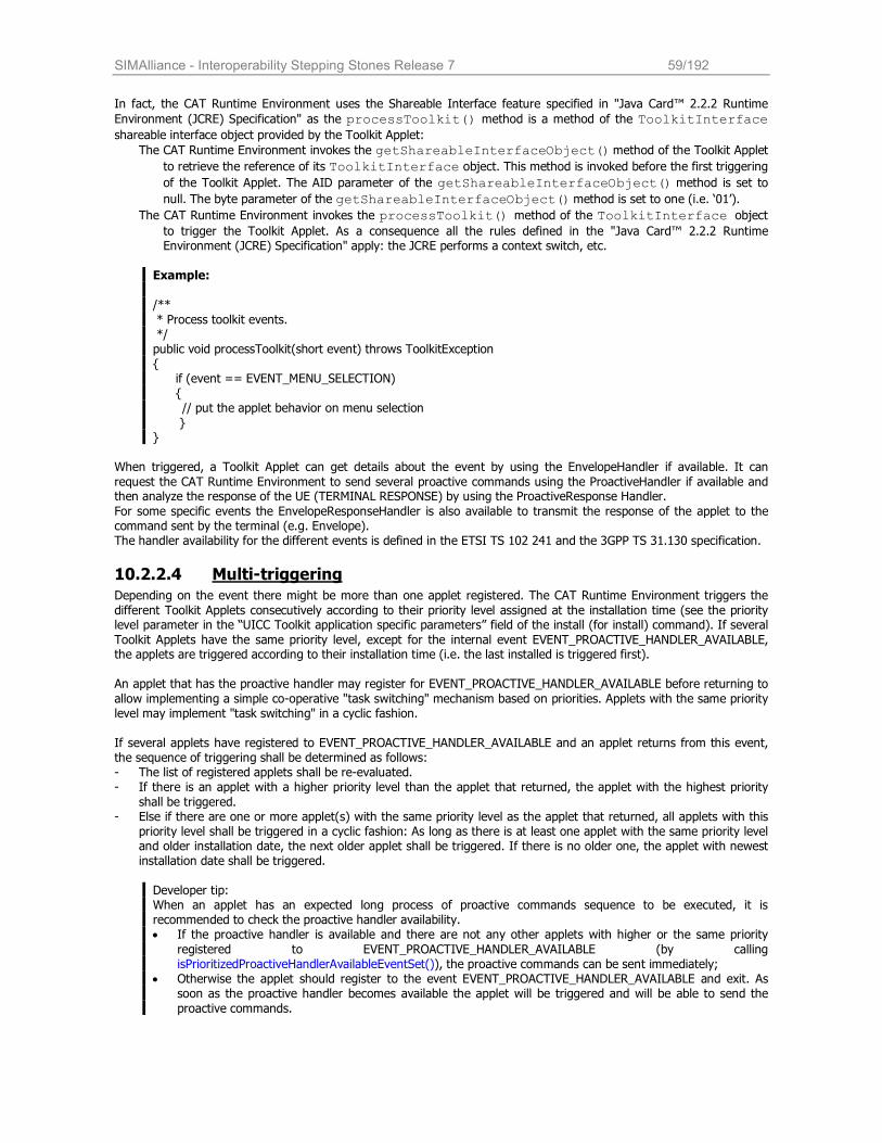
SIMAlliance - Interoperability Stepping Stones Release 7 59/192
In fact, the CAT Runtime Environment uses the Shareable Interface feature specified in "Java Card™ 2.2.2 Runtime
Environment (JCRE) Specification" as the processToolkit() method is a method of the ToolkitInterface shareable interface object provided by the Toolkit Applet:
The CAT Runtime Environment invokes the getShareableInterfaceObject() method of the Toolkit Applet
to retrieve the reference of its ToolkitInterface object. This method is invoked before the first triggering
of the Toolkit Applet. The AID parameter of the getShareableInterfaceObject() method is set to
null. The byte parameter of the getShareableInterfaceObject() method is set to one (i.e. ‘01’).
The CAT Runtime Environment invokes the processToolkit() method of the ToolkitInterface object to trigger the Toolkit Applet. As a consequence all the rules defined in the "Java Card™ 2.2.2 Runtime Environment (JCRE) Specification" apply: the JCRE performs a context switch, etc.
Example: /**
* Process toolkit events. */ public void processToolkit(short event) throws ToolkitException { if (event == EVENT_MENU_SELECTION) { // put the applet behavior on menu selection
} }
When triggered, a Toolkit Applet can get details about the event by using the EnvelopeHandler if available. It can
request the CAT Runtime Environment to send several proactive commands using the ProactiveHandler if available and then analyze the response of the UE (TERMINAL RESPONSE) by using the ProactiveResponse Handler.
For some specific events the EnvelopeResponseHandler is also available to transmit the response of the applet to the command sent by the terminal (e.g. Envelope). The handler availability for the different events is defined in the ETSI TS 102 241 and the 3GPP TS 31.130 specification.
10.2.2.4 Multi-triggering
Depending on the event there might be more than one applet registered. The CAT Runtime Environment triggers the
different Toolkit Applets consecutively according to their priority level assigned at the installation time (see the priority level parameter in the “UICC Toolkit application specific parameters” field of the install (for install) command). If several
Toolkit Applets have the same priority level, except for the internal event EVENT_PROACTIVE_HANDLER_AVAILABLE, the applets are triggered according to their installation time (i.e. the last installed is triggered first).
An applet that has the proactive handler may register for EVENT_PROACTIVE_HANDLER_AVAILABLE before returning to
allow implementing a simple co-operative "task switching" mechanism based on priorities. Applets with the same priority level may implement "task switching" in a cyclic fashion. If several applets have registered to EVENT_PROACTIVE_HANDLER_AVAILABLE and an applet returns from this event, the sequence of triggering shall be determined as follows: - The list of registered applets shall be re-evaluated. - If there is an applet with a higher priority level than the applet that returned, the applet with the highest priority
shall be triggered. - Else if there are one or more applet(s) with the same priority level as the applet that returned, all applets with this
priority level shall be triggered in a cyclic fashion: As long as there is at least one applet with the same priority level and older installation date, the next older applet shall be triggered. If there is no older one, the applet with newest installation date shall be triggered.
Developer tip: When an applet has an expected long process of proactive commands sequence to be executed, it is recommended to check the proactive handler availability. • If the proactive handler is available and there are not any other applets with higher or the same priority
registered to EVENT_PROACTIVE_HANDLER_AVAILABLE (by calling isPrioritizedProactiveHandlerAvailableEventSet()), the proactive commands can be sent immediately;
• Otherwise the applet should register to the event EVENT_PROACTIVE_HANDLER_AVAILABLE and exit. As soon as the proactive handler becomes available the applet will be triggered and will be able to send the
proactive commands.
SIMAlliance - Interoperability Stepping Stones Release 7 60/192
10.2.2.5 Re-entrance Re-entrance refers to the case whereby a proactive session (initiated by an APPLICATION A) execution is interrupted,
and a second APPLICATION B (which can be the same one) is triggered. The application A is then in a suspended mode, and the nested APPLICATION B (in other words, the application triggered while another application is suspended) has its own file and access conditions context. After APPLICATION B has been finished, and no additional event occurs before the terminal response is received, control is returned to the first application, so that its own execution can be finished. Interoperable re-entrancy is supported at least for the following events:
• EVENT_CALL_CONTROL • EVENT_SMS_MO_CONTROL • EVENT_STATUS_COMMAND • EVENT_PROFILE_DOWNLOAD.
Even if only four re-entrant events are supported by all SIM Alliance members’ cards, all members guarantee that no data is lost from a card point of view.
All SIM Alliance members agree that the re-entrance list is highly configurable depending on customers need. System handler availability: SIM Alliance member guaranty at least more than one system handler is available. We strongly recommend applet developer to verify the handler availability with exception mechanism.
As a consequence, the ProactiveHandler may be not available for applets triggered in re-entrance; to overcome this issue, i.e. to perform proactive commands, the re-entrance applet may register itself to the
EVENT_PROACTIVE_HANDLER_AVAILABLE in order to be triggered again when the proactive handler is available. The applet shall save the content of the EnvelopeHandler if needed as it will not be available when triggered on the EVENT_PROACTIVE_HANDLER_AVAILABLE.
10.2.2.6 Exception handling All exceptions thrown by the application are caught by the CAT Runtime Environment. The exceptions are not propagated to the terminal except if the applet is the only one triggered by the current processed event and the
exception is an ISOException with the reason code REPLY_BUSY (‘9300’).
But the ETSI TS 102 241 recommends to use an ISOException with reason code ‘9300’ only for events where reply busy is allowed as defined in the ETSI TS 102 241 and 3GPP TS 31.130.
10.3 Terminal Profile Upon reception of a TERMINAL PROFILE APDU command, the CAT Runtime Environment stores the terminal profile. The content of the Terminal Profile is defined in the ETSI TS 102 223 and 3GPP TS 31.111 specifications. A Toolkit Applet can check the mobile facilities using the different methods defined in the
uicc.toolkit.TerminalProfile class.
10.4 Envelope management
10.4.1 Envelope management
When triggered, a Toolkit Applet can use the EnvelopeHandler to get details about the event. The EnvelopeHandler is available for all the events except:
• EVENT_STATUS_COMMAND, • EVENT_PROFILE_DOWNLOAD, • EVENT_PROACTIVE_HANDLER_AVAILABLE and • EVENT_FIRST_COMMAND_AFTER_ATR.
The EnvelopeHandler contains the list of the simple TLV data objects as sent by the terminal in the ENVELOPE APDU command or is set by the CAT Runtime Environment itself if the event is not generated by an ENVELOPE command (for example, for the event EVENT_EXTERNAL_FILE_UPDATE or event EVENT_FORMATTED_SMS_PP_UPD) . The detail on the different TLV data objects is given in the chapters relative to the ENVELOPE commands and COMPREHENSION_TLV data objects of the ETSI TS 102 223 and the 3GPP TS 31.111 specifications when corresponding
to an ENVELOPE APDU command sent by the terminal. Otherwise the content of the EnvelopeHandler is described in the ETSI TS 102 241 and the 3GPP TS 31.130 specifications in the chapter relative to the event description.
The Toolkit Applet retrieves the EnvelopeHandler by using the uicc.toolkit.
EnvelopeHandlerSystem.getTheHandler() method.
SIMAlliance - Interoperability Stepping Stones Release 7 61/192
For Toolkit Applets using the (U)SIM API, the USATEnvelopeHandler is also available. The
USATEnvelopeHandler is mainly useful when managing the events relative to the SMS_PP and SMS_CB. It provides additional methods to handle the different fields of the SMS message or Cell Broadcast message: methods to get the length, offset and content of the message.
The Toolkit Applet retrieves the USATEnvelopeHandler by using the uicc.usim.toolkit.
USATEnvelopeHandlerSystem.getTheHandler() method
The EnvelopeHandler and the USATEnvelopeHandler are two distinct object instances but their content (TLV
data objects) is exactly the same. The USATEnvelopeHandler availability is the same as the EnvelopeHandler including all the events defined in the ETEI TS 102 241 specification. For example the Toolkit Applet can use the
USATEnvelopeHandler also for the event EVENT_EXTERNAL_FILE_UPDATE.
The Toolkit Applet can post a response to some specific ENVELOPE commands by using the EnvelopeResponse
Handler. The EnvelopeResponseHandler is available only for the following events: EVENT_FORMATTED_SMS_PP_ENV,
EVENT_UNFORMATTED_SMS_PP_ENV, EVENT_CALL_CONTROL_BY_NAA, EVENT_MO_SHORT_MESSAGE_CONTROL_BY_NAA and EVENT_UNRECOGNIZED_ENVELOPE.
The Toolkit Applet retrieves the EnvelopeResponseHandler by using the
EnvelopeResponseHandlerSystem.getTheHandler() method. If the handler is not available, a
ToolkitException with the reason code HANDLER_NOT_AVAILABLE is thrown.
The Toolkit Applet fills the EnvelopeResponseHandler and then posts the response by using the
EnvelopeResponseHandler.post() or the EnvelopeResponseHandler.postAsBERTLV() method. The applet can continue its processing after the call to one of these methods.
10.4.2 EnvelopeResponseHandler management for the event EVENT_FORMATTED_SMS_PP_ENV
The Toolkit Applet fills the EnvelopeResponseHandler by using the methods inherited from the EditHandler.
Then, the applet posts the response using the EnvelopeResponseHandler.post(value) method, value is a Boolean. When the PoR is sent using the SMS_DELIVER_REPORT mechanism, the value is used to indicate if the PoR is sent in a RP-ACK message (value set to true) or if the PoR is sent using a RP-ERROR (value set to false). When the PoR is sent using the SMS_SUBMIT mechanism, the value is not used. The content of the EnvelopeResponseHandler is used to set the applet response to the OTA request. It is inserted by the CAT Runtime Environment in the Additional Response Data of the PoR according to the 3GPP TS 31.115.
This content will be transmitted back to the OTA server.
10.4.3 EnvelopeResponseHandler management for the events EVENT_CALL_CONTROL_BY_NAA or EVENT_MO_SHORT_MESSAGE_ CONTROL_BY_NAA_SMS_PP_ENV
The Toolkit Applet uses the EnvelopeResponseHandler to set the response to the ENVELOPE (CALL CONTROL) APDU command or to the ENVELOPE (MO_SHORT_MESSAGE_CONTROL) APDU command. The Toolkit Applet may fill the EnvelopeResponseHandler by using the method inherited from the EditHandler to define the content of the different data object (Address, etc). See the structure of the ENVELOPE response defined in the 3GPP TS 31.111.
Then, the applet posts the response by using the EnvelopeResponseHandler.postAsBERTLV(value,
tag) method. The value is ignored by the CAT Runtime Environment. The tag shall be set according to the applet response ‘00’ for “Allowed, no modification”, ‘01’ for “Not allowed” and ‘03’ for “Allowed with modifications”. The CAT Runtime Environment uses the tag as the Call control result or the MO short message control result of the response.
Developer tip
The CAT Runtime Environment sends the response to the ENVELOPE before the emission of the next proactive command or when all the Toolkit Applets triggered by the event have finished their processing. If the applet want
to send a specific response, it shall post it before any invocation of the ProactiveHandler.send() method.
SIMAlliance - Interoperability Stepping Stones Release 7 62/192
10.4.4 Details
The EnvelopeHandler, EnvelopeResponseHandler and USATEnvelopeHandler are
Temporary JCRE Entry Point Objects.
When the corresponding getTheHandler() method is called or a method of the handler is called, a system handler
is considered available if a ToolkitException with the reason code HANDLER_NOT_AVAILABLE is not thrown.
EnvelopeHandler and USATEnvelopeHandler:
When available, the EnvelopeHandler remains available and its content remains unchanged from the
invocation to the termination of the processToolkit() method.
The EnvelopeHandler and USATEnvelopeHandler TLV lists are filled with the simple TLV data objects of the ENVELOPE APDU command. The simple TLV data objects are provided in the order given in the ENVELOPE command data if they result of a ENVELOPE command sent by the ME otherwise the order is undefined (for exemple when built by the CAT Runtime Environment for the event EVENT_EXTERNAL_FILE_UPDATE).
Developer tip
The order of the different TLV data objects is not specified so it is recommended to use the
ViewHandler.findTLV() methods to get each COMPREHENSION TLV.
EnvelopeResponseHandler:
The EnvelopeResponseHandler is available (as specified in the ETSI TS 102 241 or the 3GPP TS 31.130 specifications) for all triggered Toolkit Applets, until a Toolkit Applet has posted an envelope response or sent a proactive command.
After a call to the post() method the handler is no longer available.
After the first invocation of the ProactiveHandler.send() method the EnvelopeResponseHandler is no more available.
At the processToolkit() method invocation the TLV-List is cleared.
10.5 Event management
10.5.1 Overview
A Toolkit Applet can register or un-register to the different toolkit events and manage its menu entries using the
different methods defined in the ToolkitRegistry interface. The applet gets the reference to its registry entry by
using the ToolkitRegistrySystem.getEntry() method. All the toolkit registry updates are available during all the applet life time and are not affected by the current applet life
cycle state. In particular, a Toolkit Applet is still considered as registered to an event if it is not in the selectable life
cycle state. But as long as the applet is not in the selectable state, it will not be triggered by the CAT Runtime Environment if the event occurs.
The main methods to manage the registration for the events are the ToolkitRegistry.setEvent() and
ToolkitRegistry.clearEvent() methods with the indication of the event the applet wants to register or un-register to. The CAT Runtime Environment prevents the applet to explicitly register to some specific events relative to the menu management, the timer management, the polling interval, the service management and the file updates management.
In this case, the ToolkitRegistry.setEvent() method throws the exception EVENT_NOT_ALLOWED. The
registration to these events is done by the CAT environment implicitly by particular methods:
The registration to the events EVENT_MENU_SELECTION and EVENT_MENU_SELECTION_HELP_REQUEST is done
when the menu entry has been initialized using the ToolkitRegistry.initMenuEntry() method.
The registration to the event EVENT_TIMER_EXPIRATION is done using the ToolkitRegistry.-
allocateTimer() method.
The registration to the event EVENT_STATUS_COMMAND is done using the ToolkitRegistry.-
requestPollInterval(short) method with the indication of requested duration.
The registration to the event EVENT_EVENT_DOWNLOAD_LOCAL_CONNECTION is done using the Toolkit-
Registry.allocateServiceIdentifer() method.
The registration to the event EVENT_EXTERNAL_FILE_UPDATE is done using one of the ToolkitRegistry.-
registerFileEvent methods with the indication of the file or the file list that shall be monitored.
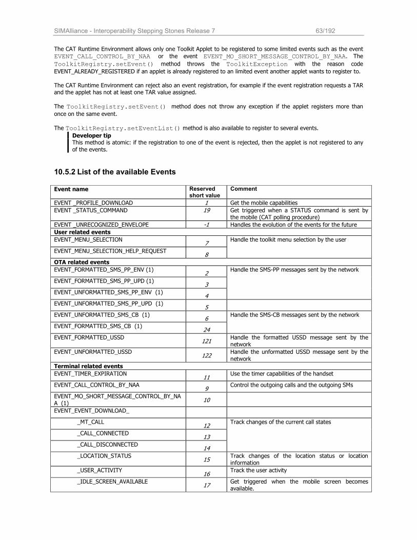
SIMAlliance - Interoperability Stepping Stones Release 7 63/192
The CAT Runtime Environment allows only one Toolkit Applet to be registered to some limited events such as the event
EVENT_CALL_CONTROL_BY_NAA or the event EVENT_MO_SHORT_MESSAGE_CONTROL_BY_NAA. The
ToolkitRegistry.setEvent() method throws the ToolkitException with the reason code
EVENT_ALREADY_REGISTERED if an applet is already registered to an limited event another applet wants to register to. The CAT Runtime Environment can reject also an event registration, for example if the event registration requests a TAR and the applet has not at least one TAR value assigned.
The ToolkitRegistry.setEvent() method does not throw any exception if the applet registers more than once on the same event.
The ToolkitRegistry.setEventList() method is also available to register to several events. Developer tip This method is atomic: if the registration to one of the event is rejected, then the applet is not registered to any
of the events.
10.5.2 List of the available Events
Event name Reserved short value
Comment
EVENT _PROFILE_DOWNLOAD 1 Get the mobile capabilities
EVENT _STATUS_COMMAND 19 Get triggered when a STATUS command is sent by the mobile (CAT polling procedure)
EVENT _UNRECOGNIZED_ENVELOPE -1 Handles the evolution of the events for the future
User related events
EVENT_MENU_SELECTION 7
EVENT_MENU_SELECTION_HELP_REQUEST 8
Handle the toolkit menu selection by the user
OTA related events
EVENT_FORMATTED_SMS_PP_ENV (1) 2
EVENT_FORMATTED_SMS_PP_UPD (1) 3
EVENT_UNFORMATTED_SMS_PP_ENV (1) 4
Handle the SMS-PP messages sent by the network
EVENT_UNFORMATTED_SMS_PP_UPD (1) 5
EVENT_UNFORMATTED_SMS_CB (1) 6
EVENT_FORMATTED_SMS_CB (1) 24
Handle the SMS-CB messages sent by the network
EVENT_FORMATTED_USSD 121
Handle the formatted USSD message sent by the network
EVENT_UNFORMATTED_USSD 122
Handle the unformatted USSD message sent by the
network
Terminal related events
EVENT_TIMER_EXPIRATION 11
Use the timer capabilities of the handset
EVENT_CALL_CONTROL_BY_NAA 9
Control the outgoing calls and the outgoing SMs
EVENT_MO_SHORT_MESSAGE_CONTROL_BY_NAA (1)
10
EVENT_EVENT_DOWNLOAD_
_MT_CALL 12
_CALL_CONNECTED 13
_CALL_DISCONNECTED 14
Track changes of the current call states
_LOCATION_STATUS 15
Track changes of the location status or location information
_USER_ACTIVITY 16
Track the user activity
_IDLE_SCREEN_AVAILABLE 17
Get triggered when the mobile screen becomes available.
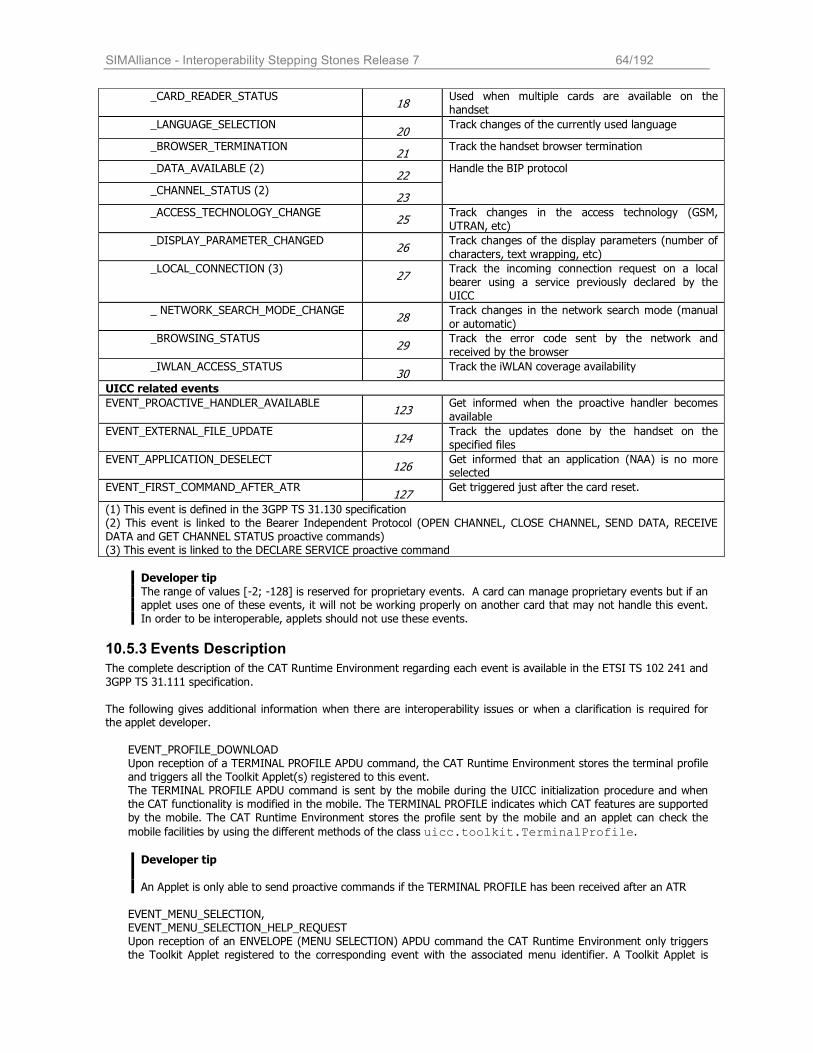
SIMAlliance - Interoperability Stepping Stones Release 7 64/192
_CARD_READER_STATUS 18
Used when multiple cards are available on the handset
_LANGUAGE_SELECTION 20
Track changes of the currently used language
_BROWSER_TERMINATION 21
Track the handset browser termination
_DATA_AVAILABLE (2) 22
_CHANNEL_STATUS (2) 23
Handle the BIP protocol
_ACCESS_TECHNOLOGY_CHANGE 25
Track changes in the access technology (GSM, UTRAN, etc)
_DISPLAY_PARAMETER_CHANGED 26
Track changes of the display parameters (number of
characters, text wrapping, etc)
_LOCAL_CONNECTION (3) 27
Track the incoming connection request on a local bearer using a service previously declared by the UICC
_ NETWORK_SEARCH_MODE_CHANGE 28
Track changes in the network search mode (manual
or automatic)
_BROWSING_STATUS 29
Track the error code sent by the network and
received by the browser
_IWLAN_ACCESS_STATUS 30
Track the iWLAN coverage availability
UICC related events
EVENT_PROACTIVE_HANDLER_AVAILABLE 123
Get informed when the proactive handler becomes
available
EVENT_EXTERNAL_FILE_UPDATE 124
Track the updates done by the handset on the specified files
EVENT_APPLICATION_DESELECT 126
Get informed that an application (NAA) is no more selected
EVENT_FIRST_COMMAND_AFTER_ATR 127
Get triggered just after the card reset.
(1) This event is defined in the 3GPP TS 31.130 specification (2) This event is linked to the Bearer Independent Protocol (OPEN CHANNEL, CLOSE CHANNEL, SEND DATA, RECEIVE DATA and GET CHANNEL STATUS proactive commands) (3) This event is linked to the DECLARE SERVICE proactive command
Developer tip
The range of values [-2; -128] is reserved for proprietary events. A card can manage proprietary events but if an applet uses one of these events, it will not be working properly on another card that may not handle this event.
In order to be interoperable, applets should not use these events.
10.5.3 Events Description
The complete description of the CAT Runtime Environment regarding each event is available in the ETSI TS 102 241 and
3GPP TS 31.111 specification.
The following gives additional information when there are interoperability issues or when a clarification is required for the applet developer.
EVENT_PROFILE_DOWNLOAD Upon reception of a TERMINAL PROFILE APDU command, the CAT Runtime Environment stores the terminal profile and triggers all the Toolkit Applet(s) registered to this event. The TERMINAL PROFILE APDU command is sent by the mobile during the UICC initialization procedure and when the CAT functionality is modified in the mobile. The TERMINAL PROFILE indicates which CAT features are supported by the mobile. The CAT Runtime Environment stores the profile sent by the mobile and an applet can check the
mobile facilities by using the different methods of the class uicc.toolkit.TerminalProfile.
Developer tip
An Applet is only able to send proactive commands if the TERMINAL PROFILE has been received after an ATR
EVENT_MENU_SELECTION, EVENT_MENU_SELECTION_HELP_REQUEST Upon reception of an ENVELOPE (MENU SELECTION) APDU command the CAT Runtime Environment only triggers the Toolkit Applet registered to the corresponding event with the associated menu identifier. A Toolkit Applet is
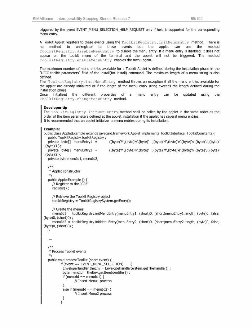
SIMAlliance - Interoperability Stepping Stones Release 7 65/192
triggered by the event EVENT_MENU_SELECTION_HELP_REQUEST only if help is supported for the corresponding
Menu entry.
A Toolkit Applet registers to these events using the ToolkitRegistry.initMenuEntry method. There is no method to un-register to these events but the applet can use the method
ToolkitRegistry.disableMenuEntry to disable the menu entry. If a menu entry is disabled, it does not appear on the toolkit menu of the terminal and the applet will not be triggered. The method
ToolkitRegistry.enableMenuEntry enables the menu again. The maximum number of menu entries available for a Toolkit Applet is defined during the installation phase in the “UICC toolkit parameters” field of the install(for install) command. The maximum length of a menu string is also defined.
The ToolkitRegistry.initMenuEntry method throws an exception if all the menu entries available for the applet are already initialized or if the length of the menu entry string exceeds the length defined during the installation phase.
Once initialized the different properties of a menu entry can be updated using the
ToolkitRegistry.changeMenuEntry method.
Developer tip
The ToolkitRegistry.initMenuEntry method shall be called by the applet in the same order as the order of the item parameters defined at the applet installation if the applet has several menu entries. It is recommended that an applet initialize its menu entries during its installation.
Example:
public class AppletExample extends javacard.framework.Applet implements ToolkitInterface, ToolkitConstants { public ToolkitRegistry toolkitRegistry ;
private byte[] menuEntry1 = {(byte)'M',(byte)'y',(byte)' ',(byte)'M',(byte)'e',(byte)'n',(byte)'u',(byte)' ',(byte)'1'};
private byte[] menuEntry2 = {(byte)'M',(byte)'y',(byte)' ',(byte)'M',(byte)'e',(byte)'n',(byte)'u',(byte)' ',(byte)'2'}; private byte menuId1, menuId2; /** * Applet constructor */
public AppletExample () { // Register to the JCRE
register() ; // Retrieve the Toolkit Registry object toolkitRegistry = ToolkitRegistrySystem.getEntry(); // Create the menus menuId1 = toolkitRegistry.initMenuEntry(menuEntry1, (short)0, (short)menuEntry1.length, (byte)0, false, (byte)0, (short)0) ;
menuId2 = toolkitRegistry.initMenuEntry(menuEntry2, (short)0, (short)menuEntry2.length, (byte)0, false, (byte)0, (short)0) ;
}
...
/** * Process Toolkit events */
public void processToolkit (short event) { if (event == EVENT_MENU_SELECTION) {
EnvelopeHandler theEnv = EnvelopeHandlerSystem.getTheHandler() ; byte menuId = theEnv.getItemIdentifier() ;
if (menuId == menuId1) { // Insert Menu1 process } else if (menuId == menuId2) { // Insert Menu2 process } }
SIMAlliance - Interoperability Stepping Stones Release 7 66/192
}
}
EVENT_TIMER_EXPIRATION Upon reception of an ENVELOPE (TIMER EXPIRATION) APDU command, the CAT Runtime Environment only triggers the Toolkit Applet registered to this event with the associated timer identifier.
A Toolkit Applet registers to this event using the method ToolkitRegistry.allocateTimer, the CAT Runtime Environment will then allocate a timer resource to the applet. The applet may un-register invoking the
ToolkitRegistry.releaseTimer method. Once the applet has allocated a timer, it shall send the proactive command TIMER_MANAGEMENT to start the timer, configure the timer duration or stop the timer.
Developer tip
The method ToolkitRegistry.allocateTimer throws an exception if all the available timers are already allocated or if the maximum number of timer available for this applet is reached. The timer remains allocated to the applet until it explicitly releases it using the method
ToolkitRegistry.releaseTimer. The maximum number of timers available on a UICC is 8 timers. The maximum number of timers available for a
given Toolkit Applet is defined in the UICC Toolkit application specific parameter of the install(for install) command see ETSI TS 102 226.
Example:
ToolkitRegistry reg; byte bTimerId;
final byte[] timerValue = {(byte)0x00, (byte)0x01, (byte)0x00}; /* Timer allocation */ reg = ToolkitRegistrySystem.getEntry(); bTimerId= reg.allocateTimer(); /* Send the proactive command to start the timer */ ProactiveHandler proHdlr = ProactiveHandlerSystem.getTheHandler() ;
proHdlr.init(PRO_CMD_TIMER_MANAGEMENT, (byte)0x00, (byte)DEV_ID_TERMINAL); proHdlr.appendTLV(TAG_TIMER_IDENTIFIER, bTimerId);
proHdlr.appendTLV(TAG_TIMER_VALUE, timerValue, (short)0x00, (short)timerValue.length); proHdlr.send();
EVENT_STATUS_COMMAND Upon reception of an STATUS APDU command the CAT Runtime Environment shall trigger all the Toolkit Applet(s)
registered to this event.
The applet registers to this event by calling the method ToolkitRegistry.requestPollInterval with the indication of the requested duration negotiated with the mobile for the Proactive Polling procedure (STATUS command regularly sent by the terminal according to the ETSI TS 102 221 and ETSI TS 102 223 specifications).
The ToolkitRegistry.requestPollInterval method can be used each time the applet wants to adjust a new duration. If the duration is set to POLL_NO_DURATION, the applet deregisters from the event EVENT_STATUS_COMMAND.
Several applets can register on this event and can request a different duration so the CAT Runtime Environment may adjust the duration. The terminal can also adjust the duration to the one it can offer.
Developer tip

SIMAlliance - Interoperability Stepping Stones Release 7 67/192
The ETSI TS 102 223 specification recommends that applets should not request short time intervals for an
extended period, as this will have an adverse effect on battery life, and should not use this command for time management purposes.
EVENT_FORMATTED_SMS_PP_ENV1 Upon reception of a formatted Short Message Point to Point via the ENVELOPE(SMS-PP DOWNLOAD) APDU command, the CAT Runtime Environment verifies the security of the Short Message according to the 3GPP TS 31.115 specification and then triggers the applet registered to this event and having the corresponding
TAR value.
The toolkit can retrieve the message using the uicc.usim.toolkit.USATEnvelopeHandler defined in the 3GPP TS 31.130. The data is provided deciphered.
The Toolkit Applet can post a response using the EnvelopeResponseHandler.post method. The CAT Runtime Environment will insert the data in the additional data field of the Response Packet, compute the security as defined in the 3GPP TS 31.115 and send the response packet using the SMS_DELIVER_REPORT or the
SMS_SUBMIT. When a SMS is received as a concatenated SMS as defined in the 3GPP TS 23.040, the CAT Runtime Environment
links the different single SMS to re-assemble the original message and fills the USATEnvelopeHandler with
the original message (the concatenation headers are not present and the TP_elements and TS_ServiceCenterAddress fields are the ones of the last received SMS).
See the 3GPP TS 31.130 for details.
A Toolkit Applet registers to this event by using the ToolkitRegistry.setEvent method with the event value set to EVENT_FORMATTED_SMS_PP_ENV. This method throws an exception if no TAR value is defined for the
applet. The TAR value associated to a Toolkit Applet is defined during the applet installation phase: the ”UICC toolkit parameters” field of the install (for install) command can include a list of TAR values to which the applet wants to subscribe to, otherwise the TAR is taken from the AID.
Developer tip The applet is triggered only if the security according to the 3GPP TS 31.115 specification has been successfully verified by the CAT Runtime Environment and if the security level used complies with the minimum security level
required by the applet (parameter defined during the applet installation phase).
Interoperability issue The CAT Runtime Environment may reply busy and not trigger the Toolkit Applet if e.g. a PoR using SMS SUBMIT is required in the incoming message and a proactive session is ongoing.
EVENT_FORMATTED_SMS_PP_UPD1
Upon reception of a formatted Short Message Point to Point via an UPDATE_RECORD EFSMS, the CAT Runtime Environment updates the EFSMS file, converts the UPDATE_RECORD EFSMS to emulate an ENVELOPE (SMS-PP
DOWNLOAD) and fills the uicc.usim.toolkit.USATEnvelopeHandler. Then it verifies the security of the SMS according to the 3GPP TS 31.115 and triggers the applet registered to this event and having the corresponding TAR.
The details of the construction of the USATEnvelopeHandler TLV from the elements of the UPDATE_RECORD EFSMS are described in the 3GPP TS 31.130 specification. The Toolkit Applet can retrieve the message using the
USATEnvelopeHandler defined in the 3GPP TS 31.130. The data is provided deciphered.
1 This event is defined in the 3GPP TS 31.130 specification
SIMAlliance - Interoperability Stepping Stones Release 7 68/192
When a SMS is received as a concatenated SMS as defined in the 3GPP TS 23.040, the CAT Runtime Environment
links the different single SMS to re-assemble the original message and fills the USATEnvelopeHandler with the original message.
Developer tip
• The order of the TLVs given in the USATEnvelopeHandler is not specified so it is recommended to use
the ViewHandler.findTLV() methods to get each COMPREHENSION TLV.
• The EnvelopeResponseHandler is not available. • The applet is triggered only if the security according to the 3GPP TS 31.115 specification has been
successfully verified by the CAT Runtime Environment.
• Even if the EnvelopeHandler is available for these events and contains the same data, the usage of the
USATEnvelopeHandler is recommended as it provides methods distinguished to handle SMS functionality.
EVENT_UNFORMATTED_SMS_PP_ENV2 Upon reception of an unformatted Short Message Point to Point (Single or Concatenated) via the ENVELOPE(SMS-PP
DOWNLOAD) APDU command, the CAT Runtime Environment triggers all the Toolkit Applets registered to this event.
The applet can get the message using the USATEnvelopeHandler. The Toolkit Applet can post a response
using the EnvelopeResponseHandler.post method.
Developer tip
According to the EnvelopeResponseHandler availability rules only the first triggered applet is guaranteed to be able to send back a response.
EVENT_UNFORMATTED_SMS_PP_UPD2 Upon reception of an unformatted Short Message Point to Point (Single or Concatenated) via an UPDATE_RECORD EFSMS, the CAT Runtime Environment updates the EFSMS file, converts the UPDATE_RECORD EFSMS to emulate an
ENVELOPE (SMS-PP DOWNLOAD) and fills in the uicc.usim.toolkit.USATEnvelopeHandler, and triggers all the Toolkit Applets registered to this event.
Developer tips
The order of the TLVs given in the USATEnvelopeHandler is not specified so it is recommended to use the
ViewHandler.findTLV methods to get each COMPREHENSION TLV.
The EnvelopeResponseHandler is not available. The content of EFSMS may have been modified by a previously triggered Toolkit Applet.
EVENT_FORMATTED_SMS_CB2 Upon reception of a formatted Cell Broadcast message via the ENVELOPE (CELL BROADCAST DOWNLOAD) APDU command, the CAT Runtime Environment verifies the security of the Short Message according to the 3GPP TS 31.115 and then triggers the applet registered to this event and having the corresponding TAR.
The toolkit can retrieve the message using the uicc.usim.toolkit.USATEnvelopeHandler defined in the 3GPP TS 31.130. The data are provided deciphered.
When a Cell Broadcast Message is received as multiple pages as defined in the 3GPP TS 23.041 specification, the CAT Runtime Environment links the different single pages to re-assemble the original message and fills the
USATEnvelopeHandler with the original message as a one Cell Broadcast page TLV (the concatenation
headers are not present and the TP_elements and TS_ServiceCenterAddress fields are the ones of the last received SMS).
EVENT_UNFORMATTED_SMS_CB2
SIMAlliance - Interoperability Stepping Stones Release 7 69/192
Upon reception of an unformatted Cell Broadcast message via the ENVELOPE (CELL BROADCAST DOWNLOAD)
APDU command, the CAT Runtime Environment triggers all the Toolkit Applets registered to this event.
EVENT_CALL_CONTROL_BY_NAA EVENT_MO_SHORT_MESSAGE_CONTROL_BY_NAA2 Upon reception of the ENVELOPE (CALL CONTROL) APDU command or the ENVELOPE (MO_SHORT_MESSAGE_ CONTROL) APDU command the CAT Runtime Environment triggers the Toolkit Applet registered to this event. Regardless of the Toolkit Applet state the CAT Runtime Environment does not allow more than one Toolkit Applet to
be registered to this event at a time. In particular, if a Toolkit Applet is registered to this event but not in selectable state the CAT Runtime Environment must not allow another Toolkit Applet to register to this event.
When triggered on this event, this applet can define which response shall be sent to the terminal in response to the ENVELOPE (CALL CONTROL) command in order to allow the call, to reject the call or to allow the call but with
modification. This is done by the applet using the EnvelopeResponseHandler.post() method or the
EnvelopeResponseHandler.postAsBERTLV() method.
Developer tip The Call Control resource is shared between the (U)SAT API and the (SAT) API. So - If an applet is registered to Call Control with (U)SIM API, an applet using SIM API can not register to Call Control and vice versa.
EVENT_EVENT_DOWNLOAD_MT_CALL EVENT_EVENT_DOWNLOAD_CALL_CONNECTED
EVENT_EVENT_DOWNLOAD_CALL_DISCONNECTED EVENT_EVENT_DOWNLOAD_LOCATION_STATUS
EVENT_EVENT_DOWNLOAD_USER_ACTIVITY EVENT_EVENT_DOWNLOAD_IDLE_SCREEN_AVAILABLE EVENT_EVENT_DOWNLOAD_CARD_READER_STATUS EVENT_EVENT_DOWNLOAD_LANGUAGE_SELECTION EVENT_EVENT_DOWNLOAD_BROWSER_TERMINATION EVENT_EVENT_DOWNLOAD_NETWORK_SEARCH EVENT_EVENT_DOWNLOAD_BROWSING_STATUS EVENT_EVENT_DOWNLOAD_ACCESS_TECHNOLOGY_CHANGE
EVENT_EVENT_DOWNLOAD_DISPLAY_PARAMETER_CHANGED Upon reception of the corresponding ENVELOPE (Event Download) APDU command, the CAT Runtime Environment
triggers all the Toolkit Applets registered to the corresponding event.
EVENT_EVENT_DOWNLOAD_DATA_AVAILABLE EVENT_EVENT_DOWNLOAD_CHANNEL_STATUS
Upon reception of the corresponding ENVELOPE (Event Download) APDU command, the CAT Runtime Environment
only triggers the Toolkit Applet registered to the corresponding event with the associated channel identifier.
The applet registers to these events using the ToolkitRegistry.setEvent method but the registration is effective only once the Toolkit Applet has issued a successful OPEN CHANNEL proactive command, and is valid until
the first successful CLOSE CHANNEL with the corresponding channel identifier, or the end of the card session. When a Toolkit Applet sends an OPEN CHANNEL proactive command and receives a TERMINAL RESPONSE with
General Result = ‘0X’, the framework assigns the channel identifier to the calling Toolkit Applet. When a Toolkit Applet sends a CLOSE CHANNEL proactive command and receives a TERMINAL RESPONSE with
General Result =’0X’, the framework releases the corresponding channel identifier.
Developer tip
2 This event is defined in the 3GPP TS 31.130 specification
SIMAlliance - Interoperability Stepping Stones Release 7 70/192
In case of channel drop, we recommend to explicitly close the channel using the CLOSE CHANNEL command prior
to open it again using the OPEN CHANNEL command. In this case, it is also recommended to catch the exception that can be thrown by the CAT Runtime Environment when the applet closes the channel.
EVENT_EVENT_DOWNLOAD_LOCAL_CONNECTION Upon reception of an ENVELOPE (DOWNLOAD LOCAL CONNECTION) APDU command, the CAT Runtime Environment only triggers the Toolkit Applet registered to this event with the associated service identifier. The applet registers to the event by calling the method
ToolkitRegistry.allocateServiceIdentifer. The applet can deregister by calling the method
ToolkitRegistry.releaseServiceIdentifer. Once the applet has allocated a service, it issues the proactive command DECLARE SERVICE to add or delete a service to the mobile service database. The registration to this event is effective once the Toolkit Applet has issued a successful DECLARE SERVICE (add)
proactive command, and is valid until the first successful DECLARE SERVICE (delete) with the corresponding service identifier, or the end of the card session.
EVENT_PROACTIVE_HANDLER_AVAILABLE The CAT Runtime Environment triggers all the Toolkit Applets registered to this event when the
ProactiveHandler is available and all the Toolkit Applets registered to the previous event have been triggered
and have returned from the processToolkit invocation. When a Toolkit Applet is triggered, it is automatically deregistered from this event by the CAT Runtime Environment.
Developer tip
When the Toolkit Applet is triggered on this event, the EnvelopeHandler is not available. We advise that the
Toolkit Applet stores the handler data before registering to this event.
EVENT_APPLICATION_DESELECT
When an application session is terminated, the CAT Runtime Environment triggers all the Toolkit Applets registered to this event.
The AID of the deselected application is available to the Toolkit Applet in the EnvelopeHandler.
Interoperability issue The SIM Alliance members agree that this event is triggered when a first level application including NAA is deselected and independently by the used logical channel. In case of card reset, the CAT Runtime Environment may not trigger the event.
EVENT_FIRST_COMMAND_AFTER_ATR Upon reception of the first APDU after the ATR and before the Status Word of the processed command has been sent back by the UICC, the CAT Runtime Environment triggers all the Toolkit Applet(s) registered to this event. If the first APDU received is a Toolkit Applet triggering APDU (e.g. TERMINAL PROFILE), the Toolkit Applets registered to the event EVENT_FIRST_COMMAND_AFTER_ATR are triggered before the one registered to the event EVENT_TERMINAL_PROFILE if any.
The ProactiveHandler is not available as the CAT session is not open.
EVENT_UNRECOGNIZED_ENVELOPE Upon reception of an unrecognized ENVELOPE APDU command, the CAT Runtime Environment triggers all the
Toolkit Applet(s) registered to this event. An ENVELOPE APDU command is considered as unrecognized by the CAT Runtime Environment if its BER-TLV tag is
not defined in the ToolkitConstants interface. Only the first triggered Toolkit Applet is guaranteed to be able to post a response.
EVENT_EXTERNAL_FILE_UPDATE Upon successful execution of an UPDATE BINARY or UPDATE RECORD or INCREASE APDU or SET DATA command (sent by the Terminal and received by the UICC on the I/O line), the CAT Runtime Environment triggers all the
Toolkit Applets registered to this event with the associated updated file. An Applet is only triggered once per command. For BER TLV files, EVENT_EXTERNAL_FILE_UPDATE is generating after a successful update of a TLV
inside the file. This is done by sending one or more SET DATA APDUs. If the APDUs are successful, the TLV is updated actually and the event is generated in the last SET DATA APDU.
The Toolkit Applet can get the details of the file update by reading the EnvelopeHandler. The details of the
content of the EnvelopeHandler are defined in the ETSI TS 102 241 specification.
The applet registers to this event using one of the ToolkitRegistry.registerFileEvent methods with the indication of the file or the file list that should be monitored.
SIMAlliance - Interoperability Stepping Stones Release 7 71/192
The applet can deregister for a particular file using one of the ToolkitRegistry.deregisterFileEvent methods.
A call to the ToolkitRegistry.clearEvent(EVENT_EXTERNAL_FILE_UPDATE) clears the registration to the event EVENT_EXTERNAL_FILE_UPDATE for all the registered files.
Developer tip
• The order of the TLVs in the EnvelopeHandler is not specified so it is recommended to use the
ViewHandler.findTLV() methods to get each COMPREHENSION TLV. • The value of the File Update Information tag is ‘3B’ (BER-TLV tag for intra-UICC communication as defined in
the ETSI TS 101 220 specification)
• When calling one of the methods ToolkitRegistry.registerFileEvent() or
ToolkitRegistry.deregisterFileEvent(), the value of the fileEvent parameter should be
set to EVENT_EXTERNAL_FILE_UPDATE (as it is the only standardized one at the moment).
Interoperability issue It is not interoperable if the event EVENT_EXTERNAL_FILE_UPDATE is generated on a specific file also in case of updating of a file mapped with that file.
Even if the uicc.access.bertlvfile package is not supported in the UICC, successful SET DATA APDU(s) update on BER-TLV file will trigger the event EVENT_EXTERNAL_FILE_UPDATE.
10.6 Proactive Command
10.6.1 Proactive command management
The proactive protocol (i.e. ‘91xx’, Fetch, Terminal Response) is completely handled by the CAT environment. A Toolkit
Applet can ask the CAT Runtime Environment to send a proactive command through the ProactiveHandler. The Toolkit Applet can get the terminal response to the proactive command (Terminal Response) using the ProactiveResponseHandler.
Developer tip
• As the ProactiveHandler may not be available (re-entrance), it is recommended to check the handler
availability using the exception mechanism: a ToolkitException with the reason code
HANDLER_NOT_AVAILABLE is thrown if the handler is not available.
The Toolkit Applet retrieves the ProactiveHandler using the uicc.toolkit
ProactiveHandlerSystem.getTheHandler()method. Then the applet can build the proactive command:
Initialize the proactive command with the ProactiveHandler.init() method or any of the other methods ProactiveHandler.initDisplayText(), ProactiveHandler.initGetInkey(), ProactiveHandler.initGetInput() or ProactiveHandler.initMoreTime().
Use one of the EditHandler.appendTLV() methods to add the different TLVs that are required for the proactive command as defined in the ETSI TS 102 223 specification
Call the method ProactiveHandler.send to request the CAT Runtime Environment to send this proactive command to the mobile and wait for the Response.
The execution of the Toolkit Applet is paused until the CAT Runtime Environment has transmitted the proactive command and received the response of the terminal. When receiving the Terminal Response, the CAT Runtime Environment resumes the Toolkit Applet.
On the return from the send method, the Toolkit Applet can analyze the response of the mobile:
The send method returns the general result of the proactive command execution (first byte of Result TLV in Terminal Response)
The ProactiveResponseHandler contains all the simple TLV data objects of the TERMINAL RESPONSE command sent by the terminal in response to the proactive command.
The Toolkit Applet retrieves the ProactiveResponseHandler using the
uicc.toolkit.ProactiveHandlerSystem.getTheHandler method. Several methods are defined in the
ProactiveResponseHandler class to ease the terminal response analysis. The methods inherited from the
ViewHander class can also be used.
The send method may throw the exception COMMAND_NOT_ALLOWED if the Proactive command to be sent or one of
its parameter is not allowed by the CAT Runtime Environment:
The CAT Runtime Environment checks the content of ProactiveHandler:
SIMAlliance - Interoperability Stepping Stones Release 7 72/192
The CAT Runtime Environment prevents the Toolkit Applet from sending the following system proactive commands:
SET UP MENU, SET UP EVENT LIST, POLL INTERVAL, POLLING OFF. The CAT Runtime Environment prevents a Toolkit Applet from sending a TIMER MANAGEMENT proactive command
using a timer identifier, which is not allocated to it. The CAT Runtime Environment prevents a Toolkit Applet from sending a DECLARE SERVICE (add, delete) proactive
command using a service identifier, which is not allocated to it. The CAT Runtime Environment prevents a Toolkit Applet from sending a SEND DATA, RECEIVE DATA and CLOSE
CHANNEL proactive commands using a channel identifier, which is not allocated to it.
The CAT Runtime Environment prevents a Toolkit Applet from sending an OPEN CHANNEL proactive command if it exceeds the maximum number of channel allocated to this applet.
All the proactive commands are sent to the terminal as constructed by the Toolkit Applet without any check by the CAT
Runtime Environment.
Developer tips
• Several methods are defined in the ProactiveHandler class to simplify the building of some proactive
commands: initDisplayText(), initGetInkey(), initGetInput(),
initCloseChannel() and initMoreTime().
• At the send method invocation, a pending Toolkit Applet transaction is aborted. • If an applet wants to use the SET UP IDLE MODE TEXT proactive command, the CAT Runtime Environment
cannot guarantee that another Toolkit Applet will not overwrite this text later on.
Example:
byte[] String = {(byte)'H',(byte)'e',(byte)'l',(byte)'l',(byte)'o'} ;
/** * Send a DISPLAY TEXT. */ ProactiveHandler proHdlr = ProactiveHandlerSystem.getTheHandler() ; proHdlr.initDisplayText( (byte)0, (byte)0x04, String,
(short) 0, (short) String.length) ; proHdlr.send() ;
10.6.2 Details on the Proactive Handler and ProactiveResponse Handler
The ProactiveHandler, ProactiveResponseHandler are Temporary JCRE Entry Point Object.
When the corresponding getTheHandler() method is called or a method of the handler is called, a system handler
is considered available if a ToolkitException with the reason code HANDLER_NOT_AVAILABLE is not thrown ProactiveHandler:
The ProactiveHandler is not available if the Terminal Profile command has not yet been processed by the CAT Runtime Environment.
When available the ProactiveHandler remains available until the termination of the processToolkit() method.
If a proactive command is pending the ProactiveHandler may not be available.
At the processToolkit() method invocation the TLV-List is cleared. At the call of its init method the content is cleared and then initialized.
After a call to ProactiveHandler.send() method the content of the handler is not modified by the CAT Runtime Environment.
ProactiveResponseHandler:
The ProactiveResponseHandler is available as soon as the ProactiveHandler is available, its TLV list
is empty before the first call to the ProactiveHandler.send() method. It remains available until the
termination of the processToolkit() method.
The ProactiveResponseHandler is not available if the ProactiveHandler is not available.
The ProactiveResponseHandler TLV list is filled with the simple TLV data objects of the last TERMINAL RESPONSE APDU command. The simple TLV data objects is provided in the order given in the TERMINAL RESPONSE command data.
SIMAlliance - Interoperability Stepping Stones Release 7 73/192
The ProactiveResponseHandler content is updated after each successful call to
ProactiveHandler.send() method and remains unchanged until the next successful call to the
ProactiveHandler.send() method.
10.6.3 System Proactive commands
The CAT Runtime Environment is in charge of the system proactive commands SET UP MENU, SET UP EVENT LIST and
POLL INTERVAL. These commands are used to inform the mobile on the menu items, the event list and the poll interval duration required by any Toolkit Applet installed on the card. But it only contains information relative to the Toolkit
Applets that are in the selectable state. The system proactive commands are sent at the beginning of a CAT session. During a CAT session, the CAT Runtime Environment sends a system proactive command SET UP MENU, SET UP EVENT LIST, POLL INTERVAL or POLLING OFF whenever the menu items, the registered event list or the poll interval duration has changed. The CAT Runtime Environment sends its system proactive command(s) as soon as no proactive session is ongoing and after all the Toolkit Applets registered to the current events have been triggered and have returned from the
processToolkit() method invocation.
The full CAT Runtime Environment behaviour to generate the SETUP MENU , the SETUP EVENT LIST, the POLL INTERVAL and POLLING OFF is described in the ETSI TS 102 241 specification. Concerning the SETUP MENU, here are some highlights:
If one Toolkit Applet indicates that help is available for at least one menu entry, the CAT Runtime Environment indicates to the mobile that help information is available.
The CAT Runtime Environment uses the content of the EFSUME file to set the menu title. The EFSUME file is defined in the ETSI TS 102 222 specification.
If a text attribute different from the default format is provided by at least one menu entry, the CAT Runtime
Environment inserts an Item Text Attribute list. The CAT Runtime Environment provides an Item Icon identifier list only if a icon is requested for all the menu items.
The Icon list qualifier transmitted to the mobile is 'icon is not self explanatory' if one of the applet indicates this qualifier.
The CAT Runtime Environment provides the items to the mobile in the same order than in its Menu Entries’ list. The CAT Runtime Environment provides only the items corresponding to enabled menu entries and if the Toolkit
Applet life cycle state is selectable. The position of a Toolkit Applet menu entry in the Menu Entries’ list depends on the position requested at the applet installation (“position” field in the uicc.toolkit specific parameters of the install (for install) command) but also on the content of the Menu Entries’ list when the applet has been installed. The Menu Entries’ list is managed by the CAT
Runtime Environment regardless of the menu entry state (enable/disable) as well as regardless of the Toolkit Applet(s) life cycle state (e.g. Selectable/Locked, etc.). Several examples are provided in the Annex D of the ETSI TS 102 241 to
illustrate the management of the menu entry order in the Menu Entries’ list of the CAT Runtime Environment. The item identifier used for a menu entry is allocated by the CAT Runtime Environment according to the request done at the applet installation (“identifier” field in the uicc toolkit specific parameters of the install (for install) command). The maximum numbers of menu entries available for the Toolkit Applet and the maximum length available for a menu item text is defined at the applet installation (fields in the uicc,toolkit specific parameters of the install (for install) command).
Interoperability issue To avoid any interoperability issue on a 2G/3G card, the SIM Alliance members recommend to map the EFSUME file
under the DFTELECOM (USIM specification) with the one under the DFGSM (SIM specification).
10.7 File access API and File administration API
10.7.1 Structure of the File System
The UICC file system has the following structure:
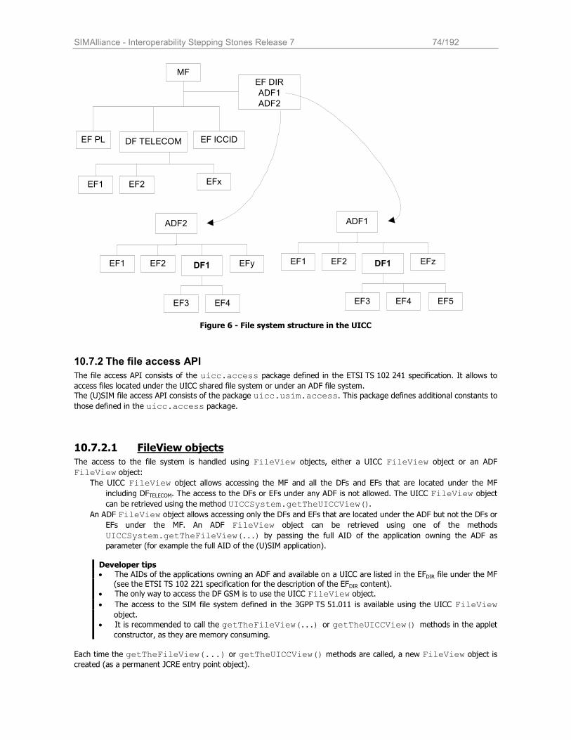
SIMAlliance - Interoperability Stepping Stones Release 7 74/192
MFEF DIR
ADF1
ADF2
DF TELECOM
EF2 EFxEF1
EF PL EF ICCID
ADF1
EF2 EFzEF1 DF1
EF4EF3
ADF2
EF2 EFyEF1 DF1
EF4EF3 EF5
Figure 6 - File system structure in the UICC
10.7.2 The file access API
The file access API consists of the uicc.access package defined in the ETSI TS 102 241 specification. It allows to access files located under the UICC shared file system or under an ADF file system.
The (U)SIM file access API consists of the package uicc.usim.access. This package defines additional constants to
those defined in the uicc.access package.
10.7.2.1 FileView objects
The access to the file system is handled using FileView objects, either a UICC FileView object or an ADF
FileView object:
The UICC FileView object allows accessing the MF and all the DFs and EFs that are located under the MF
including DFTELECOM. The access to the DFs or EFs under any ADF is not allowed. The UICC FileView object
can be retrieved using the method UICCSystem.getTheUICCView().
An ADF FileView object allows accessing only the DFs and EFs that are located under the ADF but not the DFs or
EFs under the MF. An ADF FileView object can be retrieved using one of the methods
UICCSystem.getTheFileView(...) by passing the full AID of the application owning the ADF as parameter (for example the full AID of the (U)SIM application).
Developer tips • The AIDs of the applications owning an ADF and available on a UICC are listed in the EFDIR file under the MF
(see the ETSI TS 102 221 specification for the description of the EFDIR content).
• The only way to access the DF GSM is to use the UICC FileView object.
• The access to the SIM file system defined in the 3GPP TS 51.011 is available using the UICC FileView object.
• It is recommended to call the getTheFileView(...) or getTheUICCView() methods in the applet constructor, as they are memory consuming.
Each time the getTheFileView(...) or getTheUICCView() methods are called, a new FileView object is created (as a permanent JCRE entry point object).
SIMAlliance - Interoperability Stepping Stones Release 7 75/192
A separate and independent file context3 is associated to each FileView object: the operation performed on files in a
given FileView object shall not affect the file context associated with any other FileView object. After the applet termination, the context (current selected file, etc) may remain depending on the object type and can be retrieved during the next applet execution. The context can be transient or persistent depending on what was required by the Applet during the creation of the
FileView object (event parameter of the getTheFileView() or getTheUICCView() methods).
The root of the context of a FileView object is the MF for the UICC FileView or the ADF for an ADF FileView.
At the creation of a FileView object or when the transient context of a FileView is cleared, the current DF of the
FileView's context is set to the root.
The access control privileges associated with each FileView object is given by the Access Domain of the Toolkit Applet during its installation phase. The Access Domain of the Toolkit Applet is defined in the UICC Access Application specific parameter field of the install (for install) command (tag value ‘81’). A Toolkit Applet can have an Access Domain
relative to the access to the UICC file system part and an Access Domain for each ADF file system part.
The access domain for the UICC file system part is associated to the UICC FileView objects; the access domain for an
ADF file system part is associated to the ADF FileView objects relative to this ADF.
Each time a method of the FileView object is invoked, the access control privilege of the FileView object is verified against the access rules of the given DF/EF as described in the ETSI TS 102 221.
10.7.2.2 FileView operations
The different methods defined in the FileView interface are
select(): selects a file or a directory using the file ID or the SFI.
status(): returns the FCP of the current selected DF
readBinary(): reads the content of the current transparent EF
readRecord(): reads a record or a part of a record of the current linear fixed/cyclic EF
updateBinary(): updates the content of the current transparent EF
updateRecord(): updates a record or a part of a record of the current linear fixed/cyclic EF
searchRecord(): searches a pattern in the current linear fixed/cyclic EF
increase(): increases the current record of the current cyclic EF
activateFile(): activates the currently selected EF
deactivateFile(): deactivates the currently selected EF These methods implement in fact the same functionality as the SELECT, STATUS, READ BINARY, READ RECORD, UPDATE BINARY, UPDATE RECORD, SEARCH RECORD, INCREASE, ACTIVATE, DEACTIVATE commands defined in the ETSI TS 102 221 specifications.
Developer tips
• When a non-shareable file is selected using one of the select() methods, this file is no more accessible by other applets, by the Remote File management application or by terminal operations. Furthermore when a non-shareable file is selected by the mobile, this file is no longer accessible for any other application. The file
is accessible again when the application selects another file. If the FileView context is transient, the file becomes also accessible when the context is cleared.
• The reserved FID '7FFF' can be used as a FID for the ADF to select the root of an ADF FileView object • When selecting a cyclic file the current record number is undefined.
3 The file context includes at least information about the current DF, the current EF and the current record (for linear fixed or cyclic files).
SIMAlliance - Interoperability Stepping Stones Release 7 76/192
Example:
public static FileView uiccView;
private byte[] Buffer = {(byte)'H',(byte)'e',(byte)'l',(byte)'l',(byte)'o'} ; // get a reference to the UICC interface uiccView = UICCSystem.getTheUICCView(JCSystem.CLEAR_ON_RESET);
uiccView.select( MF_ID); uiccView.select( UICCConstants.FID_DF_TELECOM)
uiccView.select( EF_TEST_ID); // Update file
uiccView.updateBinary((short) 0, Buffer, (short) 0, Buffer.length);
10.7.3 File Administration API
A specific API is available for the file administration (create, delete and resize operations) in the
uicc.access.fileAdministration package defined in the ETSI TS 102 241 specification.
10.7.3.1 AdminFileView objects
The administrative access to the file system is handled using AdminFileView objects. Two AdminFileView objects are available, one for the UICC file system administration and one for an ADF file system administration:
The UICC AdminFileView object allows administrating the EFs and DFs under the MF. The UICC
AdminFileView object can be retrieved using the method getTheUICCAdminFileView(...) defined
in the AdminFileViewBuilder class.
An ADF AdminFileView object allows administrating only the DFs and EFs that are located under the ADF. An
ADF AdminFileView object can be retrieved using one of the methods getTheAdminFileView(...) with passing the full AID of the application owning the ADF as parameter (for example the full AID of the
(U)SIM application). The getTheAdminFileView(...) methods are defined in the
AdminFileViewBuilder class.
The AdminFileView interface inherits of the FileView interface and the AdminFileView objects follows the
behavior of the FileView objects: the associated context can be persistent or transient; the context initialization rules are the same, etc.
The access control privileges associated to each AdminFileView object is given by the Administrative Access Domain of the Toolkit Applet during its installation phase. The Administrative Access Domain of the Toolkit Applet is defined in the UICC Administrative Access Application specific parameter field of the install (for install) command (tag value ‘82’). A Toolkit Applet can have an Administrative Access Domain relative to the access to the UICC file system part and an Administrative Access Domain for each ADF file system part.
The Administrative Access Domain for the UICC file system part is associated to the UICC AdminFileView objects;
the Administrative Access Domain for an ADF file system part is associated to the ADF AdminFileView objects relative to this ADF.
Each time a method of the AdminFileView object is invoked, the access control privilege of the AdminFileView object is verified against the access rules of the given DF/EF as described in the ETSI TS 102 221.
10.7.3.2 AdminFileView operations
The different methods defined in the AdminFileView interface are
createFile(): creates a new EF or a new DF under the current DF or ADF
deleteFile(): deletes an EF under the current DF or deletes a DF with its complete sub-tree.
resizeFile(): resize an EF DF under the current DF or ADF
These methods implement in fact the same functionality as the CREATE, DELETE and RESIZE commands defined in the ETSI TS 102 222 specifications.
The details of the different methods are defined in the ETSI TS 102 241.
If EF or DF file already exists, or if memory is not available for creation, then an AdminException is thrown.
SIMAlliance - Interoperability Stepping Stones Release 7 77/192
Developer tip
The createFile() and resizeFile() methods uses a ViewHandler object to define a data field identical to the one used for the CREATE and RESIZE commands. The
uicc.system.HandlerBuilder.buildTLVHandler() method is useful to create a ViewHandler
object. The TLV content can be set either when creating the ViewHandler object or later on. In this case the
handler can be cast to an EditHandler and then filled with the TLV content. To avoid memory allocation
during lifecycle of the applet, it is recommended to invoke the buildTLVHandler() method in the constructor of the applet.
The AdminFileView interface inherits of the FileView interface so all methods such as select(),
readBinary() and so one are also available.
When the deleteFile()method is invoked, SIM Alliance members agree that they all provide mechanisms to recover memory space but the implementation of this features can be different for the SIM Alliance members.
private byte [] fileDescriptor = {
(byte)0x42,(byte)0x21,(byte)0x00,(byte)0x04}; // File Descriptor: EF linear fixed, record length 4 private short fileId = (short)0x8302; // File Id private byte LCSI = (byte)0x05; // LCSI activated private byte [] securityAttribute = {
(byte)0xAC,(byte)0x00, // Security attribute (EF Arr) (byte)0x01,(byte)0x01, // Security attribute (SD 1, record nb)
(byte)0x00,(byte)0x01}; // Security attribute (SD 0, record nb)
private short fileSize = 0x0064; // File Size (25 rec * 4 bytes = 100)
private byte [] sfiTLV = {
(byte)0x88,(byte)0x00}; // sfiTLV – no SFI – length = 0
AdminFileView adminFileView= AdminFileViewBuilder.getTheUICCAdminFileView(JCSystem.CLEAR_ON_RESET) ;
// Select the MF adminFileView.select((short)0x3F00);
// Create EF AF80 createCmd = HandlerBuilder.buildTLVHandler(HandlerBuilder.EDIT_HANDLER, (short )255); createCmd.appendTLV((byte)0x82, fileDescriptor, (short)0x00, (short)fileDescriptor.length); createCmd.appendTLV((byte)0x83, fileId); createCmd.appendTLV((byte)0x8A, LCSI); createCmd.appendTLV((byte)0x8B, securityAttribute, (short)0x00, (short)securityAttribute.length); createCmd.appendTLV((byte)0x80, fileSize);
createCmd.appendArray(sfiTLV, (short)0x00, (short) sfiTLV.length);
adminFileView.createFile(createCmd);
10.7.4 BER TLV file access API
Package uicc.access.bertlvfile is the API for administrating and accessing BER-TLV files.
AdminBERTLVFileView objects and methods are used for the administrating of BER-TLV files. Interface
BERTLVFileView defines methods for accessing BER-TLV files. BER TLV files functions may be optionally supported in the UICC. If it is supported, the uicc.access.bertlvfile package and the 32-bit integer data type as mentioned in the Chapter 8 is mandatory. SIMAlliance members cannot guarantee that this optional package is existed in all their UICC cards.
10.7.4.1 BERTLVFileView operations
SIMAlliance - Interoperability Stepping Stones Release 7 78/192
The interface uicc.access.bertlvfile.BERTLVFileView extends the interface uicc.access.FileView, i.e. objects implementing the interface BERTLVFileView inherit FileView functionality. If BER TLV files functions are supported in the UICC, the getTheFileView() and getTheUICCView() methods defined in the UICCSystem class shall return the reference of an object implementing the BERTLVFileView interface. The methods defined in the AdminBERTLVFileView to access BER-TLV files are
• deleteData(): for deleting a data object in the current BER-TLV structure EF. • getTAGList(): for getting the list of TAGs already allocated in the current BER-TLV structure EF.
• retrieveData(): for retrieving a part of a data object from the current BER-TLV structure EF. • setData(): for setting a data object in the current BER-TLV structure EF.
10.7.4.2 AdminBERTLVFileView operations
The AdminBERTLVFileView interface defines the administrative methods for administrating BER TLV files. If BER
TLV files functions are supported in the UICC, the getAdminFileView() and getTheUICCAdminFileView()
methods defined in the AdminFileViewBuilder class shall return the reference of an object implementing the
AdminBERTLVFileView interface.
10.8 Short Messages and their handling with the USIM API
10.8.1 Single SMS-PP
There are two ways for card to receive a single Short Message Point to Point: through an ENVELOPE (SMS_PP_DOWNLOAD) APDU, or through an UPATE_RECORD EFSMS APDU.
The received message can be: Formatted accordingly to identify explicitly a toolkit application (see chapter Structure of the Command Packet) Unformatted and send data to all registered toolkit application.
10.8.1.1.1 TLV structure for Envelopes (SMS-PP DOWNLOAD) APDU Command: ’80 C2 00 00 Length’
Data Buffer:
When receiving an envelope APDU containing an formatted SMS_DOWLOAD, the USIM Toolkit Framework:
• Verifies the security of the short message,
• Triggers the Toolkit Applet registered to EVENT_FORMATTED_SMS_PP_ENV, and with
corresponding TAR,
• Takes the optional Application Data posted by the triggered toolkit application if present, • Secures and sends response packet using SMS-DELIVER-REPORT or SMS-SUBMIT according the SPI
byte 2
When the applet is triggered, the data of short message in the TLV structure are deciphered.
When receiving an envelope APDU containing an Unformatted SMS_DATADOWNLOAD BER simple TLV, the USIM Toolkit
Framework triggers all the toolkit applications registered to the EVENT_UNFORMATTED_SMS_PP_ENV.
10.8.1.1.2 TLV structure for Update EFSMS APDU: APDU Command: ‘0X DC 00 02 Length’ (see ETSI TS 102 221) Data Buffer:
Tag Length Device Identities TS-SCA 3GPP-SMS TPDU (DELIVER)
’D1’ XX Tag Length Src Dst Tag Length Val Tag Length 3GPP TS 23.040
TPUD
’82 ’ ’02’ ’83’ ’81’ ’06’ XX …. ‘8B’ XX TPUDL 3GPP TS
31.115
Data
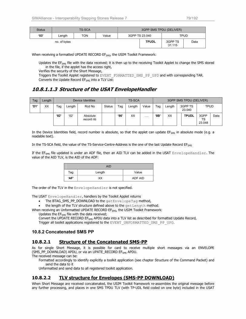
SIMAlliance - Interoperability Stepping Stones Release 7 79/192
Status TS-SCA 3GPP SMS TPDU (DELIVER)
‘03’ Length TON Value 3GPP TS 23.040 TPUD
no. of bytes TPUDL 3GPP TS 31.115
Data
When receiving a formatted UPDATE RECORD EFSMS, the USIM Toolkit Framework:
Updates the EFSMS file with the data received; it is then up to the receiving Toolkit Applet to change the SMS stored
in the file, if the applet has the access right, Verifies the security of the Short Message,
Triggers the Toolkit Applet registered to EVENT_FORMATTED_SMS_PP_UPD and with corresponding TAR. Converts the Update Record EFSMS into a TLV List:
10.8.1.1.3 Structure of the USAT EnvelopeHandler
Tag Length Device Identities TS-SCA 3GPP SMS TPDU (DELIVER)
‘D1’ XX Tag Length Rcd No Status Tag Length Value Tag Length 3GPP TS 23.040
TPUD
‘82’ ‘02’ Absolute record nb
‘86’ XX …. ‘8B’ XX TPUDL 3GPP TS
23.048
Data
In the Device Identities field, record number is absolute, so that the applet can update EFSMS in absolute mode (e.g. a readable text).
In the TS-SCA field, the value of the TS-Service-Centre-Address is the one of the last Update Record EFSMS
If the EFSMS file updated is under an ADF file, then an AID TLV can be added in the USAT EnvelopeHandler. The value of the AID TLV, is the AID of the ADF:
AID
Tag Length Value
‘AF’ XX ADF AID
The order of the TLV in the EnvelopeHandler is not specified.
The USAT EnvelopeHandler, handlers by the Toolkit Applet returns
• The BTAG_SMS_PP_DOWNLOAD to the getEnvelopeTag method,
• the length of the TLV structure defined above to the getLength method. When receiving an Unformatted UPDATE RECORD EFSMS, the USIM Toolkit Framework:
Updates the EFSMS file with the data received; Convert the UPDATE RECORD EFSMS APDU data into a TLV list as described for formatted Update Record,
Trigger all toolkit applications registered to the EVENT_UNFORMATTED_SMS_PP_UPD.
10.8.2 Concatenated SMS PP
10.8.2.1 Structure of the Concatenated SMS-PP
As for single Short Message, it is possible for card to receive multiple short messages via an ENVELOPE (SMS_PP_DOWNLOAD) APDU, or via an UPATE_RECORD EFSMS APDU. The received message can be:
Formatted accordingly to identify explicitly a toolkit application (see chapter Structure of the Command Packet) and send the data to it
Unformatted and send data to all registered toolkit application.
10.8.2.2 TLV structure for Envelopes (SMS-PP DOWNLOAD)
When Short Message are received concatenated, the USIM Toolkit framework re-assembles the original message before any further processing, and places in one SMS TPDU TLV (with TP-UDL field coded on one byte) included in the USAT
SIMAlliance - Interoperability Stepping Stones Release 7 80/192
EnvelopeHandler. The concatenation control headers used to re-assemble the short messages in the correct order are not present in the SMS TPDU. The TP-elements of the SMS TPDU and the Address (TS-Service-Centre-Address) correspond to the ones in the last received Short Message (independently of the Sequence number of Information-Element-Data). The minimum requirement for the USIM Toolkit Framework is to process a concatenated short message with the following properties:
The Information Element Identifier is equal to the 8-bit reference number.
It contains uncompressed 8 bit data and additionally the DCS shall be set to ‘Class 2’.
10.8.2.2.1 Formatted Short Message In the case of envelope formatted short message, the USIM Toolkit framework:
Verifies the security of the Short Message
Re-assemble all the Short Message
Trigger toolkit application registered to the event EVENT_FORMATTED_SMS_PP_ENV, with the corresponding TAR.
When the Toolkit Applet is triggered, message data are deciphered through the USATEnvelopeHandler.
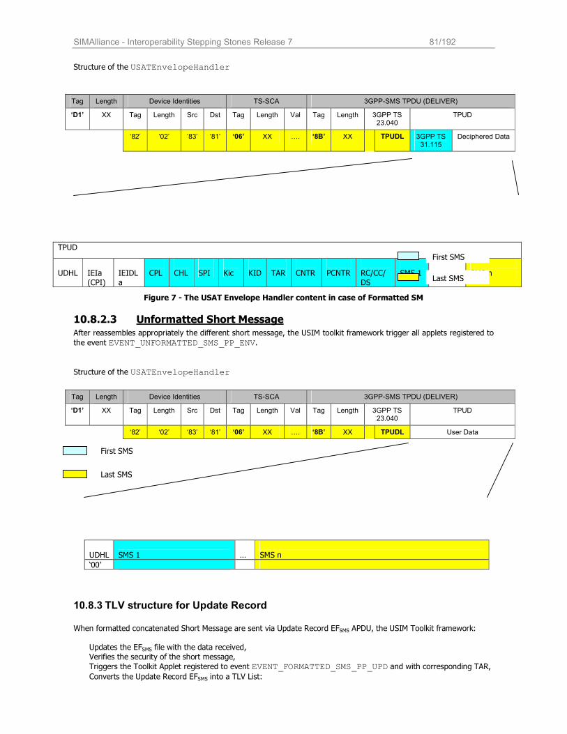
SIMAlliance - Interoperability Stepping Stones Release 7 81/192
Structure of the USATEnvelopeHandler
Figure 7 - The USAT Envelope Handler content in case of Formatted SM
10.8.2.3 Unformatted Short Message After reassembles appropriately the different short message, the USIM toolkit framework trigger all applets registered to
the event EVENT_UNFORMATTED_SMS_PP_ENV.
Structure of the USATEnvelopeHandler
10.8.3 TLV structure for Update Record
When formatted concatenated Short Message are sent via Update Record EFSMS APDU, the USIM Toolkit framework:
Updates the EFSMS file with the data received,
Verifies the security of the short message,
Triggers the Toolkit Applet registered to event EVENT_FORMATTED_SMS_PP_UPD and with corresponding TAR, Converts the Update Record EFSMS into a TLV List:
Tag Length Device Identities TS-SCA 3GPP-SMS TPDU (DELIVER)
‘D1’ XX Tag Length Src Dst Tag Length Val Tag Length 3GPP TS 23.040
TPUD
‘82’ ‘02’ ‘83’ ‘81’ ‘06’ XX …. ‘8B’ XX TPUDL 3GPP TS 31.115
Deciphered Data
TPUD
UDHL
IEIa (CPI)
IEIDLa
CPL
CHL
SPI
Kic
KID
TAR
CNTR
PCNTR
RC/CC/DS
SMS 1
…
SMS n
Tag Length Device Identities TS-SCA 3GPP-SMS TPDU (DELIVER)
‘D1’ XX Tag Length Src Dst Tag Length Val Tag Length 3GPP TS 23.040
TPUD
‘82’ ‘02’ ‘83’ ‘81’ ‘06’ XX …. ‘8B’ XX TPUDL User Data
UDHL
SMS 1
…
SMS n
‘00’
First SMS
Last SMS
First SMS
Last SMS
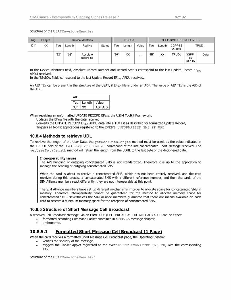
SIMAlliance - Interoperability Stepping Stones Release 7 82/192
Structure of the USATEnvelopeHandler
Tag Length Device Identities TS-SCA 3GPP SMS TPDU (DELIVER)
‘D1’ XX Tag Length Rcd No Status Tag Length Value Tag Length 3GPPTS23.040
TPUD
‘82’ ‘02’ Absolute record nb
‘86’ XX …. ‘8B’ XX TPUDL 3GPP TS
31.115
Data
In the Device Identities field, Absolute Record Number and Record Status correspond to the last Update Record EFSMS APDU received. In the TS-SCA, fields correspond to the last Update Record EFSMS APDU received. An AID TLV can be present in the structure of the USAT, if EFSMS file is under an ADF. The value of AID TLV is the AID of the ADF.
AID
Tag Length Value
‘AF’ XX ADF AID
When receiving an unformatted UPDATE RECORD EFSMS, the USIM Toolkit Framework:
Updates the EFSMS file with the data received; Converts the UPDATE RECORD EFSMS APDU data into a TLV list as described for formatted Update Record,
Triggers all toolkit applications registered to the EVENT_UNFORMATTED_SMS_PP_UPD.
10.8.4 Methods to retrieve UDL
To retrieve the length of the User Data, the getUserDataLength method must be used, as the value indicated in
the TP-UDL field of the USAT EnvelopeHandler correspond at the last concatenated Short Message received. The
getUserDataLength method will return the length from the UDHL to the last byte of the deciphered data.
Interoperability issues The API handling of outgoing concatenated SMS is not standardized. Therefore it is up to the application to manage the sending of outgoing concatenated SMS. When the card is about to receive a concatenated SMS, which has not been entirely received, and the card receives during this process a concatenated SMS with a different reference number, and then the cards of the SIM Alliance members react differently, they are not interoperable at this point.
The SIM Alliance members have set up different mechanisms in order to allocate space for concatenated SMS in memory. Therefore interoperability cannot be guaranteed for the method to allocate memory space for
concatenated SMS. Nevertheless the SIM Alliance members guarantee that there are means available on each card to reserve a minimum memory space for the reception of concatenated SMS.
10.8.5 Structure of Short Message Cell Broadcast
A received Cell Broadcast Message, via an ENVELOPE (CELL BROADCAST DOWNLOAD) APDU can be either:
• formatted according Command Packet contained in a SMS-CB message chapter, • unformatted.
10.8.5.1 Formatted Short Message Cell Broadcast (1 Page) When the card receives a formatted Short Message Cell Broadcast page, the Operating System:
• verifies the security of the message,
• triggers the Toolkit Applet registered to the event EVENT_FORMATTED_SMS_CB, with the corresponding TAR.
Structure of the USATEnvelopeHandler:
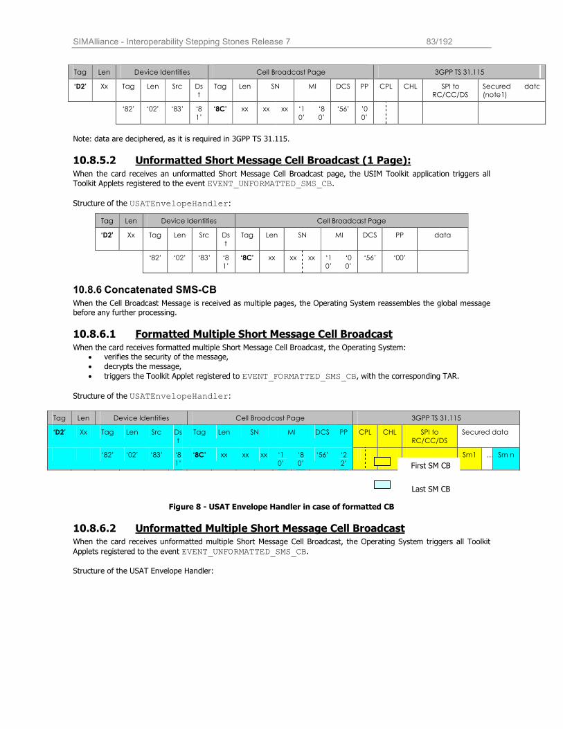
SIMAlliance - Interoperability Stepping Stones Release 7 83/192
Note: data are deciphered, as it is required in 3GPP TS 31.115.
10.8.5.2 Unformatted Short Message Cell Broadcast (1 Page):
When the card receives an unformatted Short Message Cell Broadcast page, the USIM Toolkit application triggers all
Toolkit Applets registered to the event EVENT_UNFORMATTED_SMS_CB.
Structure of the USATEnvelopeHandler:
10.8.6 Concatenated SMS-CB
When the Cell Broadcast Message is received as multiple pages, the Operating System reassembles the global message before any further processing.
10.8.6.1 Formatted Multiple Short Message Cell Broadcast When the card receives formatted multiple Short Message Cell Broadcast, the Operating System:
• verifies the security of the message,
• decrypts the message,
• triggers the Toolkit Applet registered to EVENT_FORMATTED_SMS_CB, with the corresponding TAR.
Structure of the USATEnvelopeHandler:
Figure 8 - USAT Envelope Handler in case of formatted CB
10.8.6.2 Unformatted Multiple Short Message Cell Broadcast When the card receives unformatted multiple Short Message Cell Broadcast, the Operating System triggers all Toolkit
Applets registered to the event EVENT_UNFORMATTED_SMS_CB. Structure of the USAT Envelope Handler:
Tag Len Device Identities Cell Broadcast Page 3GPP TS 31.115
‘D2’ Xx Tag Len Src Ds
t
Tag Len SN MI DCS PP CPL CHL SPI to
RC/CC/DS
Secured data
(note1)
‘82’ ‘02’ ‘83’ ‘8
1’
‘8C’ xx xx xx ‘1
0’
‘8
0’
‘56’ ’0
0’
Tag Len Device Identities Cell Broadcast Page
‘D2’ Xx Tag Len Src Ds
t
Tag Len SN MI DCS PP data
‘82’ ‘02’ ‘83’ ‘8
1’
‘8C’ xx xx xx ‘1
0’
‘0
0’
‘56’ ‘00’
Tag Len Device Identities Cell Broadcast Page 3GPP TS 31.115
‘D2’ Xx Tag Len Src Ds
t
Tag Len SN MI DCS PP CPL CHL SPI to
RC/CC/DS
Secured data
‘82’ ‘02’ ‘83’ ‘8
1’
‘8C’ xx xx xx ‘1
0’
‘8
0’
‘56’ ‘2
2’
Sm1 … Sm n
First SM CB
Last SM CB
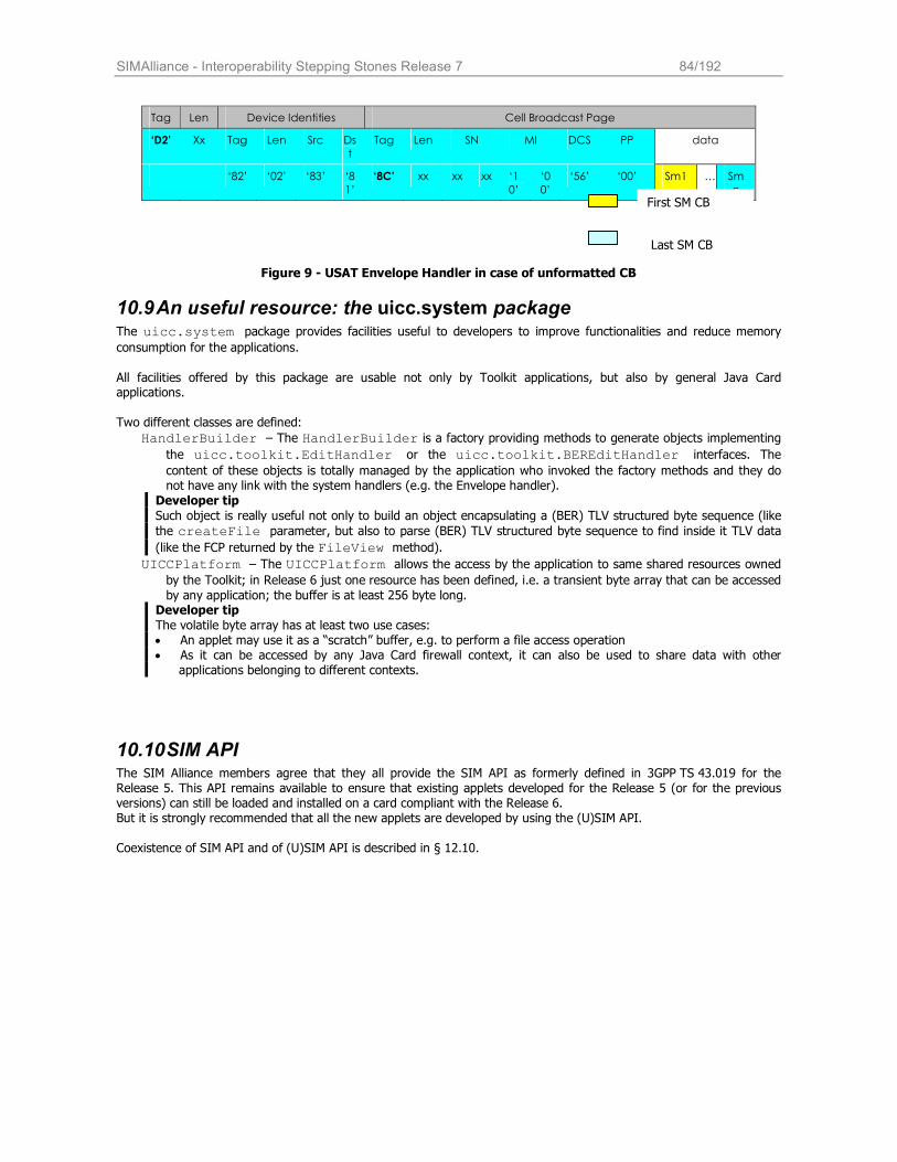
SIMAlliance - Interoperability Stepping Stones Release 7 84/192
Figure 9 - USAT Envelope Handler in case of unformatted CB
10.9 An useful resource: the uicc.system package The uicc.system package provides facilities useful to developers to improve functionalities and reduce memory consumption for the applications.
All facilities offered by this package are usable not only by Toolkit applications, but also by general Java Card applications.
Two different classes are defined:
HandlerBuilder – The HandlerBuilder is a factory providing methods to generate objects implementing
the uicc.toolkit.EditHandler or the uicc.toolkit.BEREditHandler interfaces. The
content of these objects is totally managed by the application who invoked the factory methods and they do not have any link with the system handlers (e.g. the Envelope handler).
Developer tip
Such object is really useful not only to build an object encapsulating a (BER) TLV structured byte sequence (like
the createFile parameter, but also to parse (BER) TLV structured byte sequence to find inside it TLV data
(like the FCP returned by the FileView method).
UICCPlatform – The UICCPlatform allows the access by the application to same shared resources owned by the Toolkit; in Release 6 just one resource has been defined, i.e. a transient byte array that can be accessed
by any application; the buffer is at least 256 byte long. Developer tip
The volatile byte array has at least two use cases: • An applet may use it as a “scratch” buffer, e.g. to perform a file access operation • As it can be accessed by any Java Card firewall context, it can also be used to share data with other
applications belonging to different contexts.
10.10 SIM API The SIM Alliance members agree that they all provide the SIM API as formerly defined in 3GPP TS 43.019 for the Release 5. This API remains available to ensure that existing applets developed for the Release 5 (or for the previous versions) can still be loaded and installed on a card compliant with the Release 6. But it is strongly recommended that all the new applets are developed by using the (U)SIM API. Coexistence of SIM API and of (U)SIM API is described in § 12.10.
Tag Len Device Identities Cell Broadcast Page
‘D2’ Xx Tag Len Src Ds
t
Tag Len SN MI DCS PP data
‘82’ ‘02’ ‘83’ ‘8
1’
‘8C’ xx xx xx ‘1
0’
‘0
0’
‘56’ ‘00’ Sm1 … Sm
n First SM CB
Last SM CB
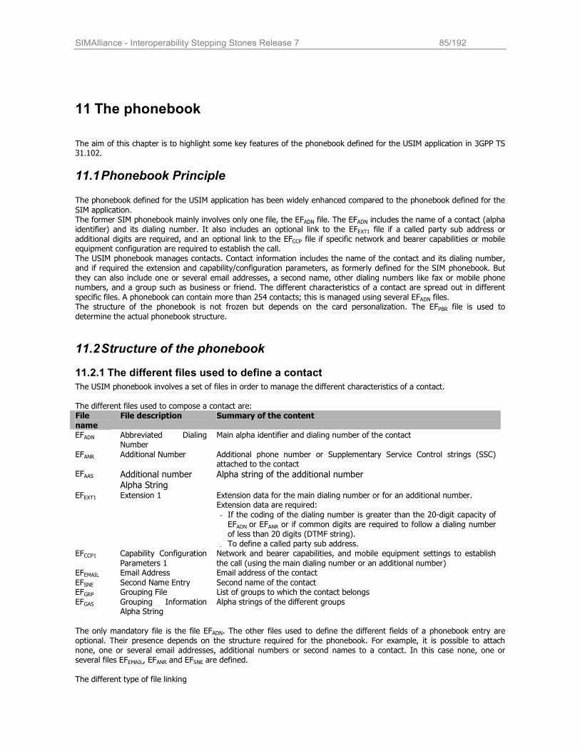
SIMAlliance - Interoperability Stepping Stones Release 7 85/192
11 The phonebook
The aim of this chapter is to highlight some key features of the phonebook defined for the USIM application in 3GPP TS 31.102.
11.1 Phonebook Principle The phonebook defined for the USIM application has been widely enhanced compared to the phonebook defined for the
SIM application. The former SIM phonebook mainly involves only one file, the EFADN file. The EFADN includes the name of a contact (alpha identifier) and its dialing number. It also includes an optional link to the EFEXT1 file if a called party sub address or additional digits are required, and an optional link to the EFCCP file if specific network and bearer capabilities or mobile equipment configuration are required to establish the call. The USIM phonebook manages contacts. Contact information includes the name of the contact and its dialing number, and if required the extension and capability/configuration parameters, as formerly defined for the SIM phonebook. But
they can also include one or several email addresses, a second name, other dialing numbers like fax or mobile phone numbers, and a group such as business or friend. The different characteristics of a contact are spread out in different
specific files. A phonebook can contain more than 254 contacts; this is managed using several EFADN files. The structure of the phonebook is not frozen but depends on the card personalization. The EFPBR file is used to
determine the actual phonebook structure.
11.2 Structure of the phonebook
11.2.1 The different files used to define a contact
The USIM phonebook involves a set of files in order to manage the different characteristics of a contact. The different files used to compose a contact are: File name
File description Summary of the content
EFADN Abbreviated Dialing Number
Main alpha identifier and dialing number of the contact
EFANR Additional Number Additional phone number or Supplementary Service Control strings (SSC) attached to the contact
EFAAS Additional number Alpha String
Alpha string of the additional number
EFEXT1 Extension 1 Extension data for the main dialing number or for an additional number. Extension data are required:
- If the coding of the dialing number is greater than the 20-digit capacity of EFADN or EFANR or if common digits are required to follow a dialing number of less than 20 digits (DTMF string).
- To define a called party sub address. EFCCP1 Capability Configuration
Parameters 1
Network and bearer capabilities, and mobile equipment settings to establish
the call (using the main dialing number or an additional number) EFEMAIL Email Address Email address of the contact
EFSNE Second Name Entry Second name of the contact EFGRP Grouping File List of groups to which the contact belongs
EFGAS Grouping Information Alpha String
Alpha strings of the different groups
The only mandatory file is the file EFADN. The other files used to define the different fields of a phonebook entry are optional. Their presence depends on the structure required for the phonebook. For example, it is possible to attach none, one or several email addresses, additional numbers or second names to a contact. In this case none, one or several files EFEMAIL, EFANR and EFSNE are defined. The different type of file linking
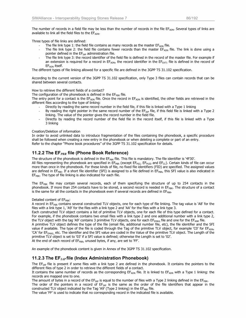
SIMAlliance - Interoperability Stepping Stones Release 7 86/192
The number of records in a field file may be less than the number of records in the file EFADN. Several types of links are
available to link all the field files to the EFADN.
Three types of file links are defined: - The file link type 1: the field file contains as many records as the master EFADN file. - The file link type 2: the field file contains fewer records than the master EFADN file. The link is done using a
pointer defined in the EFIAP administration file. - The file link type 3: the record identifier of the field file is defined in the record of the master file. For example if
an extension is required for a record in EFADN, the record identifier in the EFEXT1 file is defined in the record of EFADN itself.
The different types of file linking allowed for a specific file are defined in the 3GPP TS 31.102 specification.
According to the current version of the 3GPP TS 31.102 specification, only Type 3 files can contain records that can be shared between several contacts. How to retrieve the different fields of a contact? The configuration of the phonebook is defined in the EFPBR file. The entry point for a contact is the EFADN file. Once the record in EFADN is identified, the other fields are retrieved in the different files according to the type of linking:
- Directly by reading the same record number in the field file, if this file is linked with a Type 1 linking - By reading the right pointer in the same record number of the EFIAP file, if this field file is linked with a Type 2
linking. The value of the pointer gives the record number in the field file.
- Directly by reading the record number of the field file in the record itself, if this file is linked with a Type 3 linking
Creation/Deletion of information In order to avoid unlinked data to introduce fragmentation of the files containing the phonebook, a specific procedure shall be followed when creating a new entry in the phonebook or when deleting a complete or part of an entry. Refer to the chapter “Phone book procedures” of the 3GPP TS 31.102 specification for details.
11.2.2 The EFPBR file (Phone Book Reference)
The structure of the phonebook is defined in the EFPBR file. This file is mandatory. The file identifier is ‘4F30’.
All files representing the phonebook are specified in EFPBR (except EFPSC, EFPUID and EFCC). Certain kinds of file can occur more than once in the phonebook. For these kinds of file, no fixed file identifiers (FID) are specified. The assigned values
are defined in EFPBR. If a short file identifier (SFI) is assigned to a file defined in EFPBR, this SFI value is also indicated in EFPBR. The type of file linking is also indicated for each file.
The EFPBR file may contain several records, each of them specifying the structure of up to 254 contacts in the phonebook. If more than 254 contacts have to be stored, a second record is needed in EFPBR. The structure of a contact is the same for all the contacts in the phonebook even if several records are defined in EFPBR. Detailed content of EFPBR: A record in EFPBR contains several constructed TLV objects, one for each type of file linking. The tag value is ‘A8’ for the files with a link type 1, ‘A9’ for the files with a link type 2 and ‘AA’ for the files with a link type 3.
Each constructed TLV object contains a list of primitive TLV objects, one for each file of this type defined for a contact. For example, if the phonebook contains two email files with a link type 2 and one additional number with a link type 2, the TLV object with the tag ‘A9’ contains 3 primitive TLV objects, one for each EFEMAIL file and one for the EFANR file. A primitive TLV object defines the type of the file (email file, additional number file, etc), the file identifier and the SFI value if available. The type of the file is coded through the Tag of the primitive TLV object, for example ‘C0’ for EFADN, ‘CA’ for EFEMAIL, etc. The identifier and the SFI value are coded in the Value of the primitive TLV object. The Length of the primitive TLV object is set to ‘03’ if a SFI value is defined; otherwise the Length is set to ‘02’.
At the end of each record of EFPBR, unused bytes, if any, are set to ‘FF’.
An example of the phonebook content is given in Annex of the 3GPP TS 31.102 specification.
11.2.3 The EFIAP file (Index Administration Phonebook)
The EFIAP file is present if some files with a link type 2 are defined in the phonebook. It contains the pointers to the different files of type 2 in order to retrieve the different fields of a contact.
It contains the same number of records as the corresponding EFADN file. It is linked to EFADN with a Type 1 linking: the records are mapped one to one. The amount of bytes in a record of the EFIAP is equal to the number of files with a Type 2 linking defined in the EFPBR. The order of the pointers in a record of EFIAP is the same as the order of the file identifiers that appear in the constructed TLV object indicated by the Tag ‘A9’ (Type 2 linking) in the EFPBR file. The value ‘FF’ is used to indicate that no corresponding record in the indicated file is available.
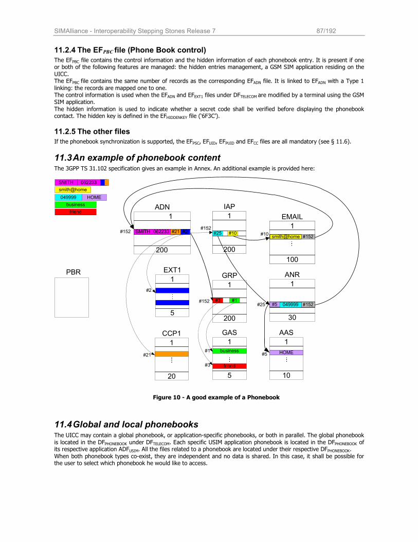
SIMAlliance - Interoperability Stepping Stones Release 7 87/192
11.2.4 The EFPBC file (Phone Book control)
The EFPBC file contains the control information and the hidden information of each phonebook entry. It is present if one or both of the following features are managed: the hidden entries management, a GSM SIM application residing on the
UICC. The EFPBC file contains the same number of records as the corresponding EFADN file. It is linked to EFADN with a Type 1
linking: the records are mapped one to one. The control information is used when the EFADN and EFEXT1 files under DFTELECOM are modified by a terminal using the GSM SIM application.
The hidden information is used to indicate whether a secret code shall be verified before displaying the phonebook contact. The hidden key is defined in the EFHIDDENKEY file (‘6F3C’).
11.2.5 The other files
If the phonebook synchronization is supported, the EFPSC, EFUID, EFPUID and EFCC files are all mandatory (see § 11.6).
11.3 An example of phonebook content The 3GPP TS 31.102 specification gives an example in Annex. An additional example is provided here:
ADN
ANR
EMAIL1
200
1
30
1
100
GRP
1
200
IAP
1
200
GAS
1
5
AAS
1
10
#3
HOMEbusiness
friend
#1
EXT1
1
5
#2 #25 #10
#5
CCP1
1
20
#21#152
#152
PBR
#10
#25
#5
#152#152
#152
#2
#21
#3
#1
SMITH 062233smith@home
049999
SMITH 062233
smith@home
049999 HOME
business
friend
Figure 10 - A good example of a Phonebook
11.4 Global and local phonebooks The UICC may contain a global phonebook, or application-specific phonebooks, or both in parallel. The global phonebook
is located in the DFPHONEBOOK under DFTELECOM. Each specific USIM application phonebook is located in the DFPHONEBOOK of its respective application ADFUSIM. All the files related to a phonebook are located under their respective DFPHONEBOOK.
When both phonebook types co-exist, they are independent and no data is shared. In this case, it shall be possible for the user to select which phonebook he would like to access.
SIMAlliance - Interoperability Stepping Stones Release 7 88/192
11.5 Link with the GSM SIM phonebook If a GSM SIM application resides on the UICC, the EFADN and EFEXT1 files from one DFPHONEBOOK are mapped to the EFADN and EFEXT1 files of the DFTELECOM. Their file IDs are specified in 3GPP TS 51.011, i.e. EFADN = '6F3A' and EFEXT1 = '6F4A',
respectively. Only the first 254 contacts can be mapped.
Synchronization between the 2G phonebook and the 3G phonebook If the UICC is inserted into a terminal accessing the EFADN and EFEXT1 files under DFTELECOM and a record of these files has
been updated, a flag in the corresponding entry control information in the EFPBC under DFPHONEBOOK is set from 0 to 1 by the UICC. If the UICC is later inserted into a terminal that supports the 3G phonebook, the terminal shall check the flag in EFPBC and if this flag is set, update the EFCC, and then reset the flag. A flag set in EFPBC results in a full synchronization of the phonebook between an external entity and the UICC (when synchronization is requested).
11.6 Phonebook synchronization To support synchronization of phonebook contacts with other devices, the USIM may provide the following files: a phonebook synchronization counter (PSC), a unique identifier (UID) and a change counter (CC) to indicate recent changes. If synchronization is supported in the phonebook, then EFPSC, EFUID, EFPUID and EFCC are all mandatory. All these files are used to keep track of the updates/deletions in an existing phonebook entry. It is also possible to
update the phonebook in different terminals, which are still able to detect the changes (e.g. changes between different handset and/or 2nd and 3rd generation of terminals).
Refer to the chapter “Phone book Synchronization” of the 3GPP TS 31.102 specification for further details.
SIMAlliance - Interoperability Stepping Stones Release 7 89/192
12 Interworking between SIM and USIM applications
A SIM application and a USIM application, which are implemented together on a unique UICC, can never be active at the same time. It is also impossible to switch from one to the other during a session (selection of the application depends
depend on the ME (2G or 3G). Applications (SIM/USIM) have to be virtually independent from a functional point of view. However, both applications may share certain objects to optimize memory consumption.
12.1 IMSI, secret key and authentication algorithm A single subscription is identified by many elements:
• A particular IMSI (IMSI 2G = IMSI 3G) • A particular secret key (Ki for 2G or K for 3G, where Ki can be equal to K)
• A particular type of authentication algorithm (“A3/A8” for 2G or “f1-f5” for 3G). A particularity, that is valid for 2G and 3G contexts, is that a single IMSI can never be connected to more than one secret key or algorithm.
There are three possible options for the UICC:
• Separate IMSI & Separate Secret Key: This case applies if the network operator wants to administrate the 2G and the 3G subscription (i.e. the usage of a 2G and 3G ME, fully independent). Consequences are that USIM and SIM applications have to keep separate IMSIs and also their own authentication algorithm. (see 3GPP TR 31 900 Annex B and 3GPP TS 31 102). • Separate IMSI & Shared Secret Key:
From a functional point of view, it is similar to the previous option, except that the UICC saves 128 bits for the storage of a second secret key. • Shared IMSI & Shared Secret Key:
This option is valid when the network operator wants to have a single subscription for a user (independently of the ME (2G/3G)). IMSIs and secret keys are identical for SIM application and USIM
application.
12.2 Secret codes For the SIM application, only CHV1 and CHV2, are available. They apply to files situated in DF-GSM and DF-TELECOM. For the USIM application, up to 8 Application PINs with global key references may be available. The UICC can also support up to 8 Local PINs with specific key references. Further, up to 10 administrative PINs can be defined. (see ETSI
TS 102 221 §9.4) Local PINs can be used within the MF or within any ADF or DF. A replacement PIN, called Universal PIN, may also exist. Mapping of PINs between 2G and 3G operations mode like enabling, disabling or changing of a PIN in one operation mode impacts the other operation mode.
Interoperability issue
SIM Alliance members cannot guarantee Local PIN availability under the MF.
12.3 Mapping of CHV1 CHV1 in the SIM application can be mapped to any USIM application PIN with a global key reference, but only one at a time. When the UICC is single verification capable, CHV1 is mapped to USIM application PIN. If the USIM application PIN is disabled, CHV1 is also disabled. (see 3GPP TR 31 900 Annex D1)
12.4 Mapping of CHV2 CHV2 (SIM application) can be mapped to the corresponding local key reference belonging to the USIM application to which CHV1 is mapped. Regarding to the requirements in TS 11.11 and TS 51.011 for CHV2, this PIN cannot be disabled in either operation mode. In that case, the UICC will return an appropriate error condition.
SIMAlliance - Interoperability Stepping Stones Release 7 90/192
12.5 Mapping of Local PINs A SIM does not support Local PINs.
12.6 Mapping of administrative PINs The mapping of administrative PINs between 2G and 3G operation modes is fully under the discretion of each network operator and card manufacturer.
12.7 Access condition In case an EF or DF is accessible in SIM application and USIM application, independent 2G or 3G access condition can be
defined for this file. If necessary, it is the responsibility of the network operator and the card manufacturer that the security attributes for 2G and 3G sessions are consistent.
12.8 Access to file system for 2G / 3G applets
12.8.1 Definitions
There are two definitions of file system:
• The UICC Shared File System application shall have access only to files situated under the MF (DFs
and EFs files). ADFs are not considered to be files under the MF. • USIM File System allows access to DFs and EFs located under ADFs.
In this document, 2G applets correspond to applets using Release 5 APIs. For access file rules, theses applets will use
sim.access package. The sim.access can only access to the UICC Shared File System by using the SIMView interface.
3G applets correspond to applets using Release 6 APIs. For access file rules, these applets will use uicc.access or
usim.access package. The uicc.access can access the whole file system (see § Error! Reference source not found.)
12.8.2 Accessibility table
The different ways to access file system by each file context is explain in the following table:
12.9 Activation of SIM and USIM applications After a cold reset, no particular application is active on the UICC. The ME selects the right NAA (SIM or USIM application) according to its capabilities. A 3G or 2G/3G dual mode ME or a 2G ME of R99 or Rel-4 with USIM support or a 2G ME of Rel-5 will only send commands with class byte = '0X' or '8X' and will explicitly select the USIM application. A 2G ME of Rel-4 (or earlier) without USIM support will only send commands with class byte = 'A0' and then implicitly select the SIM application. The application selection takes place regardless of the result of the command (i.e. command successful or not). In case a USIM session has been activated, it excludes the possibility to activate a SIM session. In particular, this implies
that once a USIM application is activated, all commands sent to the USIM with “CLA = 0xA0” shall return, to the terminal, the Status Words “0x6E00” (class not supported). A toolkit applet can be triggered whatever SIM or USIM application is the current NAA. Applets can access to any ADF independently from the current NAA and from the current card session.
12.10 SIM and USIM APIs interworking It’s declared as not specified, and so it is not interoperable, applet behavior in case of usage of both SIM APIs and USIM
APIs.
Accessing files under MF Accessing files under a specific ADF
File Access Yes No
Package JavaCard sim.access None 2G Applet
Access Condition 2G None
File Access Yes Yes
Package JavaCard uicc.access uicc.access 3G Applet
Access Condition 3G 3G
SIMAlliance - Interoperability Stepping Stones Release 7 91/192
It is recommended to develop application by using USIM APIs also in case of 2G functionalities, in order to take
advantage of all the enhanced features of the USIM APIs.
12.10.1 Terminal Profile
The terminal profile info provided by the ME are given to 2G applet in the MEProfile object and to the 3G applets in
the TerminalProfile object. Both objects have the same content. As many features have been made mandatory for 3G ME, the relevant bits in the Terminal Profile are set to 1 in 102 223. When a 3G card is inserted in a 2G terminal, the bit verification of these features should be checked according to
51.014 also by 3G applets.
12.10.2 Triggering and Registration
The 2G applets and the 3G applets are not triggered on the same “Toolkit Interface”. The SAT ones are triggered on
sim.toolkit.ToolkitInterface. The USAT applets are triggered on
uicc.toolkit.ToolkitInterface. The triggering order for applets will only depends on the priority level defined during the loading stage of the applet, independently of the applet type. When a USIM is the current application or when there is no application selected, the SIM Toolkit Framework generates
events based on APDUs defined in TS 102 221 and TS 31.102 in order to trigger an applet.
Example ENVELOPE (MENU SELECTION) defined in TS 102 223 with class byte 0x80 should trigger SAT applets registered to EVENT_SELECTION_MENU).
2G and 3G applets share the same card resources.
Example
As an example, if a USAT applet is registered to Call Control, an applet using SIM API can not be registered on Call Control. Moreover, if a Timer is allocated with a SIM API, it can not be allocated with a USIM API.
12.10.3 System handlers and proactive commands
The EnvelopeResponseHandler is available for all triggered applets (SAT and USAT) when available for the event. An envelope response or a sent proactive command, using specific applet API, has to be posted by the applet.
Also, the ProactiveHandler may not be available, for SAT and USAT applets, if a proactive command is pending (see TS 43.019, TS 102 241 and TS 31.130).
Note The system proactive commands generated by the Toolkit Framework are independent of the current NAA.
The only exception is identified for the SET UP MENU proactive command. In fact two EFSUME files can be created (one under DFGSM and one under DFTELECOM) and can be different (alpha and icon identifiers). The Toolkit Framework generates the same SET UP MENU proactive command if files are mapped (see § Error! Reference source not found.)
12.10.4 Behaviours of SIM API used in a 3G mode
Developer tip SAT Applets can access to the functions and data described in TS 51.011 and TS 11.14, if the current application is the SIM one.
New features defined for proactive commands in TS 31.111 are not available for SAT applets. Moreover, new events introduced in UICC/USAT API are not available for SAT applets (e.g.
EVENT_DOWNLOAD_DISPLAY_PARAMETER_CHANGE, EVENT_EXTERNAL_FILE_UPDATE).
12.11 Behaviours of USIM API used in 2G mode There is no restriction concerning USIM API in 2G mode as they were designed in the interworking view.
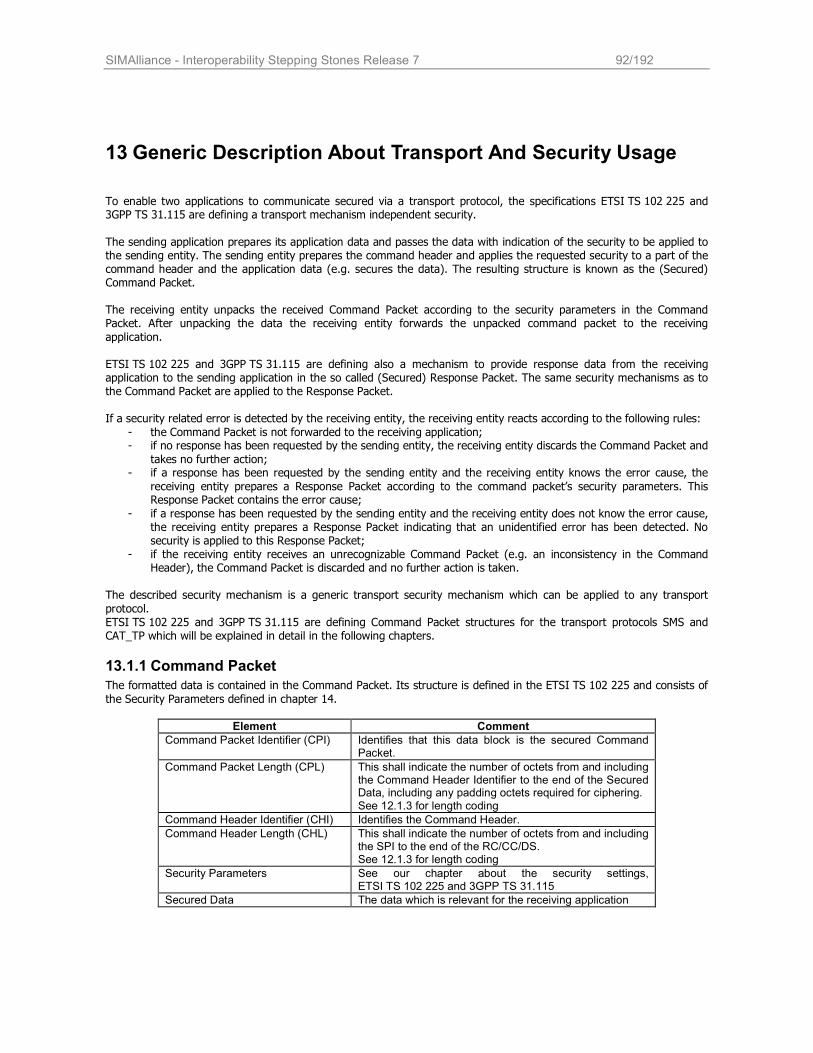
SIMAlliance - Interoperability Stepping Stones Release 7 92/192
13 Generic Description About Transport And Security Usage
To enable two applications to communicate secured via a transport protocol, the specifications ETSI TS 102 225 and 3GPP TS 31.115 are defining a transport mechanism independent security.
The sending application prepares its application data and passes the data with indication of the security to be applied to the sending entity. The sending entity prepares the command header and applies the requested security to a part of the command header and the application data (e.g. secures the data). The resulting structure is known as the (Secured) Command Packet. The receiving entity unpacks the received Command Packet according to the security parameters in the Command Packet. After unpacking the data the receiving entity forwards the unpacked command packet to the receiving
application. ETSI TS 102 225 and 3GPP TS 31.115 are defining also a mechanism to provide response data from the receiving application to the sending application in the so called (Secured) Response Packet. The same security mechanisms as to the Command Packet are applied to the Response Packet. If a security related error is detected by the receiving entity, the receiving entity reacts according to the following rules:
- the Command Packet is not forwarded to the receiving application; - if no response has been requested by the sending entity, the receiving entity discards the Command Packet and
takes no further action; - if a response has been requested by the sending entity and the receiving entity knows the error cause, the
receiving entity prepares a Response Packet according to the command packet’s security parameters. This Response Packet contains the error cause;
- if a response has been requested by the sending entity and the receiving entity does not know the error cause, the receiving entity prepares a Response Packet indicating that an unidentified error has been detected. No security is applied to this Response Packet;
- if the receiving entity receives an unrecognizable Command Packet (e.g. an inconsistency in the Command Header), the Command Packet is discarded and no further action is taken.
The described security mechanism is a generic transport security mechanism which can be applied to any transport
protocol. ETSI TS 102 225 and 3GPP TS 31.115 are defining Command Packet structures for the transport protocols SMS and CAT_TP which will be explained in detail in the following chapters.
13.1.1 Command Packet
The formatted data is contained in the Command Packet. Its structure is defined in the ETSI TS 102 225 and consists of
the Security Parameters defined in chapter 14.
Element Comment
Command Packet Identifier (CPI) Identifies that this data block is the secured Command Packet.
Command Packet Length (CPL) This shall indicate the number of octets from and including the Command Header Identifier to the end of the Secured Data, including any padding octets required for ciphering. See 12.1.3 for length coding
Command Header Identifier (CHI) Identifies the Command Header.
Command Header Length (CHL) This shall indicate the number of octets from and including the SPI to the end of the RC/CC/DS. See 12.1.3 for length coding
Security Parameters See our chapter about the security settings, ETSI TS 102 225 and 3GPP TS 31.115
Secured Data The data which is relevant for the receiving application
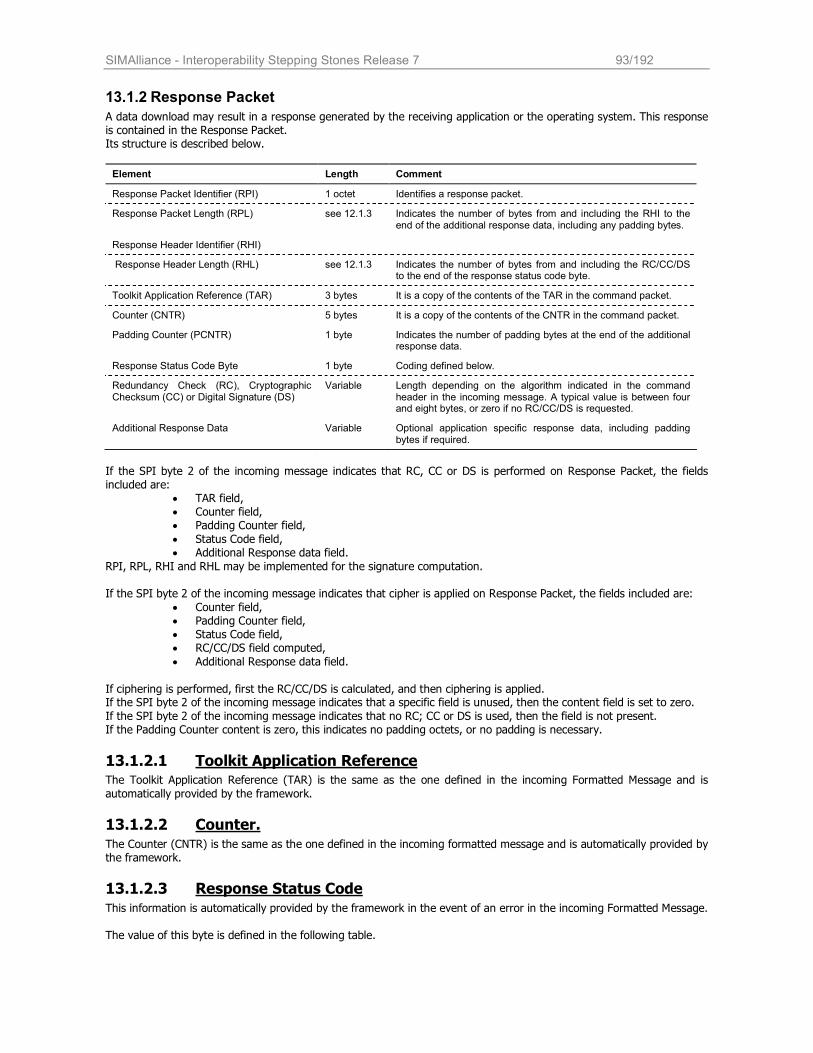
SIMAlliance - Interoperability Stepping Stones Release 7 93/192
13.1.2 Response Packet
A data download may result in a response generated by the receiving application or the operating system. This response is contained in the Response Packet. Its structure is described below.
Element Length Comment
Response Packet Identifier (RPI) 1 octet Identifies a response packet.
Response Packet Length (RPL) see 12.1.3 Indicates the number of bytes from and including the RHI to the end of the additional response data, including any padding bytes.
Response Header Identifier (RHI)
Response Header Length (RHL) see 12.1.3 Indicates the number of bytes from and including the RC/CC/DS to the end of the response status code byte.
Toolkit Application Reference (TAR) 3 bytes It is a copy of the contents of the TAR in the command packet.
Counter (CNTR) 5 bytes It is a copy of the contents of the CNTR in the command packet.
Padding Counter (PCNTR) 1 byte Indicates the number of padding bytes at the end of the additional response data.
Response Status Code Byte 1 byte Coding defined below.
Redundancy Check (RC), Cryptographic Checksum (CC) or Digital Signature (DS)
Variable Length depending on the algorithm indicated in the command header in the incoming message. A typical value is between four and eight bytes, or zero if no RC/CC/DS is requested.
Additional Response Data Variable Optional application specific response data, including padding bytes if required.
If the SPI byte 2 of the incoming message indicates that RC, CC or DS is performed on Response Packet, the fields included are:
• TAR field, • Counter field, • Padding Counter field,
• Status Code field, • Additional Response data field.
RPI, RPL, RHI and RHL may be implemented for the signature computation. If the SPI byte 2 of the incoming message indicates that cipher is applied on Response Packet, the fields included are:
• Counter field, • Padding Counter field, • Status Code field, • RC/CC/DS field computed,
• Additional Response data field.
If ciphering is performed, first the RC/CC/DS is calculated, and then ciphering is applied. If the SPI byte 2 of the incoming message indicates that a specific field is unused, then the content field is set to zero.
If the SPI byte 2 of the incoming message indicates that no RC; CC or DS is used, then the field is not present. If the Padding Counter content is zero, this indicates no padding octets, or no padding is necessary.
13.1.2.1 Toolkit Application Reference The Toolkit Application Reference (TAR) is the same as the one defined in the incoming Formatted Message and is
automatically provided by the framework.
13.1.2.2 Counter.
The Counter (CNTR) is the same as the one defined in the incoming formatted message and is automatically provided by the framework.
13.1.2.3 Response Status Code
This information is automatically provided by the framework in the event of an error in the incoming Formatted Message. The value of this byte is defined in the following table.
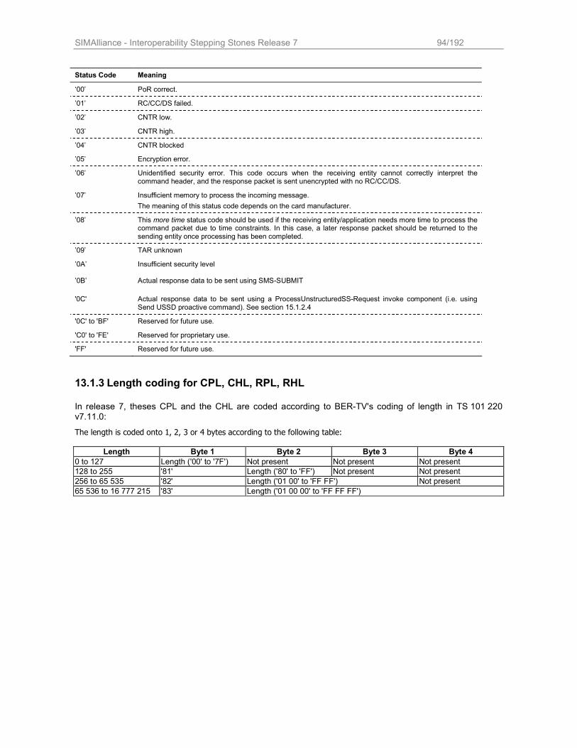
SIMAlliance - Interoperability Stepping Stones Release 7 94/192
13.1.3 Length coding for CPL, CHL, RPL, RHL
In release 7, theses CPL and the CHL are coded according to BER-TV's coding of length in TS 101 220 v7.11.0:
The length is coded onto 1, 2, 3 or 4 bytes according to the following table:
Length Byte 1 Byte 2 Byte 3 Byte 4
0 to 127 Length ('00' to '7F') Not present Not present Not present
128 to 255 '81' Length ('80' to 'FF') Not present Not present
256 to 65 535 '82' Length ('01 00' to 'FF FF') Not present
65 536 to 16 777 215 '83' Length ('01 00 00' to 'FF FF FF')
Status Code Meaning
‘00’ PoR correct.
’01’ RC/CC/DS failed.
’02’ CNTR low.
’03’ CNTR high.
’04’ CNTR blocked
’05’ Encryption error.
’06’ Unidentified security error. This code occurs when the receiving entity cannot correctly interpret the command header, and the response packet is sent unencrypted with no RC/CC/DS.
’07’ Insufficient memory to process the incoming message.
The meaning of this status code depends on the card manufacturer.
’08’ This more time status code should be used if the receiving entity/application needs more time to process the command packet due to time constraints. In this case, a later response packet should be returned to the sending entity once processing has been completed.
’09’ TAR unknown
’0A’ Insufficient security level
’0B’ Actual response data to be sent using SMS-SUBMIT
'0C' Actual response data to be sent using a ProcessUnstructuredSS-Request invoke component (i.e. using Send USSD proactive command). See section 15.1.2.4
'0C' to 'BF' Reserved for future use.
'C0' to 'FE' Reserved for proprietary use.
'FF' Reserved for future use.
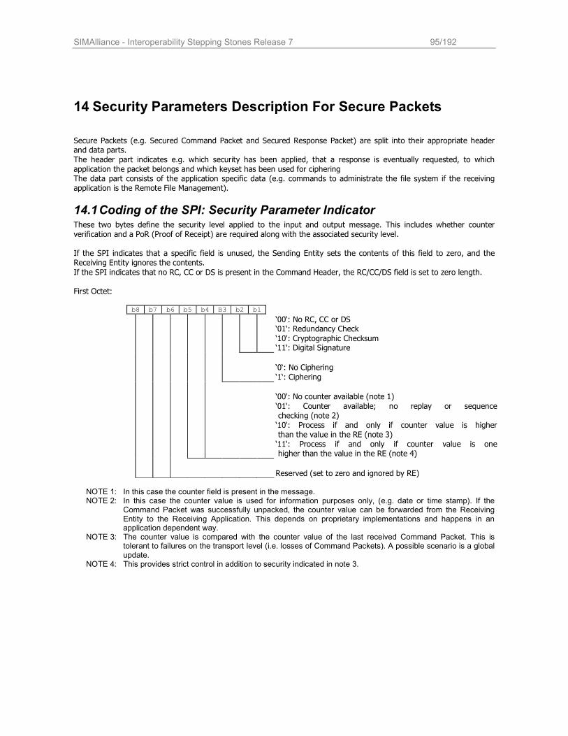
SIMAlliance - Interoperability Stepping Stones Release 7 95/192
14 Security Parameters Description For Secure Packets
Secure Packets (e.g. Secured Command Packet and Secured Response Packet) are split into their appropriate header and data parts.
The header part indicates e.g. which security has been applied, that a response is eventually requested, to which application the packet belongs and which keyset has been used for ciphering The data part consists of the application specific data (e.g. commands to administrate the file system if the receiving application is the Remote File Management).
14.1 Coding of the SPI: Security Parameter Indicator These two bytes define the security level applied to the input and output message. This includes whether counter verification and a PoR (Proof of Receipt) are required along with the associated security level. If the SPI indicates that a specific field is unused, the Sending Entity sets the contents of this field to zero, and the Receiving Entity ignores the contents.
If the SPI indicates that no RC, CC or DS is present in the Command Header, the RC/CC/DS field is set to zero length.
First Octet: b8 b7 b6 b5 b4 B3 b2 b1
‘00‘: No RC, CC or DS ‘01‘: Redundancy Check
‘10‘: Cryptographic Checksum ‘11‘: Digital Signature
‘0‘: No Ciphering
‘1‘: Ciphering
‘00‘: No counter available (note 1)
‘01‘: Counter available; no replay or sequence checking (note 2) ‘10‘: Process if and only if counter value is higher than the value in the RE (note 3) ‘11‘: Process if and only if counter value is one higher than the value in the RE (note 4)
Reserved (set to zero and ignored by RE) NOTE 1: In this case the counter field is present in the message. NOTE 2: In this case the counter value is used for information purposes only, (e.g. date or time stamp). If the
Command Packet was successfully unpacked, the counter value can be forwarded from the Receiving Entity to the Receiving Application. This depends on proprietary implementations and happens in an application dependent way.
NOTE 3: The counter value is compared with the counter value of the last received Command Packet. This is tolerant to failures on the transport level (i.e. losses of Command Packets). A possible scenario is a global update.
NOTE 4: This provides strict control in addition to security indicated in note 3.
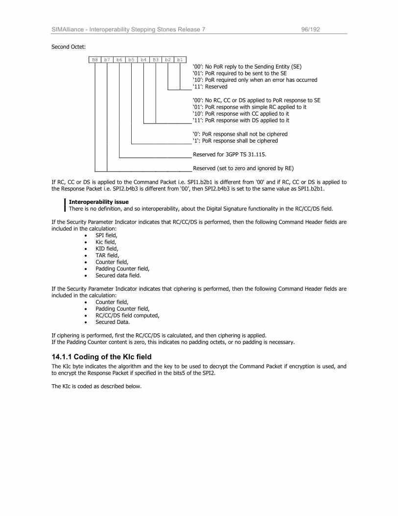
SIMAlliance - Interoperability Stepping Stones Release 7 96/192
Second Octet:
B8 b7 b6 b5 b4 B3 b2 b1
‘00’: No PoR reply to the Sending Entity (SE)
‘01’: PoR required to be sent to the SE ‘10’: PoR required only when an error has occurred
‘11’: Reserved
‘00’: No RC, CC or DS applied to PoR response to SE
‘01’: PoR response with simple RC applied to it ‘10’: PoR response with CC applied to it ‘11’: PoR response with DS applied to it
‘0’: PoR response shall not be ciphered ‘1‘: PoR response shall be ciphered
Reserved for 3GPP TS 31.115.
Reserved (set to zero and ignored by RE)
If RC, CC or DS is applied to the Command Packet i.e. SPI1.b2b1 is different from '00' and if RC, CC or DS is applied to the Response Packet i.e. SPI2.b4b3 is different from ‘00’, then SPI2.b4b3 is set to the same value as SPI1.b2b1.
Interoperability issue
There is no definition, and so interoperability, about the Digital Signature functionality in the RC/CC/DS field. If the Security Parameter Indicator indicates that RC/CC/DS is performed, then the following Command Header fields are included in the calculation:
• SPI field,
• Kic field, • KID field,
• TAR field, • Counter field, • Padding Counter field,
• Secured data field.
If the Security Parameter Indicator indicates that ciphering is performed, then the following Command Header fields are included in the calculation:
• Counter field, • Padding Counter field,
• RC/CC/DS field computed, • Secured Data.
If ciphering is performed, first the RC/CC/DS is calculated, and then ciphering is applied. If the Padding Counter content is zero, this indicates no padding octets, or no padding is necessary.
14.1.1 Coding of the KIc field
The KIc byte indicates the algorithm and the key to be used to decrypt the Command Packet if encryption is used, and to encrypt the Response Packet if specified in the bits5 of the SPI2. The KIc is coded as described below.
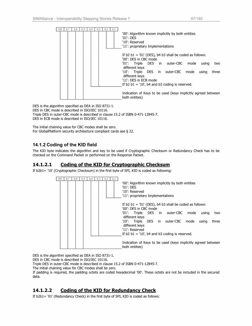
SIMAlliance - Interoperability Stepping Stones Release 7 97/192
B8 b7 b6 b5 b4 b3 b2 b1
‘00‘: Algorithm known implicitly by both entities ‘01‘: DES ‘10‘: Reserved
‘11‘: proprietary Implementations
If b2 b1 = ‘01‘ (DES), b4 b3 shall be coded as follows:
‘00‘: DES in CBC mode ‘01‘: Triple DES in outer-CBC mode using two
different keys ‘10‘: Triple DES in outer-CBC mode using three different keys ‘11‘: DES in ECB mode If b2 b1 = ‘10‘, b4 and b3 coding is reserved.
Indication of Keys to be used (keys implicitly agreed between
both entities)
DES is the algorithm specified as DEA in ISO 8731-1.
DES in CBC mode is described in ISO/IEC 10116. Triple DES in outer-CBC mode is described in clause 15.2 of ISBN 0-471-12845-7. DES in ECB mode is described in ISO/IEC 10116. The initial chaining value for CBC modes shall be zero. For GlobalPlatform security architecture compliant cards see § 22.
14.1.2 Coding of the KID field
The KID byte indicates the algorithm and key to be used if Cryptographic Checksum or Redundancy Check has to be checked on the Command Packet or performed on the Response Packet.
14.1.2.1 Coding of the KID for Cryptographic Checksum
If b2b1= ’10‘ (Cryptographic Checksum) in the first byte of SPI, KID is coded as following: B8 b7 b6 b5 b4 b3 b2 b1
‘00’: Algorithm known implicitly by both entities ‘01’: DES
‘10’: Reserved ‘11’: proprietary Implementations
If b2 b1 = ’01‘ (DES), b4 b3 shall be coded as follows: ‘00’: DES in CBC mode ‘01’: Triple DES in outer-CBC mode using two different keys
‘10’: Triple DES in outer-CBC mode using three different keys
‘11’: Reserved If b2 b1 = ‘10’, b4 and b3 coding is reserved.
Indication of Keys to be used (keys implicitly agreed between both entities)
DES is the algorithm specified as DEA in ISO 8731-1. DES in CBC mode is described in ISO/IEC 10116. Triple DES in outer-CBC mode is described in clause 15.2 of ISBN 0-471-12845-7. The initial chaining value for CBC modes shall be zero.
If padding is required, the padding octets are coded hexadecimal '00'. These octets are not be included in the secured data.
14.1.2.2 Coding of the KID for Redundancy Check If b2b1= ‘01‘ (Redundancy Check) in the first byte of SPI, KID is coded as follows:
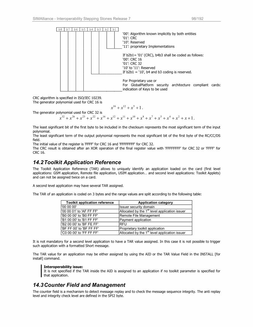
SIMAlliance - Interoperability Stepping Stones Release 7 98/192
b8 b7 b6 b5 b4 b3 b2 b1
‘00’: Algorithm known implicitly by both entities ‘01’: CRC ‘10’: Reserved
‘11’: proprietary Implementations
If b2b1= ‘01’ (CRC), b4b3 shall be coded as follows:
‘00’: CRC 16 ‘01’: CRC 32
‘10’ to ‘11’: Reserved If b2b1 = ‘10’, b4 and b3 coding is reserved.
For Proprietary use or
For GlobalPlatform security architecture compliant cards: indication of Keys to be used
CRC algorithm is specified in ISO/IEC 10239.
The generator polynomial used for CRC 16 is
151216 +++ xxx .
The generator polynomial used for CRC 32 is
1245781011121622232632 ++++++++++++++ xxxxxxxxxxxxxx .
The least significant bit of the first byte to be included in the checksum represents the most significant term of the input polynomial.
The least significant term of the output polynomial represents the most significant bit of the first byte of the RC/CC/DS field.
The initial value of the register is 'FFFF' for CRC 16 and 'FFFFFFFF' for CRC 32. The CRC result is obtained after an XOR operation of the final register value with ‘FFFFFFFF’ for CRC 32 or 'FFFF' for CRC 16.
14.2 Toolkit Application Reference The Toolkit Application Reference (TAR) allows to uniquely identify an application loaded on the card (first level applications: GSM application, Remote file application, USIM application… and second level applications: Toolkit Applets) and can not be assigned twice on a card. A second level application may have several TAR assigned. The TAR of an application is coded on 3 bytes and the range values are split according to the following table:
Toolkit application reference Application category
'00 00 00' Issuer security domain
'00 00 01' to 'AF FF FF' Allocated by the 1st level application issuer
'B0 00 00' to 'B0 FF FF' Remote File Management
'B1 00 00' to 'B1 FF FF' Payment application
'B2 00 00' to 'BF FE FF' RFU
'BF FF 00' to 'BF FF FF' Proprietary toolkit application
'C0 00 00' to 'FF FF FF' Allocated by the 1st level application issuer
It is not mandatory for a second level application to have a TAR value assigned. In this case it is not possible to trigger such application with a formatted Short message. The TAR value for an application may be either assigned by using the AID or the TAR Value Field in the INSTALL [for
install] command.
Interoperability issue: It is not specified if the TAR inside the AID is assigned to an application if no toolkit parameter is specified for
that application.
14.3 Counter Field and Management The counter field is a mechanism to detect message replay and to check the message sequence integrity. The anti replay level and integrity check level are defined in the SPI2 byte.
SIMAlliance - Interoperability Stepping Stones Release 7 99/192
If in the first SPI byte b4b5 = ’00’ (No counter available) the five byte counter must be present in the command packet,
but it is ignored by the RE and the RE does not update the counter.
If b5 of the first SPI byte is equal to ‘1’ then the following rules shall apply to counter management, with the goal of preventing replay and synchronization attacks:
• The SE sets the counter value. It is only incremented. • The RE shall update the counter to its next value upon receipt of a Command Packet after the
corresponding security checks (i.e. RC/CC/DS and CNTR verification) have been passed successfully. • The next counter value is the one received in the incoming message. • When the counter value reaches its maximum value the counter is blocked.
If there is more than one SE, care has to be taken to ensure that the counter values remain synchronized between the SEs to what the RE is expecting, irrespective of the transport mechanism employed. The level of security is indicated via the proprietary interface between the Sending/Receiving Application and Sending/Receiving Entity. Application designers should be aware that if the Sending Application requests "No RC/CC/DS"
or "Redundancy Check" and "No Counter Available" from the SE, no security is applied to the Application Message and therefore there is an increased threat of a malicious attack.
14.4 PCNTR Indicates the number of padding octets used for ciphering at the end of the secured data.
14.5 Secured Data The secured data consists of the application data which has been prepared by the sending or receiving application.
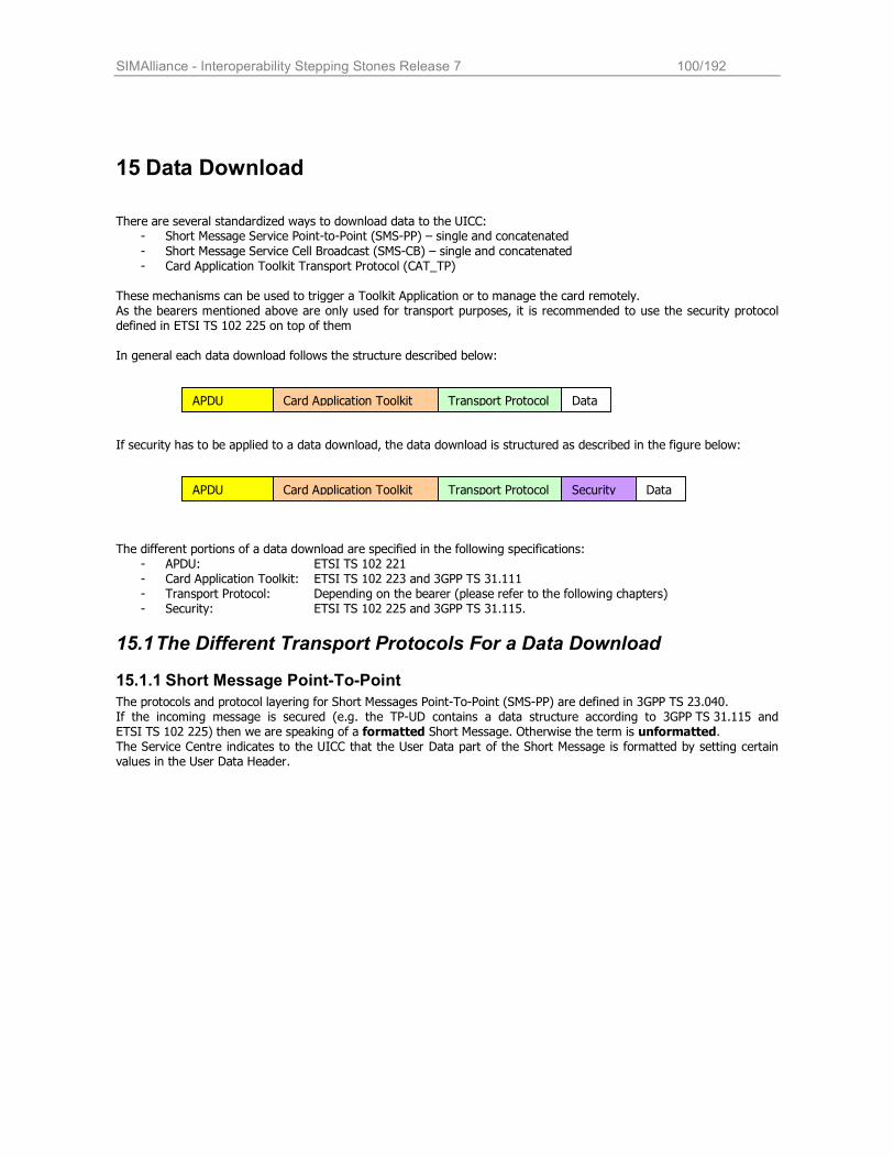
SIMAlliance - Interoperability Stepping Stones Release 7 100/192
15 Data Download
There are several standardized ways to download data to the UICC: - Short Message Service Point-to-Point (SMS-PP) – single and concatenated
- Short Message Service Cell Broadcast (SMS-CB) – single and concatenated - Card Application Toolkit Transport Protocol (CAT_TP)
These mechanisms can be used to trigger a Toolkit Application or to manage the card remotely. As the bearers mentioned above are only used for transport purposes, it is recommended to use the security protocol defined in ETSI TS 102 225 on top of them In general each data download follows the structure described below:
If security has to be applied to a data download, the data download is structured as described in the figure below:
The different portions of a data download are specified in the following specifications:
- APDU: ETSI TS 102 221 - Card Application Toolkit: ETSI TS 102 223 and 3GPP TS 31.111 - Transport Protocol: Depending on the bearer (please refer to the following chapters) - Security: ETSI TS 102 225 and 3GPP TS 31.115.
15.1 The Different Transport Protocols For a Data Download
15.1.1 Short Message Point-To-Point
The protocols and protocol layering for Short Messages Point-To-Point (SMS-PP) are defined in 3GPP TS 23.040. If the incoming message is secured (e.g. the TP-UD contains a data structure according to 3GPP TS 31.115 and ETSI TS 102 225) then we are speaking of a formatted Short Message. Otherwise the term is unformatted. The Service Centre indicates to the UICC that the User Data part of the Short Message is formatted by setting certain values in the User Data Header.
APDU Card Application Toolkit Transport Protocol Security Data
APDU Card Application Toolkit Transport Protocol Data
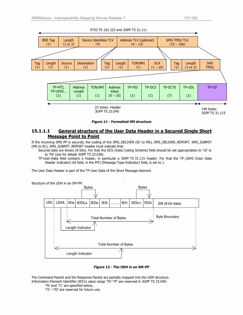
SIMAlliance - Interoperability Stepping Stones Release 7 101/192
Figure 11 - Formatted SM structure
15.1.1.1 General structure of the User Data Header in a Secured Single Short Message Point to Point
If the incoming SMS PP is secured, the coding of the SMS_DELIVER (SC to MS), SMS_DELIVER_REPORT, SMS_SUBMIT
(MS to SC), SMS_SUBMIT_REPORT header must indicate that: Secured data are binary (8 bits). For that the DCS (Data Coding Scheme) field should be set appropriately to ‘16’ or
to ‘F6’ (see for details 3GPP TS 23.038). TP-User-Data field contains a header, in particular a 3GPP TS 31.115 header. For that the TP_UDHI (User Data
Header Indicator) bit field, in the MTI (Message-Type-Indicator) field, is set to 1.
The User Data Header is part of the TP User Data of the Short Message element.
Structure of the UDH in an SM-PP:
U D L U D H L I E I a I E D a I E I b . . . . . . . . . I E I n I E D L n I E D n SM (8-bit data)
Byte Boundary Total Number of Bytes
Length Indicator
Total Number of Bytes
Length Indicator
Bytes Bytes
I E I D L a
Figure 12 - The UDH in an SM-PP
The Command Packet and the Response Packet are partially mapped into the UDH structure. Information Element Identifier (IEI’s) value range ’70’-‘7F’ are reserved in 3GPP TS 23.040:
‘70’ and ‘71’ are specified below, ‘72’ –‘7D’ are reserved for future use,
ETSI TS 102 223 and 3GPP TS 31.111
BER Tag (1)
Length (1 or 2)
Device Identities TLV (4)
Address TLV (optional) (4 – 13)
SMS TPDU TLV (15 – 166)
Tag (1)
Length (1)
Source (1)
Destination (1)
Tag (1)
Length (1)
TON/NPI (1)
SCA (1 – 10)
Tag (1)
Length (1 or 2)
SMS TPDU
TP-MTI, TP-UDHI…
(1)
Address Length
(1)
TON/NPI
(1)
Address Value
(0 – 10)
TP-PID
(1)
TP-DCS
(1)
TP-SCTS
(7)
TP-UDL
(1)
TP-UD
23 bytes: Header 3GPP TS 23.040
140 bytes: 3GPP TS 31.115

SIMAlliance - Interoperability Stepping Stones Release 7 102/192
‘7E’ and ‘7F’ are proprietary implementations.
If Command Packet and Response Packet are too large to be contained in a single Short Message (including the
Command Header or the Response Header), it is concatenated as defined below.
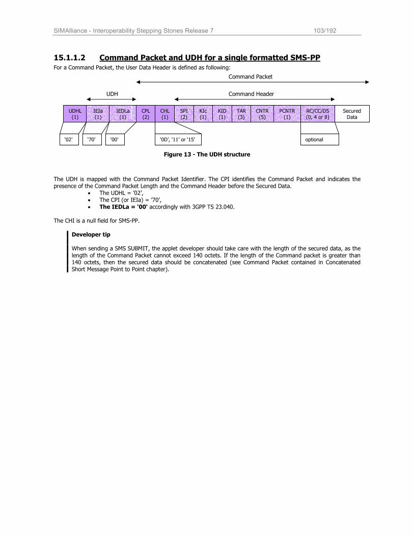
SIMAlliance - Interoperability Stepping Stones Release 7 103/192
15.1.1.2 Command Packet and UDH for a single formatted SMS-PP For a Command Packet, the User Data Header is defined as following:
Figure 13 - The UDH structure
The UDH is mapped with the Command Packet Identifier. The CPI identifies the Command Packet and indicates the presence of the Command Packet Length and the Command Header before the Secured Data.
• The UDHL = ’02’,
• The CPI (or IEIa) = ’70’, • The IEDLa = ‘00‘ accordingly with 3GPP TS 23.040.
The CHI is a null field for SMS-PP.
Developer tip
When sending a SMS SUBMIT, the applet developer should take care with the length of the secured data, as the length of the Command Packet cannot exceed 140 octets. If the length of the Command packet is greater than 140 octets, then the secured data should be concatenated (see Command Packet contained in Concatenated Short Message Point to Point chapter).
UDHL (1)
IEIa (1)
IEDLa (1)
CPL (2)
CHL (1)
SPI (2)
KIc (1)
KID (1)
TAR (3)
CNTR (5)
PCNTR (1)
RC/CC/DS (0, 4 or 8)
Secured Data
UDH Command Header
‘02’ ‘70’ ‘00’ ‘0D’, ‘11’ or ‘15’ optional
Command Packet
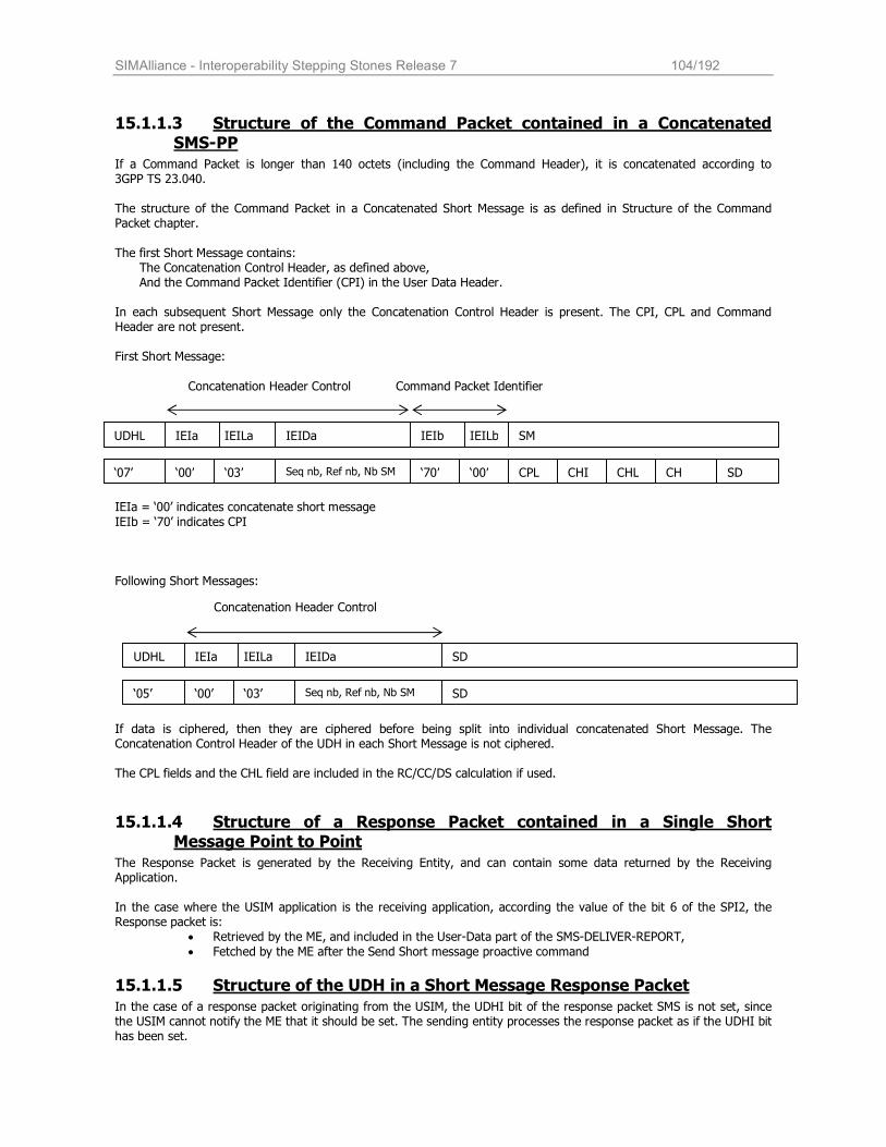
SIMAlliance - Interoperability Stepping Stones Release 7 104/192
15.1.1.3 Structure of the Command Packet contained in a Concatenated SMS-PP
If a Command Packet is longer than 140 octets (including the Command Header), it is concatenated according to 3GPP TS 23.040. The structure of the Command Packet in a Concatenated Short Message is as defined in Structure of the Command Packet chapter.
The first Short Message contains: The Concatenation Control Header, as defined above, And the Command Packet Identifier (CPI) in the User Data Header.
In each subsequent Short Message only the Concatenation Control Header is present. The CPI, CPL and Command Header are not present. First Short Message:
IEIa = ‘00’ indicates concatenate short message
IEIb = ‘70’ indicates CPI
Following Short Messages:
If data is ciphered, then they are ciphered before being split into individual concatenated Short Message. The Concatenation Control Header of the UDH in each Short Message is not ciphered. The CPL fields and the CHL field are included in the RC/CC/DS calculation if used.
15.1.1.4 Structure of a Response Packet contained in a Single Short Message Point to Point
The Response Packet is generated by the Receiving Entity, and can contain some data returned by the Receiving Application. In the case where the USIM application is the receiving application, according the value of the bit 6 of the SPI2, the Response packet is:
• Retrieved by the ME, and included in the User-Data part of the SMS-DELIVER-REPORT,
• Fetched by the ME after the Send Short message proactive command
15.1.1.5 Structure of the UDH in a Short Message Response Packet
In the case of a response packet originating from the USIM, the UDHI bit of the response packet SMS is not set, since the USIM cannot notify the ME that it should be set. The sending entity processes the response packet as if the UDHI bit has been set.
IEILb IEILa UDHL IEIa IEIDa IEIb SM
Concatenation Header Control Command Packet Identifier
‘07’ ‘00’ ‘03’ Seq nb, Ref nb, Nb SM ‘70’ ‘00’ CPL CHI CHL CH SD
IEILa UDHL IEIa IEIDa SD
Concatenation Header Control
‘05’ ‘00’ ‘03’ Seq nb, Ref nb, Nb SM SD
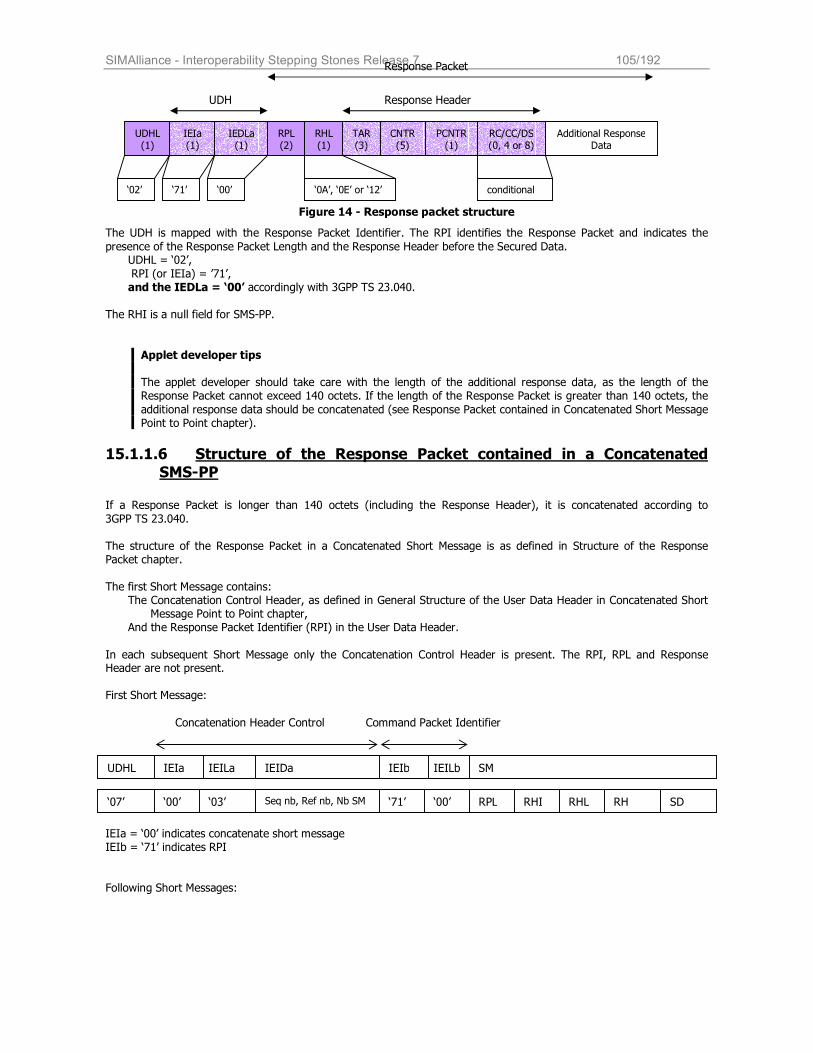
SIMAlliance - Interoperability Stepping Stones Release 7 105/192
Figure 14 - Response packet structure
The UDH is mapped with the Response Packet Identifier. The RPI identifies the Response Packet and indicates the
presence of the Response Packet Length and the Response Header before the Secured Data. UDHL = ‘02’,
RPI (or IEIa) = ’71’, and the IEDLa = ‘00’ accordingly with 3GPP TS 23.040.
The RHI is a null field for SMS-PP.
Applet developer tips The applet developer should take care with the length of the additional response data, as the length of the Response Packet cannot exceed 140 octets. If the length of the Response Packet is greater than 140 octets, the
additional response data should be concatenated (see Response Packet contained in Concatenated Short Message Point to Point chapter).
15.1.1.6 Structure of the Response Packet contained in a Concatenated
SMS-PP If a Response Packet is longer than 140 octets (including the Response Header), it is concatenated according to
3GPP TS 23.040.
The structure of the Response Packet in a Concatenated Short Message is as defined in Structure of the Response Packet chapter. The first Short Message contains:
The Concatenation Control Header, as defined in General Structure of the User Data Header in Concatenated Short Message Point to Point chapter,
And the Response Packet Identifier (RPI) in the User Data Header.
In each subsequent Short Message only the Concatenation Control Header is present. The RPI, RPL and Response Header are not present.
First Short Message:
IEIa = ‘00’ indicates concatenate short message IEIb = ‘71’ indicates RPI Following Short Messages:
IEILb IEILa UDHL IEIa IEIDa IEIb SM
Concatenation Header Control Command Packet Identifier
‘07’ ‘00’ ‘03’ Seq nb, Ref nb, Nb SM ‘71’ ‘00’ RPL RHI RHL RH SD
UDHL (1)
IEIa (1)
IEDLa (1)
RPL (2)
RHL (1)
TAR (3)
CNTR (5)
PCNTR (1)
RC/CC/DS (0, 4 or 8)
Additional Response Data
UDH Response Header
‘02’ ‘71’ ‘00’ ‘0A’, ‘0E’ or ‘12’ conditional
Response Packet
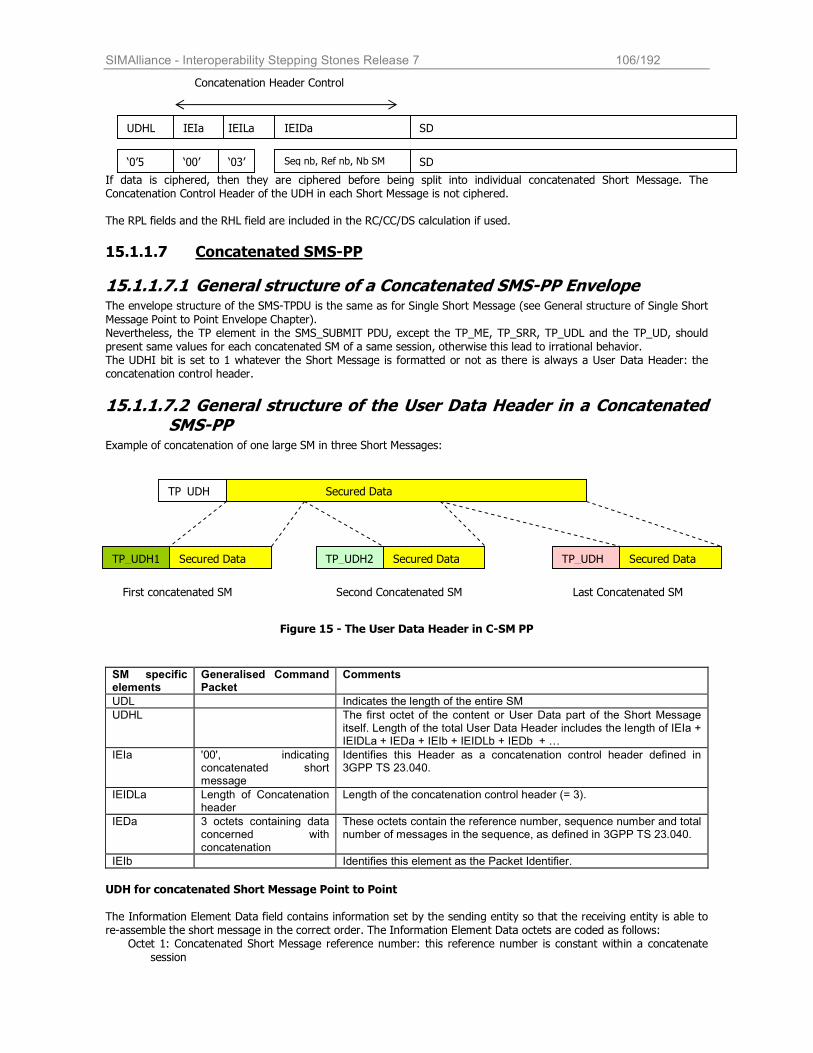
SIMAlliance - Interoperability Stepping Stones Release 7 106/192
If data is ciphered, then they are ciphered before being split into individual concatenated Short Message. The Concatenation Control Header of the UDH in each Short Message is not ciphered. The RPL fields and the RHL field are included in the RC/CC/DS calculation if used.
15.1.1.7 Concatenated SMS-PP
15.1.1.7.1 General structure of a Concatenated SMS-PP Envelope The envelope structure of the SMS-TPDU is the same as for Single Short Message (see General structure of Single Short
Message Point to Point Envelope Chapter). Nevertheless, the TP element in the SMS_SUBMIT PDU, except the TP_ME, TP_SRR, TP_UDL and the TP_UD, should present same values for each concatenated SM of a same session, otherwise this lead to irrational behavior. The UDHI bit is set to 1 whatever the Short Message is formatted or not as there is always a User Data Header: the concatenation control header.
15.1.1.7.2 General structure of the User Data Header in a Concatenated SMS-PP
Example of concatenation of one large SM in three Short Messages:
Figure 15 - The User Data Header in C-SM PP
SM specific elements
Generalised Command Packet
Comments
UDL Indicates the length of the entire SM
UDHL The first octet of the content or User Data part of the Short Message itself. Length of the total User Data Header includes the length of IEIa + IEIDLa + IEDa + IEIb + IEIDLb + IEDb + …
IEIa '00', indicating concatenated short message
Identifies this Header as a concatenation control header defined in 3GPP TS 23.040.
IEIDLa Length of Concatenation header
Length of the concatenation control header (= 3).
IEDa 3 octets containing data concerned with concatenation
These octets contain the reference number, sequence number and total number of messages in the sequence, as defined in 3GPP TS 23.040.
IEIb Identifies this element as the Packet Identifier.
UDH for concatenated Short Message Point to Point The Information Element Data field contains information set by the sending entity so that the receiving entity is able to re-assemble the short message in the correct order. The Information Element Data octets are coded as follows:
Octet 1: Concatenated Short Message reference number: this reference number is constant within a concatenate session
TP_UDH1 Secured Data TP_UDH2 Secured Data TP_UDH Secured Data
TP_UDH Secured Data
First concatenated SM Second Concatenated SM Last Concatenated SM
IEILa UDHL IEIa IEIDa SD
Concatenation Header Control
‘0’5 ‘00’ ‘03’ Seq nb, Ref nb, Nb SM SD
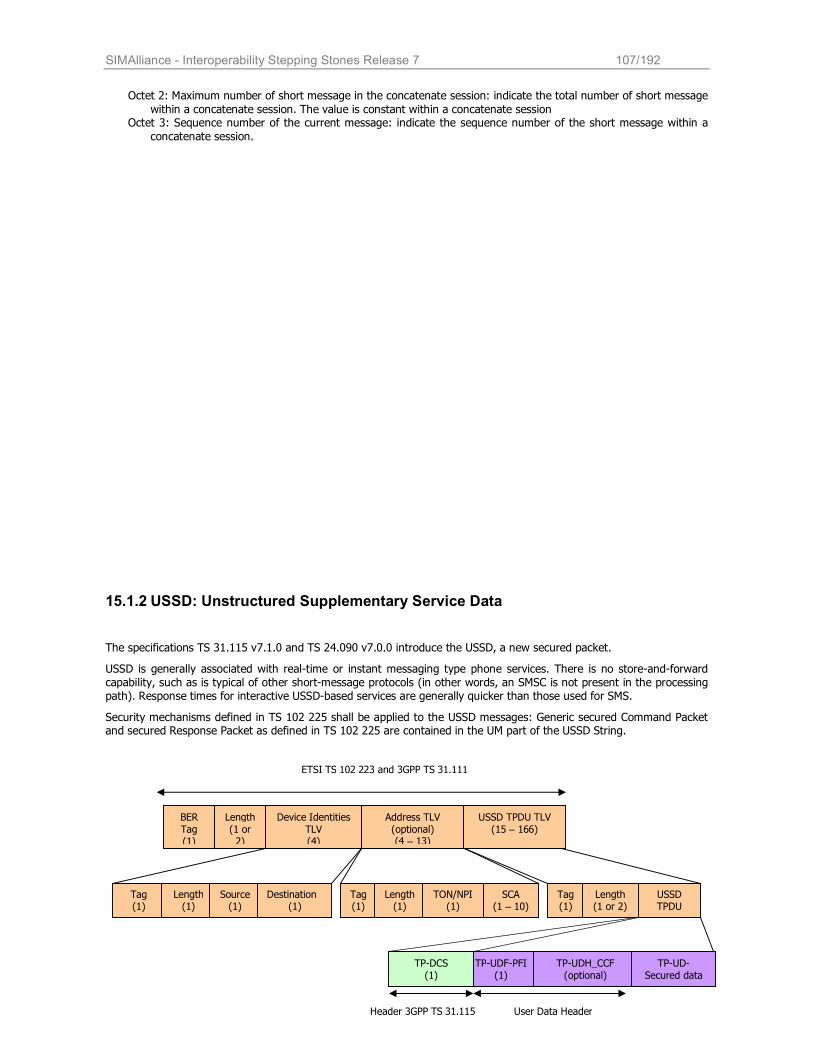
SIMAlliance - Interoperability Stepping Stones Release 7 107/192
Octet 2: Maximum number of short message in the concatenate session: indicate the total number of short message
within a concatenate session. The value is constant within a concatenate session Octet 3: Sequence number of the current message: indicate the sequence number of the short message within a
concatenate session.
15.1.2 USSD: Unstructured Supplementary Service Data
The specifications TS 31.115 v7.1.0 and TS 24.090 v7.0.0 introduce the USSD, a new secured packet.
USSD is generally associated with real-time or instant messaging type phone services. There is no store-and-forward capability, such as is typical of other short-message protocols (in other words, an SMSC is not present in the processing path). Response times for interactive USSD-based services are generally quicker than those used for SMS.
Security mechanisms defined in TS 102 225 shall be applied to the USSD messages: Generic secured Command Packet and secured Response Packet as defined in TS 102 225 are contained in the UM part of the USSD String.
Header 3GPP TS 31.115
BER Tag (1)
Length (1 or 2)
Device Identities TLV (4)
Address TLV (optional) (4 – 13)
USSD TPDU TLV (15 – 166)
Tag (1)
Length (1)
Source (1)
Destination (1)
Tag (1)
Length (1)
TON/NPI (1)
SCA (1 – 10)
Tag (1)
Length (1 or 2)
USSD TPDU
ETSI TS 102 223 and 3GPP TS 31.111
TP-UDF-PFI (1)
TP-UDH_CCF (optional)
TP-UD-Secured data
TP-DCS (1)
User Data Header
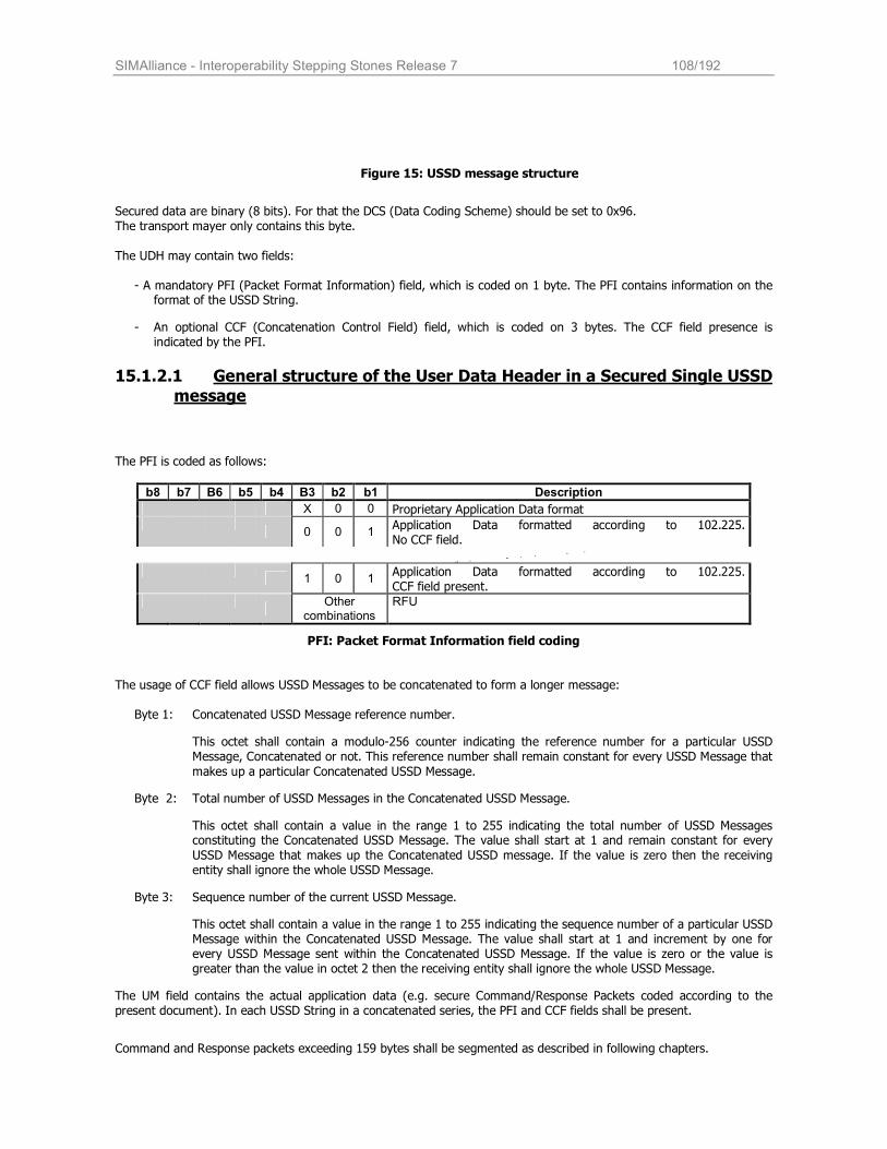
SIMAlliance - Interoperability Stepping Stones Release 7 108/192
Figure 15: USSD message structure
Secured data are binary (8 bits). For that the DCS (Data Coding Scheme) should be set to 0x96. The transport mayer only contains this byte.
The UDH may contain two fields:
- A mandatory PFI (Packet Format Information) field, which is coded on 1 byte. The PFI contains information on the format of the USSD String.
- An optional CCF (Concatenation Control Field) field, which is coded on 3 bytes. The CCF field presence is indicated by the PFI.
15.1.2.1 General structure of the User Data Header in a Secured Single USSD
message The PFI is coded as follows:
b8 b7 B6 b5 b4 B3 b2 b1 Description
X 0 0 Proprietary Application Data format
0 0 1 Application Data formatted according to 102.225. No CCF field.
1 0 1
Application Data formatted according to 102.225. CCF field present.
Other combinations
RFU
PFI: Packet Format Information field coding
The usage of CCF field allows USSD Messages to be concatenated to form a longer message:
Byte 1: Concatenated USSD Message reference number.
This octet shall contain a modulo-256 counter indicating the reference number for a particular USSD Message, Concatenated or not. This reference number shall remain constant for every USSD Message that
makes up a particular Concatenated USSD Message.
Byte 2: Total number of USSD Messages in the Concatenated USSD Message.
This octet shall contain a value in the range 1 to 255 indicating the total number of USSD Messages constituting the Concatenated USSD Message. The value shall start at 1 and remain constant for every
USSD Message that makes up the Concatenated USSD message. If the value is zero then the receiving entity shall ignore the whole USSD Message.
Byte 3: Sequence number of the current USSD Message.
This octet shall contain a value in the range 1 to 255 indicating the sequence number of a particular USSD Message within the Concatenated USSD Message. The value shall start at 1 and increment by one for every USSD Message sent within the Concatenated USSD Message. If the value is zero or the value is greater than the value in octet 2 then the receiving entity shall ignore the whole USSD Message.
The UM field contains the actual application data (e.g. secure Command/Response Packets coded according to the present document). In each USSD String in a concatenated series, the PFI and CCF fields shall be present.
Command and Response packets exceeding 159 bytes shall be segmented as described in following chapters.
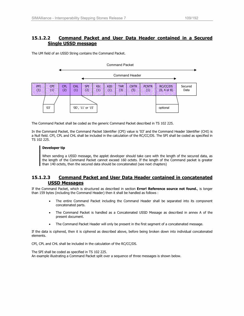
SIMAlliance - Interoperability Stepping Stones Release 7 109/192
15.1.2.2 Command Packet and User Data Header contained in a Secured
Single USSD message The UM field of an USSD String contains the Command Packet.
The Command Packet shall be coded as the generic Command Packet described in TS 102 225. In the Command Packet, the Command Packet Identifier (CPI) value is '03' and the Command Header Identifier (CHI) is
a Null field. CPI, CPL and CHL shall be included in the calculation of the RC/CC/DS. The SPI shall be coded as specified in TS 102 225.
Developer tip
When sending a USSD message, the applet developer should take care with the length of the secured data, as the length of the Command Packet cannot exceed 160 octets. If the length of the Command packet is greater than 140 octets, then the secured data should be concatenated (see next chapters)
15.1.2.3 Command Packet and User Data Header contained in concatenated
USSD Messages
If the Command Packet, which is structured as described in section Error! Reference source not found., is longer than 159 bytes (including the Command Header) then it shall be handled as follows :
• The entire Command Packet including the Command Header shall be separated into its component
concatenated parts.
• The Command Packet is handled as a Concatenated USSD Message as described in annex A of the
present document.
• The Command Packet Header will only be present in the first segment of a concatenated message.
If the data is ciphered, then it is ciphered as described above, before being broken down into individual concatenated elements. CPI, CPL and CHL shall be included in the calculation of the RC/CC/DS.
The SPI shall be coded as specified in TS 102 225. An example illustrating a Command Packet split over a sequence of three messages is shown below.
PFI (1)
CPL (2)
CHL (1)
SPI (2)
KIc (1)
KID (1)
TAR (3)
CNTR (5)
PCNTR (1)
RC/CC/DS (0, 4 or 8)
Secured
Data
Command Header
‘03’ ‘0D’, ‘11’ or ‘15’ optional
Command Packet
CPI (1)
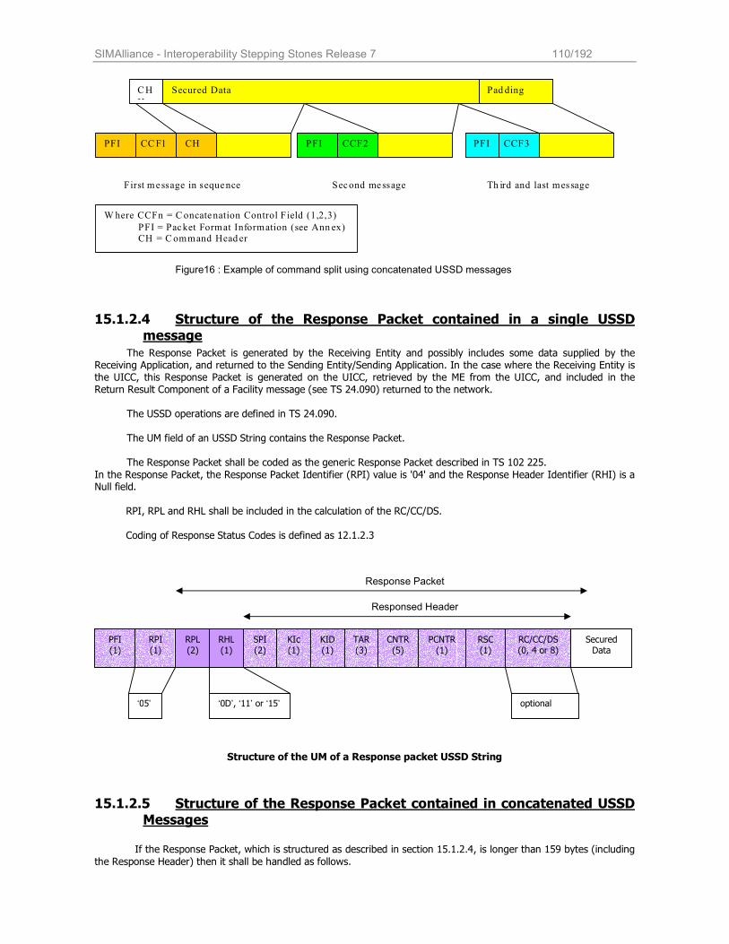
SIMAlliance - Interoperability Stepping Stones Release 7 110/192
CH
H
Secured Data Pad ding
PFI CCF1 CH PFI CCF2 PFI CCF3
First message in sequence Second message Th ird and last message
W here CCFn = Concatenation Control Field (1,2,3)
PFI = Packet Format Information (see Ann ex) CH = Command Head er
Figure16 : Example of command split using concatenated USSD messages
15.1.2.4 Structure of the Response Packet contained in a single USSD
message
The Response Packet is generated by the Receiving Entity and possibly includes some data supplied by the Receiving Application, and returned to the Sending Entity/Sending Application. In the case where the Receiving Entity is the UICC, this Response Packet is generated on the UICC, retrieved by the ME from the UICC, and included in the Return Result Component of a Facility message (see TS 24.090) returned to the network.
The USSD operations are defined in TS 24.090.
The UM field of an USSD String contains the Response Packet. The Response Packet shall be coded as the generic Response Packet described in TS 102 225.
In the Response Packet, the Response Packet Identifier (RPI) value is '04' and the Response Header Identifier (RHI) is a Null field.
RPI, RPL and RHL shall be included in the calculation of the RC/CC/DS.
Coding of Response Status Codes is defined as 12.1.2.3
Structure of the UM of a Response packet USSD String
15.1.2.5 Structure of the Response Packet contained in concatenated USSD
Messages
If the Response Packet, which is structured as described in section 15.1.2.4, is longer than 159 bytes (including
the Response Header) then it shall be handled as follows.
PFI (1)
RPL (2)
RHL (1)
SPI (2)
KIc (1)
KID (1)
TAR (3)
CNTR (5)
PCNTR (1)
RC/CC/DS (0, 4 or 8)
Secured Data
Responsed Header
‘05’ ‘0D’, ‘11’ or ‘15’ optional
Response Packet
RPI (1)
RSC (1)
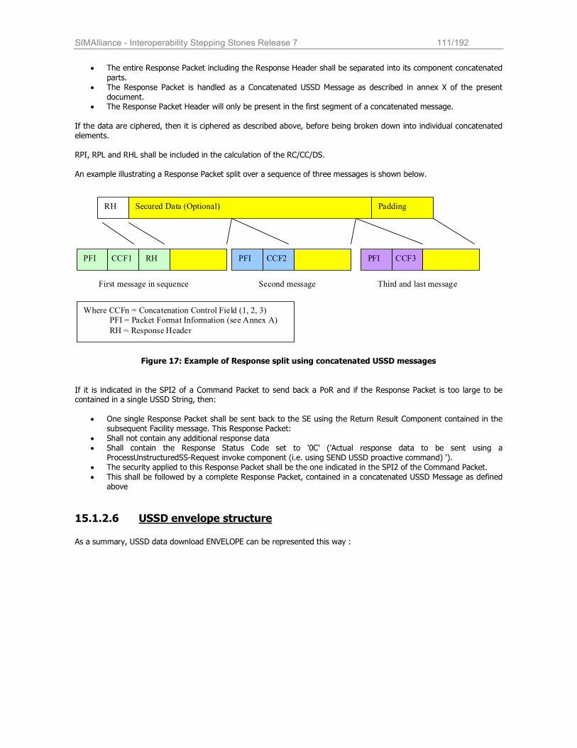
SIMAlliance - Interoperability Stepping Stones Release 7 111/192
• The entire Response Packet including the Response Header shall be separated into its component concatenated
parts. • The Response Packet is handled as a Concatenated USSD Message as described in annex X of the present
document. • The Response Packet Header will only be present in the first segment of a concatenated message.
If the data are ciphered, then it is ciphered as described above, before being broken down into individual concatenated elements.
RPI, RPL and RHL shall be included in the calculation of the RC/CC/DS.
An example illustrating a Response Packet split over a sequence of three messages is shown below.
RH Secured Data (Optional) Padding
PFI CCF1 RH PFI CCF2 PFI CCF3
First message in sequence Second message Third and last message
Where CCFn = Concatenation Control Field (1, 2, 3)
PFI = Packet Format Information (see Annex A)
RH = Response Header
Figure 17: Example of Response split using concatenated USSD messages
If it is indicated in the SPI2 of a Command Packet to send back a PoR and if the Response Packet is too large to be contained in a single USSD String, then:
• One single Response Packet shall be sent back to the SE using the Return Result Component contained in the
subsequent Facility message. This Response Packet:
• Shall not contain any additional response data • Shall contain the Response Status Code set to '0C' ('Actual response data to be sent using a
ProcessUnstructuredSS-Request invoke component (i.e. using SEND USSD proactive command) '). • The security applied to this Response Packet shall be the one indicated in the SPI2 of the Command Packet.
• This shall be followed by a complete Response Packet, contained in a concatenated USSD Message as defined above
15.1.2.6 USSD envelope structure
As a summary, USSD data download ENVELOPE can be represented this way :
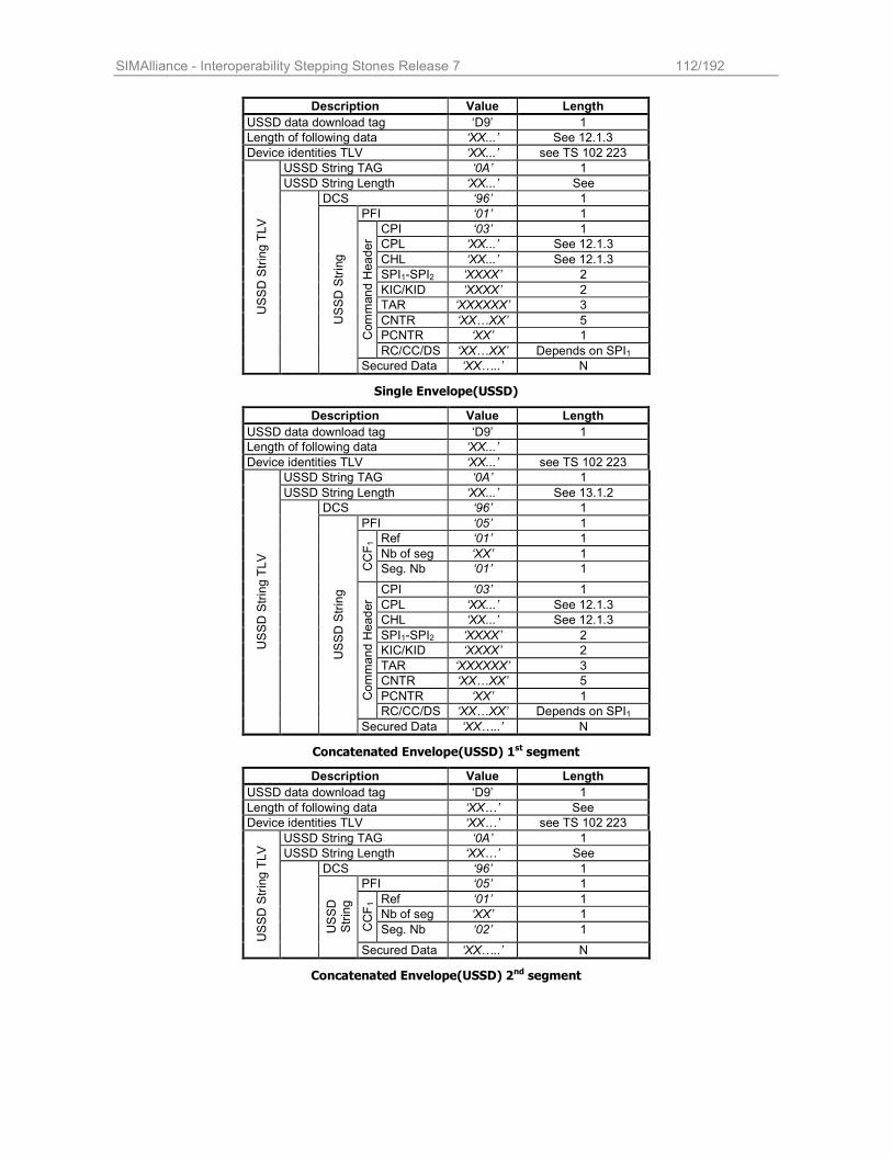
SIMAlliance - Interoperability Stepping Stones Release 7 112/192
Description Value Length
USSD data download tag ‘D9’ 1
Length of following data ‘XX...’ See 12.1.3
Device identities TLV ‘XX...’ see TS 102 223
USSD String TAG ‘0A’ 1
USSD String Length ‘XX...’ See
DCS ‘96’ 1
PFI ‘01’ 1
CPI ‘03’ 1
CPL ‘XX...’ See 12.1.3
CHL ‘XX...’ See 12.1.3
SPI1-SPI2 ‘XXXX’ 2
KIC/KID ‘XXXX’ 2
TAR ‘XXXXXX’ 3
CNTR ‘XX…XX’ 5
PCNTR ‘XX’ 1 Command Header
RC/CC/DS ‘XX…XX’ Depends on SPI1
USSD String TLV
USSD String
Secured Data ‘XX…..’ N
Single Envelope(USSD)
Description Value Length
USSD data download tag ‘D9’ 1
Length of following data ‘XX...’
Device identities TLV ‘XX...’ see TS 102 223
USSD String TAG ‘0A’ 1
USSD String Length ‘XX...’ See 13.1.2
DCS ‘96’ 1
PFI ‘05’ 1
Ref ‘01’ 1
Nb of seg ‘XX’ 1
CCF1
Seg. Nb ‘01’ 1
CPI ‘03’ 1
CPL ‘XX...’ See 12.1.3
CHL ‘XX...’ See 12.1.3
SPI1-SPI2 ‘XXXX’ 2
KIC/KID ‘XXXX’ 2
TAR ‘XXXXXX’ 3
CNTR ‘XX…XX’ 5
PCNTR ‘XX’ 1 Command Header
RC/CC/DS ‘XX…XX’ Depends on SPI1
USSD String TLV
USSD String
Secured Data ‘XX…..’ N
Concatenated Envelope(USSD) 1st segment
Description Value Length
USSD data download tag ‘D9’ 1
Length of following data ‘XX…’ See
Device identities TLV ‘XX…’ see TS 102 223
USSD String TAG ‘0A’ 1
USSD String Length ‘XX…’ See
DCS ‘96’ 1
PFI ‘05’ 1
Ref ‘01’ 1
Nb of seg ‘XX’ 1
CCF1
Seg. Nb ‘02’ 1
USSD String TLV
USSD
String
Secured Data ‘XX…..’ N
Concatenated Envelope(USSD) 2nd segment
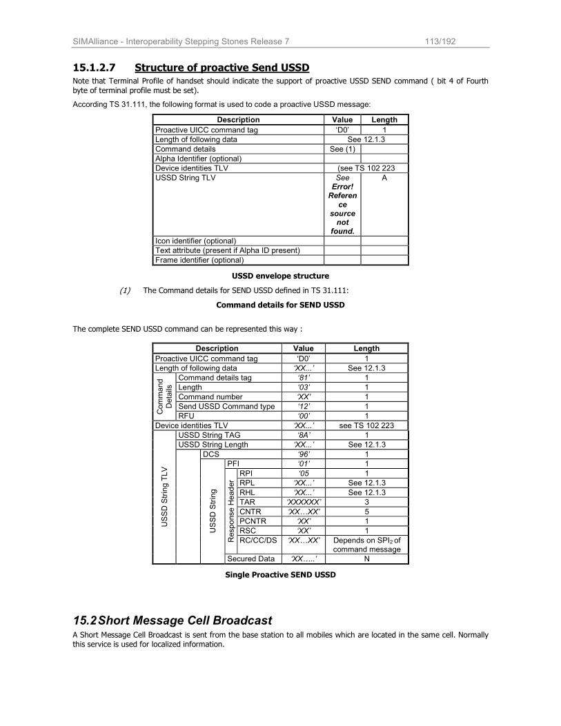
SIMAlliance - Interoperability Stepping Stones Release 7 113/192
15.1.2.7 Structure of proactive Send USSD Note that Terminal Profile of handset should indicate the support of proactive USSD SEND command ( bit 4 of Fourth
byte of terminal profile must be set).
According TS 31.111, the following format is used to code a proactive USSD message:
Description Value Length
Proactive UICC command tag ‘D0’ 1
Length of following data See 12.1.3
Command details See (1)
Alpha Identifier (optional)
Device identities TLV (see TS 102 223
USSD String TLV See Error! Reference
source not
found.
A
Icon identifier (optional)
Text attribute (present if Alpha ID present)
Frame identifier (optional)
USSD envelope structure
(1) The Command details for SEND USSD defined in TS 31.111:
Command details for SEND USSD
The complete SEND USSD command can be represented this way :
Description Value Length
Proactive UICC command tag ‘D0’ 1
Length of following data ‘XX...’ See 12.1.3
Command details tag ‘81’ 1
Length ‘03’ 1
Command number ‘XX’ 1
Send USSD Command type ‘12’ 1
Command
Details
RFU ‘00’ 1
Device identities TLV ‘XX...’ see TS 102 223
USSD String TAG ‘8A’ 1
USSD String Length ‘XX...’ See 12.1.3
DCS ‘96’ 1
PFI ‘01’ 1
RPI ‘05 1
RPL ‘XX...’ See 12.1.3
RHL ‘XX...’ See 12.1.3
TAR ‘XXXXXX’ 3
CNTR ‘XX…XX’ 5
PCNTR ‘XX’ 1
RSC ‘XX’ 1
Response Header
RC/CC/DS ‘XX…XX’ Depends on SPI2 of command message
USSD String TLV
USSD String
Secured Data ‘XX…..’ N
Single Proactive SEND USSD
15.2 Short Message Cell Broadcast A Short Message Cell Broadcast is sent from the base station to all mobiles which are located in the same cell. Normally this service is used for localized information.
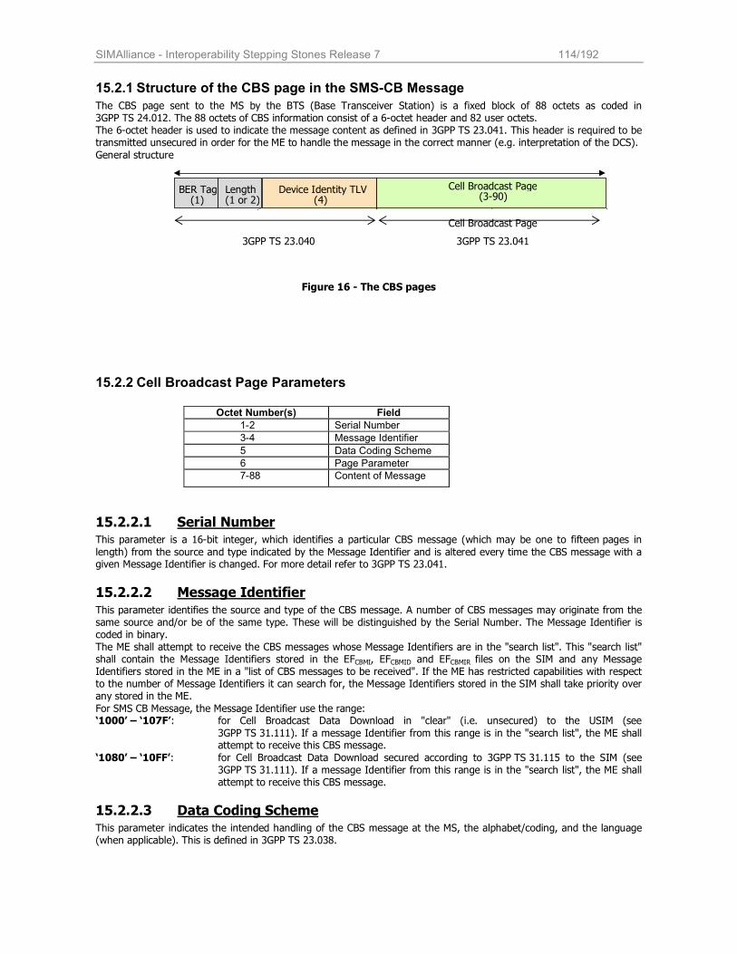
SIMAlliance - Interoperability Stepping Stones Release 7 114/192
15.2.1 Structure of the CBS page in the SMS-CB Message
The CBS page sent to the MS by the BTS (Base Transceiver Station) is a fixed block of 88 octets as coded in 3GPP TS 24.012. The 88 octets of CBS information consist of a 6-octet header and 82 user octets. The 6-octet header is used to indicate the message content as defined in 3GPP TS 23.041. This header is required to be transmitted unsecured in order for the ME to handle the message in the correct manner (e.g. interpretation of the DCS).
General structure
Figure 16 - The CBS pages
15.2.2 Cell Broadcast Page Parameters
Octet Number(s) Field
1-2 Serial Number
3-4 Message Identifier
5 Data Coding Scheme
6 Page Parameter
7-88 Content of Message
15.2.2.1 Serial Number This parameter is a 16-bit integer, which identifies a particular CBS message (which may be one to fifteen pages in
length) from the source and type indicated by the Message Identifier and is altered every time the CBS message with a given Message Identifier is changed. For more detail refer to 3GPP TS 23.041.
15.2.2.2 Message Identifier
This parameter identifies the source and type of the CBS message. A number of CBS messages may originate from the same source and/or be of the same type. These will be distinguished by the Serial Number. The Message Identifier is coded in binary. The ME shall attempt to receive the CBS messages whose Message Identifiers are in the "search list". This "search list" shall contain the Message Identifiers stored in the EFCBMI, EFCBMID and EFCBMIR files on the SIM and any Message Identifiers stored in the ME in a "list of CBS messages to be received". If the ME has restricted capabilities with respect to the number of Message Identifiers it can search for, the Message Identifiers stored in the SIM shall take priority over any stored in the ME.
For SMS CB Message, the Message Identifier use the range: ‘1000’ – ‘107F’: for Cell Broadcast Data Download in "clear" (i.e. unsecured) to the USIM (see
3GPP TS 31.111). If a message Identifier from this range is in the "search list", the ME shall attempt to receive this CBS message.
‘1080’ – ‘10FF’: for Cell Broadcast Data Download secured according to 3GPP TS 31.115 to the SIM (see 3GPP TS 31.111). If a message Identifier from this range is in the "search list", the ME shall attempt to receive this CBS message.
15.2.2.3 Data Coding Scheme This parameter indicates the intended handling of the CBS message at the MS, the alphabet/coding, and the language (when applicable). This is defined in 3GPP TS 23.038.
BER Tag (1)
Length (1 or 2)
Device Identity TLV (4)
Cell Broadcast Page
Cell Broadcast Page
(3-90)
3GPP TS 23.040 3GPP TS 23.041
SIMAlliance - Interoperability Stepping Stones Release 7 115/192
15.2.2.4 Page Parameter This parameter is coded as two 4-bit fields. The first field (bits 0-3) indicates the binary value of the total number of
pages in the CBS message and the second field (bits 4-7) indicates binary the page number within that sequence. The coding starts at “0001”, with “0000” reserved. If a mobile receives the code “0000” in either the first field or the second field then it shall treat the CBS message exactly the same as a CBS message with page parameter “0001 0001” (i.e. a single page message).
15.2.2.5 Content of Message This parameter is a copy of the 'CBS-Message-Information-Page' as sent from the CBC (Cell Broadcast Centre) to the
BSC (Base Station Controller).
The content of the message is secured as defined in this document.
15.2.3 A Command Packet contained in a SMS-CB message
The relationship between the Command Packet and its inclusion in the SMS-CB message structure is indicated in the table above.
Command Packet in CBS page of an SMS-CB message: SMS-CB specific elements
Generalised Command Packet Elements
Comments
SN Refer to 3GPP TS 23.041. Coded on 2 octets containing the ID of a particular message.
MID CPI='1080' to '109F' Coded on 2 octets containing the source and type of the message. The Command Packet Identifier range is reserved in 3GPP TS 23.041. (see note)
DCS Refer to 3GPP TS 23.041. Coded on 1 octet containing the alphabet coding and language as defined in 3GPP TS 23.038.
PP Refer to 3GPP TS 23.041. Coded on 1 octet to indicate the page number and total number of pages.
Content of Message
CPL Length of the Command Packet, coded over 2 octets, and shall not be coded according to ISO/IEC 7816-6.
CHI The Command Header Identifier. Null field.
CHL This shall indicate the number of octets from and including the SPI to the end of the RC/CC/DS field. Binary coded over 1 octet.
SPI to RC/CC/DS in the Command Header
The remainder of the Command Header.
Secured Data Application Message, including possible padding octets.
NOTE: Generally, the CPI is coded on 1 octet, as specified in Structure of Command Packet Chapter. However,
the CPI for the SMS-CB message is coded on 2 octets as the values reserved in 3GPP TS 23.041 to identify the Command Packet are MID values which are coded on 2 octets.
15.2.4 Multiple Short Message Cell Broadcast Description
It is possible to send more than 82 octets with Short Message CBC. The Command Packet is then split over a sequence of SMS_CB pages.
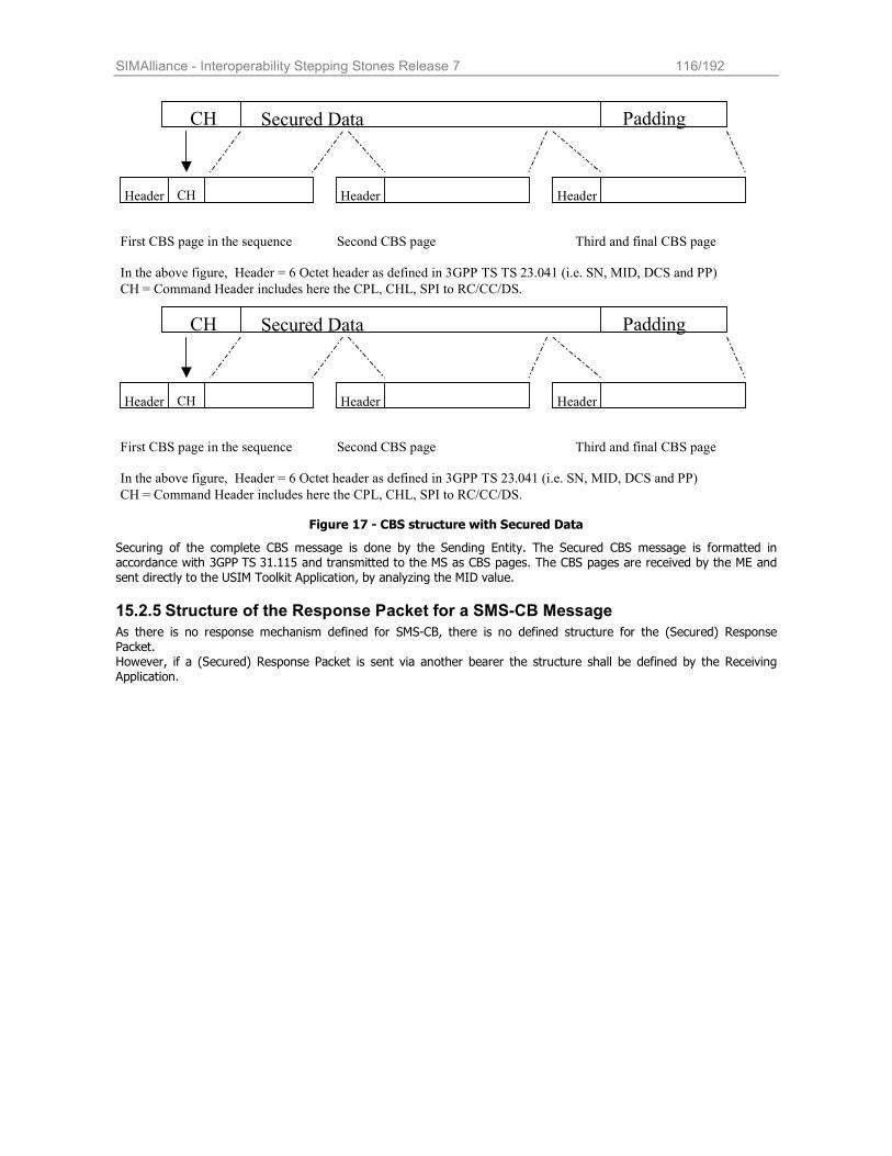
SIMAlliance - Interoperability Stepping Stones Release 7 116/192
Header Header HeaderCH
CH Secured Data Padding
First CBS page in the sequence Second CBS page Third and final CBS page
In the above figure, Header = 6 Octet header as defined in 3GPP TS TS 23.041 (i.e. SN, MID, DCS and PP)
andCH = Command Header includes here the CPL, CHL, SPI to RC/CC/DS.
Header Header HeaderCH
CH Secured Data Padding
First CBS page in the sequence Second CBS page Third and final CBS page
In the above figure, Header = 6 Octet header as defined in 3GPP TS 23.041 (i.e. SN, MID, DCS and PP)
andCH = Command Header includes here the CPL, CHL, SPI to RC/CC/DS.
Figure 17 - CBS structure with Secured Data
Securing of the complete CBS message is done by the Sending Entity. The Secured CBS message is formatted in accordance with 3GPP TS 31.115 and transmitted to the MS as CBS pages. The CBS pages are received by the ME and sent directly to the USIM Toolkit Application, by analyzing the MID value.
15.2.5 Structure of the Response Packet for a SMS-CB Message
As there is no response mechanism defined for SMS-CB, there is no defined structure for the (Secured) Response Packet. However, if a (Secured) Response Packet is sent via another bearer the structure shall be defined by the Receiving Application.
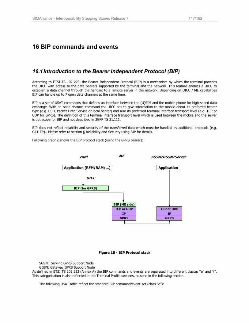
SIMAlliance - Interoperability Stepping Stones Release 7 117/192
16 BIP commands and events
16.1 Introduction to the Bearer Independent Protocol (BIP) According to ETSI TS 102 223, the Bearer Independent Protocol (BIP) is a mechanism by which the terminal provides the UICC with access to the data bearers supported by the terminal and the network. This feature enables a UICC to
establish a data channel through the handset to a remote server in the network. Depending on UICC / ME capabilities BIP can handle up to 7 open data channels at the same time. BIP is a set of USAT commands that defines an interface between the (U)SIM and the mobile phone for high-speed data exchange. With an open channel command the UICC has to give information to the mobile about its preferred bearer type (e.g. CSD, Packet Data Service or local bearer) and also its preferred terminal interface transport level (e.g. TCP or UDP for GPRS). The definition of this terminal interface transport level which is used between the mobile and the server
is out scope for BIP and not described in 3GPP TS 31.111.
BIP does not reflect reliability and security of the transferred data which must be handled by additional protocols (e.g. CAT-TP).. Please refer to section § Reliability and Security using BIP for details.
Following graphic shows the BIP protocol stack (using the GPRS bearer):
Figure 18 - BIP Protocol stack
SGSN: Serving GPRS Support Node
GGSN: Gateway GPRS Support Node As defined in ETSI TS 102 223 (Annex A) the BIP commands and events are separated into different classes “e” and “f”.
This categorization is also reflected in the Terminal Profile sections, as seen in the following section.
The following USAT table reflect the standard BIP command/event-set (class “e”):
Application (RFM/RAM/...)
BIP (for GPRS)
BIP (ME side)
TCP or UDP
IP
GPRS
TCP or UDP
IP
GPRS
Application
UICC
ME SGSN/GGSN/Server card
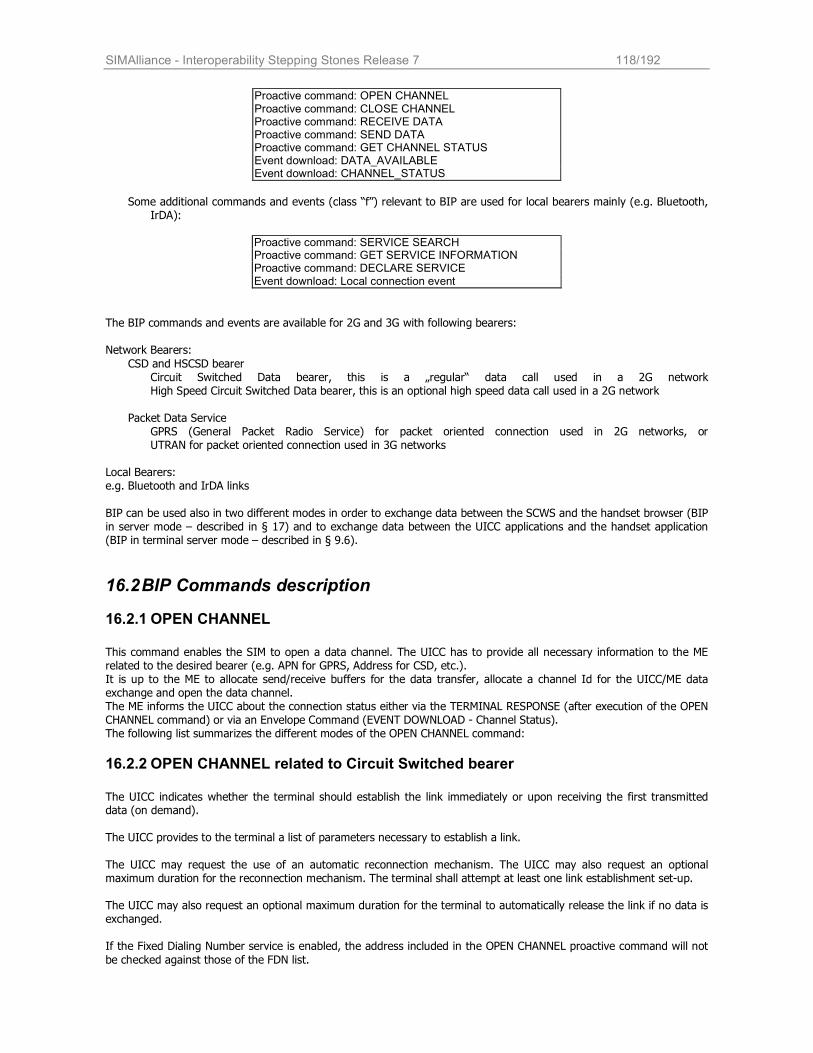
SIMAlliance - Interoperability Stepping Stones Release 7 118/192
Proactive command: OPEN CHANNEL Proactive command: CLOSE CHANNEL Proactive command: RECEIVE DATA Proactive command: SEND DATA Proactive command: GET CHANNEL STATUS Event download: DATA_AVAILABLE Event download: CHANNEL_STATUS
Some additional commands and events (class “f”) relevant to BIP are used for local bearers mainly (e.g. Bluetooth,
IrDA):
Proactive command: SERVICE SEARCH Proactive command: GET SERVICE INFORMATION Proactive command: DECLARE SERVICE Event download: Local connection event
The BIP commands and events are available for 2G and 3G with following bearers:
Network Bearers:
CSD and HSCSD bearer Circuit Switched Data bearer, this is a „regular“ data call used in a 2G network High Speed Circuit Switched Data bearer, this is an optional high speed data call used in a 2G network
Packet Data Service
GPRS (General Packet Radio Service) for packet oriented connection used in 2G networks, or UTRAN for packet oriented connection used in 3G networks
Local Bearers: e.g. Bluetooth and IrDA links
BIP can be used also in two different modes in order to exchange data between the SCWS and the handset browser (BIP in server mode – described in § 17) and to exchange data between the UICC applications and the handset application (BIP in terminal server mode – described in § 9.6).
16.2 BIP Commands description
16.2.1 OPEN CHANNEL
This command enables the SIM to open a data channel. The UICC has to provide all necessary information to the ME related to the desired bearer (e.g. APN for GPRS, Address for CSD, etc.). It is up to the ME to allocate send/receive buffers for the data transfer, allocate a channel Id for the UICC/ME data exchange and open the data channel. The ME informs the UICC about the connection status either via the TERMINAL RESPONSE (after execution of the OPEN CHANNEL command) or via an Envelope Command (EVENT DOWNLOAD - Channel Status). The following list summarizes the different modes of the OPEN CHANNEL command:
16.2.2 OPEN CHANNEL related to Circuit Switched bearer
The UICC indicates whether the terminal should establish the link immediately or upon receiving the first transmitted data (on demand).
The UICC provides to the terminal a list of parameters necessary to establish a link.
The UICC may request the use of an automatic reconnection mechanism. The UICC may also request an optional maximum duration for the reconnection mechanism. The terminal shall attempt at least one link establishment set-up. The UICC may also request an optional maximum duration for the terminal to automatically release the link if no data is exchanged. If the Fixed Dialing Number service is enabled, the address included in the OPEN CHANNEL proactive command will not
be checked against those of the FDN list.
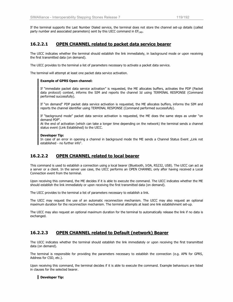
SIMAlliance - Interoperability Stepping Stones Release 7 119/192
If the terminal supports the Last Number Dialed service, the terminal does not store the channel set-up details (called
party number and associated parameters) sent by this UICC command in EFLND.
16.2.2.1 OPEN CHANNEL related to packet data service bearer
The UICC indicates whether the terminal should establish the link immediately, in background mode or upon receiving the first transmitted data (on demand). The UICC provides to the terminal a list of parameters necessary to activate a packet data service. The terminal will attempt at least one packet data service activation.
Example of GPRS Open channel:
If “immediate packet data service activation” is requested, the ME allocates buffers, activates the PDP (Packet data protocol) context, informs the SIM and reports the channel Id using TERMINAL RESPONSE (Command performed successfully). If “on demand“ PDP packet data service activation is requested, the ME allocates buffers, informs the SIM and
reports the channel identifier using TERMINAL RESPONSE (Command performed successfully).
If “background mode” packet data service activation is requested, the ME does the same steps as under “on demand PDP“.
At the end of activation (which can take a longer time depending on the network) the terminal sends a channel status event (Link Established) to the UICC.
Developer Tip: In case of an error in opening a channel in background mode the ME sends a Channel Status Event „Link not established - no further info“.
16.2.2.2 OPEN CHANNEL related to local bearer
This command is used to establish a connection using a local bearer (Bluetooth, IrDA, RS232, USB). The UICC can act as a server or a client. In the server use case, the UICC performs an OPEN CHANNEL only after having received a Local
Connection event from the terminal.
Upon receiving this command, the ME decides if it is able to execute the command. The UICC indicates whether the ME should establish the link immediately or upon receiving the first transmitted data (on demand). The UICC provides to the terminal a list of parameters necessary to establish a link. The UICC may request the use of an automatic reconnection mechanism. The UICC may also request an optional maximum duration for the reconnection mechanism. The terminal attempts at least one link establishment set-up. The UICC may also request an optional maximum duration for the terminal to automatically release the link if no data is exchanged.
16.2.2.3 OPEN CHANNEL related to Default (network) Bearer
The UICC indicates whether the terminal should establish the link immediately or upon receiving the first transmitted data (on demand). The terminal is responsible for providing the parameters necessary to establish the connection (e.g. APN for GPRS, Address for CSD, etc.). Upon receiving this command, the terminal decides if it is able to execute the command. Example behaviours are listed
in clauses for the selected bearer.
Developer Tip:
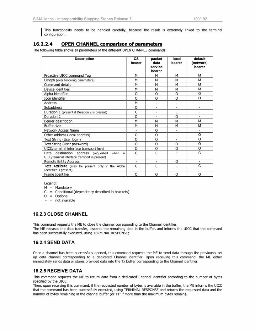
SIMAlliance - Interoperability Stepping Stones Release 7 120/192
This functionality needs to be handled carefully, because the result is extremely linked to the terminal
configuration.
16.2.2.4 OPEN CHANNEL comparison of parameters
The following table shows all parameters of the different OPEN CHANNEL commands:
Description CS bearer
packet data
service bearer
local bearer
default (network) bearer
Proactive UICC command Tag M M M M
Length (over following parameters) M M M M
Command details M M M M
Device identities M M M M
Alpha identifier O O O O
Icon identifier O O O O
Address M - - -
Subaddress O - - -
Duration 1 (present if Duration 2 is present) C - C -
Duration 2 O - O -
Bearer description M M M M
Buffer size M M M M
Network Access Name - O - -
Other address (local address) O O - O
Text String (User login) O O - O
Text String (User password) O O O O
UICC/terminal interface transport level O O O O
Data destination address (requested when a
UICC/terminal interface transport is present) C C C C
Remote Entity Address - - O -
Text Attribute (may be present only if the Alpha Identifier is present)
C C C C
Frame Identifier O O O O
Legend:
M = Mandatory C = Conditional (dependency described in brackets) O = Optional - = not available
16.2.3 CLOSE CHANNEL
This command requests the ME to close the channel corresponding to the Channel identifier. The ME releases the data transfer, discards the remaining data in the buffer, and informs the UICC that the command has been successfully executed, using TERMINAL RESPONSE;
16.2.4 SEND DATA
Once a channel has been successfully opened, this command requests the ME to send data through the previously set up data channel corresponding to a dedicated Channel identifier. Upon receiving this command, the ME either immediately sends data or stores provided data into the Tx buffer corresponding to the Channel identifier.
16.2.5 RECEIVE DATA
This command requests the ME to return data from a dedicated Channel identifier according to the number of bytes specified by the UICC. Then, upon receiving this command, if the requested number of bytes is available in the buffer, the ME informs the UICC that the command has been successfully executed, using TERMINAL RESPONSE and returns the requested data and the number of bytes remaining in the channel buffer (or 'FF' if more than the maximum bytes remain).
SIMAlliance - Interoperability Stepping Stones Release 7 121/192
16.2.6 GET CHANNEL STATUS
This command requests the ME to return a Channel status for each dedicated Channel identifier using TERMINAL RESPONSE. Channel Status information contains e.g. Channel Identifier, Link establishment status, Link dropping.
16.2.7 SERVICE SEARCH
This command is used to search for the availability of a local service in the environment of the terminal, such as
Bluetooth or IrDA. The UICC may provide a Device Filter. The devices responding to the service search are then part of the set given by
Device Filter. If the Device Filter parameter is not present, no filter on the type of equipment is done by the terminal. The UICC provides a Service Search parameter. The devices responding to the service search then support the
requested service.
16.2.8 GET SERVICE INFORMATION
This proactive command is used to look for the complete service record related to a service. By service record, it is
meant all information that allows the UICC to define precisely the service (e.g. protocol stacks). The UICC provides the Attribute Information parameter which indicates which detailed information is required.
If the terminal is able to execute the command the terminal performs the search for the service details and informs the
UICC using TERMINAL RESPONSE (command performed successfully, Service Record). The Service Record is then used as argument of an Open Channel proactive command. If the CAT application already has all information concerning the service, it may directly try to connect the service performing an OPEN CHANNEL, and bypass the GET SERVICE INFORMATION step.
16.2.9 DECLARE SERVICE
This command allows the UICC to download into the terminal service database the services that the card provides as a
server. The declaration is to be made on a service by service basis, at the set-up (e.g. after the profile download). The UICC indicates whether the terminal is required to add a new service in the terminal service database or to remove a
service from the terminal service database. When adding a new service, the UICC provides a Service Record that the terminal is required to register into its local
service database. When removing a service, the UICC provides the Service Identifier which uniquely identifies the service to be deleted from the database.
If the terminal is able to execute the command the terminal informs the UICC that the command has been successfully performed using TERMINAL RESPONSE. Note that a service can be coded using a coding type issued from a specific local bearer technology (e.g. Bluetooth or IrDA); however this service is considered by the terminal as available for any bearer.
16.3 BIP Events description
16.3.1 EVENT DOWNLOAD (DATA AVAILABLE):
If the applet is registered to this event (through the ToolkitRegistry.setEvent() method), and once the targeted channel buffer is empty when new data arrives in it, the ME informs the UICC that this has occurred, by using the ENVELOPE (EVENT DOWNLOAD – Data available).
16.3.2 EVENT DOWNLOAD (CHANNEL STATUS)
The Channel Status event is sent from the ME to the UICC if
the link was established or establishing failed (after an OPEN CHANNEL in background mode); or a link enters an error condition; or any other error.
SIMAlliance - Interoperability Stepping Stones Release 7 122/192
The event is only sent, if the error condition is not resulting from the execution of a proactive command and if the
Channel Status event is part of the current SET UP EVENT LIST.
From Rel. 6 on the structure of the Envelope (Event Download - Channel Status) contains a Bearer description data object, which is only present after an OPEN CHANNEL in background mode. See example in Annex I in ETSI TS 102 223
16.3.3 EVENT DOWNLOAD LOCAL CONNECTION
This event notifies the card that a local event has been set up, indicates the Remote Entity Address and Interface Transport Level (UDP, TCP).
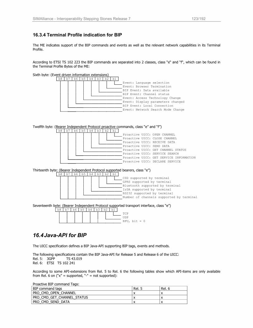
SIMAlliance - Interoperability Stepping Stones Release 7 123/192
16.3.4 Terminal Profile indication for BIP
The ME indicates support of the BIP commands and events as well as the relevant network capabilities in its Terminal Profile.
According to ETSI TS 102 223 the BIP commands are separated into 2 classes, class “e“ and “f“, which can be found in the Terminal Profile Bytes of the ME: Sixth byte: (Event driven information extensions)
b8 b7 b6 b5 b4 b3 b2 b1
Event: Language selection
Event: Browser Termination
BIP Event: Data available
BIP Event: Channel status
Event: Access Technology Change
Event: Display parameters changed
BIP Event: Local Connection
Event: Network Search Mode Change
Twelfth byte: (Bearer Independent Protocol proactive commands, class “e” and “f”)
b8 b7 b6 b5 b4 b3 b2 b1
Proactive UICC: OPEN CHANNEL
Proactive UICC: CLOSE CHANNEL
Proactive UICC: RECEIVE DATA
Proactive UICC: SEND DATA
Proactive UICC: GET CHANNEL STATUS
Proactive UICC: SERVICE SEARCH
Proactive UICC: GET SERVICE INFORMATION
Proactive UICC: DECLARE SERVICE
Thirteenth byte: (Bearer Independent Protocol supported bearers, class “e”) b8 b7 b6 b5 b4 b3 b2 b1
CSD supported by terminal
GPRS supported by terminal
Bluetooth supported by terminal
IrDA supported by terminal
RS232 supported by terminal
Number of channels supported by terminal
Seventeenth byte: (Bearer Independent Protocol supported transport interface, class “e”)
b8 b7 b6 b5 b4 b3 b2 b1
TCP
UDP
RFU, bit = 0
16.4 Java-API for BIP The UICC specification defines a BIP Java-API supporting BIP tags, events and methods.
The following specifications contain the BIP Java-API for Release 5 and Release 6 of the UICC: Rel. 5: 3GPP TS 43.019
Rel. 6: ETSI TS 102 241
According to some API-extensions from Rel. 5 to Rel. 6 the following tables show which API-items are only available from Rel. 6 on (“x” = supported, “-“ = not supported):
Proactive BIP command Tags:
BIP command tags Rel. 5 Rel. 6
PRO_CMD_OPEN_CHANNEL x x
PRO_CMD_GET_CHANNEL_STATUS x x
PRO_CMD_SEND_DATA x x
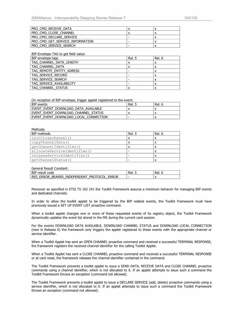
SIMAlliance - Interoperability Stepping Stones Release 7 124/192
PRO_CMD_RECEIVE_DATA x x
PRO_CMD_CLOSE_CHANNEL x x
PRO_CMD_DECLARE_SERVICE - x
PRO_CMD_GET_SERVICE_INFORMATION - x
PRO_CMD_SERVICE_SEARCH - x
BIP Envelope TAG to get field value:
BIP envelope tags Rel. 5 Rel. 6
TAG_CHANNEL_DATA_LENGTH x x
TAG_CHANNEL_DATA x x
TAG_REMOTE_ENTITY_ADRESS - x
TAG_SERVICE_RECORD - x
TAG_SERVICE_SEARCH - x
TAG_SERVICE_AVAILABILITY - x
TAG_CHANNEL_STATUS x x
On reception of BIP envelope, trigger applet registered to the event:
BIP events Rel. 5 Rel. 6
EVENT_EVENT_DOWNLOAD_DATA_AVAILABLE x x
EVENT_EVENT_DOWNLOAD_CHANNEL_STATUS x x
EVENT_EVENT_DOWNLOAD_LOCAL_CONNECTION - x
Methods:
BIP methods Rel. 5 Rel. 6
initClosechannel() x x
copyChannelData() x x
getChannelIdentifier() x x
allocateServiceIdentifier() - x
releaseServiceIdentifier() - x
getChannelStatus() - x
General Result Constant:
BIP result code Rel. 5 Rel. 6
RES_ERROR_BEARER_INDEPENDENT_PROTOCOL_ERROR - x
Moreover as specified in ETSI TS 102 241 the Toolkit Framework assures a minimum behavior for managing BIP events and dedicated channels:
In order to allow the toolkit applet to be triggered by the BIP related events, the Toolkit Framework must have
previously issued a SET UP EVENT LIST proactive command. When a toolkit applet changes one or more of these requested events of its registry object, the Toolkit Framework
dynamically updates the event list stored in the ME during the current card session.
For the events DOWNLOAD DATA AVAILABLE, DOWNLOAD CHANNEL STATUS and DOWNLOAD LOCAL CONNECTION (new in Release 6) the framework only triggers the applet registered to these events with the appropriate channel or
service identifier.
When a Toolkit Applet has sent an OPEN CHANNEL proactive command and received a successful TERMINAL RESPONSE, the framework registers the received channel identifier for the calling Toolkit Applet. When a Toolkit Applet has sent a CLOSE CHANNEL proactive command and received a successful TERMINAL RESPONSE or at card reset, the framework releases the channel identifier contained in the command. The Toolkit Framework prevents a toolkit applet to issue a SEND DATA, RECEIVE DATA and CLOSE CHANNEL proactive commands using a channel identifier, which is not allocated to it. If an applet attempts to issue such a command the Toolkit Framework throws an exception (command not allowed).
The Toolkit Framework prevents a toolkit applet to issue a DECLARE SERVICE (add, delete) proactive commands using a service identifier, which is not allocated to it. If an applet attempts to issue such a command the Toolkit Framework throws an exception (command not allowed).
SIMAlliance - Interoperability Stepping Stones Release 7 125/192
In case of the maximum number of allocated Services is exceeded the Toolkit Framework throws a Toolkit Exception (no service id available).
The Toolkit Framework prevents a toolkit applet to issue an OPEN CHANNEL proactive command if it exceeds the maximum number of channel allocated to this applet during the INSTALL [install]. If an applet attempts to issue such a command the Toolkit Framework throws an exception (command not allowed).
16.5 Reliability and Security using BIP As BIP is just a set of USAT commands to establish a channel from the ME to a remote server, there is no guarantee of reliable data exchange or end-to-end security, especially if a packet oriented bearer like GPRS is used together with UDP as transport interface where UDP-packets may get lost without notice. Reliability and security have to be achieved by additional protocols which are referenced here: Protocols to ensure reliability:
TCP: If this protocol is supported by the ME, it ensures that the data packages are fully transmitted and have the correct order.
CAT_TP: This protocol is defined in ETSI TS 102 127. It must be implemented on the UICC and is based on the UDP-support of mobiles. If the server also supports CAT_TP it ensures full packet delivery and correct packet order. CAT_TP also provides an identification of the UICC to the server. Protocol to ensure security: UICC secure packages: this protocol is defined in ETSI TS 102 225 and describes the use of secure protocol on a UICC
(originally derived from the GSM 03.48 standard). It also includes the use of CAT_TP for secure packet exchange.
16.6 Applet Developer tips
The registration to the event DOWNLOAD DATA AVAILABLE and event DOWNLOAD CHANNEL STATUS is effective once the toolkit applet has issued a successful OPEN CHANNEL proactive command, and valid till the first successful CLOSE CHANNEL or the end of the card session.
The registration to the event DOWNLOAD LOCAL CONNECTION is effective once the toolkit applet has issued a
successful DECLARE SERVICE (add) proactive command, and valid till the first successful DECLARE SERVICE (delete) or the end of the card session.
A successful TERMINAL RESPONSE means that the result of the proactive command execution belongs to command
performed category (i.e. General Result ='0x'). Without using an additional transport layer or security mechanism on top of BIP (e.g. CAT_TP), each applet
developer has to make sure that these issues are addressed by the applet. The ME will manage the data from
or to the UICC via TCP protocol, in order to ensure the data transmission to the remote entity.
BIP is fully integrated in the USAT specification 3GPP TS 31.111 and therefore has no influence on the existing USIM / USAT communication between UICC and Handset.
A BIP connection is always started by the UICC and it can not be started by the server. However the server can
request a BIP application for opening a channel using a remote command like PUSH as described in ETSI TS 102 226.
An example of a BIP APDU exchanges is available in the Annex I of the ETSI TS 102 223.
An example of an Applet using BIP API and BIP functionalities is available in Annex D of the 3GPP 43.019 (Rel. 5)
SIMAlliance - Interoperability Stepping Stones Release 7 126/192
17 SCWS
17.1 Scope The aim of this chapter is to give an overview of the Smart Card Web Server4 (SCWS) technology or UICC webserver5 technology. The SCWS is a standard HTTP 1.1 web server embedded in a card allowing the communication with a HTTP client on the handset e.g. a web browser. The SCWS v1.0 Enabler is specified by the Open Mobile Alliance (OMA). The ETSI SCP specification refer to the OMA specification and define also an API to forward HTTP requests to applets
(”SCWS Extensions”) and to send back the response of applets. This technology requires the link between the UICC and the ME to be either BIP or native TCP/IP.
17.2 Overview of SCWS Resources in xHTML format are stored in the card and can be browsed by the end user using the browser of the handset
through the widely deployed HTTP1.1 protocol. The OMA SCWS 1.0 Enabler specifications define:
- the URL to access the Smart Card Web Server - the transport protocol that is used to enable the communication between the HTTP applications in the device
(usually the browser) and the Smart Card Web Server - the HTTP profile implemented by the Smart Card Web Server - a secure remote administration protocol to administrate the Smart Card Web Server and the resources stored in
the card
17.3 Specifications SCWS is specified mainly by two standardization groups: OMA and ETSI.
The relevant specifications are
OMA specifications: Smartcard Web Serve rv1.0 Enabler Requirements Document (RD), Architecture Document (AD) and Technical Specification document (TS). The documents may be found on the OMA web site
http://www.openmobilealliance.org/Technical/release_program/SCWS_v1_0.aspx •
ETSI specifications:
• ETSI TS 102 588 Application invocation Application Programming Interface (API) by a UICC webserver for Java Card™ platform
• ETSI TS 102 223 Card Application Toolkit (CAT)
• ETSI TS 102 483 Internet Protocol connectivity between UICC and terminal
4 SCWS Smart Card Web Server is the Open Mobile Alliance (OMA) terminology 5 UICC web server is the ETSI SCP terminology
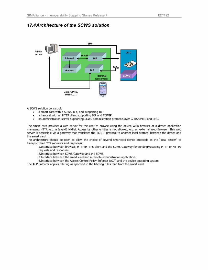
SIMAlliance - Interoperability Stepping Stones Release 7 127/192
17.4 Architecture of the SCWS solution
A SCWS solution consist of:
• a smart card with a SCWS in it, and supporting BIP • a handset with an HTTP client supporting BIP and TCP/IP
• an administration server supporting SCWS administration protocols over GPRS/UMTS and SMS.
The smart card provides a web server for the user to browse using the device WEB browser or a device application managing HTTP, e.g. a JavaME Midlet. Access by other entities is not allowed, e.g. an external Web-Browser. This web server is accessible via a gateway that translates the TCP/IP protocol to another local protocol between the device and the smart card. The architecture should be open to allow the choice of several smartcard-device protocols as the “local bearer” to transport the HTTP requests and responses.
1.Interface between browser, HTTP/HTTPS client and the SCWS Gateway for sending/receiving HTTP or HTTPS requests and responses.
2.Interface between SCWS Gateway and the SCWS. 3.Interface between the smart card and a remote administration application.
4.Interface between the Access Control Policy Enforcer (ACP) and the device operating system The ACP Enforcer applies filtering as specified in the filtering rules read from the smart card.
Data (GPRS, UMTS, …)
UICC
SCWS
Admin
server
Terminal
Equipment
Internet HTTP
BIP gateway
Access Control
TCP/IP
BIP network
SMS
BIP
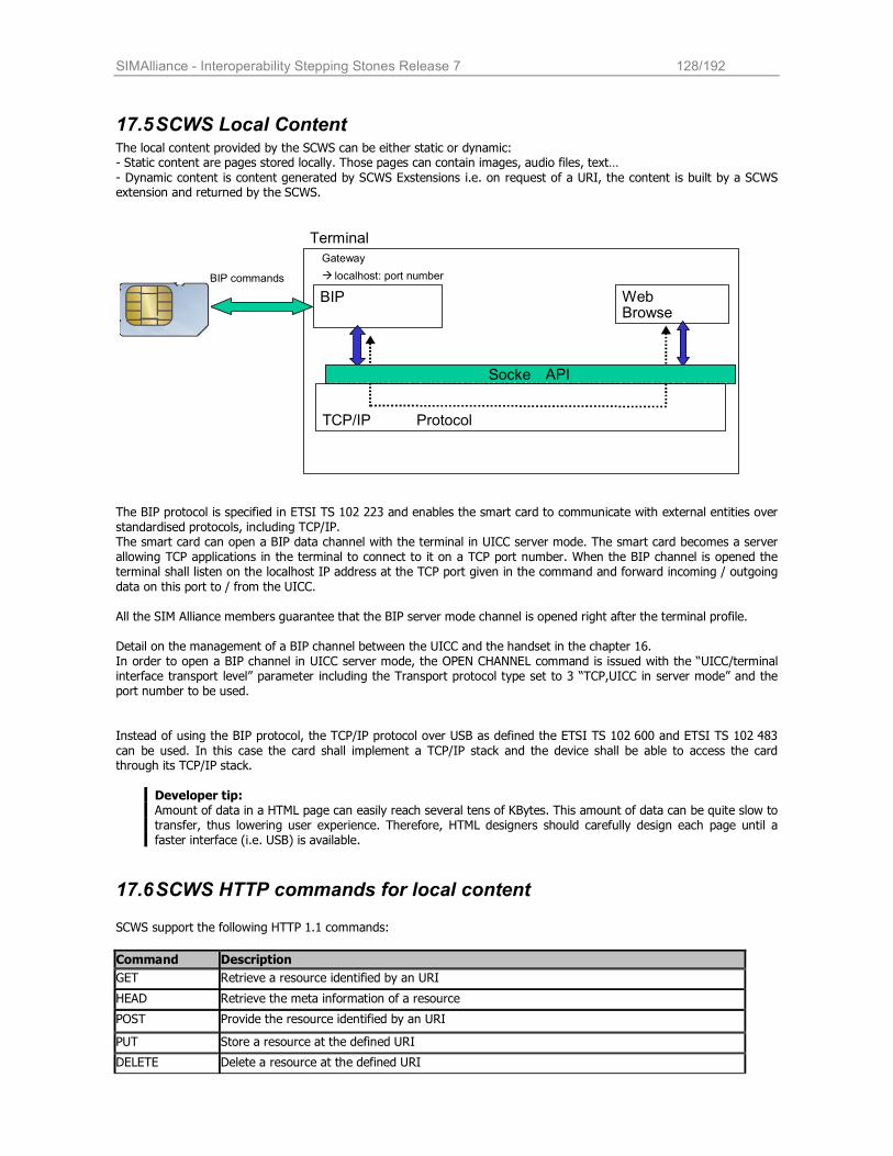
SIMAlliance - Interoperability Stepping Stones Release 7 128/192
17.5 SCWS Local Content The local content provided by the SCWS can be either static or dynamic: - Static content are pages stored locally. Those pages can contain images, audio files, text…
- Dynamic content is content generated by SCWS Exstensions i.e. on request of a URI, the content is built by a SCWS extension and returned by the SCWS.
The BIP protocol is specified in ETSI TS 102 223 and enables the smart card to communicate with external entities over standardised protocols, including TCP/IP. The smart card can open a BIP data channel with the terminal in UICC server mode. The smart card becomes a server allowing TCP applications in the terminal to connect to it on a TCP port number. When the BIP channel is opened the terminal shall listen on the localhost IP address at the TCP port given in the command and forward incoming / outgoing
data on this port to / from the UICC.
All the SIM Alliance members guarantee that the BIP server mode channel is opened right after the terminal profile.
Detail on the management of a BIP channel between the UICC and the handset in the chapter 16. In order to open a BIP channel in UICC server mode, the OPEN CHANNEL command is issued with the “UICC/terminal interface transport level” parameter including the Transport protocol type set to 3 “TCP,UICC in server mode” and the port number to be used.
Instead of using the BIP protocol, the TCP/IP protocol over USB as defined the ETSI TS 102 600 and ETSI TS 102 483
can be used. In this case the card shall implement a TCP/IP stack and the device shall be able to access the card through its TCP/IP stack.
Developer tip: Amount of data in a HTML page can easily reach several tens of KBytes. This amount of data can be quite slow to transfer, thus lowering user experience. Therefore, HTML designers should carefully design each page until a faster interface (i.e. USB) is available.
17.6 SCWS HTTP commands for local content SCWS support the following HTTP 1.1 commands:
Command Description
GET Retrieve a resource identified by an URI
HEAD Retrieve the meta information of a resource
POST Provide the resource identified by an URI
PUT Store a resource at the defined URI
DELETE Delete a resource at the defined URI
BIP
TCP/IP Protocol
Terminal
BIP commands Gateway � localhost: port number
Web Browse
Socket
API
SIMAlliance - Interoperability Stepping Stones Release 7 129/192
OPTIONS Request for information about the communication options (optional)
CONNECT Switch a proxy to tunneling mode (optional)
TRACE Application layer loopback of the request (optional)
17.7 Access Control and Security The SCWS provide the following security features:
- HTTP authentication - TLS over HTTP (HTTPs)
- Access Control Policy Enforcer
17.8 HTTP Authentication The SCWS provides authentication of the user using either the basic authentication mechanism or the digest authentication mechanism as defined by HTTP1.1 or more precisely in the RFC 2617 “HTTP Authentication: Basic and Digest Access Authentication”. Using the basic authentication the user login and password are exchanged in clear whereas using the digest authentication the user credentials are exchanged using MD5 cryptographic hashing.
Interoperability Issue: The implementation of the digest authentication is an optional feature of the SCWS and thus may not be implemented on the different cards.
The security layer TLS 1.0 can also be used to provide confidentiality and integrity protection of the data flow. TLS can
also be used to provide unilateral (client or server authentication) or mutual authentication (client and server authentication.
The SCWS acting as a local HTTPs server (i.e. accessed by a client in the device) implements HTTP over TLS using a public key pair and device certificate. The server certificate is compliant with the X.509 server certificate defined in the
WAP specification. The following cipher suites are managed: - TLS_RSA_WITH_3DES_EDE_CBC_SHA - TLS_RSA_WITH_AES_128_CBC_SHA
The SCWS may also provide a pre-shared key using PSK-TLS. The SCWS support the Maximum Fragment Length Negotiation as defined in the TLS extensions. The following fragment
length are allowed 2^9, 2^10, 2^11, 2^12 and 255. The SCWS accepts fragment length down to the minimum of 512 bytes. If the client does not negotiate, the SCWS accept TLS fragment length with the predefined length of 16 Kbytes.
Interoperability Issue:
The implementation of HTTPs to secure the access by an application in the device is an optional feature of the SCWS and thus may not be implemented on the different cards.
For the remote administration of the SCWS, the SCWS and the remote administration server implement HTTP over TLS using the pre-shared key scheme defined by PSK-TLS. Mutual authentication is de facto provided. The following cipher suites are managed:
- TLS_PSK_WITH_3DES_EDE_CBC_SHA - TLS_PSK_WITH_AES_128_CBC_SHA
The remote administration server support the Maximum Fragment Length Negotiation as defined in the TLS extensions with fragment length down to the minimum of 512 bytes
17.9 Access Control Policy Enforcer
The aim of the Access Control Policy Enforcer is to control the access of the SCWS from handset applications. It provides mainly a protection against denial of service attacks on the SCWS. The Access Control Policy (ACP) is a data object that
the device can retrieve from the SCWS. An ACP Enforcer shall be implemented in the handset implement a trusted execution environment. The ACP Enforcer may enforce access restrictions to the SCWS by blocking access to the TCP
ports used by the SCWS. The ACP is retrieved using GET /config/acp. The HTTP response includes the ACP as binary data. The ASN.1 description of the ACP data object is defined in the OMA SCWS 1.0 Technical Specification.
Interoperability Issue: The implementation of the Access Control Policy Enforcer is optional for the SCWS client (i.e. the device). Delivering the ACP is also optional for the SCWS.
SIMAlliance - Interoperability Stepping Stones Release 7 130/192
17.10 SCWS remote Administration The OMA specification of the SCWS defines:
- the administrative commands available to administrate the SCWS and the resources - two administrative protocols
The SCWS and the remote administration server shall support 2 administration protocols:
• Lightweight protocol for small amount of data based on the SMS bearer (e.g. SCWS parameters administration) • Full administration protocol to exchange large amount of data based on HTTP protocol over GPRS or UMTS
(e.g. resource administration)
17.10.1 SCWS administrative commands
The following administrative commands are defined by the SCWS 1.0 OMA specifications:
Command Description
PUT Used to install or update a resource on the SCWS
DELETE Used to delete a resource from the SCWS
GET Used to read a resource or audit the SCWS (available memory,etc)
POST Used to send special administrative commands to the SCWS or to pass parameters to SCWS
Extensions
The special administrative commands are used to define - some configuration parameters of the SCWS (for example start/stop the HTTP or HTTPs server operational
mode) - the protection sets to protect a URI or a sub-tree meaning for example that the user shall be authenticated
before accessing the resource - the users login and password when required by protection sets - the mapping of SCWS Extensions registered to the SCWS on a given URI
The audit commands are available to retrieve
- the list of file names and directory names under a given directory URI
- the used memory and available memory under the SCWS - the defined protection sets and the list of protected URI sub-trees - the registered SCWS Extensions and information related to these SCWS Extensions (associated URI, etc) Interoperability Issue: The implementation of audit commands is optional and may not be implemented on all cards.
17.10.2 The Full Administration Protocol
The Full Administration Protocol is implemented over a standard HTTP 1.1 layer. The card is the HTTP client and the remote administration server is the HTTP server. The protocol is currently implemented over GSM/GPRS or UMTS using the BIP TCP client mode defined in the ETSI TS 102 223. The remote administration server sends first a PUSH SMS to ask the card to open a BIP channel in TCP client mode. Then a TLS channel is opened using the PSK-TLS mechanism (Pre-Shared Key TLS). Once the TLS communication is established the card sends a HTTP POST request to the remote administration server in order to get the first administrative commands. The remote administration server encapsulates
the administrative commands in the response to the HTTP POST request.
Developer Tip The OMA specification defines that an administration session can be triggered by a card local event (time based,
new IMEI, etc) or by another card application. Currently the ETSI TS 102 588 doesn’t define any API for a card application to trigger an administration session.
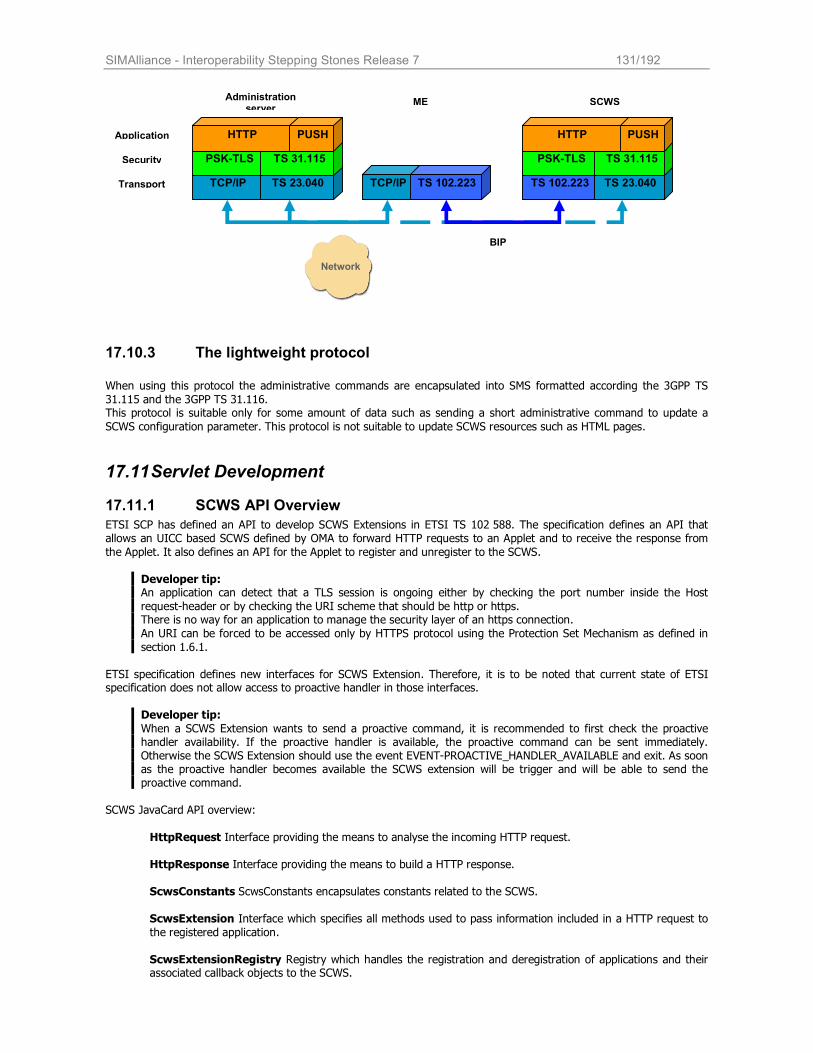
SIMAlliance - Interoperability Stepping Stones Release 7 131/192
17.10.3 The lightweight protocol
When using this protocol the administrative commands are encapsulated into SMS formatted according the 3GPP TS
31.115 and the 3GPP TS 31.116. This protocol is suitable only for some amount of data such as sending a short administrative command to update a
SCWS configuration parameter. This protocol is not suitable to update SCWS resources such as HTML pages.
17.11 Servlet Development
17.11.1 SCWS API Overview
ETSI SCP has defined an API to develop SCWS Extensions in ETSI TS 102 588. The specification defines an API that allows an UICC based SCWS defined by OMA to forward HTTP requests to an Applet and to receive the response from
the Applet. It also defines an API for the Applet to register and unregister to the SCWS.
Developer tip: An application can detect that a TLS session is ongoing either by checking the port number inside the Host
request-header or by checking the URI scheme that should be http or https. There is no way for an application to manage the security layer of an https connection.
An URI can be forced to be accessed only by HTTPS protocol using the Protection Set Mechanism as defined in
section 1.6.1.
ETSI specification defines new interfaces for SCWS Extension. Therefore, it is to be noted that current state of ETSI specification does not allow access to proactive handler in those interfaces.
Developer tip:
When a SCWS Extension wants to send a proactive command, it is recommended to first check the proactive handler availability. If the proactive handler is available, the proactive command can be sent immediately. Otherwise the SCWS Extension should use the event EVENT-PROACTIVE_HANDLER_AVAILABLE and exit. As soon as the proactive handler becomes available the SCWS extension will be trigger and will be able to send the proactive command.
SCWS JavaCard API overview:
HttpRequest Interface providing the means to analyse the incoming HTTP request.
HttpResponse Interface providing the means to build a HTTP response.
ScwsConstants ScwsConstants encapsulates constants related to the SCWS. ScwsExtension Interface which specifies all methods used to pass information included in a HTTP request to
the registered application.
ScwsExtensionRegistry Registry which handles the registration and deregistration of applications and their associated callback objects to the SCWS.
Application
Security
Transport TS 102.223 TCP/IP
PSK-TLS
Administration server
SCWS
TCP/IP TS 102.223
ME
BIP
TS 23.040
TS 31.115
HTTP PUSH
PSK-TLS
TS 23.040
TS 31.115
HTTP PUSH
Network
SIMAlliance - Interoperability Stepping Stones Release 7 132/192
ScwsExtensionService Class implementing the ScwsExtension interface.
ScwsException Smart Card Webserver exception and its associated constants.
17.11.2 Deployment of SCWS Extensions
A SCWS Extension is a standard javacard applet loaded using standard commands (Install for load, Load and Install for install). The SCWS Extension registers to the SCWS using an API of the SCWS framework. The SCWS Extension is not yet accessible. To become accessible a SCWS Extension shall be mapped to a URI by using the proper SCWS administrative command.
SIMAlliance - Interoperability Stepping Stones Release 7 133/192
18 Card Application Toolkit Transport Protocol (CAT_TP)
18.1 Scope The aim of this chapter is to give an overview of the BIP/CAT_TP technology. The CAT_TP protocol is defined in the ETSI TS 102 127. This protocol uses the BIP mechanism to exchange data between the ME and the card. The BIP mechanism is described in chapter 14.
According to the Release 6 of the specifications, this protocol can be used only by the RAM and RFM applications. No CAT_TP API is available in Release 6 for other applications in order to use this protocol. In the scope of the RFM and RAM applications, only the PUSH use case will be described, the OTA platform being at the origin of the data exchange request.
The way to initial a CAT_TP session using the PUSH command is defined in ETSI TS 102 226, the implementation over SMS is defined in the 3GPP TS 31 116. This particular mechanism is required because the card is the only entity being
able to open a BIP session with the UE and then to open a CAT-TP session.
• Interoperability Issue: The CAT_TP layer may not be implemented by all SIM Alliance members’ cards.
• ME required features: The CAT_TP protocol uses the BIP mechanism to exchange data between the UE and the card, the UE must be compliant to CAT class “e“ defined in ETSI TS 102 223.
18.2 Overview of CAT_TP
The CAT_TP protocol is a connection oriented and reliable end-to-end protocol between a remote entity (e.g. an OTA platform) and a card. The remote entity exchange data with the mobile equipment using the UDP protocol over the IP
network (e.g. the GPRS, EDGE or 3G network…). Then the mobile equipment exchanges data with the card using the BIP protocol.
The CAT_TP layer ensures the reliability of the exchange between the OTA platform and the card. It manages the connection, the flow control, the error detection and the data retransmission if needed. It allows the segmentation and
the re-assembly of data according to the capabilities of the different entities (OTA platform, ME and card).
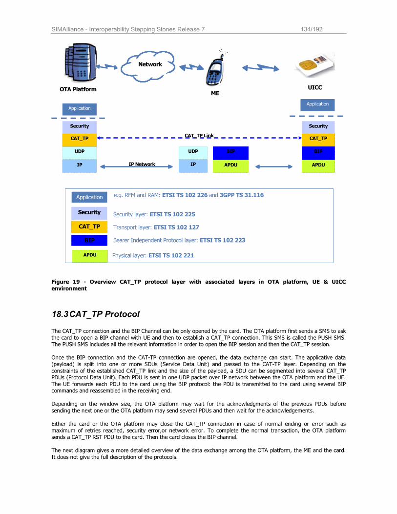
SIMAlliance - Interoperability Stepping Stones Release 7 134/192
BIP
APDU IP IP
UDP
CAT_TP
Application
Security
OTA Platform
Network
BIP
CAT_TP
Security Security layer: ETSI TS 102 225
Transport layer: ETSI TS 102 127
Bearer Independent Protocol layer: ETSI TS 102 223
Application e.g. RFM and RAM: ETSI TS 102 226 and 3GPP TS 31.116
UDP
CAT_TP
Application
Security
BIP
APDU
APDU Physical layer: ETSI TS 102 221
CAT_TP Link
UICC
IP Network
ME
Figure 19 - Overview CAT_TP protocol layer with associated layers in OTA platform, UE & UICC
environment
18.3 CAT_TP Protocol The CAT_TP connection and the BIP Channel can be only opened by the card. The OTA platform first sends a SMS to ask the card to open a BIP channel with UE and then to establish a CAT_TP connection. This SMS is called the PUSH SMS. The PUSH SMS includes all the relevant information in order to open the BIP session and then the CAT_TP session. Once the BIP connection and the CAT-TP connection are opened, the data exchange can start. The applicative data (payload) is split into one or more SDUs (Service Data Unit) and passed to the CAT-TP layer. Depending on the
constraints of the established CAT_TP link and the size of the payload, a SDU can be segmented into several CAT_TP PDUs (Protocol Data Unit). Each PDU is sent in one UDP packet over IP network between the OTA platform and the UE.
The UE forwards each PDU to the card using the BIP protocol: the PDU is transmitted to the card using several BIP commands and reassembled in the receiving end.
Depending on the window size, the OTA platform may wait for the acknowledgments of the previous PDUs before
sending the next one or the OTA platform may send several PDUs and then wait for the acknowledgements. Either the card or the OTA platform may close the CAT_TP connection in case of normal ending or error such as maximum of retries reached, security error,or network error. To complete the normal transaction, the OTA platform sends a CAT_TP RST PDU to the card. Then the card closes the BIP channel. The next diagram gives a more detailed overview of the data exchange among the OTA platform, the ME and the card.
It does not give the full description of the protocols.
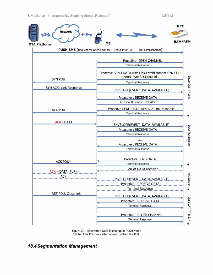
SIMAlliance - Interoperability Stepping Stones Release 7 135/192
OTA Platform
Network
Proactive SEND DATA with Link Establishment SYN PDU : ports, Max SDU,card id..
SYN ACK: Link Response
Proactive: OPEN CHANNEL
PUSH SMS (Request for Open Channel + Request for CAT_TP link establishment)
UICC
Terminal Response
SYN PDU
ENVELOPE(EVENT_DATA_AVAILABLE)
Proactive : RECEIVE DATA
Terminal Response
Terminal Response, SYN ACK
Proactive SEND DATA with ACK Link response
Terminal Response
ACK PDU
ACK - DATA ENVELOPE(EVENT_DATA_AVAILABLE)
Proactive : RECEIVE DATA
Terminal Response
……
ACK PDU*
ENVELOPE(EVENT_DATA_AVAILABLE) Proactive : RECEIVE DATA
Terminal Response
RST PDU, Close link
Proactive : CLOSE CHANNEL
Terminal Response
PoR of DATA received
RAM/RFM
Setup CAT_TP Link
Data Transm
ission
Close CAT_TP & BIP
Proactive : RECEIVE DATA
Terminal Response
ENVELOPE(EVENT_DATA_AVAILABLE)
Proactive : RECEIVE DATA
ACK
Terminal Response
PoR Sessio
n
Proactive SEND DATA
ACK – DATA (PoR)
ME
Terminal Response
Figure 20 - Illustration Data Exchange in PUSH mode *Note: This PDU may alternatively contain the PoR.
18.4 Segmentation Management
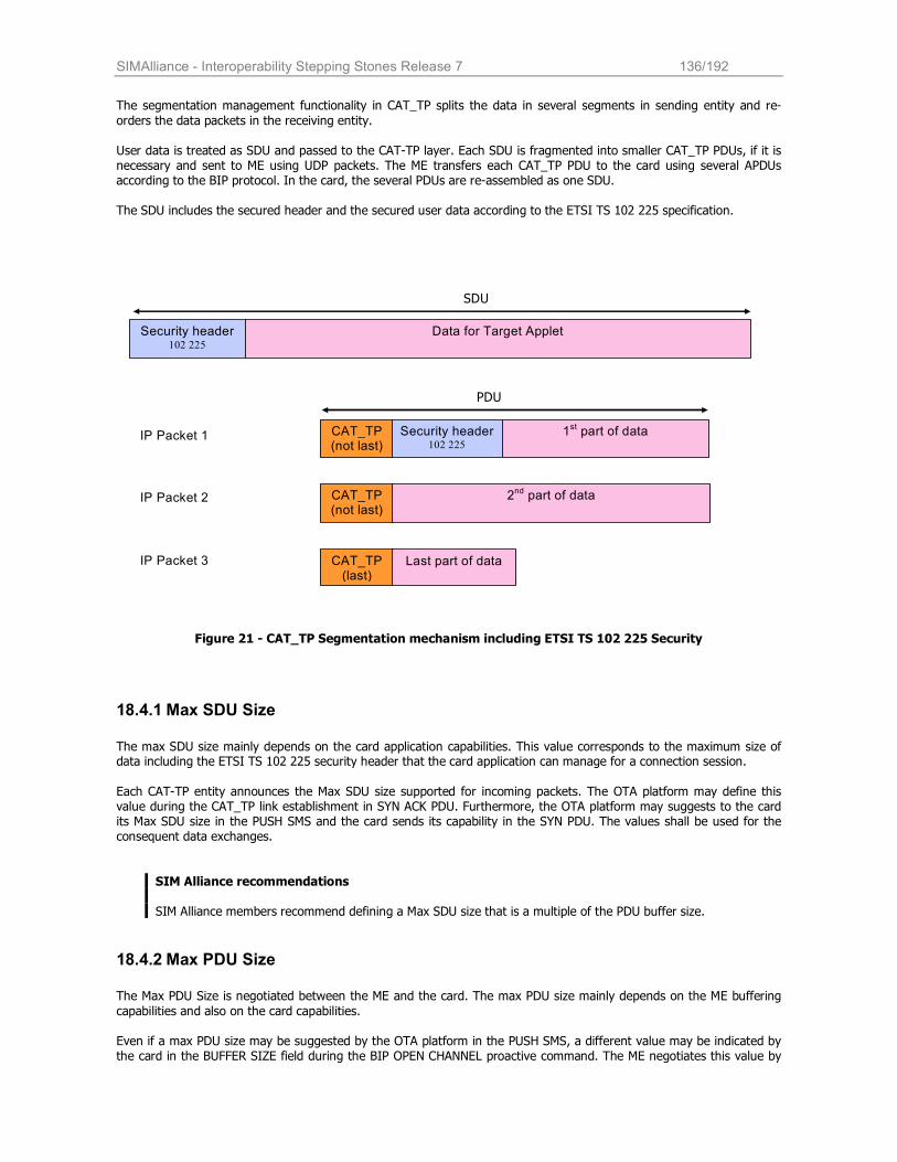
SIMAlliance - Interoperability Stepping Stones Release 7 136/192
The segmentation management functionality in CAT_TP splits the data in several segments in sending entity and re-
orders the data packets in the receiving entity.
User data is treated as SDU and passed to the CAT-TP layer. Each SDU is fragmented into smaller CAT_TP PDUs, if it is necessary and sent to ME using UDP packets. The ME transfers each CAT_TP PDU to the card using several APDUs according to the BIP protocol. In the card, the several PDUs are re-assembled as one SDU. The SDU includes the secured header and the secured user data according to the ETSI TS 102 225 specification.
Security header 102 225
Data for Target Applet
CAT_TP (not last)
Security header 102 225
1st part of data
CAT_TP (not last)
2nd part of data
CAT_TP (last)
Last part of data
IP Packet 1
IP Packet 2
IP Packet 3
SDU
PDU
Figure 21 - CAT_TP Segmentation mechanism including ETSI TS 102 225 Security
18.4.1 Max SDU Size
The max SDU size mainly depends on the card application capabilities. This value corresponds to the maximum size of data including the ETSI TS 102 225 security header that the card application can manage for a connection session.
Each CAT-TP entity announces the Max SDU size supported for incoming packets. The OTA platform may define this value during the CAT_TP link establishment in SYN ACK PDU. Furthermore, the OTA platform may suggests to the card its Max SDU size in the PUSH SMS and the card sends its capability in the SYN PDU. The values shall be used for the consequent data exchanges.
SIM Alliance recommendations SIM Alliance members recommend defining a Max SDU size that is a multiple of the PDU buffer size.
18.4.2 Max PDU Size
The Max PDU Size is negotiated between the ME and the card. The max PDU size mainly depends on the ME buffering
capabilities and also on the card capabilities. Even if a max PDU size may be suggested by the OTA platform in the PUSH SMS, a different value may be indicated by the card in the BUFFER SIZE field during the BIP OPEN CHANNEL proactive command. The ME negotiates this value by
SIMAlliance - Interoperability Stepping Stones Release 7 137/192
using the Terminal Response. The negotiated value is then sent back by the card to the OTA platform during the
CAT_TP link establishment.
The OTA platform announces its own max PDU size in the SYN ACK PDU. The 2 max PDU size values may be different.
SIM Alliance recommendations The ME is usually able to receive only one UDP packet. It is therefore recommended using a PDU size close to 1K
bytes.
18.5 Connection Management Some connection parameters can be set and negotiated through the PUSH mechanism or during the CAT_TP link establishment. Some are part of the card and server configurations.
18.5.1 CAT_TP Connection Ports
CAT_TP is a connection-oriented protocol with a full-duplex communication channel between two CAT_TP entities. CAT_TP PDUs from a sender are directed to a port on the destination entity. A connection is uniquely identified with
source and destination port identifiers and with the source and destination network identities.
Usually the OTA platform is used as a CAT_TP server receiving requests from the card that is a CAT_TP client. The CAT_TP port is used to address the applications running on top of CAT_TP. In the PUSH command ”Request for CAT_TP link establishment”, the OTA platform sends its port number (CAT_TP Destination Port object). The card application will use this port as a destination port for the following CAT_TP exchanges. The card application sends its own port in the CAT-TP Link Establishment command (source port object). This port will be used by the OTA platform as a destination port for the following data exchanges.
18.5.2 Identification Data
In order to link the exchanges over the IP network with the right card, the OTA platform need to identify the card using well-known card identifiers such as the card ICCID or the MSISDN. In the PUSH Command ”Request_for_CAT_TP_link_establishment”, the OTA platform can define a specific identifier (Identification data object). This value will be used by the card during the CAT_TP link establishment.
If the OTA platform doesn’t specify any value for the identifier (Identification data object) in the PUSH Command ”Request_for_CAT_TP_link_establishment”, the card uses its ICCID as identification data during the CAT-TP link
establishment.
18.5.3 Flow Control and Window Management
CAT_TP employs a simple flow control mechanism that is based on a window for the PDUs that the receiver is ready to accept. With each Acknowledgement Number, the acknowledging entity shall announce its current acceptance window. The sender is then allowed to send all PDUs within this window without receiving any new window announcement. The highest Sequence Number the sender is allowed to send data is calculated by adding the Window Size to the Acknowledgement Number of the last received PDU.
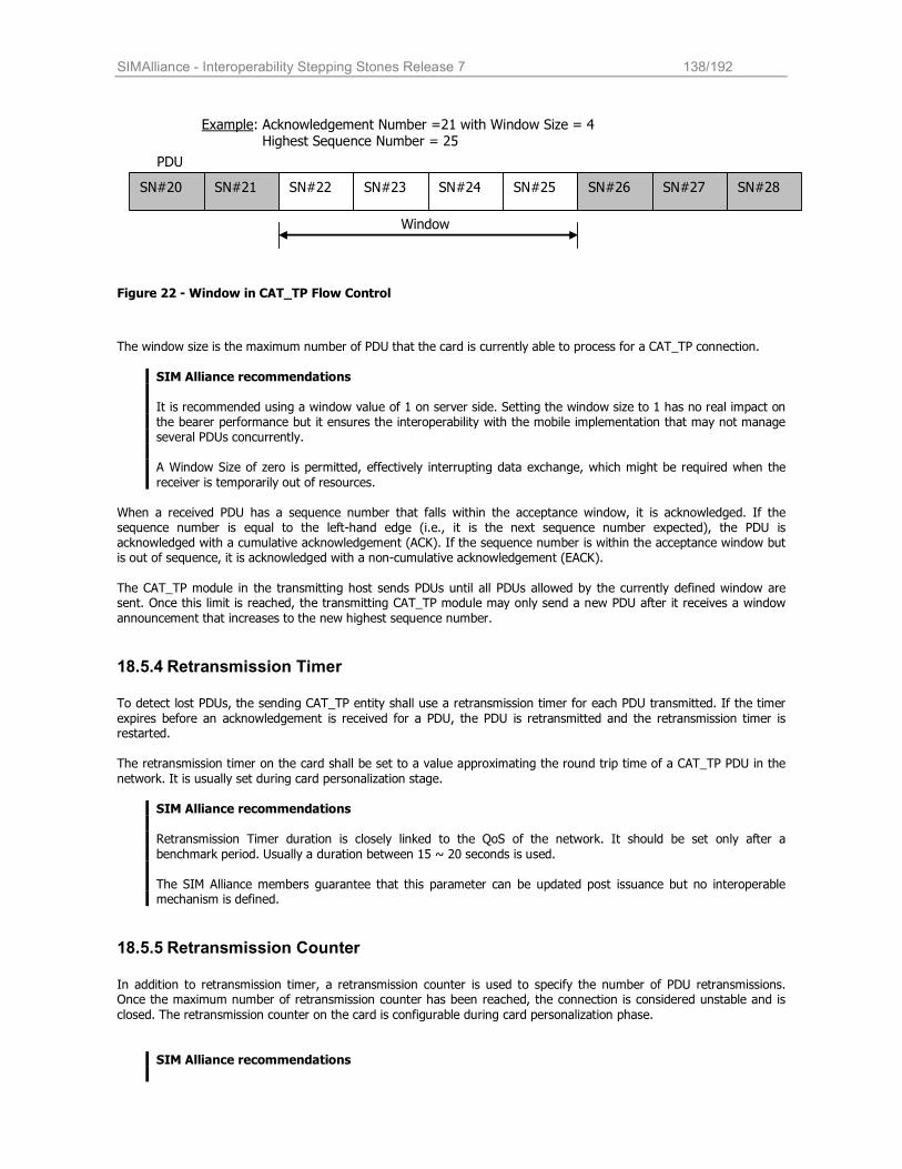
SIMAlliance - Interoperability Stepping Stones Release 7 138/192
SN#20 SN#21 SN#22 SN#23 SN#24 SN#25 SN#26 SN#27 SN#28
Example: Acknowledgement Number =21 with Window Size = 4 Highest Sequence Number = 25
Window
PDU
Figure 22 - Window in CAT_TP Flow Control
The window size is the maximum number of PDU that the card is currently able to process for a CAT_TP connection.
SIM Alliance recommendations It is recommended using a window value of 1 on server side. Setting the window size to 1 has no real impact on the bearer performance but it ensures the interoperability with the mobile implementation that may not manage several PDUs concurrently. A Window Size of zero is permitted, effectively interrupting data exchange, which might be required when the
receiver is temporarily out of resources.
When a received PDU has a sequence number that falls within the acceptance window, it is acknowledged. If the sequence number is equal to the left-hand edge (i.e., it is the next sequence number expected), the PDU is acknowledged with a cumulative acknowledgement (ACK). If the sequence number is within the acceptance window but is out of sequence, it is acknowledged with a non-cumulative acknowledgement (EACK).
The CAT_TP module in the transmitting host sends PDUs until all PDUs allowed by the currently defined window are sent. Once this limit is reached, the transmitting CAT_TP module may only send a new PDU after it receives a window
announcement that increases to the new highest sequence number.
18.5.4 Retransmission Timer
To detect lost PDUs, the sending CAT_TP entity shall use a retransmission timer for each PDU transmitted. If the timer
expires before an acknowledgement is received for a PDU, the PDU is retransmitted and the retransmission timer is restarted.
The retransmission timer on the card shall be set to a value approximating the round trip time of a CAT_TP PDU in the
network. It is usually set during card personalization stage.
SIM Alliance recommendations Retransmission Timer duration is closely linked to the QoS of the network. It should be set only after a
benchmark period. Usually a duration between 15 ~ 20 seconds is used.
The SIM Alliance members guarantee that this parameter can be updated post issuance but no interoperable mechanism is defined.
18.5.5 Retransmission Counter
In addition to retransmission timer, a retransmission counter is used to specify the number of PDU retransmissions. Once the maximum number of retransmission counter has been reached, the connection is considered unstable and is
closed. The retransmission counter on the card is configurable during card personalization phase.
SIM Alliance recommendations
SIMAlliance - Interoperability Stepping Stones Release 7 139/192
At least 1 retry of retransmission shall be considered.
The SIM Alliance members guarantee that this parameter can be updated post issuance but no interoperable
mechanism is defined.
18.5.6 CLOSE-WAIT Timer
Once a close request or a RST PDU has been received, the CAT_TP entity enters into an intermediate state CLOSE-WAIT. In this state, all the received PDUs are discarded. After a certain delay, the connection is terminated (CLOSE state). This delay time is called CLOSE-WAIT Timer.
SIM Alliance recommendations
This timer may not be supported by all card vendor’s CAT_TP implementations.
18.6 PUSH command The OTA platform sends PUSH commands using the SMS bearer to request the card to open a BIP channel and/or to
open a CAT-TP link. The 2 PUSH commands “Request for Open Channel” and “Request for CAT-TP link establishment” are defined in the ETSI TS 102 226.
The PUSH commands are inserted in a command script and sent using a SMS. Usually the 2 commands “Request for Open Channel” and “Request for CAT-TP link establishment” are inserted in the same command script, it may require concatenated SMS.
SIM Alliance recommendations
It is recommended to have the 2 commands “Request for Open Channel” and “Request for CAT-TP link establishment” in the same SMS.
18.6.1 PUSH command “Request for Open Channel”
The coding of the PUSH command is specified in the ETSI TS 102 226. This PUSH command may include all the fields required by the card to build the proactive command OPEN CHANNEL. The UICC may have default values for the
different fields. But if a field is defined in the PUSH command, its value takes precedence. This allows the operator to use different values than the default ones.
SIM Alliance recommendation: Presence and value of the default parameters used by the UICC can be specified at personalization time. The SIM Alliance members guarantee that these parameters can be updated post issuance but no interoperable mechanism is defined.
Furthermore, it is recommended that the OTA platform specifies most of the parameters required for the OPEN
CHANNEL especially the mandatory fields according to the ETSI TS 102 223 and not rely on the card default values that may be obsolete.
The SIM Alliance members recommend to not use the local address field.
Here is a short description of the most used fields in OPEN CHANNEL.
Field Description
Alpha identifier Define the sentence displayed by the ME during the user confirmation phase(*1).
Bearer description Define that the GPRS / 3G packet service will be used. Define the required Quality of Service (QoS). The description of the GPRS/3G packet service is given on the
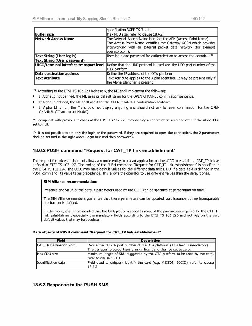
SIMAlliance - Interoperability Stepping Stones Release 7 140/192
specification 3GPP TS 31.111
Buffer size Max PDU size, refer to clause 18.4.2
Network Access Name The Network Access Name is in fact the APN (Access Point Name). The Access Point Name identifies the Gateway GGSN which provides interworking with an external packet data network (for example
operator.com). Text String (User login)
Text String (User password)
User login and password for authentication to access the domain. (*2)
UICC/terminal interface transport level Define that the UDP protocol is used and the UDP port number of the OTA platform
Data destination address Define the IP address of the OTA platform
Text Attribute Text Attribute applies to the Alpha Identifier. It may be present only if the Alpha Identifier is present.
(*1) According to the ETSI TS 102 223 Release 6, the ME shall implement the following:
• If Alpha Id not defined, the ME uses its default string for the OPEN CHANNEL confirmation sentence.
• If Alpha Id defined, the ME shall use it for the OPEN CHANNEL confirmation sentence.
• If Alpha Id is null, the ME should not display anything and should not ask for user confirmation for the OPEN CHANNEL (“Transparent Mode”)
ME compliant with previous releases of the ETSI TS 102 223 may display a confirmation sentence even if the Alpha Id is set to null. (*2) It is not possible to set only the login or the password, if they are required to open the connection, the 2 parameters shall be set and in the right order (login first and then password).
18.6.2 PUSH command “Request for CAT_TP link establishment”
The request for link establishment allows a remote entity to ask an application on the UICC to establish a CAT_TP link as defined in ETSI TS 102 127. The coding of the PUSH command “Request for CAT_TP link establishment” is specified in
the ETSI TS 102 226. The UICC may have default values for the different data fields. But if a data field is defined in the PUSH command, its value takes precedence. This allows the operator to use different values than the default ones.
SIM Alliance recommendation: Presence and value of the default parameters used by the UICC can be specified at personalization time. The SIM Alliance members guarantee that these parameters can be updated post issuance but no interoperable mechanism is defined.
Furthermore, it is recommended that the OTA platform specifies most of the parameters required for the CAT_TP link establishment especially the mandatory fields according to the ETSI TS 102 226 and not rely on the card
default values that may be obsolete.
Data objects of PUSH command “Request for CAT_TP link establishment”
Field Description
CAT_TP Destination Port Define the CAT-TP port number of the OTA platform. (This field is mandatory). The transport protocol type is insignificant and shall be set to zero.
Max SDU size Maximum length of SDU suggested by the OTA platform to be used by the card,
refer to clause 18.4.1.
Identification data Field used to uniquely identify the card (e.g. MSISDN, ICCID), refer to clause 18.5.2
18.6.3 Response to the PUSH SMS
SIMAlliance - Interoperability Stepping Stones Release 7 141/192
It is possible to ask for a response packet to get the result of the process of the PUSH commands (the OPEN_CHANNEL
and/or the CAT_TP link establishment). The response is sent when a PoR is requested in the PUSH SMS, it is mandatory to use the mode “PoR response sent using SMS_SUBMIT”.
The support of the additional response data is optional. The SIM Alliance members guarantee that they all manage the additional response data. The coding of the response data is defined in the ETSI TS 102 226.
SIM Alliance recommendation concerning PoR management:
The PoR is only interesting in case of PUSH “Request for Open Channel” or “Request for CAT-TP link
establishment” failure or other security errors (ETSI TS 102 225). If the PUSH SMS requests succeed, the OTA platform is already aware of it as the link is open. The sending of the PoR once the channel and the link are
established may disturb the communication between the ME and the card. It is recommended to send the PUSH SMS without requesting a PoR. If the link establishment fails, the OTA platform can send a second PUSH SMS requesting a PoR (using SMS-SUBMIT) to retrieve the error cause.
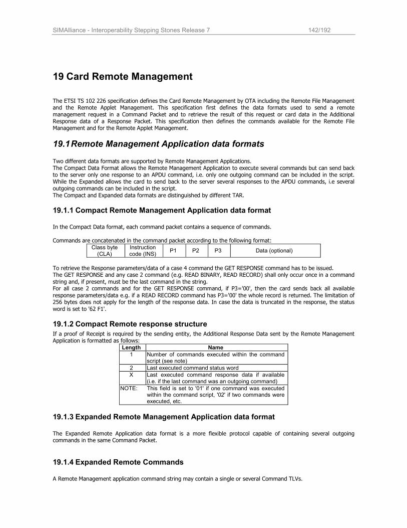
SIMAlliance - Interoperability Stepping Stones Release 7 142/192
19 Card Remote Management
The ETSI TS 102 226 specification defines the Card Remote Management by OTA including the Remote File Management and the Remote Applet Management. This specification first defines the data formats used to send a remote
management request in a Command Packet and to retrieve the result of this request or card data in the Additional Response data of a Response Packet. This specification then defines the commands available for the Remote File Management and for the Remote Applet Management.
19.1 Remote Management Application data formats Two different data formats are supported by Remote Management Applications. The Compact Data Format allows the Remote Management Application to execute several commands but can send back to the server only one response to an APDU command, i.e. only one outgoing command can be included in the script. While the Expanded allows the card to send back to the server several responses to the APDU commands, i.e several outgoing commands can be included in the script.
The Compact and Expanded data formats are distinguished by different TAR.
19.1.1 Compact Remote Management Application data format
In the Compact Data format, each command packet contains a sequence of commands. Commands are concatenated in the command packet according to the following format:
Class byte (CLA)
Instruction code (INS)
P1 P2 P3 Data (optional)
To retrieve the Response parameters/data of a case 4 command the GET RESPONSE command has to be issued. The GET RESPONSE and any case 2 command (e.g. READ BINARY, READ RECORD) shall only occur once in a command
string and, if present, must be the last command in the string. For all case 2 commands and for the GET RESPONSE command, if P3='00', then the card sends back all available
response parameters/data e.g. if a READ RECORD command has P3='00' the whole record is returned. The limitation of 256 bytes does not apply for the length of the response data. In case the data is truncated in the response, the status
word is set to '62 F1'.
19.1.2 Compact Remote response structure
If a proof of Receipt is required by the sending entity, the Additional Response Data sent by the Remote Management Application is formatted as follows:
Length Name
1 Number of commands executed within the command script (see note)
2 Last executed command status word
X Last executed command response data if available (i.e. if the last command was an outgoing command)
NOTE: This field is set to '01' if one command was executed within the command script, '02' if two commands were executed, etc.
19.1.3 Expanded Remote Management Application data format
The Expanded Remote Application data format is a more flexible protocol capable of containing several outgoing commands in the same Command Packet.
19.1.4 Expanded Remote Commands
A Remote Management application command string may contain a single or several Command TLVs.
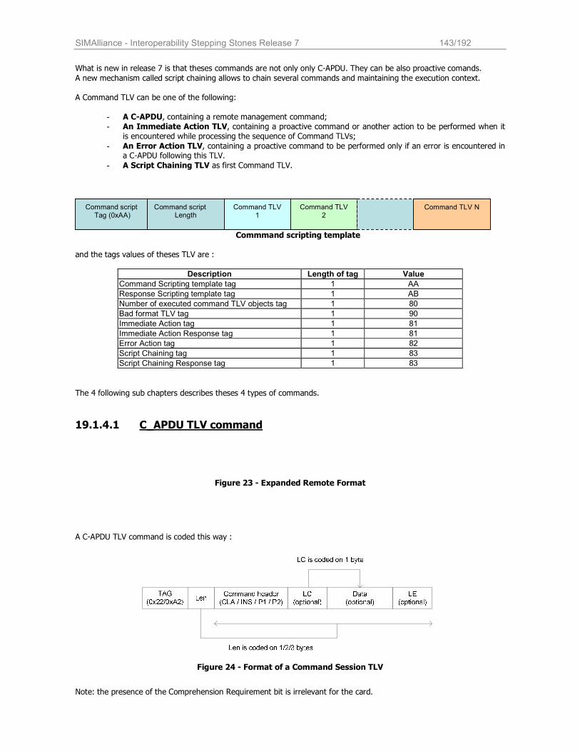
SIMAlliance - Interoperability Stepping Stones Release 7 143/192
What is new in release 7 is that theses commands are not only only C-APDU. They can be also proactive comands.
A new mechanism called script chaining allows to chain several commands and maintaining the execution context.
A Command TLV can be one of the following:
- A C-APDU, containing a remote management command; - An Immediate Action TLV, containing a proactive command or another action to be performed when it
is encountered while processing the sequence of Command TLVs;
- An Error Action TLV, containing a proactive command to be performed only if an error is encountered in a C-APDU following this TLV.
- A Script Chaining TLV as first Command TLV.
Commmand scripting template and the tags values of theses TLV are :
Description Length of tag Value
Command Scripting template tag 1 AA
Response Scripting template tag 1 AB
Number of executed command TLV objects tag 1 80
Bad format TLV tag 1 90
Immediate Action tag 1 81
Immediate Action Response tag 1 81
Error Action tag 1 82
Script Chaining tag 1 83
Script Chaining Response tag 1 83
The 4 following sub chapters describes theses 4 types of commands.
19.1.4.1 C_APDU TLV command
Figure 23 - Expanded Remote Format
A C-APDU TLV command is coded this way :
Figure 24 - Format of a Command Session TLV
Note: the presence of the Comprehension Requirement bit is irrelevant for the card.
Command script Tag (0xAA)
Command script Length
Command TLV 1
Command TLV 2
Command TLV N
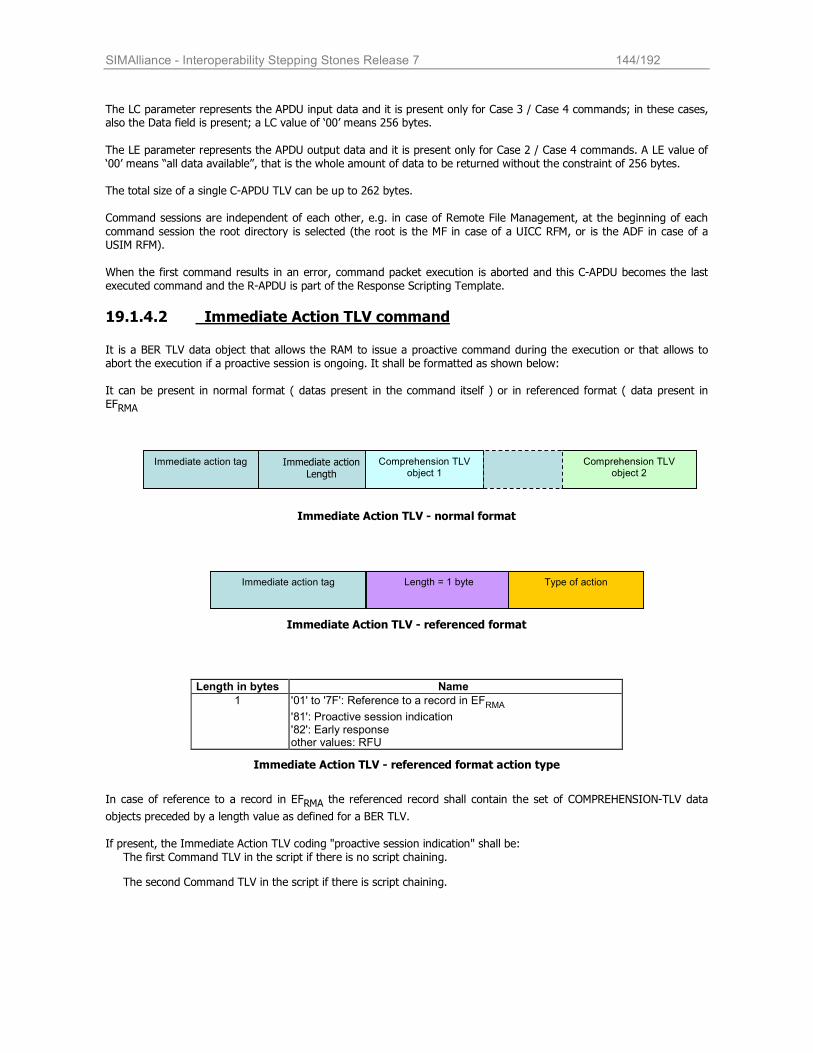
SIMAlliance - Interoperability Stepping Stones Release 7 144/192
The LC parameter represents the APDU input data and it is present only for Case 3 / Case 4 commands; in these cases, also the Data field is present; a LC value of ‘00’ means 256 bytes.
The LE parameter represents the APDU output data and it is present only for Case 2 / Case 4 commands. A LE value of ‘00’ means “all data available”, that is the whole amount of data to be returned without the constraint of 256 bytes. The total size of a single C-APDU TLV can be up to 262 bytes.
Command sessions are independent of each other, e.g. in case of Remote File Management, at the beginning of each
command session the root directory is selected (the root is the MF in case of a UICC RFM, or is the ADF in case of a USIM RFM).
When the first command results in an error, command packet execution is aborted and this C-APDU becomes the last executed command and the R-APDU is part of the Response Scripting Template.
19.1.4.2 Immediate Action TLV command
It is a BER TLV data object that allows the RAM to issue a proactive command during the execution or that allows to abort the execution if a proactive session is ongoing. It shall be formatted as shown below:
It can be present in normal format ( datas present in the command itself ) or in referenced format ( data present in EFRMA
Immediate Action TLV - normal format
Immediate Action TLV - referenced format
Length in bytes Name
1 '01' to '7F': Reference to a record in EFRMA
'81': Proactive session indication '82': Early response other values: RFU
Immediate Action TLV - referenced format action type
In case of reference to a record in EFRMA the referenced record shall contain the set of COMPREHENSION-TLV data
objects preceded by a length value as defined for a BER TLV.
If present, the Immediate Action TLV coding "proactive session indication" shall be: The first Command TLV in the script if there is no script chaining.
The second Command TLV in the script if there is script chaining.
Immediate action tag Immediate action Length
Comprehension TLV object 1 Comprehension TLV
object 2
Immediate action tag Length = 1 byte
Type of action
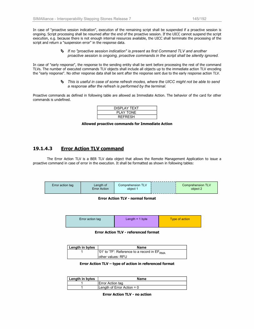
SIMAlliance - Interoperability Stepping Stones Release 7 145/192
In case of "proactive session indication", execution of the remaining script shall be suspended if a proactive session is
ongoing. Script processing shall be resumed after the end of the proactive session. If the UICC cannot suspend the script execution, e.g. because there is not enough internal resources available, the UICC shall terminate the processing of the
script and return a "suspension error" in the response data.
���� If no "proactive session indication" is present as first Command TLV and another proactive session is ongoing, proactive commands in the script shall be silently ignored.
In case of "early response", the response to the sending entity shall be sent before processing the rest of the command TLVs. The number of executed commands TLV objects shall include all objects up to the immediate action TLV encoding
the "early response". No other response data shall be sent after the response sent due to the early response action TLV.
���� This is useful in case of some refresh modes, where the UICC might not be able to send a response after the refresh is performed by the terminal.
Proactive commands as defined in following table are allowed as Immediate Action. The behavior of the card for other
commands is undefined.
DISPLAY TEXT
PLAY TONE
REFRESH
Allowed proactive commands for Immediate Action
19.1.4.3 Error Action TLV command
The Error Action TLV is a BER TLV data object that allows the Remote Management Application to issue a
proactive command in case of error in the execution. It shall be formatted as shown in following tables:
Error Action TLV - normal format
Error Action TLV - referenced format
Length in bytes Name
1 '01' to '7F': Reference to a record in EFRMA other values: RFU
Error Action TLV – type of action in referenced format
Length in bytes Name
1 Error Action tag
1 Length of Error Action = 0
Error Action TLV - no action
Error action tag Length = 1 byte
Type of action
Error action tag Length of Error Action
Comprehension TLV
object 1 Comprehension TLV
object 2
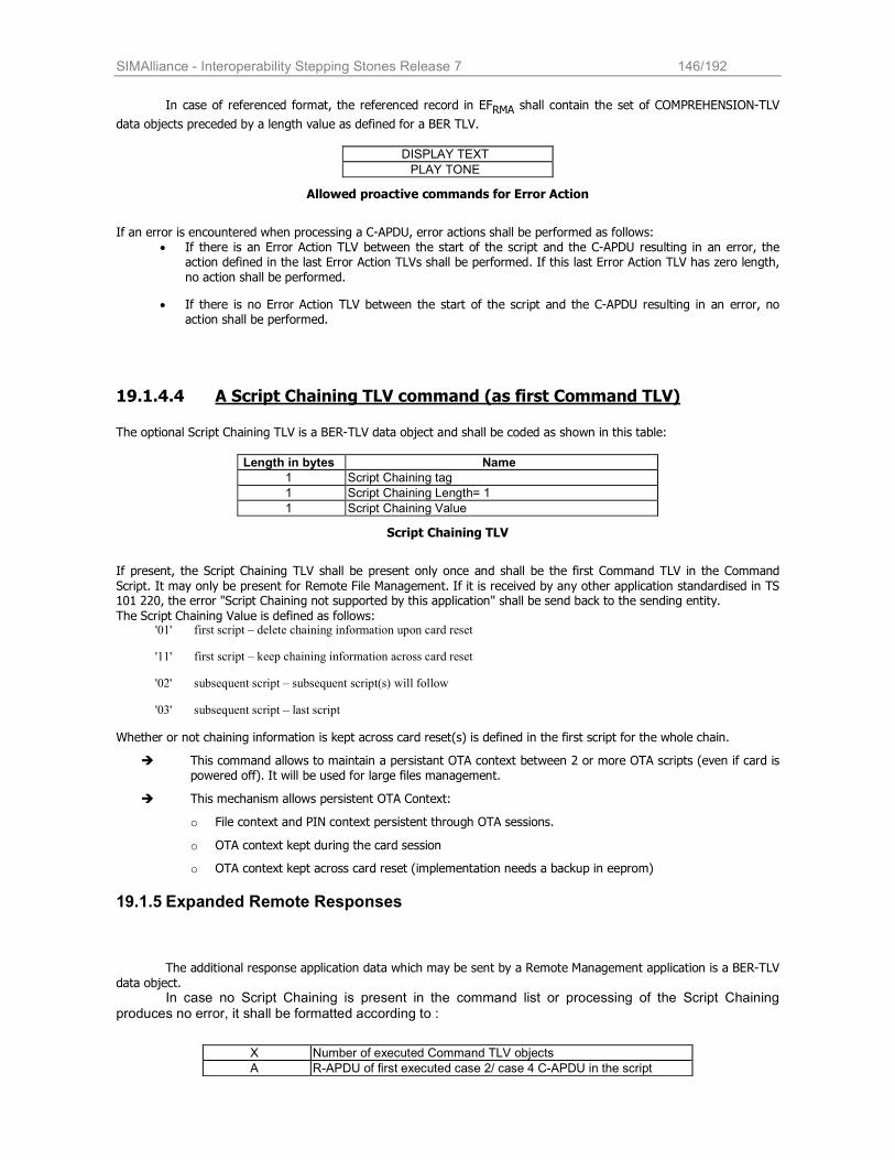
SIMAlliance - Interoperability Stepping Stones Release 7 146/192
In case of referenced format, the referenced record in EFRMA shall contain the set of COMPREHENSION-TLV
data objects preceded by a length value as defined for a BER TLV.
DISPLAY TEXT
PLAY TONE
Allowed proactive commands for Error Action
If an error is encountered when processing a C-APDU, error actions shall be performed as follows:
• If there is an Error Action TLV between the start of the script and the C-APDU resulting in an error, the action defined in the last Error Action TLVs shall be performed. If this last Error Action TLV has zero length,
no action shall be performed.
• If there is no Error Action TLV between the start of the script and the C-APDU resulting in an error, no action shall be performed.
19.1.4.4 A Script Chaining TLV command (as first Command TLV) The optional Script Chaining TLV is a BER-TLV data object and shall be coded as shown in this table:
Length in bytes Name
1 Script Chaining tag
1 Script Chaining Length= 1
1 Script Chaining Value
Script Chaining TLV
If present, the Script Chaining TLV shall be present only once and shall be the first Command TLV in the Command
Script. It may only be present for Remote File Management. If it is received by any other application standardised in TS 101 220, the error "Script Chaining not supported by this application" shall be send back to the sending entity.
The Script Chaining Value is defined as follows: '01' first script – delete chaining information upon card reset
'11' first script – keep chaining information across card reset
'02' subsequent script – subsequent script(s) will follow
'03' subsequent script – last script
Whether or not chaining information is kept across card reset(s) is defined in the first script for the whole chain.
� This command allows to maintain a persistant OTA context between 2 or more OTA scripts (even if card is powered off). It will be used for large files management.
� This mechanism allows persistent OTA Context:
o File context and PIN context persistent through OTA sessions.
o OTA context kept during the card session
o OTA context kept across card reset (implementation needs a backup in eeprom)
19.1.5 Expanded Remote Responses
The additional response application data which may be sent by a Remote Management application is a BER-TLV
data object. In case no Script Chaining is present in the command list or processing of the Script Chaining
produces no error, it shall be formatted according to :
X Number of executed Command TLV objects
A R-APDU of first executed case 2/ case 4 C-APDU in the script
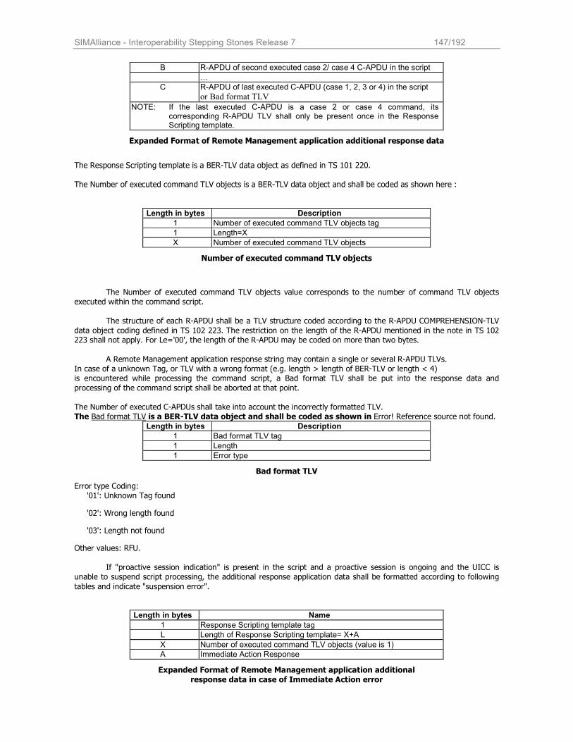
SIMAlliance - Interoperability Stepping Stones Release 7 147/192
B R-APDU of second executed case 2/ case 4 C-APDU in the script
…
C R-APDU of last executed C-APDU (case 1, 2, 3 or 4) in the script
or Bad format TLV
NOTE: If the last executed C-APDU is a case 2 or case 4 command, its corresponding R-APDU TLV shall only be present once in the Response Scripting template.
Expanded Format of Remote Management application additional response data
The Response Scripting template is a BER-TLV data object as defined in TS 101 220. The Number of executed command TLV objects is a BER-TLV data object and shall be coded as shown here :
Length in bytes Description
1 Number of executed command TLV objects tag
1 Length=X
X Number of executed command TLV objects
Number of executed command TLV objects
The Number of executed command TLV objects value corresponds to the number of command TLV objects
executed within the command script. The structure of each R-APDU shall be a TLV structure coded according to the R-APDU COMPREHENSION-TLV
data object coding defined in TS 102 223. The restriction on the length of the R-APDU mentioned in the note in TS 102 223 shall not apply. For Le='00', the length of the R-APDU may be coded on more than two bytes.
A Remote Management application response string may contain a single or several R-APDU TLVs.
In case of a unknown Tag, or TLV with a wrong format (e.g. length > length of BER-TLV or length < 4) is encountered while processing the command script, a Bad format TLV shall be put into the response data and processing of the command script shall be aborted at that point. The Number of executed C-APDUs shall take into account the incorrectly formatted TLV. The Bad format TLV is a BER-TLV data object and shall be coded as shown in Error! Reference source not found.
Length in bytes Description
1 Bad format TLV tag
1 Length
1 Error type
Bad format TLV
Error type Coding: '01': Unknown Tag found
'02': Wrong length found
'03': Length not found
Other values: RFU.
If "proactive session indication" is present in the script and a proactive session is ongoing and the UICC is unable to suspend script processing, the additional response application data shall be formatted according to following
tables and indicate "suspension error".
Length in bytes Name
1 Response Scripting template tag
L Length of Response Scripting template= X+A
X Number of executed command TLV objects (value is 1)
A Immediate Action Response
Expanded Format of Remote Management application additional
response data in case of Immediate Action error
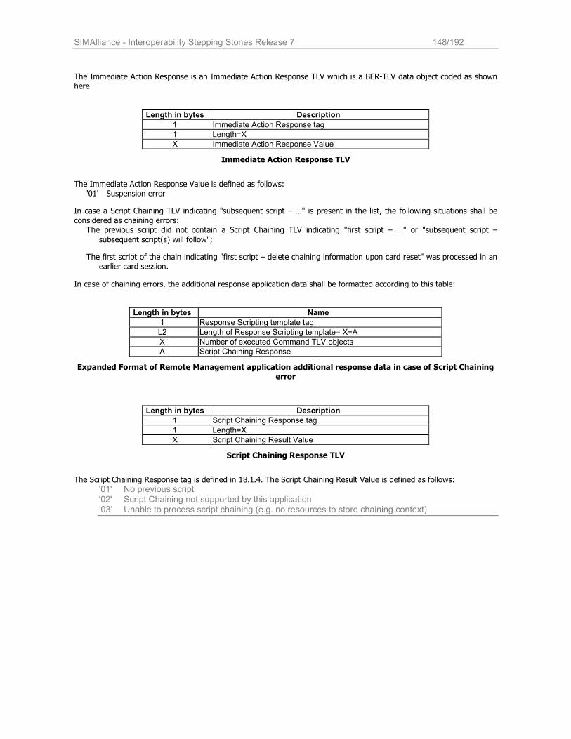
SIMAlliance - Interoperability Stepping Stones Release 7 148/192
The Immediate Action Response is an Immediate Action Response TLV which is a BER-TLV data object coded as shown here
Length in bytes Description
1 Immediate Action Response tag
1 Length=X
X Immediate Action Response Value
Immediate Action Response TLV
The Immediate Action Response Value is defined as follows:
'01' Suspension error
In case a Script Chaining TLV indicating "subsequent script – …" is present in the list, the following situations shall be
considered as chaining errors: The previous script did not contain a Script Chaining TLV indicating "first script – …" or "subsequent script –
subsequent script(s) will follow";
The first script of the chain indicating "first script – delete chaining information upon card reset" was processed in an earlier card session.
In case of chaining errors, the additional response application data shall be formatted according to this table:
Length in bytes Name
1 Response Scripting template tag
L2 Length of Response Scripting template= X+A
X Number of executed Command TLV objects
A Script Chaining Response
Expanded Format of Remote Management application additional response data in case of Script Chaining error
Length in bytes Description
1 Script Chaining Response tag
1 Length=X
X Script Chaining Result Value
Script Chaining Response TLV
The Script Chaining Response tag is defined in 18.1.4. The Script Chaining Result Value is defined as follows:
'01' No previous script '02' Script Chaining not supported by this application ‘03’ Unable to process script chaining (e.g. no resources to store chaining context)
SIMAlliance - Interoperability Stepping Stones Release 7 149/192
20 Remote File Management Architecture
Remote file management applications on the UICC/USIM provide Remote file access in accordance to the new
UICC/USIM architecture.
20.1 Remote File Access for UICC If an application provides access to the shared file system structure over the air, it is called “UICC Shared File System Remote File Management” (UICC RFM). It allows file management of the EFs and the DFs stored under the MF, but it can not access any ADF so the execution of Select by path or Select by FID with File IDentifier ‘7FFF’ contained in the Command Data fails. Select by name is also not supported.
Unless Script Chaining is used, the MF shall be implicitly selected and be the current directory at the beginning of a Command "session".
20.2 Remote File Access for ADF As on the card several applications can be present, each of them is the owner and the manager of a different ADF. There can be also several RFM applications to manage ADF via OTA. Each RFM application is also able to manage the EFs and DFs under the MF. The implicitly selected ADF is the current directory at the beginning of a Command "session". It is possible to reselect the ADF root from another DF by using the FID ‘7FFF’. With an USIM RFM it is not possible to access files stored under other ADFs (e.g. another USIM).
Unless Script Chaining is used, the ADF shall be implicitly selected and be the current directory at the beginning of a Command "session".
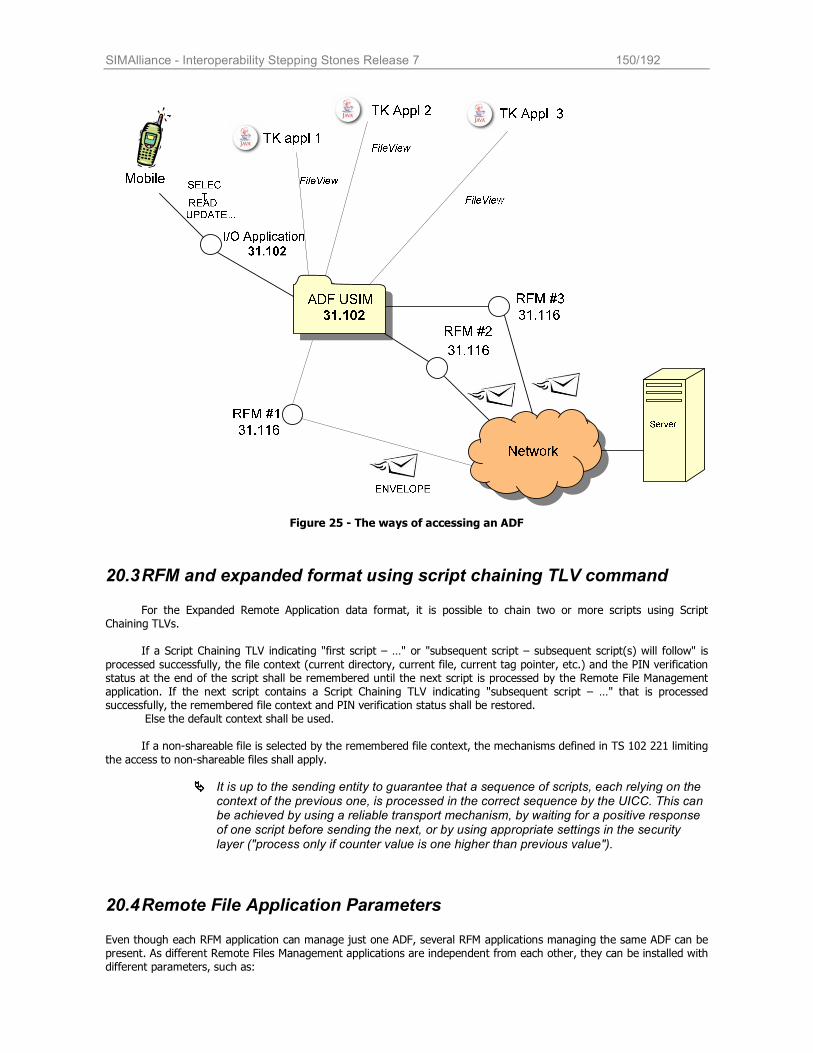
SIMAlliance - Interoperability Stepping Stones Release 7 150/192
Figure 25 - The ways of accessing an ADF
20.3 RFM and expanded format using script chaining TLV command
For the Expanded Remote Application data format, it is possible to chain two or more scripts using Script Chaining TLVs.
If a Script Chaining TLV indicating "first script – …" or "subsequent script – subsequent script(s) will follow" is
processed successfully, the file context (current directory, current file, current tag pointer, etc.) and the PIN verification status at the end of the script shall be remembered until the next script is processed by the Remote File Management application. If the next script contains a Script Chaining TLV indicating "subsequent script – …" that is processed successfully, the remembered file context and PIN verification status shall be restored.
Else the default context shall be used.
If a non-shareable file is selected by the remembered file context, the mechanisms defined in TS 102 221 limiting
the access to non-shareable files shall apply.
���� It is up to the sending entity to guarantee that a sequence of scripts, each relying on the context of the previous one, is processed in the correct sequence by the UICC. This can be achieved by using a reliable transport mechanism, by waiting for a positive response of one script before sending the next, or by using appropriate settings in the security layer ("process only if counter value is one higher than previous value").
20.4 Remote File Application Parameters Even though each RFM application can manage just one ADF, several RFM applications managing the same ADF can be present. As different Remote Files Management applications are independent from each other, they can be installed with different parameters, such as:
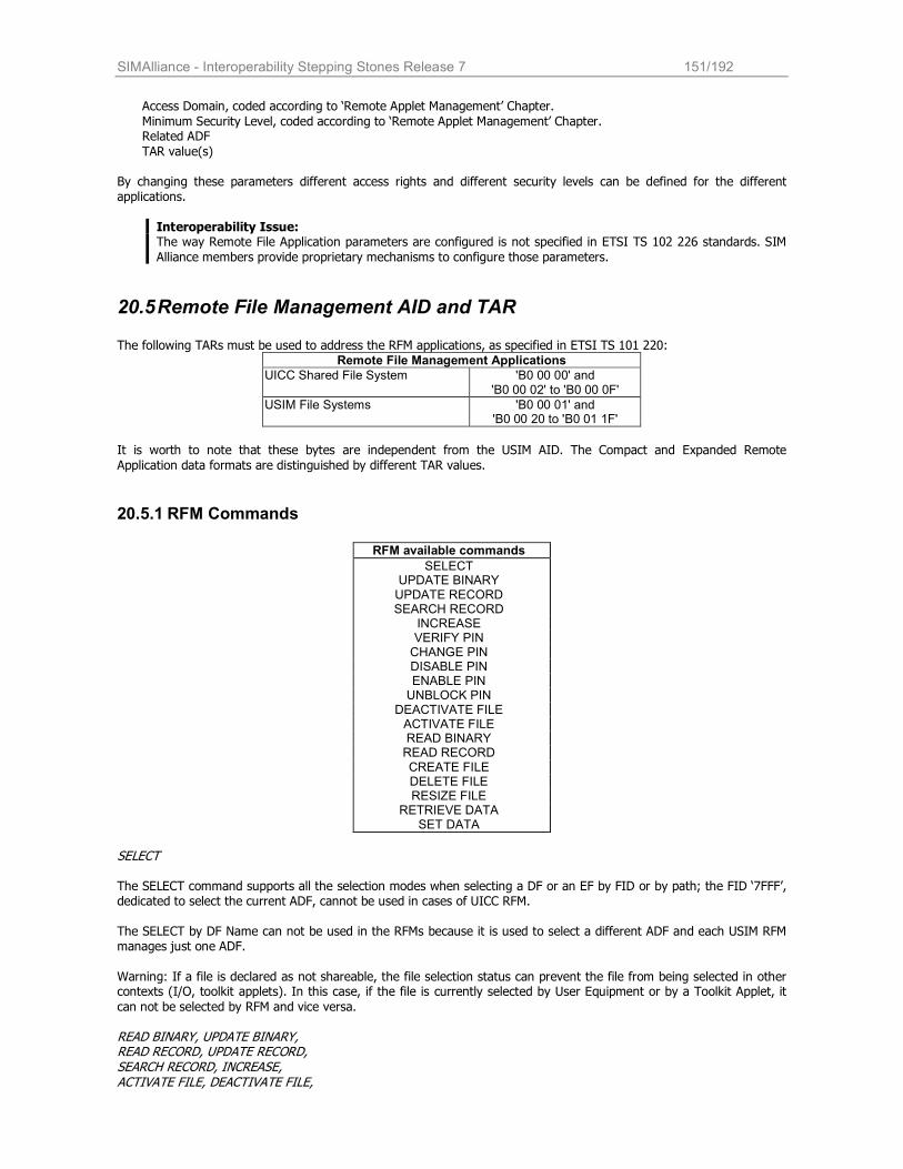
SIMAlliance - Interoperability Stepping Stones Release 7 151/192
Access Domain, coded according to ‘Remote Applet Management’ Chapter.
Minimum Security Level, coded according to ‘Remote Applet Management’ Chapter. Related ADF
TAR value(s) By changing these parameters different access rights and different security levels can be defined for the different applications.
Interoperability Issue: The way Remote File Application parameters are configured is not specified in ETSI TS 102 226 standards. SIM
Alliance members provide proprietary mechanisms to configure those parameters.
20.5 Remote File Management AID and TAR The following TARs must be used to address the RFM applications, as specified in ETSI TS 101 220:
Remote File Management Applications
UICC Shared File System 'B0 00 00' and 'B0 00 02' to 'B0 00 0F'
USIM File Systems 'B0 00 01' and 'B0 00 20 to 'B0 01 1F'
It is worth to note that these bytes are independent from the USIM AID. The Compact and Expanded Remote
Application data formats are distinguished by different TAR values.
20.5.1 RFM Commands
RFM available commands
SELECT UPDATE BINARY UPDATE RECORD SEARCH RECORD
INCREASE VERIFY PIN CHANGE PIN DISABLE PIN ENABLE PIN UNBLOCK PIN
DEACTIVATE FILE ACTIVATE FILE READ BINARY READ RECORD CREATE FILE DELETE FILE RESIZE FILE
RETRIEVE DATA SET DATA
SELECT The SELECT command supports all the selection modes when selecting a DF or an EF by FID or by path; the FID ‘7FFF’, dedicated to select the current ADF, cannot be used in cases of UICC RFM. The SELECT by DF Name can not be used in the RFMs because it is used to select a different ADF and each USIM RFM manages just one ADF.
Warning: If a file is declared as not shareable, the file selection status can prevent the file from being selected in other contexts (I/O, toolkit applets). In this case, if the file is currently selected by User Equipment or by a Toolkit Applet, it
can not be selected by RFM and vice versa.
READ BINARY, UPDATE BINARY, READ RECORD, UPDATE RECORD, SEARCH RECORD, INCREASE, ACTIVATE FILE, DEACTIVATE FILE,
SIMAlliance - Interoperability Stepping Stones Release 7 152/192
CREATE FILE, DELETE FILE, RESIZE FILE The operations are allowed only if a Security Condition (SC) related to the relevant Access Mode (AM) is granted by the
RFM application Access Domain. The access rights granted to an application by its Access Domain is independent from the access rights granted at the UICC/Terminal interface. This implies in particular that the status of a secret code (e.g. disabled PIN1, blocked PIN2, etc.) at the UICC/Terminal interface does not affect the access rights granted to an application.
Security Condition and Access Mode are indicated in EFARR (see ETSI TS 102 221).
VERIFY PIN, CHANGE PIN, ENABLE PIN, DISABLE PIN, UNBLOCK PIN
The PIN related commands affect the PIN value or the PIN blocking status both in RFM sessions and in I/O sessions: presenting a wrong PIN value for three times, the PIN is blocked also for the I/O session; changing PIN value via OTA affects PIN value also for the I/O session, and so onInteroperability Issue: SIM Alliance members are not interoperable about the PIN verification during an OTA sessions: it may or may not change the set of operations granted to the RFM application in the current session.
SET_DATA & RETRIEVE_DATA Added to access larges files in read\write operations.
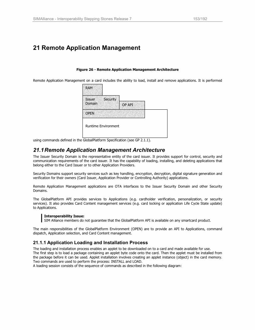
SIMAlliance - Interoperability Stepping Stones Release 7 153/192
21 Remote Application Management
Figure 26 - Remote Application Management Architecture
Remote Application Management on a card includes the ability to load, install and remove applications. It is performed
using commands defined in the GlobalPlatform Specification (see GP 2.1.1).
21.1 Remote Application Management Architecture The Issuer Security Domain is the representative entity of the card issuer. It provides support for control, security and communication requirements of the card issuer. It has the capability of loading, installing, and deleting applications that
belong either to the Card Issuer or to other Application Providers.
Security Domains support security services such as key handling, encryption, decryption, digital signature generation and verification for their owners (Card Issuer, Application Provider or Controlling Authority) applications.
Remote Application Management applications are OTA interfaces to the Issuer Security Domain and other Security Domains.
The GlobalPlatform API provides services to Applications (e.g. cardholder verification, personalization, or security
services). It also provides Card Content management services (e.g. card locking or application Life Cycle State update) to Applications.
Interoperability Issue:
SIM Alliance members do not guarantee that the GlobalPlatform API is available on any smartcard product. The main responsibilities of the GlobalPlatform Environment (OPEN) are to provide an API to Applications, command dispatch, Application selection, and Card Content management.
21.1.1 Application Loading and Installation Process
The loading and installation process enables an applet to be downloaded on to a card and made available for use. The first step is to load a package containing an applet byte code onto the card. Then the applet must be installed from
the package before it can be used. Applet installation involves creating an applet instance (object) in the card memory. Two commands are used to perform the process: INSTALL and LOAD. A loading session consists of the sequence of commands as described in the following diagram:
Runtime Environment
Issuer Security Domain
RAM
OPEN
OP API
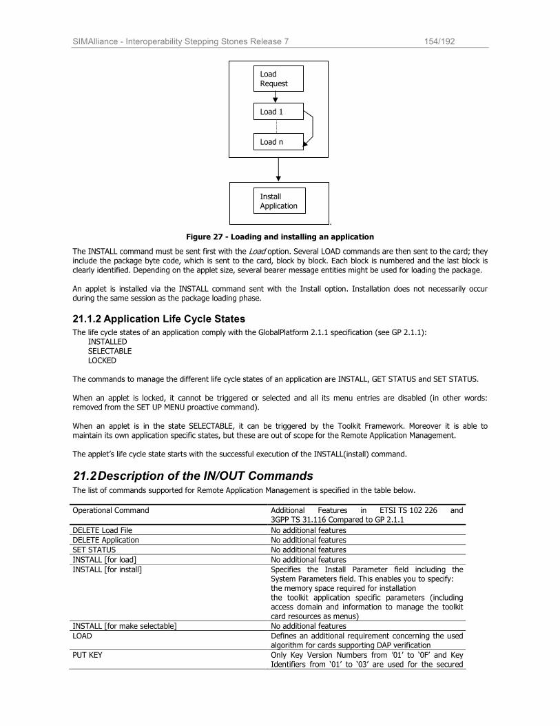
SIMAlliance - Interoperability Stepping Stones Release 7 154/192
.
Figure 27 - Loading and installing an application
The INSTALL command must be sent first with the Load option. Several LOAD commands are then sent to the card; they include the package byte code, which is sent to the card, block by block. Each block is numbered and the last block is clearly identified. Depending on the applet size, several bearer message entities might be used for loading the package. An applet is installed via the INSTALL command sent with the Install option. Installation does not necessarily occur during the same session as the package loading phase.
21.1.2 Application Life Cycle States
The life cycle states of an application comply with the GlobalPlatform 2.1.1 specification (see GP 2.1.1): INSTALLED SELECTABLE LOCKED
The commands to manage the different life cycle states of an application are INSTALL, GET STATUS and SET STATUS.
When an applet is locked, it cannot be triggered or selected and all its menu entries are disabled (in other words: removed from the SET UP MENU proactive command).
When an applet is in the state SELECTABLE, it can be triggered by the Toolkit Framework. Moreover it is able to maintain its own application specific states, but these are out of scope for the Remote Application Management. The applet’s life cycle state starts with the successful execution of the INSTALL(install) command.
21.2 Description of the IN/OUT Commands The list of commands supported for Remote Application Management is specified in the table below.
Operational Command Additional Features in ETSI TS 102 226 and 3GPP TS 31.116 Compared to GP 2.1.1
DELETE Load File No additional features
DELETE Application No additional features
SET STATUS No additional features
INSTALL [for load] No additional features
INSTALL [for install] Specifies the Install Parameter field including the System Parameters field. This enables you to specify: the memory space required for installation the toolkit application specific parameters (including access domain and information to manage the toolkit card resources as menus)
INSTALL [for make selectable] No additional features
LOAD Defines an additional requirement concerning the used algorithm for cards supporting DAP verification
PUT KEY Only Key Version Numbers from ’01’ to ‘0F’ and Key Identifiers from ‘01’ to ‘03’ are used for the secured
Load
Request
Load 1
Load n
Install Application
SIMAlliance - Interoperability Stepping Stones Release 7 155/192
packet structure according to ETSI TS 102 225. Key Version Number ‘11’ is used for the calculation of the UICC Toolkit Parameters DAP and Access Domain
DAP. Definition of the key identifier which has to be used for the ciphering of the key values which are provided in the PUT KEY command. Clarification of the version of the transport key DEK used when replacing or creating a key set.
GET STATUS Extended to retrieve the SCP Registry Data (if bit2 of P2 is set)
GET DATA Extended to retrieve: ‘FF 1F’ – menu parameters (see 3GPP TS 23.048)
‘FF 20’ – card resources (see 3GPP TS 23.048) ‘FF 21’ – information on the card resources used and
available ‘FF 22’ to ‘FF 3F’ – reserved for allocation in
ETSI TS 102 226
Interoperability Issues
The SIM Alliance members do not guarantee that the SELECT, STORE DATA, DELETE Key, INSTALL [for personalization] and INSTALL [for extradition] commands as defined in GP 2.1.1 are supported by the Remote Application Management on each card.
Concerning the GlobalPlatform commands used via OTA the SIM Alliance members do not guaranty the
interoperability concerning the status word sent in the additional data of the response packet.
The SIM Alliance members recommend using the GET DATA with ‘FF 21’ to retrieve the card resources instead of using ‘FF 20’. Furthermore they recommend to use the GET STATUS to retrieve the menu parameters instead of using GET DATA with ‘FF 1F’.
21.2.1 LOAD Command
The SIM Alliance members state that a card supporting DAP verification supports at least DES scheme for Load File Data
Block Signature computation according to GlobalPlatform Card Specification GP 2.1.1.
21.2.2 INSTALL (load) Command
A card supporting DAP verification supports the Load File Data Block Hash according to GlobalPlatform Card Specification
GP 2.1.1.
Interoperability Issue If present, the Load Parameter Field of the INSTALL [for load] command shall be coded according to
GlobalPlatform Card Specification GP 2.1.1. If the System Specific parameters "Non volatile code space limit" (Tag 'C6'), "Volatile data space limit" (Tag 'C7')
and "Non volatile data space limit" (Tag 'C8') are available, the SIM Alliance members state that the UICC is able to handle them.
When these parameters are available, they are used to determine whether it is possible to load the application on the card or not by checking the available memory versus the specified one.
21.2.3 INSTALL(Install) Command
The SIM Alliance members state that they all support the combined [for install and make selectable] within the same INSTALL command.
SIM and UICC file access and toolkit parameters are not allowed to be contained simultaneously in the INSTALL
command.
SIM file access and toolkit parameters shall be used for sim.toolkit.ToolkitInterface and UICC file access
and toolkit parameters apply to the uicc.toolkit.ToolkitInterface and the according FileView.
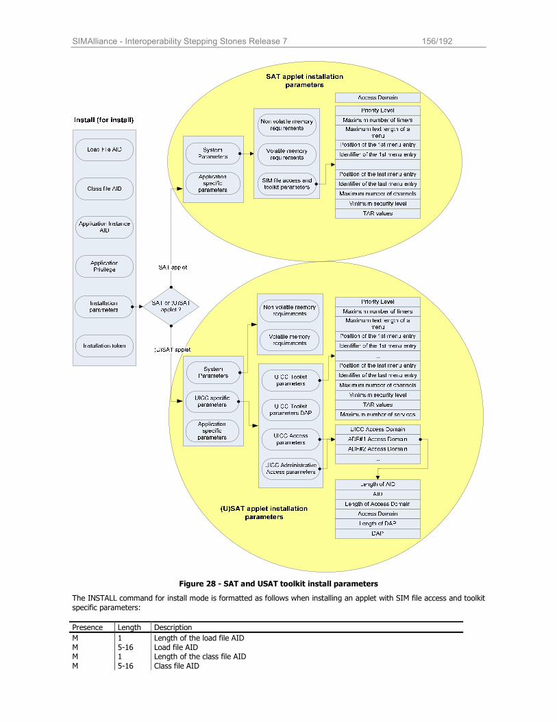
SIMAlliance - Interoperability Stepping Stones Release 7 156/192
Figure 28 - SAT and USAT toolkit install parameters
The INSTALL command for install mode is formatted as follows when installing an applet with SIM file access and toolkit
specific parameters:
Presence Length Description
M 1 Length of the load file AID M 5-16 Load file AID M 1 Length of the class file AID
M 5-16 Class file AID
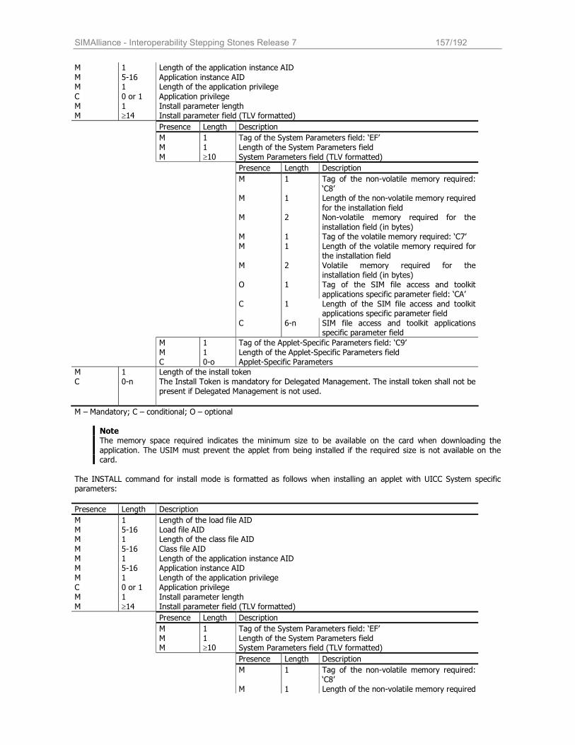
SIMAlliance - Interoperability Stepping Stones Release 7 157/192
M 1 Length of the application instance AID
M 5-16 Application instance AID M 1 Length of the application privilege
C 0 or 1 Application privilege M 1 Install parameter length M ≥14 Install parameter field (TLV formatted)
Presence Length Description
M 1 Tag of the System Parameters field: ‘EF’ M 1 Length of the System Parameters field
M ≥10 System Parameters field (TLV formatted)
Presence Length Description
M 1 Tag of the non-volatile memory required:
‘C8’ M 1 Length of the non-volatile memory required
for the installation field M 2 Non-volatile memory required for the
installation field (in bytes) M 1 Tag of the volatile memory required: ‘C7’ M 1 Length of the volatile memory required for
the installation field M 2 Volatile memory required for the
installation field (in bytes) O 1 Tag of the SIM file access and toolkit
applications specific parameter field: ‘CA’
C 1 Length of the SIM file access and toolkit applications specific parameter field
C 6-n SIM file access and toolkit applications specific parameter field
M 1 Tag of the Applet-Specific Parameters field: ‘C9’ M 1 Length of the Applet-Specific Parameters field C 0-o Applet-Specific Parameters
M 1 Length of the install token C 0-n The Install Token is mandatory for Delegated Management. The install token shall not be
present if Delegated Management is not used.
M – Mandatory; C – conditional; O – optional
Note The memory space required indicates the minimum size to be available on the card when downloading the
application. The USIM must prevent the applet from being installed if the required size is not available on the card.
The INSTALL command for install mode is formatted as follows when installing an applet with UICC System specific parameters:
Presence Length Description
M 1 Length of the load file AID M 5-16 Load file AID M 1 Length of the class file AID
M 5-16 Class file AID M 1 Length of the application instance AID M 5-16 Application instance AID M 1 Length of the application privilege C 0 or 1 Application privilege M 1 Install parameter length M ≥14 Install parameter field (TLV formatted)
Presence Length Description
M 1 Tag of the System Parameters field: ‘EF’ M 1 Length of the System Parameters field M ≥10 System Parameters field (TLV formatted)
Presence Length Description
M 1 Tag of the non-volatile memory required: ‘C8’
M 1 Length of the non-volatile memory required
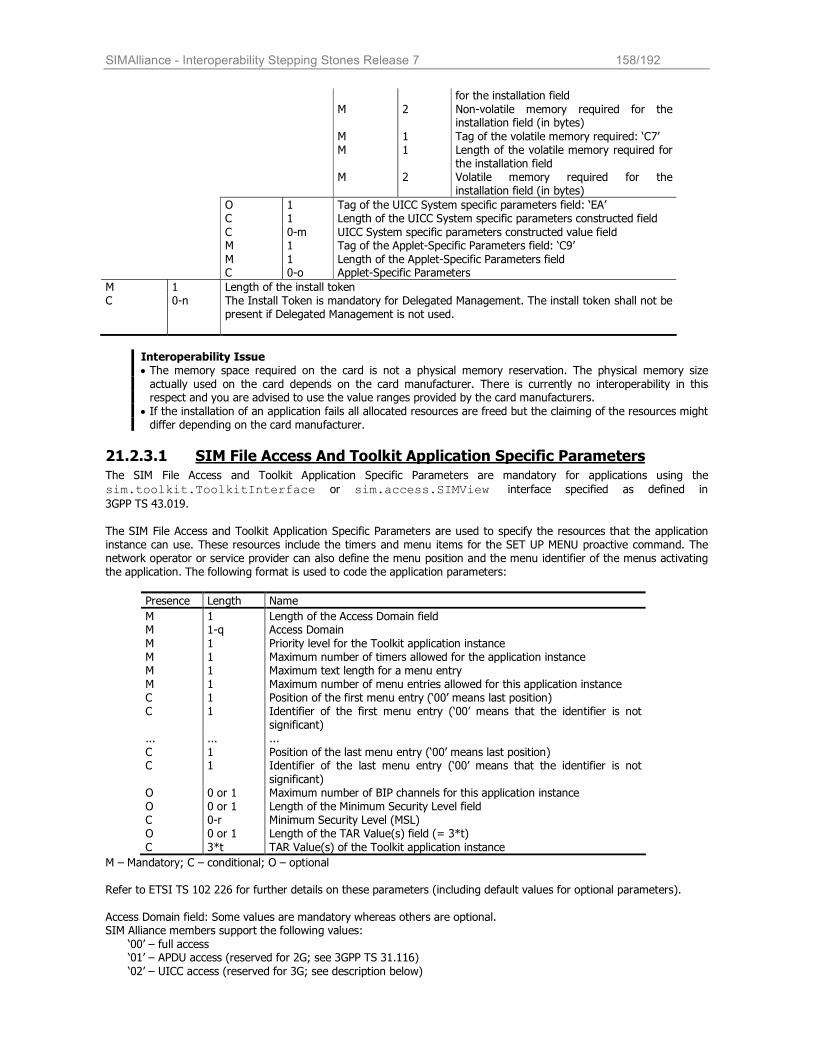
SIMAlliance - Interoperability Stepping Stones Release 7 158/192
for the installation field
M 2 Non-volatile memory required for the installation field (in bytes)
M 1 Tag of the volatile memory required: ‘C7’ M 1 Length of the volatile memory required for
the installation field M 2 Volatile memory required for the
installation field (in bytes)
O 1 Tag of the UICC System specific parameters field: ‘EA’ C 1 Length of the UICC System specific parameters constructed field
C 0-m UICC System specific parameters constructed value field M 1 Tag of the Applet-Specific Parameters field: ‘C9’
M 1 Length of the Applet-Specific Parameters field C 0-o Applet-Specific Parameters
M 1 Length of the install token C 0-n The Install Token is mandatory for Delegated Management. The install token shall not be
present if Delegated Management is not used.
Interoperability Issue • The memory space required on the card is not a physical memory reservation. The physical memory size actually used on the card depends on the card manufacturer. There is currently no interoperability in this respect and you are advised to use the value ranges provided by the card manufacturers.
• If the installation of an application fails all allocated resources are freed but the claiming of the resources might differ depending on the card manufacturer.
21.2.3.1 SIM File Access And Toolkit Application Specific Parameters The SIM File Access and Toolkit Application Specific Parameters are mandatory for applications using the
sim.toolkit.ToolkitInterface or sim.access.SIMView interface specified as defined in
3GPP TS 43.019.
The SIM File Access and Toolkit Application Specific Parameters are used to specify the resources that the application instance can use. These resources include the timers and menu items for the SET UP MENU proactive command. The network operator or service provider can also define the menu position and the menu identifier of the menus activating the application. The following format is used to code the application parameters:
Presence Length Name
M 1 Length of the Access Domain field M 1-q Access Domain
M 1 Priority level for the Toolkit application instance M 1 Maximum number of timers allowed for the application instance M 1 Maximum text length for a menu entry M 1 Maximum number of menu entries allowed for this application instance C 1 Position of the first menu entry (‘00’ means last position) C 1 Identifier of the first menu entry (‘00’ means that the identifier is not
significant) ... ... ...
C 1 Position of the last menu entry (‘00’ means last position) C 1 Identifier of the last menu entry (‘00’ means that the identifier is not
significant) O 0 or 1 Maximum number of BIP channels for this application instance O 0 or 1 Length of the Minimum Security Level field C 0-r Minimum Security Level (MSL) O 0 or 1 Length of the TAR Value(s) field (= 3*t)
C 3*t TAR Value(s) of the Toolkit application instance
M – Mandatory; C – conditional; O – optional Refer to ETSI TS 102 226 for further details on these parameters (including default values for optional parameters).
Access Domain field: Some values are mandatory whereas others are optional. SIM Alliance members support the following values:
‘00’ – full access ‘01’ – APDU access (reserved for 2G; see 3GPP TS 31.116)
‘02’ – UICC access (reserved for 3G; see description below)
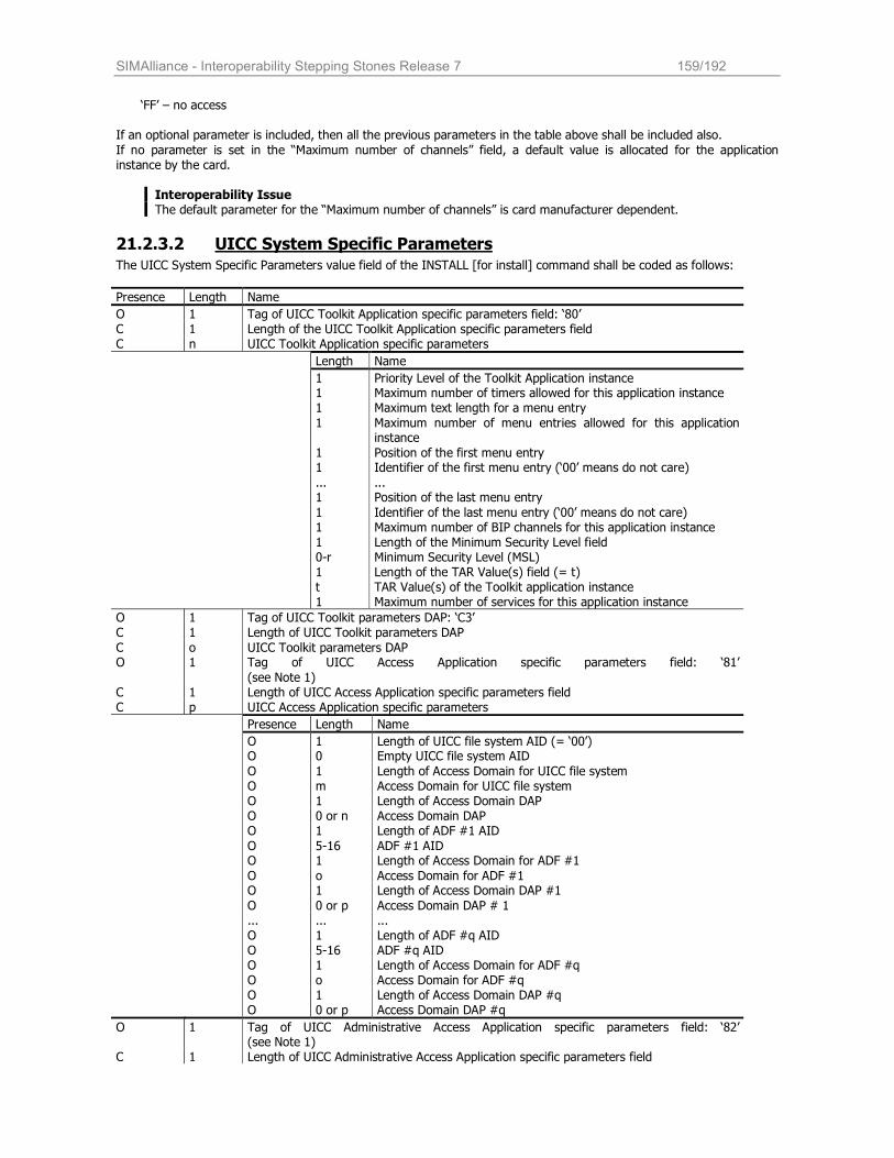
SIMAlliance - Interoperability Stepping Stones Release 7 159/192
‘FF’ – no access
If an optional parameter is included, then all the previous parameters in the table above shall be included also.
If no parameter is set in the “Maximum number of channels” field, a default value is allocated for the application instance by the card.
Interoperability Issue The default parameter for the “Maximum number of channels” is card manufacturer dependent.
21.2.3.2 UICC System Specific Parameters The UICC System Specific Parameters value field of the INSTALL [for install] command shall be coded as follows:
Presence Length Name
O 1 Tag of UICC Toolkit Application specific parameters field: ‘80’ C 1 Length of the UICC Toolkit Application specific parameters field C n UICC Toolkit Application specific parameters
Length Name
1 Priority Level of the Toolkit Application instance 1 Maximum number of timers allowed for this application instance 1 Maximum text length for a menu entry
1 Maximum number of menu entries allowed for this application instance
1 Position of the first menu entry 1 Identifier of the first menu entry (‘00’ means do not care)
... ... 1 Position of the last menu entry
1 Identifier of the last menu entry (‘00’ means do not care) 1 Maximum number of BIP channels for this application instance 1 Length of the Minimum Security Level field 0-r Minimum Security Level (MSL) 1 Length of the TAR Value(s) field (= t) t TAR Value(s) of the Toolkit application instance 1 Maximum number of services for this application instance
O 1 Tag of UICC Toolkit parameters DAP: ‘C3’ C 1 Length of UICC Toolkit parameters DAP
C o UICC Toolkit parameters DAP O 1 Tag of UICC Access Application specific parameters field: ‘81’
(see Note 1) C 1 Length of UICC Access Application specific parameters field C p UICC Access Application specific parameters
Presence Length Name
O 1 Length of UICC file system AID (= ‘00’) O 0 Empty UICC file system AID
O 1 Length of Access Domain for UICC file system O m Access Domain for UICC file system O 1 Length of Access Domain DAP O 0 or n Access Domain DAP O 1 Length of ADF #1 AID
O 5-16 ADF #1 AID O 1 Length of Access Domain for ADF #1
O o Access Domain for ADF #1 O 1 Length of Access Domain DAP #1
O 0 or p Access Domain DAP # 1 ... ... ... O 1 Length of ADF #q AID O 5-16 ADF #q AID O 1 Length of Access Domain for ADF #q O o Access Domain for ADF #q O 1 Length of Access Domain DAP #q O 0 or p Access Domain DAP #q
O 1 Tag of UICC Administrative Access Application specific parameters field: ‘82’ (see Note 1)
C 1 Length of UICC Administrative Access Application specific parameters field
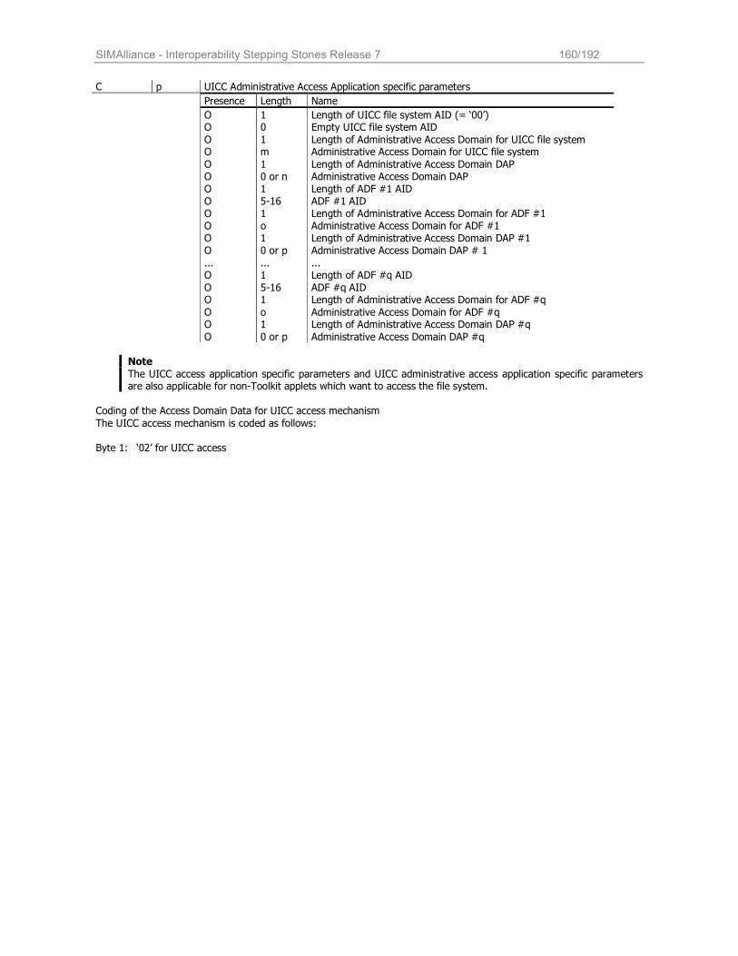
SIMAlliance - Interoperability Stepping Stones Release 7 160/192
C p UICC Administrative Access Application specific parameters
Presence Length Name
O 1 Length of UICC file system AID (= ‘00’) O 0 Empty UICC file system AID
O 1 Length of Administrative Access Domain for UICC file system O m Administrative Access Domain for UICC file system
O 1 Length of Administrative Access Domain DAP O 0 or n Administrative Access Domain DAP O 1 Length of ADF #1 AID O 5-16 ADF #1 AID O 1 Length of Administrative Access Domain for ADF #1 O o Administrative Access Domain for ADF #1 O 1 Length of Administrative Access Domain DAP #1 O 0 or p Administrative Access Domain DAP # 1
... ... ... O 1 Length of ADF #q AID
O 5-16 ADF #q AID O 1 Length of Administrative Access Domain for ADF #q
O o Administrative Access Domain for ADF #q O 1 Length of Administrative Access Domain DAP #q
O 0 or p Administrative Access Domain DAP #q
Note
The UICC access application specific parameters and UICC administrative access application specific parameters are also applicable for non-Toolkit applets which want to access the file system.
Coding of the Access Domain Data for UICC access mechanism
The UICC access mechanism is coded as follows: Byte 1: ‘02’ for UICC access
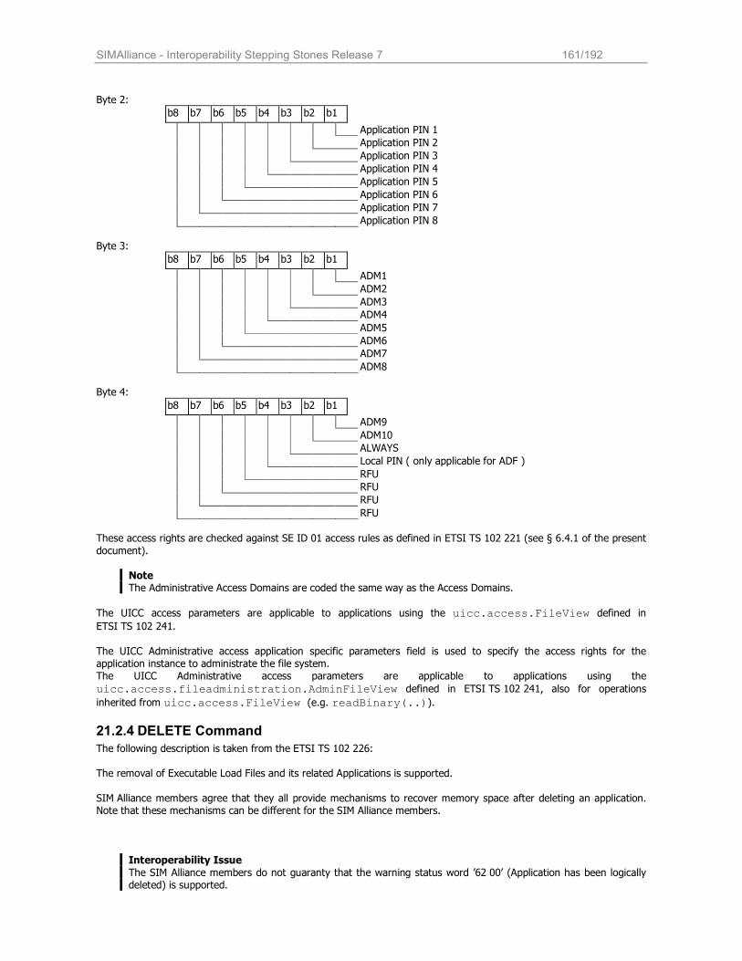
SIMAlliance - Interoperability Stepping Stones Release 7 161/192
Byte 2:
b8 b7 b6 b5 b4 b3 b2 b1
Application PIN 1
Application PIN 2
Application PIN 3
Application PIN 4
Application PIN 5
Application PIN 6
Application PIN 7
Application PIN 8
Byte 3:
b8 b7 b6 b5 b4 b3 b2 b1
ADM1
ADM2
ADM3
ADM4
ADM5
ADM6
ADM7
ADM8
Byte 4:
b8 b7 b6 b5 b4 b3 b2 b1
ADM9
ADM10
ALWAYS
Local PIN ( only applicable for ADF )
RFU
RFU
RFU
RFU
These access rights are checked against SE ID 01 access rules as defined in ETSI TS 102 221 (see § 6.4.1 of the present
document).
Note The Administrative Access Domains are coded the same way as the Access Domains.
The UICC access parameters are applicable to applications using the uicc.access.FileView defined in ETSI TS 102 241.
The UICC Administrative access application specific parameters field is used to specify the access rights for the application instance to administrate the file system. The UICC Administrative access parameters are applicable to applications using the
uicc.access.fileadministration.AdminFileView defined in ETSI TS 102 241, also for operations
inherited from uicc.access.FileView (e.g. readBinary(..)).
21.2.4 DELETE Command
The following description is taken from the ETSI TS 102 226:
The removal of Executable Load Files and its related Applications is supported.
SIM Alliance members agree that they all provide mechanisms to recover memory space after deleting an application. Note that these mechanisms can be different for the SIM Alliance members.
Interoperability Issue
The SIM Alliance members do not guaranty that the warning status word ’62 00’ (Application has been logically deleted) is supported.
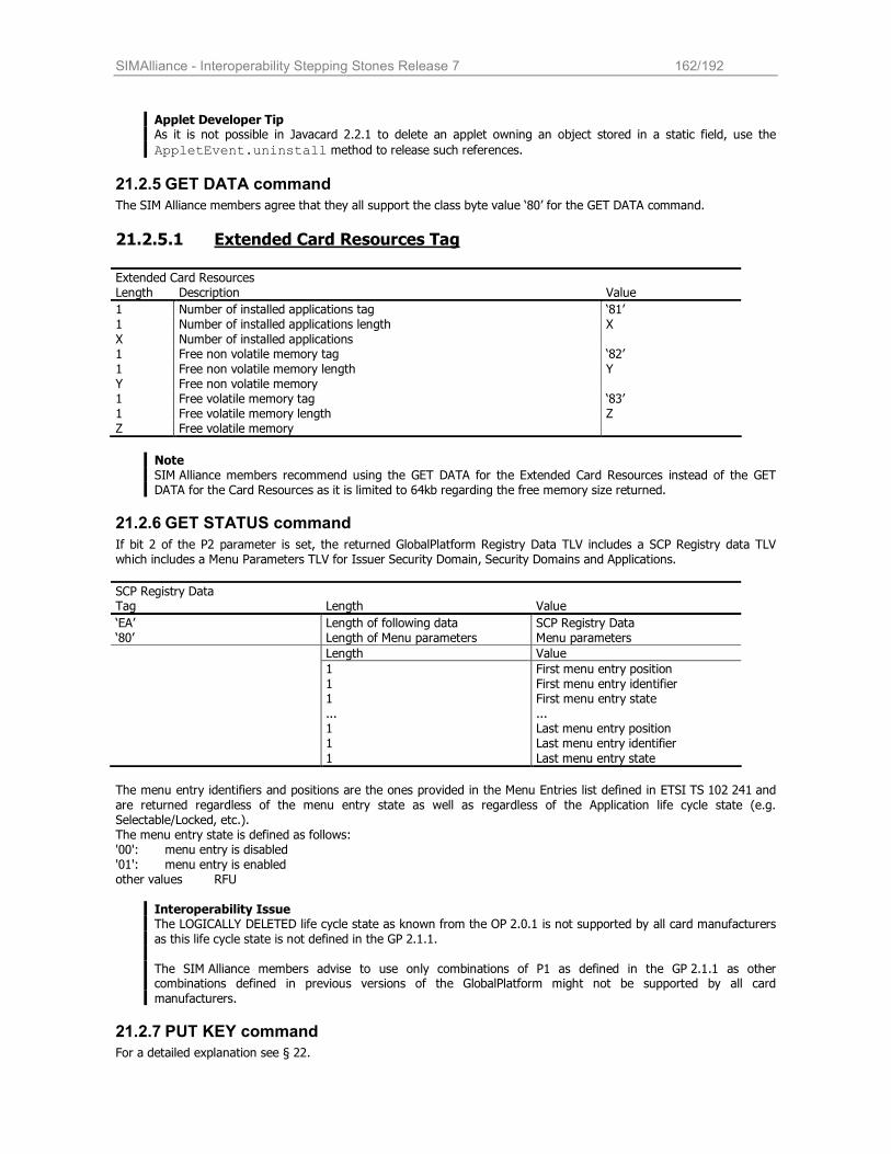
SIMAlliance - Interoperability Stepping Stones Release 7 162/192
Applet Developer Tip As it is not possible in Javacard 2.2.1 to delete an applet owning an object stored in a static field, use the
AppletEvent.uninstall method to release such references.
21.2.5 GET DATA command
The SIM Alliance members agree that they all support the class byte value ‘80’ for the GET DATA command.
21.2.5.1 Extended Card Resources Tag
Extended Card Resources Length Description Value
1 Number of installed applications tag ‘81’ 1 Number of installed applications length X
X Number of installed applications 1 Free non volatile memory tag ‘82’
1 Free non volatile memory length Y Y Free non volatile memory 1 Free volatile memory tag ‘83’ 1 Free volatile memory length Z Z Free volatile memory
Note SIM Alliance members recommend using the GET DATA for the Extended Card Resources instead of the GET DATA for the Card Resources as it is limited to 64kb regarding the free memory size returned.
21.2.6 GET STATUS command
If bit 2 of the P2 parameter is set, the returned GlobalPlatform Registry Data TLV includes a SCP Registry data TLV which includes a Menu Parameters TLV for Issuer Security Domain, Security Domains and Applications.
SCP Registry Data Tag Length Value
‘EA’ Length of following data SCP Registry Data ‘80’ Length of Menu parameters Menu parameters
Length Value
1 First menu entry position 1 First menu entry identifier 1 First menu entry state ... ... 1 Last menu entry position 1 Last menu entry identifier
1 Last menu entry state
The menu entry identifiers and positions are the ones provided in the Menu Entries list defined in ETSI TS 102 241 and
are returned regardless of the menu entry state as well as regardless of the Application life cycle state (e.g. Selectable/Locked, etc.). The menu entry state is defined as follows: '00': menu entry is disabled '01': menu entry is enabled other values RFU
Interoperability Issue The LOGICALLY DELETED life cycle state as known from the OP 2.0.1 is not supported by all card manufacturers
as this life cycle state is not defined in the GP 2.1.1.
The SIM Alliance members advise to use only combinations of P1 as defined in the GP 2.1.1 as other combinations defined in previous versions of the GlobalPlatform might not be supported by all card
manufacturers.
21.2.7 PUT KEY command
For a detailed explanation see § 22.
SIMAlliance - Interoperability Stepping Stones Release 7 163/192
22 Security domain and Key Management
22.1 Security Domains on UICC Java Cards
22.1.1 Introduction
The GP security architecture introduces the role of the card issuer and the application provider. It further defines four specific on-card entities: the Card Manager, the Card Runtime Environment, Applications, and Security Domains. The Issuer Security Domain and the Global Platform Environment (OPEN) are always created by the Card Issuer, but
applications may also be created by application providers. To ensure a secure way of communication between on-card applications and off-card entities, keys are needed to encrypt / decrypt messages and calculate checksums. Physically, a SD is a special application that supports a secure communication between an Application Provider’s application and off-card entities during its personalization phase and runtime. For this purpose, a SD manages its own
keys. It is desirable to limit the access to such keys, so that not every application provider knows the Card Issuer’s keys, and a
Card Issuer knows not the keys of any application provider. To grant such an access control, GP introduces the concept of Security Domains (SD): every application is associated with a SD, there is a default SD on each card, the Issuer
Security Domain. All applications of provider A can be associated with A’s SD, all applications of provider B with B’s SD etc.
GP defines additional privileges for Security Domains such as DAP verification, Delegated Management, the mutual authentication process, the secure channel management and an API to manage the access of applications to a SD. Parts of this functionality may be covered in future ETSI specifications and will then be introduced in this document.
22.1.2 Security Domains in non-OTA communication
In non-OTA communication, a security domain may provide means of establishing a secure channel between the application and the outside world, as shown in the picture below. At minimum, the security domain has to provide access
to keys that can be utilized by applications for cryptographic purposes. Access to keys and secure channels is granted via methods in the GP API. Refer to GP card implementation specification for more details on security in non-OTA communication. This topic is only
covered here for reasons of understandability. It depends on the card manufacturer to which extend the non-OTA part of GP is implemented.
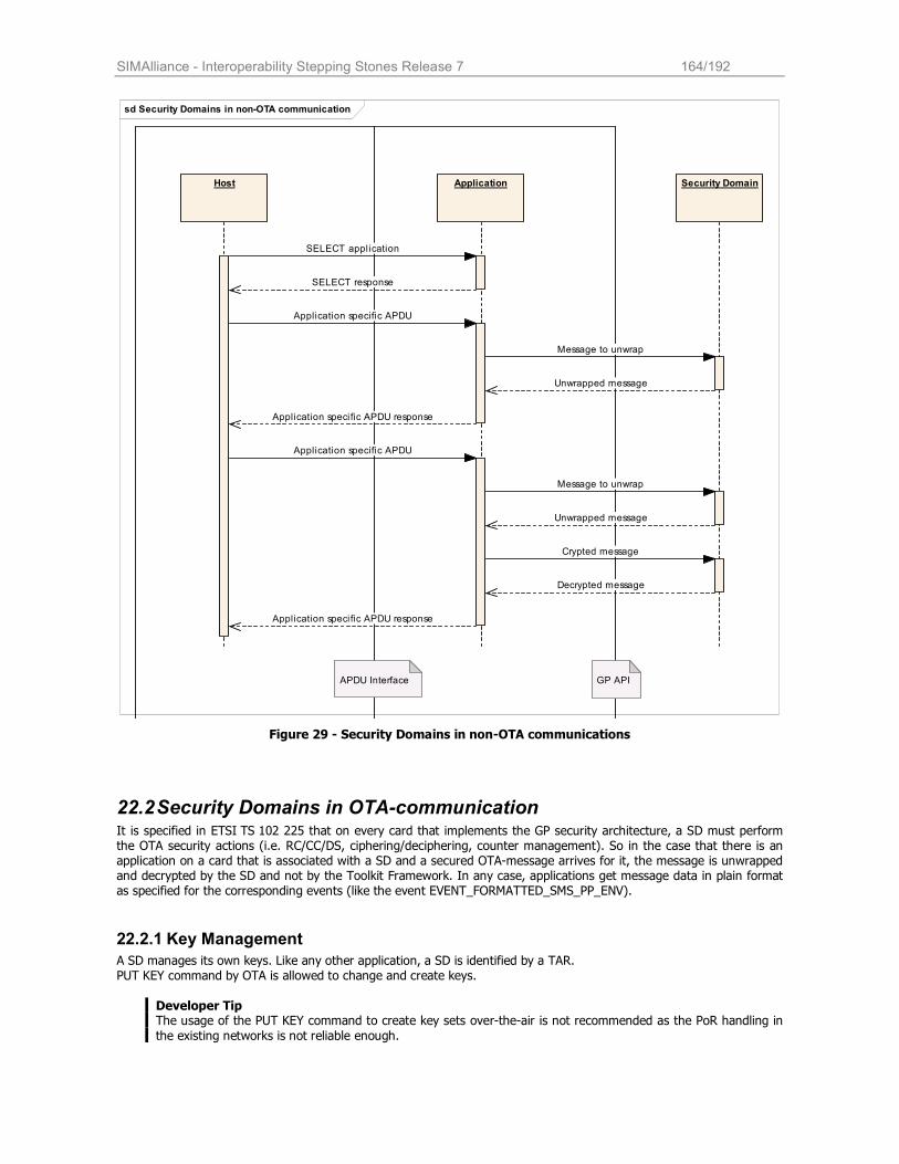
SIMAlliance - Interoperability Stepping Stones Release 7 164/192
sd Security Domains in non-OTA communication
Host Application Security Domain
APDU Interface GP API
SELECT application
SELECT response
Application specific APDU
Message to unwrap
Unwrapped message
Application specific APDU response
Application specific APDU
Message to unwrap
Unwrapped message
Crypted message
Decrypted message
Application specific APDU response
Figure 29 - Security Domains in non-OTA communications
22.2 Security Domains in OTA-communication It is specified in ETSI TS 102 225 that on every card that implements the GP security architecture, a SD must perform the OTA security actions (i.e. RC/CC/DS, ciphering/deciphering, counter management). So in the case that there is an application on a card that is associated with a SD and a secured OTA-message arrives for it, the message is unwrapped and decrypted by the SD and not by the Toolkit Framework. In any case, applications get message data in plain format as specified for the corresponding events (like the event EVENT_FORMATTED_SMS_PP_ENV).
22.2.1 Key Management
A SD manages its own keys. Like any other application, a SD is identified by a TAR. PUT KEY command by OTA is allowed to change and create keys.
Developer Tip The usage of the PUT KEY command to create key sets over-the-air is not recommended as the PoR handling in
the existing networks is not reliable enough.
SIMAlliance - Interoperability Stepping Stones Release 7 165/192
The PUT KEY is either issued via a secure channel or via OTA, in the latter case the TAR is evaluated by the Toolkit
Framework to channel the command to the right Security Domain. According to the GP specification, keys have to be associated with a certain algorithm and length. In the PUT KEY
command, an algorithm identifier together with length information is sent to the card together with the key data. Keys can be updated by using the PUT KEY command, but the key deletion command may not be supported by each card. Keys are always organized in Key Sets. According to GP, a Key Set may contain one to many keys. The ETSI TS 102 225 precises the definition to three keys per key sets (KID, KIc and DEK see also § Error! Reference
source not found.) and an additional counter. A maximum of 15 key sets for OTA transportation is allowed for the ISD. SIM Alliance members support up to 15 key
sets for OTA transportation for each security domain. Key Sets are identified with a version number that is unique within its SD. Keys within key sets are identified by a unique
index within the key set. Key Set versions and key indices have to be specified in the PUT KEY command. The key used for ciphering the key values (e.g. KIc, KID or DEK) of the PUT KEY command is the key with identifier 3 (i.e. DEK). It is a static key. When replacing or adding key(s) within the same key set, or when updating the key version number of a key set, the encrypting key to be used is the DEK of the same key version number as the changed key(s). When creating key set(s), the encrypting key to be used is the DEK of the same key version number as KIc and KID in the Command Packet containing the PUT KEY command. The key version number of KIc and KID used to secure the Response Packet is the same as the key version number indicated in the Command Packet.
The transport security keys (i.e. KIc/KID) used to secure the Response Packet are the same as the ones of the Command Packet containing the PUT KEY command.
22.2.2 Set Up of Security Domains
The implementation and installation of a SD depends very much on the card implementation and is proprietary for each
manufacturer.
22.2.3 Interoperability regarding Security Domains and GP security
In summary, the following points apply for the interoperability of Security Domains on UICC Java Cards:
SIM Alliance members are interoperable: All SIM Alliance members support Security Domains (other than the Issuer Security Domain) for OTA
The addressed application gets the message in plain format. All SIM Alliance members support key management as specified is above.
All applications must be associated with the ISD or with one other security domain. For applications associated with an SD, the keys of the SD are taken for OTA security.
Interoperability Issue The interface between Card Manager and Security Domains is open. The way to implement security in a SD is not standardized. The implementation is proprietary and as a consequence it is not possible to load and install Security Domains in an interoperable way.
22.3 Key Management
22.3.1 Algorithm
The algorithm to be used depends on the DES algorithm specified as DEA in ISO 8731-1. The algorithm to be used is defined as follows:
• DES in CBC mode is described in ISO/IEC 10116 • Triple DES in outer-CBC mode is described in "Applied Cryptography: Protocols, Algorithms, and Source Code in
C, 2nd Edition" • DES in ECB mode is described in ISO/IEC 10116
The initial chaining value for CBC modes is zero. SIM Alliance members support DES and triple DES in CBC/ECB mode for ciphering and in CBC mode for cryptographic
checksum. The length of the keys to be used depends on the algorithm used. If a DES in CBC or ECB mode is used, the key should have a length of eight bytes. To ensure interoperability, you are advised to use a:
16-byte key divided into two keys of eight bytes if triple DES using two different keys is used
24-byte key divided into three keys of eight bytes if triple DES using three different keys is used

SIMAlliance - Interoperability Stepping Stones Release 7 166/192
22.3.2 Key Set Version
The key set version to be used in the KIc and KID bytes refers to a Global Platform key set version number. The key set version 0 is reserved. Therefore the key set version is then between ‘01’ and ‘0F’. The key set version ‘11’ is used for UICC Toolkit Parameters DAP and Access Domain DAP verification. The number of key sets, as well as the number of security domains, may be defined at the personalization step, according to operators’
requirements.

SIMAlliance - Interoperability Stepping Stones Release 7 167/192
A AID and TARs (annex)
Each package, applet, and instance of an applet loaded on a Java card must be assigned a unique identifier, known as
an application identifier (AID). An AID is a string of between 5 and 16 hexadecimal bytes. The first five bytes of an AID (the RID) uniquely identify the applet provider, that is, the company supplying the package or applet. An applet provider must apply for a registered RID from ISO; examples for RID could be found in chapter § A.2. The remaining bytes (up to 11) of an AID contain the Proprietary Identifier eXtension (PIX). The PIX uniquely identifies a package, applet, or applet instance. The PIX is assigned by the applet provider. The TAR (Toolkit Application Reference) is a 3-byte code used to uniquely identify a second level application (e.g. Toolkit
Application). It is used when targeting an applet instance with an OTA message. Prior to the standard specification Release 6, an applet instance could have only one TAR; the value of which is defined by the 13th, 14th and 15th byte of the AID. The standard specification Release 6 allows you to define a list of TARs that are associated with an applet instance. The TAR list is defined when installing the applet instance; if the TAR list is not defined, then the 13th, 14th and 15th byte of the AID are used as the unique TAR of the instance. If the TAR of an applet is not defined (no TAR list defined and the length of the applet instance’s AID is less than 15 bytes), the applet cannot be triggered by OTA.
Developer Tip
The SIM Alliance members suggests to not define a TAR value (TAR length of less than 15 bytes or no TAR list) if it is not functionally required by the application (e.g. no OTA triggering).
A.1 AID Format This section provides a basic description of the AID data format used in Java Card technology. For full details, refer to ISO 7816-5, AID Registration Category 'D' Format.
The AID format used by the Java Card platform is an array of bytes that can be interpreted as two distinct parts, as shown in Figure 1. The first part is a five-byte value known as a RID (Registered application provider identifier). The second part is a variable length value known as PIX (proprietary identifier extension). PIX may have a length between 0 and 11 bytes. Therefore, an AID may have a total length between 5 and 16 bytes.
<--------------------------- Application IDentifier (AID) ----------------------------->
Registered application provider IDentifier (RID)
Proprietary application Identifier eXtension (PIX)
<--------------- 5 bytes ----------------> <--------------- 0 - 11 bytes -------------->
ISO controls the assignment of RIDs to companies, with each company obtaining its own unique RID. Companies assign PIXs for AIDs using their own RIDs.
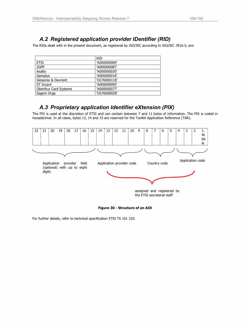
SIMAlliance - Interoperability Stepping Stones Release 7 168/192
A.2 Registered application provider IDentifier (RID) The RIDs dealt with in the present document, as registered by ISO/IEC according to ISO/IEC 7816-5, are:
RID
ETSI 'A000000009'
3GPP 'A000000087'
Axalto ‘A000000030’
Gemplus ‘A000000018’
Giesecke & Devrient ‘D276000118’
ST Incard ‘A000000095’
Oberthur Card Systems ‘A000000077’
Sagem Orga ‘D276000028’
A.3 Proprietary application Identifier eXtension (PIX) The PIX is used at the discretion of ETSI and can contain between 7 and 11 bytes of information. The PIX is coded in hexadecimal. In all cases, bytes 13, 14 and 15 are reserved for the Toolkit Application Reference (TAR).
22 21 20 19 18 17 16 15 14 13 12 11 10 9 8 7 6 5 4 3 2 1. Ni
bble
Figure 30 - Structure of an AID
For further details, refer to technical specification ETSI TS 101 220.
assigned and registered by
the ETSI secretarial staff
Application code Country code Application provider code Application provider field
(optional) with up to eight digits
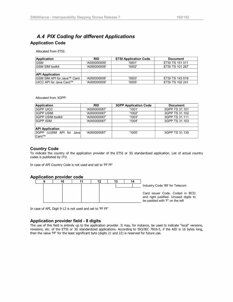
SIMAlliance - Interoperability Stepping Stones Release 7 169/192
A.4 PIX Coding for different Applications
Application Code
Allocated from ETSI:
Application RID ETSI Application Code Document
GSM 'A000000009' '0001' ETSI TS 151 011
GSM SIM toolkit 'A000000009' '0002' ETSI TS 101 267
API Application
GSM SIM API for Java™ Card 'A000000009' '0003' ETSI TS 143 019
UICC API for Java Card™ 'A000000009' '0005' ETSI TS 102 241
Allocated from 3GPP:
Application RID 3GPP Application Code Document
3GPP UICC 'A000000087' '1001' 3GPP TS 31.101
3GPP USIM 'A000000087' '1002' 3GPP TS 31.102
3GPP USIM toolkit 'A000000087' '1003' 3GPP TS 31.111
3GPP ISIM 'A000000087' '1004' 3GPP TS 31.103
API Application
3GPP (U)SIM API for Java Card™
'A000000087' '1005' 3GPP TS 31.130
Country Code To indicate the country of the application provider of the ETSI or 3G standardized application. List of actual country codes is published by ITU. In case of API Country Code is not used and set to ‘FF FF’
Application provider code 9 10 11 12 13 14
Industry Code '89' for Telecom
Card issuer Code. Coded in BCD and right justified. Unused digits to be padded with 'F' on the left
In case of API, Digit 9-12 is not used and set to ‘FF FF’
Application provider field - 8 digits The use of this field is entirely up to the application provider. It may, for instance, be used to indicate "local" versions, revisions, etc. of the ETSI or 3G standardized applications. According to ISO/IEC 7816-5, if the AID is 16 bytes long, then the value 'FF' for the least significant byte (digits 21 and 22) is reserved for future use.
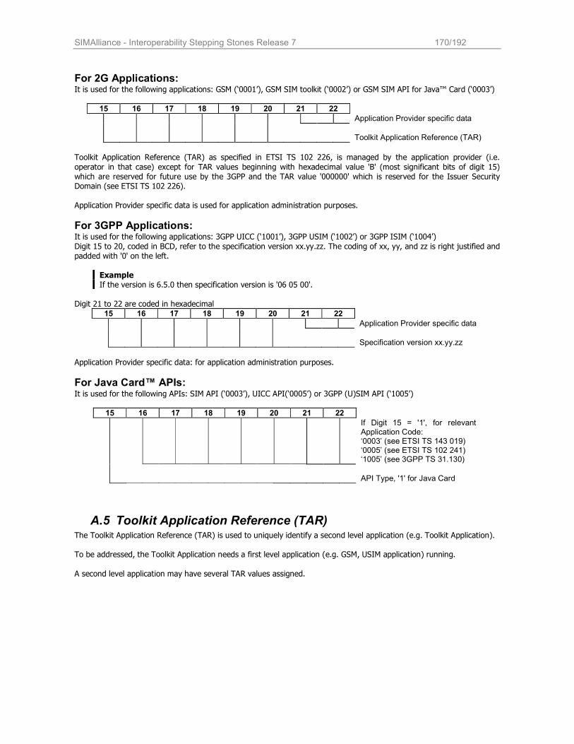
SIMAlliance - Interoperability Stepping Stones Release 7 170/192
For 2G Applications: It is used for the following applications: GSM (‘0001’), GSM SIM toolkit (‘0002’) or GSM SIM API for Java™ Card (‘0003’)
15 16 17 18 19 20 21 22
Application Provider specific data
Toolkit Application Reference (TAR)
Toolkit Application Reference (TAR) as specified in ETSI TS 102 226, is managed by the application provider (i.e.
operator in that case) except for TAR values beginning with hexadecimal value 'B' (most significant bits of digit 15) which are reserved for future use by the 3GPP and the TAR value '000000' which is reserved for the Issuer Security Domain (see ETSI TS 102 226).
Application Provider specific data is used for application administration purposes.
For 3GPP Applications: It is used for the following applications: 3GPP UICC (‘1001’), 3GPP USIM (‘1002’) or 3GPP ISIM (‘1004’)
Digit 15 to 20, coded in BCD, refer to the specification version xx.yy.zz. The coding of xx, yy, and zz is right justified and padded with '0' on the left.
Example If the version is 6.5.0 then specification version is '06 05 00'.
Digit 21 to 22 are coded in hexadecimal
15 16 17 18 19 20 21 22
Application Provider specific data
Specification version xx.yy.zz
Application Provider specific data: for application administration purposes.
For Java Card™ APIs: It is used for the following APIs: SIM API (‘0003’), UICC API(‘0005’) or 3GPP (U)SIM API (‘1005’)
15 16 17 18 19 20 21 22
If Digit 15 = '1', for relevant Application Code: ‘0003’ (see ETSI TS 143 019) ‘0005’ (see ETSI TS 102 241) ‘1005’ (see 3GPP TS 31.130)
API Type, '1' for Java Card
A.5 Toolkit Application Reference (TAR) The Toolkit Application Reference (TAR) is used to uniquely identify a second level application (e.g. Toolkit Application).
To be addressed, the Toolkit Application needs a first level application (e.g. GSM, USIM application) running.
A second level application may have several TAR values assigned.
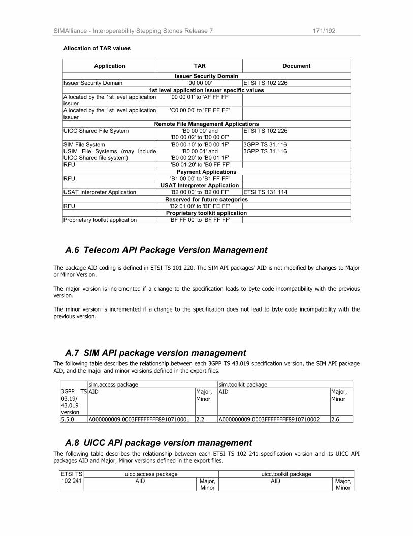
SIMAlliance - Interoperability Stepping Stones Release 7 171/192
Allocation of TAR values
Application TAR Document
Issuer Security Domain
Issuer Security Domain '00 00 00' ETSI TS 102 226
1st level application issuer specific values
Allocated by the 1st level application issuer
'00 00 01' to 'AF FF FF'
Allocated by the 1st level application issuer
'C0 00 00' to 'FF FF FF'
Remote File Management Applications
UICC Shared File System 'B0 00 00' and 'B0 00 02' to 'B0 00 0F'
ETSI TS 102 226
SIM File System 'B0 00 10' to 'B0 00 1F' 3GPP TS 31.116
USIM File Systems (may include UICC Shared file system)
'B0 00 01' and 'B0 00 20' to 'B0 01 1F'
3GPP TS 31.116
RFU 'B0 01 20' to 'B0 FF FF'
Payment Applications
RFU 'B1 00 00' to 'B1 FF FF'
USAT Interpreter Application
USAT Interpreter Application 'B2 00 00' to 'B2 00 FF' ETSI TS 131 114
Reserved for future categories
RFU 'B2 01 00' to 'BF FE FF'
Proprietary toolkit application
Proprietary toolkit application 'BF FF 00' to 'BF FF FF'
A.6 Telecom API Package Version Management The package AID coding is defined in ETSI TS 101 220. The SIM API packages' AID is not modified by changes to Major or Minor Version.
The major version is incremented if a change to the specification leads to byte code incompatibility with the previous version.
The minor version is incremented if a change to the specification does not lead to byte code incompatibility with the
previous version.
A.7 SIM API package version management The following table describes the relationship between each 3GPP TS 43.019 specification version, the SIM API package AID, and the major and minor versions defined in the export files.
sim.access package sim.toolkit package 3GPP TS 03.19/ 43.019 version
AID Major,
Minor
AID Major,
Minor
5.5.0 A000000009 0003FFFFFFFF8910710001 2.2 A000000009 0003FFFFFFFF8910710002 2.6
A.8 UICC API package version management The following table describes the relationship between each ETSI TS 102 241 specification version and its UICC API
packages AID and Major, Minor versions defined in the export files.
uicc.access package uicc.toolkit package ETSI TS 102 241 AID Major,
Minor AID Major,
Minor
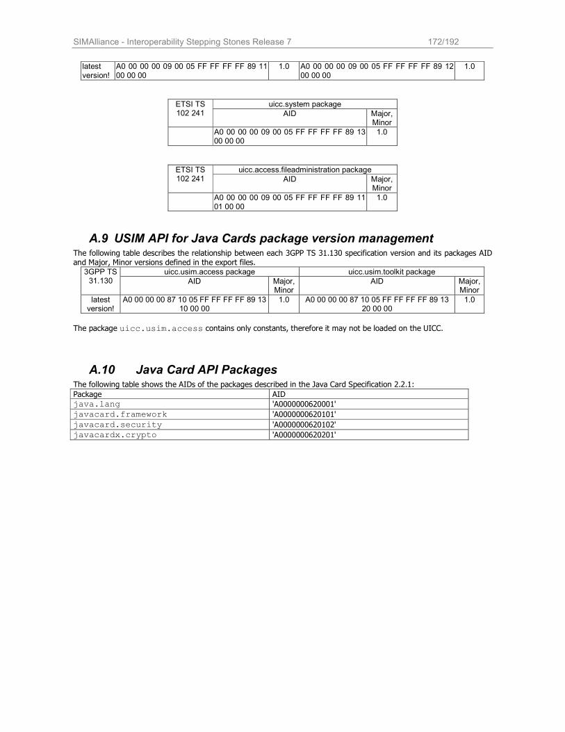
SIMAlliance - Interoperability Stepping Stones Release 7 172/192
latest version!
A0 00 00 00 09 00 05 FF FF FF FF 89 11 00 00 00
1.0 A0 00 00 00 09 00 05 FF FF FF FF 89 12 00 00 00
1.0
uicc.system package ETSI TS
102 241 AID Major, Minor
A0 00 00 00 09 00 05 FF FF FF FF 89 13 00 00 00
1.0
uicc.access.fileadministration package ETSI TS 102 241 AID Major,
Minor
A0 00 00 00 09 00 05 FF FF FF FF 89 11 01 00 00
1.0
A.9 USIM API for Java Cards package version management The following table describes the relationship between each 3GPP TS 31.130 specification version and its packages AID and Major, Minor versions defined in the export files.
uicc.usim.access package uicc.usim.toolkit package 3GPP TS 31.130 AID Major,
Minor AID Major,
Minor
latest version!
A0 00 00 00 87 10 05 FF FF FF FF 89 13 10 00 00
1.0 A0 00 00 00 87 10 05 FF FF FF FF 89 13 20 00 00
1.0
The package uicc.usim.access contains only constants, therefore it may not be loaded on the UICC.
A.10 Java Card API Packages The following table shows the AIDs of the packages described in the Java Card Specification 2.2.1:
Package AID
java.lang 'A0000000620001'
javacard.framework 'A0000000620101'
javacard.security 'A0000000620102'
javacardx.crypto 'A0000000620201'
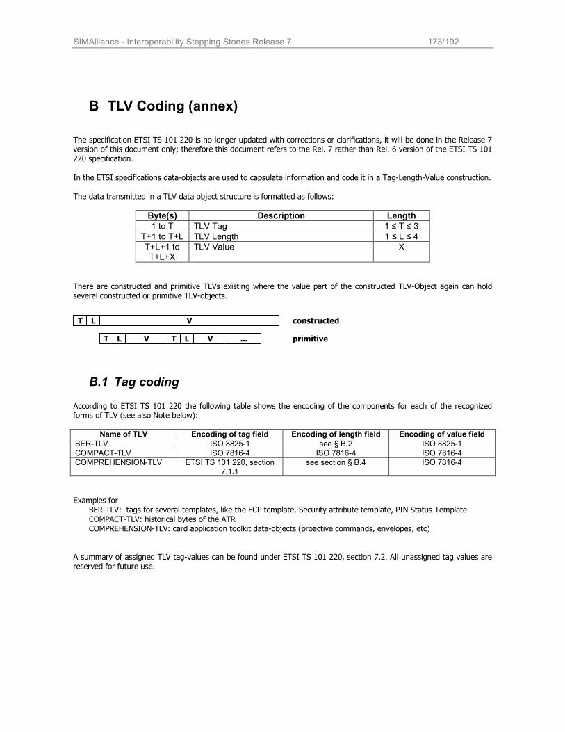
SIMAlliance - Interoperability Stepping Stones Release 7 173/192
B TLV Coding (annex)
The specification ETSI TS 101 220 is no longer updated with corrections or clarifications, it will be done in the Release 7 version of this document only; therefore this document refers to the Rel. 7 rather than Rel. 6 version of the ETSI TS 101
220 specification. In the ETSI specifications data-objects are used to capsulate information and code it in a Tag-Length-Value construction. The data transmitted in a TLV data object structure is formatted as follows:
Byte(s) Description Length
1 to T TLV Tag 1 ≤ T ≤ 3
T+1 to T+L TLV Length 1 ≤ L ≤ 4
T+L+1 to T+L+X
TLV Value X
There are constructed and primitive TLVs existing where the value part of the constructed TLV-Object again can hold several constructed or primitive TLV-objects.
T L V
T L V T L V ...
constructed
primitive
B.1 Tag coding
According to ETSI TS 101 220 the following table shows the encoding of the components for each of the recognized forms of TLV (see also Note below):
Name of TLV Encoding of tag field Encoding of length field Encoding of value field
BER-TLV ISO 8825-1 see § B.2 ISO 8825-1
COMPACT-TLV ISO 7816-4 ISO 7816-4 ISO 7816-4
COMPREHENSION-TLV ETSI TS 101 220, section 7.1.1
see section § B.4 ISO 7816-4
Examples for
BER-TLV: tags for several templates, like the FCP template, Security attribute template, PIN Status Template COMPACT-TLV: historical bytes of the ATR COMPREHENSION-TLV: card application toolkit data-objects (proactive commands, envelopes, etc)
A summary of assigned TLV tag-values can be found under ETSI TS 101 220, section 7.2. All unassigned tag values are reserved for future use.
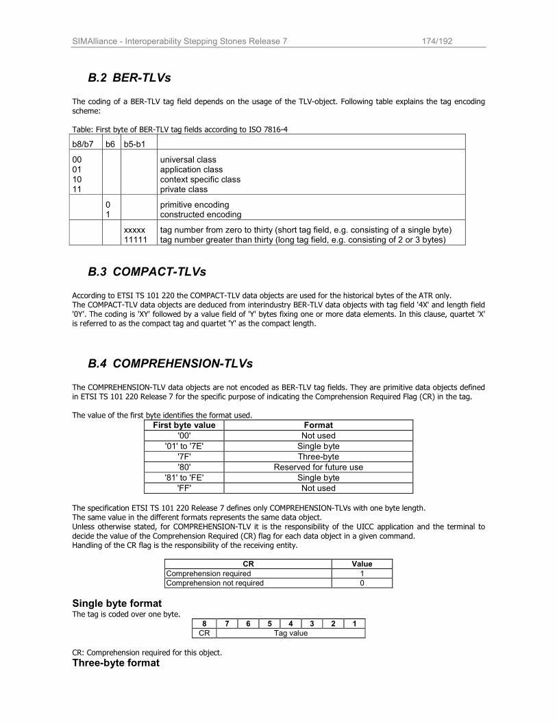
SIMAlliance - Interoperability Stepping Stones Release 7 174/192
B.2 BER-TLVs The coding of a BER-TLV tag field depends on the usage of the TLV-object. Following table explains the tag encoding
scheme:
Table: First byte of BER-TLV tag fields according to ISO 7816-4
b8/b7 b6 b5-b1
00 01 10 11
universal class application class context specific class private class
0 1
primitive encoding constructed encoding
xxxxx 11111
tag number from zero to thirty (short tag field, e.g. consisting of a single byte) tag number greater than thirty (long tag field, e.g. consisting of 2 or 3 bytes)
B.3 COMPACT-TLVs
According to ETSI TS 101 220 the COMPACT-TLV data objects are used for the historical bytes of the ATR only. The COMPACT-TLV data objects are deduced from interindustry BER-TLV data objects with tag field '4X' and length field '0Y'. The coding is 'XY' followed by a value field of 'Y' bytes fixing one or more data elements. In this clause, quartet 'X' is referred to as the compact tag and quartet 'Y' as the compact length.
B.4 COMPREHENSION-TLVs The COMPREHENSION-TLV data objects are not encoded as BER-TLV tag fields. They are primitive data objects defined in ETSI TS 101 220 Release 7 for the specific purpose of indicating the Comprehension Required Flag (CR) in the tag.
The value of the first byte identifies the format used.
First byte value Format
'00' Not used
'01' to '7E' Single byte
'7F' Three-byte
'80' Reserved for future use
'81' to 'FE' Single byte
'FF' Not used
The specification ETSI TS 101 220 Release 7 defines only COMPREHENSION-TLVs with one byte length. The same value in the different formats represents the same data object. Unless otherwise stated, for COMPREHENSION-TLV it is the responsibility of the UICC application and the terminal to
decide the value of the Comprehension Required (CR) flag for each data object in a given command. Handling of the CR flag is the responsibility of the receiving entity.
CR Value
Comprehension required 1
Comprehension not required 0
Single byte format The tag is coded over one byte.
8 7 6 5 4 3 2 1
CR Tag value
CR: Comprehension required for this object.
Three-byte format

SIMAlliance - Interoperability Stepping Stones Release 7 175/192
The tag is coded over three bytes.
Byte 1 Byte 2 Byte 3
8 7 6 5 4 3 2 1
Tag value format = '7F' CR Tag value
Tag value format: Byte 1 equal to '7F' indicates that the tag is in the three-byte format.
CR: Comprehension required for this object. Use and coding is the same as in single byte format. Tag value: Coded over 15 bits, with bit 7 of byte 2 as the most significant bit. Range from '00 01' to '7F FF'.
B.5 Length coding The length of the TLV objects is coded on one to four bytes, depending on the amount of bytes coded in the value-part.
As defined in section 7.2 of ETSI TS 101 220 seperate rules apply for the length-coding of :
COMPACT-TLV: The maximum length of the value part is limited to 65535 bytes and therefore maximum 3 lengths bytes are allowed according to ISO 7816-4.
BER-TLV and COMREHENSION-TLV
For BER-TLV and COMPREHENSION-TLV data-objects a maximum number of 4 length-bytes is allowed.
Length Byte 1 Byte 2 Byte 3 Byte 4
0-127 length ('00' to '7F') not present not present not present
128-255 '81' length ('80' to 'FF') not present not present
256-65535 '82' length ('01 00' to 'FF FF') not present
65536 - 16777215 '83' length ('01 00 00' to 'FF FF FF')
Note: Even if ETSI TS 101 220 refers to BER coding with this table, the correct naming would be DER (distinguished encoding
rules) coding, which is a subset of BER. With DER it is mandatory to use the shortest possible length coding. E.g. if you want to code T='C0', V= 'AA BB CC', following rules apply:
'C0 81 03 AA BB CC' (valid BER coding according to ISO 7816-4 but not allowed for ETSI TS 101 220) 'C0 03 AA BB CC' (valid DER coding according to ISO 8825-1, mandated in ETSI TS 101 220)
B.6 Value coding The value of a TLV is defined in the appropriate section of the ETSI specification, where the functionality or the tag-field
is described.
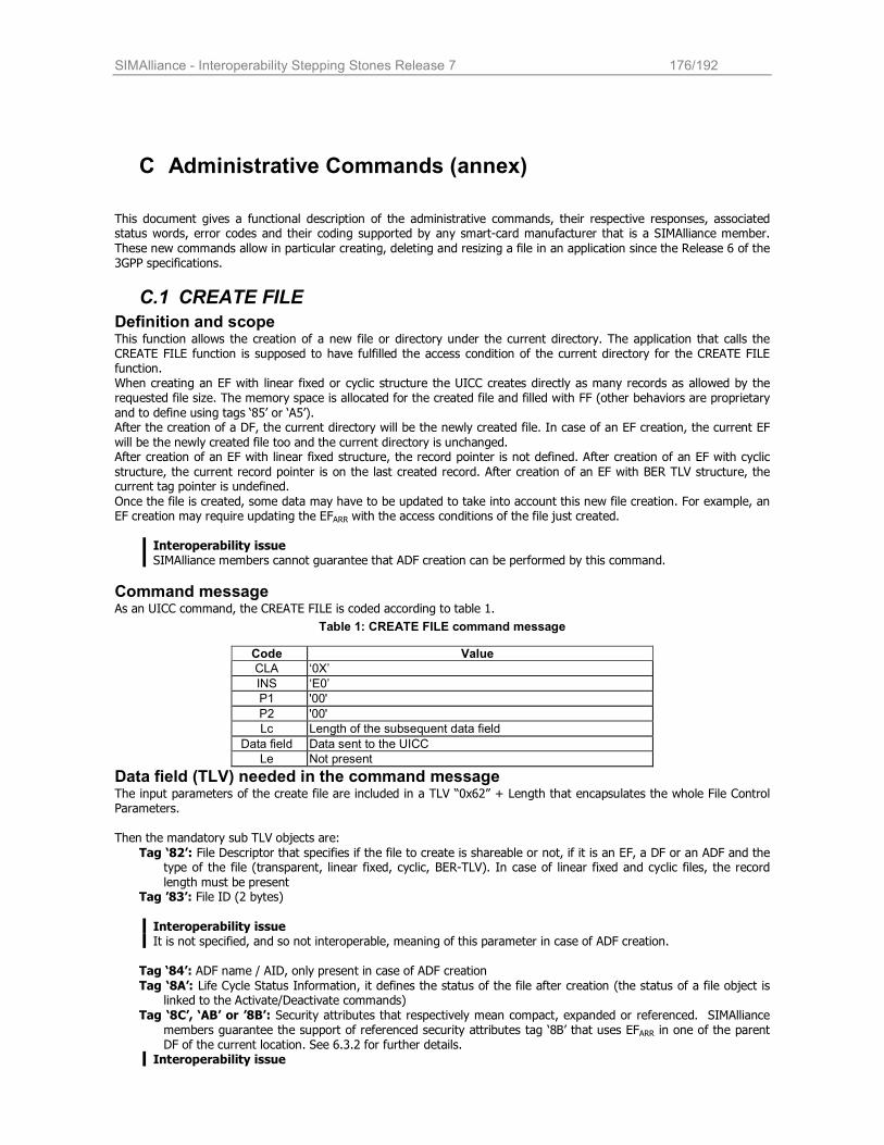
SIMAlliance - Interoperability Stepping Stones Release 7 176/192
C Administrative Commands (annex)
This document gives a functional description of the administrative commands, their respective responses, associated status words, error codes and their coding supported by any smart-card manufacturer that is a SIMAlliance member.
These new commands allow in particular creating, deleting and resizing a file in an application since the Release 6 of the 3GPP specifications.
C.1 CREATE FILE
Definition and scope This function allows the creation of a new file or directory under the current directory. The application that calls the CREATE FILE function is supposed to have fulfilled the access condition of the current directory for the CREATE FILE function. When creating an EF with linear fixed or cyclic structure the UICC creates directly as many records as allowed by the requested file size. The memory space is allocated for the created file and filled with FF (other behaviors are proprietary
and to define using tags ‘85’ or ‘A5’). After the creation of a DF, the current directory will be the newly created file. In case of an EF creation, the current EF
will be the newly created file too and the current directory is unchanged. After creation of an EF with linear fixed structure, the record pointer is not defined. After creation of an EF with cyclic
structure, the current record pointer is on the last created record. After creation of an EF with BER TLV structure, the current tag pointer is undefined.
Once the file is created, some data may have to be updated to take into account this new file creation. For example, an EF creation may require updating the EFARR with the access conditions of the file just created.
Interoperability issue SIMAlliance members cannot guarantee that ADF creation can be performed by this command.
Command message As an UICC command, the CREATE FILE is coded according to table 1.
Table 1: CREATE FILE command message
Code Value
CLA ‘0X’
INS ‘E0’
P1 '00'
P2 '00'
Lc Length of the subsequent data field
Data field Data sent to the UICC
Le Not present
Data field (TLV) needed in the command message The input parameters of the create file are included in a TLV “0x62” + Length that encapsulates the whole File Control Parameters.
Then the mandatory sub TLV objects are:
Tag ‘82’: File Descriptor that specifies if the file to create is shareable or not, if it is an EF, a DF or an ADF and the type of the file (transparent, linear fixed, cyclic, BER-TLV). In case of linear fixed and cyclic files, the record
length must be present Tag ’83’: File ID (2 bytes)
Interoperability issue It is not specified, and so not interoperable, meaning of this parameter in case of ADF creation.
Tag ‘84’: ADF name / AID, only present in case of ADF creation
Tag ‘8A’: Life Cycle Status Information, it defines the status of the file after creation (the status of a file object is linked to the Activate/Deactivate commands)
Tag ‘8C’, ‘AB’ or ’8B’: Security attributes that respectively mean compact, expanded or referenced. SIMAlliance members guarantee the support of referenced security attributes tag ‘8B’ that uses EFARR in one of the parent DF of the current location. See 6.3.2 for further details.
Interoperability issue
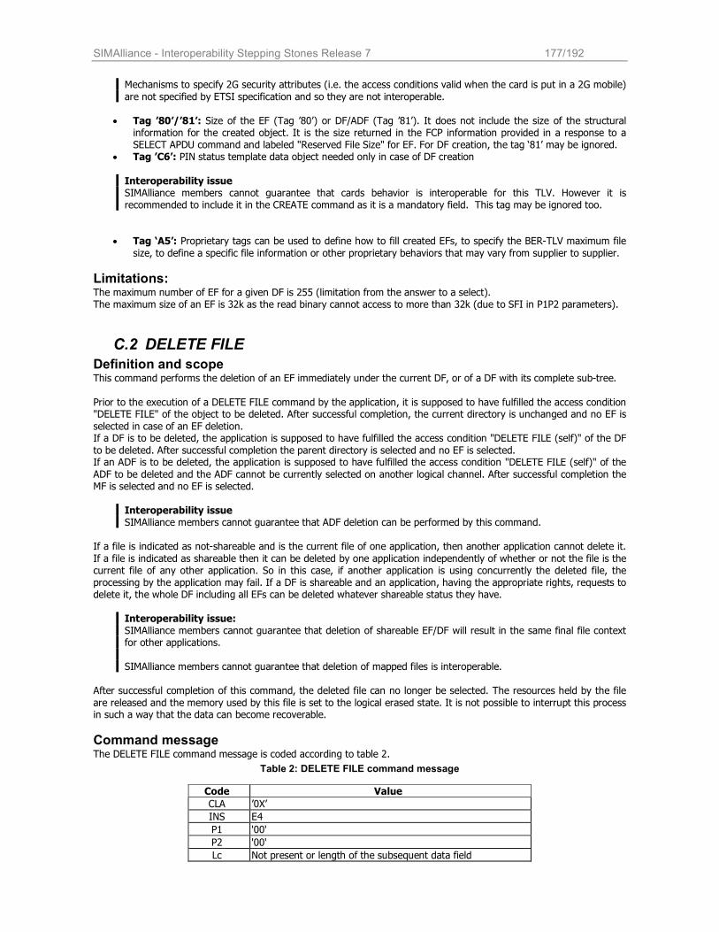
SIMAlliance - Interoperability Stepping Stones Release 7 177/192
Mechanisms to specify 2G security attributes (i.e. the access conditions valid when the card is put in a 2G mobile)
are not specified by ETSI specification and so they are not interoperable.
• Tag ’80’/’81’: Size of the EF (Tag ’80’) or DF/ADF (Tag ’81’). It does not include the size of the structural information for the created object. It is the size returned in the FCP information provided in a response to a SELECT APDU command and labeled "Reserved File Size" for EF. For DF creation, the tag ‘81’ may be ignored.
• Tag ’C6’: PIN status template data object needed only in case of DF creation
Interoperability issue SIMAlliance members cannot guarantee that cards behavior is interoperable for this TLV. However it is recommended to include it in the CREATE command as it is a mandatory field. This tag may be ignored too.
• Tag ‘A5’: Proprietary tags can be used to define how to fill created EFs, to specify the BER-TLV maximum file
size, to define a specific file information or other proprietary behaviors that may vary from supplier to supplier.
Limitations: The maximum number of EF for a given DF is 255 (limitation from the answer to a select). The maximum size of an EF is 32k as the read binary cannot access to more than 32k (due to SFI in P1P2 parameters).
C.2 DELETE FILE
Definition and scope This command performs the deletion of an EF immediately under the current DF, or of a DF with its complete sub-tree.
Prior to the execution of a DELETE FILE command by the application, it is supposed to have fulfilled the access condition "DELETE FILE" of the object to be deleted. After successful completion, the current directory is unchanged and no EF is
selected in case of an EF deletion. If a DF is to be deleted, the application is supposed to have fulfilled the access condition "DELETE FILE (self)" of the DF
to be deleted. After successful completion the parent directory is selected and no EF is selected. If an ADF is to be deleted, the application is supposed to have fulfilled the access condition "DELETE FILE (self)" of the
ADF to be deleted and the ADF cannot be currently selected on another logical channel. After successful completion the MF is selected and no EF is selected.
Interoperability issue SIMAlliance members cannot guarantee that ADF deletion can be performed by this command.
If a file is indicated as not-shareable and is the current file of one application, then another application cannot delete it.
If a file is indicated as shareable then it can be deleted by one application independently of whether or not the file is the current file of any other application. So in this case, if another application is using concurrently the deleted file, the processing by the application may fail. If a DF is shareable and an application, having the appropriate rights, requests to delete it, the whole DF including all EFs can be deleted whatever shareable status they have.
Interoperability issue: SIMAlliance members cannot guarantee that deletion of shareable EF/DF will result in the same final file context for other applications.
SIMAlliance members cannot guarantee that deletion of mapped files is interoperable.
After successful completion of this command, the deleted file can no longer be selected. The resources held by the file
are released and the memory used by this file is set to the logical erased state. It is not possible to interrupt this process in such a way that the data can become recoverable.
Command message The DELETE FILE command message is coded according to table 2.
Table 2: DELETE FILE command message
Code Value
CLA ’0X’
INS E4
P1 '00'
P2 '00'
Lc Not present or length of the subsequent data field
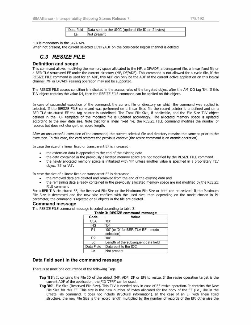
SIMAlliance - Interoperability Stepping Stones Release 7 178/192
Data field Data sent to the UICC (optional file ID on 2 bytes)
Le Not present
FID is mandatory in the JAVA API. When not present, the current selected EF/DF/ADF on the considered logical channel is deleted.
C.3 RESIZE FILE
Definition and scope This command allows modifying the memory space allocated to the MF, a DF/ADF, a transparent file, a linear fixed file or a BER-TLV structured EF under the current directory (MF, DF/ADF). This command is not allowed for a cyclic file. If the
RESIZE FILE command is used for an ADF, this ADF can only be the ADF of the current active application on this logical channel. MF or DF/ADF resizing operation may not be supported. The RESIZE FILE access condition is indicated in the access rules of the targeted object after the AM_DO tag '84'. If this TLV object contains the value D4, then the RESIZE FILE command can be applied on this object.
In case of successful execution of the command, the current file or directory on which the command was applied is selected. If the RESIZE FILE command was performed on a linear fixed file the record pointer is undefined and on a BER-TLV structured EF the tag pointer is undefined. The Total File Size, if applicable, and the File Size TLV object
defined in the FCP template of the modified file is updated accordingly. The allocated memory space is updated according to the new data size. Note that for a linear fixed file, the RESIZE FILE command modifies the number of
records but does not change the record length.
After an unsuccessful execution of the command, the current selected file and directory remains the same as prior to the execution. In this case, the card restores the previous context (the resize command is an atomic operation).
In case the size of a linear fixed or transparent EF is increased:
• the extension data is appended to the end of the existing data
• the data contained in the previously allocated memory space are not modified by the RESIZE FILE command • the newly allocated memory space is initialized with 'FF' unless another value is specified in a proprietary TLV
object ‘85’ or ‘A5’.
In case the size of a linear fixed or transparent EF is decreased: • the removed data are deleted and removed from the end of the existing data and • the remaining data already contained in the previously allocated memory space are not modified by the RESIZE
FILE command For a BER-TLV structured EF, the Reserved File Size or the Maximum File Size or both can be resized. If the Maximum File Size is decreased and the new size conflicts with the used size, then depending on the mode chosen in P1 parameter, the command is rejected or all objects in the file are deleted.
Command message The RESIZE FILE command message is coded according to table 3.
Table 3: RESIZE command message Code Value
CLA ’8X’
INS ‘D4’
P1 ‘00’ (or ‘0’ for BER-TLV EF – mode selection)
P2 '00'
Lc Length of the subsequent data field
Data Field Data sent to the ICC
Le Not present
Data field sent in the command message There is at most one occurrence of the following Tags.
Tag '83': It contains the File ID of the object (MF, ADF, DF or EF) to resize. If the resize operation target is the current ADF of the application, the FID '7FFF' can be used.
Tag '80': File Size (Reserved File Size). This TLV is needed only in case of EF resize operation. It contains the New File Size for this EF. This size is the new number of bytes allocated for the body of the EF (i.e., like in the Create File command, it does not include structural information). In the case of an EF with linear fixed structure, the new File Size is the record length multiplied by the number of records of the EF; otherwise the
SIMAlliance - Interoperability Stepping Stones Release 7 179/192
command is rejected (see previous note). This New File Size low limit is at least the size needed by one record.
For transparent files, if this size is set to '00', all the content of the EF is removed but the EF is not deleted (it is then exactly as if the EF was created with a size set to '00') and the structural information is still available. For
BER-TLV structured EF, if File Size is present, it indicates the minimum number of bytes reserved for the body of the file. The value includes administrative overhead (if any) that is required to store TLV objects, but not the structural information for the file itself. The current content of the file remains still the same whatever is the new reserved file size value (in case of increase of the current file size, below is the decrease case).
Tag '81': Total File Size. This TLV is only used in case of MF or a DF/ADF resize operation. It contains the New
Total File Size for the MF or this DF/ADF. This size is the new amount of physical memory allocated for the MF or a DF/ADF (i.e. it does not include structural information) for card not implementing dynamic allocation of
memory. The amount of EFs or DFs which may be created is implementation dependent. The MF or DF/ADF can be resized to '00' only if it does not contain any file. In this case, the structural information is still available for the MF or DF/ADF. For an ADF, the resizing to '00' does not affect EFDIR and any other information
necessary to administer an application.
After tag 'A5', there can be some other optional or proprietary TLV objects, for example to define with which pattern use to fill the created space resizing an object with a higher size. The full support of these features may vary from a card supplier to another.
About the optional sub TLV object with tag ‘86’ (Maximum File Size for a BER-TLV structured EF located inside the TLV beginning by ‘A5’), this TLV object will only be provided if a BER-TLV structured EF is resized. The Maximum File Size indicates the new maximum number of bytes that can be allocated for the body of the file. As previously, this value includes administrative overhead (if any) that is required to store TLV objects, but not the structural information for the file itself.
In case the New Maximum File Size is decreased and the size used by the existing TLV is greater than the New Maximum
File Size: • If P1 indicates Mode 0, all existing TLV objects are deleted (the file itself is not deleted). The New Maximum
File Size is assigned to the file. • If P1 indicates Mode 1, no action is performed and it returns an error telling the conditions of use are not
satisfied.
SIMAlliance - Interoperability Stepping Stones Release 7 180/192
D Interoperable formats for Java Card packages (Annex)
D.1 Introduction Currently there is no Java Card™ specification mandating a file format to represent Java Card packages, but two specific formats have been widely adopted by the industry in the last years: the CAP and the IJC formats. The two formats are hence described.
D.2 Definition of the CAP file format The CAP (converted applet) file format is defined by SUN as the deployment format for the Java Card applications and
libraries. The CAP file consists in a set of components stored in a JAR file produced by the SUN Java Card Converter. The CAP
file components are the Java Card binary data representing the classes of a single Java package. Each component describes an element of the CAP file. The following components are defined: Header, Directory, Applet, Import, Constant Pool, Class, Method, Static Field, Reference Location, Export, Descriptor and Debug components. Each CAP file component is stored in a specific file. The name of this file is given by the name of the component itself (Header.cap, Directory.cap, Import.cap, etc). Custom components can also be defined. All these files are stored in the JAR file that is produced by the SUN converter but with the extension .cap.
Example: MyApplet.cap is a JAR file containing the following files: applet.cap, class.cap, constantpool.cap, descriptor.cap,
directory.cap, header.cap, import.cap, method.cap, reflocation.cap, staticfield.cap.
Some CAP file components are optional. Some optional components are used on-card, some are used off-card.
- Applet.cap is required on-card and is generated only if the package defines one or more applets. - Export.cap is required on-card only if other packages may import elements of this package - Descriptor.cap may be used or ignored on-card. - Custom.cap may be used or ignored on-card
- Debug.cap may be used off-card by a software development environment for the debugging.
The SUN specification doesn’t define any load format or installation protocol. But SUN recommends loading the different CAP file components in the order defined by the table 21 of the SUN Javacard 2.2.1 VM specification either for
interoperability and minimum resource consumption. Global Platform defines the commands used for the installation, as described in § 21.
D.3 Definition of the IJC format
The .IJC (Interoperable Javacard CAP) file is a serialization of the different CAP file components that should be loaded on the card. The different components are ordered according to SUN specification recommendation. The .IJC file is in fact a stream of byte ready to be split in the different Load commands defined by Global Platform. The CAP file components that are not required to be loaded on the card are removed:
• The components used for off-card entities are removed. This is the case of the debug component
The optional components not required for the loading may be removed: descriptor component and customs components are removed. It reduces the amount of free memory required on the cards and also the number of SMS used for OTA applet download. It may be included when required by the card.
SIMAlliance - Interoperability Stepping Stones Release 7 181/192
E Examples of Release 6 Toolkit Applets (annex)
This section contains two different examples of Release 6 Toolkit Applets showing the power of the new features of the Release 6.
The examples are fully interoperable with any SIM Alliance Release 6 compliant card and they can be downloaded and tested with any phase 2+ mobile handset compatible.
E.1 Menu Resizer
Introduction The Menu Resizer is a simple toolkit application with one first level menu entry, with a user text set as “Change title”. Once the user selects the menu entry, a user prompt with a notifying text “Insert the new title” requests the user to type
a new text for the USIM Menu.
The application updates the menu title with the new text provided by the user and, if required, changes the size of the file containing the menu title (EFSUME) to the appropriate size.
This application is able to prove Release 6 file access and administration API (resize command), usage of Global Buffer,
BER TLV handlers.
Application behavior Applet installation The application allocates a first level menu item during applet installation, after the application registration; this operation registers also the application to the event menu selection. tkRegistry = ToolkitRegistrySystem.getEntry(); // Registering to the toolkit tkRegistry.initMenuEntry(menuTitle, (short)0, (short)menuTitle.length, (byte)0, // Next action false, // Help supported (byte)0, // Icon Qualifier (short)0); // Icon Identifier
Then the file EF SUME (’6F54’) under the DF_TELECOM (’7F10’) is selected during applet installation; it contains the
menu text,; it is suggested to invoke the “FileViewBuilder” object only during applet installation as it allocates a new memory object.
Also an administration file view object is allocated and it selects the DF TELECOM during applet installation; this object is used to perform administrative operations (resize). Note that the files are selected only at this stage and they are not selected anymore during application lifetime. fvEF_DF_TELECOM = AdminFileViewBuilder. getTheUICCAdminFileView(JCSystem.NOT_A_TRANSIENT_OBJECT); fvEF_SUME = UICCSystem.getTheUICCView(JCSystem.NOT_A_TRANSIENT_OBJECT); fvEF_SUME.select(UICCConstants.FID_DF_TELECOM); fvEF_SUME.select(FID_EF_SUME); fvEF_DF_TELECOM.select(UICCConstants.FID_DF_TELECOM);
The last operation is allocating a TLV handler object, to be used for resizing operation; also in this case, due to the memory consumption associated to this operation, it is better to invoke this method only at installation time: // The edit handler is allocated with exactly size of the Resize Command template editHandler = (EditHandler)HandlerBuilder.buildTLVHandler(HandlerBuilder.EDIT_HANDLER, (short)resizeCommand.length);
SIMAlliance - Interoperability Stepping Stones Release 7 182/192
Operative behavior
The application can be triggered only by menu selection event; the user is prompted to insert a new menu title by issuing a Get Input proactive command: // The user is prompted with a get input to change the menu title ProactiveHandler proh = ProactiveHandlerSystem.getTheHandler(); // Note: missing 8_BIT_DATA from ETSI - used 0x04 proh.initGetInput( (byte)0x00, (byte)0x04, insertNewTitle_text, (short)0, (short)insertNewTitle_text.length, (short)1, (short)20 ); res = proh.send();
If the user accepts to change the event, the inputted text is retrieved by the Proactive Response Handler and an Alpha Identifier TLV is built by setting the menu title: // If the user presses ok... if (res == (byte)0x00) { // The text is retrieved by the Proactive Response Handler ProactiveResponseHandler proresh = ProactiveResponseHandlerSystem.
getTheHandler(); // To perform copy operation, the Volatile Byte Array is used (no memory
// allocation) globalBuffer = UICCPlatform.getTheVolatileByteArray(); dataLen = proresh.copyTextString(globalBuffer, (short)2); // Data is stored inside the Menu Resize in a T-L-V structure globalBuffer[0] = ToolkitConstants.TAG_ALPHA_IDENTIFIER; globalBuffer[1] = (byte)(dataLen-2); // The file is resized to exactly fit the buffer resizeMenuFile(dataLen); // File content is updated fvEF_SUME.updateBinary((short)0, globalBuffer, (short)0, dataLen); }
Before updating the file content, a Resize operation is performed on the file size in order to let the new content fitting. To simplify the building of the Resize command, the array containing the structure of the resize command is pre-stored
in the application, and only the size field is set. // The new length is set in the byte array Util.setShort(resizeCommand, FILE_LENGTH_OFFSET, newFileLength); editHandler.clear(); editHandler.appendArray(resizeCommand, (short)0, (short)resizeCommand.length); // The resize operation is performed fvEF_DF_TELECOM.resizeFile(editHandler);
Installation parameters The following installation parameters are required: UICC Toolkit Specific Parameters - One menu item must be allocated
UICC Access Application specific parameters field - The update binary operation on EF SUME must be granted; the condition to be fulfilled depends on card
configuration.
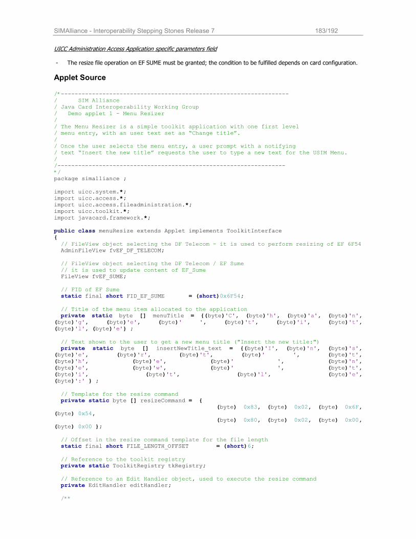
SIMAlliance - Interoperability Stepping Stones Release 7 183/192
UICC Administration Access Application specific parameters field - The resize file operation on EF SUME must be granted; the condition to be fulfilled depends on card configuration.
Applet Source /*------------------------------------------------------------------ / SIM Alliance / Java Card Interoperability Working Group / Demo applet 1 - Menu Resizer / / The Menu Resizer is a simple toolkit application with one first level / menu entry, with an user text set as “Change title”. / / Once the user selects the menu entry, a user prompt with a notifying / text “Insert the new title” requests the user to type a new text for the USIM Menu. / /------------------------------------------------------------------ */ package simalliance ; import uicc.system.*; import uicc.access.*; import uicc.access.fileadministration.*; import uicc.toolkit.*; import javacard.framework.*; public class menuResize extends Applet implements ToolkitInterface { // FileView object selecting the DF Telecom - it is used to perform resizing of EF 6F54 AdminFileView fvEF_DF_TELECOM; // FileView object selecting the DF Telecom / EF Sume // it is used to update content of EF_Sume FileView fvEF_SUME; // FID of EF Sume static final short FID_EF_SUME = (short)0x6F54; // Title of the menu item allocated to the application private static byte [] menuTitle = {(byte)'C', (byte)'h', (byte)'a', (byte)'n', (byte)'g', (byte)'e', (byte)' ', (byte)'t', (byte)'i', (byte)'t', (byte)'l', (byte)'e'} ; // Text shown to the user to get a new menu title ("Insert the new title:") private static byte [] insertNewTitle_text = {(byte)'I', (byte)'n', (byte)'s', (byte)'e', (byte)'r', (byte)'t', (byte)' ', (byte)'t', (byte)'h', (byte)'e', (byte)' ', (byte)'n', (byte)'e', (byte)'w', (byte)' ', (byte)'t', (byte)'i', (byte)'t', (byte)'l', (byte)'e', (byte)':' } ; // Template for the resize command private static byte [] resizeCommand = { (byte) 0x83, (byte) 0x02, (byte) 0x6F, (byte) 0x54, (byte) 0x80, (byte) 0x02, (byte) 0x00, (byte) 0x00 }; // Offset in the resize command template for the file length static final short FILE_LENGTH_OFFSET = (short)6; // Reference to the toolkit registry private static ToolkitRegistry tkRegistry; // Reference to an Edit Handler object, used to execute the resize command private EditHandler editHandler; /**
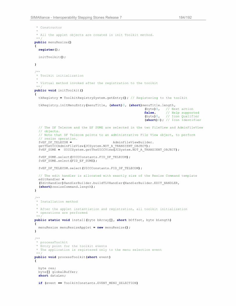
SIMAlliance - Interoperability Stepping Stones Release 7 184/192
* Constructor * * All the applet objects are created in init Toolkit method. **/ public menuResize() { register(); initToolkit(); } /** * Toolkit initialization * * Virtual method invoked after the registration to the toolkit **/ public void initToolkit() { tkRegistry = ToolkitRegistrySystem.getEntry(); // Registering to the toolkit tkRegistry.initMenuEntry(menuTitle, (short)0, (short)menuTitle.length, (byte)0, // Next action false, // Help supported (byte)0, // Icon Qualifier (short)0); // Icon Identifier // The DF Telecom and the EF SUME are selected in the two FileView and AdminFileView // objects. // Note that DF Telecom points to an administrative File View object, to perform // resize operation. fvEF_DF_TELECOM = AdminFileViewBuilder. getTheUICCAdminFileView(JCSystem.NOT_A_TRANSIENT_OBJECT); fvEF_SUME = UICCSystem.getTheUICCView(JCSystem.NOT_A_TRANSIENT_OBJECT); fvEF_SUME.select(UICCConstants.FID_DF_TELECOM); fvEF_SUME.select(FID_EF_SUME); fvEF_DF_TELECOM.select(UICCConstants.FID_DF_TELECOM); // The edit handler is allocated with exactly size of the Resize Command template editHandler = (EditHandler)HandlerBuilder.buildTLVHandler(HandlerBuilder.EDIT_HANDLER, (short)resizeCommand.length); } /** * Installation method * * After the applet instantiation and registration, all toolkit initialization * operations are performed **/ public static void install(byte bArray[], short bOffset, byte bLength) { menuResize menuResizeApplet = new menuResize(); } /** * processToolkit * Entry point for the toolkit events * The application is registered only to the menu selection event **/ public void processToolkit(short event) { byte res; byte[] globalBuffer; short dataLen; if (event == ToolkitConstants.EVENT_MENU_SELECTION)
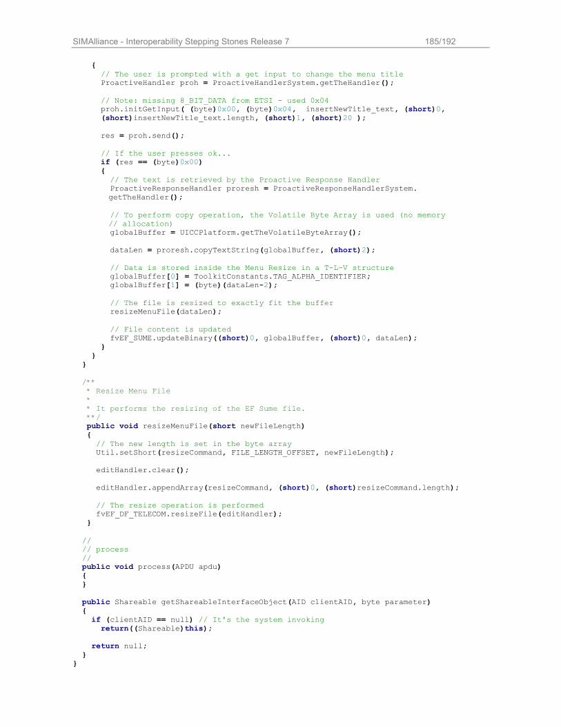
SIMAlliance - Interoperability Stepping Stones Release 7 185/192
{ // The user is prompted with a get input to change the menu title ProactiveHandler proh = ProactiveHandlerSystem.getTheHandler(); // Note: missing 8_BIT_DATA from ETSI - used 0x04 proh.initGetInput( (byte)0x00, (byte)0x04, insertNewTitle_text, (short)0, (short)insertNewTitle_text.length, (short)1, (short)20 ); res = proh.send(); // If the user presses ok... if (res == (byte)0x00) { // The text is retrieved by the Proactive Response Handler ProactiveResponseHandler proresh = ProactiveResponseHandlerSystem.
getTheHandler(); // To perform copy operation, the Volatile Byte Array is used (no memory
// allocation) globalBuffer = UICCPlatform.getTheVolatileByteArray(); dataLen = proresh.copyTextString(globalBuffer, (short)2); // Data is stored inside the Menu Resize in a T-L-V structure globalBuffer[0] = ToolkitConstants.TAG_ALPHA_IDENTIFIER; globalBuffer[1] = (byte)(dataLen-2); // The file is resized to exactly fit the buffer resizeMenuFile(dataLen); // File content is updated fvEF_SUME.updateBinary((short)0, globalBuffer, (short)0, dataLen); } } } /** * Resize Menu File * * It performs the resizing of the EF Sume file. **/ public void resizeMenuFile(short newFileLength) { // The new length is set in the byte array Util.setShort(resizeCommand, FILE_LENGTH_OFFSET, newFileLength); editHandler.clear(); editHandler.appendArray(resizeCommand, (short)0, (short)resizeCommand.length); // The resize operation is performed fvEF_DF_TELECOM.resizeFile(editHandler); } // // process // public void process(APDU apdu) { } public Shareable getShareableInterfaceObject(AID clientAID, byte parameter) { if (clientAID == null) // It's the system invoking return((Shareable)this); return null; } }
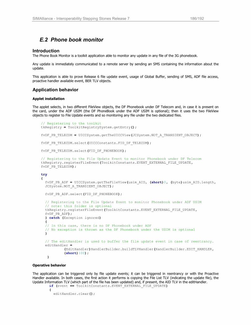
SIMAlliance - Interoperability Stepping Stones Release 7 186/192
E.2 Phone book monitor
Introduction The Phone Book Monitor is a toolkit application able to monitor any update in any file of the 3G phonebook.
Any update is immediately communicated to a remote server by sending an SMS containing the information about the
update.
This application is able to prove Release 6 file update event, usage of Global Buffer, sending of SMS, ADF file access,
proactive handler available event, BER TLV objects.
Application behavior Applet installation
The applet selects, in two different FileView objects, the DF Phonebook under DF Telecom and, in case it is present on the card, under the ADF USIM (the DF PhoneBook under the ADF USIM is optional); then it uses the two FileView
objects to register to File Update events and so monitoring any file under the two dedicated files. // Registering to the toolkit tkRegistry = ToolkitRegistrySystem.getEntry(); fvDF_PB_TELECOM = UICCSystem.getTheUICCView(JCSystem.NOT_A_TRANSIENT_OBJECT); fvDF_PB_TELECOM.select(UICCConstants.FID_DF_TELECOM); fvDF_PB_TELECOM.select(FID_DF_PHONEBOOK); // Registering to the File Update Event to monitor Phonebook under DF Telecom tkRegistry.registerFileEvent(ToolkitConstants.EVENT_EXTERNAL_FILE_UPDATE, fvDF_PB_TELECOM); try { fvDF_PB_ADF = UICCSystem.getTheFileView(usim_AID, (short)0, (byte)usim_AID.length, JCSystem.NOT_A_TRANSIENT_OBJECT); fvDF_PB_ADF.select(FID_DF_PHONEBOOK); // Registering to the File Update Event to monitor Phonebook under ADF USIM // note: this folder is optional tkRegistry.registerFileEvent(ToolkitConstants.EVENT_EXTERNAL_FILE_UPDATE, fvDF_PB_ADF); } catch (Exception ignored) { // In this case, there is no DF Phonebook under ADF // No exception is thrown as the DF Phonebook under the USIM is optional } // The editHandler is used to buffer the file update event in case of reentrancy. editHandler = (EditHandler)HandlerBuilder.buildTLVHandler(HandlerBuilder.EDIT_HANDLER, (short)100); }
Operative behavior The application can be triggered only by file update events; it can be triggered in reentrancy or with the Proactive Handler available. In both cases, the first action it performs is copying the File List TLV (indicating the update file), the Update Information TLV (which part of the file has been updated) and, if present, the AID TLV in the editHandler. if (event == ToolkitConstants.EVENT_EXTERNAL_FILE_UPDATE) { editHandler.clear();
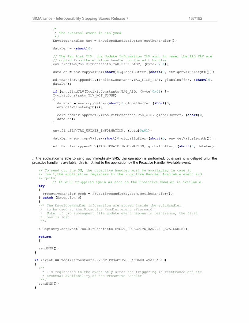
SIMAlliance - Interoperability Stepping Stones Release 7 187/192
/* * The external event is analyzed */ EnvelopeHandler env = EnvelopeHandlerSystem.getTheHandler(); dataLen = (short)0; // The Tag List TLV, the Update Information TLV and, in case, the AID TLV are // copied from the envelope handler to the edit handler env.findTLV(ToolkitConstants.TAG_FILE_LIST, (byte)0x01); dataLen = env.copyValue((short)0,globalBuffer,(short)0, env.getValueLength()); editHandler.appendTLV(ToolkitConstants.TAG_FILE_LIST, globalBuffer, (short)0, dataLen); if (env.findTLV(ToolkitConstants.TAG_AID, (byte)0x01) != ToolkitConstants.TLV_NOT_FOUND) { dataLen = env.copyValue((short)0,globalBuffer,(short)0, env.getValueLength()); editHandler.appendTLV(ToolkitConstants.TAG_AID, globalBuffer, (short)0, dataLen); } env.findTLV(TAG_UPDATE_INFORMATION, (byte)0x01); dataLen = env.copyValue((short)0,globalBuffer,(short)0, env.getValueLength()); editHandler.appendTLV(TAG_UPDATE_INFORMATION, globalBuffer, (short)0, dataLen);
If the application is able to send out immediately SMS, the operation is performed; otherwise it is delayed until the proactive handler is available; this is notified to the application by the Proactive Handler Available event. // To send out the SM, the proactive handler must be available; in case it // isn't,the application registers to the Proactive Handler Available event and // quits.
// It will triggered again as soon as the Proactive Handler is available. try { ProactiveHandler proh = ProactiveHandlerSystem.getTheHandler(); } catch (Exception e) { /** The EnvelopeHandler information are stored inside the editHandler, * to be used at the Proactive Handler event afterward * Note: if two subsequent file update event happen in reentrance, the first * one is lost **/ tkRegistry.setEvent(ToolkitConstants.EVENT_PROACTIVE_HANDLER_AVAILABLE); return; } sendSMS(); } if (event == ToolkitConstants.EVENT_PROACTIVE_HANDLER_AVAILABLE) { /** * I'm registered to the event only after the triggering in reentrance and the * eventual availability of the Proactive Handler **/ sendSMS(); }
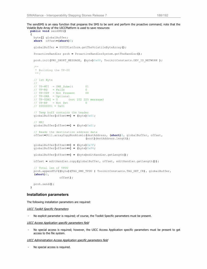
SIMAlliance - Interoperability Stepping Stones Release 7 188/192
The sendSMS is an easy function that prepares the SMS to be sent and perform the proactive command; note that the
Volatile Byte Array of the UICCPlatform is used to save resources: public void sendSMS() { byte[] globalBuffer; short offset=(short)0; globalBuffer = UICCPlatform.getTheVolatileByteArray(); ProactiveHandler proh = ProactiveHandlerSystem.getTheHandler(); proh.init(PRO_SHORT_MESSAGE, (byte)0x00, ToolkitConstants.DEV_ID_NETWORK ); /** * Building the TP-DU **/ // 1st Byte // // TP-MTI = SMS_Submit 01 // TP-RD = False 0 // TP-VPF = Not Present 00 // TP-SRR = Optional // TP-UDHI = 0 (not 102 225 message) // TP-RP = Not Set 0 // 00000001 = 0x01 // Temp buff contains the header globalBuffer[offset++] = (byte)0x01; // MRI globalBuffer[offset++] = (byte)0x01; // Reads the destination address data offset=Util.arrayCopyNonAtomic(destAddress, (short)0, globalBuffer, offset, (sort)destAddress.length); globalBuffer[offset++] = (byte)0x7F; globalBuffer[offset++] = (byte)0xF6; globalBuffer[offset++] = (byte)editHandler.getLength(); offset = editHandler.copy(globalBuffer, offset, editHandler.getLength()); // Total len of TPDU proh.appendTLV((byte)(TAG_SMS_TPDU | ToolkitConstants.TAG_SET_CR), globalBuffer, (short)0, offset); proh.send(); }
Installation parameters The following installation parameters are required:
UICC Toolkit Specific Parameters - No explicit parameter is required; of course, the Toolkit Specific parameters must be present.
UICC Access Application specific parameters field - No special access is required; however, the UICC Access Application specific parameters must be present to get
access to the file system. UICC Administration Access Application specific parameters field - No special access is required.
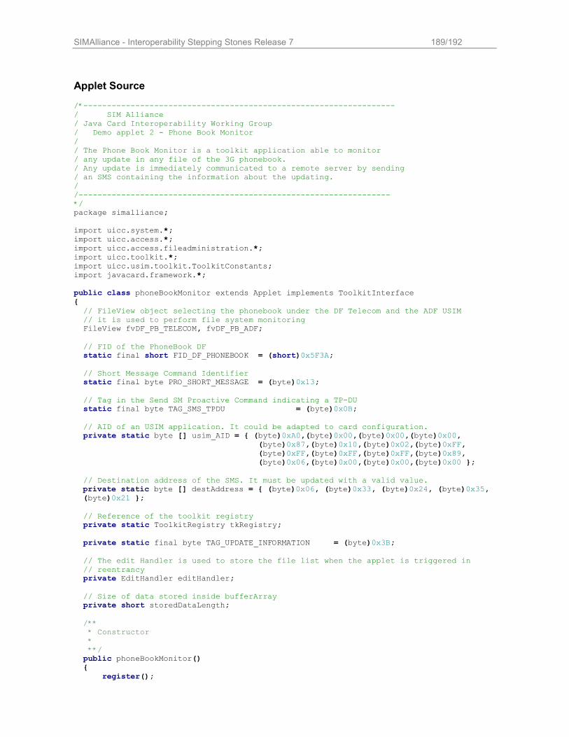
SIMAlliance - Interoperability Stepping Stones Release 7 189/192
Applet Source /*------------------------------------------------------------------ / SIM Alliance / Java Card Interoperability Working Group / Demo applet 2 - Phone Book Monitor / / The Phone Book Monitor is a toolkit application able to monitor / any update in any file of the 3G phonebook. / Any update is immediately communicated to a remote server by sending / an SMS containing the information about the updating. / /------------------------------------------------------------------ */ package simalliance; import uicc.system.*; import uicc.access.*; import uicc.access.fileadministration.*; import uicc.toolkit.*; import uicc.usim.toolkit.ToolkitConstants; import javacard.framework.*; public class phoneBookMonitor extends Applet implements ToolkitInterface { // FileView object selecting the phonebook under the DF Telecom and the ADF USIM // it is used to perform file system monitoring FileView fvDF_PB_TELECOM, fvDF_PB_ADF; // FID of the PhoneBook DF static final short FID_DF_PHONEBOOK = (short)0x5F3A; // Short Message Command Identifier static final byte PRO_SHORT_MESSAGE = (byte)0x13; // Tag in the Send SM Proactive Command indicating a TP-DU static final byte TAG_SMS_TPDU = (byte)0x0B; // AID of an USIM application. It could be adapted to card configuration. private static byte [] usim_AID = { (byte)0xA0,(byte)0x00,(byte)0x00,(byte)0x00, (byte)0x87,(byte)0x10,(byte)0x02,(byte)0xFF, (byte)0xFF,(byte)0xFF,(byte)0xFF,(byte)0x89, (byte)0x06,(byte)0x00,(byte)0x00,(byte)0x00 }; // Destination address of the SMS. It must be updated with a valid value. private static byte [] destAddress = { (byte)0x06, (byte)0x33, (byte)0x24, (byte)0x35, (byte)0x21 };
// Reference of the toolkit registry private static ToolkitRegistry tkRegistry; private static final byte TAG_UPDATE_INFORMATION = (byte)0x3B; // The edit Handler is used to store the file list when the applet is triggered in // reentrancy private EditHandler editHandler; // Size of data stored inside bufferArray private short storedDataLength; /** * Constructor * **/ public phoneBookMonitor() { register();
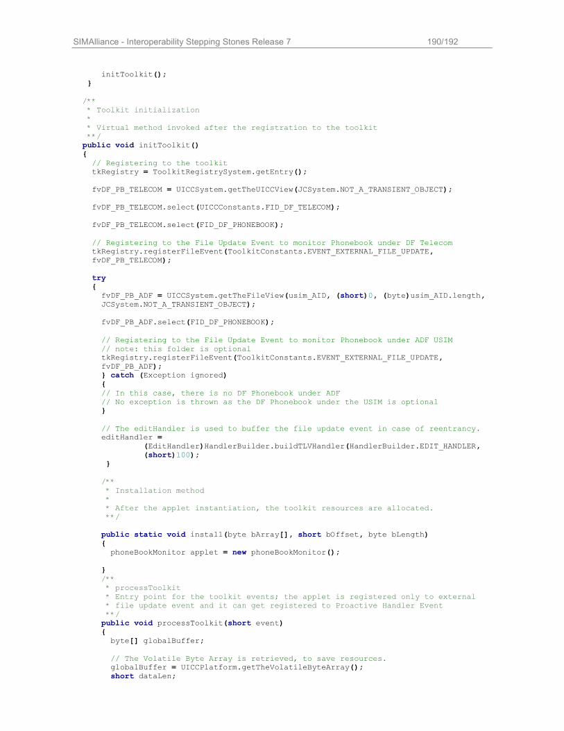
SIMAlliance - Interoperability Stepping Stones Release 7 190/192
initToolkit(); } /** * Toolkit initialization * * Virtual method invoked after the registration to the toolkit **/ public void initToolkit() { // Registering to the toolkit tkRegistry = ToolkitRegistrySystem.getEntry(); fvDF_PB_TELECOM = UICCSystem.getTheUICCView(JCSystem.NOT_A_TRANSIENT_OBJECT); fvDF_PB_TELECOM.select(UICCConstants.FID_DF_TELECOM); fvDF_PB_TELECOM.select(FID_DF_PHONEBOOK); // Registering to the File Update Event to monitor Phonebook under DF Telecom tkRegistry.registerFileEvent(ToolkitConstants.EVENT_EXTERNAL_FILE_UPDATE, fvDF_PB_TELECOM); try { fvDF_PB_ADF = UICCSystem.getTheFileView(usim_AID, (short)0, (byte)usim_AID.length, JCSystem.NOT_A_TRANSIENT_OBJECT); fvDF_PB_ADF.select(FID_DF_PHONEBOOK); // Registering to the File Update Event to monitor Phonebook under ADF USIM // note: this folder is optional tkRegistry.registerFileEvent(ToolkitConstants.EVENT_EXTERNAL_FILE_UPDATE, fvDF_PB_ADF); } catch (Exception ignored) { // In this case, there is no DF Phonebook under ADF // No exception is thrown as the DF Phonebook under the USIM is optional } // The editHandler is used to buffer the file update event in case of reentrancy. editHandler = (EditHandler)HandlerBuilder.buildTLVHandler(HandlerBuilder.EDIT_HANDLER, (short)100); } /** * Installation method * * After the applet instantiation, the toolkit resources are allocated. **/ public static void install(byte bArray[], short bOffset, byte bLength) { phoneBookMonitor applet = new phoneBookMonitor(); } /** * processToolkit * Entry point for the toolkit events; the applet is registered only to external * file update event and it can get registered to Proactive Handler Event **/ public void processToolkit(short event) { byte[] globalBuffer; // The Volatile Byte Array is retrieved, to save resources. globalBuffer = UICCPlatform.getTheVolatileByteArray(); short dataLen;
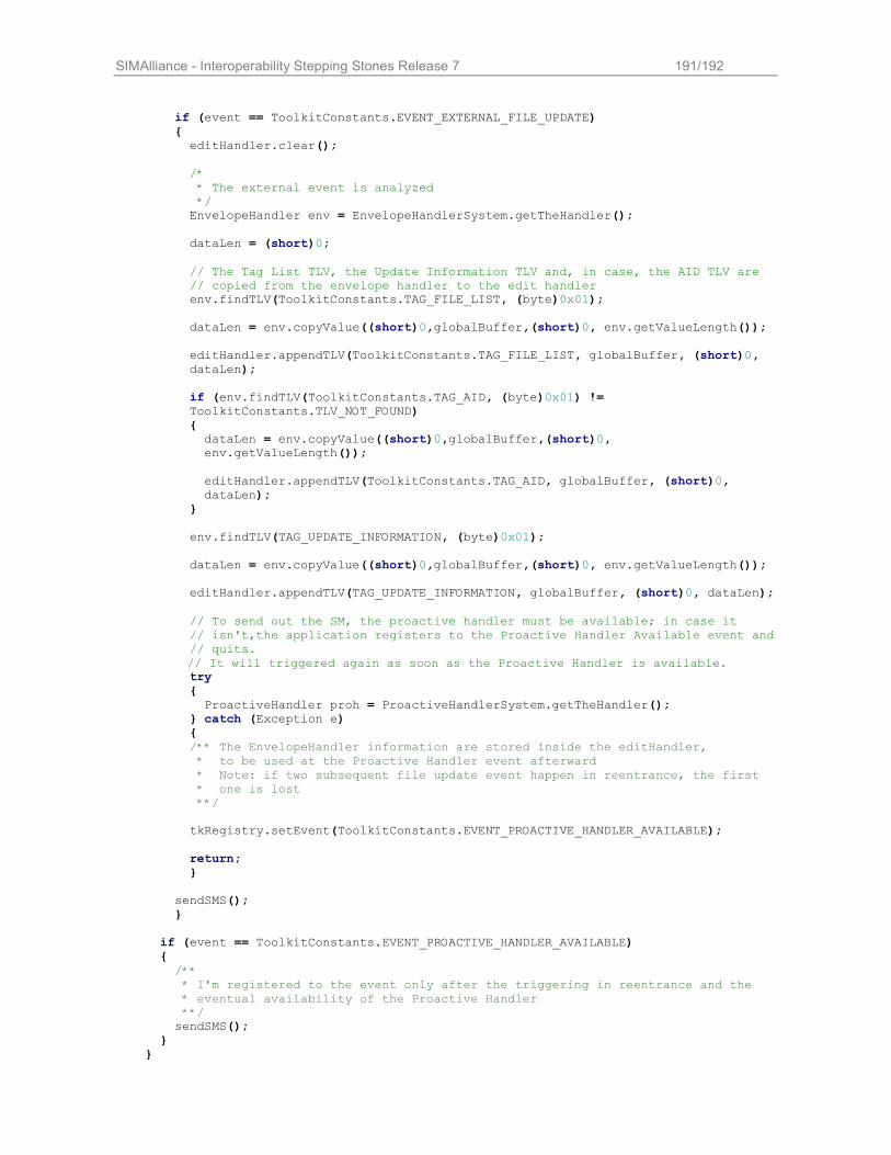
SIMAlliance - Interoperability Stepping Stones Release 7 191/192
if (event == ToolkitConstants.EVENT_EXTERNAL_FILE_UPDATE) { editHandler.clear(); /* * The external event is analyzed */ EnvelopeHandler env = EnvelopeHandlerSystem.getTheHandler(); dataLen = (short)0; // The Tag List TLV, the Update Information TLV and, in case, the AID TLV are // copied from the envelope handler to the edit handler env.findTLV(ToolkitConstants.TAG_FILE_LIST, (byte)0x01); dataLen = env.copyValue((short)0,globalBuffer,(short)0, env.getValueLength()); editHandler.appendTLV(ToolkitConstants.TAG_FILE_LIST, globalBuffer, (short)0, dataLen); if (env.findTLV(ToolkitConstants.TAG_AID, (byte)0x01) != ToolkitConstants.TLV_NOT_FOUND) { dataLen = env.copyValue((short)0,globalBuffer,(short)0, env.getValueLength()); editHandler.appendTLV(ToolkitConstants.TAG_AID, globalBuffer, (short)0, dataLen); } env.findTLV(TAG_UPDATE_INFORMATION, (byte)0x01); dataLen = env.copyValue((short)0,globalBuffer,(short)0, env.getValueLength()); editHandler.appendTLV(TAG_UPDATE_INFORMATION, globalBuffer, (short)0, dataLen); // To send out the SM, the proactive handler must be available; in case it // isn't,the application registers to the Proactive Handler Available event and // quits.
// It will triggered again as soon as the Proactive Handler is available. try { ProactiveHandler proh = ProactiveHandlerSystem.getTheHandler(); } catch (Exception e) { /** The EnvelopeHandler information are stored inside the editHandler, * to be used at the Proactive Handler event afterward * Note: if two subsequent file update event happen in reentrance, the first * one is lost **/ tkRegistry.setEvent(ToolkitConstants.EVENT_PROACTIVE_HANDLER_AVAILABLE); return; } sendSMS(); } if (event == ToolkitConstants.EVENT_PROACTIVE_HANDLER_AVAILABLE) { /** * I'm registered to the event only after the triggering in reentrance and the * eventual availability of the Proactive Handler **/ sendSMS(); } }
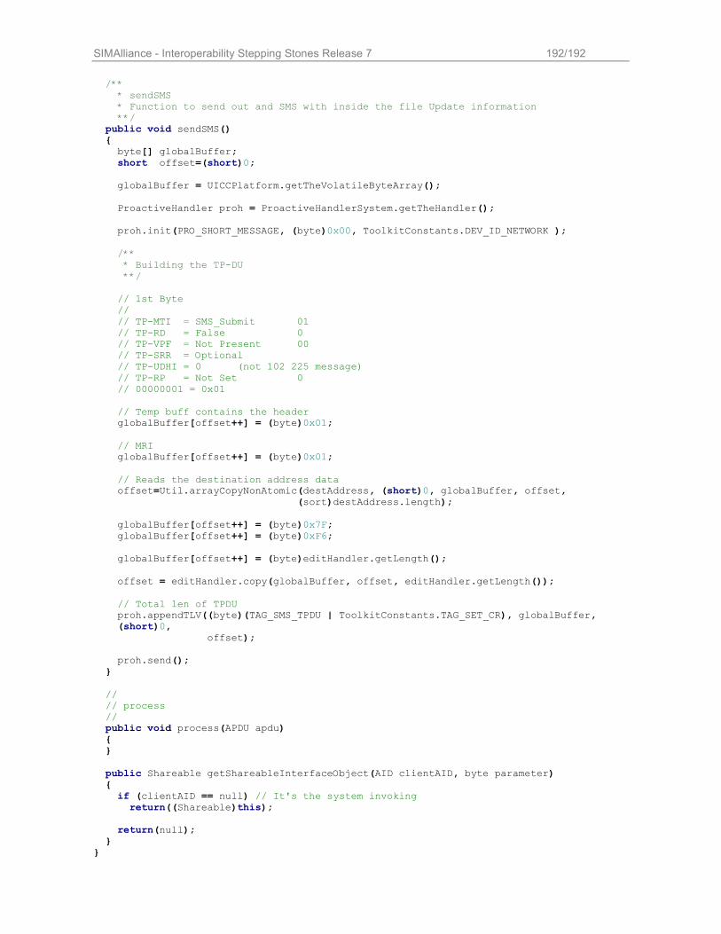
SIMAlliance - Interoperability Stepping Stones Release 7 192/192
/** * sendSMS * Function to send out and SMS with inside the file Update information **/ public void sendSMS() { byte[] globalBuffer; short offset=(short)0; globalBuffer = UICCPlatform.getTheVolatileByteArray(); ProactiveHandler proh = ProactiveHandlerSystem.getTheHandler(); proh.init(PRO_SHORT_MESSAGE, (byte)0x00, ToolkitConstants.DEV_ID_NETWORK ); /** * Building the TP-DU **/ // 1st Byte // // TP-MTI = SMS_Submit 01 // TP-RD = False 0 // TP-VPF = Not Present 00 // TP-SRR = Optional // TP-UDHI = 0 (not 102 225 message) // TP-RP = Not Set 0 // 00000001 = 0x01 // Temp buff contains the header globalBuffer[offset++] = (byte)0x01; // MRI globalBuffer[offset++] = (byte)0x01; // Reads the destination address data offset=Util.arrayCopyNonAtomic(destAddress, (short)0, globalBuffer, offset, (sort)destAddress.length); globalBuffer[offset++] = (byte)0x7F; globalBuffer[offset++] = (byte)0xF6; globalBuffer[offset++] = (byte)editHandler.getLength(); offset = editHandler.copy(globalBuffer, offset, editHandler.getLength()); // Total len of TPDU proh.appendTLV((byte)(TAG_SMS_TPDU | ToolkitConstants.TAG_SET_CR), globalBuffer, (short)0, offset); proh.send(); } // // process // public void process(APDU apdu) { } public Shareable getShareableInterfaceObject(AID clientAID, byte parameter) { if (clientAID == null) // It's the system invoking return((Shareable)this); return(null); } }


![Mobile Connect SIM Applet Interoperability Stepping Stones · 2020. 11. 16. · [16] SIMAlliance - Interoperability Stepping Stones Release 7 [17] 3GPP TS 31.111 Technical Specification](https://img.dokumen.tips/doc/110x75/60c94e6308c07461fe59da15/mobile-connect-sim-applet-interoperability-stepping-stones-2020-11-16-16.jpg)