Embed Size (px)
Citation preview

Interlogix Simon XT Installation Guide - AT&T LTEThe LTE Module for Simon XT and XTi enables wireless reporting of all alarms and other system events from theInterlogix Simon XT & XTi control panel using the LTE wireless (cellular) network. The module can be used as theprimary communication path for all alarm signaling, or as a backup to a telephone line connection to the centralmonitoring station. The wireless alarm signaling and routing service is operated by Alarm.com. The LTE Module alsofeatures integrated support for Alarm.com’s emPower™ solution with built-in Z-Wave capabilities and for Alarm.com’sImage Sensor through the built-in Image Sensor radio. Two-Way Voice is conducted over the AT&T 3G HSPA network.
The module interfaces with the Simon XT, XTi, and XTi-5 panel boards, fits into a special compartment inside thepanel. It is powered by the control panel and panel battery.
Compatibility
The LTE module is compatible with all Simon XT (version 1.3 and up) and XTi or XTi-5 control panels.
Specifications
CompatibleSimon XT panels with software versions 1.3 and laterand Simon XTi
Power requirements 6V nominal
Standby current 30mA (10mA in PowerSave Mode)
Peak current 1.7 A
Operating temperature 32 to 120°F (0 to 49°C)
Storage temperature -30 to 140°F (-34 to 60°C)
Max. relative humidity 90% non-condensing
https://answers.alarm.com/?title=ADC/Partner/Installation_and_Troubleshooting/Panels/Interlogix_Simon_XT/Interlogix_Simo…Updated: Wed, 29 Jan 2020 21:50:59 GMT
1

Cellular network LTE – AT&T, 3G HSPA – AT&T
Dimensions (H x W) 4 1/16 x 1 7/8 inches
Module diagram
Account creation
Before installing an Alarm.com LTE Module in a Simon XT, XTi, XTi-5 system, a new customer account needs to becreated with Alarm.com. It is recommended that the account be created at least 24 hours in advance of installation toensure that the radio is activated prior to installation.
To activate an account go to www.alarm.com/dealer and login. In Customers, click Create New Customer. Thefollowing customer information is required to create the account:
• Customer Address• Customer Phone Number• Customer E-mail• Preferred login name for the customer• Alarm.com Radio Serial Number
https://answers.alarm.com/?title=ADC/Partner/Installation_and_Troubleshooting/Panels/Interlogix_Simon_XT/Interlogix_Simo…Updated: Wed, 29 Jan 2020 21:50:59 GMT
2

At the end of the account creation process, there is the option to print a Welcome Letter for the customer that has theirlogin information and temporary password for the Customer Website.
Installation
Installation consists of inserting the module into the panel, attaching the antenna, and performing an LTE phone test atthe panel. See the Module Diagram at the end of this installation guide for a component overview.
Follow these guidelines during installation:
• Before affixing the panel to a wall, verify the LTE signal level at the installation location.◦ On the XT panel, press and hold [5] for 10 seconds to view the LTE signal level.◦ On the XTi panel:
1. Tap .2. In Status & Settings, tap Enter on Programming to enter programming.3. Enter the installer code.4. Tap Interactive Services.5. Tap Modules Status.
◦ With either panel, module LED L4 blinks to indicate signal strength. An installation location with a sustainedsignal level of two or more bars is recommended.
• Do not exceed the panel total output power when using panel power for the LTE Module, hardwired sensors, and/or sirens. Refer to the specific panel installation instructions for details.
• Only one Alarm.com LTE Module can be used per Simon XT or XTi panel.• The LTE Module draws a maximum of 30 mA average during normal operation. In PowerSave Mode, during or
immediately following an AC power failure, the module will draw only 10 mA on average.• Avoid mounting the panel in areas with excessive metal or electrical wiring, such as furnace or utility rooms.• Leave 12 to 18 inches of open space around the module antenna.• Do not install the control panel and module in a basement or other below-ground location. Doing so will negatively
impact LTE signal strength.
Tools and supplies needed
The following tools and supplies are required:
• Small flat-head and Phillips screwdrivers• Screws (included)• Antenna (included)
Module insertion and antenna installation
Before module install, disconnect battery and AC power from the panel.
https://answers.alarm.com/?title=ADC/Partner/Installation_and_Troubleshooting/Panels/Interlogix_Simon_XT/Interlogix_Simo…Updated: Wed, 29 Jan 2020 21:50:59 GMT
3

1. Open the panel by pressing the two tabs on the top of the XT or by lifting the tabs on the XTi panel. This is shownin Figure 1.
Figure 1: Top view of simon XT and XTi panels
2. The module compartment can be found behind the front panel that swings down, to the left of the batterycompartment as seen in Figure 2.
Figure 2: Module compartment for Simon XT and XTi panels
3. Push antenna end into open module connector to snap the antenna onto the module. The module must be seatedcorrectly beneath the two small, plastic corner tabs, as shown in Figure 3. This ensures it fits into the compartmentproperly.
Figure 3: Module plastic corner tabs
https://answers.alarm.com/?title=ADC/Partner/Installation_and_Troubleshooting/Panels/Interlogix_Simon_XT/Interlogix_Simo…Updated: Wed, 29 Jan 2020 21:50:59 GMT
4

4. Insert the module by angling the end of the module where the antenna is attached downwards, making sure thatthe edge of the module sits below the plastic tabs, as seen in Figure 3. Once the module is seated evenly,carefully push the bottom of the module into the 8-pin connector beneath it.
5. Thread the antenna’s wire through the channel in the bottom of the panel. This antenna can then be inserted intothe wall behind the panel. The antenna should be placed at least three feet away from the panel, and in order toobtain optimal reception the antenna should be affixed as high up as possible.
6. The secondary antenna (pre-attached to the module) should be routed and placed as shown in Figure 4.
Figure 4: LTE antenna routing and placement
Power up
Important: Plug the battery in before plugging in the transformer, otherwise the panel will issue a System Low
https://answers.alarm.com/?title=ADC/Partner/Installation_and_Troubleshooting/Panels/Interlogix_Simon_XT/Interlogix_Simo…Updated: Wed, 29 Jan 2020 21:50:59 GMT
5

Battery message regardless of the battery voltage level.
Reconnect panel battery and AC power. When an LTE Module is connected to a powered control panel, the LEDs at thebottom of the module will become active. For more information about what the LEDs are, see Troubleshooting LEDs.
It may take a few moments after power up for the LEDs to become active. If the LEDs do not light up at all, ensure thatthe module has been fully inserted into the connector beneath it then perform a full power cycle by following these steps:
1. Disconnect the battery leads and unplug the panel power transformer from AC power.2. Verify that the module is inserted securely and that the antenna is snapped-in completely.3. Connect battery leads to the battery. On the XT, make sure to observe polarity (red to + and black to –) and to
keep the wires outside of the tab holding them in place.4. Plug the panel power transformer into the AC outlet.
LTE phone test (module registration)
To initiate module communication with Alarm.com and the LTE network the first time, perform a LTE phone test.
To perform a phone test on a Simon XT:
1. Scroll down through the control panel menu until it displays System Tests and press [OK]◦ On XT version 1.2, press [8] for OK.
2. Enter the installer code (default 4321), then press [OK].3. Scroll down until the panel displays Comm Test and press [OK]. The panel will display LTE Comm Test in
progress to indicate the test has been initiated.
Alternatively, on the main screen with the panel disarmed, hold down [3] for five seconds. The panel will display LTEComm Test in progress to indicate the test has been imitated.
To perform a phone test on a Simon XTi/XTi-5:
1. Tap .2. Scroll down and tap Programming.3. Enter the installer code (default 4321), then tap OK.4. Tap System Tests.5. Tap Comm Test. The panel will display LTE Comm Test in progress to indicate the test has been initiated.
The Simon XT/XTi panel notifies when the LTE Phone Test has completed by displaying LTE Test signal sent OK on thepanel screen. This indicates that Alarm.com has received and acknowledged the signal. This does not guarantee thatthe signal went through to a monitoring station but does confirm that the Alarm.com Operations Center received thesignal.
The monitoring station should be contacted directly to verify that the signal was received on the correct account and thatthe Monitoring Station routing settings have been set up correctly. The signal may not go through to the
https://answers.alarm.com/?title=ADC/Partner/Installation_and_Troubleshooting/Panels/Interlogix_Simon_XT/Interlogix_Simo…Updated: Wed, 29 Jan 2020 21:50:59 GMT
6

monitoring station if:
• The Monitoring Station Account settings were entered incorrectly on the Partner Portal.• Alarm.com was unable to send the signal successfully to the Monitoring Station receivers. In these cases the panel
will show a Fail to Communicate message.
Panel settings automatically change with the LTE Module
Some panel settings are changed automatically when the LTE module is connected to the control panel. The settingsthat should not be altered are:
• Sensor/Zone 40: Upon initial module power up, the panel recognizes and learns the LTE module as sensor/zone 40and assigns LTE Module as the sensor/zone name. Any device previously residing in panel memory as sensor/zone 40 is automatically deleted and must be learned into panel memory using any available sensor/zone numberbetween 01 and 39.
• Clock: The LTE module sets the panel clock when it connects to Alarm.com and then updates it every 18 hours. It isimportant to select the correct panel time zone on the Customer Website, or the panel time will not be accurate. If asystem is powered up before the customer account has been created, the time zone will default to Eastern Time.
Module status information
Module status information for verifying and troubleshooting module connection status or errors can be found through theInteractive Services menus on the XT and XTi panels.
On Simon XT 1.3 and above:
1. Enter the System Test menu.2. Enter the Interactive Services menu.3. Enter the LTE Module Status menu.
On the XTi:
1. Enter the Programming menu.2. Enter the Interactive Services menu.3. Enter the Module Status menu.
Potential LTE module statuses
Status Description
Idle Most common state.
https://answers.alarm.com/?title=ADC/Partner/Installation_and_Troubleshooting/Panels/Interlogix_Simon_XT/Interlogix_Simo…Updated: Wed, 29 Jan 2020 21:50:59 GMT
7
Status Description
Roaming Roaming on partner network.
PowerSave Mode AC Power is down.
Registering... Same as three flashes on LED L1.
Connection Error Same as four Flashes on LED L1.
Radio ErrorRadio is not operating correctly. Same as five flashes onLED L1.
Server Error Same as eight flashes on LED L1.
Connected Currently talking to Alarm.com servers.
Connecting... In the process of connecting to Alarm.com.
Updating... Updating signal level.
To display information on the Simon XT:
Some information can be retrieved on the Simon XT using long key presses from the keypad. Press and hold thefollowing panel keys for 10 seconds to display the given information on the panel display. Most messages are displayedfor less than 30 seconds but can be cut short by pressing [#] for 10 seconds.
Key Information displayed
110-digit module serial number. This number is needed tocreate the Alarm.com customer account.
2 Module firmware version. (e.g. 4183a).
https://answers.alarm.com/?title=ADC/Partner/Installation_and_Troubleshooting/Panels/Interlogix_Simon_XT/Interlogix_Simo…Updated: Wed, 29 Jan 2020 21:50:59 GMT
8
Key Information displayed
3 Performs Phone Test.
5
Wireless signal strength level and module status or error,if any. The panel will display bars for the signal level(zero to five) and a number (2 to 31) followed by theMode it is in. For more information on the module status,see Potential LTE module statuses.
6Battery voltage as read by the module, to two decimalplaces, and the AC power status (e.g. Battery: 6.79v, ACPower OK).
8LTE frequency used by the module: High = 1700MHz;Low = 700 MHz.
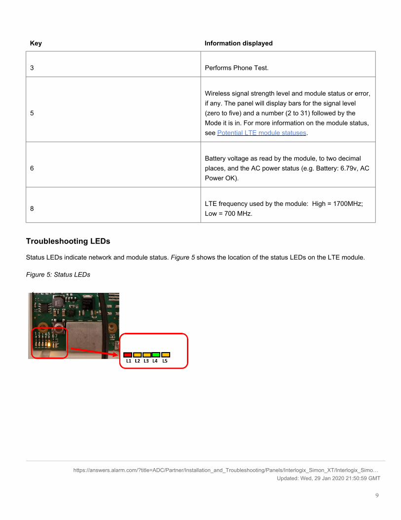
Troubleshooting LEDs
Status LEDs indicate network and module status. Figure 5 shows the location of the status LEDs on the LTE module.
Figure 5: Status LEDs
https://answers.alarm.com/?title=ADC/Partner/Installation_and_Troubleshooting/Panels/Interlogix_Simon_XT/Interlogix_Simo…Updated: Wed, 29 Jan 2020 21:50:59 GMT
9

LED Functions
LED Function
L1Error LED. Flashes one to eight times in an eight-secondinterval to indicate specific error. For more informationabout L1 errors, see LED L1 (red).
L2Panel Communication and Z-Wave status messages.Flashes every time the module communicates with thepanel and flashes in patterns to indicate Z-Wave status.
L3LTE Communication. Flashes every time the LTE signallevel is checked and when packets are exchanged withAlarm.com.
L4LTE Signal Level. Flashes zero to five times to indicatesignal strength, or toggles on/off slowly whencommunicating with Alarm.com servers.
L5Z-Wave Error LED. For more information about L5errors, see LED L5 (yellow).
LED L1 (red)
L1 flashes when there is an error. The number of flashes indicates the error number. If there are two or more errors atthe same time, the errors will flash one after the other. The LED will stay off for at least four seconds between errors.
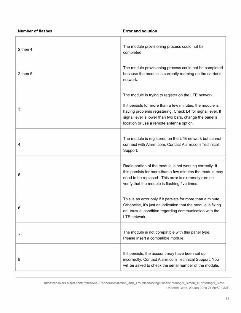
The following table shows the errors flashed on L1:
Number of flashes Error and solution
1
Module cannot communicate with the panel.
Perform a power cycle on the panel. If the error persistslift the module out of the panel and re-insert it. If the erroris still observed try a different module. Finally, if thatdoes not fix the problem try a different panel.
https://answers.alarm.com/?title=ADC/Partner/Installation_and_Troubleshooting/Panels/Interlogix_Simon_XT/Interlogix_Simo…Updated: Wed, 29 Jan 2020 21:50:59 GMT
10
Number of flashes Error and solution
2 then 4The module provisioning process could not becompleted.
2 then 5The module provisioning process could not be completedbecause the module is currently roaming on the carrier’snetwork.
3
The module is trying to register on the LTE network.
If it persists for more than a few minutes, the module ishaving problems registering. Check L4 for signal level. Ifsignal level is lower than two bars, change the panel’slocation or use a remote antenna option.
4The module is registered on the LTE network but cannotconnect with Alarm.com. Contact Alarm.com TechnicalSupport.
5
Radio portion of the module is not working correctly. Ifthis persists for more than a few minutes the module mayneed to be replaced. This error is extremely rare soverify that the module is flashing five times.
6
This is an error only if it persists for more than a minute.Otherwise, it’s just an indication that the module is fixingan unusual condition regarding communication with theLTE network.
7The module is not compatible with this panel type.Please insert a compatible module.
8If it persists, the account may have been set upincorrectly. Contact Alarm.com Technical Support. Youwill be asked to check the serial number of the module.
https://answers.alarm.com/?title=ADC/Partner/Installation_and_Troubleshooting/Panels/Interlogix_Simon_XT/Interlogix_Simo…Updated: Wed, 29 Jan 2020 21:50:59 GMT
11

LED L2 (yellow)
L2 flashes with every communication between the module and the panel. Normal pattern calls for a series of quickflashes every two seconds in Idle Mode or four seconds in PowerSave Mode. It also occasionally flashes in patterns toindicate Z-Wave status.
The following table shows the Z-wave LED status indicators on L2:
Flashes Device status or error Description
4-blinkAdd Mode (lasts 120 seconds or untila device is added).
A device can be added to the localZ-Wave network. Devices cannot beadded to a network if they arealready a part of a network.
2-blinkDelete Mode (lasts 120 seconds oruntil a device is deleted).
A device can be deleted from a Z-Wave network. A device can only bein one network at a time, and mustreceive a delete command before itcan be learned into a new network.
SolidSuccessful add node/remove node/replication (lasts 60 seconds).
After receiving this signal leave alldevices by the LTE module forone minute. Locks must be left nextto the module for four minutes.
Solid with one blinkAdd node attempt failed becausenode already in network (lasts 60seconds).
Device you attempted to add to anetwork is already in a network, andmust be deleted before it can join anew network.
LED L3 (yellow)
L3 flashes with every communication between the module and its radio unit in Idle Mode, and with every communicationwith Alarm.com in Connected Mode. In PowerSave Mode, this LED flashes in unison with LED 2.
LED L4 (green)
L4 indicates the LTE signal level as a number of flashes (zero to five bars). The number of bars may not correspond tothe bars shown on your cell phone. A level of five bars is obtained only in the strongest signal conditions.
https://answers.alarm.com/?title=ADC/Partner/Installation_and_Troubleshooting/Panels/Interlogix_Simon_XT/Interlogix_Simo…Updated: Wed, 29 Jan 2020 21:50:59 GMT
12

Signal level is updated every ten seconds if it fluctuates, or every 30 seconds if it is fairly stable.
If L4 is not flashing it indicates one of the following states:
• The module is in PowerSave Mode.• The module just powered up.• There is no LTE coverage in the area. The recommendation is a steady signal level of two or higher for proper
operation of the module.
In Connected Mode, the LED toggles on and off.
LED L5 (yellow)
L5 indicates Z-Wave errors.
The following table shows the possible Z-Wave errors:
Flashes Device or error status Description
2-blinkNo other nodes are in the network(lasts until a device is added to thenetwork).
No devices have been added thatcan be controlled by the LTE moduleyet.
5-blink Learn mode error (lasts 60 seconds).The device was not successfullyadded to the Z-Wave network.
6-blinkNo Home ID present (lasts until themodule connects to Alarm.com andis configured).
When the LTE module first connectsto Alarm.com it is configured with anecessary unique network ID.
Various module states (modes)
There are three module states, or modes, as described below:
Idle Mode
AC power is OK and the module is not currently talking to Alarm.com.
L1 - Flashes errors, if any.
L2 - Communication with panel.
L3 - Communication with radio unit.
https://answers.alarm.com/?title=ADC/Partner/Installation_and_Troubleshooting/Panels/Interlogix_Simon_XT/Interlogix_Simo…Updated: Wed, 29 Jan 2020 21:50:59 GMT
13

L4 - Signal level (zero to 5 bars).
L5 – Flashes errors, if any.
PowerSave Mode
The module just powered up, AC power is down, or AC power was recently restored and the battery is recharging. Themodule is fully functional and will go into Connected Mode as soon as a signal needs to be sent. Press and hold [5] for10 seconds to switch the module into Idle Mode and update the signal level reading. The system will go into Idle Modeevery two hours to check for any incoming messages.
L1 - Inactive.
L2 - Communication with panel.
L3 - Same flashing pattern as L2.
L4 - Inactive.
L5 - Inactive
Connected Mode
The module is currently talking to Alarm.com. The module stays in Connected Mode for at least four minutes afterreporting an event to Alarm.com, unless [5] is pressed and held for 10 seconds, which will cause the module to go backto Idle Mode.
L1 - Flashes errors, if any.
L2 - Communication with panel.
L3 - Communication with Alarm.com.
L4 - Alternates two seconds on, then two seconds off.
L5 - Inactive.
Sleep Mode
The panel is not connected to AC power, or there is an AC power failure, and the battery level is low. The module willconnect to Alarm.com to send a signal, but will otherwise draw almost no power.
Note: If the LTE module is powered down for a short period of time, buffered messages from Alarm.com may bereceived when module power is restored.
https://answers.alarm.com/?title=ADC/Partner/Installation_and_Troubleshooting/Panels/Interlogix_Simon_XT/Interlogix_Simo…Updated: Wed, 29 Jan 2020 21:50:59 GMT
14

Built-In radios
Important: Newer modules may have Z-Wave and Image Sensor radios built-in already. A daughterboard will not beneeded if the radio is built-in.
To verify which radios are built-in:
1. Log into the Partner Portal.2. Find the customer account.3. In Panel Information on the Customer Info page, click Alarm.com Serial #.4. In Modem Information, the Built-In Radios row will list which radios are built into the module.
Improving wireless signal strength
Guidelines for optimal wireless signal strength:
• Install the module above ground level, as high up as possible within the structure.• Install the module near or adjacent to an outside-facing wall of the structure.• Do not install the module inside a metal structure or close to large metal objects or ducts.• Make sure to follow the antenna positioning guidelines that are included with the antenna. Certain antennas must
be oriented a specific way in order to receive signals.• Upgrade the antenna. If using the 1/4 wave antenna included with the LTE module, upgrade to a remote cable
antenna. Contact Alarm.com technical support for antenna options.
As you make changes to the module location or antenna to improve signal strength, request updated signal readings toverify changes. To request an updated reading, press and hold [5] for 10 seconds on the XT or press Refresh in theModule Status menu on the XTi.
Note: On the XT 1.2 panel, some of the functionality found in the Interactive menus can be accessed using special keypresses.
Simon XT 1.3 and up interactive services menu:
To access the interactive services menus:
1. Enter the System Programming menu.2. Enter the installer code and press [OK].3. Press [OK] on Interactive Services.
https://answers.alarm.com/?title=ADC/Partner/Installation_and_Troubleshooting/Panels/Interlogix_Simon_XT/Interlogix_Simo…Updated: Wed, 29 Jan 2020 21:50:59 GMT
15

Menu Description
System Programming + Installer CodeScroll down to System Programming, enter the InstallerCode and press OK
- Interactive Services Scroll up to Interactive Services and press OK
-- LTE Module StatusScroll down through the various LTE module informationscreens
--- RadioSignal level, connection status, roaming status, anderrors (if any)
--- LTE Freq. LTE frequency used by the module.
--- LTE Band By default the module will choose the best LTE band.
--- Battery Current battery voltage and AC power status
--- SNModule serial number. Needed to create or troubleshootan Alarm.com account.
--- SIM cardIMSI number. Sometimes needed to troubleshoot anaccount
--- VersionLTE module firmware version and sub-version. Example:4183a, where 4 = XT, 183 = module firmware version, a= subversion (the label on the module will say X183)
-- Z-Wave Setup2
This menu is used to add, remove, and troubleshoot Z-Wave devices and networks. To control Z-Wave devicesvia the Alarm.com website and smart phone apps, youwill also need to enable Z-Wave services on the account.
https://answers.alarm.com/?title=ADC/Partner/Installation_and_Troubleshooting/Panels/Interlogix_Simon_XT/Interlogix_Simo…Updated: Wed, 29 Jan 2020 21:50:59 GMT
16

Menu Description
--- Number of Z-Wave Devices2 The total number of Z-Wave devices currently known tothe LTE module.
--- Add Z-Wave Device2
Press OK to enter Z-Wave Add Mode. Make sure thedevice you are trying to add is powered up and within 3to 6 feet of the Simon XT or XTi panel. Refer to themanufacturer’s instructions for button presses required toenroll device.
--- Remove Z-Wave Device2
Press “OK” to remove an existing Z-Wave device, or to“reset” a Z-Wave device that was previously learned intoa different Z-Wave network. Previously enrolled devicesmust be reset before they can be enrolled into themodule.
--- Z-Wave Home ID2
Press “OK” to query the Z-Wave network Home ID. If theID is 0, verify that the module has communicated withAlarm.com and that the Alarm.com account is set up forZ-Wave.
-- Account CreationThis menu is available only to installers who have theirown Alarm.com account creation system. You must entera Technician ID and a Lead ID in order to use this menu.
--Image Sensor Setup1
An Image Sensor daughterboard is required to enableImage Sensor capabilities on the module. The ImageSensor daughterboard comes built into AT&T LTEmodules.
--- Learn Image Sensor1Press “OK” to enter Add Mode. Enroll the Image Sensorby inserting batteries or resetting.
--- Delete Image Sensor1Press “OK” and scroll to the Image Sensor to delete.Press “OK” to delete.
https://answers.alarm.com/?title=ADC/Partner/Installation_and_Troubleshooting/Panels/Interlogix_Simon_XT/Interlogix_Simo…Updated: Wed, 29 Jan 2020 21:50:59 GMT
17

Menu Description
---Image Sensor Settings1 Press “OK” and scroll to the Image Sensor of interest.Press “OK”.
----Image Sensor #[x]1[x] is the sensor ID. Press “OK” to view information onthis Image Sensor.
-----[Power Information]1Gives information on the Image Sensor’s battery leveland power status.
-----Signal1The signal strength of the communication between theImage Sensor and the Image Sensor daughterboard.
-----Test PIR1 Press “OK” to put the Image Sensor in PIR Test Mode.
-----PIR Sensitivity1 Press “OK” to view current selection. Scroll down to viewavailable sensitivity levels. Press “OK” to select.
-- Dealer Logo Update
This menu is used to upload a Dealer logo to the two-way talking touchscreen (2WTTS). (Only available fordealers who have set up this feature with Alarm.com.)Press “OK”. If a logo is NOT available for upload to the2WTTS, you will see “Logo update not available”. If alogo is available, you will be asked to wait until thepanel’s LEDs start flashing, then wait until the panel’sLEDs stop flashing – at which time the logo should showon the 2WTTS.
System Test + Installer CodeScroll down to System Test, enter the Installer Code andpress OK
- Interactive Services Scroll up to Interactive Services and press OK
https://answers.alarm.com/?title=ADC/Partner/Installation_and_Troubleshooting/Panels/Interlogix_Simon_XT/Interlogix_Simo…Updated: Wed, 29 Jan 2020 21:50:59 GMT
18

Menu Description
-- Sensor Reporting Test
This menu is used to automate the process of confirmingthat all sensors report correctly to the Central Station. Itwill put the account on test and request the list ofsensors that did not report correctly. It is available only toinstallers who have integrated their sensor testingprocess with the Central Station and with Alarm.com
-- AVM/LTE Test
This menu is used to automate the process of testingAVM over the LTE link. It is available only to installerswho have integrated their wireless AVM testing processwith the Central Station and with Alarm.com
-- LTE Module Status See Installer Programming section above.
System Test + Master CodeScroll down to System Test, enter the Master Code andpress OK
- Interactive Services Scroll up to Interactive Services and press OK
-- LTE Module Status See Installer Programming section above.
-- Z-Wave Setup See Installer Programming section above.
-- Thermostat SettingsThis menu is used to troubleshoot the interactionbetween Z-Wave thermostats and the two-way wirelesstalking touch screen (2WTTS).
--- Thermostat 1, 2, 3 Select the thermostat and press OK.
https://answers.alarm.com/?title=ADC/Partner/Installation_and_Troubleshooting/Panels/Interlogix_Simon_XT/Interlogix_Simo…Updated: Wed, 29 Jan 2020 21:50:59 GMT
19

Menu Description
---- Node ID
The Z-Wave node id of the Z-Wave thermostat. If 0, thenthe Z-Wave thermostat has not been found. You mayneed to troubleshoot the Z-Wave network via the Z-WaveSetup menu. Press “OK” to have the module try to findthe thermostat again.
---- Mode The Z-Wave thermostat’s current mode (Off, Heat, Cool)
---- SetpointsThe current heating and cooling setpoints of the Z-Wavethermostat. These are the temperature thresholds thatdetermine when the heating or cooling unit will turn on.
---- Fan The current fan mode (Auto, On)
---- Schedules
Shows whether the thermostat is running on a schedule(On), or is using a fixed setpoint. Note that thesethermostat schedules must be set from the Alarm.comwebsite. Some Z-Wave thermostats allow settingschedules directly at the thermostat. These built-inschedules cannot be set or controlled via the website orvia the touch screen (2WTTS).
---- Update 2WTTS
Press OK to force an update of the thermostatinformation shown on the touch screen (2WTTS). Notethat these updates may take several minutes tocomplete. To speed up the process, go into SystemProgramming. This puts the panel in high-speedcommunication mode with the touch screen.
---- Remove From 2WTTSTo remove the association between the Z-Wavethermostat and the touch screen (2WTTS). This will hidethe Thermostat page on the 2WTTS.
https://answers.alarm.com/?title=ADC/Partner/Installation_and_Troubleshooting/Panels/Interlogix_Simon_XT/Interlogix_Simo…Updated: Wed, 29 Jan 2020 21:50:59 GMT
20

Menu Description
---- Last Temp. Read
For troubleshooting only. Shows how many unsuccessfulattempts were made by the LTE module at trying tocommunicate with the Z-Wave thermostat. A low numberof 0 or 1 is normal.
-- Request Weather UpdatePress OK if the weather forecast is not showing on thetouch screen (2WTTS).
[1] An Image Sensor daughterboard is required to enable Image Sensor functionality. All AT&T LTE modules include abuilt-in Image Sensor daughterboard. For general information on how to determine if the Image Sensor radio is built intothe module, see Built-In Radios. An interactive Alarm.com account with an Image Sensor service package is required forimage capabilities and features.[2] Refer to the emPowerTM installation instructions and guides on the Alarm.com Dealer Site for more information on Z-Wave enrollment and troubleshooting.
Table 6: XTi Interactive Services Menu
Menu Description
System Programming + Installer Code Scroll to Programming and enter the Installer Code.
- Interactive Services Select Interactive Services.
-- Module StatusProvides status and troubleshooting information for theLTE module.
-- Image Sensor1Enroll, troubleshoot and configure Image Sensors. Thismenu can also be used to retrieve images from theenrolled Image Sensors.
---Status1 View signal strength, PIR, battery and other informationabout each Image Sensor enrolled.
----Set PIR Sensitivity1 View and configure the PIR sensitivity for the ImageSensor.
https://answers.alarm.com/?title=ADC/Partner/Installation_and_Troubleshooting/Panels/Interlogix_Simon_XT/Interlogix_Simo…Updated: Wed, 29 Jan 2020 21:50:59 GMT
21

Menu Description
---Privacy1Remove all Image Sensor images currently stored on theXTi panel. (This does not affect image storage on theAlarm.com online account.)
--- Add1 Enroll the Image Sensor by inserting batteries orresetting.
---Image List1View list of images captured by the Image Sensor(s) onthe system and request to have specific images sent tothe panel for local viewing.
--- Test1Put the Image Sensor in PIR Test Mode (LED on sensorilluminates when activated) or request an “Installer Peek-In Now” to test image capture.
--- Delete1 Delete Image Sensors from the panel.
--Set Dealer LogoSend the dealer logo to the panel and touch screen.(Only available for dealers who have set up this featurewith Alarm.com.)
-- Weather Update
Request a Weather Update if the weather forecast is notshowing on the XTi touch screen. To speed up theprocess, stay in Programming. This keeps the panel inhigh-speed communication mode with the touch screens.
-- Z-Wave2
Used to add, remove, and troubleshoot Z-Wave devicesand networks. To control Z-Wave devices via theAlarm.com website and smart phone apps, you will alsoneed to enable Z-Wave services on the account.
https://answers.alarm.com/?title=ADC/Partner/Installation_and_Troubleshooting/Panels/Interlogix_Simon_XT/Interlogix_Simo…Updated: Wed, 29 Jan 2020 21:50:59 GMT
22

Menu Description
--- Add Device2
Add Z-Wave devices to the module’s network. Makesure the device you are trying to add is powered up andwithin 3 to 6 feet of the Simon XTi panel. Read themanufacturer’s instructions on what button to press onthe device to enroll it.
--- Remove Device2
Remove an existing Z-Wave device, or to “reset” a Z-Wave device that was previously learned into a differentZ-Wave network, before you can learn it into the LTEmodule.
---Update 2WTTS
Press Update 2WTTS to force an update of thethermostat, lights or locks information shown on thetouch screen (2WTTS). Note that these updates maytake several minutes to complete.
----ThermostatsView thermostat data and update/remove thermostatsfrom display on the panel and touch screens.
----LightsUpdate the lights list shown on the panel and touchscreens.
----LocksUpdate locks list shown on panel and touch screens andpair locks with their door contact sensor.
--- Advanced2 Provides additional functionality for advanced Z-Wavetroubleshooting and configuration.
---- Rediscovery2
Network rediscovery allows the system to determine themost efficient communication patch between Z-Wavedevices. (During this process the Z-Wave network isbusy and cannot respond to other commands.)
---- Replicate Mode2 Initiates replicate mode on the panel.
https://answers.alarm.com/?title=ADC/Partner/Installation_and_Troubleshooting/Panels/Interlogix_Simon_XT/Interlogix_Simo…Updated: Wed, 29 Jan 2020 21:50:59 GMT
23
Menu Description
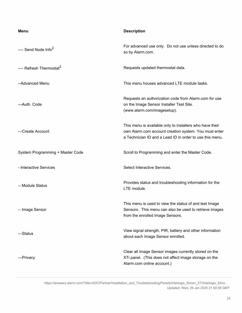
---- Send Node Info2 For advanced use only. Do not use unless directed to doso by Alarm.com.
---- Refresh Thermostat2 Requests updated thermostat data.
--Advanced Menu This menu houses advanced LTE module tasks.
---Auth. CodeRequests an authorization code from Alarm.com for useon the Image Sensor Installer Test Site.(www.alarm.com/imagesetup).
---Create AccountThis menu is available only to installers who have theirown Alarm.com account creation system. You must entera Technician ID and a Lead ID in order to use this menu.
System Programming + Master Code Scroll to Programming and enter the Master Code.
- Interactive Services Select Interactive Services.
-- Module StatusProvides status and troubleshooting information for theLTE module.
-- Image SensorThis menu is used to view the status of and test ImageSensors. This menu can also be used to retrieve imagesfrom the enrolled Image Sensors.
---StatusView signal strength, PIR, battery and other informationabout each Image Sensor enrolled.
---PrivacyClear all Image Sensor images currently stored on theXTi panel. (This does not affect image storage on theAlarm.com online account.)
https://answers.alarm.com/?title=ADC/Partner/Installation_and_Troubleshooting/Panels/Interlogix_Simon_XT/Interlogix_Simo…Updated: Wed, 29 Jan 2020 21:50:59 GMT
24

Menu Description
---Image ListView list of images captured by the Image Sensor(s) onthe system and request to have specific images sent tothe panel for local viewing.
--- TestPut the Image Sensor in PIR Test Mode (LED on sensorilluminates when activated) or request an “Installer Peek-In Now” to test image captures.
-- Weather Update
Request a Weather Update if the weather forecast is notshowing on the XTi touch screen. To speed up theprocess, stay in Programming. This keeps the panel inhigh-speed communication mode with the touch screens.
-- Z-Wave2
Used to add, remove, and troubleshoot Z-Wave devicesand networks. To control Z-Wave devices via theAlarm.com website and smart phone apps, you will alsoneed to enable Z-Wave services on the account.
--- Add Device2
Add Z-Wave devices to the module’s network. Makesure the device you are trying to add is powered up andwithin 3 to 6 feet of the Simon XTi panel. Read themanufacturer’s instructions on what button to press onthe device to enroll it.
--- Remove Device2
Remove an existing Z-Wave device, or to “reset” a Z-Wave device that was previously learned into a differentZ-Wave network, before you can learn it into the LTEmodule.
---Update 2WTTS
Press Update 2WTTS to force an update of thethermostat, lights or locks information shown on thetouch screen (2WTTS). Note that these updates maytake several minutes to complete.
https://answers.alarm.com/?title=ADC/Partner/Installation_and_Troubleshooting/Panels/Interlogix_Simon_XT/Interlogix_Simo…Updated: Wed, 29 Jan 2020 21:50:59 GMT
25

Menu Description
----ThermostatsView thermostat data and update/remove thermostatsfrom display on the panel and touch screens.
----LightsUpdate the lights list shown on the panel and touchscreens.
----LocksUpdate locks list shown on panel and touch screens andpair locks with their door contact sensor.
--- Advanced2 Provides additional functionality for advanced Z-Wavetroubleshooting and configuration.
---- Rediscovery2
Network rediscovery allows the system to determine themost efficient communication patch between Z-Wavedevices. (During this process the Z-Wave network isbusy and cannot respond to other commands.)
---- Replicate Mode2 Initiates replicate mode on the panel.
---- Send Node Info2 For advanced use only. Do not use unless directed to doso by Alarm.com.
---- Refresh Thermostat2 Requests updated thermostat data.
[1] An Image Sensor daughterboard is required to enable Image Sensor functionality. All AT&T LTE modules include abuilt-in Image Sensor daughterboard. For general information on how to determine if the Image Sensor radio is built intothe module, see Built-In Radios. An interactive Alarm.com account with an Image Sensor service package is required forimage capabilities and features.[2] Refer to the emPowerTM installation instructions and guides on the Alarm.com Dealer Site for more information on Z-Wave enrollment and troubleshooting.
Walking the customer through new user setup using the Customer Website:
Note: This only applies to customers on an interactive service package with an online account. This step is notrequired for customers that use the module for wireless signaling only.
https://answers.alarm.com/?title=ADC/Partner/Installation_and_Troubleshooting/Panels/Interlogix_Simon_XT/Interlogix_Simo…Updated: Wed, 29 Jan 2020 21:50:59 GMT
26

Before the customer can configure their website account, the Alarm.com account for that customer must be created onthe Partner Portal, and the LTE module associated with the account must be installed successfully.
To log in and access their account, the customer can go to www.alarm.com (or custom dealer website address) tocomplete the new subscriber setup procedure.
The customer needs the following:
• The website login and temporary password included on the Alarm.com Welcome Letter generated when theaccount was created by the Dealer.
• A list of their system sensors and touch screens with corresponding zone IDs.• At least one phone number and e-mail address where notifications can be sent.
Note: At least one sensor must be learned into the panel to complete the new subscriber setup. If not all sensors andtouch screens were learned in before powering up the module, an updated sensor list must be requested by performingan LTE phone test or requesting an updated equipment list from the Partner Portal.
Regulatory Information
Changes or modifications not expressly approved by Alarm.com can void the user’s authority to operate the equipment.
This equipment has been tested and found to comply with the limits for a Class B digital device, pursuant to part 15 ofthe FCC Rules. These limits are designed to provide reasonable protection against harmful interference in a residentialinstallation. This equipment generates, uses, and can radiate radio frequency energy and, if not installed and used inaccordance with the instructions, may cause harmful interference to radio communications.
However, there is no guarantee that interference will not occur in a particular installation. If this equipment does causeharmful interference to radio or television reception, which can be determined by turning the equipment off and on, theuser is encouraged to try to correct the interference by one or more of the following measures:
• Reorient or relocate the receiving antenna.• Increase the separation between the equipment and receiver.• Connect the equipment into an outlet on a circuit different form that which the receiver is connected• Consult the dealer or an experienced radio/TV technician for help.
Operation is subject to the following two conditions:
• This device may not cause interference.• This device must accept any interference, including interference that may cause undesired operation of the device.
This equipment complies with the FCC RF radiation exposure limits set forth for an uncontrolled environment. Thisequipment should be installed and operated with a minimum distance of 20 centimeters between the radiator and yourbody.
Listings - FCC ID: YL6-143470L, IC: 9111A-143470L
https://answers.alarm.com/?title=ADC/Partner/Installation_and_Troubleshooting/Panels/Interlogix_Simon_XT/Interlogix_Simo…Updated: Wed, 29 Jan 2020 21:50:59 GMT
27

Device contains - FCC ID: RI7LE910NAV2, IC: 5131A-LE910NAV2
Contact Information
For additional information and support on Alarm.com products and services, please visit www.alarm.com/dealer orcontact Alarm.com technical support at 1-866-834-0470.
https://answers.alarm.com/?title=ADC/Partner/Installation_and_Troubleshooting/Panels/Interlogix_Simon_XT/Interlogix_Simo…Updated: Wed, 29 Jan 2020 21:50:59 GMT
28