Embed Size (px)
Citation preview
Copyright Hari Balakrishnan, 2001-2005, and Nick Feamster, 2005. All rights reserved.Please do not redistribute without permission.
LECTURE 4Interdomain Internet Routing
The goal of this lecture is to explain how routing between different administrative do-mains works in the Internet. We discuss how Internet Service Providers (ISPs) ex-
change routing information (and packets) between each other, and how the way in whichthey buy service from and sell service to each other and their customers influences thetechnical research agenda of Internet routing in the real-world. We discuss the salient fea-tures of the Border Gateway Protocol, Version 4 (BGP4), the current interdomain routingprotocol in the Internet.
! 4.1 Autonomous Systems
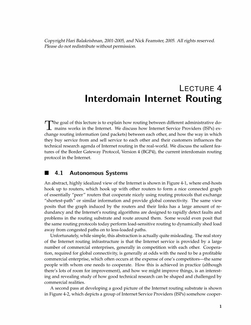
An abstract, highly idealized view of the Internet is shown in Figure 4-1, where end-hostshook up to routers, which hook up with other routers to form a nice connected graphof essentially “peer” routers that cooperate nicely using routing protocols that exchange“shortest-path” or similar information and provide global connectivity. The same viewposits that the graph induced by the routers and their links has a large amount of re-dundancy and the Internet’s routing algorithms are designed to rapidly detect faults andproblems in the routing substrate and route around them. Some would even posit thatthe same routing protocols today perform load-sensitive routing to dynamically shed loadaway from congested paths on to less-loaded paths.
Unfortunately, while simple, this abstraction is actually quite misleading. The real storyof the Internet routing infrastructure is that the Internet service is provided by a largenumber of commercial enterprises, generally in competition with each other. Coopera-tion, required for global connectivity, is generally at odds with the need to be a profitablecommercial enterprise, which often occurs at the expense of one’s competitors—the samepeople with whom one needs to cooperate. How this is achieved in practice (althoughthere’s lots of room for improvement), and how we might improve things, is an interest-ing and revealing study of how good technical research can be shaped and challenged bycommercial realities.
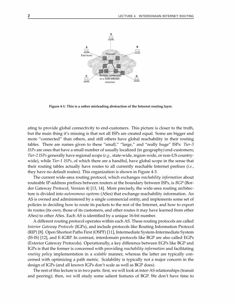
A second pass at developing a good picture of the Internet routing substrate is shownin Figure 4-2, which depicts a group of Internet Service Providers (ISPs) somehow cooper-
1
2 LECTURE 4. INTERDOMAIN INTERNET ROUTING
A B
C D
“Internet”End-hosts
Routers connectedin a fault-tolerant
structure
E
Figure 4-1: This is a rather misleading abstraction of the Internet routing layer.
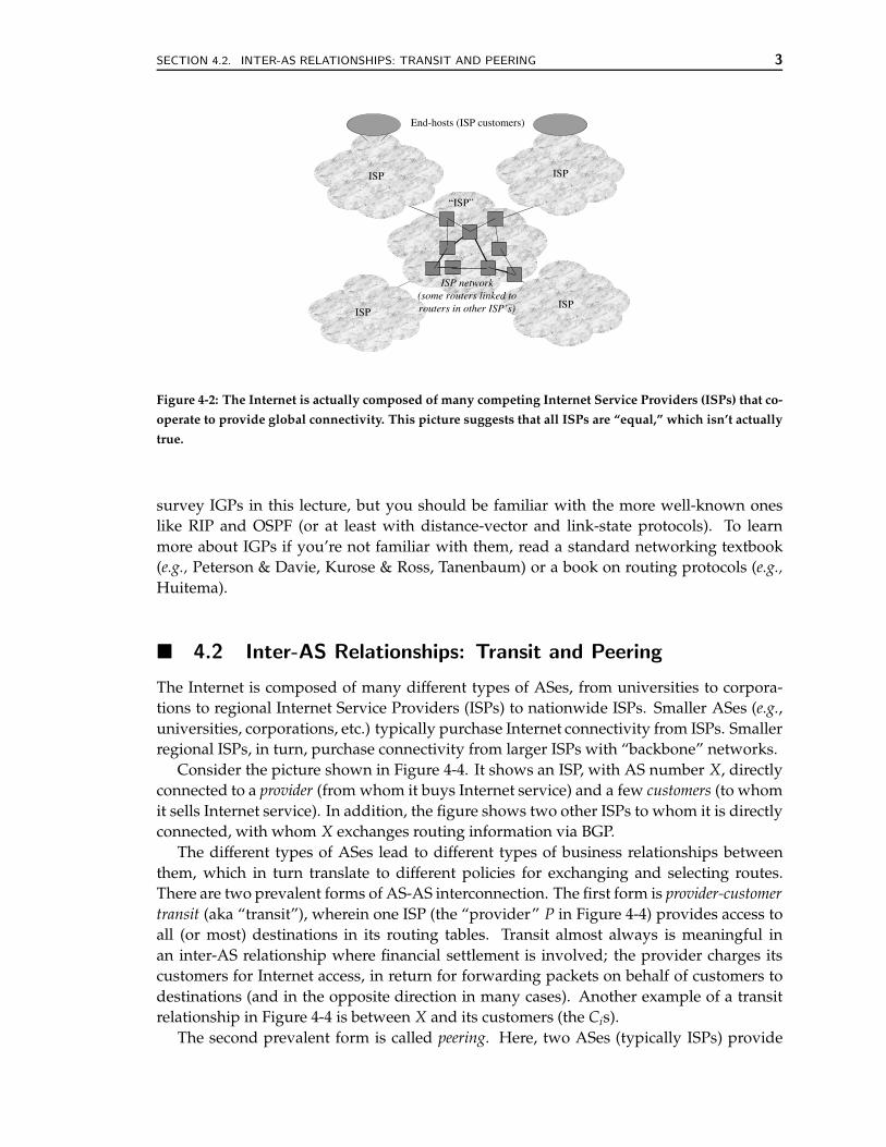
ating to provide global connectivity to end-customers. This picture is closer to the truth,but the main thing it’s missing is that not all ISPs are created equal. Some are bigger andmore “connected” than others, and still others have global reachability in their routingtables. There are names given to these “small,” “large,” and “really huge” ISPs: Tier-3ISPs are ones that have a small number of usually localized (in geography) end-customers;Tier-2 ISPs generally have regional scope (e.g., state-wide, region-wide, or non-US country-wide), while Tier-1 ISPs, of which there are a handful, have global scope in the sense thattheir routing tables actually have routes to all currently reachable Internet prefixes (i.e.,they have no default routes). This organization is shown in Figure 4-3.
The current wide-area routing protocol, which exchanges reachability information aboutrouteable IP-address prefixes between routers at the boundary between ISPs, is BGP (Bor-der Gateway Protocol, Version 4) [13, 14]. More precisely, the wide-area routing architec-ture is divided into autonomous systems (ASes) that exchange reachability information. AnAS is owned and administered by a single commercial entity, and implements some set ofpolicies in deciding how to route its packets to the rest of the Internet, and how to exportits routes (its own, those of its customers, and other routes it may have learned from otherASes) to other ASes. Each AS is identified by a unique 16-bit number.
A different routing protocol operates within each AS. These routing protocols are calledInterior Gateway Protocols (IGPs), and include protocols like Routing Information Protocol(RIP) [8]. Open Shortest Paths First (OSPF) [11], Intermediate System-Intermediate System(IS-IS) [12], and E-IGRP. In contrast, interdomain protocols like BGP are also called EGPs(Exterior Gateway Protocols). Operationally, a key difference between EGPs like BGP andIGPs is that the former is concerned with providing reachability information and facilitatingrouting policy implementation in a scalable manner, whereas the latter are typically con-cerned with optimizing a path metric. Scalability is typically not a major concern in thedesign of IGPs (and all known IGPs don’t scale as well as BGP does).
The rest of this lecture is in two parts: first, we will look at inter-AS relationships (transitand peering); then, we will study some salient features of BGP. We don’t have time to
SECTION 4.2. INTER-AS RELATIONSHIPS: TRANSIT AND PEERING 3
“ISP”
ISP network(some routers linked torouters in other ISP’s)
ISP
ISP
ISP
ISP
End-hosts (ISP customers)
Figure 4-2: The Internet is actually composed of many competing Internet Service Providers (ISPs) that co-
operate to provide global connectivity. This picture suggests that all ISPs are “equal,” which isn’t actually
true.
survey IGPs in this lecture, but you should be familiar with the more well-known oneslike RIP and OSPF (or at least with distance-vector and link-state protocols). To learnmore about IGPs if you’re not familiar with them, read a standard networking textbook(e.g., Peterson & Davie, Kurose & Ross, Tanenbaum) or a book on routing protocols (e.g.,Huitema).
! 4.2 Inter-AS Relationships: Transit and Peering
The Internet is composed of many different types of ASes, from universities to corpora-tions to regional Internet Service Providers (ISPs) to nationwide ISPs. Smaller ASes (e.g.,universities, corporations, etc.) typically purchase Internet connectivity from ISPs. Smallerregional ISPs, in turn, purchase connectivity from larger ISPs with “backbone” networks.
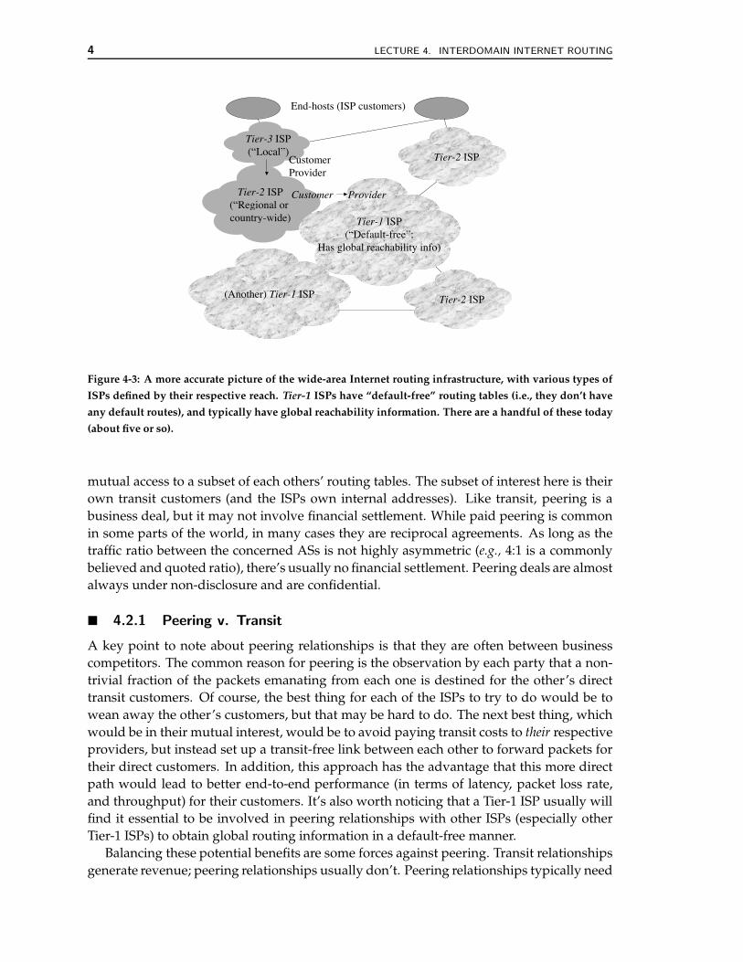
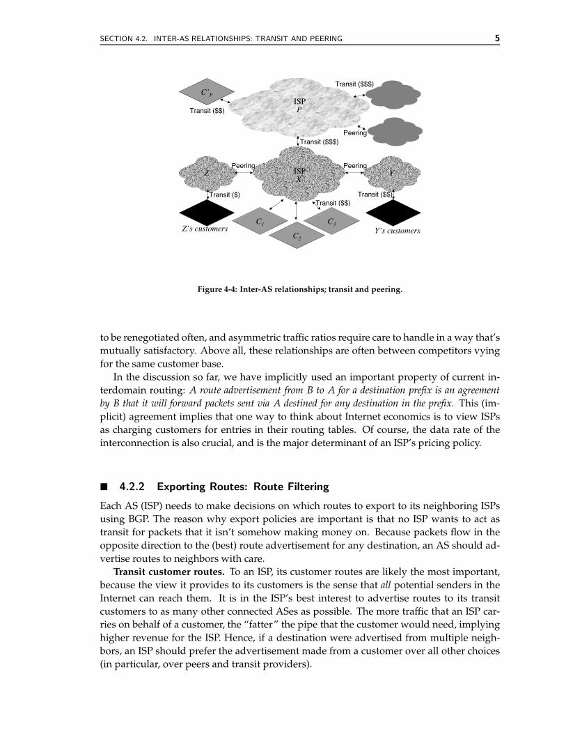
Consider the picture shown in Figure 4-4. It shows an ISP, with AS number X, directlyconnected to a provider (from whom it buys Internet service) and a few customers (to whomit sells Internet service). In addition, the figure shows two other ISPs to whom it is directlyconnected, with whom X exchanges routing information via BGP.
The different types of ASes lead to different types of business relationships betweenthem, which in turn translate to different policies for exchanging and selecting routes.There are two prevalent forms of AS-AS interconnection. The first form is provider-customertransit (aka “transit”), wherein one ISP (the “provider” P in Figure 4-4) provides access toall (or most) destinations in its routing tables. Transit almost always is meaningful inan inter-AS relationship where financial settlement is involved; the provider charges itscustomers for Internet access, in return for forwarding packets on behalf of customers todestinations (and in the opposite direction in many cases). Another example of a transitrelationship in Figure 4-4 is between X and its customers (the Cis).
The second prevalent form is called peering. Here, two ASes (typically ISPs) provide
4 LECTURE 4. INTERDOMAIN INTERNET ROUTING
Tier-1 ISP(“Default-free”;
Has global reachability info)
Tier-3 ISP(“Local”)
Tier-2 ISP(“Regional or country-wide)
Tier-2 ISP
End-hosts (ISP customers)
(Another) Tier-1 ISP
CustomerProvider
ProviderCustomer
Tier-2 ISP
Figure 4-3: A more accurate picture of the wide-area Internet routing infrastructure, with various types of
ISPs defined by their respective reach. Tier-1 ISPs have “default-free” routing tables (i.e., they don’t have
any default routes), and typically have global reachability information. There are a handful of these today
(about five or so).
mutual access to a subset of each others’ routing tables. The subset of interest here is theirown transit customers (and the ISPs own internal addresses). Like transit, peering is abusiness deal, but it may not involve financial settlement. While paid peering is commonin some parts of the world, in many cases they are reciprocal agreements. As long as thetraffic ratio between the concerned ASs is not highly asymmetric (e.g., 4:1 is a commonlybelieved and quoted ratio), there’s usually no financial settlement. Peering deals are almostalways under non-disclosure and are confidential.
! 4.2.1 Peering v. Transit
A key point to note about peering relationships is that they are often between businesscompetitors. The common reason for peering is the observation by each party that a non-trivial fraction of the packets emanating from each one is destined for the other’s directtransit customers. Of course, the best thing for each of the ISPs to try to do would be towean away the other’s customers, but that may be hard to do. The next best thing, whichwould be in their mutual interest, would be to avoid paying transit costs to their respectiveproviders, but instead set up a transit-free link between each other to forward packets fortheir direct customers. In addition, this approach has the advantage that this more directpath would lead to better end-to-end performance (in terms of latency, packet loss rate,and throughput) for their customers. It’s also worth noticing that a Tier-1 ISP usually willfind it essential to be involved in peering relationships with other ISPs (especially otherTier-1 ISPs) to obtain global routing information in a default-free manner.
Balancing these potential benefits are some forces against peering. Transit relationshipsgenerate revenue; peering relationships usually don’t. Peering relationships typically need
SECTION 4.2. INTER-AS RELATIONSHIPS: TRANSIT AND PEERING 5
C1
XISP YZ
C2
C3
Peering Peering
Transit ($$$)
Transit ($$)Transit ($) Transit ($$)
Z’s customers Y’s customers
P
C’P
Transit ($$)
Peering
Transit ($$$)
ISP
Figure 4-4: Inter-AS relationships; transit and peering.
to be renegotiated often, and asymmetric traffic ratios require care to handle in a way that’smutually satisfactory. Above all, these relationships are often between competitors vyingfor the same customer base.
In the discussion so far, we have implicitly used an important property of current in-terdomain routing: A route advertisement from B to A for a destination prefix is an agreementby B that it will forward packets sent via A destined for any destination in the prefix. This (im-plicit) agreement implies that one way to think about Internet economics is to view ISPsas charging customers for entries in their routing tables. Of course, the data rate of theinterconnection is also crucial, and is the major determinant of an ISP’s pricing policy.
! 4.2.2 Exporting Routes: Route Filtering
Each AS (ISP) needs to make decisions on which routes to export to its neighboring ISPsusing BGP. The reason why export policies are important is that no ISP wants to act astransit for packets that it isn’t somehow making money on. Because packets flow in theopposite direction to the (best) route advertisement for any destination, an AS should ad-vertise routes to neighbors with care.
Transit customer routes. To an ISP, its customer routes are likely the most important,because the view it provides to its customers is the sense that all potential senders in theInternet can reach them. It is in the ISP’s best interest to advertise routes to its transitcustomers to as many other connected ASes as possible. The more traffic that an ISP car-ries on behalf of a customer, the “fatter” the pipe that the customer would need, implyinghigher revenue for the ISP. Hence, if a destination were advertised from multiple neigh-bors, an ISP should prefer the advertisement made from a customer over all other choices(in particular, over peers and transit providers).
6 LECTURE 4. INTERDOMAIN INTERNET ROUTING
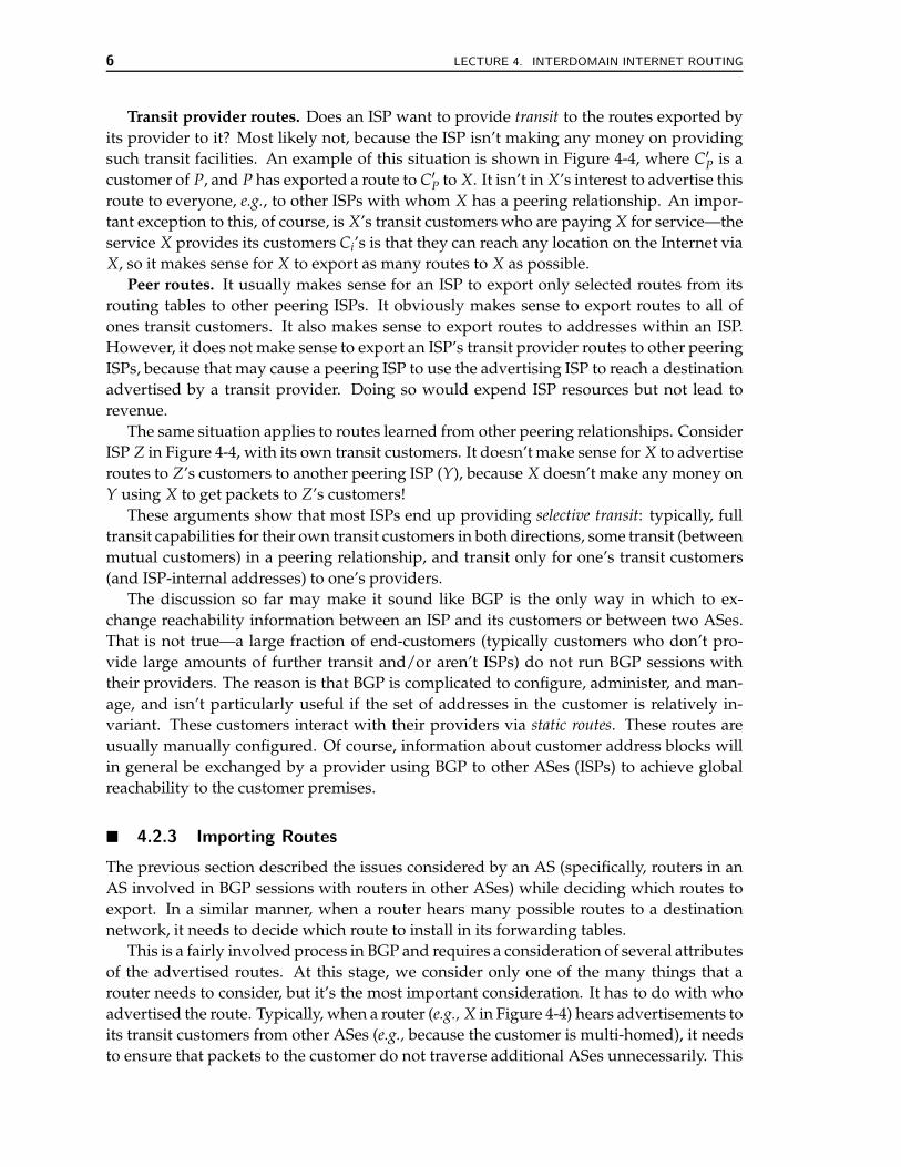
Transit provider routes. Does an ISP want to provide transit to the routes exported byits provider to it? Most likely not, because the ISP isn’t making any money on providingsuch transit facilities. An example of this situation is shown in Figure 4-4, where C′
P is acustomer of P, and P has exported a route to C′
P to X. It isn’t in X’s interest to advertise thisroute to everyone, e.g., to other ISPs with whom X has a peering relationship. An impor-tant exception to this, of course, is X’s transit customers who are paying X for service—theservice X provides its customers Ci’s is that they can reach any location on the Internet viaX, so it makes sense for X to export as many routes to X as possible.
Peer routes. It usually makes sense for an ISP to export only selected routes from itsrouting tables to other peering ISPs. It obviously makes sense to export routes to all ofones transit customers. It also makes sense to export routes to addresses within an ISP.However, it does not make sense to export an ISP’s transit provider routes to other peeringISPs, because that may cause a peering ISP to use the advertising ISP to reach a destinationadvertised by a transit provider. Doing so would expend ISP resources but not lead torevenue.
The same situation applies to routes learned from other peering relationships. ConsiderISP Z in Figure 4-4, with its own transit customers. It doesn’t make sense for X to advertiseroutes to Z’s customers to another peering ISP (Y), because X doesn’t make any money onY using X to get packets to Z’s customers!
These arguments show that most ISPs end up providing selective transit: typically, fulltransit capabilities for their own transit customers in both directions, some transit (betweenmutual customers) in a peering relationship, and transit only for one’s transit customers(and ISP-internal addresses) to one’s providers.
The discussion so far may make it sound like BGP is the only way in which to ex-change reachability information between an ISP and its customers or between two ASes.That is not true—a large fraction of end-customers (typically customers who don’t pro-vide large amounts of further transit and/or aren’t ISPs) do not run BGP sessions withtheir providers. The reason is that BGP is complicated to configure, administer, and man-age, and isn’t particularly useful if the set of addresses in the customer is relatively in-variant. These customers interact with their providers via static routes. These routes areusually manually configured. Of course, information about customer address blocks willin general be exchanged by a provider using BGP to other ASes (ISPs) to achieve globalreachability to the customer premises.
! 4.2.3 Importing Routes
The previous section described the issues considered by an AS (specifically, routers in anAS involved in BGP sessions with routers in other ASes) while deciding which routes toexport. In a similar manner, when a router hears many possible routes to a destinationnetwork, it needs to decide which route to install in its forwarding tables.
This is a fairly involved process in BGP and requires a consideration of several attributesof the advertised routes. At this stage, we consider only one of the many things that arouter needs to consider, but it’s the most important consideration. It has to do with whoadvertised the route. Typically, when a router (e.g., X in Figure 4-4) hears advertisements toits transit customers from other ASes (e.g., because the customer is multi-homed), it needsto ensure that packets to the customer do not traverse additional ASes unnecessarily. This
SECTION 4.3. BGP 7
usually means that customer routes are prioritized over routes to the same network ad-vertised by providers or peers. Second, peer routes are likely more preferable to providerroutes, since the purpose of peering was to exchange reachability information about mu-tual transit customers. These two observations imply that typically routes are imported inthe following priority order:
customer > peer > provider
This rule (and many others like it) can be implemented in BGP using a special attributethat’s locally maintained by routers in an AS, called the LOCAL PREF attribute. The firstrule in route selection with BGP is to pick a route based on this attribute. It is only ifthis attribute is not set for a route, are other attributes of a route even considered. Note,however, that in practice most routes in most ASes are not selected using the LOCAL PREFattribute; other attributes like the length of the AS path tend to be quite common. Wediscuss these other route attributes and the details of the BGP route selection process, alsocalled the decision process, in the next section.
! 4.3 BGP
We now turn to how reachability information is exchanged using BGP, and how routingpolicies like the ones explained in the previous section can be expressed and enforced. Westart with a discussion of the main design goals in BGP and summarize the protocol. Mostof the complexity in wide-area routing is not in the protocol, but in how BGP routers areconfigured to implement policy, and in how routes learned from other ASes are dissemi-nated within an AS. The rest of the section discusses these issues.
! 4.3.1 Design Goals
The design of BGP, and its current version (4), was motivated by three important needs:
1. Scalability. The division of the Internet into ASes under independent administrationwas done while the backbone of the then Internet was under the administration of theNSFNet. An important requirement for BGP was to ensure that the Internet routinginfrastructure remained scalable as the number of connected networks increased.
2. Policy. The ability for each AS to implement and enforce various forms of routingpolicy was an important design goal. One of the consequences of this was the devel-opment of the BGP attribute structure for route announcements, and allowing routefiltering.
3. Cooperation under competitive circumstances. BGP was designed in large part tohandle the transition from the NSFNet to a situation where the “backbone” Inter-net infrastructure would no longer be run by a single administrative entity. Thisstructure implies that the routing protocol should allow ASes to make purely localdecisions on how to route packets, from among any set of choices.
In the old NSFNET, the backbone routers exchanged routing information over a treetopology, using a routing protocol called EGP. (While the modern use of the term EGP
8 LECTURE 4. INTERDOMAIN INTERNET ROUTING
is as a family of exterior gateway protocols, its use in the context of NSFNET refers tothe specific one used in that network.) Because the backbone routing information wasexchanged over a tree, the routing protocol was relatively simple. The evolution of theInternet from a singly administered backbone to its current commercial structure madethe NSFNET EGP obsolete and required a more sophisticated protocol.
! 4.3.2 The Protocol
As protocols go, the operation of BGP is quite straightforward. The basic operation ofBGP—the protocol state machine, the format of routing messages, and the propagation ofrouting updates—are all defined in the protocol standard [13]. BGP runs over TCP, on awell-known port (179). To start participating in a BGP session with another router, a routersends an OPEN message after establishing a TCP connection to it on the BGP port. Afterthe OPEN is completed, both routers exchange their tables of all active routes (of course,applying all applicable route filtering rules). This process may take several minutes tocomplete, especially on sessions that have a large number of active routes.
After this initialization, there are two main types of messages on the BGP session. First,BGP routers send route UPDATE messages sent on the session. These updates only sendany routing entries that have changed since the last update (or transmission of all activeroutes). There are two kinds of updates: announcements, which are changes to existingroutes or new routes, and withdrawals, which are messages that inform the receiver thatthe named routes no longer exist. A withdrawal usually happens when some previouslyannounced route can no longer be used (e.g., because of a failure or a change in policy).Because BGP uses TCP, which provides reliable and in-order delivery, routes do not needto be periodically announced, unless they change.
But, in the absence of periodic routing updates, how does a router know whether theneighbor at the other end of a session is still functioning properly? One possible solutionmight be for BGP to run over a transport protocol that implements its own “is the peeralive” message protocol. Such messages are also called “keepalive” messages. TCP, how-ever, does not implement a transport-layer “keepalive”, so BGP uses its own. Each BGPsession has a configurable keepalive timer, and the router guarantees that it will attemptto send at least one BGP message during that time. If there are no UPDATE messages, thenthe router sends the second type of message on the session: KEEPALIVE messages. Theabsence of a certain number BGP KEEPALIVE messages on a session causes the router toterminate that session. The number of missing messages depends on a configurable timescalled the hold timer; the specification recommends that the hold timer be at least as longas the keepalive timer duration negotiated on the session.
More details about the BGP state machine may be found in [2, 13].Unlike many IGP’s, BGP does not simply optimize any metrics like shortest-paths or
delays. Because its goals are to provide reachability information and enable routing poli-cies, its announcements do not simply announce some metric like hop-count. Rather, theyhave the following format:
IP pre f ix : Attributes
where for each announced IP prefix, one or more attributes are also announced. There area substantial number of standardized attributes in BGP, and we’ll look at some of them in

SECTION 4.3. BGP 9
R2
R1
Info about D
D
iBGP
eBGP
Figure 4-5: eBGP and iBGP.
more detail in the rest of this lecture.Recall that one BGP attribute has already been introduced, the LOCAL PREF attribute.
This attribute isn’t disseminated with route announcements, but is an important attributeused locally while selecting a route for a destination. When a route is advertised from aneighboring AS, the receiving BGP router consults its configuration and may set a LOCALPREF for this route.
! 4.3.3 Disseminating Routes within an AS: eBGP and iBGP
There are two types of BGP sessions: eBGP sessions are between BGP-speaking routers indifferent ASes, while iBGP sessions are between BGP routers in the same AS. They servedifferent purposes, but use exactly the same protocol.
eBGP is the “standard” mode in which BGP is used; after all BGP was designed toexchange network routing information between different ASes in the Internet. eBGP ses-sions are shown in Figure 4-5, where the BGP routers implement route filtering rules andexchange a subset of their routes with routers in other ASes.
In general, each AS will have more than one router that participates in eBGP sessionswith neighboring ASes. During this process, each router will obtain information aboutsome subset of all the prefixes that the entire AS knows about. Each such eBGP routermust disseminate routes to the external prefix to all the other routers in the AS. This dis-semination must be done with care to meet two important goals:
1. Loop-free forwarding. After the dissemination of eBGP learned routes, the resultingroutes (and the subsequent forwarding paths of packets sent along those routes)picked by all routers should be free of deflections and forwarding loops [4, 7].
2. Complete visibility. One of the goals of BGP is to allow each AS to be treated as a singlemonolithic entity. This means that the several eBGP-speaking routes in the AS mustexchange external route information so that they have a complete view of all externalroutes. For instance, consider Figure 4-5, and prefix D. Router R2 needs to know how
10 LECTURE 4. INTERDOMAIN INTERNET ROUTING
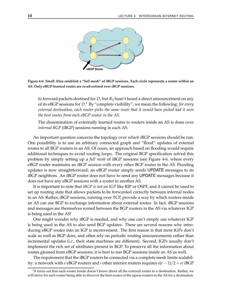
Figure 4-6: Small ASes establish a “full mesh” of iBGP sessions. Each circle represents a router within an
AS. Only eBGP-learned routes are re-advertised over iBGP sessions.
to forward packets destined for D, but R2 hasn’t heard a direct announcement on anyof its eBGP sessions for D.1 By “complete visibility”, we mean the following: for everyexternal destination, each router picks the same route that it would have picked had it seenthe best routes from each eBGP router in the AS.
The dissemination of externally learned routes to routers inside an AS is done overinternal BGP (iBGP) sessions running in each AS.
An important question concerns the topology over which iBGP sessions should be run.One possibility is to use an arbitrary connected graph and “flood” updates of externalroutes to all BGP routers in an AS. Of cours, an approach based on flooding would requireadditional techniques to avoid routing loops. The original BGP specification solved thisproblem by simply setting up a full mesh of iBGP sessions (see Figure 4-6, where everyeBGP router maintains an iBGP session with every other BGP router in the AS. Floodingupdates is now straightforward; an eBGP router simply sends UPDATE messages to itsiBGP neighbors. An iBGP router does not have to send any UPDATE messages because itdoes not have any eBGP sessions with a router in another AS.
It is important to note that iBGP is not an IGP like RIP or OSPF, and it cannot be used toset up routing state that allows packets to be forwarded correctly between internal nodesin an AS. Rather, iBGP sessions, running over TCP, provide a way by which routers insidean AS can use BGP to exchange information about external routes. In fact, iBGP sessionsand messages are themselves routed between the BGP routers in the AS via whatever IGPis being used in the AS!
One might wonder why iBGP is needed, and why one can’t simply use whatever IGPis being used in the AS to also send BGP updates. There are several reasons why intro-ducing eBGP routes into an IGP is inconvenient. The first reason is that most IGPs don’tscale as well as BGP does, and often rely on periodic routing announcements rather thanincremental updates (i.e., their state machines are different). Second, IGPs usually don’timplement the rich set of attributes present in BGP. To preserve all the information aboutroutes gleaned from eBGP sessions, it is best to run BGP sessions inside an AS as well.
The requirement that the iBGP routers be connected via a complete mesh limits scalabil-ity: a network with e eBGP routers and i other interior routers requires e(e− 1)/2 + ei iBGP
1It turns out that each router inside doesn’t know about all the external routes to a destination. Rather, wewill strive for each router being able to discover the best routes of the egress routers in the AS for a destination.
SECTION 4.3. BGP 11
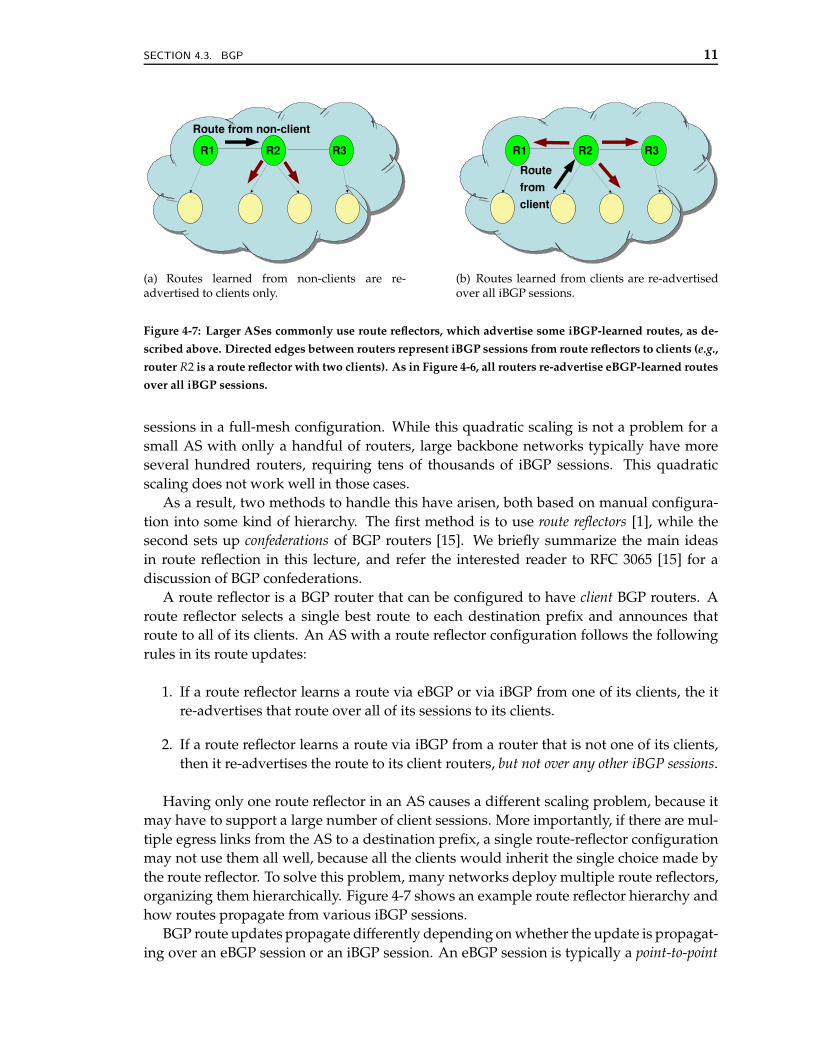
(a) Routes learned from non-clients are re-advertised to clients only.
(b) Routes learned from clients are re-advertisedover all iBGP sessions.
Figure 4-7: Larger ASes commonly use route reflectors, which advertise some iBGP-learned routes, as de-
scribed above. Directed edges between routers represent iBGP sessions from route reflectors to clients (e.g.,
router R2 is a route reflector with two clients). As in Figure 4-6, all routers re-advertise eBGP-learned routes
over all iBGP sessions.
sessions in a full-mesh configuration. While this quadratic scaling is not a problem for asmall AS with onlly a handful of routers, large backbone networks typically have moreseveral hundred routers, requiring tens of thousands of iBGP sessions. This quadraticscaling does not work well in those cases.
As a result, two methods to handle this have arisen, both based on manual configura-tion into some kind of hierarchy. The first method is to use route reflectors [1], while thesecond sets up confederations of BGP routers [15]. We briefly summarize the main ideasin route reflection in this lecture, and refer the interested reader to RFC 3065 [15] for adiscussion of BGP confederations.
A route reflector is a BGP router that can be configured to have client BGP routers. Aroute reflector selects a single best route to each destination prefix and announces thatroute to all of its clients. An AS with a route reflector configuration follows the followingrules in its route updates:
1. If a route reflector learns a route via eBGP or via iBGP from one of its clients, the itre-advertises that route over all of its sessions to its clients.
2. If a route reflector learns a route via iBGP from a router that is not one of its clients,then it re-advertises the route to its client routers, but not over any other iBGP sessions.
Having only one route reflector in an AS causes a different scaling problem, because itmay have to support a large number of client sessions. More importantly, if there are mul-tiple egress links from the AS to a destination prefix, a single route-reflector configurationmay not use them all well, because all the clients would inherit the single choice made bythe route reflector. To solve this problem, many networks deploy multiple route reflectors,organizing them hierarchically. Figure 4-7 shows an example route reflector hierarchy andhow routes propagate from various iBGP sessions.
BGP route updates propagate differently depending on whether the update is propagat-ing over an eBGP session or an iBGP session. An eBGP session is typically a point-to-point
12 LECTURE 4. INTERDOMAIN INTERNET ROUTING
session: that is, the IP addresses of the routers on either end of the session are directly con-nected with one another and are typically on the same local area network. There are someexceptions to this practice (i.e., “multi-hop eBGP” [5]), but directly connected eBGP ses-sions is normal operating procedure. In the case where an eBGP session is point-to-point,the next-hop attribute for the BGP route is guaranteed to be reachable, as is the other endof the point-to-point connection. A router will advertise a route over an eBGP sessionregardless of whether that route was originally learned via eBGP or iBGP.
On the other hand, an iBGP session may exist between two routers that are not directlyconnected, and it may be the case that the next-hop IP address for a route learned viaiBGP is more than one IP-level hop away. In fact, as the next-hop IP address of the routeis typically one of the border routers for the AS, this next hop may not even correspondto the router on the other end of the iBGP session, but may be several iBGP hops away.In iBGP, the routers thus rely on the AS’s internal routing protocol (i.e., its IGP) to both(1) establish connectivity between the two endpoints of the BGP session and (2) establishthe route to the next-hop IP address named in the route attribute.
Configuring an iBGP topology to correctly achieve loop-free forwarding and completevisibility is non-trivial. Incorrect iBGP topology configuration can create many types ofincorrect behavior, including persistent forwarding loops and oscillations [7]. Route re-flection causes problems with correctness because not all route reflector topologies satisfyvisibility (see [6] and references therein).
! 4.3.4 BGP Policy Expression: Filters and Rankings
BGP allows policy expression by allowing network operators to configure routers to manip-ulate route attributes when disseminating routes. Network operators can configure routersto perform the following policy-driven tasks:
1. Control how a router ranks candidate routes and select paths to destinations.
2. Control the “next hop” IP address for the advertised route to balance load.
3. “Tag” a route to control how the ranking and filtering functions on other routers treatthe route.
We’re now in a position to understand what the anatomy of a BGP route looks likeand how route announcements (and withdrawals) allow a router to compute a forwardingtable from all the routing information. This forwarding table typically has one chosenpath in the form of the egress interface (port) on the router, corresponding to the nextneighboring IP address, to send a packet destined for a prefix. Recall that each routerimplements the longest prefix match on each packet’s destination IP address.
! 4.3.5 Exchanging Reachability: NEXT HOP Attribute
A BGP route announcement has a set of attributes associated with each announced prefix.One of them is the NEXT HOP attribute, which gives the IP address of the router to sendthe packet to. As the announcement propagates across an AS boundary, the NEXT HOPfield is changed; typically, it gets changed to the IP address of the border router of the ASthe announcement came from.
SECTION 4.3. BGP 13
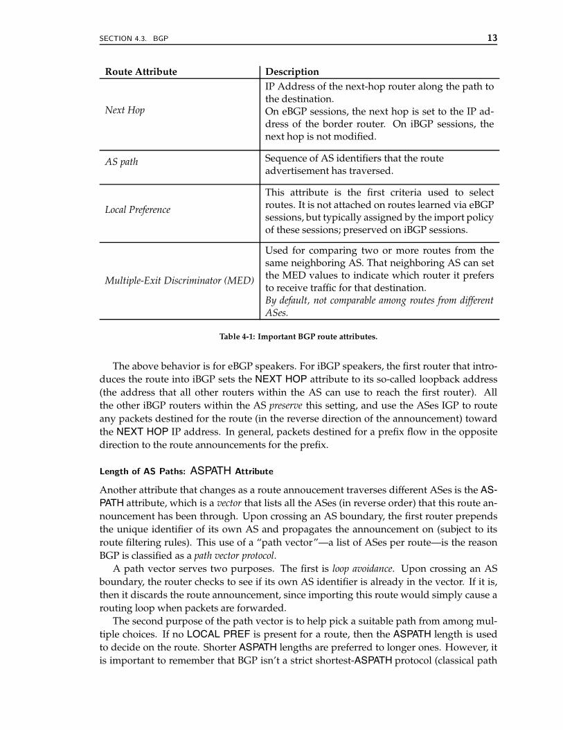
Route Attribute Description
Next Hop
IP Address of the next-hop router along the path tothe destination.On eBGP sessions, the next hop is set to the IP ad-dress of the border router. On iBGP sessions, thenext hop is not modified.
AS path Sequence of AS identifiers that the routeadvertisement has traversed.
Local Preference
This attribute is the first criteria used to selectroutes. It is not attached on routes learned via eBGPsessions, but typically assigned by the import policyof these sessions; preserved on iBGP sessions.
Multiple-Exit Discriminator (MED)
Used for comparing two or more routes from thesame neighboring AS. That neighboring AS can setthe MED values to indicate which router it prefersto receive traffic for that destination.By default, not comparable among routes from differentASes.
Table 4-1: Important BGP route attributes.
The above behavior is for eBGP speakers. For iBGP speakers, the first router that intro-duces the route into iBGP sets the NEXT HOP attribute to its so-called loopback address(the address that all other routers within the AS can use to reach the first router). Allthe other iBGP routers within the AS preserve this setting, and use the ASes IGP to routeany packets destined for the route (in the reverse direction of the announcement) towardthe NEXT HOP IP address. In general, packets destined for a prefix flow in the oppositedirection to the route announcements for the prefix.
Length of AS Paths: ASPATH Attribute
Another attribute that changes as a route annoucement traverses different ASes is the AS-PATH attribute, which is a vector that lists all the ASes (in reverse order) that this route an-nouncement has been through. Upon crossing an AS boundary, the first router prependsthe unique identifier of its own AS and propagates the announcement on (subject to itsroute filtering rules). This use of a “path vector”—a list of ASes per route—is the reasonBGP is classified as a path vector protocol.
A path vector serves two purposes. The first is loop avoidance. Upon crossing an ASboundary, the router checks to see if its own AS identifier is already in the vector. If it is,then it discards the route announcement, since importing this route would simply cause arouting loop when packets are forwarded.
The second purpose of the path vector is to help pick a suitable path from among mul-tiple choices. If no LOCAL PREF is present for a route, then the ASPATH length is usedto decide on the route. Shorter ASPATH lengths are preferred to longer ones. However, itis important to remember that BGP isn’t a strict shortest-ASPATH protocol (classical path
14 LECTURE 4. INTERDOMAIN INTERNET ROUTING
C
PDSF
NEXT HOP: SFMED = 100
NEXT HOP: BOSMED = 500
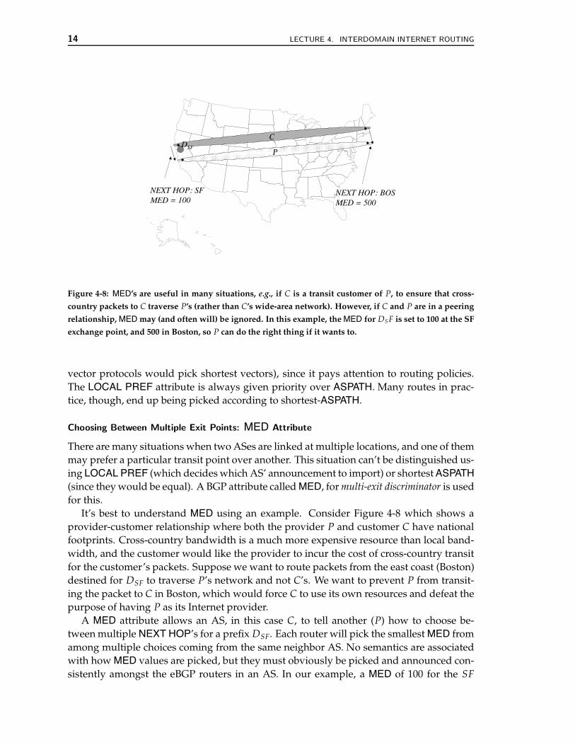
Figure 4-8: MED’s are useful in many situations, e.g., if C is a transit customer of P, to ensure that cross-
country packets to C traverse P’s (rather than C’s wide-area network). However, if C and P are in a peering
relationship, MED may (and often will) be ignored. In this example, the MED for DS F is set to 100 at the SF
exchange point, and 500 in Boston, so P can do the right thing if it wants to.
vector protocols would pick shortest vectors), since it pays attention to routing policies.The LOCAL PREF attribute is always given priority over ASPATH. Many routes in prac-tice, though, end up being picked according to shortest-ASPATH.
Choosing Between Multiple Exit Points: MED Attribute
There are many situations when two ASes are linked at multiple locations, and one of themmay prefer a particular transit point over another. This situation can’t be distinguished us-ing LOCAL PREF (which decides which AS’ announcement to import) or shortest ASPATH(since they would be equal). A BGP attribute called MED, for multi-exit discriminator is usedfor this.
It’s best to understand MED using an example. Consider Figure 4-8 which shows aprovider-customer relationship where both the provider P and customer C have nationalfootprints. Cross-country bandwidth is a much more expensive resource than local band-width, and the customer would like the provider to incur the cost of cross-country transitfor the customer’s packets. Suppose we want to route packets from the east coast (Boston)destined for DSF to traverse P’s network and not C’s. We want to prevent P from transit-ing the packet to C in Boston, which would force C to use its own resources and defeat thepurpose of having P as its Internet provider.
A MED attribute allows an AS, in this case C, to tell another (P) how to choose be-tween multiple NEXT HOP’s for a prefix DSF. Each router will pick the smallest MED fromamong multiple choices coming from the same neighbor AS. No semantics are associatedwith how MED values are picked, but they must obviously be picked and announced con-sistently amongst the eBGP routers in an AS. In our example, a MED of 100 for the SF
SECTION 4.3. BGP 15
NEXT HOP for prefix DSF and a MED of 500 for the BOS NEXT HOP for the same prefixaccomplishes the desired goal.
An important point to realize about MED’s is that they are usually ignored in AS-ASrelationships that don’t have some form of financial settlement (or explicit arrangement,in the absence of money). In particular, most peering arrangements ignore MED. Thisleads to a substantial amount of asymmetric routes in the wide-area Internet, as we’ll seein the next lecture. For instance, if P and C were in a peering relationship in Figure 4-8,cross-country packets going from C to P would traverse P’s wide-area network, whilecross-country packets from P to C would traverse C’s wide-area network. Both P and Cwould be in a hurry to get rid of the packet from their own network, a form of routingsometimes called hot-potato routing. In contrast, a financial arrangement would provide anincentive to honor MED’s and allow “cold-potato routing” to be enforced.
The case of large content hosts peering with tier-1 ISPs is an excellent real-world exam-ple of cold-potato routing. For instance, an ISP might peer with a content-hosting providerto obtain direct access to the latter’s customers (popular content-hosting sites), but does notwant the hosting provider to free-load on its backbone. This can be achieved by insistingthat its MEDs be honored.2
Putting It All Together
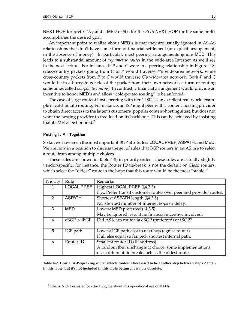
So far, we have seen the most important BGP attributes: LOCAL PREF, ASPATH, and MED.We are now in a position to discuss the set of rules that BGP routers in an AS use to selecta route from among multiple choices.
These rules are shown in Table 4-2, in priority order. These rules are actually slightlyvendor-specific; for instance, the Router ID tie-break is not the default on Cisco routers,which select the “oldest” route in the hope that this route would be the most “stable.”
Priority Rule Remarks1 LOCAL PREF Highest LOCAL PREF (§4.2.3).
E.g., Prefer transit customer routes over peer and provider routes.2 ASPATH Shortest ASPATH length (§4.3.5)
Not shortest number of Internet hops or delay.3 MED Lowest MED preferred (§4.3.5).
May be ignored, esp. if no financial incentive involved.4 eBGP > iBGP Did AS learn route via eBGP (preferred) or iBGP?
5 IGP path Lowest IGP path cost to next hop (egress router).If all else equal so far, pick shortest internal path.
6 Router ID Smallest router ID (IP address).A random (but unchanging) choice; some implementationsuse a different tie-break such as the oldest route.
Table 4-2: How a BGP-speaking router selects routes. There used to be another step between steps 2 and 3
in this table, but it’s not included in this table because it is now obsolete.
2I thank Nick Feamster for educating me about this operational use of MEDs.
16 LECTURE 4. INTERDOMAIN INTERNET ROUTING
Customer, C, AS=310.0.0.0/16
“Backup”
P110.0.0.0/12
P2
10.0.0.0/12 AND10.0.0.0/16
ASPATH {3 1}
10.0.0.0/16ASPATH {3 3 3 701}
AS 1 AS 701
Announce10.0.0.0/16
ASPATH {3 3 3}
Announce10.0.0.0/16ASPATH {3}
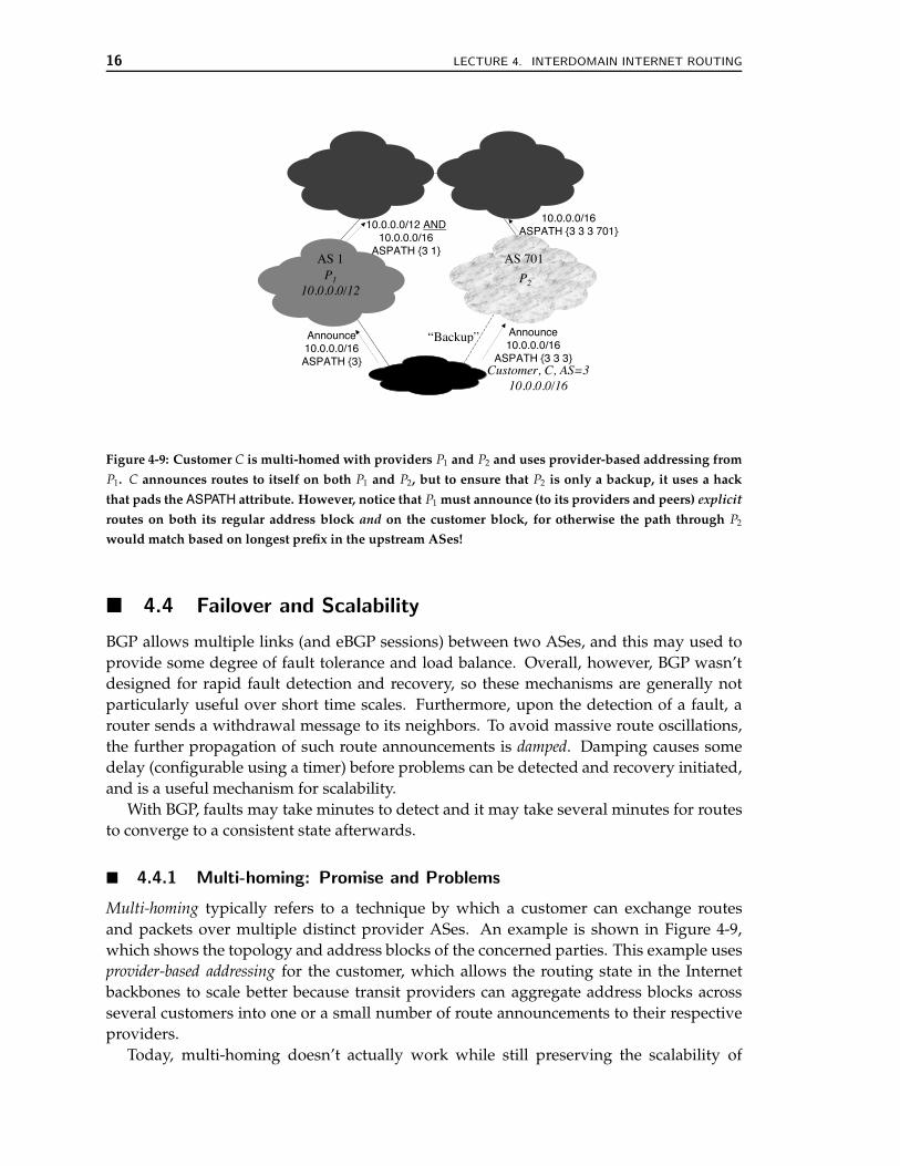
Figure 4-9: Customer C is multi-homed with providers P1 and P2 and uses provider-based addressing from
P1. C announces routes to itself on both P1 and P2, but to ensure that P2 is only a backup, it uses a hack
that pads the ASPATH attribute. However, notice that P1 must announce (to its providers and peers) explicit
routes on both its regular address block and on the customer block, for otherwise the path through P2
would match based on longest prefix in the upstream ASes!
! 4.4 Failover and Scalability
BGP allows multiple links (and eBGP sessions) between two ASes, and this may used toprovide some degree of fault tolerance and load balance. Overall, however, BGP wasn’tdesigned for rapid fault detection and recovery, so these mechanisms are generally notparticularly useful over short time scales. Furthermore, upon the detection of a fault, arouter sends a withdrawal message to its neighbors. To avoid massive route oscillations,the further propagation of such route announcements is damped. Damping causes somedelay (configurable using a timer) before problems can be detected and recovery initiated,and is a useful mechanism for scalability.
With BGP, faults may take minutes to detect and it may take several minutes for routesto converge to a consistent state afterwards.
! 4.4.1 Multi-homing: Promise and Problems
Multi-homing typically refers to a technique by which a customer can exchange routesand packets over multiple distinct provider ASes. An example is shown in Figure 4-9,which shows the topology and address blocks of the concerned parties. This example usesprovider-based addressing for the customer, which allows the routing state in the Internetbackbones to scale better because transit providers can aggregate address blocks acrossseveral customers into one or a small number of route announcements to their respectiveproviders.
Today, multi-homing doesn’t actually work while still preserving the scalability of
SECTION 4.4. FAILOVER AND SCALABILITY 17
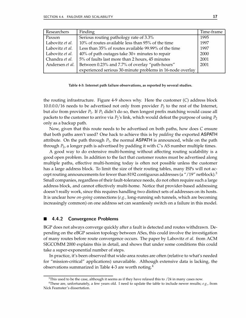
Researchers Finding Time-framePaxson Serious routing pathology rate of 3.3% 1995Labovitz et al. 10% of routes available less than 95% of the time 1997Labovitz et al. Less than 35% of routes available 99.99% of the time 1997Labovitz et al. 40% of path outages take 30+ minutes to repair 2000Chandra et al. 5% of faults last more than 2 hours, 45 minutes 2001Andersen et al. Between 0.23% and 7.7% of overlay “path-hours” 2001
experienced serious 30-minute problems in 16-node overlay
Table 4-3: Internet path failure observations, as reported by several studies.
the routing infrastructure. Figure 4-9 shows why. Here the customer (C) address block10.0.0.0/16 needs to be advertised not only from provider P2 to the rest of the Internet,but also from provider P1. If P1 didn’t do so, then longest prefix matching would cause allpackets to the customer to arrive via P2’s link, which would defeat the purpose of using P2
only as a backup path.Now, given that this route needs to be advertised on both paths, how does C ensure
that both paths aren’t used? One hack to achieve this is by padding the exported ASPATHattribute. On the path through P1, the normal ASPATH is announced, while on the paththrough P2, a longer path is advertised by padding it with C’s AS number multiple times.
A good way to do extensive multi-homing without affecting routing scalability is agood open problem. In addition to the fact that customer routes must be advertised alongmultiple paths, effective multi-homing today is often not possible unless the customerhas a large address block. To limit the size of their routing tables, many ISPs will not ac-cept routing announcements for fewer than 8192 contiguous addresses (a “/19” netblock).3
Small companies, regardless of their fault-tolerance needs, do not often require such a largeaddress block, and cannot effectively multi-home. Notice that provider-based addressingdoesn’t really work, since this requires handling two distinct sets of addresses on its hosts.It is unclear how on-going connections (e.g., long-running ssh tunnels, which are becomingincreasingly common) on one address set can seamlessly switch on a failure in this model.
! 4.4.2 Convergence Problems
BGP does not always converge quickly after a fault is detected and routes withdrawn. De-pending on the eBGP session topology between ASes, this could involve the investigationof many routes before route convergence occurs. The paper by Labovitz et al. from ACMSIGCOMM 2000 explains this in detail, and shows that under some conditions this couldtake a super-exponential number of steps.
In practice, it’s been observed that wide-area routes are often (relative to what’s neededfor “mission-critical” applications) unavailable. Although extensive data is lacking, theobservations summarized in Table 4-3 are worth noting.4
3This used to be the case, although it seems as if they have relaxed this to /24 in many cases now.4These are, unfortunately, a few years old. I need to update the table to include newer results; e.g., from
Nick Feamster’s dissertation.
18 REFERENCES
! 4.4.3 Correctness Problems
In the next lecture, we will study routing correctness and anomalies in depth. We discussthree key correctness properties: route validity, path visibility, and route safety, and showhow current interdomain routing violates all three properties some of the time. We alsodiscuss steps that could be taken to achieve correct routing in practice.
! 4.5 Summary
This lecture looked at issues in wide-area unicast Internet routing, focusing on real-worldissues. We first looked at inter-AS relationships and dealt with transit and peering issues.We then discussed many salient features and quirks of BGP, the prevalent wide-area rout-ing protocol today.
BGP is actually a rather simple protocol, but its operation in practice is extremely com-plex. Its complexity stems from configuration flexibility, which allows for a rich set ofattributes to be exchanged in route announcements. There are a number of open and in-teresting research problems in the area of wide-area routing, relating to policy, failover,scalability, configuration, and correctness. Despite much activity and impressive progressover the past few years, interdomain routing remains hard to understand and model.
The next lecture will discuss routing correctness and routing anomalies.
! Acknowledgments
This lecture has evolved over the past four years, thanks in large part to the wonderful col-laboration that Nick Feamster and I have had. A few subsections and two figures of thesenotes are edited from Nick’s dissertation. Thanks also to Jennifer Rexford and MythiliVutukuru for several discussions.
References
[1] T. Bates, R. Chandra, and E. Chen. BGP Route Reflection - An Alternative to Full MeshIBGP. Internet Engineering Task Force, Apr. 2000. RFC 2796. (Cited on page 11.)
[2] I. V. Beijnum. BGP. O’Reilly and Associates, Sept. 2002. (Cited on page 8.)
[3] D. Clark and D. Tennenhouse. Architectural Consideration for a New Generation ofProtocols. In Proc. ACM SIGCOMM, pages 200–208, Philadelphia, PA, Sept. 1990.(Cited on page 35.)
[4] R. Dube. A Comparison of Scaling Techniques for BGP. ACM ComputerCommunications Review, 29(3):44–46, July 1999. (Cited on page 9.)
[5] Cisco IOS IP Comand Reference, ebgp-multihop.http://www.cisco.com/en/US/products/sw/iosswrel/ps1835/productscommand reference chapter09186a00800ca79d.html, 2005. (Cited onpage 12.)
[6] N. Feamster and H. Balakrishnan. Detecting BGP Configuration Faults with StaticAnalysis. In Proc. 2nd Symposium on Networked Systems Design and Implementation(NSDI), pages 43–56, Boston, MA, May 2005. (Cited on page 12.)
[7] T. Griffin and G. Wilfong. On the Correctness of IBGP Configuration. In Proc. ACMSIGCOMM, pages 17–29, Pittsburgh, PA, Aug. 2002. (Cited on pages 9 and 12.)
[8] C. Hedrick. Routing Information Protocol. Internet Engineering Task Force, June 1988.RFC 1058. (Cited on page 2.)
[9] V. Jacobson. Congestion Avoidance and Control. In Proc. ACM SIGCOMM, pages314–329, Stanford, CA, Aug. 1988. (Cited on page 37.)
[10] P. Karn. MACA – A New Channel Access Method for Packet Radio. In Proc. 9thARRL Computer Networking Conference, 1990. (Cited on page 39.)
[11] J. Moy. OSPF Version 2, Mar. 1994. RFC 1583. (Cited on page 2.)
[12] D. Oran. OSI IS-IS intra-domain routing protocol. Internet Engineering Task Force, Feb.1990. RFC 1142. (Cited on page 2.)
19
20 REFERENCES
[13] Y. Rekhter and T. Li. A Border Gateway Protocol 4 (BGP-4). Internet Engineering TaskForce, Mar. 1995. RFC 1771. (Cited on pages 2 and 8.)
[14] Y. Rekhter, T. Li, and S. Hares. A Border Gateway Protocol 4 (BGP-4). InternetEngineering Task Force, Oct. 2004.http://www.ietf.org/internet-drafts/draft-ietf-idr-bgp4-26.txtWork in progress, expired April 2005. (Cited on page 2.)
[15] P. Traina, D. McPherson, and J. Scudder. Autonomous System Confederations for BGP.Internet Engineering Task Force, Feb. 2001. RFC 3065. (Cited on page 11.)