Embed Size (px)
Citation preview

ACM SIGGRAPH Motion in Games 2015
Interactive Detailed Cutting of Thin Sheets
Pierre-Luc Manteaux1 Wei-Lun Sun2 Francois Faure1 Marie-Paule Cani1 James F. O’Brien2
1University Grenoble-Alpes, CNRS (LJK) and Inria ∗ 2University of California, Berkeley †
Abstract
In this paper we propose a method for the interactive detailed cut-ting of deformable thin sheets. Our method builds on the abilityof frame-based simulation to solve for dynamics using very fewcontrol frames while embedding highly detailed geometry - here anadaptive mesh that accurately represents the cut boundaries. Oursolution relies on a non-manifold grid to compute shape functionsthat faithfully adapt to the topological changes occurring while cut-ting. New frames are dynamically inserted to describe new regions.We provide incremental mechanisms for updating simulation data,enabling us to achieve interactive rates. We illustrate our methodwith examples inspired by the traditional Kirigami artform.
CR Categories: I.3.7 [Computer Graphics]: Three-DimensionalGraphics and Realism—Animation;
Keywords: physics-based animation, cutting, thin sheets, interac-tive
1 Introduction
Over the last three decades, physics-based animation methods havebeen proposed to simulate a wide range of phenomena. Substantialprogress has been achieved in terms of efficiency and realism. Asa result, physics-based animation has found applications in film,games, craft, teaching, and training.
Combining interactive user actions and detailed convincing anima-tions is crucial for user experience in simulation and games. Un-fortunately, computational contraints limit the fidelity that can beachieved with physics-based animation in interactive simulations.Often, the simulated objects lack detail compared to the rest of thevirtual environment. Furthermore, operations that modify the struc-ture of the simulated objects, such as cutting, maybe incompatiblewith faster simulation methods. When not prohibited, the latter gen-erally exhibit strong limitations. Indeed, the level of sampling of aphysically-based model usually depends on geometric complexity.Detailed cuts result in an increase of the sampling which directlyimpacts the performance. In practice, the number of samples islimited to ensure real-time performance. This limitation quicklyprevents the user from applying detailed cuts.
In this work, we address the issue of enabling detailed cuts at in-teractive rates in thin sheets of deformable materials. Our methodis able to capture detailed cuts while using a relatively low numberof control nodes for the physically-based model. Our approach todecoupling the samplings of the physical geometric models, is touse a mesh-less simulation method called the frame-based model
∗pierre-luc.manteaux|francois.faure|[email protected]† sunweilunjwilson|[email protected]
From the proceedings of Motion in Games 2015.Permission to make digital or hard copies of all or part of this work for personal orclassroom use is granted without fee provided that copies are not made or distributedfor profit or commercial advantage and that copies bear this notice and the full citationon the first page. To copy otherwise, to republish, to post on servers or to redistributeto lists, requires prior specific permission and/or a fee.c© Copyright ACM 2015
(a) (b)
Figure 1: Progressive cutting of a spiral using only five con-trol frames (a). Simulating complex deformations resulting fromKirigami cutting (b).
[Gilles et al. 2011]. In this method, the deformation field inducedby animated frames is applied to the geometric model using skin-ning weights. As each frame can cover a large, detailed shapedregion of the geometric mesh, only a few of them are typically re-quired.
To achieve user-driven cuts in a frame-based simulation, we allowcuts to be performed on the underlying mesh. We build a non-manifold grid that keeps track of the mesh topology at the simula-tion level, and allows us to incrementally adapt the frames regionsof influence in order to represent the cut. Although remaining low,the number of frame node does increase during a cut. In particular,when a model is cut apart, at least one frame is needed to representeach disconnected component. Therefore, we detect crucial cuttingevents, enabling us to automatically insert new frames when andwhere they are needed. In order to reduce computations, we exploitthe locality of the ongoing cutting gesture to incrementally updateall the data used for the simulation.
Our contributions include (1) the building of a non-manifold gridto compute shape functions that faithfully represent the complextopology of the visual mesh while keeping a low number of con-trol nodes, (2) the dynamic re-sampling of new frames into discon-nected parts and (3) the incremental update of the simulation datathat were concerned by the cut.
Our method can be used to simulate a wide variety of objects, suchas stretchable cloth or pieces of paper. It features a very low num-ber of frame nodes, high resolution mesh embedding, numerousand detailed cuts. Performance ranges from interactive to offlinedepending on the desired accuracy and complexity of the cuts.
2 Related Work
Cutting and fracture are both fascinating behaviors which can besimulated separately. In fracture, stress measurements predict howthe material breaks. In cutting, the interaction with a tool define thecut path. For more details about cutting we refer the reader to therecent survey of Wu et al. [Wu et al. 2015]. Our review focuses onthe modeling of topological changes in deformable models.
A first possibility consists in using the same model for physicssimulation and visualization. Topological changes are then mostlymodeled by remeshing operations. Simple and fast remeshing tech-niques such as element deletion or element splitting were proposed.The latter was used in the first simulation of brittle and ductile mate-rials [O’Brien and Hodgins 1999], [O’Brien et al. 2002]. Methods
1
(a)
1
0(b)
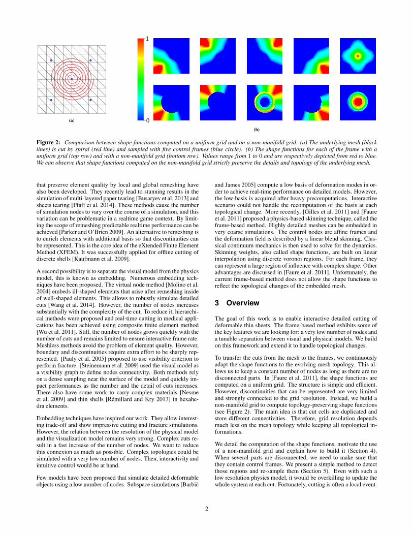
Figure 2: Comparison between shape functions computed on a uniform grid and on a non-manifold grid. (a) The underlying mesh (blacklines) is cut by spiral (red line) and sampled with five control frames (blue circle). (b) The shape functions for each of the frame with auniform grid (top row) and with a non-manifold grid (bottom row). Values range from 1 to 0 and are respectively depicted from red to blue.We can observe that shape functions computed on the non-manifold grid strictly preserve the details and topology of the underlying mesh.
that preserve element quality by local and global remeshing havealso been developed. They recently lead to stunning results in thesimulation of multi-layered paper tearing [Busaryev et al. 2013] andsheets tearing [Pfaff et al. 2014]. These methods cause the numberof simulation nodes to vary over the course of a simulation, and thisvariation can be problematic in a realtime game context. By limit-ing the scope of remeshing predictable realtime performance can beachieved [Parker and O’Brien 2009]. An alternative to remeshing isto enrich elements with additional basis so that discontinuities canbe represented. This is the core idea of the eXtended Finite ElementMethod (XFEM). It was successfully applied for offline cutting ofdiscrete shells [Kaufmann et al. 2009].
A second possibility is to separate the visual model from the physicsmodel, this is known as embedding. Numerous embedding tech-niques have been proposed. The virtual node method [Molino et al.2004] embeds ill-shaped elements that arise after remeshing insideof well-shaped elements. This allows to robustly simulate detailedcuts [Wang et al. 2014]. However, the number of nodes increasessubstantially with the complexity of the cut. To reduce it, hierarchi-cal methods were proposed and real-time cutting in medical appli-cations has been achieved using composite finite element method[Wu et al. 2011]. Still, the number of nodes grows quickly with thenumber of cuts and remains limited to ensure interactive frame rate.Meshless methods avoid the problem of element quality. However,boundary and discontinuities require extra effort to be sharply rep-resented. [Pauly et al. 2005] proposed to use visibility criterion toperform fracture. [Steinemann et al. 2009] used the visual model asa visibility graph to define nodes connectivity. Both methods relyon a dense sampling near the surface of the model and quickly im-pact performances as the number and the detail of cuts increases.There also have some work to carry complex materials [Nesmeet al. 2009] and thin shells [Remillard and Kry 2013] in hexahe-dra elements.
Embedding techniques have inspired our work. They allow interest-ing trade-off and show impressive cutting and fracture simulations.However, the relation between the resolution of the physical modeland the visualization model remains very strong. Complex cuts re-sult in a fast increase of the number of nodes. We want to reducethis connexion as much as possible. Complex topologies could besimulated with a very low number of nodes. Then, interactivity andintuitive control would be at hand.
Few models have been proposed that simulate detailed deformableobjects using a low number of nodes. Subspace simulations [Barbic
and James 2005] compute a low basis of deformation modes in or-der to achieve real-time performance on detailed models. However,the low-basis is acquired after heavy precomputations. Interactivescenario could not handle the recomputation of the basis at eachtopological change. More recently, [Gilles et al. 2011] and [Faureet al. 2011] proposed a physics-based skinning technique, called theframe-based method. Highly detailed meshes can be embedded invery coarse simulations. The control nodes are affine frames andthe deformation field is described by a linear blend skinning. Clas-sical continuum mechanics is then used to solve for the dynamics.Skinning weights, also called shape functions, are built on linearinterpolation using discrete voronoi regions. For each frame, theycan represent a large region of influence with complex shape. Otheradvantages are discussed in [Faure et al. 2011]. Unfortunately, thecurrent frame-based method does not allow the shape functions toreflect the topological changes of the embedded mesh.
3 Overview
The goal of this work is to enable interactive detailed cutting ofdeformable thin sheets. The frame-based method exhibits some ofthe key features we are looking for: a very low number of nodes anda tunable separation between visual and physical models. We buildon this framework and extend it to handle topological changes.
To transfer the cuts from the mesh to the frames, we continuouslyadapt the shape functions to the evolving mesh topology. This al-lows us to keep a constant number of nodes as long as there are nodisconnected parts. In [Faure et al. 2011], the shape functions arecomputed on a uniform grid. The structure is simple and efficient.However, discontinuities that can be represented are very limitedand strongly connected to the grid resolution. Instead, we build anon-manifold grid to compute topology-preserving shape functions(see Figure 2). The main idea is that cut cells are duplicated andstore different connectivities. Therefore, grid resolution dependsmuch less on the mesh topology while keeping all topological in-formations.
We detail the computation of the shape functions, motivate the useof a non-manifold grid and explain how to build it (Section 4).When several parts are disconnected, we need to make sure thatthey contain control frames. We present a simple method to detectthose regions and re-sample them (Section 5). Even with such alow resolution physics model, it would be overkilling to update thewhole system at each cut. Fortunately, cutting is often a local event.
2

(a)
VbVi
Ve
i2dmax
(b)
j
dj,Vb
dj,ij
dj,i
dj,Vb
(c)
Figure 3: Illustrations of Voronoi shape function computation. (a) Starting from samples (blue circles), we build a Voronoi diagram usingDijkstra’s shortest path algorithm. (b) Then, for each frame and its region Vi, we compute the maximum distance dmax to its Voronoiboundary Vb. We extend Vi to twice dmax which gives Ve. (c) Finally for each grid cell j in Ve we linearly interpolate using distance to theframe position and distance to Vb.
We leverage this fact and propose simple strategies to incrementallyupdate the different components of the simulation (Section 6). Weillustrate our method in different scenarios (Section 7) and discusslimitations and future work (Section 8). We summarize our simu-lation loop in Algorithm 1 and detail our remeshing algorithm inappendix A.
Algorithm 1 Simulation loop
for each time step doperform a frame-based simulation stepsplit the mesh along the cutembed the mesh in a non-manifold gridadd new frames if requiredadd new samples (collision, integration) if requiredcompute shape functions on the gridincrementally update the samples
end for
4 Adaptive shape functions
In this section, we first summarize how Voronoi shape functions aretraditionally computed. Then we detail why a non-manifold grid isnecessary, how to build it and how to use it to compute the shapefunctions on complex topology.
4.1 Voronoi shape function
Let wi(x) : Ω → R be the shape function for the i-th controlframe, where Ω represents the domain. Starting from the Voronoipartition V of the set of control frames, we can independently com-pute wi for each frame.
First, we compute the maximal distance dmax from the controlnode to its Voronoi boundary Vb. Then we extend its Voronoi re-gion Vi to twice dmax. This gives a new region Ve which describesthe final boundary of the shape function. Now, we can compute wi
inside Ve. We set wi to be 1 at the frame position, 0 at the othersand 0.5 on Vb. Finally, we linearly interpolate wi between Vb, theframe position and the boundary of Ve. We detail the interpolationin Algorithm 2 and in Figure 3.
In practice, Voronoi diagram is computed using Dijkstra’s shortestpath algorithm on a grid in order to preserve geodesic distances.For each frame, the shape function is computed on the whole grid.As the grid resolution can be quite coarse, this is particularly fast.Negative values are clamped and weights are normalized to form a
partition of unity. Then least-square approximation is performed toevaluate the shape function and its derivatives at specific position.
Algorithm 2 Shapefunction computation
1: procedure COMPUTE SHAPEFUNCTION2: for each frame i do3: Vi ← Voronoi region of i4: Vb ← boundary of Vi
5: dmax ← maximum distance to Vi boundary6: Ve ← extend Vi to 2.0× dmax
7: . dist(A,B) is the geodesic distance between A and B8: for each grid cell j in Ve do9: if j is inside Vi then
10: wi(j) = 0.5
(1 +
dist(j, Vb)
dist(j, Vb) + dist(j, i)
)11: else if j is inside Ve then
12: wi(j) = 0.5
(1− dist(j, Vb)
dist(j, i)− dist(j, Vb)
)13: end if14: end for15: end for16: end procedure
Voronoi shape functions were designed in order to respect keyproperties that are particularly useful for physics-based animation[Faure et al. 2011] . First, they respect the Kronecker property, i.ewi(x) = δi(x) where wi(x) is the shape function of node i, x isa spatial position and δi is Dirac function. Second, they form apartition of unity, i.e
∑i wi(x) = 1. Third, they are built to be
as linear as possible in order to produce uniform deformations. Fi-nally, they can easily be biased by material properties in order torepresent heterogeneous material.
4.2 Non-manifold grid
As mentionned above, in [Faure et al. 2011], shape functions arecomputed on a uniform grid using Dijktra’s shortest path algo-rithm to compute geodesic distance. Starting from a uniform gridwith a 8-neighbor connectivity, we could reflect topological changeby changing the connectivity of the cut cells. Then, when were-compute shape functions, the topology would automatically betaken into account as we use geodesic distance.
Unfortunately, this strategy is very limited for uniform grid andwould only work in simple cases. For instance, several cuts that in-tersect or that create disconnected components inside one cell could
3

(a) (b) (c)
Figure 4: Illustrations of different possibilities for a non-manifold cell with eight connectivity (a). In (b), the cell is simply cut into two cells.Each duplicate of the cut cell has a specific connectivity that represent the cut topology. In (c), multiple disconnected components can becontained inside one cell. The cell is duplicated four times. Three of the duplicates have no connectivity. However they can embed complexgeometry and then be simulated by adding new frames for each of the component. The fourth duplicate keeps its eight neighbors and remainsindependent from the three other.
not be represented. Even without cut, small gaps that lie inside onecell could not be correctly represented. Geodesic distances wouldbe false and the object would behave as if there were no cuts orgaps. Augmenting the resolution would not solve the problem. Wewould fight the same issue as previous methods. Our grid resolutionwould be highly dependent on the complexity of the topology andthe geometry of the object. It would directly impact performances.
We want each grid cell to be able to represent the connectivities ofthe different disconnected components that lie in the cell. To doso, each cut cell is duplicated as many times as it contains discon-nected parts. Each duplicate has a specific connectivity built fromthe material connectivity. This results in a data structure called non-manifold grid (see Figure 4).
Non-manifold grids are used by many other cutting methods toembed fine geometric details in coarse finite element simulations.However, we make a completely different use of it. Instead of du-plicating control nodes as the cells are cut, thereby increasing theirnumber and the computation time, we use the grid to adapt theshape functions to the evolving topology of the mesh. Most of thetime, the number of nodes can remain constant while representingdetailed geometry and multiple cuts.
There are several ways to compute this non-manifold grid. In ourmethod, we start by embedding the mesh in a uniform grid. Meshelements that overlap a grid cell are detected using intersectionstests and are assigned to it. Then, for each grid cell, we use a floodfill algorithm to detect the disconnected parts of the mesh. This in-forms about how many duplicates need to be created for the cell.Finally, for each duplicate we establish its connectivity by compar-ing its geometry with the geometry of the neighbor cells duplicates.We summarize our method in Algorithm 3 and illustrate the mainsteps in Figure 5.
5 Frame re-sampling
As long as no parts of the model are disconnected, our method al-lows to keep a constant number of control frames. However, whenparts are disconnected, we need to sample it with at least one framein order to simulate it.
We start by detecting empty regions i.e lists of connected cells thatare not influenced by any frame. This is done using a flood fill al-gorithm on the grid containing the shape functions values. Theseempty regions are then sampled using a farthest sampling algo-rithm. Finally, the samples are uniformly distributed by applyingseveral Lloyd relaxation steps. For now, the number of frames
Algorithm 3 Non-manifold grid building
1: procedure BUILD NON MANIFOLD GRID(grid G, mesh M )2: BUILD GRID GEOMETRY(G,M )3: DUPLICATE GRID CELL(G)4: BUILD GRID CONNECTIVITY(G)5: end procedure6:7: procedure BUILD GRID GEOMETRY(grid G, mesh M )8: for each cell i of G do9: Store overlapping element of M
10: end for11: end procedure12:13: procedure DUPLICATE GRID CELL(grid G, mesh M )14: for each cell i of G do15: C ← disconnected component of M in i16: for each component j of C do17: Duplicate the cell i18: Store j in the duplicate19: end for20: end for21: end procedure22:23: procedure BUILD GRID CONNECTIVITY(grid G)24: for each cell i of G do25: N ← neighbor cells of i26: for each duplicate j of i do27: for each duplicate k in N do28: if j and k shares geometry then29: Create a link between j and k30: end if31: end for32: end for33: end for34: end procedure
which are sampled is user-defined but we would like to investigatefor setting it automatically (see Section 8).
As a cut progresses, it may happen that only one frame influencesa large region. Then this region can only express affine motion.Depending on the material properties, the size and the shape of theregion, this can result in unconvincing behaviours. For rigid ma-terials this is not a problem but for soft material this can quicklybecome unrealistic. We propose a simple strategy to solve some of
4

(a) (b) (c) (d)
Figure 5: We describe the building of the non-manifold grid for the center cell of the grid. (a) The mesh is embedded in a uniform grid. (b)First, we store the overlapping geometry in the cell. (c) Then we detect disconnected parts using a flood fill algorithm. (d) Finally the cell isduplicated. For each duplicate, we look for other duplicates that share geometry and establish its connectivity.
these cases. For each frame, we look for regions where the shapefunction value is above a user-defined threshold wmax. Then if thevolume of the region is above a maximal volume threshold vmax,we uniformly re-sample the region. This strategy allows to detectlarge regions which are mostly influenced by only one frame andare the most likely to need re-sampling. For now, wmax and vmax
are user-defined.
As regions of influence are very large, the popping artefacts inducedby adding instantaneously one additional frame can be noticeable.In order to reduce them we propose a simple strategy. Once theposition of the new frame in the undeformed, material space hasbeen chosen, we use the previous deformation field to interpolateits new position, orientation and velocity.
6 Incremental update
The domain and the shape functions continuously change duringcutting. Therefore, all the simulation data that are related to thedomain or the shape functions need to be updated at each time stepa cut occurs. Fortunately, cutting is often a local phenomenon. Weexploit this locality to incrementally update only what is necessaryand therefore save substantial computational time.
In our case, there are several simulation components that need to beupdated. The first of this component contains the integration pointsthat compute deformation gradients and transfers internal forces tothe control frames. Then there is the collision component, a simpleset of points, that transfers external forces to the control frames. Fi-nally, there is the mesh that we visualize whose vertices positionsare interpolated from the frame positions. Each of this componentcan have its own resolution. Their data are computed from the con-trol frames using interpolation. This layer-based organization al-lows to separate the resolutions of the physical simulation, the in-teractive model and the visual rendering to achieve a good trade-offbetween realism and performance.
In the following sections we describe the mechanisms we used toincrementally update the different components of the simulation.
6.1 Re-sampling
As for the frames, we always need to have at least one collisionnode and one integration point inside each part of the model. Other-wise, we cannot compute deformations or interact with these partsof the model. Usually, there are much more collision nodes andintegration points than frames. Instead of adding new points onlywhen we detect new empty regions, we perform a few Lloyd relax-ation steps at each time step to always keep a uniform sampling of
the domain. In a progressive cut scenario, only a small number ofsamples will need to be updated at each time step and will resultin an efficient incremental update. However, if disconnected partsare created from a cut, we apply the re-sampling strategy discussedin Section 5. We detect the disconnected parts using a flood fillalgorithm and uniformly re-sample them.
6.2 Integration point update
Integrations points are used to compute deformation gradients andtransfer internal forces to the frames. To do so, each integrationpoint are interpreted as a small volume of the domain and carries aposition, a region’s volume and the volume moments. As soon asa cut occurs, the region’s volume of integration points close to thecut will change and it becomes necessary to update these integrationpoints. This can be easily done by storing an explicit description ofthe region of the integration point i.e a list of cells. If the cut goesthrough one of these cells then we update the integration point data.
6.3 Local weights update
Weights and derivatives are interpolated from the grid to positionsof the different samples : collision nodes, integration points andmesh vertices. At each cut, we need to update these values. In aninteractive context, we cannot afford to perform interpolation for allthese samples. Once again, we leverage the fact that a cut is veryoften a local event, sometimes progressive, and will impact only asmall fraction of the different samples. Our idea is to perform incre-mental update of weights and derivatives by detecting the low num-ber of samples that were impacted by the cut. At each time step, ifa cut was performed, we compare the new shape functions with theprevious ones and detect the grid cells which have been impactedby the cut. All the samples that are contained or are neighbors ofthese cells need to be updated. In the end, even if we have controlframes that covers large regions of the domain compared to clas-sical simulations, simulation data that need to be updated remainsspatially local.
7 Results
We illustrate our method in a variety of simulations where a piece ofpaper undergoes progressive scripted cuts. As we use several layersof samples (frames, collision nodes, integration points), choosinga good trade off between accuracy and performance is essential.In all the examples, we used the minimum number of samples wecould without compromising visual results (see Table 1). Frame re-sampling was required to simulate disconnected parts. However itappears that no additional collision nodes or integration points were
5

(a) (b) (c)
Figure 6: (a) Several highly detailed shapes are cut in a deformable sheet. Each disconnected part is automatically re-sampled withadditional control frames. (b) Simulation of a highly detailed cut that falls under gravity and remains attached to the main part by a thinpiece of paper. (c) Two cuts intersect to form a vortex shape. This illustrates the abilities of the non-manifold grid to handle multipleintersecting cuts.
#frame #vertices Lowest FPS
Name Grid Size Initial Final Initial Final #collision #integration BeforeCutting
DuringCutting
AfterCutting
Spiral (Fig. 1a) 40× 40 5 5 81 2111 200 200 60 14.4 60Kirigami (Fig. 1b) 68× 68 47 47 4225 7453 600 800 11.3 3.2 10.9Patchwork (Fig. 6a) 50× 50 5 12 4225 8253 200 200 60 6.8 45Vortex (Fig. 6c) 68× 68 5 5 4225 4889 200 200 45 7.2 35.7FallingGuy (Fig. 6b) 100× 50 10 10 289 861 500 500 60 8.2 60
Table 1: Resolution of the different components of the simulation and timings.
Percentage of update for a cutting stepName %grid cell %shape function cell %vertices %collision nodes %integration pointsSpiral (Fig. 2a) 0.07 28.1 61.5 27.2 41.3Kirigami (Fig. 1b) 1.06 15.9 17.8 15.8 20.3Patchwork (Fig. 6a) 0.02 2.78 4.33 2.55 7.15Vortex (Fig. 6c) 0.08 10.3 12.8 9.2 24.2FallingGuy (Fig. 6b) 0.09 5.84 11.4 5.77 14.9
Table 2: Percentage of updated data in a cutting time step. We averaged the percentage for the whole cutting time. We notice that even ifvery few grid cell are affected, it implies important changes on the shape functions and the samples that are associated to these values.
required. We can deduce that our relaxation strategy is sufficient tokeep the object uniformly sampled along the simulation.
All our examples run at interactive frame rate during the whole sim-ulation (see Table 1). Frame rates were collected on a twelve-core3.20 GHz Intel Xeon CPU with 15.6 GB RAM. We highlight thatour implementation is not optimized and there are still a lot of roomfor improvements that we did not have time to implement. Full an-imated results are shown in the accompanying video.
Figure 1a shows a long spiral cut in a sheet of paper simulated withonly 5 frames. The shape functions of the frames faithfully repre-sent the cut as shown in Figure 2.
To illustrate that our method can handle multiple cuts and still sim-ulate complex deformations, the creation of a Kirigami is shown inFigure 1b. 48 cuts are performed and it only required 47 framesand 400 integration points to produce a plausible behavior.
Detailed cuts can be performed and separated components can behandled as shown in Figure 6a. In a cloth sheet, we progressivelycut bunny, teapot, dragon and armadillo shapes. Each time a newobject is completely cut, it is automatically re-sampled with addi-tional frames.
As we explained, the non-manifold grid can represent an arbitrarynumber of connectivity in one cell. This is particularly useful inorder to represent intersecting cuts as shown in Figure 6c.
We noticed that even if a cut only concern a few grid cells, thenumber of data to re-compute is much more important. This comesfrom the fact that each frame can cover a large region and changesarising from a local cut can be important. Fortunately, our incre-mental update mechanisms allows to save numerous unnecessarycomputations as shown in Table 2.
8 Discussion
We presented a novel method to simulate highly detailed cuts witha sparse set of control nodes which allows interactive frame rates.This approach can be seen as a reduced simulation that handlestopological changes without requiring expensive pre-computations.Of course, our work is not without limitations and and we see inter-esting directions for future work.
First, as very few frames are used, one cut may generate largechanges in the weight distribution and produce popping artefactsthat cannot be avoided using our interpolation strategy. This is par-ticularly noticeable when simulating soft materials and can be seenin some of the examples of our accompanying video. Strategiesproposed by [Narain et al. 2013] and [Tournier et al. 2014] in thecontext of adaptive simulations could be used to limit this problem.
Secondly, for large deformations, the surface can look bumpy.There are several reasons for this problem. Linear blend skinning
6

produces well known artefacts that could be solved using a bet-ter skinning approach such as dual quaternion skinning. Also, theshape functions derivatives are discontinuous and this is particu-larly noticeable during high deformations. One could easily changethe shape functions and still use the non-manifold grid to depict thetopology.
Finally, our implementation is far from being optimal. Currently thenon-manifold grid and the shape functions are re-computed fromscratch at each cut. We could enjoy a dynamic acceleration struc-ture to incrementally update our non-manifold grid. Shape func-tions could also be incrementally updated. Finally there are severalparts of our method that could enjoy parallelization such as samplesinterpolation.
In future, we first plan to extend our work to 3D. The implemen-tation of our current non-manifold grid would require a tetrahe-dron representation of the object. We would like to investigate themethod of [Remillard and Kry 2013] to build this structure onlyfrom the object surface. We think that the frame-based frameworkcan be used to produce interactive detailed fracture simulation. Themain challenge is to accurately compute stress tensors which arethen used to determine fracture direction. Instead of using a densesampling of frames and integration points to compute the stress ten-sors, we would like to combine a low resolution stress tensor mea-surement with procedural detail generation as in the work of [Chenet al. 2014] and [Lejemble et al. 2015]. Finally, we would like toinvestigate advanced sampling strategies in order to automaticallydetermine how many frames are required for a given region. Thiswould involve the material property, the size and the shape of theregion that needs to be sampled.
Acknowledgements
This work was partially funded by the advanced grant no. 291184EXPRESSIVE from the European Research Council (ERC-2011-ADG 20110209) and the France Berkeley Fundation.
References
BARBIC, J., AND JAMES, D. L. 2005. Real-time subspace inte-gration for st. venant-kirchhoff deformable models. ACM Trans.Graph. 24, 3 (July), 982–990.
BUSARYEV, O., DEY, T. K., AND WANG, H. 2013. Adaptive frac-ture simulation of multi-layered thin plates. ACM Trans. Graph.32, 4 (July), 52:1–52:6.
CHEN, Z., YAO, M., FENG, R., AND WANG, H. 2014. Physics-inspired adaptive fracture refinement. ACM Trans. Graph. 33, 4(July), 113:1–113:7.
FAURE, F., GILLES, B., BOUSQUET, G., AND PAI, D. K. 2011.Sparse Meshless Models of Complex Deformable Solids. ACMTransactions on Graphics 30, 4 (July), Article No. 73.
GILLES, B., BOUSQUET, G., FAURE, F., AND PAI, D. 2011.Frame-based Elastic Models. ACM Transactions on Graphics30, 2 (Apr.), Article No. 15.
KAUFMANN, P., MARTIN, S., BOTSCH, M., GRINSPUN, E., ANDGROSS, M. 2009. Enrichment textures for detailed cutting ofshells. ACM Trans. Graph. 28, 3 (July), 50:1–50:10.
LEJEMBLE, T., FONDEVILLA, A., DURIN, N., BLANC-BEYNE,T., SHRECK, C., MANTEAUX, P.-L., KRY, P. G., AND CANI,M.-P. 2015. Interactive procedural simulation of paper tearing
with sound. In Proceedings of the Eigth International Confer-ence on Motion in Games, ACM, New York, NY, USA, MIG’15.
MOLINO, N., BAO, Z., AND FEDKIW, R. 2004. A virtual nodealgorithm for changing mesh topology during simulation. ACMTrans. Graph. 23, 3 (Aug.), 385–392.
NARAIN, R., PFAFF, T., AND O’BRIEN, J. F. 2013. Foldingand crumpling adaptive sheets. ACM Transactions on Graphics32, 4 (July), 51:1–8. Proceedings of ACM SIGGRAPH 2013,Anaheim.
NESME, M., KRY, P., JERABKOVA, L., AND FAURE, F. 2009.Preserving Topology and Elasticity for Embedded DeformableModels. ACM Transactions on Graphics 28, 3 (Aug.), ArticleNo. 52.
O’BRIEN, J. F., AND HODGINS, J. K. 1999. Graphical model-ing and animation of brittle fracture. In Proceedings of ACMSIGGRAPH 1999, ACM Press/Addison-Wesley Publishing Co.,137–146.
O’BRIEN, J. F., BARGTEIL, A. W., AND HODGINS, J. K. 2002.Graphical modeling and animation of ductile fracture. In Pro-ceedings of ACM SIGGRAPH 2002, ACM Press, 291–294.
PARKER, E. G., AND O’BRIEN, J. F. 2009. Real-time deformationand fracture in a game environment. In Proceedings of the ACMSIGGRAPH/Eurographics Symposium on Computer Animation,156–166.
PAULY, M., KEISER, R., ADAMS, B., DUTRE, P., GROSS, M.,AND GUIBAS, L. J. 2005. Meshless animation of fracturingsolids. ACM Trans. Graph. 24, 3 (July), 957–964.
PFAFF, T., NARAIN, R., DE JOYA, J. M., AND O’BRIEN, J. F.2014. Adaptive tearing and cracking of thin sheets. ACM Trans-actions on Graphics 33, 4 (July), xx:1–9. To be presented atSIGGRAPH 2014, Vancouver.
REMILLARD, O., AND KRY, P. G. 2013. Embedded thin shells forwrinkle simulation. ACM Trans. Graph. 32, 4 (July), 50:1–50:8.
STEINEMANN, D., OTADUY, M. A., AND GROSS, M. 2009. Split-ting meshless deforming objects with explicit surface tracking.Graph. Models 71, 6 (Nov.), 209–220.
TOURNIER, M., NESME, M., FAURE, F., AND GILLES, B. 2014.Velocity-based Adaptivity of Deformable Models. Computersand Graphics 45 (Dec.), 75 – 85.
WANG, Y., JIANG, C., SCHROEDER, C., AND TERAN, J. 2014.An Adaptive Virtual Node Algorithm with Robust Mesh Cut-ting. In Eurographics/ ACM SIGGRAPH Symposium on Com-puter Animation, The Eurographics Association, V. Koltun andE. Sifakis, Eds.
WU, J., DICK, C., AND WESTERMANN, R. 2011. Interactivehigh-resolution boundary surfaces for deformable bodies withchanging topology. In Proceedings of 8th Workshop on VirtualReality Interaction and Physical Simulation (VRIPHYS) 2011,29–38.
WU, J., WESTERMANN, R., AND DICK, C. 2015. A survey ofphysically based simulation of cuts in deformable bodies. Com-puter Graphics Forum.
A Remeshing
As stated previously, the mesh is only used for visualization. Sim-ulation robustness will not be determined by its elements’ quality.
7

Therefore we used an extremely simple remeshing algorithm. Theinput are the mesh and a polyline that represents the cut. We startby remeshing along the polyline so that the mesh conforms withit. Then we duplicate the mesh vertices along this polyline to cre-ate the crack. The whole procedure is summarized in algorithm 4and illustrated in Figure 7. The remeshing part uses vertex insertionand edge split operations (see Figure 8). The splitting part only usesvertex split operation (see Figure 9).
Algorithm 4 Remeshing Algorithm
1: procedure CUT ALONG SEGMENT(Segment S, mesh M )2: INSERT SEGMENT(S, M )3: P ← edges corresponding to S4: SPLIT ALONG POLYLINE(P ,M )5: end procedure6:7: procedure INSERT SEGMENT(Segment S, Mesh M )8: S ← subdivide S at intersection with M edges9: for each point i of S do
10: E ← closest edge to i11: V ← closest vertex to i12: F ← closest triangle to i13: if distance(E,i)< εedge then14: Split E at i15: else if distance(V ,i)< εvertex then16: Snap i to V17: else18: Split F at i19: end if20: end for21: end procedure22:23: procedure SPLIT ALONG POLYLINE(Polyline P , Mesh M )24: for each vertex V of P do25: Split triangles arround V according to P26: end for27: end procedure
(a) (b) (c)
Figure 7: Illustration of our remeshing algorithm. (a) For remesh-ing, we start from an input mesh and a polyline that represents thecut. (b) First we re-mesh along the polyline so that the mesh isconform with the cut. (c) Then we split the mesh vertices along thepolyline.
(a) (b) (c)
Figure 8: Illustrations for edge splitting and vertex insertions. (a)The input mesh. (b) After edge splitting. (c) After vertex insertions.
(a) (b) (c)
Figure 9: Illustrations for the vertex splitting operation. (a) Amesh which is conform with the polyline (in red). (b) We start byassigning each triangle arround the vertex to split to one side ofthe polyline. (c) We duplicate the vertex and modify each of thetriangles accordingly to its side.
8