Embed Size (px)
Citation preview

Interactive design of bonsai tree modelsFrederic Boudon 1
Przemyslaw Prusinkiewicz 2
Pavol Federl 2
Christophe Godin 1
Radoslaw Karwowski 2
1 UMR Botanique et Bioinformatique de l'Architecture des Planes AMAP, Montpellier, France2 Department of Computer Science, University of Calgary, Calgary, Alberta, Canada
Abstract
Because of their complexity, plant models used in computer graphics are commonly createdwith procedural methods. A difficult problem is the user control of these models: a smallnumber of parameters is insufficient to specify plant characteristics in detail, while largenumbers of parameters are tedious to manipulate and difficult to comprehend. To address thisproblem, we propose a method for managing parameters involved in plant modelmanipulation. Specifically, we introduce decomposition graphs as multiscale representationsof plant structures and present interactive tools for designing trees that operate ondecomposition graphs. The supported operations include browsing of the parameter space,editing of generailized parameters (scalars, functions, and branching system silhouettes), andthe definition of dependencies between parameters. We illustrate our method by creatingmodels of bonsai trees.
Categories and Subject Descriptors: I.3.6 [Computer Graphics]: Methodology andTechniques
Reference
Frederic Boudon, Przemyslaw Prusinkiewicz, Pavol Federl, Christophe Godin and Radoslaw Karwowski.Interactive design of bonsai tree models. Proceedings of Eurographics 2003: Computer Graphics Forum 22(3), pp. 591−599.

EUROGRAPHICS 2003 / P. Brunet and D. Fellner(Guest Editors)
Volume 22 (2003), Number 3
Interactive design of bonsai tree models
Frédéric Boudon†1 Przemyslaw Prusinkiewicz‡ Pavol Federl‡ Christophe Godin†2 Radoslaw Karwowski‡
1INRA 2INRIA ‡Department of Computer Science,†UMR Botanique et Bioinformatique de l’Architecture des Plantes AMAP, University of Calgary,
Montpellier, France Alberta, Canada
AbstractBecause of their complexity, plant models used in computer graphics are commonly created with proceduralmethods. A difficult problem is the user control of these models: a small number of parameters is insufficient tospecify plant characteristics in detail, while large numbers of parameters are tedious to manipulate and difficultto comprehend. To address this problem, we propose a method for managing parameters involved in plant modelmanipulation. Specifically, we introduce decomposition graphs as multiscale representations of plant structuresand present interactive tools for designing trees that operate on decomposition graphs. The supported operationsinclude browsing of the parameter space, editing of generalized parameters (scalars, functions, and branchingsystem silhouettes), and the definition of dependencies between parameters. We illustrate our method by creatingmodels of bonsai trees.
Categories and Subject Descriptors (according to ACM CCS): I.3.6 [Computer Graphics]: Methodology and Tech-niques
1. Introduction
Plants are complex structures, consisting of multiple compo-nents. Consequently, plant models in computer graphics arecommonly created using procedural methods, which gener-ate intricate branching structures with a limited user input.Procedural plant models can be divided into two classes,local-to-global and global-to-local models 15. In the local-to-global models, the user characterizes individual compo-nents (modules) of a plant, and the modeling algorithm inte-grates these components into a complete structure. This ap-proach is particularly useful in the modeling and simulationof development for biological purposes. Due to the emer-gent character of the models, however, it is difficult to con-trol the overall plant form. A notable exception is the mod-eling of topiary 13, which is based on simulating plant re-sponse to pruning. In the global-to-local models, in contrast,the user characterizes global aspects of plant form, such asits overall silhouette and the density of branch distribution.The modeling algorithm employs this information to inferdetails of the plant structure. The global-to-local approachprovides a more direct and intuitive control of visually im-portant aspects of plant form, and therefore is preferable inapplications where visual output is of primary importance.
These applications include the inference of plant structurefrom photographs 17 and interactive design of plant models,which is the topic of this paper.
The use of global information in plant model design canbe traced to the work of Reeves and Blau 16. In their method,the user specified a surface of revolution that defined theoverall silhouette of a tree. The generative algorithm em-ployed this information to infer the length of the first-orderbranches in the tree. The technique of Reeves and Blau wassubsequently improved by Weber and Penn 19, Lintermannand Deussen 4, 10 and Prusinkiewicz et al. 15, who introducednumerical parameters and graphically-defined functions tocontrol the density of branches, progression of branchingangles, changes in the diameter and curvature of limbs, andother characteristics of the model.
An analysis of these previous approaches points to com-peting factors in selecting parameters (numerical, functionalor compound, such as the entire plant envelope) that canbe directly controlled. If the number of these parameters issmall, the modeling algorithm must necessarily reuse someof them when generating different parts of the structure.This was already observed by Reeves and Blau, who wrotethat higher-order branches had "many parameters inherited
c© The Eurographics Association and Blackwell Publishers 2003. Published by BlackwellPublishers, 108 Cowley Road, Oxford OX4 1JF, UK and 350 Main Street, Malden, MA02148, USA.

Boudon, Prusinkiewicz, Federl, Godin and Karwowski / Interactive design of bonsai tree models
Figure 1: Top: approximate representations of a tree structure at scales 0 to 3 (a–d), and the final tree model (e). Bottom: thecorresponding decomposition graph.
from the parent" in their model 16. Judiciously reused pa-rameters make it possible to effectively control models ofhighly repetitive structures, such as fern fronds, many inflo-rescences, and young trees 15. Other plant models, however,may require direct control of individual plant componentsto capture their distinct features, creating a need for largerparameter sets. Unfortunately, interactive manipulation ofthese sets produces problems of its own: it is a tedious pro-cess in which the user is easily overwhelmed by the numberof parameters and looses an intuitive grasp of their effects.Furthermore, having many parameters can make it more dif-ficult to control the overall characteristics of the models.This is analogous to the interactive editing of curves and sur-faces, where a large number of control points can make itdifficult to control the overall geometry. A known solutionto this problem is, of course, multiresolution editing, firstintroduced to geometric modeling by Forsey and Bartels 5,and subsequently generalized in different mathematical con-texts (e.g., 18, 20). In this paper, we extend the multiresolutionmodeling paradigm to the design of plant models.
A formalism for the multiresolution description of plantswas introduced by Godin and Caraglio 6, under the name ofmultiscale tree graphs (MTG). We use it here in a simplifiedform, which we call decomposition graphs. A decompositiongraph is a tree (in the graph-theoretic sense) that reflects thehierarchical structure of a plant induced by its branching or-
der (Figure 1). Nodes of this graph are place-holders for theparameters that describe parts of the tree at different levelsof the hierarchy, and thus at different levels of detail. In theprocess of interactive design of a plant model, the parametersdescribing higher-order branches are initially inherited fromthe parameters describing the plant as a whole. The user in-creases the diversity of the generated structure by breakingthe pattern of parameter inheritance and editing parametersof selected components at a chosen level of the hierarchy.In such a way, the plant is gradually refined with a minimalexpansion of the parameter set. The operations are effectedusing several software tools, which include browsers of theplant structure and editors of different parameters. A partic-ularly important component is the silhouette editor, whichmakes it possible to directly manipulate three-dimensional,possibly asymmetric silhouettes of the branching systems.
The decomposition graph serves as the source of parame-ter values employed by the procedural model. We use global-to-local generative algorithms with the general structure de-scribed by Prusinkiewicz et al. 15, and implemented with theL-studio 14 modeling software. The L-system based model-ing language L+C 8, extended with functions for accessingand manipulating the decomposition graph, makes it possi-ble for the user to redefine or modify the generative algo-rithms if required by a particular model.
c© The Eurographics Association and Blackwell Publishers 2003.
Boudon, Prusinkiewicz, Federl, Godin and Karwowski / Interactive design of bonsai tree models
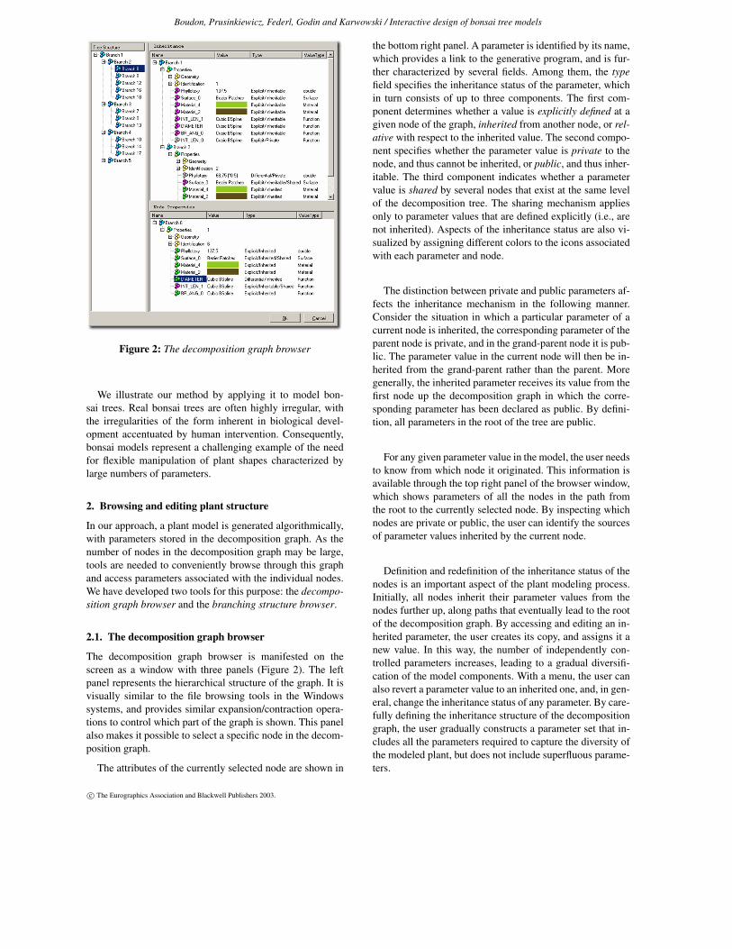
Figure 2: The decomposition graph browser
We illustrate our method by applying it to model bon-sai trees. Real bonsai trees are often highly irregular, withthe irregularities of the form inherent in biological devel-opment accentuated by human intervention. Consequently,bonsai models represent a challenging example of the needfor flexible manipulation of plant shapes characterized bylarge numbers of parameters.
2. Browsing and editing plant structure
In our approach, a plant model is generated algorithmically,with parameters stored in the decomposition graph. As thenumber of nodes in the decomposition graph may be large,tools are needed to conveniently browse through this graphand access parameters associated with the individual nodes.We have developed two tools for this purpose: the decompo-sition graph browser and the branching structure browser.
2.1. The decomposition graph browser
The decomposition graph browser is manifested on thescreen as a window with three panels (Figure 2). The leftpanel represents the hierarchical structure of the graph. It isvisually similar to the file browsing tools in the Windowssystems, and provides similar expansion/contraction opera-tions to control which part of the graph is shown. This panelalso makes it possible to select a specific node in the decom-position graph.
The attributes of the currently selected node are shown in
the bottom right panel. A parameter is identified by its name,which provides a link to the generative program, and is fur-ther characterized by several fields. Among them, the typefield specifies the inheritance status of the parameter, whichin turn consists of up to three components. The first com-ponent determines whether a value is explicitly defined at agiven node of the graph, inherited from another node, or rel-ative with respect to the inherited value. The second compo-nent specifies whether the parameter value is private to thenode, and thus cannot be inherited, or public, and thus inher-itable. The third component indicates whether a parametervalue is shared by several nodes that exist at the same levelof the decomposition tree. The sharing mechanism appliesonly to parameter values that are defined explicitly (i.e., arenot inherited). Aspects of the inheritance status are also vi-sualized by assigning different colors to the icons associatedwith each parameter and node.
The distinction between private and public parameters af-fects the inheritance mechanism in the following manner.Consider the situation in which a particular parameter of acurrent node is inherited, the corresponding parameter of theparent node is private, and in the grand-parent node it is pub-lic. The parameter value in the current node will then be in-herited from the grand-parent rather than the parent. Moregenerally, the inherited parameter receives its value from thefirst node up the decomposition graph in which the corre-sponding parameter has been declared as public. By defini-tion, all parameters in the root of the tree are public.
For any given parameter value in the model, the user needsto know from which node it originated. This information isavailable through the top right panel of the browser window,which shows parameters of all the nodes in the path fromthe root to the currently selected node. By inspecting whichnodes are private or public, the user can identify the sourcesof parameter values inherited by the current node.
Definition and redefinition of the inheritance status of thenodes is an important aspect of the plant modeling process.Initially, all nodes inherit their parameter values from thenodes further up, along paths that eventually lead to the rootof the decomposition graph. By accessing and editing an in-herited parameter, the user creates its copy, and assigns it anew value. In this way, the number of independently con-trolled parameters increases, leading to a gradual diversifi-cation of the model components. With a menu, the user canalso revert a parameter value to an inherited one, and, in gen-eral, change the inheritance status of any parameter. By care-fully defining the inheritance structure of the decompositiongraph, the user gradually constructs a parameter set that in-cludes all the parameters required to capture the diversity ofthe modeled plant, but does not include superfluous parame-ters.
c© The Eurographics Association and Blackwell Publishers 2003.

Boudon, Prusinkiewicz, Federl, Godin and Karwowski / Interactive design of bonsai tree models
Figure 3: 2D function editor, in explicit (left) and relative(right) modes
2.2. Parameter editors
Parameter values are modified using editors. An editor isopened by selecting a parameter in the panel showing thecurrent node. The exact list of parameters, and therefore theeditors, associated with the nodes depends on the underlyinggenerative algorithm. In the simplest case of scalar values,the editor is a widget with a slider and an editable numeri-cal field. More involved editors are used for compound pa-rameters (attributes) of the node. These include a materialeditor for defining optical properties of the branch, editorsof curves and surfaces, and a graphical function editor (Fig-ure 3), as described in 14.
Some parameters (scalars and functions in the present im-plementation) can be declared as relative with respect to theinherited value. If this is the case, the value of the parame-ter is a combination of a value inherited from another nodeand a value defined locally. In the case of scalars, this meansthe actual parameter value is obtained by applying a locallydefined offset (additive combination), or taking a locally de-fined fraction (multiplicative combination) of the inheritedvalue. In the case of functions, the same combinations areachieved by taking the sum or product of the inherited andlocally defined function. To facilitate the editing process, thefunction editor can show both the inherited and the modifiedfunction (Figure 3, right).
2.3. The branching structure browser
The branching structure browser (Figure 4) provides an al-ternative multiresolution view of the plant. It uses an iconicrepresentation of the branching system to visualize a chosenlevel of the plant structure, and thus shows some of its geo-metric aspects, but does not explicitly show the inheritancerelationships in the decomposition graph.
At the heart of the branching structure browser is the no-tion of the branch silhouette, which depicts the main axisand the outline (hull, envelope) of the branching systemscontained within it. The browser arranges these silhouettesinto a branching structure that conforms to the plant geom-etry at a user-selected scale. Thus, in addition to the silhou-ettes themselves, the browser visualizes the length of the in-ternodes (segments of an axis between the insertion points of
Figure 4: A screenshot of the branching structure browser.The plant is represented at scale 2. The orientation of in-stance colored in purple is currently edited. The other in-stances become transparent, and give the user a focus onthe current operation. The Edit menu displays all the possi-ble editing operations.
the consecutive branches) and the size and orientation of thebranches (defined by the branching and phyllotactic angles).
The user can change the size and orientation of a branchby selecting and manipulating it using the mouse (for a gen-eral treatment of the interactive manipulation of branchessee 12). The user can also invoke an external parameter ed-itor for the selected node. Most important in the context ofmultiscale editing is the silhouette editor, discussed in thenext section. Used together, the branching structure browserand the silhouette editor provide a means for convenientlyediting plant geometry in a manner that approaches directmanipulation.
2.4. The silhouette editor
The global geometry of a branching system is specified byits silhouette (Figure 5, see also Figure 1). The silhouetteconsists of a 3D curve, such as a polyline, a Bézier curve ora B-spline, which specifies the silhouette’s axis. The silhou-ette also includes a potentially asymmetric envelope whichrepresents the lengths of the lateral branches. Literature inbotany contains a large variety of envelope models to rep-resent the crowns of branching systems, for instance usingcones, ellipsoids 11 or convex polyhedra 3. We chose andimplemented the envelope model proposed by Horn 7 and
c© The Eurographics Association and Blackwell Publishers 2003.

Boudon, Prusinkiewicz, Federl, Godin and Karwowski / Interactive design of bonsai tree models
Figure 5: Silhouette editor.
Figure 6: Asymmetric envelopes defined by Cescatti to rep-resent the crown shapes of trees. In the left figure, the controlpoints P3 to P6 lie in the horizontal (xz) plane. In the rightfigure, points P3, P5 and P6 have been moved vertically.
Koop 9, and later extended by Cescatti 1, which was designedto flexibly represent a large variety of tree crowns in an intu-itive fashion.
The Cescatti envelope is defined by six control points andtwo shape coefficients, C1 and C2 (Figure 6). The first twocontrol points, P1 and P2, are the top and bottom points ofthe crown, respectively. The other four points, P3 through P6,describe a peripheral line at the greatest width of the crownwhen projected on the xz-plane. P3 and P5 are constrainedto the xy-plane and P4 and P6 to the yz-plane. Finally, theshape coefficients describe the curvature of the crown aboveand below the peripheral line. Mathematical details of thismodel are described in the paper by Cescatti 1.
3. Multiscale constraints
Parameters associated with different nodes of the decompo-sition graph may be related to each other not only by theinheritance pattern, but also by their meaning. An exam-
Figure 7: Relationship between silhouettes at two differentscales of plant hierarchy. The size of the silhouettes at thefiner scale is determined by the shape of the silhouette at thecoarser scale.
ple is the relationship between the shape of a silhouette ofa branching systems and the sizes of the silhouettes associ-ated with the lateral branches (Figure 7). Clearly, one cannotmodify the overall silhouette without affecting the size of theindividual branches, and vice versa. In general, the informa-tion in a parent node of the decomposition graph is relatedto that in the child nodes, because both the parent and thechildren describe the same branching system. Since this re-lation spans different scales of plant description, we call it amultiscale constraint.
Multiscale constraints can be satisfied in a bottom-up,local-to-global fashion, or in top-down, global-to-local fash-ion. These terms describe the direction in which the con-straint information propagates in the decomposition tree.The top-down direction is better suited for the interactiveplant design, which commonly begins with the overall plantsilhouette, and proceeds by gradually refining it 15 (c.f. Sec-tion 1).
At a practical level, we thus face the problem of placinga child silhouette Ec inside the parent silhouette Ep. To thisend, we add an extra control point T to the description ofthe silhouette, as shown in Figure 8. The vector
−→
BT that con-nects the base of the silhouette Ec to the point T is used toorient this silhouette in space and determine its size. First,point B is positioned at the branching point specified by thegenerative algorithm. Next, the vector
−→
BT is aligned withthe branch direction given by the branching and phyllotac-tic angles. Finally, the silhouette Ec is scaled so as to placepoint T on the parent silhouette. A reference frame associ-ated with the child silhouette Ec can optionally be used torotate it around its own axis.
The multiscale constraint discussed above relates param-eters associated with different nodes in the decompositiongraph, but does not affect its structure (topology). A morecomplicated situation occurs when the user manipulates thedensity of branch distribution along an axis. The density
c© The Eurographics Association and Blackwell Publishers 2003.

Boudon, Prusinkiewicz, Federl, Godin and Karwowski / Interactive design of bonsai tree models
Figure 8: Placement of a child silhouette Ec inside the par-ent silhouette Ep. a) The shape of both silhouettes. b) Theresult of placement.
function associated with a parent node determines the num-ber of the child nodes, and therefore affects the structure ofthe decomposition graph. According to our approach, thisstructure is generated algorithmically, which means that thegenerative algorithm must be re-run to satisfy the branchdensity constraints. The coupling between the generative al-gorithm and the interactive manipulation of parameters isschematically depicted in Figure 9, and discussed in moredetail in the next section.
Figure 9: Interaction of various components during themodeling process.
Figure 10: Effect of decoupling. a) Initial plant structure,showing the default shape of the bottom branch. b) Theshape of the bottom branch (position 0.25) was manually ad-justed. c) The branch density was increased. d) The branchdensity is restored to the original value, and all branches arestraight lines.
4. The modeling process
The user begins the modeling process by specifying a gener-ative algorithm in the L-system-based language L+C 8. (Ourmodels are constructed using the global-to-local paradigm,and thus are more properly described by Chomsky gram-mars than L-systems 15. Nevertheless, we continue to usethe term “L-systems”, because L-system and Chomsky pro-ductions can be combined seamlessly in the same model,making clear separation difficult). During its first execution,this algorithm makes calls to functions that create the de-composition graph and define parameters for some nodes.The nodes for which the parameter values have not been ex-plicitly defined inherit their values from the parent nodes, asdescribed in Section 2.1. Specifically, if the initial executionof the algorithm defines parameter values for the root only,all nodes of the decomposition graph will share the same setof values.
Once the initial decomposition graph has been created, theparameters contained within it can be interactively edited.Following that, the generative algorithm must be re-run to re-construct the plant structure. In principle, the algorithm thenaccesses the values stored in the decomposition graph. Toassociate the nodes of the graph with the specific branchesof the generated structure, the branches and the nodes areidentified by their paths to the top of the decomposition tree.A path of a node is recursively defined by three components:
• the path of the node’s parent;• the normalized position of the branch along the axis;• a number identifying the branch, if several branches are
attached to the same point of their supporting axis.
Unfortunately, storing an algorithm’s parameters in thedecomposition tree may lead to problems. As a result ofparameter manipulation, the paths assigned to the branchesduring the re-execution of the generative algorithm may dif-
c© The Eurographics Association and Blackwell Publishers 2003.

Boudon, Prusinkiewicz, Federl, Godin and Karwowski / Interactive design of bonsai tree models
fer from the paths stored in the decomposition graph. Thiswill occur, for example, if the user has changed the func-tion that defines the density of branch distribution along anaxis (c.f Section 3). In the case of such a decoupling, thegenerative algorithm removes the nodes that are no longerused, and adds new nodes to the decomposition graph forthose branches that do not have a corresponding node. Theseadjustments may have unintuitive consequences from theuser’s perspective. Consider the example illustrated in Fig-ure 10. The branch density function for the initial plantstructure (a) determines the main axis will have three lateralbranches. The normalized positions of these lateral branchesare 0.25, 0.5 and 0.75, respectively. By default, all axes arestraight. Now, suppose the user changes the shape of the bot-tom branch to a curved one, as illustrated in Figure (b). Next,the user changes the branch density of the main axis, increas-ing the number of lateral branches to four. When the algo-rithm regenerates the plant structure, it attempts to obtainparameter values for the branches whose normalized posi-tions are 0.2, 0.4, 0.6 and 0.8. These paths, however, do notcorrespond to any of the existing nodes in the decomposi-tion graph. Consequently, new nodes are created for all thelateral branches, while the old ones are removed from thegraph. The new nodes are assigned default parameter val-ues, which results in the structure shown in Figure (c). Theshape of the axis associated with node 0.25 is now perma-nently lost. Thus, even if the branch density is later returnedto the original value, the algorithm will not restore the bot-tom branch to its curved shape (Figure d).
The problem described above can be attributed to the factthat the management of parameters is decoupled from thealgorithm that uses them to construct the plant. We perceivethis problem as a very fundamental one: in order to interactwith the plant, we personalize each branch so that we can se-lect and modify it. Unfortunately, there is no robust methodfor maintaining the identity of branches during modificationsthat may displace them, of even temporarily remove themfrom the structure. In practice, we reduce the impact of thisproblem by first defining the distribution of the branches,then modifying their shape from the default.
5. Results
We applied our method to model a number of bonsai trees.They present a challenging modeling problem because oftheir highly irregular structures. While real bonsai trees are aresult of interplay between biological development and hu-man intervention, our models are the result of interplay be-tween the biologically-based generative algorithms and in-teractive manipulation.
The results are shown in Figures 11 to 15. For reference,we also show some of the real plants we attempted to model.Each model was created in approximately 3 hours.
On a PC with a 1 GHz Pentium III processor, the process
Figure 11: Bonsai 1 : bunjinji style, photograph from 2
of generating the detailed models of bonsai shown in Fig-ures 11, 13, 14 and 15 takes between 1 and 2.5 seconds. Themodels in Figure 12 were the longest to generate (10 and12.5 seconds) due to the large number of needles (modeledas generalized cylinders).
6. Conclusions
We have presented an approach for modeling plants based ona global-to-local design methodology, consistent with artis-tic techniques. To this end, we formalized a multiscale modelof a plant by defining a decomposition tree, the nodes ofwhich represent specific branches of the plant structure. Theparameters needed to construct the plant are then associatedwith the nodes of the decomposition tree. We proposed in-heritance and parameter sharing as a method for minimizingthe total number of parameters needed, while giving the userthe opportunity to refine any aspect of the model. Our ap-
Figure 12: Bonsai 2: nejikan style (twisted cascade) andBonsai 3: fukinagashi style (windswept)
c© The Eurographics Association and Blackwell Publishers 2003.

Boudon, Prusinkiewicz, Federl, Godin and Karwowski / Interactive design of bonsai tree models
Figure 13: Bonsai 4: chokkan style (formal upright), photograph from 2
Figure 14: Bonsai 5: sankan style, with three branches orig-inating at the same point
proach alleviates the difficulty of managing and navigatingthrough a complex parameter space, which is an issue in in-teractive plant design 4, 10. We also observed the impact ofmultiscale constraints on the modeling process.
At a practical level, we have implemented a system basedon the above paradigms. It consists of tools that allow theuser to select a branching structure at any level of the hier-archical plant organization, and interactively edit its param-eters. We found that these tools make it possible to design
Figure 15: Bonsai 6: kengai style (formal cascade), photo-graph from 2
plant models relatively quickly and in an intuitive manner.Finally, we have demonstrated the usefulness of our systemby modeling several bonsai trees.
There are a number of areas where our results can be fur-ther improved. We believe the issue of attributes being de-coupled from the procedural algorithm deserves more ex-amination. For example, we could associate nodes in the de-composition graph with ranges of branch positions, ratherthan single position, thus potentially reducing the decou-pling artifacts discussed in Section 4 (Figure 10).
The attribute inheritance mechanism we have consideredin this paper only relates branches at different scales. Thisapproach is well suited for modeling monopodial plants,
c© The Eurographics Association and Blackwell Publishers 2003.

Boudon, Prusinkiewicz, Federl, Godin and Karwowski / Interactive design of bonsai tree models
with a clear distinction between the parent axis and its lat-erals. However, in sympodial plants a branch may supportanother branch at the same scale 6. To facilitate modelingof sympodial plants, our inheritance mechanism should beextended to within-scale relationships between the nodes.
Finally, the visual quality of our models could be im-proved by adding more details using displacement mapping.
Acknowledgments
We would like to thank Christophe Pradal for his precioushelp, Christophe Nouguier for his first implementation ofthe GEOM library which provided good support for ourwork, Frank Perbet, Lars Mündermann and Brendan Lanefor their explanations and advice, Jennifer Walker for hereditorial help, and all the people from the University ofCalgary Graphics Jungle Laboratory for creating such afriendly working environment. This work was supported bythe France-Canada Research Foundation, Natural Sciencesand Engineering Research Council of Canada, and InstitutNational de la Recherche Agronomique, France.
References
1. A. Cescatti. Modelling the radiative transfer in dis-continuous canopies of asymmetric crowns. I. Modelstructure and algorithms. Ecological Modeling. 101(2-3):263–274, 1997.
2. R. R. Clark and P. Voynovich. Outstanding ameri-can bonsai: A photographic essay on the works of fiftyamerican bonsai artists. Timber Press, September 1989.
3. C. Cluzeau, J. L. Dupouey, and B. Courbaud. Poly-hedral representation of crown shape. A geometrictool for growth modelling. Annals of Forest Science.52:297–306, 1995.
4. O. Deussen and B. Lintermann. A modelling methodand user interface for creating plants. In Proceedingsof Graphics Interface ’97, pages 189–197, 1997.
5. D. R. Forsey and R. H. Bartels. Hierarchical B-splinerefinement. Proceedings of SIGGRAPH 1988 (Atlanta,Georgia, August 1-5, 1988) in Computer Graphics, 22,4 (August 1988), pages 205–212, ACM SIGGRAPH,New York, 1988.
6. C. Godin and Y. Caraglio. A multiscale model of planttopological structures. Journal of Theoretical Biology,191:1–46, 1998.
7. H. S. Horn. The adaptive geometry of trees. PrincetonUniversity Press. Princeton, N.J. 1971.
8. R. Karwowski. Improving the process of plant model-ing: The L+C modeling language. Ph.D. thesis, Univer-sity of Calgary, October 2002.
9. H. Koop. SILVI-STAR: A comprehensive monitoringsystem. Forest Dynamics. Springer, Berlin, pp. 229,1989.
10. B. Lintermann and O. Deussen. Interactive modelingof plants. IEEE Computer Graphics and Applications,19(1):56–65, 1999.
11. J. M. Norman and J. L. Welles. Radiative transfer inan array of canopies. Agronomy Journal. 75:481–488,1983.
12. J. Power, A. J. Bernheim-Brush, P. Prusinkiewicz, andD. Salesin. Interactive arrangement of botanical L-system models, 1999. Proceedings of the 1999 ACMSymposium on Interactive 3D Graphics (Atlanta, Geor-gia, April 26–28, 1999), pp. 175–182.
13. P. Prusinkiewicz, M. James, and R. Mech. Synthetictopiary. Proceedings of SIGGRAPH 1994 (Orlando,Florida, July 24–28, 1994). ACM SIGGRAPH, NewYork, 2001, pp. 351–358.
14. P. Prusinkiewicz, R. Karwowski, R. Mech, andJ. Hanan. L-studio/cpfg: A software system for mod-eling plants. In M. Nagl, A. Schürr, and M. Münch,editors, Applications of graph transformation with in-dustrial relevance, Lecture Notes in Computer Science1779, pages 457–464. Springer-Verlag, Berlin, 2000.
15. P. Prusinkiewicz, L. Mündermann, R. Karwowski, andB. Lane. The use of positional information in the mod-eling of plants. Proceedings of SIGGRAPH 2001 (LosAngeles, California, August 12–17, 2001). ACM SIG-GRAPH, New York, 2001, pp. 289–300.
16. W. T. Reeves and R. Blau. Approximate and proba-bilistic algorithms for shading and rendering structuredparticle systems. Proceedings of SIGGRAPH ’85 (SanFrancisco, California, July 22-26, 1985), in ComputerGraphics, 19, 3 (July 1985), pages 313–322, ACMSIGGRAPH, New York, 1985.
17. I. Shlyakhter, M. Rozenoer, J. Dorsey, and S. Teller.Reconstructing 3D tree models from instrumented pho-tographs. IEEE Computer Graphics and Applications,21(3):53–61, 2001.
18. E. J. Stollnitz, T. D. DeRose, and D. H. Salesin.Wavelets for computer graphics: theory and applica-tions. Morgan Kaufman, San Francisco, CA, 1996.
19. J. Weber and J. Penn. Creation and rendering of re-alistic trees. Proceedings of SIGGRAPH ’95 (LosAngeles, California, August 6–11, 1995). ACM SIG-GRAPH, New York, 1995, pp. 119–128.
20. D. Zorin, P. Schröder, and W. Sweldens. Interactivemultiresolution mesh editing. Proceedings of SIG-GRAPH 1997 (Los Angeles, California, August 3–8,1997), pp. 259–268.
c© The Eurographics Association and Blackwell Publishers 2003.