Embed Size (px)
Citation preview
Int J Fract (2009) 159:191–207DOI 10.1007/s10704-009-9393-9
ORIGINAL PAPER
Interaction between a crack and a circular inhomogeneitywith interface stiffness and tension
Sofia G. Mogilevskaya · Steven L. Crouch ·Roberto Ballarini · Henryk K. Stolarski
Received: 18 March 2009 / Accepted: 4 August 2009 / Published online: 3 September 2009© Springer Science+Business Media B.V. 2009
Abstract The interaction between a straight crackand a circular inhomogeneity with interface stiffnessand energy is considered. The Gurtin and Murdochmodel is adopted, wherein the interface between theinhomogeneity and the matrix is regarded as a mate-rial surface that possesses its own mechanical proper-ties and surface tension. The elastostatics problem isdecomposed into two complimentary problems for (1)a circular disk with unknown distributions of tractionand displacements along its boundary and (2) a loadedisotropic plane containing a circular hole with unknowndistributions of traction and displacements along itsboundary. The unknown distributions are determinedthrough the application of the constitutive relations atthe material surface. For selected values of the dimen-sionless parameters that quantify the geometry, mate-rial properties and applied loading, the stress field,stress intensity factors and energy release rates arecalculated using a complex boundary integral equa-tion approach. Particular attention is paid to crack-tipshielding and anti-shielding that develops as a resultof the stresses introduced by the material surface. Anillustrative example involving a perforated plate loadedin tension suggests that the material surface producesa modest level of expected effective toughening.
S. G. Mogilevskaya (B) · S. L. Crouch · R. Ballarini ·H. K. StolarskiDepartment of Civil Engineering, University of Minnesota,500 Pillsbury Drive S.E., Minneapolis, MN 55455, USAe-mail: [email protected]
Keywords Circular inhomogeneity · Gurtin andMurdoch model · Surface tension · Surface elasticity ·Straight crack · Complex boundary integral equation
1 Introduction
This paper presents the results of a two-dimensionalelastostatics analysis of the effects of surface stresson the interaction between a matrix crack and a circu-lar inhomogeneity. The surface stress is accounted forthrough the Gurtin and Murdoch model of a materialsurface (Gurtin and Murdoch 1975, 1978), wherein theinterface between the matrix and the inhomogeneity isregarded as a material surface possessing its own elas-ticity and surface tension. Particular attention is paid tothe potential reduction in flaw sensitivity of the matrixresulting from the residual stresses produced just out-side the inhomogeneity by the interface tension andelasticity.
The Gurtin and Murdoch model has received ren-ewed attention because of the potential influence of sur-face effects on the mechanical properties and responseof nanoscale structures that involve relatively large sur-face-to-volume ratios. Most applications of the modelto date involve analyses of the stress fields producedby isolated spherical or cylindrical inhomogeneitiesembedded in an infinite or semi-infinite matrix (Millerand Shenoy 2000; Sharma and Ganti 2002, 2004;Sharma et al. 2003; Yang 2004; Duan et al. 2005a,b,c,2006, 2007; He and Li 2006; Huang and Wang 2006;
123
192 S. G. Mogilevskaya et al.
Lim et al. 2006; Mi and Kouris 2006; Chen et al.2007; Zhang and Wang 2007; Tian and Rajapakse2007a,b). Most of the papers, including Tian and Rajap-akse (2007c) two-dimensional finite element methodformulation for the analysis of multiple interactinganisotropic inhomogeneities, invoke simplifications ofGurtin and Murdoch’s constitutive equations made byneglecting a whole or a part of the term associated withthe gradient of surface displacement. Mogilevskayaet al. (2008) provided a basis for critical review of thesignificance to inhomogeneity problems of such sim-plifications by deriving the precise component forms ofGurtin and Murdoch’s three-dimensional equations forinterfaces of arbitrary shape, and applying the completemodel to the two-dimensional problem of multiple,arbitrarily located, interacting circular inhomogenei-ties. They showed that the stress and strain fields in thevicinity of the interface are sensitive to the choice ofthe interface constitutive law.
Application of simplified forms of the Gurtin andMurdoch model to problems involving point defectsand cracks include the analysis of interaction of an edgedislocation with a single inhomogeneity (Fang and Liu2006; Fang et al. 2007), and the configurational equi-librium of isolated cracks and voids (Rajapakse 1975;Thomson et al. 1986; Chuang 1987; Wu 1999; Wuand Wang 2001). No results are available, however, forthe interaction of a crack and an inhomogeneity. Thisopen problem is worth exploring because the surfacetension and surface elasticity produce residual stressfields in the vicinity of the material surface that caneither suppress or enhance crack initiation and propa-gation within the matrix. He and Li’s closed-form solu-tion for the stress field produced by a spherical void inan infinite matrix demonstrated that significant tensileand compressive stresses develop just outside the void.Because the Gurtin and Murdoch model introducesan intrinsic length scale, the magnitude of the resid-ual stresses increase with decreasing hole-size. For therepresentative parameters considered in their paper, theresidual stress can approach the better part of a GPa.
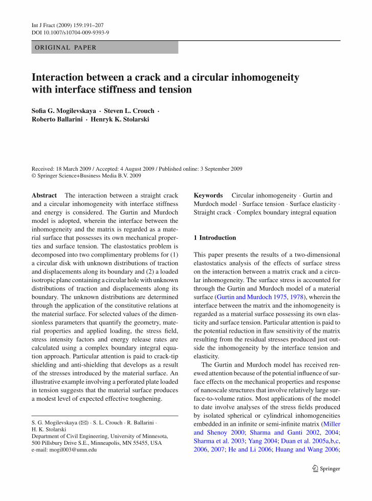
This paper explores the expected amount of shield-ing/antishielding induced by the residual stress fieldon the tips of a matrix crack. The configuration con-sidered involves a straight crack interacting with a cir-cular inhomogeneity (Fig. 1). The surface effects areincluded only on the interface between the circularinhomogeneity and the matrix. Even though it is clearthat those effects are also present on the surface of the
Fig. 1 Problem formulation
crack, their precise analysis is still elusive in spite ofseveral past contributions in that area. Various possiblemodeling approaches have been discussed, for exam-ple, by Oh et al. (2006) but no systematic and widelyaccepted methodology of solving the problem hasemerged. There are approximate methods of solvingthe problem of a crack with surface effects, such a veryskillful approach presented by Wu (1999). However, hisapproach is based either on the overall energy consid-erations or includes surface effects approximately, byconsidering geometry of the deformed crack surfaceswithout those effects (acknowledging the difficultieswith the systematic solution of the problem). Further-more, his approach provides only the modifications tothe stress intensity factors, which is not sufficient inthe analysis of the complete boundary value problem,as done in this work. Thus, we have decided to considera crack without surface effects in the believe that thoseeffects (whatever they are) will be superposed with theeffects that we discuss herein.
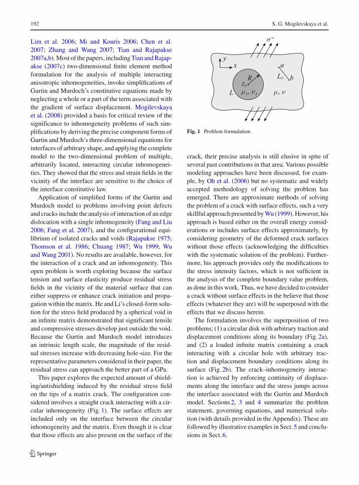
The formulation involves the superposition of twoproblems; (1) a circular disk with arbitrary traction anddisplacement conditions along its boundary (Fig. 2a),and (2) a loaded infinite matrix containing a crackinteracting with a circular hole with arbitrary trac-tion and displacement boundary conditions along itssurface (Fig. 2b). The crack–inhomogeneity interac-tion is achieved by enforcing continuity of displace-ments along the interface and the stress jumps acrossthe interface associated with the Gurtin and Murdochmodel. Sections 2, 3 and 4 summarize the problemstatement, governing equations, and numerical solu-tion (with details provided in the Appendix). These arefollowed by illustrative examples in Sect. 5 and conclu-sions in Sect. 6.
123
Interaction between a crack and a circular inhomogeneity 193
(a) (b)
Fig. 2 a A circular disc. b A circular hole and a crack in aninfinite plane
2 Problem statement
Consider (Fig. 1) the two-dimensional, plane strainproblem of an infinite, isotropic elastic plane containinga perfectly bonded circular, isotropic elastic inhomo-geneity interacting with a straight crack. The crack isarbitrarily located outside of the region defined by theinhomogeneity but does not intersect its boundary. Theelastic properties of the inhomogeneity are quantifiedthrough the shear modulus µ1 and Poisson’s ratios ν1
while those of the plane are µ, and ν. Let R and Ldenote the radius and boundary of the inhomogeneity,and z0 = z01+i z02 (i = √−1) the complex coordinateof its center. We suppose that a = a1+ia2, b = b1+ib2
are the complex coordinates of the beginning and endpoints of the crack with the boundary Lc. The inter-face between the inhomogeneity and the plane (matrix)is modeled as a material surface of vanishing thick-ness adhering to the bulk material without slipping.This surface is characterized by elastic constants (shearmoduli µ0 and Lamé parameters λ0) and the residualsurface tension σ0. The crack is either traction free orloaded with the prescribed pressure σ c(t), t ∈ Lc. Theapplied loading consists of a biaxial stress field at infin-ity (σ∞
xx , σ∞yy , σ
∞xy ). The distributions of stresses, dis-
placements, and strains in the composite and the stressintensity factors at the crack tips are to be determined.
3 Governing equations
3.1 Boundary integral equations
The problem can be decomposed into two problems: thefirst is an elastic disc whose boundary is subjected to anunknown distributions of tractions and displacementsand the second is an isotropic elastic plane contain-ing a crack and a hole whose boundary is subjected to
unknown distributions of tractions and displacements.The two problems are interrelated through the Gur-tin and Murdoch interface boundary conditions (Gurtinand Murdoch 1975).
Each elastostatic problem is formulated by usingthe direct boundary integral method, where all theelastic fields are represented in integral form via theSomigliana identities. The solution relies on the com-plex variables boundary element method describedin Mogilevskaya and Linkov (1998), Linkov andMogilevskaya (1998) and Linkov (2002).
The system of complex boundary integral equationsfor the problem includes the following:
(i) Somigliana’s traction identity at the boundaryof the disc (Linkov and Mogilevskaya 1998;Linkov 2002)
2π iκ1 + 1
4µ1σ inh(t)
= 2∫
L
uinh(τ )
(τ − t)2dτ
−∫
L
uinh(τ )∂
∂td K1(τ, t)
−∫
L
uinh(τ )∂
∂td K2(τ, t)
+1 − κ1
2µ1
∫
L
σ inh(τ )
τ − tdτ
− κ1
2µ1
∫
L
σ inh(τ )∂
∂tK1(τ, t)dτ
+ 1
2µ1
∫
Lk
σ inh(τ )∂
∂tK2(τ, t)d τ̄ (1)
where the superscript inh indicates the elasticfields for the inhomogeneity; t = x + iy is com-plex coordinate of a point (x, y) on the contourL; κ1 = 3 − 4ν1; σ inh(t) = σ inh
n (t) + iσ inh� (t)
are the complex tractions at the boundary pointt in a local coordinate system shown in Fig. 2a;uinh(τ ) = uinh
x (τ ) + iuinhy (τ ) are the complex
displacements at the boundary point τ in a globalcoordinate system; and a bar over a symboldenotes complex conjugation. The direction ofintegration is counterclockwise along boundaryL .
123
194 S. G. Mogilevskaya et al.
The two kernels in Eq. (1) are:
K1(τ, t) = lnτ − t
τ̄ − t̄, K2(τ, t) = τ − t
τ̄ − t̄(2)
(ii) Boundary integral equation at the boundaryof the hole or crack [obtained by summingSomigliana’s traction identity for the infiniteplane with the hole with the complex hypersin-gular integral equation for the crack (Linkov andMogilevskaya 1998; Linkov 2002)]
2∫
L
umat(τ )
(τ − t)2dτ
−∫
L
umat(τ )∂
∂td K1(τ, t)
−∫
L
umat(τ )∂
∂td K2(τ, t)
+1 − κ
2µ
∫
L
σmat(τ )
τ − tdτ
− κ
2µ
∫
L
σmat(τ )∂
∂tK1(τ, t)dτ
+ 1
2µ
∫
L
σmat(τ )∂
∂tK2(τ, t)d τ̄
+2∫
Lc
uc(τ )
(τ − t)2dτ
−∫
Lc
uc(τ )∂
∂td K1(τ, t)
−∫
Lc
uc(τ )∂
∂td K2(τ, t)
= 2π i1 + κ
4µ
[ασ(t)
+σ∞(t)], t ∈ L ∪ Lc (3)
where the superscript mat indicates the elasticfields for the matrix; κ = 3 − 4ν; the complexdisplacements umat(τ ) and the complex tractionsσmat(t) are defined similarly as those for the disc;uc(τ ) = uc
x (τ ) + iucy(τ ) is the complex
displacement discontinuity at the point τ ∈ Lc
in a global coordinate system, σ∞ is a complexfunction that can be expressed via the stress atinfinity as follows (Mogilevskaya and Crouch2001):
σ∞(t) = −[σ∞
xx + σ∞yy
+dt̄
dt
(σ∞
yy − σ∞xx − 2iσ∞
xy
) ]; (4)
dt̄/dt = exp(−2iβ); β is the angle between theaxis Ox and tangent at the point t ; and the coef-ficients α and the function σ(t) are defined asfollows:
α={
1 t ∈ L2 t ∈ Lc
, σ (t)={σmat(t) t ∈ Lσ c(t) t ∈ Lc
(5)
The direction of integration is clockwise for theboundary of the hole L and arbitrary for theboundary of the crack Lc. The unit normal npoints to the right of the direction of travel (i.e.inside the hole); the unit tangent � is directed inthe direction of integration (Fig. 2b).
(iii) Gurtin and Murdoch equations for the mate-rial surface (Mogilevskaya et al. 2008). The realvariables forms of the equations are:
(a) Kinematic equations for the material sur-face. They include definitions of strainεsur
εsur = ∂u�∂s
+ un
R(6)
and rotation ωsur
ωsur = −u�R
+ ∂un
∂s(7)
where u� and un are tangential and normalcomponents of surface displacements in alocal coordinate system shown in Fig. 2aand s is the arc length of the undeformedsurface.
(b) Constitutive equation for the surface
σ sur = σ0 + (2µ0 + λ0)εsur (8)
where σ sur is a one-dimensional surfacestress.
(c) Continuity of displacements along thematerial surface
uinhx =umat
x =ux , uinhy =umat
y =uy (9)
(d) Surface equilibrium conditions
σ inh� − σmat
� = ∂σ sur
∂s+ σ0ω
sur
R
σ inhn − σmat
n = − 1
Rσ sur + σ0∂ω
sur
∂s
(10)
123
Interaction between a crack and a circular inhomogeneity 195
Often times only the first terms on the right handsides of the above equations are retained. However, inmany situations (e.g. large surface tension σ0, smallradius R of the inhomogeneity) the second terms havebeen shown (Mogilevskaya et al. 2008) to have signif-icant effects. The presence of those terms reflects thefact that the true surface stress is tangent to the sur-face deformed configuration, while Eqs. (10) are writ-ten in its initial configuration. Relative to that initialconfiguration, the stress tensor has a tangent compo-nent described by Eq. (8) and a normal component ofmagnitude σ0ω
sur. The second terms of the right-handside of Eqs. (10) represent contributions of that normalcomponent to the surface equilibrium conditions.
It was shown in Mogilevskaya et al. (2008) that theGurtin and Murdoch equations for the material surfacecan be expressed in the following complex forms:
uinh(τ ) = umat(τ ) = u(τ ) (11)
σ inhn (τ )− σmat
n (τ ) = − 1
R
[σ0+(2µ0 + λ0)Re
∂u(τ )
∂τ
]
−σ0Re
[∂2u(τ )
∂τ 2 g−1(τ )
]
σ inh� (τ )−σmat
� (τ )= −(2µ0 + λ0)Im
[∂2u(τ )
∂τ 2 g−1(τ )
]
−σ0
RIm∂u(τ )
∂τ
where
g(τ ) = R
τ − z0(12)
It can be seen from Eqs. (10) and (7) that whenR → ∞, the jump in the tangential component oftractions is entirely due to surface elasticity; while thejump in the normal component is entirely due to sur-face tension. In the simplified versions of the Gurtinand Murdoch equations (employed in most of the pub-lications on the topic) the term ωsur is neglected andthus the jump in normal component vanishes whenR → ∞.
3.2 Evaluation of the elastic fields in the compositesystem and the stress intensity factors at the cracktips
The displacements and stresses at any point in thecomposite can be expressed in terms of two complexKolosov–Muschelishvili potentials ϕ(z) and ψ(z) by
using well-known Kolosov–Muschelishvili formulae(Muskhelishvili 1959). After the solution of the sys-tem (1), (3), and (11), the expressions for the potentialscan be written in terms of integrals of known boundarytractions and stresses at infinity as follows:
(a) potentials for the circular disc (Linkov andMogilevskaya 1998; Linkov 2002)
ϕ(z) = − 1
2π i(κ1 + 1)
∫
L
σ inh(τ ) ln(τ − z)dτ
+ µ1
π i(κ1 + 1)
∫
L
u(τ )
τ − zdτ (13)
ψ(z) = − 1
2π i(κ1 + 1)
⎡⎣∫
L
σ inh(τ )τ
τ − zdτ
+κ1
∫
L
σ inh(τ ) ln(τ − z)dτ
⎤⎦
+ µ1
π i(κ1 + 1)
⎡⎣∫
L
u(τ )dτ
τ − z
−∫
L
u(τ )
τ − zdτ
⎤⎦
(b) potentials for the bulk material of the matrix(Linkov and Mogilevskaya 1998; Linkov 2002)
ϕ(z) = ϕh(z)+ ϕc(z)+ ϕ∞(z)ψ(z) = ψh(z)+ ψc(z)+ ψ∞(z)
where
ϕh(z) = 1
2π i(κ + 1)
⎡⎣−
∫
L
σmat(τ ) ln(τ−z)dτ
+ 2µ∫
L
u(τ )
τ − zdτ
⎤⎦ (14)
ψh(z) = 1
2π i(κ + 1)
⎧⎨⎩−
⎡⎣∫
L
σmat(τ )τ
τ − zdτ
+κ∫
L
σmat(τ ) ln(τ − z)dτ
⎤⎦
123
196 S. G. Mogilevskaya et al.
+2µ
⎡⎣∫
L
u(τ )dτ
τ − z
−∫
L
u(τ )
τ − zdτ
⎤⎦⎫⎬⎭
ϕc(z) = 1
2π i(κ + 1)
⎡⎢⎣−
∫
Lc
σ c(τ ) ln(τ − z)dτ
+ 2µ∫
Lc
uc(τ )
τ−zdτ
⎤⎥⎦ (15)
ψc(z) = 1
2π i(κ + 1)
⎧⎪⎨⎪⎩−
⎡⎢⎣∫
Lc
σ c(τ )τ
τ − zdτ
+κ∫
Lc
σ c(τ ) ln(τ − z)dτ
⎤⎥⎦
+2µ
⎡⎢⎣∫
Lc
uc(τ )dτ
τ − z
−∫
Lc
uc(τ )
τ − zdτ
⎤⎥⎦⎫⎪⎬⎪⎭
and where the potentials at infinity are as follows:
ϕ∞(z) = σ∞xx + σ∞
yy
4z
ψ∞(z) = σ∞yy − σ∞
xx + 2iσ∞xy
2z (16)
The displacements are defined up to some additionalterms, which can be found by a procedure similar to theone described in Mogilevskaya et al. (2008).
The stress intensity factors at the tips of the crackcan be calculated from the following expressions(Mogilevskaya 1996):
(K1 − i K2)a
= −√
2πµi
κ + 1exp (−iθ1/2) lim
τ→a
(u√τ − a
)
(K1 − i K2)b
= −√
2πµi
κ + 1exp (−iθ2/2) lim
τ→b
(u√b − τ
)(17)
where θ1 (θ2) is the angle between the axis Ox and thetangent to the tip a (b).
4 Numerical solution
4.1 Circular disc
We expand the unknown tractions σ inh(τ ) and the dis-placements u(τ ) at the boundary of the disc into com-plex Fourier series of the forms
σ inh(τ ) =∞∑
m=1
Binh−m gm(τ )
+∞∑
m=0
Binhm g−m(τ ), τ ∈ L (18)
uinh(τ ) = u(τ )
=∞∑
m=1
A−m gm(τ )
+∞∑
m=0
Am g−m(τ ), τ ∈ L (19)
where g(τ ) is defined by Eq. (12). The complex coef-ficients in series (18) and (19) are unknown. Aftersubstituting expressions (18) and (19) into Eq. (1), eval-uating all integrals analytically and using the propertiesof complex Fourier series, the coefficients for the trac-tions (Binh−m, Binh
m ) can be expressed in terms of thosefor the displacements (A−m, Am) (see Mogilevskayaet al. 2008 for more details).
4.2 Infinite plane containing the hole and the crack
The complex Fourier series for the unknown tractionsσmat(τ ) at the boundary of the hole can be written asfollows
σmat(τ ) =∞∑
m=1
Bmat−m gm(τ )
+∞∑
m=0
Bmatm g−m(τ ), τ ∈ L (20)
The displacements u(τ ) at the same boundary can berepresented by series (19) due to condition (11).
To represent the unknown displacement discontinu-ities at the boundary of the cracks we first map the cracksegment [a, b] onto the segment [−1, 1] as follows:
123
Interaction between a crack and a circular inhomogeneity 197
s = 2τ − a − b
b − a, τ ∈ Lc
The displacement discontinuity distributionuc(s)along the segment [−1, 1] is then approximated byseries of Chebyshev polynomials multiplied by aweight function
√1 − s2
uc(s) =√
1 − s2∞∑
n=0
dnUn (s) (21)
where Un (s) is the Chebyshev polynomial of the sec-ond kind defined as
Un (s) = sin [(n + 1) arccos s]
sin (arccos s)(22)
The weight function involved in Eq. (21) is intro-duced to take into account the correct tip asymptotics.The complex coefficients in series (20) and (21) areunknown.
Using relations (19) and (11), we can express thecoefficients for the tractions (Bmat−m , Bmat
m ) in terms ofthose for the displacements (A−m, Am) (seeMogilevskaya et al. (2008) for more details). Thus, onecan rewrite Eq. (3) in terms of unknown coefficientsfor the displacements and displacement discontinuitiesonly. After these coefficients are determined, the trac-tions and displacements at the boundary of the inho-mogeneity and the displacement discontinuities at theboundary of the crack can be found. The procedure ofdetermining the unknown coefficients for the displace-ments and displacement discontinuities is outlined inthe Appendix 1.
The displacements, stresses, strains and stress inten-sity factors in the system can be evaluated as explainedin Appendix 2.
5 Examples
5.1 Parametric studies
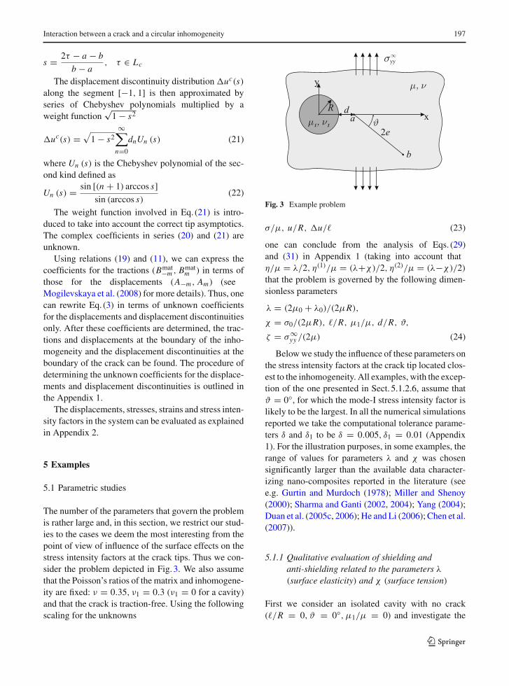
The number of the parameters that govern the problemis rather large and, in this section, we restrict our stud-ies to the cases we deem the most interesting from thepoint of view of influence of the surface effects on thestress intensity factors at the crack tips. Thus we con-sider the problem depicted in Fig. 3. We also assumethat the Poisson’s ratios of the matrix and inhomogene-ity are fixed: ν = 0.35, ν1 = 0.3 (ν1 = 0 for a cavity)and that the crack is traction-free. Using the followingscaling for the unknowns
Fig. 3 Example problem
σ/µ, u/R, u/� (23)
one can conclude from the analysis of Eqs. (29)and (31) in Appendix 1 (taking into account thatη/µ = λ/2, η(1)/µ = (λ+χ)/2, η(2)/µ = (λ−χ)/2)that the problem is governed by the following dimen-sionless parameters
λ = (2µ0 + λ0)/(2µR),
χ = σ0/(2µR), �/R, µ1/µ, d/R, ϑ,
ζ = σ∞yy /(2µ) (24)
Below we study the influence of these parameters onthe stress intensity factors at the crack tip located clos-est to the inhomogeneity. All examples, with the excep-tion of the one presented in Sect. 5.1.2.6, assume thatϑ = 0◦, for which the mode-I stress intensity factor islikely to be the largest. In all the numerical simulationsreported we take the computational tolerance parame-ters δ and δ1 to be δ = 0.005, δ1 = 0.01 (Appendix1). For the illustration purposes, in some examples, therange of values for parameters λ and χ was chosensignificantly larger than the available data character-izing nano-composites reported in the literature (seee.g. Gurtin and Murdoch (1978); Miller and Shenoy(2000); Sharma and Ganti (2002, 2004); Yang (2004);Duan et al. (2005c, 2006); He and Li (2006); Chen et al.(2007)).
5.1.1 Qualitative evaluation of shielding andanti-shielding related to the parameters λ(surface elasticity) and χ (surface tension)
First we consider an isolated cavity with no crack(�/R = 0, ϑ = 0◦, µ1/µ = 0) and investigate the
123
198 S. G. Mogilevskaya et al.
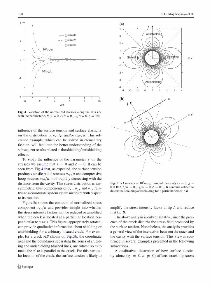
Fig. 4 Variation of the normalized stresses along the axis Oxwith the parameter r/R (λ = 0, �/R = 0, µ1/µ = 0, ζ = 0.0)
influence of the surface tension and surface elasticityon the distribution of σrr/µ and/or σθθ/µ. This ref-erence example, which can be solved in elementaryfashion, will facilitate the better understanding of thesubsequent results related to the shielding/antishieldingeffects.
To study the influence of the parameter χ on thestresses we assume that λ = 0 and ζ = 0. It can beseen from Fig. 4 that, as expected, the surface tensionproduces tensile radial stresses σrr/µ and compressivehoop stresses σθθ/µ, both rapidly decreasing with thedistance from the cavity. This stress distribution is axi-symmetric, thus components of σxx , σyy and σxy rela-tive to a coordinate system xy are invariant with respectto its rotation.
Figure 5a shows the contours of normalized stresscomponent σyy/µ and provides insight into whetherthe stress intensity factors will be reduced or amplifiedwhen the crack is located at a particular location per-pendicular to y axis. This figure, appropriately rotated,can provide qualitative information about shielding orantishielding for a arbitrary located crack. For exam-ple, for a crack AB shown on Fig. 5b, the coordinateaxes and the boundaries separating the zones of shield-ing and antishielding (dashed lines) are rotated so as tomake the x ′ axis parallel to the crack. For this particu-lar location of the crack, the surface tension is likely to
(a)
(b)
Fig. 5 a Contours of 103σyy/µ around the cavity (λ = 0, χ =0.00083, �/R = 0, µ1/µ = 0, ζ = 0.0), b contours rotated todetermine shielding/antishielding for a particular crack AB
amplify the stress intensity factor at tip A and reduceit at tip B.
The above analysis is only qualitative, since the pres-ence of the crack disturbs the stress field produced bythe surface tension. Nonetheless, the analysis providesa general view of the interaction between the crack andthe cavity with the surface tension. This view is con-firmed in several examples presented in the followingsubsections.
A qualitative illustration of how surface elastic-ity alone (χ = 0, λ �= 0) affects crack tip stress
123
Interaction between a crack and a circular inhomogeneity 199
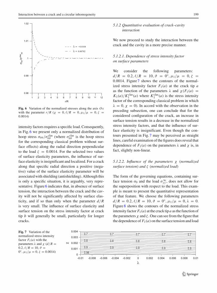
Fig. 6 Variation of the normalized stresses along the axis Oxwith the parameter r/R (χ = 0, �/R = 0, µ1/µ = 0, ζ =0.0014)
intensity factors requires a specific load. Consequently,in Fig. 6 we present only a normalized distribution ofhoop stress σθθ/σ clas
θθ (where σ clasθθ is the hoop stress
for the corresponding classical problem without sur-face effects) along the radial direction perpendicularto the load ζ = 0.0014. For the selected two valuesof surface elasticity parameters, the influence of sur-face elasticity is insignificant and localized. For a crackalong that specific radial direction a positive (nega-tive) value of the surface elasticity parameter will beassociated with shielding (antishielding). Although thisis only a specific situation, it is arguably, very repre-sentative. Figure 6 indicates that, in absence of surfacetension, the interaction between the crack and the cav-ity will not be significantly affected by surface elas-ticity, and if so than only when the parameter d/Ris very small. The influence of surface elasticity andsurface tension on the stress intensity factor at cracktip b will generally be small, particularly for longercracks.
5.1.2 Quantitative evaluation of crack–cavityinteraction
We now proceed to study the interaction between thecrack and the cavity in a more precise manner.
5.1.2.1. Dependence of stress intensity factoron surface parameters
We consider the following parameters:d/R = 0.2, �/R = 10, ϑ = 0◦, µ1/µ = 0, ζ =0.0014. Figure 7 shows the contours of the normal-ized stress intensity factor F1(a) at the crack tip aas the function of the parameters λ and χ(F1(a) =K1(a)/K clas
1 (a) where K clas1 (a) is the stress intensity
factor of the corresponding classical problem in whichλ = 0, χ = 0). In accord with the observation in thepreceding subsection, one can conclude that for theconsidered configuration of the crack, an increase insurface tension results in a decrease in the normalizedstress intensity factors, and that the influence of sur-face elasticity is insignificant. Even though the con-tours presented in Fig. 7 may be perceived as straightlines, careful examination of the figures does reveal thatdependence of F1(a) on the parameters λ and χ is, infact, slightly non-linear.
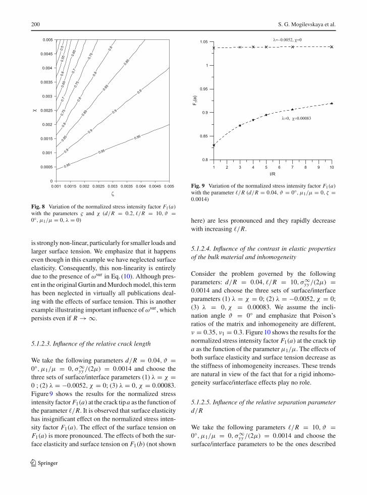
5.1.2.2. Influence of the parameters χ (normalizedsurface tension) and ζ (normalized load)
The form of the governing equations, containing sur-face tension σ0 and the load σ∞
yy , does not allow forthe superposition with respect to the load. This exam-ple is meant to present the quantitative representationof that feature. We choose the following parametersd/R = 0.2, �/R = 10, ϑ = 0◦, µ1/µ = 0, λ = 0.Figure 8 shows the contours of the normalized stressintensity factor F1(a) at the crack tip a as the function ofthe parametersχ and ζ . One can see from the figure thatthe dependence of F1(a)on the surface tension and load
Fig. 7 Variation of thenormalized stress intensityfactor F1(a) with theparameters λ and χ (d/R =0.2, �/R = 10, ϑ =0◦, µ1/µ = 0, ζ = 0.0014)
123
200 S. G. Mogilevskaya et al.
Fig. 8 Variation of the normalized stress intensity factor F1(a)with the parameters ς and χ (d/R = 0.2, �/R = 10, ϑ =0◦, µ1/µ = 0, λ = 0)
is strongly non-linear, particularly for smaller loads andlarger surface tension. We emphasize that it happenseven though in this example we have neglected surfaceelasticity. Consequently, this non-linearity is entirelydue to the presence of ωsur in Eq. (10). Although pres-ent in the original Gurtin and Murdoch model, this termhas been neglected in virtually all publications deal-ing with the effects of surface tension. This is anotherexample illustrating important influence ofωsur, whichpersists even if R → ∞.
5.1.2.3. Influence of the relative crack length
We take the following parameters d/R = 0.04, ϑ =0◦, µ1/µ = 0, σ∞
yy /(2µ) = 0.0014 and choose thethree sets of surface/interface parameters (1) λ = χ =0 ; (2) λ = −0.0052, χ = 0; (3) λ = 0, χ = 0.00083.Figure 9 shows the results for the normalized stressintensity factor F1(a) at the crack tip a as the function ofthe parameter �/R. It is observed that surface elasticityhas insignificant effect on the normalized stress inten-sity factor F1(a). The effect of the surface tension onF1(a) is more pronounced. The effects of both the sur-face elasticity and surface tension on F1(b) (not shown
Fig. 9 Variation of the normalized stress intensity factor F1(a)with the parameter �/R (d/R = 0.04, ϑ = 0◦, µ1/µ = 0, ζ =0.0014)
here) are less pronounced and they rapidly decreasewith increasing �/R.
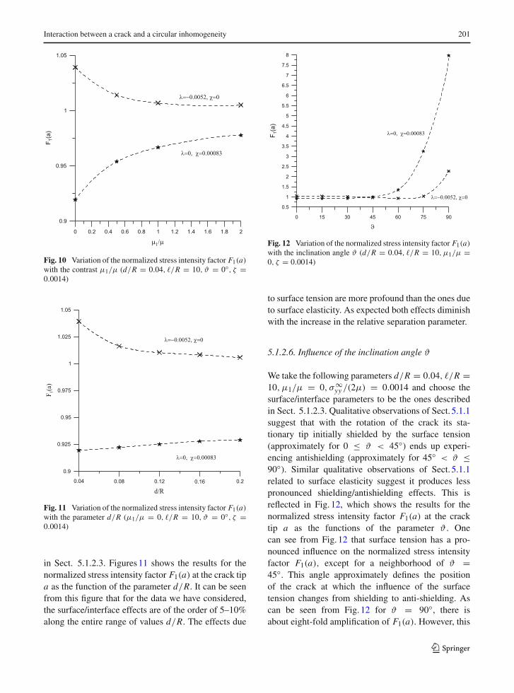
5.1.2.4. Influence of the contrast in elastic propertiesof the bulk material and inhomogeneity
Consider the problem governed by the followingparameters: d/R = 0.04, �/R = 10, σ∞
yy /(2µ) =0.0014 and choose the three sets of surface/interfaceparameters (1) λ = χ = 0; (2) λ = −0.0052, χ = 0;(3) λ = 0, χ = 0.00083. We assume the incli-nation angle ϑ = 0◦ and emphasize that Poison’sratios of the matrix and inhomogeneity are different,ν = 0.35, ν1 = 0.3. Figure 10 shows the results for thenormalized stress intensity factor F1(a) at the crack tipa as the function of the parameter µ1/µ. The effects ofboth surface elasticity and surface tension decrease asthe stiffness of inhomogeneity increases. These trendsare natural in view of the fact that for a rigid inhomo-geneity surface/interface effects play no role.
5.1.2.5. Influence of the relative separation parameterd/R
We take the following parameters �/R = 10, ϑ =0◦, µ1/µ = 0, σ∞
yy /(2µ) = 0.0014 and choose thesurface/interface parameters to be the ones described
123
Interaction between a crack and a circular inhomogeneity 201
Fig. 10 Variation of the normalized stress intensity factor F1(a)with the contrast µ1/µ (d/R = 0.04, �/R = 10, ϑ = 0◦, ζ =0.0014)
Fig. 11 Variation of the normalized stress intensity factor F1(a)with the parameter d/R (µ1/µ = 0, �/R = 10, ϑ = 0◦, ζ =0.0014)
in Sect. 5.1.2.3. Figures 11 shows the results for thenormalized stress intensity factor F1(a) at the crack tipa as the function of the parameter d/R. It can be seenfrom this figure that for the data we have considered,the surface/interface effects are of the order of 5–10%along the entire range of values d/R. The effects due
Fig. 12 Variation of the normalized stress intensity factor F1(a)with the inclination angle ϑ (d/R = 0.04, �/R = 10, µ1/µ =0, ζ = 0.0014)
to surface tension are more profound than the ones dueto surface elasticity. As expected both effects diminishwith the increase in the relative separation parameter.
5.1.2.6. Influence of the inclination angle ϑ
We take the following parameters d/R = 0.04, �/R =10, µ1/µ = 0, σ∞
yy /(2µ) = 0.0014 and choose thesurface/interface parameters to be the ones describedin Sect. 5.1.2.3. Qualitative observations of Sect. 5.1.1suggest that with the rotation of the crack its sta-tionary tip initially shielded by the surface tension(approximately for 0 ≤ ϑ < 45◦) ends up experi-encing antishielding (approximately for 45◦ < ϑ ≤90◦). Similar qualitative observations of Sect. 5.1.1related to surface elasticity suggest it produces lesspronounced shielding/antishielding effects. This isreflected in Fig. 12, which shows the results for thenormalized stress intensity factor F1(a) at the cracktip a as the functions of the parameter ϑ . Onecan see from Fig. 12 that surface tension has a pro-nounced influence on the normalized stress intensityfactor F1(a), except for a neighborhood of ϑ =45◦. This angle approximately defines the positionof the crack at which the influence of the surfacetension changes from shielding to anti-shielding. Ascan be seen from Fig. 12 for ϑ = 90◦, there isabout eight-fold amplification of F1(a). However, this
123
202 S. G. Mogilevskaya et al.
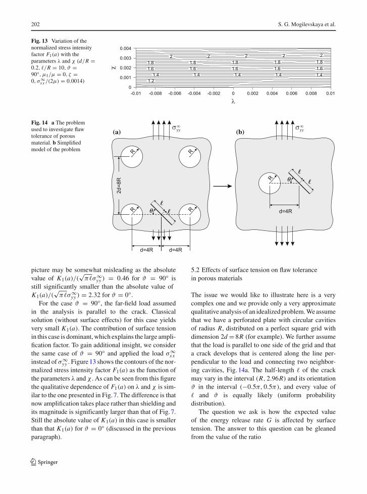
Fig. 13 Variation of thenormalized stress intensityfactor F1(a) with theparameters λ and χ (d/R =0.2, �/R = 10, ϑ =90◦, µ1/µ = 0, ζ =0, σ∞
xx /(2µ) = 0.0014)
Fig. 14 a The problemused to investigate flawtolerance of porousmaterial. b Simplifiedmodel of the problem
(a) (b)
picture may be somewhat misleading as the absolutevalue of K1(a)/(
√π�σ∞
yy ) = 0.46 for ϑ = 90◦ isstill significantly smaller than the absolute value ofK1(a)/(
√π�σ∞
yy ) = 2.32 for ϑ = 0◦.For the case ϑ = 90◦, the far-field load assumed
in the analysis is parallel to the crack. Classicalsolution (without surface effects) for this case yieldsvery small K1(a). The contribution of surface tensionin this case is dominant, which explains the large ampli-fication factor. To gain additional insight, we considerthe same case of ϑ = 90◦ and applied the load σ∞
xxinstead of σ∞
yy . Figure 13 shows the contours of the nor-malized stress intensity factor F1(a) as the function ofthe parameters λ and χ . As can be seen from this figurethe qualitative dependence of F1(a) on λ and χ is sim-ilar to the one presented in Fig. 7. The difference is thatnow amplification takes place rather than shielding andits magnitude is significantly larger than that of Fig. 7.Still the absolute value of K1(a) in this case is smallerthan that K1(a) for ϑ = 0◦ (discussed in the previousparagraph).
5.2 Effects of surface tension on flaw tolerancein porous materials
The issue we would like to illustrate here is a verycomplex one and we provide only a very approximatequalitative analysis of an idealized problem. We assumethat we have a perforated plate with circular cavitiesof radius R, distributed on a perfect square grid withdimension 2d = 8R (for example). We further assumethat the load is parallel to one side of the grid and thata crack develops that is centered along the line per-pendicular to the load and connecting two neighbor-ing cavities, Fig. 14a. The half-length � of the crackmay vary in the interval (R, 2.96R) and its orientationϑ in the interval (−0.5π, 0.5π), and every value of� and ϑ is equally likely (uniform probabilitydistribution).
The question we ask is how the expected valueof the energy release rate G is affected by surfacetension. The answer to this question can be gleanedfrom the value of the ratio
123
Interaction between a crack and a circular inhomogeneity 203
ρ = G
Gclas
with
G = 1 − ν
2µ
π/2∫
−π/2
R∫
R
[(K1(a))
2 + (K2(a))2]
d�dϑ
Gclas = 1 − ν
2µ
π/2∫
−π/2
R∫
R
[(K clas
1 (a))2
+(
K clas2 (a)
)2]
d�dϑ
where the superscript “clas” , relates to the valuesassociated with the corresponding classical problemin which λ = 0, χ = 0. Shielding (antishielding) isassociated with ρ < 1 (ρ > 1).
To analyze the problem shown in Fig. 14a we assumethat distance d = 4R is large enough to neglectinteractions between the cavities, and that the analysiscan be performed using the model shown in Fig. 14b.For the data assumed in the analysis (λ = 0, χ =0.00083, µ1/µ = 0, σ∞
yy /(2µ) = 0.0014) we obtainρ = 0.925, which implies that surface tension is likelyto increase slightly the flaw tolerance of the porousmaterial.
6 Conclusions
In this paper, for the first time, we investigated theproblem of the interaction between a circular inho-mogeneity with surface/interface effects and a straightcrack. Numerical examples are presented to quantifyand discuss the main features of that interaction. Thoseexamples were solved using an effective numericaltechnique that allows one to obtain accurate informa-tion about the elastic fields inside and outside of theinhomogeneity.
The obtained results, reported in Sect. 5, reveal sev-eral characteristics of the problem. It has been shownthat, for some values of the problem parameters, surfacetension may significantly change the stress intensityfactors at the tips of the crack. However, the effects ofsurface elasticity are rather insignificant. We have alsodocumented thatωsur causes the stress intensity factorsto depend non-linearly on surface tension. This feature,as well as the lack of superposition with respect to the
load, is one of the main characteristics of problems withthe surface/interface effects.
While we restricted ourselves to the problem of asingle crack and a single inhomogeneity, the techniqueemployed in this work is applicable to problems withmultiple inhomogeneities and cracks. Such scenariowould be more typical for practical applications, par-ticularly in the analysis of nano-composite materials.Incorporation of surface tension and surface elasticityin crack model is another direction for possible exten-sion of the method.
Appendix 1
System of complex equations
The system of equations that contains the unknowncoefficients for the displacements and displacementdiscontinuities only has the following form:
(i) t ∈ L
4ReA1
R
[µ1/µ
κ1 − 1+ η
µ+ 1
2
]
+∞∑
m=1
mA−m
Rgm+1(t)
[1 + κ
(µ1
µ+ m
η(1)
µ
)]
+∞∑
m=1
(m + 1)A(m+1)
Rg−m(t)
[1 + µ1/µ
κ1+ (m + 1)
η(1)
µ
]
−∞∑
m=2
(m − 1)(m + 1)η(2)
µ
A−(m−1)
Rg−m(t)
−∞∑
m=2
(m − 1)(m + 1)κη(2)
µ
A(m+1)
Rgm(t)
+ i
π
∞∑n=0
dn
b − a
[I1 (st , n)− γ1g2(t)I1 (st , n)
]
− i
π
∞∑n=0
dn
b − a
{[1 + γ1g2(t)
]I1 (st , n)
+2γ1g2(t) (st − st ) I2 (st , n)}
123
204 S. G. Mogilevskaya et al.
= κ + 1
4µ
[σ∞
xx + σ∞yy
−g2(t)(σ∞
yy − σ∞xx − 2iσ∞
xy
)]− σ0
µR(25)
(i) t ∈ Lc
2
γ1g2(t)Re
A1
R[1 − (κ − 1)
(µ1/µ
κ1 − 1+ η
µ
)]
−∞∑
m=1
mA−m
Rgm+1(t)
[1 − µ1
µ− m
η(1)
µ
]
+ 1
γ1
∞∑m=1
(m + 1)A(m+1)
Rgm(t)
×{[
1 − κ
κ1
µ1
µ− κ (m + 1)
η(1)
µ
− (m − 1) (m + 1)η(2)
µ
]g2(t)
+ (m − 1)η(2)
µ
[−γ1 + mg−1(t)g(t)
]}
− 1
γ1
∞∑m=1
mA−m
Rgm+1(t)
×{ [γ1 − (m + 1) g−1(t)g(t)
+ (m + 2) g2(t)] [
1 − µ1
µ− m
η(1)
µ
]
+κ (m + 2)η(2)
µg2(t)
}
−∞∑
m=2
(m − 1)(m + 1)
× η(2)
µ
A(m+1)
Rgm(t)
+2i∞∑
n=0
dn
b − a(n + 1)Un (st )
= κ + 1
4µ
[2σ c(t)−
(σ∞
xx + σ∞yy
)
− 1
γ1
(σ∞
yy − σ∞xx − 2iσ∞
xy
) ]
+κ − 1
2γ1
σ0
µRg2(t) (26)
where
η = (2µ0 + λ0) / (4R) ,
η(1) = η + 0.25σ0/R, η(2) = η − 0.25σ0/R
I1 (st , n) =1∫
−1
√1 − s2Un (s) ds
(s − st )2
= π (n + 1)
(st −
√s2
t − 1
)n+1
√s2
t − 1(27)
I2 (st , n) =1∫
−1
√1 − s2Un (s) ds
(s − st )3
= −1
2I1 (st , n)
⎡⎣ n + 1√
s2t − 1
+ st
s2t − 1
⎤⎦
and st = (2t − a − b) / (b − a) , γ1 = (b − a) /(b − a
).
To solve the system (25), (26) and define theunknown coefficients one needs to truncate the series.The displacements and the displacement discontinu-ities should be truncated as follows:
σ inh(τ ) =Mh∑
m=2
Binh−m gm(τ )+Mh∑
m=0
Binhm g−m(τ )
σmat(τ ) =Mh∑
m=2
Bmat−m gm(τ )+Mh∑
m=0
Bmatm g−m(τ )
u(τ ) =Mh−1∑m=1
A−m gm(τ )+Mh+1∑m=1
Am g−m(τ )
uc(s) =√
1 − s2Mc∑
n=0
dnUn (s) (28)
Reduction to a linear algebraic system
A system of linear algebraic equations can be obtainedby using a Galerkin (weighted residual) method. Mul-tiplying both parts of Eq. (25) by functions g p(t) (p =−Mh +1, . . .−1, 1, . . .Mh +1) and integrating alongthe boundary L , one obtains the system of followingequations:
123
Interaction between a crack and a circular inhomogeneity 205
[1 + κ
(µ1
µ+ p
η(1)
µ
)]A−p
R
− (p + 2) κη(2)
µ
A(p+2)
R
+iγ p1
Mc∑n=0
{− dn
b − aG pn
(szc
)
− dn
b − a
[− γ1 (p + 2)G(p+2)n
(szc
)
+pG pn(szc
)
+ (p + 1)szc − szc
γ2G(p+1)n
(szc
)]}
= −κ + 1
4µ
(σ∞
yy − σ∞xx
−2iσ∞xy
)δp1, p = 1, . . . ,Mh − 1
× 4
[µ1/µ
κ1 − 1+ η
µ+ 1
2
]Re
A1
R
+iMc∑
n=0
[dn
b − aG1n
(szc
)
− dn
b − aG1n
(szc
) ]
= κ + 1
4µ
(σ∞
yy + σ∞xx
)
− σ0
µR
[1 + µ1/µ
κ1+ p
η(1)
µ
]Ap
R
− (p − 2)η(2)
µ
A−(p−2)
R
+iMc∑
n=0
dn
b − aG pn
(szc
)
= 0, p = 2, . . . ,Mh + 1 (29)
where γ2 = 2R/(b − a), δpq is the Kronecker delta,and G pn (z) is defined as
G pn (z) = γp−1
21
π
1∫
−1
√1 − s2Un (s)
(s − z)p+1 (30)
The integral involved in (30) is evaluated analyti-cally using recursive relations, as explained in Wang2004.
Similarly, multiplying both parts of Eq. (26) by func-
tions√
1 − s2t Uq (st ) (q = 0, . . . ,Mc) and integrating
along the boundary Lc, one obtains the following equa-tion (q = 0, . . . ,Mc):
2ReA1
R
[1 − (κ − 1)
(µ1/µ
κ1 − 1+ η
µ
)]G1q
(szc
)
− 1
γ1
Mh−1∑m=1
A−m
Rm
[1 − µ1
µ− m
η(1)
µ
]Gmq
(szc
)
+Mh∑
m=1
γm1 (m + 1)
Am+1
R
{[1 − κ
κ1
µ1
µ
−κ (m + 1)η(1)
µ
−(m − 1)(m + 1)η(2)
µ
]Gm+1q
(szc
)
+(m − 1)η(2)
µ
[m − 1
γ1Gm−1q
(szc
)
+mszc − szc
γ 2Gmq
(szc
)]}
−Mh−1∑m=1
γm+11 m
A−m
R
⎧⎨⎩[− m
γ1Gmq
(szc
)
−(m + 1)szc − szc
γ 2Gm+1q
(szc
)
+ (m + 2)Gm+2q(szc
)] [1 − µ1
µ− m
η(1)
µ
]
+κ(m + 2)η(2)
µGm+2q
(szc
)}
−Mh∑
m=1
(m − 1)(m + 1)
γ1
η(2)
µ
Am+1
RGm−1q
(szc
)
+i(q + 1)dq
b − a
1
γ 2γ2
= κ + 1
8µ
1
γ 2γ2
[2σ c(t)−
(σ∞
xx + σ∞yy
)
− 1
γ1
(σ∞
yy − σ∞xx − 2iσ∞
xy
) ]δ0q
+(κ − 1)σ0
2µRG1q
(szc
)(31)
Separating real and imaginary parts in Eq. (29) and(31), we get the system of 4Mh + 2Mc + 1 real lin-ear algebraic equations, where the transposed vector ofunknowns is[
ReA−(Mh−1), ImA−(Mh−1), . . . ,
ReA−1, ImA−1,ReA1,ReA2, ImA2, . . . ,
ReA(Mh+1), ImA(Mh+1),Red0, Imd0, . . . ,
RedMc , ImdMc
](32)
123
206 S. G. Mogilevskaya et al.
Appendix 2
Calculations of the displacements, stresses, strains andstress intensity factors in the system
After substituting expressions (28) into formulae (13),(14) and (15), all integrals can be evaluated analyti-cally. The final expressions for the potentials for thedisc (13) and the hole (14) are the same as the cor-responding expressions in Mogilevskaya et al. (2008).The final expressions for terms involved in Eq. (15) areas follows
ϕc(z) = − iµ
κ + 1
Mc∑n=0
dn I0(sz, n)+ fϕ(σc)
ψc(z) = iµ
κ + 1
Mc∑n=0
{dn I0(sz, n)
+ 2
b − a
[γ1(z − a)+ a
]dn I1(sz, n)
}
+ fψ(σc) (33)
where
I0(sz, n) = 1
π
1∫
−1
√1 − s2Un(s)
s − z
= −(
sz −√
s2z − 1
)n+1
(34)
and the functions fϕ(σ c), fψ(σ c) are known after oneevaluates the integrals from Eq. (15) that contain σ c.
Resulting potentials define the stresses in the matrixand an inhomogeneity in unique way, as the displace-ments are defined by the potentials up to some addi-tional terms. These terms correspond to rigid bodytranslations and rotations, and are found the followingprocedure similar to one described in Mogilevskayaet al. (2008).
The stress intensity factors at the tips of the crackcan be calculated from the coefficients of the Cheby-shev polynomials by using expressions (17) and (21).The final expressions are the following (Wang et al.2001):
(K1 − i K2)a
= −2√
2πµi
κ + 1
exp(−iθ1/2)√b − a
Mc∑n=0
(−1)n(n + 1)dn
(K1 − i K2)b
= −2√
2πµi
κ + 1
exp(−iθ2/2)√b − a
Mc∑n=0
(n + 1)dn (35)
References
Chen T, Dvorak GJ, Yu CC (2007) Size-dependent elastic prop-erties of unidirectional nano-composites with interfacestresses. Acta Mech 188:39–54
Chuang T-J (1987) Effect of surface tension on the toughness ofglass. J Am Ceram Soc 70:160–164
Duan HL, Wang J, Huang ZP, Luo ZY (2005a) Stress concentra-tion tensors of inhomogeneities with interface effects. MechMater 37:723–736
Duan HL, Wang J, Huang ZP, Karihaloo BL (2005b) Eshelbyformalism for nano-inhomogeneities. Proc R Soc LonA461:3335–3353
Duan HL, Wang J, Huang ZP, Karihaloo BL (2005c) Size-dependent effective elastic constants of solids containingnano-inhomogeneoties with interface stress. J Mech PhysSolids 53:1574–1596
Duan HL, Wang J, Karihaloo BL, Huang ZP (2006) Nanoporousmaterials can be made stiffer that non-porous counterpartsby surface modification. Acta Mater 54:2983–2990
Duan HL, Yi X, Huang ZP, Wang J (2007) A united schemefor prediction of effective moduli of multiphase compositeswith interface effects. Part I: theoretical framework. MechMater 39:81–93
Fang QH, Liu YW (2006) Size-dependent interaction betweenan edge dislocation and a nanoscale inhomogeneity withinterface effects. Acta Mater 54:4213–4220
Fang QH, Li B, Liu YW (2007) Interaction between edge dislo-cations and a circular hole with surface stress. Phys Stat SolB 244:2576–2588
Gurtin ME, Murdoch AI (1975) A continuum theory of elasticmaterial surfaces. Arch Ration Mech Anal 57:291–323
Gurtin ME, Murdoch AI (1978) Surface stress in solids. Int JSolids Struct 14:431–440
He LH, Li ZR (2006) Impact of surface stress on stress concen-tration. Int J Solids Struct 43:6208–6219
Helsing J, Jonsson A (2002) On the accuracy of benchmarktables and graphical results in the applied mechanics lit-erature. J Appl Mech 69:80–90
Huang ZP, Wang J (2006) A theory of hyperelasticity of multi-phase media with surface/interface energy effect. ActaMech 182:195–210
Lim CW, Li ZR, He LH (2006) Size-dependent, non-uniformelastic field inside a nano-scale spherical inclusion due tointerface stress. Int J Solids Struct 43:5055–5065
Linkov AM (2002) Boundary integral equations in elasticity the-ory. Kluwer, Dordrecht
Linkov AM, Mogilevskaya SG (1998) Complex hypersingularBEM in plane elasticity problems. In: Sladek V, Sladek J(eds) Singular integrals in boundary element method. Com-putational Mechanics Publication, Southampton pp 299–364
Mi C, Kouris DA (2006) Nanoparticles under the influence ofsurface/interface elasticity. Mech Mater Struct 1:763–791
123
Interaction between a crack and a circular inhomogeneity 207
Miller RE, Shenoy VB (2000) Size-dependent elastic propertiesof nanosized structural elements. Nanotechnology 11:139–147
Mogilevskaya SG, Crouch SL (2001) A Galerkin boundary inte-gral method for multiple circular elastic inclusions. Int JNumer Methods Eng 52:1069–1106
Mogilevskaya SG (1996) The universal algorithm based on com-plex hypersingular integral equation to solve plane elasticityproblems. Comput Mech 18:127–138
Mogilevskaya SG, Crouch SL, Stolarski HK (2008) Multipleinteracting circular nano-inhomogeneities with sur-face/interface effects. J Mech Phys Solids 56:2327–2928
Mogilevskaya SG, Linkov AM (1998) Complex fundamentalsolutions and complex variables boundary element methodin elasticity. Comput Mech 22:88–92
Muskhelishvili NI (1959) Some basic problems of the mathe-matical theory of elasticity. Noordhoff, Groningen
Oh E-S, Walton JR, Slattery JC (2006) A theory of fracture basedupon an extension of continuum machanics to the nanoscale.J Appl Mech 73:792–798
Phan AV, Gray LJ, Kaplan T (2007) On some benchmark resultsfor the interaction of a crack with a circular inclusion. JAppl Mech 74:1282–1284
Rajapakse YDS (1975) Surface energy and surface tension atholes and cracks. Int J Fract 11:57–69
Sharma P, Ganti S (2002) Interfacial elasticity corrections tosize-dependent strain-state of embedded quantum dots.Phys Stat Sol 234:R10–R12
Sharma P, Ganti S (2004) Size-dependent Eshelby’s tensor forembedded nano-inclusions incorporating surface/interfaceenergies. J Appl Mech 71:663–671
Sharma P, Ganti S, Bhate N (2003) Effect of surfaces on the size-dependent elastic state of nano-inhomogeneities. Appl PhysLett 82:535–537
Tian L, Rajapakse RKND (2007a) Analytical solution for size-dependent elastic field of a nanoscale circular inhomogene-ity. J Appl Mech 74:568–574
Tian L, Rajapakse RKND (2007b) Elastic field of an isotropicmatrix with a nanoscale elliptical inhomogeneity. Int J Sol-ids Struct 44:7988–8005
Tian L, Rajapakse RKND (2007c) Finite element modellingof nanoscale inhomogeneities in an elastic matrix. CompMater Sci 41:44–53
Thomson R, Chuang T-J, Lin I-H (1986) The role of surfacestress in fracture. Acta Metall 34:1133–1143
Wang J (2004) Numerical modeling of elastic materials withinclusions, holes, and cracks. Ph.D. Thesis. University ofMinnesota, Minneapolis
Wang J, Mogilevskaya SG, Crouch SL (2001) A Galerkinboundary integral method for nonhomogeneous materialswith cracks. In: Elsworth D, Tinucci JP, Heasley KA (eds)Rock mechanics in the national interest. Balkema, Rotter-dam pp 1453–1460
Wang J, Mogilevskaya SG, Crouch SL (2003) Benchmarkresults for the problem of interaction between a crack anda circular inclusion. J Appl Mech 70:619–621
Wu CH (1999) The effect of surface stress on the configura-tional equilibrium of voids and cracks. J Mech Phys Solids47:2469–2492
Wu CH, Wang ML (2001) Configurational equilibrium of cir-cular-arc cracks with surface stress. Int J Solids Struct38:4279–4292
Yang FQ (2004) Size-dependent effective modulus of elasticcomposite materials: spherical nanocavities at dilute con-centrations. J Appl Phys 95:3516–3520
Zhang WX, Wang TJ (2007) Effect of surface energy on the yieldstrength of nanoporous materials. Appl Phys Lett 90, Art.No. 063104
123