Embed Size (px)
Citation preview
Internship Final Report
Host Company:
Benaim (Malaysia)
Prepared by:
Mohammad Reza Saiedi
ID: 6211, Civil Engineering
July 2006
Internship Final Report M. R. Saiedi
ii
ACKNOWLEDGEMENTS
I would like to thank the various people involved in making this internship a success:
First and foremost, I would like to thank my supervisor, Mr. Akram Malik
(Director) who found time in a very busy schedule to give me new engineering tasks, monitor
my progress and answer my questions. His passion for civil engineering and bridges has
really inspired me. I am also deeply grateful for his advice, encouragement and patience
throughout the duration of the internship. The support he has given me as an expatriate in a
predominantly Malaysian environment has been greatly appreciated too.
Second, I would like to thank Mr. Afshin Forouzani (Director) for his backing,
attention and time. I have very much benefited from his professional and personal advice.
Third, I would like to express my gratitude to Lee Hong Yong (Sam, Engineer), Goh
Wei Yoon (Engineer), Mak Kok You (Associate) and Wong Chong Ling (Associate) for
sharing their technical knowledge with me in answering my many questions.
Fourth, I would like to thank Irene Sen (Administrative Manager), Carol Manuel
(Associate) and Tan Kwan Loong (Trainee) for their warm friendship.
Fifth, I am sincerely grateful to my beloved parents, Dr. Shayesteh Jahanfar and Dr.
Saied Saiedi, for their financial and emotional support during my stay in Kuala Lumpur.
Finally, I would like to express my thanks to my lecturer, Assoc. Prof. Dr. Nasir
Shafiq, for travelling from far away to attend both industrial visits, for taking the time to
evaluate this report, and for his advice regarding my final year project, study and career
opportunities.
Internship Final Report M. R. Saiedi
iii
TABLE OF CONTENTS
EXECUTIVE SUMMARY ..................................................................................................1
INTRODUCTION................................................................................................................2
PROJECTS...........................................................................................................................4
THE JAMARAT BRIDGE IN MINA ........................................................................................5
ACTIVITIES ........................................................................................................................8
ENGINEERING WORK..................................................................................................8
STRUCTURAL ANALYSIS ..............................................................................................8
Modelled Link Slab in STAAD...................................................................................8
Studied Effects of Extra Surfacing on a Bridge in ENCAD .......................................10
Calculated and Combined All Loads on a Bridge ......................................................12
CONSTRUCTION SEQUENCING................................................................................14
Sequenced Construction of a Segmental Box Girder .................................................14
REINFORCED CONCRETE DESIGN ..........................................................................16
Designed Footings for Stacking Precast Segments ....................................................16
Designed Irregular Bridge Pilecap.............................................................................17
QUANTITY SURVEYING .............................................................................................19
Assessed a Bridge in Terms of Value Engineering ....................................................19
Quantified Steel and Concrete in Tunnel U-Walls .....................................................21
SOFTWARE..................................................................................................................22
Worked with AutoCAD ............................................................................................23
MISCELLANEOUS.......................................................................................................24
Produced Bar Bending Schedules..............................................................................24
Prepared Bridge-Related Masters Research Proposal.................................................24
Read Civil Engineering Publications .........................................................................25
SITE VISITS ...................................................................................................................27
Visited Balakong Interchange, KL: Ramps................................................................27
Visited Balakong Interchange, KL: Prestressing........................................................28
Visited New Pantai Highway, KL .............................................................................30
ADMINISTRATIVE WORK .........................................................................................32
LESSONS & EXPERIENCES...........................................................................................36
Technical Lessons.....................................................................................................36
Non-Technical Lessons.............................................................................................38
Miscellaneous Skills .................................................................................................40
Problems and Challenges ..........................................................................................42
CONCLUSION & RECOMMENDATIONS ....................................................................43
APPENDICES ....................................................................................................................44
Internship Final Report M. R. Saiedi
1
EXECUTIVE SUMMARY
I spent my internship at British bridge consultant, Benaim (Malaysia) as a civil
engineering trainee. The internship started in December 2005 and ended in July 2006.
I was mainly occupied with the "Jamarat Bridge in Mina" project, a new $1.9bn four-
storey mega-structure in Saudi Arabia. I also had some involvement in other projects
including two bridges in Singapore and Malaysia and a tunnel in Qatar.
My internship activities can be broadly divided into engineering work, site visits and
administrative work. On the engineering front, I carried out tasks in various key areas,
namely structural analysis, construction sequencing, reinforced concrete design, quantity
surveying, software, etc. I had three valuable visits to construction sites in Kuala Lumpur,
where I observed various bridge components, the construction of reinforced concrete
members, and prestressing operations. I also had administrative responsibilities involving
filing, checking, and auditing drawings.
The internship taught me a great deal. Technically, I learnt about bridge engineering
and relevant site operations, drawings, software, design codes and materials. At the same
time, I was exposed to project management, administration and teamwork. I also experienced
office culture and improved my social and communicational skills.
Despite some challenges, the internship was a great success. I grew as a civil engineer
in all respects and it very much prepared me for life after graduation.
Internship Final Report M. R. Saiedi
2
INTRODUCTION
This report presents the details of my internship experience at Benaim (Malaysia) as a
trainee civil engineer from December 2005 to July 2006. As background for your reading of
this report, I have included: (1) the internship objectives, (2) a brief description of the host
company, (3) the scope of my activities, and (4) an overview of the report format.
Internship Objectives
The purpose of the internship is to expose UTP students to the world of
work so that they can relate theoretical knowledge with application in industry.
They will also develop skills in work ethics, communication and management.
And it will expose students to potential employers too.
Description of Host Company
The Benaim group was established in
1980 by Robert Benaim and was sold to
the senior management under a
friendly management-buyout in 2000.
Benaim has an established reputation
for producing elegant and economical
designs, specialising in high-quality structures across the spectrum of civil,
structural and geotechnical
engineering.
The company is at the forefront of the
latest techniques in construction and is
committed to finding the best possible
designs for projects ranging from major
viaducts to light weight building
structures.
We are committed to working in
partnership with our clients and
delivering innovative solutions to their
individual needs. We have extensive
in-house computing facilities including
computer-aided design and drafting
and three-dimensional modelling.
The group has offices in London, Bath,
Hong Kong, Kuala Lumpur and
Singapore.
Benaim's vision is to be the Consultant
of choice, designing creative solutions,
adding value and making the complex
simple.
Internship Final Report M. R. Saiedi
3
Benaim (Malaysia) Sdn Bhd
Project Management, Construction Technology and Value Management
Units 802 & 803, Level 8, Uptown 2
2 Jalan SS 21/37, Damansara Uptown
47400 Petaling Jaya, Selangor Darul Ehsan
Telephone +603 7725 9021 Facsimile +603 7722 5794
Email [email protected]
See Appendix A for Benaim’s company profile concerning bridges.
Visit http://www.benaimgroup.com for more details.
Scope of Activities
My internship activities included:
• Engineering Work
1. Structural Analysis
2. Construction Sequencing
3. Reinforced Concrete Design
4. Quantity Surveying
5. Software
6. Miscellaneous
• Site Visits
• Administrative Work
Report Format
This report includes four main sections:
1. Projects
2. Activities
3. Lessons and Experiences
4. Conclusion and Recommendations

Internship Final Report M. R. Saiedi
4
PROJECTS
Among the several jobs that Benaim (Malaysia) had at the time, I was involved in four
projects (Table 1). Two are in the Middle East, home to many emerging construction
projects, and the other two are in Southeast Asia. The Jamarat Bridge in Mina is the project
I dealt with the most. An overview of this project follows on the next page.
Table 1: Projects I was involved in
NO. PROJECT LOCATION
1 Jamarat Bridge in Mina Saudi Arabia
2 Midfield Access Road Tunnel,
New Doha International Airport
Qatar
3 KL-Putrajaya Highway Malaysia
4 Pasir Panjang Semi-Expressway Singapore
Midfield Access Road Tunnel
This tunnel in the New Doha International Airport is located beneath the West runway
and taxiways. The tunnel incorporates two three-lane roadways separated by a central
partition. The structure consists of a two-cell buried concrete tunnel segment transitioning to
U-wall and retaining wall approaches at each end.
KL-Putrajaya Highway
The mainline portion comprises elevated dual three-lane carriageways and the ramps
comprise two-lane single carriageways. The bridge deck consists of precast T-beams with
cast-in-situ slabs on top. Span lengths vary between 20m and 50m. The T-beams are
supported on prestressed precast segmental crossheads over reinforced concrete columns.
Foundations are generally hand-dug caissons or bored piles.
Pasir Panjang Semi-Expressway
The viaduct consists of a separated pair of three-lane prestressed concrete box girders
elevated above existing road. Both Eastbound and Westbound decks are supported off
crossheads that cantilever out of the columns. The two decks are supported by a row of single
columns located at the central reserve of the existing road. The deck is monolithic with the
columns, which are supported on bored pile foundations. See Appendix A for more details.

Internship Final Report M. R. Saiedi
5
The Jamarat Bridge in Mina
Background Information
Every year, millions of Muslims come to Mecca, Saudi Arabia to perform the Hajj.
One of the central rituals is the symbolic stoning of three pillars at Mina. During the four-day
pilgrimage, up to 3 million pilgrims gather on a two-tier elevated structure known as the
Jamarat Bridge to throw their stones. See Figure 1.
Figure 1: The existing Jamarat structure
Fatal Crowd Crushes
The sheer number of people converging on the site within the five to six hours allowed
to perform the rite has led to severe overcrowding. Today it is estimated that the bridge holds
15-20 % more pilgrims during the rite than it is designed to. Fatal crowd crushes have
occurred regularly in recent years. In January 2006, 363 pilgrims died at the eastern entrance.
See Activities: Engineering Work: Miscellaneous: Read Civil Engineering Publications:
Figure 15 for the news story.
The New Structure
A new $1.9bn four-tier bridge is being designed to replace the existing structure
(Figure 2). It will help ease the flow of pilgrims and is designed to prevent a repeat of the
tragedies that have blighted the event. Construction is expected to be complete within two
years.
Internship Final Report M. R. Saiedi
6
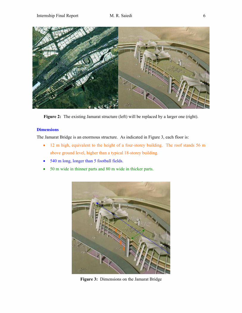
Figure 2: The existing Jamarat structure (left) will be replaced by a larger one (right).
Dimensions
The Jamarat Bridge is an enormous structure. As indicated in Figure 3, each floor is:
• 12 m high, equivalent to the height of a four-storey building. The roof stands 56 m
above ground level, higher than a typical 18-storey building.
• 540 m long, longer than 5 football fields.
• 50 m wide in thinner parts and 80 m wide in thicker parts.
Figure 3: Dimensions on the Jamarat Bridge
Internship Final Report M. R. Saiedi
7
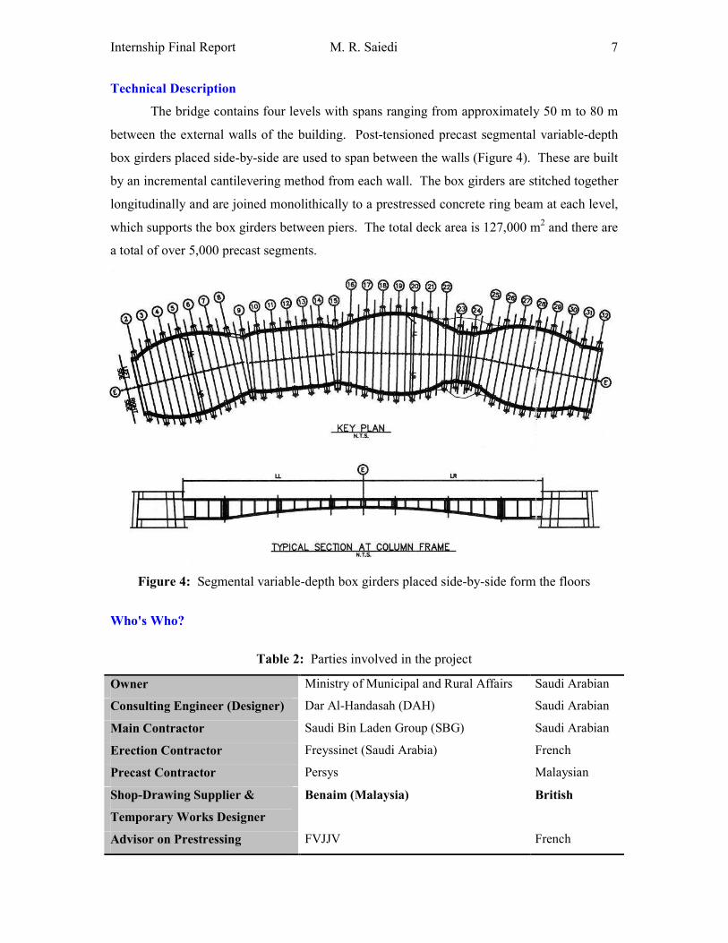
Technical Description
The bridge contains four levels with spans ranging from approximately 50 m to 80 m
between the external walls of the building. Post-tensioned precast segmental variable-depth
box girders placed side-by-side are used to span between the walls (Figure 4). These are built
by an incremental cantilevering method from each wall. The box girders are stitched together
longitudinally and are joined monolithically to a prestressed concrete ring beam at each level,
which supports the box girders between piers. The total deck area is 127,000 m2 and there are
a total of over 5,000 precast segments.
Figure 4: Segmental variable-depth box girders placed side-by-side form the floors
Who's Who?
Table 2: Parties involved in the project
Owner Ministry of Municipal and Rural Affairs Saudi Arabian
Consulting Engineer (Designer) Dar Al-Handasah (DAH) Saudi Arabian
Main Contractor Saudi Bin Laden Group (SBG) Saudi Arabian
Erection Contractor Freyssinet (Saudi Arabia) French
Precast Contractor Persys Malaysian
Shop-Drawing Supplier &
Temporary Works Designer
Benaim (Malaysia) British
Advisor on Prestressing FVJJV French
Internship Final Report M. R. Saiedi
8
ACTIVITIES
ENGINEERING WORK
STRUCTURAL ANALYSIS
Modelled Link Slab in STAAD
(See Logbook: Weeks 19 & 20 for details.)
Introduction
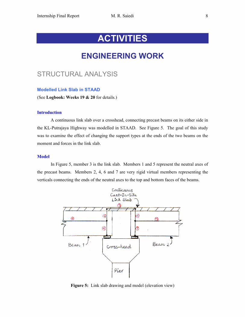
A continuous link slab over a crosshead, connecting precast beams on its either side in
the KL-Putrajaya Highway was modelled in STAAD. See Figure 5. The goal of this study
was to examine the effect of changing the support types at the ends of the two beams on the
moment and forces in the link slab.
Model
In Figure 5, member 3 is the link slab. Members 1 and 5 represent the neutral axes of
the precast beams. Members 2, 4, 6 and 7 are very rigid virtual members representing the
verticals connecting the ends of the neutral axes to the top and bottom faces of the beams.
Figure 5: Link slab drawing and model (elevation view)
Internship Final Report M. R. Saiedi
9
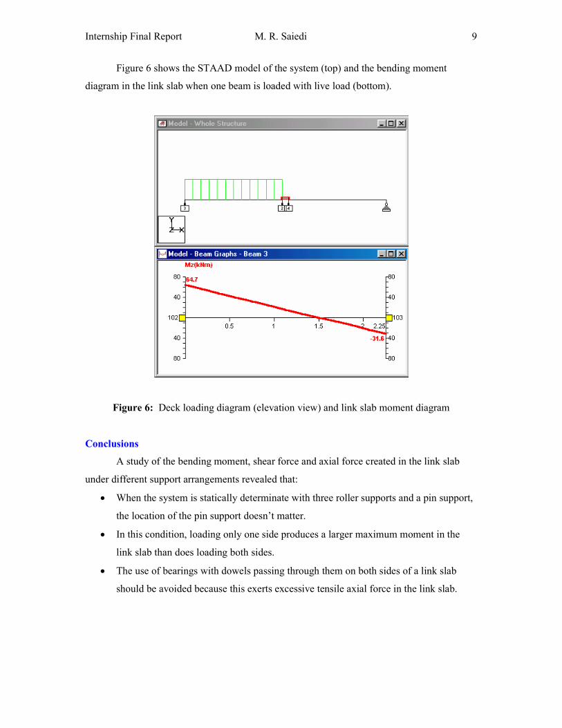
Figure 6 shows the STAAD model of the system (top) and the bending moment
diagram in the link slab when one beam is loaded with live load (bottom).
Figure 6: Deck loading diagram (elevation view) and link slab moment diagram
Conclusions
A study of the bending moment, shear force and axial force created in the link slab
under different support arrangements revealed that:
• When the system is statically determinate with three roller supports and a pin support,
the location of the pin support doesn’t matter.
• In this condition, loading only one side produces a larger maximum moment in the
link slab than does loading both sides.
• The use of bearings with dowels passing through them on both sides of a link slab
should be avoided because this exerts excessive tensile axial force in the link slab.
Internship Final Report M. R. Saiedi
10
Studied Effects of Extra Surfacing on a Bridge in ENCAD
(See Logbook: Week 7 for details.)
Introduction
The Pasir Panjang Semi-Expressway runs east west along the south of Singapore. Due
to errors in precasting the box segments, the deck's as-built level is lower than the proposed
level in some places, i.e. the bridge is drooping below the intended elevation. To ensure a
smooth ride for vehicles on the expressway, surfacing is made thicker at these points so as to
bring the road surface up to ideal height. Too thick a surface, however, could make the deck
dangerously heavy. To avoid this, the design surface elevation may be lowered at some
points.
Surfacing Thickness
Measurements of the as-built level had been made in intervals of 5 metres, whereas
design elevation was known every 3 metres. Therefore, the writer computed design
elevations at points of as-built measurement by interpolation. Next, the proposed finished
level at each point minus the actual deck level gave the thickness of surfacing required to
correct the deck level. Then, the plot of surfacing thickness vs. chainage was drawn for both
eastbound and westbound roads, on which the location of piers were also marked. The plot
indicated surfacing to be thickest at mid-spans.
Structural Analysis
Using the surfacing thickness values obtained at every 5 metres, the average surfacing
thickness was computed on each span. This, together with the span length, gave the average
loading on each span.
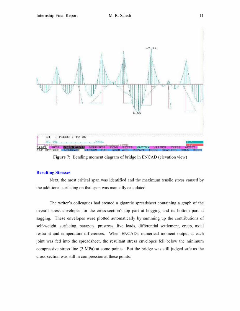
The loads of the most critical spans (viaducts 2-5) were entered into ENCAD, a
structural analysis program. It analyzed the structure and plotted the axial force, shear force,
and bending moment diagrams (Figure 7) as well as the bridge's deflected shape. Careful
study of these graphs gave the writer great insights into the inner workings of multi-span
bridges. ENCAD also expressed the axial force, shear force, and bending moment values at
each joint numerically.
Internship Final Report M. R. Saiedi
11
Figure 7: Bending moment diagram of bridge in ENCAD (elevation view)
Resulting Stresses
Next, the most critical span was identified and the maximum tensile stress caused by
the additional surfacing on that span was manually calculated.
The writer’s colleagues had created a gigantic spreadsheet containing a graph of the
overall stress envelopes for the cross-section's top part at hogging and its bottom part at
sagging. These envelopes were plotted automatically by summing up the contributions of
self-weight, surfacing, parapets, prestress, live loads, differential settlement, creep, axial
restraint and temperature differences. When ENCAD's numerical moment output at each
joint was fed into the spreadsheet, the resultant stress envelopes fell below the minimum
compressive stress line (2 MPa) at some points. But the bridge was still judged safe as the
cross-section was still in compression at these points.
Internship Final Report M. R. Saiedi
12
Calculated and Combined All Loads on a Bridge
(See Logbook: Weeks 26 & 27 for details.)
Introduction
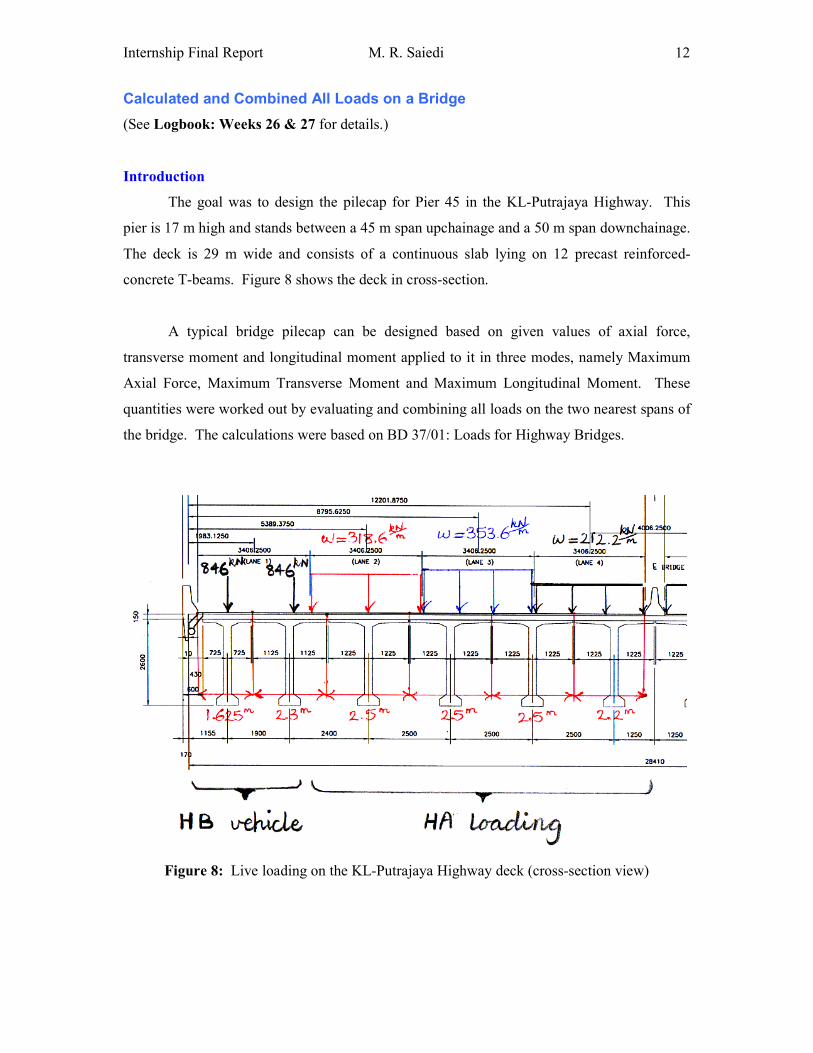
The goal was to design the pilecap for Pier 45 in the KL-Putrajaya Highway. This
pier is 17 m high and stands between a 45 m span upchainage and a 50 m span downchainage.
The deck is 29 m wide and consists of a continuous slab lying on 12 precast reinforced-
concrete T-beams. Figure 8 shows the deck in cross-section.
A typical bridge pilecap can be designed based on given values of axial force,
transverse moment and longitudinal moment applied to it in three modes, namely Maximum
Axial Force, Maximum Transverse Moment and Maximum Longitudinal Moment. These
quantities were worked out by evaluating and combining all loads on the two nearest spans of
the bridge. The calculations were based on BD 37/01: Loads for Highway Bridges.
Figure 8: Live loading on the KL-Putrajaya Highway deck (cross-section view)
Internship Final Report M. R. Saiedi
13
Calculated Nominal Loads
Nominal loads were calculated individually and keyed into a special spreadsheet.
Starting from the pilecap and moving upwards, these loads are:
• The weight of the pilecap and the soil on top of it
• The effects of the pier resting on the pilecap, including:
o The weight of the pier itself and the crosshead sitting on the pier
o The forces that the superstructure imposes on the bearings lying on the
crosshead, including:
� Horizontal forces due to creep & shrinkage and changes in temperature
� Vertical forces due to dead loads (i.e. beams, diaphragms, slab,
surfacing, median, parapets and noise barriers) and live loads (i.e. HA
alone and HA+HB)
Combined Nominal Loads
Having obtained the nominal loads, they had to be combined to get the total axial load,
total transverse moment and total longitudinal moment at the pier base. The writer’s
spreadsheet automatically does this.
Compared Combinations
The most critical set of results had to be found for each of the 'Maximum Axial Force',
'Maximum Transverse Moment' and 'Maximum Longitudinal Moment' spreadsheets among
numerous possible combinations. The following were considered:
• 2 cases of live load: HA alone and HA + HB
• 2 load combinations: Combination 1 and Combination 3.
• 2 limit states: Ultimate (ULS) and Serviceability (SLS)
There were now a total of 2 * 2 * 2 = 8 combinations for each spreadsheet. In the
spreadsheets, combinations influence the results via changing values of γfL and γf3, while
nominal load values are left intact.
The results of all load combinations were summarized and the most critical
combination was found in each load-case. These were the numbers that would be used for
pilecap design.
Internship Final Report M. R. Saiedi
14
CONSTRUCTION SEQUENCING
Sequenced Construction of a Segmental Box Girder
(See Logbook: Week 12 for details.)
Introduction
In the Jamarat Bridge, segments are erected by the balanced cantilever technique, with
a special lifting frame fixed to the deck. The first precast segment is lifted into position next
to the completed in-situ segment and its alignment is adjusted using jacks. Subsequent
segments are transported into position and lifted on one side of the column, being fixed to it
by epoxy, temporary prestress and cantilever prestressing tendons. Further segments are
positioned with erection progressing out from the column. When the cantilever reaches mid-
span it is connected up to the opposing cantilever from the opposite column by an in-situ
concrete stitch. Continuity prestressing tendons are installed along the length of the span and
across the stitch to complete the connection.
Conditions
As simple as it may seem, the exact sequence of construction requires thorough
planning in order to meet the following conditions:
1. There can be no tension at any joint at any stage of the erection process.
2. During the open time of the epoxy, the temporary prestress should apply a controlled
amount of compressive stress, to ensure that the joint thickness is constant throughout.
In order to satisfy the above conditions, we must carefully choose the right amount
and sequence of temporary prestress.
Benaim’s Solution
To find the best construction sequence, Benaim use a cleverly designed Excel
spreadsheet that automates a great deal of calculation. Formulas translate loads into moments
and, based on section properties, translate moments into stresses.
Every joint has its own worksheet that monitors its stresses throughout the entire
erection process. Stresses are controlled only at the top and bottom extremities as they mark
the limits of the range of stresses in a cross-section.
Internship Final Report M. R. Saiedi
15
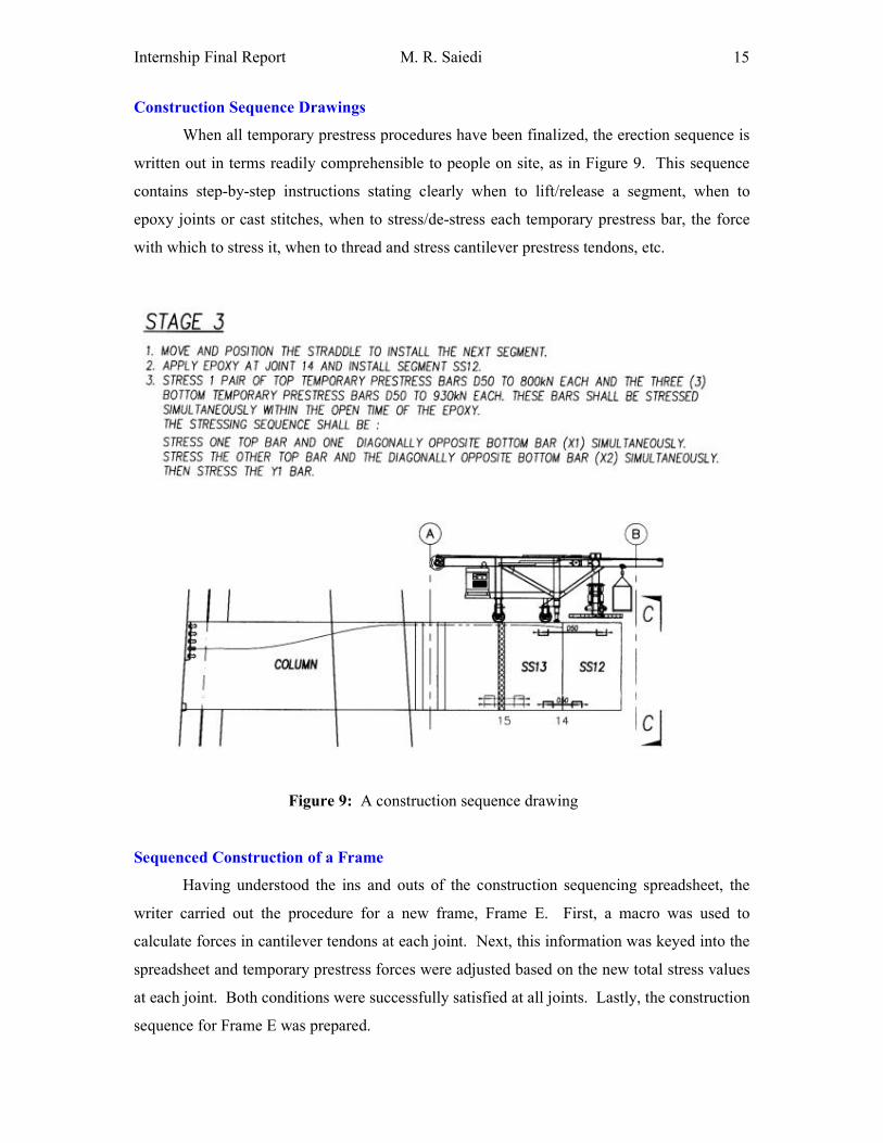
Construction Sequence Drawings
When all temporary prestress procedures have been finalized, the erection sequence is
written out in terms readily comprehensible to people on site, as in Figure 9. This sequence
contains step-by-step instructions stating clearly when to lift/release a segment, when to
epoxy joints or cast stitches, when to stress/de-stress each temporary prestress bar, the force
with which to stress it, when to thread and stress cantilever prestress tendons, etc.
Figure 9: A construction sequence drawing
Sequenced Construction of a Frame
Having understood the ins and outs of the construction sequencing spreadsheet, the
writer carried out the procedure for a new frame, Frame E. First, a macro was used to
calculate forces in cantilever tendons at each joint. Next, this information was keyed into the
spreadsheet and temporary prestress forces were adjusted based on the new total stress values
at each joint. Both conditions were successfully satisfied at all joints. Lastly, the construction
sequence for Frame E was prepared.
Internship Final Report M. R. Saiedi
16
REINFORCED CONCRETE DESIGN
Designed Footings for Stacking Precast Segments
(See Logbook: Week 3 for details.)
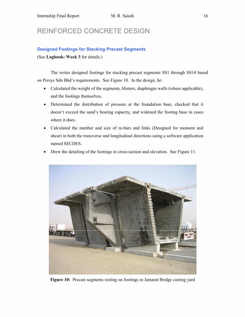
The writer designed footings for stacking precast segments SS1 through SS14 based
on Persys Sdn Bhd’s requirements. See Figure 10. In the design, he:
• Calculated the weight of the segments, blisters, diaphragm walls (where applicable),
and the footings themselves.
• Determined the distribution of pressure at the foundation base, checked that it
doesn’t exceed the sand’s bearing capacity, and widened the footing base in cases
where it does.
• Calculated the number and size of re-bars and links (Designed for moment and
shear) in both the transverse and longitudinal directions using a software application
named SECDES.
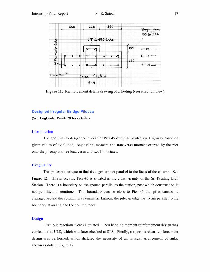
• Drew the detailing of the footings in cross-section and elevation. See Figure 11.
Figure 10: Precast segments resting on footings in Jamarat Bridge casting yard
Internship Final Report M. R. Saiedi
17
Figure 11: Reinforcement details drawing of a footing (cross-section view)
Designed Irregular Bridge Pilecap
(See Logbook: Week 28 for details.)
Introduction
The goal was to design the pilecap at Pier 45 of the KL-Putrajaya Highway based on
given values of axial load, longitudinal moment and transverse moment exerted by the pier
onto the pilecap at three load cases and two limit states.
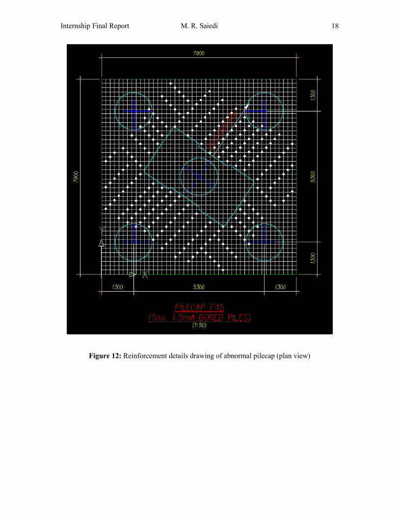
Irregularity
This pilecap is unique in that its edges are not parallel to the faces of the column. See
Figure 12. This is because Pier 45 is situated in the close vicinity of the Sri Petaling LRT
Station. There is a boundary on the ground parallel to the station, past which construction is
not permitted to continue. This boundary cuts so close to Pier 45 that piles cannot be
arranged around the column in a symmetric fashion; the pilecap edge has to run parallel to the
boundary at an angle to the column faces.
Design
First, pile reactions were calculated. Then bending moment reinforcement design was
carried out at ULS, which was later checked at SLS. Finally, a rigorous shear reinforcement
design was performed, which dictated the necessity of an unusual arrangement of links,
shown as dots in Figure 12.
Internship Final Report M. R. Saiedi
18
Figure 12: Reinforcement details drawing of abnormal pilecap (plan view)
Internship Final Report M. R. Saiedi
19
QUANTITY SURVEYING
Assessed a Bridge in Terms of Value Engineering
(See Logbook: Week 16 for details.)
Value Engineering
In Benaim’s structural design guidelines, there are acceptable ranges for the amounts
of concrete, reinforcement and prestress that can be put into certain structures. Normally the
Quantity Surveyor verifies the quantities achieved in the Engineer’s design. This way, we can
ensure that all structural design is at least, not too far off the economical value. This practice
is called ‘Value Engineering’ and is popular in the private sector.
Task
The writer’s supervisor appointed him to assess the suitability of a typical frame of the
Jamarat Bridge for value engineering. Frame B was chosen because it includes most features
of other frames without having the complications of Jamarat Area frames. The task was to
find the proportions of ‘Mass of reinforcement’ and ‘Mass of prestress’ to ‘Area of deck’ and
‘Volume of concrete’, as well as the ratio of ‘Volume of concrete’ to ‘Area of deck’, all only
in the precast portion of the frame.
Procedures
First, the quantities involved in the fractions were calculated separately and then they
were divided to find the ratios. The writer went to great lengths to ensure his calculations are
as comprehensive as possible. Table 3 summarizes the results and compares them with
Benaim standards for similar spans. Fractions involving steel and ‘Area of deck’ are better
indicators than those involving steel and ‘Volume of concrete’, since one can put in a great
deal of redundant concrete and still achieve an acceptable steel/concrete ratio despite
excessive steel. Besides, we are primarily concerned with the ‘Area of deck’ a design
provides and not the ‘Volume of concrete’ it uses.
Internship Final Report M. R. Saiedi
20
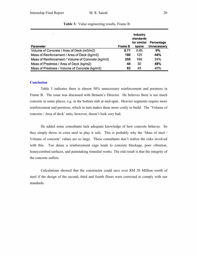
Table 3: Value engineering results, Frame B
Conclusion
Table 3 indicates there is almost 50% unnecessary reinforcement and prestress in
Frame B. The issue was discussed with Benaim’s Director. He believes there is too much
concrete in some places, e.g. in the bottom slab at mid-span. Heavier segments require more
reinforcement and prestress, which in turn makes them more costly to build. The ‘Volume of
concrete / Area of deck’ ratio, however, doesn’t look very bad.
He added some consultants lack adequate knowledge of how concrete behaves. So
they simply throw in extra steel to play it safe. This is probably why the ‘Mass of steel /
Volume of concrete’ values are so large. These consultants don’t realize the risks involved
with this. Too dense a reinforcement cage leads to concrete blockage, poor vibration,
honeycombed surfaces, and painstaking remedial works. The end result is that the integrity of
the concrete suffers.
Calculations showed that the constructor could save over RM 20 Million worth of
steel if the design of the second, third and fourth floors were corrected to comply with our
standards.
Internship Final Report M. R. Saiedi
21
Quantified Steel and Concrete in Tunnel U-Walls
(See Logbook: Week 17 for details.)
Introduction
The Midfield Access Road Tunnel in the New Doha International Airport passes under
one runway and two taxiways. It starts with a retaining wall, continues in the form of a U-
wall and develops into a full tunnel segment before converting into a U-wall again and then
another retaining wall at the end. The writer assisted Benaim’s Quantity Surveyor by
estimating the quantities of reinforcement and concrete in both U-wall segments of the tunnel.
Mass of Reinforcement
A spreadsheet was used that took the size, number and length of bars for each bar
mark and computed the combined mass of all bars in the segment.
Volume of Concrete
The complex cross-section had to be broken down into multiple simpler parts. Some
parts had the shape of an unconventional kind of solid the writer hadn’t encountered before,
the volume of which he determined.
Steel/Concrete Ratio
The ratio of steel to concrete was figured at 69 kg/m3. In bridges and buildings,
however, this ratio is around 200 kg/m3. The reason for this difference is that the bottom
slabs of these U-walls are made extremely thick (up to 2.2 m) in order to counteract uplifting
forces from the adjacent soil through self-weight. Therefore, these slabs are full of concrete
with comparatively little reinforcement only at the top and bottom. This lowers the
steel/concrete ratio significantly.
Internship Final Report M. R. Saiedi
22
SOFTWARE
The writer worked with a variety of civil engineering software, including:
• STAAD: Analysis and design for structural engineering
(See Logbook: Weeks 19 & 20 for details.)
• ENCAD: Structural analysis
(See Logbook: Week 7 for details.)
• In-house programs (produced by Benaim for Benaim):
o SECDES: Section reinforcement design
(Used in Logbook: Week 19 & 20, 28.)
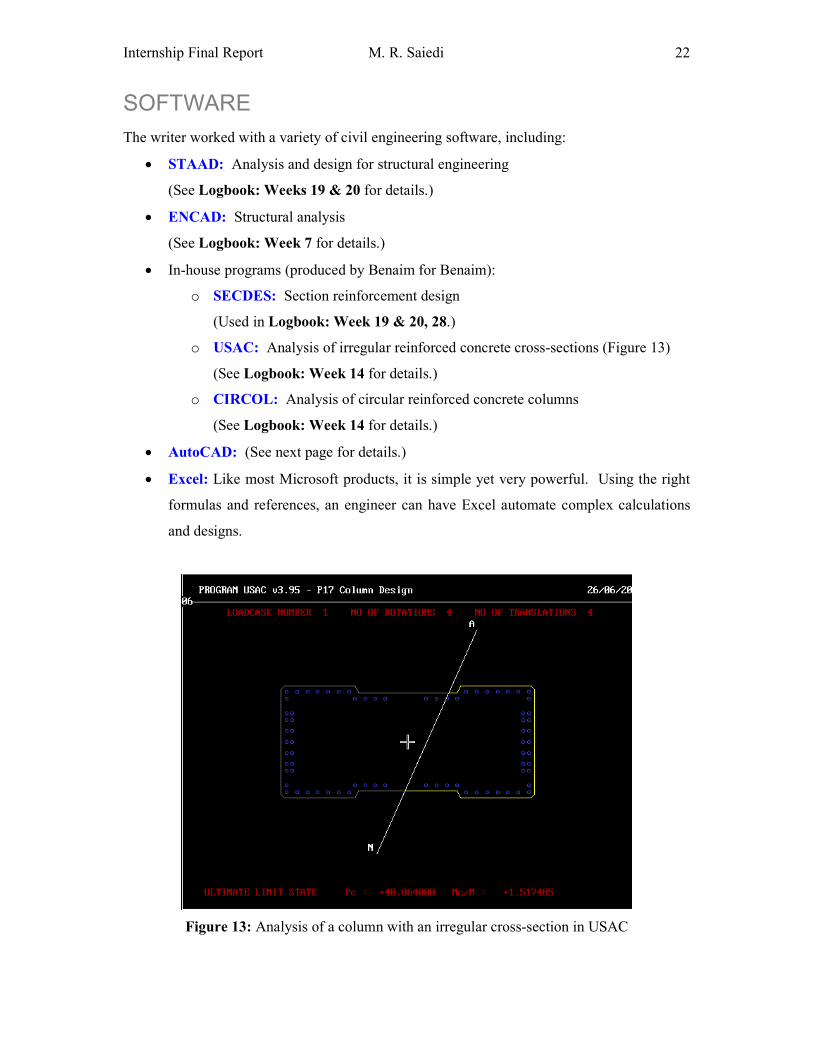
o USAC: Analysis of irregular reinforced concrete cross-sections (Figure 13)
(See Logbook: Week 14 for details.)
o CIRCOL: Analysis of circular reinforced concrete columns
(See Logbook: Week 14 for details.)
• AutoCAD: (See next page for details.)
• Excel: Like most Microsoft products, it is simple yet very powerful. Using the right
formulas and references, an engineer can have Excel automate complex calculations
and designs.
Figure 13: Analysis of a column with an irregular cross-section in USAC
Internship Final Report M. R. Saiedi
23
Worked with AutoCAD
Produced Bulkhead Detail Drawings
(See Logbook: Week 10 for details.)
Bulkhead detail drawings are used to build bulkhead steel moulds. The writer had to
prepare bulkhead detail drawings for frames F and M1. These frames were very similar to
frame B, for which these drawings had already been prepared. So the writer simply copied
and modified them. This meant removing and adding ducts based on existing tendon profiles
to suit the new frames.
The AutoCAD work involved a great deal of copying, mirroring, offsetting, showing
dimensions, clouding, and updating title blocks (including drawing notes, names and
revisions). The work was then verified by another draftsperson before being issued to the
client. Every civil engineer should be skilled at working with AutoCAD and this task was
very good practice.
Created Drawings to Supplement Calculations
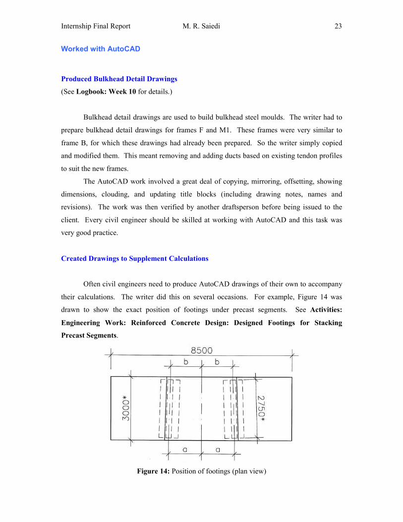
Often civil engineers need to produce AutoCAD drawings of their own to accompany
their calculations. The writer did this on several occasions. For example, Figure 14 was
drawn to show the exact position of footings under precast segments. See Activities:
Engineering Work: Reinforced Concrete Design: Designed Footings for Stacking
Precast Segments.
Figure 14: Position of footings (plan view)
Internship Final Report M. R. Saiedi
24
MISCELLANEOUS
Produced Bar Bending Schedules
(See Logbook: Week 22 for details.)
Bar Bending Schedules
A Bar Bending Schedule (BBS) is a list of reinforcement types, dimensions, quantities
and bar mark numbers cross-referring to the reinforcement detail drawing of a reinforced
concrete member. Benaim prepare these schedules as part of the process of converting design
drawings to shop drawings. Using a BBS, bending machine operatives can cut and bend all of
a member’s reinforcement bars without having to know their locations within the member.
Task
The writer’s task was to produce BBS’s for a U-wall zone of the Midfield Access
Road Tunnel in the New Doha International Airport. Full BBS’s were produced based on
reinforcement details drawings and concrete outlines. These BBS’s comply with BS 8666, a
standard containing specifications for scheduling, dimensioning, bending and cutting of steel
reinforcement for concrete.
Prepared Bridge-Related Masters Research Proposal
(See Logbook: Week 23 for details.)
The writer is currently looking for opportunities for postgraduate study by research. A
research proposal, i.e. a brief outline of the intended research, had to be prepared as part of the
application process.
The writer chose bridges as the research area because he has taken an interest in them
since he started working for Benaim (Malaysia). “Optimized Segmental Box Girders for a
Long-Span Concrete Bridge” was the chosen topic. Next, a draft of the research proposal was
prepared with the help of a university lecturer. The writer’s supervisor at Benaim then helped
him correct the document by clarifying ideas, explaining the design process and making the
information better conform to reality.
Internship Final Report M. R. Saiedi
25
Read Civil Engineering Publications
(See Logbook: Week 22 for details.)
Introduction
Benaim (Malaysia) has subscriptions to some of the world’s best civil engineering
publications including New Civil Engineer (NCE), The Structural Engineer, Steel
Construction News and Concrete for the Construction Industry. On average, the writer read
one magazine a week. This helped him learn about the world’s major construction projects,
understand project management and develop stronger engineering common sense.
New Civil Engineer
The New Civil Engineer is the writer’s favourite. The articles present basic
information about a project before discussing the challenges and innovations that make it
unique. Vivid photos taken from different angles accompany descriptions of the structure’s
main components. Diagrams illustrate the construction sequence. Numeric quantities provide
an accurate impression of the dimensions and scale of the project.
New Civil Engineer’s recent issues look at levee reconstruction in New Orleans, USA
after Hurricane Katrina, the UK’s Wembley Stadium roof and a flood protection barrier in
Venice, Italy.
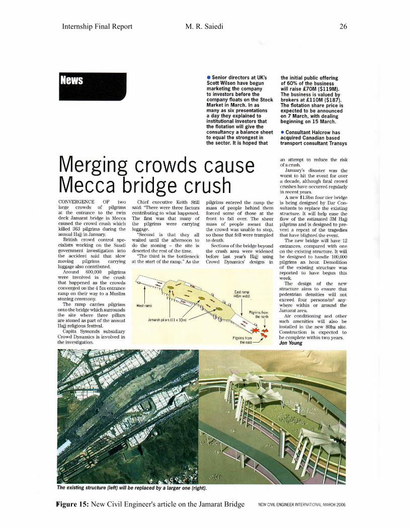
Article on Jamarat Bridge
Interestingly, the March 2006 issue has an article about our current project, the
Jamarat Bridge in Mina. See Figure 15. The news story reports on the tragic deaths that
occurred earlier this year. The last four paragraphs give a concise technical description of the
bridge, designed to prevent similar incidents in the future.
Internship Final Report M. R. Saiedi
26
Figure 15: New Civil Engineer's article on the Jamarat Bridge
Internship Final Report M. R. Saiedi
27
SITE VISITS
Visited Balakong Interchange, KL: Ramps
(See Logbook: Week 5 for details.)
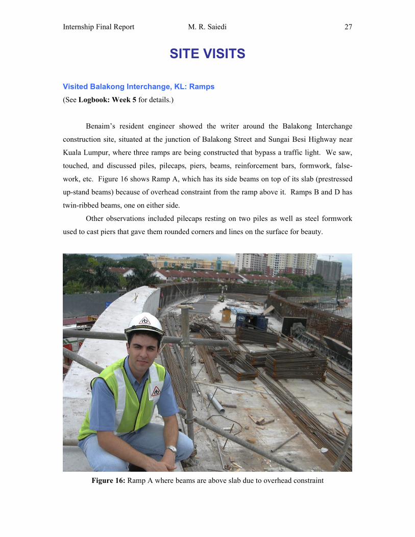
Benaim’s resident engineer showed the writer around the Balakong Interchange
construction site, situated at the junction of Balakong Street and Sungai Besi Highway near
Kuala Lumpur, where three ramps are being constructed that bypass a traffic light. We saw,
touched, and discussed piles, pilecaps, piers, beams, reinforcement bars, formwork, false-
work, etc. Figure 16 shows Ramp A, which has its side beams on top of its slab (prestressed
up-stand beams) because of overhead constraint from the ramp above it. Ramps B and D has
twin-ribbed beams, one on either side.
Other observations included pilecaps resting on two piles as well as steel formwork
used to cast piers that gave them rounded corners and lines on the surface for beauty.
Figure 16: Ramp A where beams are above slab due to overhead constraint
Internship Final Report M. R. Saiedi
28
Visited Balakong Interchange, KL: Prestressing
(See Logbook: Week 18 or details.)
Introduction
The writer went to Balakong Interchange for a second time together with colleagues
from the Benaim office. We were there to see prestressing being carried out on the unfinished
Ramp B. The span being stressed was a box girder with a constant depth of 4 metres.
Tendons, Anchor Blocks and Wedges
Tendons and anchor blocks were in place in the webs and were ready for stressing.
Strand ends are marked with spray paint. This helps with the measurement of elongation after
stressing. The tendons constitute 31 strands each, passing through the 31 holes in an anchor
block. Wedges are placed around strands and seated into the anchor block so that on the
release of the jack the wedges grip the strand and transfer the force onto the anchor.
Jack
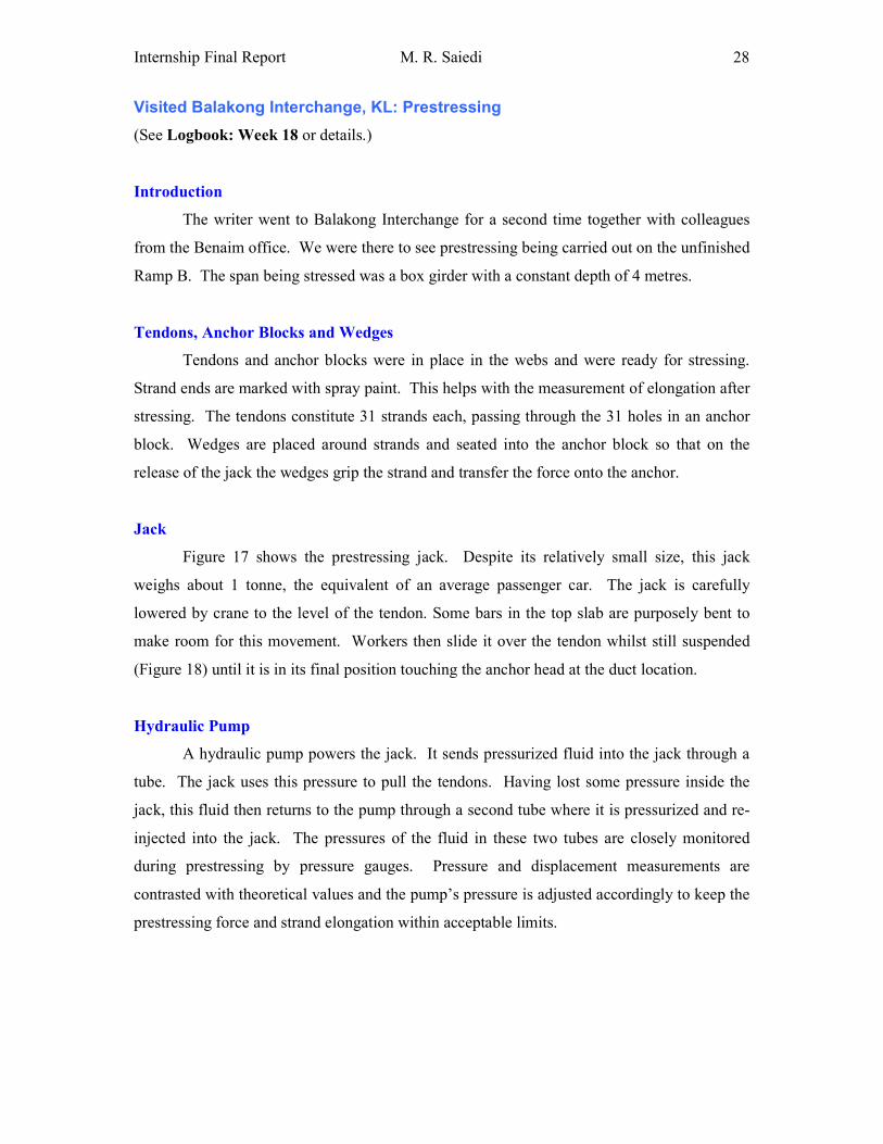
Figure 17 shows the prestressing jack. Despite its relatively small size, this jack
weighs about 1 tonne, the equivalent of an average passenger car. The jack is carefully
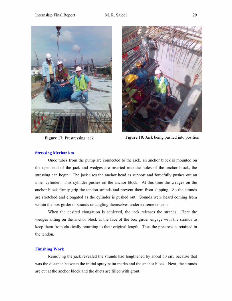
lowered by crane to the level of the tendon. Some bars in the top slab are purposely bent to
make room for this movement. Workers then slide it over the tendon whilst still suspended
(Figure 18) until it is in its final position touching the anchor head at the duct location.
Hydraulic Pump
A hydraulic pump powers the jack. It sends pressurized fluid into the jack through a
tube. The jack uses this pressure to pull the tendons. Having lost some pressure inside the
jack, this fluid then returns to the pump through a second tube where it is pressurized and re-
injected into the jack. The pressures of the fluid in these two tubes are closely monitored
during prestressing by pressure gauges. Pressure and displacement measurements are
contrasted with theoretical values and the pump’s pressure is adjusted accordingly to keep the
prestressing force and strand elongation within acceptable limits.
Internship Final Report M. R. Saiedi
29
Figure 17: Prestressing jack
Figure 18: Jack being pushed into position
Stressing Mechanism
Once tubes from the pump are connected to the jack, an anchor block is mounted on
the open end of the jack and wedges are inserted into the holes of the anchor block, the
stressing can begin: The jack uses the anchor head as support and forcefully pushes out an
inner cylinder. This cylinder pushes on the anchor block. At this time the wedges on the
anchor block firmly grip the tendon strands and prevent them from slipping. So the strands
are stretched and elongated as the cylinder is pushed out. Sounds were heard coming from
within the box girder of strands untangling themselves under extreme tension.
When the desired elongation is achieved, the jack releases the strands. Here the
wedges sitting on the anchor block at the face of the box girder engage with the strands to
keep them from elastically returning to their original length. Thus the prestress is retained in
the tendon.
Finishing Work
Removing the jack revealed the strands had lengthened by about 50 cm, because that
was the distance between the initial spray paint marks and the anchor block. Next, the strands
are cut at the anchor block and the ducts are filled with grout.
Internship Final Report M. R. Saiedi
30
Visited New Pantai Highway, KL
(See Logbook: Week 6 or details.)
Introduction
The New Pantai Highway commences from Subang Jaya and terminates at the Kuchai
Lama Interchange of the KL-Seremban Expressway. The 20 km highway features 7
interchanges, 4 toll plazas and 19 bridges including 2 underpasses. See Appendix A for
more details. Benaim’s Asisstant Resident Engineer was the writer’s guide around the site.
Segmental Box Girder
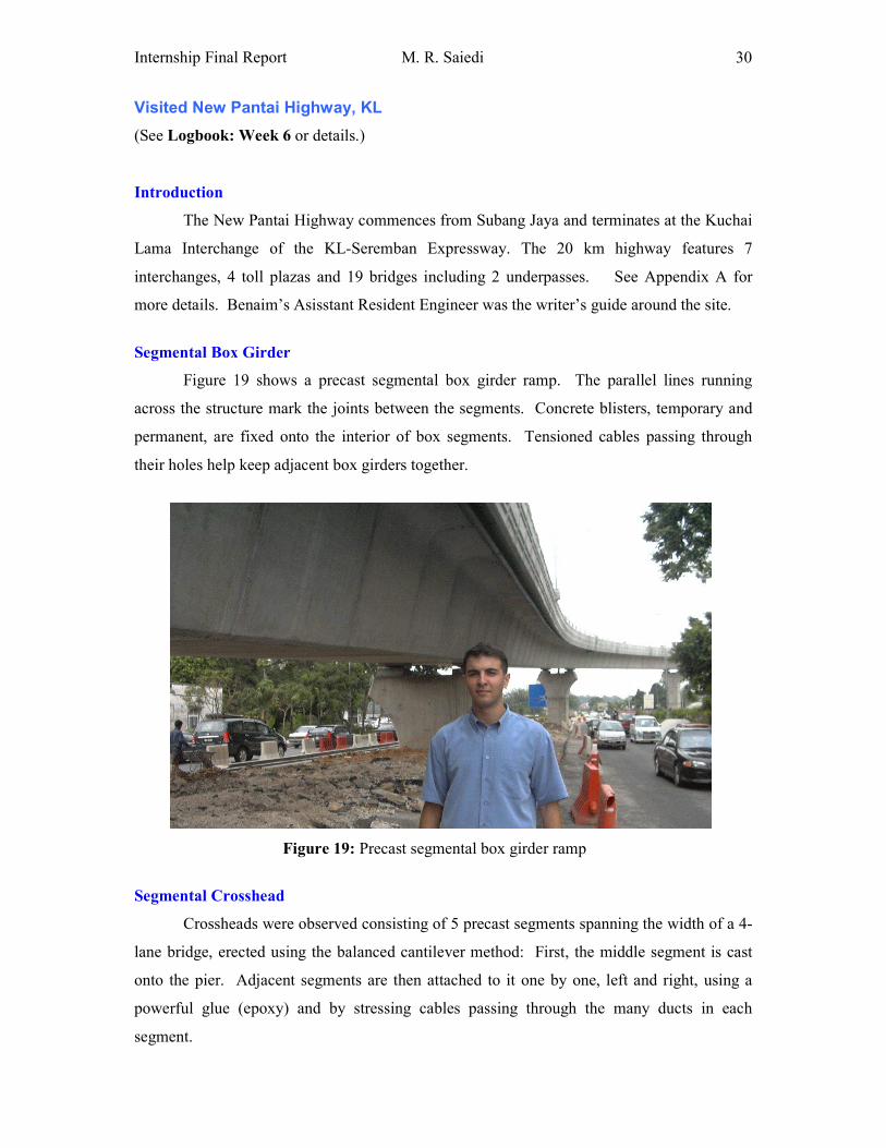
Figure 19 shows a precast segmental box girder ramp. The parallel lines running
across the structure mark the joints between the segments. Concrete blisters, temporary and
permanent, are fixed onto the interior of box segments. Tensioned cables passing through
their holes help keep adjacent box girders together.
Figure 19: Precast segmental box girder ramp
Segmental Crosshead
Crossheads were observed consisting of 5 precast segments spanning the width of a 4-
lane bridge, erected using the balanced cantilever method: First, the middle segment is cast
onto the pier. Adjacent segments are then attached to it one by one, left and right, using a
powerful glue (epoxy) and by stressing cables passing through the many ducts in each
segment.
Internship Final Report M. R. Saiedi
31
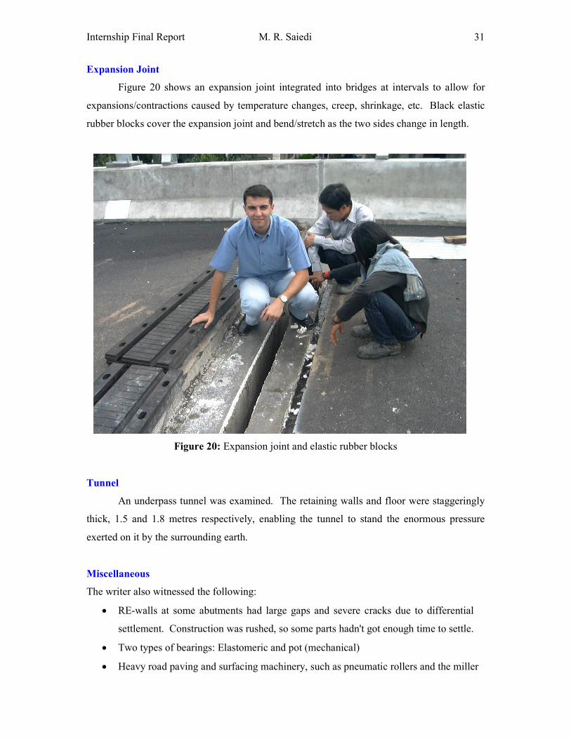
Expansion Joint
Figure 20 shows an expansion joint integrated into bridges at intervals to allow for
expansions/contractions caused by temperature changes, creep, shrinkage, etc. Black elastic
rubber blocks cover the expansion joint and bend/stretch as the two sides change in length.
Figure 20: Expansion joint and elastic rubber blocks
Tunnel
An underpass tunnel was examined. The retaining walls and floor were staggeringly
thick, 1.5 and 1.8 metres respectively, enabling the tunnel to stand the enormous pressure
exerted on it by the surrounding earth.
Miscellaneous
The writer also witnessed the following:
• RE-walls at some abutments had large gaps and severe cracks due to differential
settlement. Construction was rushed, so some parts hadn't got enough time to settle.
• Two types of bearings: Elastomeric and pot (mechanical)
• Heavy road paving and surfacing machinery, such as pneumatic rollers and the miller
Internship Final Report M. R. Saiedi
32
ADMINISTRATIVE WORK
DID ADMINISTRATIVE DRAFTING WORK
Drawings Received
The writer printed received AutoCAD drawings. We receive a number of drawings
from FSA (Freyssinet Saudi Arabia, one of the erection contractors) and DAH (Dar Al-
Handasah, the consulting engineer) almost daily. These drawings need to be registered,
printed and filed on a regular basis for immediate accessibility and to prevent accumulation
and disorder.
Check-Prints
The writer filed a large number of check-prints. A check-print is a printout of a
drawing created by a draftsperson, which is checked by another person to locate possible
errors. He or she highlights correct information in green, marks mistakes in red and signs the
stamp. The draftsperson then corrects these errors and the revision goes up (e.g. Rev. A1
becomes Rev. A2) before the drawing is re-checked. When there are no errors remaining, the
drawing is issued to the client (for instance at Rev. A). These standard procedures ensure that
every drawing’s evolution is clearly recorded.
Drawings Issued
The writer photocopied and filed new issued drawings. We make 3 hard copies of
every new drawing that we issue. One copy is sent to the client by courier, one is kept under
“Issued Drawings” on which amendments may be jotted down, and the third is kept under
“Original Drawings” and is left untouched.
Internship Final Report M. R. Saiedi
33
UPDATED INCOMING DRAWINGS REGISTER
Introduction
Benaim (Malaysia) keeps track of all incoming and outgoing letters, faxes, telephone
conversations and drawings in order to meet ISO standards, maintain organization and avoid
confusion. In the incoming drawings register, they record the drawing number, title, revision,
status, whom they’ve received it from and the date of its receipt.
Progression of Drawings
Each drawing prepared by the consultant is revised several times until fully approved
by the client. The client’s assessment of a drawing can be Approved, Approved as noted,
Resubmit for approval, or Rejected. Also, depending on its life-cycle stage, a drawing’s
status could be Action, Approval, As Built, Comment, Construction, Information,
Preliminary, Review, Tender or Verification.
Task
First, the writer updated the incoming drawings register (a computer file). Then the
date was stamped on all received drawings and they were placed in the Incoming Drawings
file in order. If a drawing already existed in the file, the old drawing would be replaced with
the newer one. Then the old drawing would be stamped with the word “Superseded” and be
placed in the Superseded Drawings file.

Internship Final Report M. R. Saiedi
34
CHECKED TENDON PROFILES
(See Logbook: Week 10 or details.)
Tendon Profiles
Tendon profiles or prestressing layouts are drawings that indicate the positions of
prestressing tendons in elevation and in plan. Benaim uses an Auto-CAD application (.lsp
file) to automatically extract from the drawings the tendons’ coordinates at certain intervals,
and put them in a large table beneath the drawing.
Tendons in Jamarat Bridge
In the Jamarat Bridge, tendons in top and bottom slabs are straight through most of
their length (i.e. have constant Y and Z coordinates), but twist and turn near ends where they
are anchored. Letters are used to represent repeated tendon coordinates. These same letters
are used to signify tendon locations on bulkhead detail drawings.
Task
The writer compared Benaim’s tendon profile drawings to FSA’s (Freyssinet Saudi
Arabia) drawings, which we use as our primary source. Correct coordinates were highlighted
in green and incorrect figures were marked with red. The ‘Layout Check’ field on the stamp
was then initialled. See Figure 21.
Figure 21: A tendon profile checked, corrected and initialled by the writer
Internship Final Report M. R. Saiedi
35
CHECKED DRAWINGS AS PART OF INTERNAL AUDIT
(See Logbook: Week 24 or details.)
Internal Audit
Benaim (Malaysia) have completed producing shop-drawings for the first floor of the
Jamarat Bridge. The second, third and fourth floors are very similar to the first floor. So
much so that to produce their drawings, we will basically copy first floor drawings, making
only minor amendments where necessary. So before we start producing drawings for the
other floors, we need to make sure our current drawings are thoroughly correct. Otherwise,
corrections will later have to be made to all four floors instead of only one, costing us a great
deal of time and energy. We are therefore carrying out a comprehensive internal audit of all
of our latest drawings.
Task
The writer’s job was to compare the framing plan provided by DAH (the designer)
with our framing plan spreadsheet as well as our casting layouts (L-series), segment outlines
(S-series) and reinforcement details (R-series) drawings. Over 300 drawings were checked
for mistakes and a brief report of findings and corrections was produced.
PREPARED DRAWINGS FOR EXTERNAL AUDIT
External Audit
An external auditor was going to visit our office to renew our ISO 9001 certification.
The writer had to ensure that all our Jamarat Bridge drawings and bar bending schedules (i.e.
superseded copies, issued copies, original copies and check-prints) comply with Benaim’s
Quality Management System (QMS). This document requires that certain procedures be
followed in issuing, checking, revising and filing of drawings and bar schedules. Due to
copyright issues, these procedures couldn’t be reproduced in this report.
Findings
Although our engineers and technicians had generally abided by the rules well, slight
mistakes were spotted in some cases. Examples included misplaced drawings as well as
missing comments, signatures and “Not Yet Issued” stamps.
Internship Final Report M. R. Saiedi
36
LESSONS & EXPERIENCES
Technical Lessons
1. Bridges
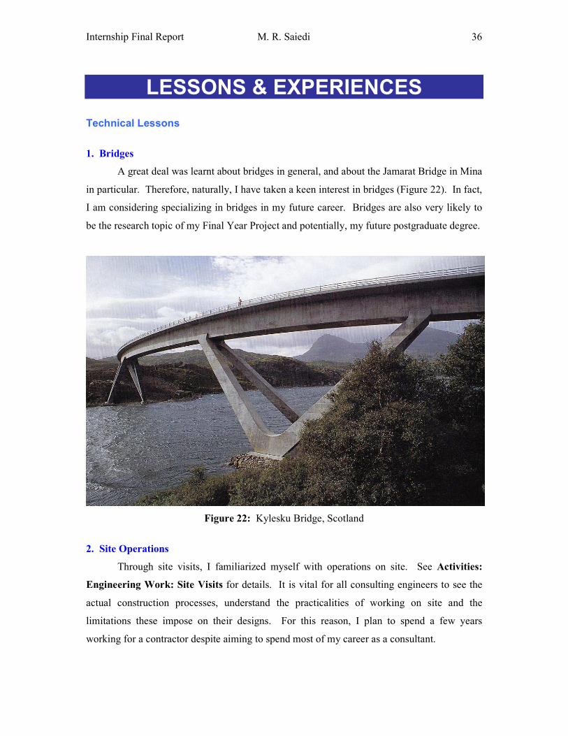
A great deal was learnt about bridges in general, and about the Jamarat Bridge in Mina
in particular. Therefore, naturally, I have taken a keen interest in bridges (Figure 22). In fact,
I am considering specializing in bridges in my future career. Bridges are also very likely to
be the research topic of my Final Year Project and potentially, my future postgraduate degree.
Figure 22: Kylesku Bridge, Scotland
2. Site Operations
Through site visits, I familiarized myself with operations on site. See Activities:
Engineering Work: Site Visits for details. It is vital for all consulting engineers to see the
actual construction processes, understand the practicalities of working on site and the
limitations these impose on their designs. For this reason, I plan to spend a few years
working for a contractor despite aiming to spend most of my career as a consultant.
Internship Final Report M. R. Saiedi
37
3. Reading Drawings
I learnt to read drawings, that is to:
• Visualize structures in 3D based on views in plan, cross-section and elevation
• Imagine scales and dimensions
• Look for specific information
• Follow cross-references between drawings
• Understand arrangements of bars in reinforcement details drawings
4. Software
I am now comfortable with routine applications of structural analysis and design
software. See Activities: Engineering Work: Software for details.
5. Design Codes
In UTP, civil engineering students are exposed to BS 8110: "Structural use of
concrete", BS 5950: "Structural use of steelwork in building" and parts of AASHTO codes.
At Benaim, I got the chance to use other codes too, such as BS 5400: "Steel, concrete and
composite bridges" and BS 8666: "Specifications for steel reinforcement for concrete".
6. Cost of Materials
Through asking my colleagues, I got a feel for the price of concrete, reinforcement
steel and prestressing steel. This information was then used to estimate potential savings on
steel in the Jamarat Bridge had it been "value-engineered". See Activities: Engineering
Work: Quantity Surveying: Assessed a Bridge in Terms of Value Engineering for details.

Internship Final Report M. R. Saiedi
38
Non-Technical Lessons
1. Project Management
I did not do any project management myself, but I learnt about it through observation.
My supervisor, Mr. Akram Malik (Director), regularly moved around the office, checking on
people and making sure projects are going according to plan.
I sat in on biweekly staff meetings held by Mr. Afshin Forouzani (Director) where we
were briefed on the status of projects (our current projects and bids for future jobs), accounts
(cash-flow, invoicing, etc.) and human resources issues. Through these meetings I became
familiar with the challenges of working in the private sector.
Benaim (Malaysia) Directors personally advised me to avoid being pigeonholed by
employers who may not be interested in my development, to keep my head up and to learn
about non-technical aspects of engineering too. They added that a combination of sound
technical skills and project management would build a bright career.
2. Progression of Drawings
Through filing, checking and registering drawings, I learnt about their evolution. I
saw sketches become check-prints, check-prints become issued drawings and issued drawings
get revised as they were passed back and forth between our clients and us.
3. Administrative Work
I learned that engineering in the private sector means that jobs have to be fully
managed. Thus, they require substantial administrative input in addition to technical input
and engineers need to be able to do this. Although not glamorous, administrative work is an
inevitable part of the job and there is no escaping it.
Internship Final Report M. R. Saiedi
39
4. Office Culture
The change from student life to working life was drastic. I suddenly found myself in a
professional environment where I learnt to:
• Focus on work during office hours, keeping personal matters to a minimum
• Keep superiors informed and satisfied regarding assigned jobs
• Avoid disturbing others: Choose the right time to interrupt them; speak quietly
• Be responsible: Return things to their original state after use; keep the office tidy
• Be punctual: Come and go on time
5. Social Skills
Kuala Lumpur was a new city for me, away from my university and home. In order to
survive emotionally, I made new friends both outside and inside the workplace and
maintained these friendships as frequently as possible. I even attended a bowling session
arranged by the company.
At work, my communicational skills improved significantly. I learnt to deal with
people of all levels: site workers, other trainees, draftspersons, engineers and directors. Good
relations were maintained with all employees to avoid potential conflicts. Tactfulness,
modesty and respect were practised at all times.
Dealing with superiors was a tricky business. The famous quote, "A man should live
with his superiors as he does with his fire: not too near, lest he burn; not too far, lest he
freeze." (Albert Pike) very much applies in the workplace.
6. Writing Skills
My writing skills improved considerably through writing weekly reports and this Final
Report. The book "Technical Communication: A practical approach" by W. S. Pfeiffer was
consulted repeatedly in writing these documents. I also attended Business English training
provided by the company.
Internship Final Report M. R. Saiedi
40
Miscellaneous Skills
Individual Skills
The nature of most tasks assigned to me was individual. This meant I had to be self-
sufficient and resourceful. Finding specific information among hundreds of drawings and
pages of design codes was difficult at first, but I became skilled at this over time. Where
information had to be sought from colleagues, I had to persistently but considerately pursue
them for answers.
Teamwork
Teamwork was present in the following activities:
• Draftspersons passed their check-prints to me. I checked these and asked them to
correct mistakes, if any. We sometimes had to work together to issue drawings before
a deadline.
• I often assisted the Jamarat Bridge Project Technician in administrative drafting work
when he had more work than he could handle alone or to help him catch up with
backlog.
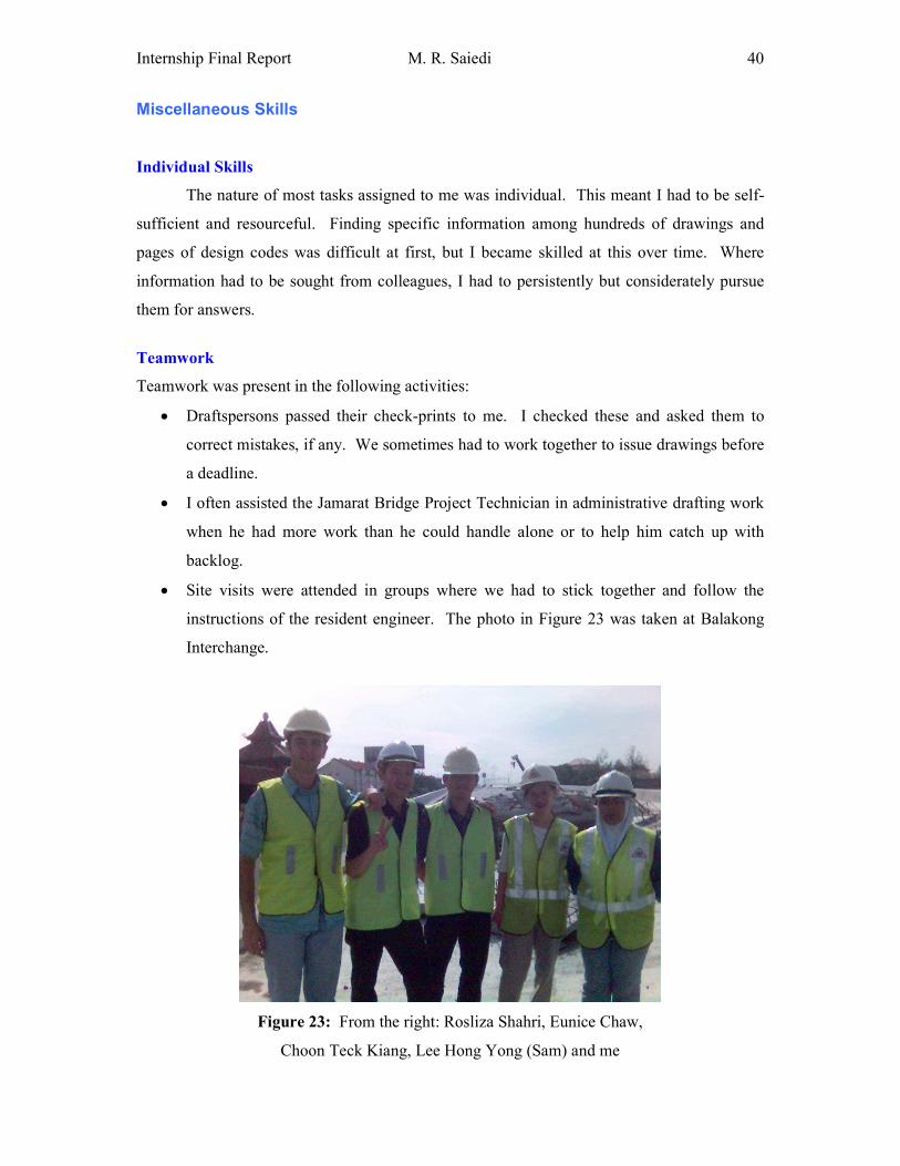
• Site visits were attended in groups where we had to stick together and follow the
instructions of the resident engineer. The photo in Figure 23 was taken at Balakong
Interchange.
Figure 23: From the right: Rosliza Shahri, Eunice Chaw,
Choon Teck Kiang, Lee Hong Yong (Sam) and me
Internship Final Report M. R. Saiedi
41
Leadership Skills
The tasks assigned to me did not involve leadership. This was because, being a
trainee, I was at the bottom of the organizational ladder, had no subordinates and therefore,
had nobody to lead.
Nevertheless, I did learn by observing project managers lead their respective teams.
They all have the following traits in common:
• They set a good example through their own discipline, enthusiasm and hard work.
• They approach team members in a considerate, friendly and humble manner.
• They encourage them in return for good performance.
• They are strict and demanding when necessary.
Management Skills
I was in control of my own affairs. I managed my time and tasks by prioritising based
on level of urgency and importance. See Lessons & Experiences: Technical Lessons:
Project Management for more details.
Safety Training & Awareness
In a design office, unlike a construction site, there is very little that can endanger the
safety of employees. Despite this, Benaim (Malaysia) takes every precaution to ensure
nobody gets hurt. We participated in a fire drill conducted in all Uptown buildings. We had a
workstation audit about the suitability of our computer screens, seats and lighting. Finally,
during our site visits, we wore safety helmets.
Internship Final Report M. R. Saiedi
42
Problems and Challenges
The Language Barrier
Malaysian employees frequently spoke Bahasa Malaysia or Chinese among
themselves. I could not understand either of these languages, so sometimes I felt left out of
their circles.
Not Now!
Taught to be curious and critical-thinking, I had many questions to ask my colleagues.
At times, however, they were simply too busy to answer them, so I had to wait. This delayed
work.
Not Again!
Sometimes, I was given a great deal of administrative work, although I preferred
engineering work. But there are always certain parts of one's job that one won't enjoy; being
an employee means doing them anyway.
Exhausted
Working hours at Benaim (Malaysia) are from 8:30 AM to 6:00 PM with a one-hour
break for lunch. The long working hours were occasionally hard on me. And there was little
time left for life outside of the workplace. The fact that adults spend most of their waking
hours toiling at work was a shocking revelation for me. But then I realized if I were
passionate about my future job, I would be perfectly happy with this.
Internship Final Report M. R. Saiedi
43
CONCLUSION & RECOMMENDATIONS
CONCLUSION
The internship has met all the objectives and its success has surpassed my
expectations. It has opened my eyes to working life, enlightened me socially, and matured me
as an adult. It has strengthened my technical base and enabled me to integrate theory with
engineering practice. Finally, it has given me a clear sense of direction in my future studies
and career as a civil engineer.
RECOMMENDATIONS
Host Company
My training experience at Benaim (Malaysia) has been so satisfying that there is very
little to complain about. I feel very lucky to have been offered a place here.
I am perfectly happy with the style of supervision of Mr. Akram Malik (Director).
Other members of staff, too, have been very friendly and supportive. The fact that the
company is British-owned with expatriate staff at senior levels makes it an ideal host for
international students as English is used very widely. Facilities are in great condition and the
work environment is very organized, professional and conducive to learning.
Industrial Internship Unit
I am also pleased with the internship unit. They have actively responded to all
questions and requests. The only setback may have been the unavailability of information on
the industrial internship e-learning course.
UTP
I would like to recommend that the Civil Engineering Department add bridges to their
undergraduate curriculum in some way. At Benaim (Malaysia), I have learnt that the bridge is
one of the most imaginative, challenging and remarkable civil engineering structures.

Internship Final Report M. R. Saiedi
44
APPENDICES
Appendix A: Benaim Company Profile: Bridges