Embed Size (px)
Citation preview
INTELLIPRO® Variable Speed Pump Installation and User’s Guide
IMPORTANT SAFETY INSTRUCTIONSREAD AND FOLLOW ALL INSTRUCTIONS
SAVE THESE INSTRUCTIONS
INTELLIPRO® VARIABLE SPEED
INSTALLATION ANDUSER’S GUIDE
ULTRA ENERGY EFFICIENT PUMP
INTELLIPRO® Variable Speed Pump Installation and User’s Guide
i
P/N 354831 Rev. B 12/2/13
TABLE OF CONTENTS
External Control .................................................
Features ..............................................................Quick Clean/Only High Speed Override FeatureTime Out
Priming .................................................................Setting Priming FeaturesDisabling Priming with an Automation System
Anti Freeze .........................................................
Connecting to an Automation System ..............External Control with IntelliComm
Communication CenterConnecting to EasyTouch and
IntelliTouch SystemsConnecting to SunTouch Systems
User Maintenance ...............................................Pump Strainer BasketCleaning the Pump Strainer BasketWinterizing
Servicing ..............................................................Motor CareShaft Seal ReplacementPump DisassemblyPump ReassemblyDrive Assembly Removal and InstallationAlerts and Warnings
Troubleshooting ..................................................
Replacement Parts .............................................Illustrated Parts ListPump DimensionsPump Performance CurvesElectrical SpecificationsOperator Control Panel Quick Reference Guide
Important Pump Warning and Safety Instructions ..............................................
Pump Overview ....................................................Pump Overview and FeaturesDrive Assembly and Control PanelExternal ControlMotor Features
Installation ...........................................................LocationPipingValves and FittingsElectrical Wiring Installation
Operating the Pump .............................................Priming the Pump Using the Operator Control PanelStarting and Stopping the Pump Operating the Pump at Preset SpeedsPump Operating ModesControl Panel LanguageControl Panel: Pump Menu Guide
Pump Settings ......................................................Pump AddressSet Time & Set AM/PM or 24 ClockSet Temperature UnitScreen Contrast LevelLanguageSet Maximum Speed (RPM)Set Minimum Speed (RPM)Password Protection
Setting Speeds 1-8 ..............................................Pump Operating Modes Setting Speeds in Manual or Egg Timer Mode
(Speeds 1-4 only)Setting Speeds 1-8 in Schedule Mode
ii
11111
22223
44566667
888889999
1111
1112
12
131313
131415
16
17
17
1719
20202020
21212121222223
24
262627272728
If you have questions about ordering Pentair Water Pool and Spa replacement parts, and pool products, please contact:
CUSTOMER SERVICE / TECHNICAL SUPPORT
Customer Service and Technical Support, USA (8 A.M. to 4:30 P.M. — Eastern/Pacific Times)
Phone: (800) 831-7133
Fax: (800) 284-4151
Web siteVisit www.pentairpool.com or www.staritepool.com to find out information about Pentair products.
Sanford, North Carolina (8 A.M. to 4:30 P.M. ET)
Phone: (919) 566-8000
Fax: (919) 566-8920
Moorpark, California (8 A.M. to 4:30 P.M. PT)
Phone: (805) 553-5000 (Ext. 5591)
Fax: (805) 553-5515
Compatible with IntelliComm® Communication Center and EasyTouch®, IntelliTouch® and SunTouch® Control Systems.
* Translated versions of this manual are available online at / La versión en español de este manual del producto, se puede encontrar en línea a / Versiones en francés de este manual está disponible en línea en / Nederlandse versies van deze handleiding zijn online beschik-baar op / Deutsch-Versionen dieses Handbuchs sind online verfügbar unter / Versione italiana di questo manuale sono disponibili online all’indirizzo / Versões em português deste manual está disponível online em: http://www.pentairpool.com/es/pool-owner/manuals/.
INTELLIPRO® Variable Speed Pump Installation and User’s Guide
When installing and using this electrical equipment, basic safety precautions should always be followed, include the following:
Do not permit children to use this product.
RISK OF ELECTRICAL SHOCK. Connect only to a branch circuit protected by a ground-fault circuit-
interrupter (GFCI). Contact a qualified electrician if you cannot verify that the circuit is protected by a GFCI.
This unit must be connected only to a supply circuit that is protected by a ground-fault circuit-interrupter
(GFCI). Such a GFCI should be provided by the installer and should be tested on a routine basis. To test the GFCI, push the test button. The GFCI should interrupt power. Push the reset button. Power should be restored. If the GFCI fails to operate in this manner, the GFCI is defec-tive. If the GFCI interrupts power to the pump without the test button being pushed, a ground current is flowing, indicating the possibility of an electric shock. Do not use this pump. Disconnect the pump and have the problem corrected by a qualified service representative before using.
This pump is for use with permanent swimming pools and may also be used with hot tubs and spas
if so marked. Do not use with storable pools. A permanently-installed pool is constructed in or on the ground or in a building such that it cannot be readily disassembled for storage. A storable pool is constructed so that it is capable of being readily disassembled for storage and reassembled to its original integrity.
General Warnings• Never open the inside of the drive motor enclosure. There is a
capacitor bank that holds a 230 VAC charge even when there is no power to the unit.
• Thepumpisnotsubmersible.• Thepumpiscapableofhighflowrates;usecautionwheninstalling
and programming to limit pumps performance potential with old or questionable equipment.
• Coderequirementsfortheelectricalconnectiondifferfromstatetostate. Install equipment inaccordancewith theNationalElectricalCode and all applicable local codes and ordinances.
• Before servicing the pump; switch OFF power to the pump bydisconnecting the main circuit to the pump.
• Thisapplianceisnotintendedforusebypersons(includingchildren)ofreduced physical, sensory or mental capabilities, or lack of experience and knowledge, unless they have been given supervision or instruction concerning the use of the appliance by a person responsible for their safety.
FAILURETOFOLLOWALLINSTRUCTIONSANDWARNINGSCANRESULT INSERIOUSBODILY
INJURYORDEATH.THIS PUMP SHOULD BE INSTALLED AND SERVICED ONLY BY A QUALIFIED POOL SERVICE PROFESSIONAL. INSTALLERS, POOL OPERATORS AND OWNERS MUST READ THESE WARNINGS AND ALL INSTRUCTIONS IN THE OWNER’S MANUAL BEFORE USING THIS PUMP. THESE WARNINGS AND THE OWNER’S MANUAL MUST BE LEFT WITH THE POOL OWNER.
SUCTION ENTRAPMENT HAZARD: STAY OFFTHEMAINDRAINANDAWAYFROMALLSUCTIONOUTLETS!
THEUSEOFUNAPPROVEDCOVERSORALLOWINGUSEOFTHEPOOLORSPAWHENCOVERSAREMISSING,CRACKEDORBROKENCANRESULT INBODYORLIMBENTRAPMENT,HAIRENTANGLE-MENT,BODYENTRAPMENT,EVISCERATIONAND/ORDEATH.The suction at a drain or outlet can cause:Limb Entrapment: When a limb is sucked or inserted into an opening resulting in a mechanical bind or swelling. This hazard is present when a drain cover is missing, broken, loose, cracked or not properly secured.Hair Entanglement: When the hair tangles or knots in the drain cover, trapping the swimmer underwater. This hazard is present when the flow rating of the cover is too small for the pump or pumps.Body Entrapment: When a portion of the body is held against the drain cover trapping the swimmer underwater. This hazard is present when the drain cover is missing, broken or the cover flow rating is not high enough for the pump or pumps.Evisceration/Disembowelment: When a person sits on an open pool (particularly a child wading pool) or spa outlet and suction is applied directly to the intestines, causing severe intestinal damage. This hazard is present when the drain cover is missing, loose, cracked, or not properly secured.
F
THISPUMPPRODUCESHIGHLEVELSOFSUCTIONANDCREATESASTRONGVACUUMATTHEMAINDRAINATTHEBOTTOMOFTHEBODYOFWATER.THISSUCTIONISSOSTRONGTHATITCANTRAPADULTSORCHILDRENUNDERWATERIFTHEYCOMEINCLOSEPROXIMITYTOADRAINORALOOSEORBROKENDRAINCOVERORGRATE.
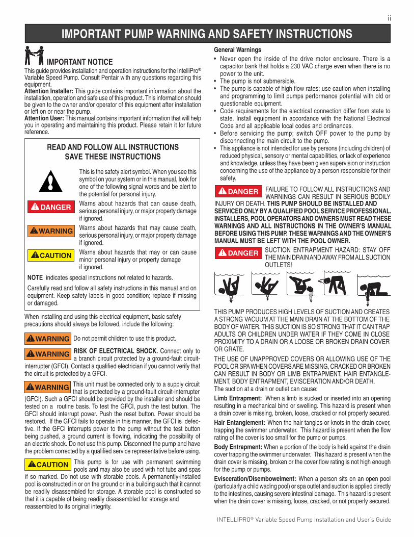
This guide provides installation and operation instructions for the IntelliPro® Variable Speed Pump. Consult Pentair with any questions regarding this equipment. Attention Installer: This guide contains important information about the installation, operation and safe use of this product. This information should begiventotheownerand/oroperatorofthisequipmentafterinstallationor left on or near the pump. Attention User: This manual contains important information that will help you in operating and maintaining this product. Please retain it for future reference.
This is the safety alert symbol. When you see this symbol on your system or in this manual, look for one of the following signal words and be alert to the potential for personal injury.Warns about hazards that can cause death, serious personal injury, or major property damage if ignored.Warns about hazards that may cause death, serious personal injury, or major property damage if ignored.Warns about hazards that may or can cause minor personal injury or property damage if ignored.
NOTE indicates special instructions not related to hazards.
Carefully read and follow all safety instructions in this manual and on equipment.Keepsafety labels ingoodcondition; replace ifmissingor damaged.
READ AND FOLLOW ALL INSTRUCTIONSSAVE THESE INSTRUCTIONS
IMPORTANT NOTICE
ii
IMPORTANT PUMP WARNING AND SAFETY INSTRUCTIONS
INTELLIPRO® Variable Speed Pump Installation and User’s Guide
iii
IMPORTANT PUMP WARNING AND SAFETY INSTRUCTIONS
IMPORTANT PUMP WARNING AND SAFETY INSTRUCTIONS
For Installation of Electrical Controls at Equipment Pad (ON/OFF Switches, Timers and Automation Load Center)
Install all electrical controls at equipment pad, such as on/offswitches,timers,andcontrolsystems,etc.toallow the operation (startup, shut-down, or servicing) of any pump or filter so the user does not place any portionofhis/herbodyoverornearthepumpstrainerlid, filter lid or valve closures. This installation should allow the user enough space to stand clear of the filter and pump during system start-up, shut down or servicing of the system filter. SAVE THESE INSTRUCTIONS
HAZARDOUS PRESSURE: STAND CLEAR OF PUMP AND FILTER DURING START UP
Circulation systems operate under high pressure. When any part of the circulating system (i.e. locking ring, pump, filter, valves, etc.) is serviced, air can enter the system and become pressurized.
Beforeservicingequipment,makenoteof thefilterpressure.Besurethat all controls are set to ensure the system cannot inadvertently start during service. Turn off all power to the pump. IMPORTANT: Place filter manual air relief valve in the open position and wait for all pressure in the system to be relieved.
Beforestartingthesystem,fullyopenthemanualairreliefvalveandplaceall system valves in the “open” position to allow water to flow freely from the tank and back to the tank. Stand clear of all equipment and start the pump.
IMPORTANT: Do not close filter manual air relief valve until all pressure has been discharged from the valve and a steady stream of water appears. Observefilterpressuregaugeandbesureit isnothigher than the pre-service condition.
Pressurized air can cause the pump housing cover filter lid and valves to violently separate which can result in severe personal injury or death. Filter tank lid and strainer cover must be properly secured to prevent violent separation. Stand clear of all circulation system equipment when turning on or starting up pump.
General Installation Information
• All work must be performed by a qualified service professional, and must conform to all national, state, and local codes.
• Install to provide drainage of compartment for electrical components.
• These instructions contain information for a variety of pump models and therefore some instructions may not apply to a specific model. All models are intended for use in swimming pool applications. The pump will function correctly only if it is properly sized to the specific application and properly installed.
Pumps improperly sized or installed or used in applications other than for which the pump was
intended can result in severe personal injury or death. These risks may include but not be limited to electric shock, fire, flooding, suction entrapment or severe injury or property damage caused by a structural failure of the pump or other system component.
The pump can produce high levels of suction within the suction side of the plumbing system. These high
levels of suction can pose a risk if a person comes within the close proximity of the suction openings. A person can be seriously injured by this high level of vacuum or may become trapped and drown. It is absolutely critical that the suction plumbing be installed in accordance with the latest national and local codes for swimming pools.
The Virginia Graeme Baker (VGB) Pool and Spa Safety Act creates new requirements for owners and operators of commercial swimming pools and spas.Commercial pools or spas constructed on or after December 19, 2008, shall utilize:(A) A multiple main drain system without isolation capability with suction outletcoversthatmeetASME/ANSIA112.19.8aSuctionFittingsforUseinSwimmingPools,WadingPools,Spas,andHotTubsandeither:(i)A safety vacuum release system (SVRS) meetingASME/ANSIA112.19.17ManufacturedSafetyVacuumReleasesystems(SVRS)for Residential and Commercial Swimming Pool, Spa, HotTub,andWadingPoolSuctionSystemsand/orASTMF2387StandardSpecification for Manufactured Safety Vacuum Release Systems(SVRS)forSwimmingpools,SpasandHotTubsor(ii) A properly designed and tested suction-limiting vent system or(iii) An automatic pump shut-off system.
Commercial pools and spas constructed prior to December 19, 2008, with a single submerged suction outlet shall use a suction outlet cover thatmeetsASME/ANSIA112.19.8aandeither:(A)ASVRSmeetingASME/ANSIA112.19.17and/orASTMF2387,or(B)Aproperlydesignedandtestedsuction-limitingventsystem,or(C) An automatic pump shut-off system, or(D) Disabled submerged outlets, or(E)Suctionoutletsshallbereconfiguredintoreturninlets.
A clearly labeled emergency shut-off switch for the pump must be in an easily accessible, obvious place.
TO MINIMIZE THE RISK OF INJURY DUE TOSUCTIONENTRAPMENTHAZARD:
• AproperlyinstalledandsecuredANSI/ASMEA112.19.8approvedanti-entrapment suction cover must be used for each drain.
• Eachsuctioncovermustbeinstalledatleastthree(3’)feetapart,as measured from the nearest point to nearest point.
• Regularly inspect all covers for cracks, damage and advancedweathering.
• Ifacoverbecomesloose,cracked,damaged,brokenorismissing,replace with an appropriate certified cover.
• Replacedraincoversasnecessary.Draincoversdeteriorateovertime due to exposure to sunlight and weather.
• Avoidgettinghair,limbsorbodyincloseproximitytoanysuctioncover, pool drain or outlet.
• Disablesuctionoutletsorreconfigureintoreturninlets.
Mechanical Entrapment: When jewelry, swimsuit, hair decorations, finger, toe or knuckle is caught in an opening of an outlet or drain cover. This hazard is present when the drain cover is missing, broken, loose, cracked, or not properly secured.NOTE: ALL SUCTION PLUMBING MUST BE INSTALLED IN ACCORDANCE WITH THE LATEST NATIONAL AND LOCAL CODES, STANDARDS AND GUIDELINES.
Makesureusersknowwhereitisandhowtouseitincaseofemergency.
Warnings and safety instructions for Pentair Aquatic Systemspumps and other related products are available at:http://www.pentairpool.com/pool-owner/safety-warnings/ or call(800) 831-7133 for additional free copies of these instructions.
Please refer to http://www.pentairpool.com/pool-owner/safetywarnings/ for warning and safety instructions related to the this product.
1
INTELLIPRO® Variable Speed Pump Installation and User’s GuideINTELLIPRO® Variable Speed Pump Installation and User’s Guide
PUMP OVERVIEWThe IntelliPro® Variable Speed Pump can be programmed to run at specific speeds and time intervals for maximum operating efficiency and energy conservation for a variety of inground pools.
External ControlIntelliTouch, EasyTouch, SunTouch control systems and IntelliComm communication centers can remotely control the IntelliPro Variable Speed pump. The pump’s communications address and other functions are accessible from the pump’s control panel.
• Thepumpcanoperatefrom450RPMto3450RPMwithfourpresetspeedsof750,1500,2350and3110RPM
• Thepumpcanbeadjustedfromthecontrolpaneltorunatanyspeedbetween450RPMto3450RPMfor different applications
• Upto8programmablespeeds
• PumpcontrolpanelalarmLEDanderrormessageswarn the user against under and over voltage, high temperature, over current and freeze protection
• CommunicateswithEasyTouch®, IntelliTouch® or SunTouch® Control Systems or an IntelliComm® CommunicationCenterviaatwo-wireRS-485cable connection
• Self-primingforeasystart-up
• Compatiblewithmostcleaningsystems,filters,andjetactionspas
• UL/CUL/NSFListed
Drive Assembly and Control PanelThe IntelliPro pump drive assembly consists of an operator control panel and the system electronics that drive the motor. The drive microprocessor controls the motor by changing the frequency of the current it receives together with changing the voltage to control the rotational speed.
Motor Features• PermanentMagnetSynchronousMotor(PMSM)
• Highefficiency(3450RPM92%and1000RPM90%)
• Superiorspeedcontrol
• Operatesatlowertemperaturesduetohighefficiency
• Sametechnologyasdeployedinhybridelectricvehicles
• Designedtowithstandoutdoorenvironment
• Totallyenclosedfancooled
• Three-phasemotor
• 56SquareFlange
• Six-Pole
• Lownoise
• RS-485commincationcableincluded
• IntelliTouchsystemscontrol8IntelliPropumpsusing8speedsperpump.
• EasyTouch systemscontrol2IntelliPropumpsusing8speedsperpump.
• SunTouchsystemscontroloneIntelliPropumpusing8speeds.
• IntelliComm systems control one IntelliPro pumpusingthe4ExternalControlprograms.
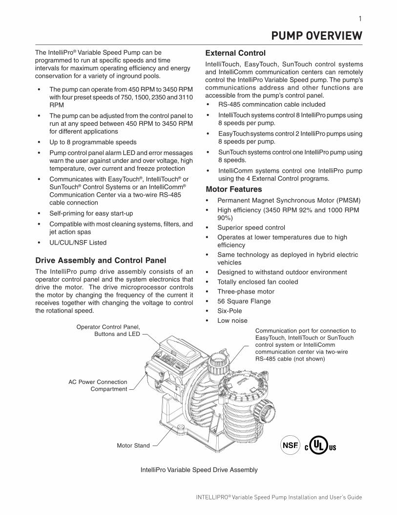
IntelliProVariableSpeedDriveAssembly
MotorStand
OperatorControlPanel,ButtonsandLED
ACPowerConnectionCompartment
Communication port for connection to EasyTouch, IntelliTouch or SunTouch control system or IntelliComm communication center via two-wire RS-485cable(notshown)
INTELLIPRO® Variable Speed Pump Installation and User’s Guide
2
INTELLIPRO® Variable Speed Pump Installation and User’s Guide
OnlyaqualifiedplumbingprofessionalshouldinstalltheIntelliPro®VariableSpeedPump.Referto“Pump Warning And Safety Instructions” on pages ii - iii for additional installation and safety information.
INSTALLATION
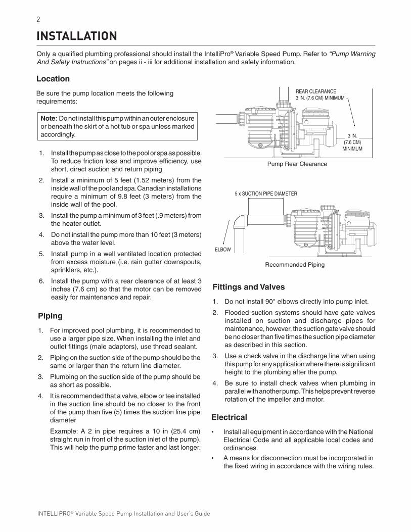
PumpRearClearance
REAR CLEARANCE 3 IN. (7.6 CM) MINIMUM
3 IN.(7.6 CM)
MINIMUM
RecommendedPiping
5 x SUCTION PIPE DIAMETER
ELBOW
Electrical
• InstallallequipmentinaccordancewiththeNationalElectrical Code and all applicable local codes and ordinances.
• Ameansfordisconnectionmustbeincorporatedinthe fixed wiring in accordance with the wiring rules.
Location
Be sure the pump location meets the following requirements:
Piping
1. Forimprovedpoolplumbing,itisrecommendedtouse a larger pipe size. When installing the inlet and outletfittings(maleadaptors),usethreadsealant.
2. Piping on the suction side of the pump should be the same or larger than the return line diameter.
3. Plumbing on the suction side of the pump should be as short as possible.
4. It is recommended that a valve, elbow or tee installed in the suction line should be no closer to the front ofthepumpthanfive(5)timesthesuctionlinepipediameter
Example: A 2 in pipe requires a 10 in (25.4 cm)straightruninfrontofthesuctioninletofthepump).This will help the pump prime faster and last longer.
Fittings and Valves
1. Donotinstall90°elbowsdirectlyintopumpinlet.
2. Floodedsuctionsystemsshouldhavegatevalvesinstalled on suction and discharge pipes for maintenance, however, the suction gate valve should be no closer than five times the suction pipe diameter as described in this section.
3. Useacheckvalveinthedischargelinewhenusingthis pump for any application where there is significant height to the plumbing after the pump.
4. Besure to install checkvalveswhenplumbing inparallel with another pump. This helps prevent reverse rotation of the impeller and motor.
1. Install the pump as close to the pool or spa as possible. To reduce friction loss and improve efficiency, use short, direct suction and return piping.
2. Installaminimumof5feet(1.52meters)fromtheinside wall of the pool and spa. Canadian installations requireaminimumof9.8feet(3meters)fromtheinside wall of the pool.
3. Installthepumpaminimumof3feet(.9meters)fromthe heater outlet.
4. Donotinstallthepumpmorethan10feet(3meters)above the water level.
5. Install pump in a well ventilated location protected fromexcessmoisture(i.e.raingutterdownspouts,sprinklers,etc.).
6. Installthepumpwitharearclearanceofatleast3inches(7.6cm)sothatthemotorcanberemovedeasily for maintenance and repair.
Note: Donotinstallthispumpwithinanouterenclosureorbeneaththeskirtofahottuborspaunlessmarkedaccordingly.
3
INTELLIPRO® Variable Speed Pump Installation and User’s GuideINTELLIPRO® Variable Speed Pump Installation and User’s Guide
Electrical Wiring InstallationTo connect the IntelliPro®VariableSpeedPumptoanACpowersource:
1. Besureallelectricalbreakersandswitchesareturnedoff before wiring motor.
2. Besurethatthesupplylinevoltagematchesthemotorvoltagelistedonthemotorplate(example230VACor115VAC).Iftheydonotmatch,permanentmotordamage may occur.
3. Forwiringsizesandgeneralguidelinesforproperelectrical installation, please follow the specifications definedintheNationalElectricCodeandanylocalcodes as required.
4. Usestrainreliefandbesureallelectricalconnectionsare clean and tight.
5. Cutthewirestotheappropriatelengthsotheydonot overlap or touch when connected.
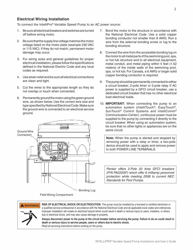
6. Permanentlygroundthemotorusingthegreengroundwire,asshownbelow.UsethecorrectwiresizeandtypespecifiedbyNationalElectricalCode.Makesurethe ground wire is connected to an electrical service ground.
7. Bond the motor to the structure in accordance with the National Electrical Code. Use a solid copperbondingconductornotsmallerthan8AWG.Runawire from the external bonding screw or lug to the bonding structure.
8. Connectthewirefromtheaccessiblebondinglugonthe motor to all metal parts of the swimming pool, spa, or hot tub structure and to all electrical equipment, metalconduit,andmetalpipingwithin5feet(1.52meters)of the insidewallsof theswimmingpool,spa,orhottub.ForCanada,a6AWGorlargersolidcopper bonding conductor is required.
9. Thepumpshouldbepermanentlyconnectedtoeitheracircuitbreaker,2-poletimeror2-polerelay.IfACpowerissuppliedbyaGFCIcircuitbreaker,useadedicatedcircuitbreakerthathasnootherelectricalload electrical loads.
10. IMPORTANT: When connecting the pump to an automation system (IntelliTouch®, EasyTouch®, SunTouch® Control Systems and IntelliComm®
CommunicationCenter), continuous power must be supplied to the pump by connecting it directly to the circuitbreaker.Whenusinganautomationsystem,be sure that no other lights or appliances are on the same circuit.
Note: When the pump is started and stopped by removing power with a relay or timer, a two-pole device should be used to apply and remove power tobothPOWERLINETERMINALS.
RISK OF ELECTRICAL SHOCK OR ELECTROCUTION. This pump must be installed by a licensed or certified electrician or a qualified service professional in accordance with the National Electrical Code and all applicable local codes and ordinances. Improper installation will create an electrical hazard which could result in death or serious injury to users, installers, or others due to electrical shock, and may also cause damage to property.
Always disconnect power to the pump at the circuit breaker before servicing the pump. Failure to do so could result in death or serious injury to service people, users or others due to electric shock. Read all servicing instructions before working on the pump.
Pentair offers 2-Pole 20 Amp GFCI breakers (P/N PA220GF) which offer 6 milliamp personnel protection while meeting 2008 to current NEC Standards for Pool Pumps.
GroundWireConnection
BondingLug
FieldWiringCompartment
INTELLIPRO® Variable Speed Pump Installation and User’s Guide
4
INTELLIPRO® Variable Speed Pump Installation and User’s Guide
OPERATING THE PUMP
This pump is shipped with Priming mode ENABLED. Unless the Priming settings are changed in the menu, be aware that the pump will speed up to the maximum speed when the pump is powered on for the first time, and the start/stop button is pressed. To change the maximum speed of the pump, refer to page 9. Before turning the pump ON, be sure the following conditions are met: 1. Open filter air relief valve. 2. Open valves. 3. Pool return is completely open and clear of any blockages. 4. Water in the pump basket.5. Stand clear of the filter or other pressurized vessels.
Do not add chemicals to the system directly in front of pump suction. Adding undiluted chemicals may damage the pump and will void the warranty.
This is a variable speed pump. Typically the lower speeds are used for filtration and heating. The higher speeds can be used for spa jets, water features, and priming.
NOTE: Speed 1 is the default filtration speed. When setting up the IntelliPro® Variable Speed Pump, the user must set the pump’s internal clock and establish an operation schedule by following the steps in this manual. Please refer to user’s guide sections: ‘Set Time’ (page 8) and ‘Set Speeds 1-8 in Schedule Mode’ (page 12) to schedule a time to run the pump.
Followthestepsbelowtoprimethepumpforstartup:
1. PressStart/Stop tostopthepump.Disconnectthe pump main power supply and communication cable.
2. Closeallgatevalvesinsuctionanddischarge pipes.Relieveallpressurefromthesystem.
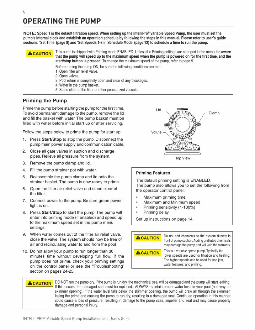
3. Removethepumpclampandlid.
4. Fillthepumpstrainerpotwithwater.
5. Reassemblethepumpclampandlidontothe strainerbasket.Thepumpisnowreadytoprime.
6. Openthefilterairreliefvalveandstandclearof the filter.
7. Connect power to the pump. Be sure green power light is on.
8. PressStart/Stop to start the pump. The pump will enterintoprimingmode(ifenabled)andspeedup to the maximum speed set in the pump menu settings.
9. Whenwatercomesoutofthefilterairreliefvalve, close the valve. The system should now be free of air and recirculating water to and from the pool
10. Donotallowyourpumptorunlongerthan30minutes time without developing full flow. If the pumpdoesnotprime,checkyourprimingsettingson the control panel or see the “Troubleshooting” sectiononpages24-25.
Priming the PumpPrime the pump before starting the pump for the first time. To avoid permanent damage to the pump, remove the lid andfillthebasketwithwater.Thepumpbasketmustbefilled with water before initial start up or after servicing.
DO NOT run the pump dry. If the pump is run dry, the mechanical seal will be damaged and the pump will start leaking. If this occurs, the damaged seal must be replaced. ALWAYS maintain proper water level in your pool (half way up skimmer opening). If the water level falls below the skimmer opening, the pump will draw air through the skimmer, losing the prime and causing the pump to run dry, resulting in a damaged seal. Continued operation in this manner could cause a loss of pressure, resulting in damage to the pump case, impeller and seal and may cause property damage and personal injury.
LidClamp
Top View
Volute
Priming Features
ThedefaultprimingsettingisENABLED.The pump also allows you to set the following from the operator control panel:
• Maximumprimingtime• MaximumandMinimumspeed• Primingsensitivity(1-100%)• Priming delay
Setupinstructionsonpage14.
5
INTELLIPRO® Variable Speed Pump Installation and User’s GuideINTELLIPRO® Variable Speed Pump Installation and User’s Guide
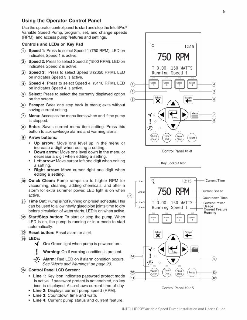
ControlPanel#1-8
12:15
750 RPMT 0.00 150 WATTSRunning Speed 1
Speed 1
Speed 2
Speed 3
Speed 4
QuickClean
TimeOut
15
Line 1
Line 2
Line 3
Line 4
9
13
12
10
11
14
12:15
750 RPMT 0.00 150 WATTSRunning Speed 1
1
5
2
6
8
4
3
7
Speed 1
Speed 2
Speed 3
Speed 4
QuickClean
TimeOut
ControlPanel#9-15
KeyLockoutIcon
Current Speed
Countdown Time
CurrentFeatureRunning
Current Time
Current Power Usage
Using the Operator Control PanelUsetheoperatorcontrolpaneltostartandstoptheIntelliPro® Variable Speed Pump, program, set, and change speeds (RPM),andaccesspumpfeaturesandsettings.
Speed 1: PresstoselectSpeed1(750RPM).LEDonindicatesSpeed1isactive.
Speed 2:PresstoselectSpeed2(1500RPM).LEDonindicatesSpeed2isactive.
Speed 3:PresstoselectSpeed3(2350RPM).LEDonindicatesSpeed3isactive.
Speed 4:PresstoselectSpeed4(3110RPM).LEDonindicatesSpeed4isactive.
Select: Press to select the currently displayed option on the screen.
Escape:Goesonestepback inmenu;exitswithoutsaving current setting.
Menu:Accessesthemenuitemswhenandifthepumpis stopped.
Enter: Saves current menu item setting. Press this buttontoacknowledgealarmsandwarningalerts.
Arrow buttons: • Up arrow: Move one level up in the menu or
increase a digit when editing a setting.• Down arrow:Moveoneleveldowninthemenuor
decrease a digit when editing a setting.• Left arrow: Movecursorleftonedigitwhenediting
a setting.• Right arrow: Move cursor right one digit when
editing a setting.
Controls and LEDs on Key Pad
Quick Clean: Pump ramps up to higher RPM forvacuuming, cleaning, adding chemicals, and after a stormforextraskimmerpower.LEDlight isonwhenactive.
Time Out: Pump is not running on preset schedule. This canbeusedtoallownewlygluedpipejointstimetodrybeforecirculationofwaterstarts.LEDisonwhenactive.
Start/Stop button: To start or stop the pump. When LEDison,thepumpisrunningorinamodetostartautomatically.
Reset button:Resetalarmoralert.
LEDs: On:Greenlightwhenpumpispoweredon.
Warning: Onifwarningconditionispresent.
Alarm: RedLEDonifalarmconditionoccurs. See “Alerts and Warnings” on page 23.
Control Panel LCD Screen:
• Line 1: Key icon indicates password protect mode isactive.Ifpasswordprotectisnotenabled,nokeyiconisdisplayed.Alsoshowscurrenttimeofday.
• Line 2:Displayscurrentpumpspeed(RPM).• Line 3: Countdown time and watts• Line 4: Current pump status and current feature.
5
1
2
3
4
6
7
8
9
10
11
12
13
14
15
INTELLIPRO® Variable Speed Pump Installation and User’s Guide
6
INTELLIPRO® Variable Speed Pump Installation and User’s Guide
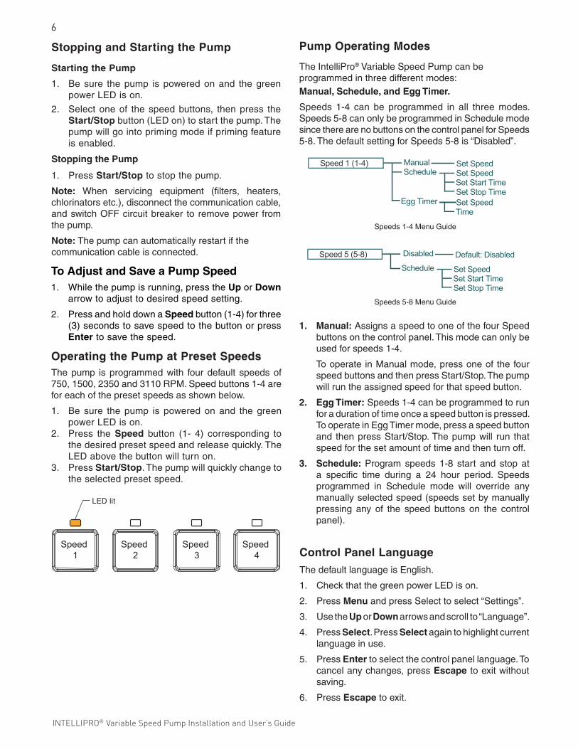
Speed 1 (1-4) Manual Schedule
Egg Timer
Set Speed - Default: MANUAL Set Speed Set Start Time Set Stop Time Set Speed Time
Speeds1-4MenuGuide
Speeds5-8MenuGuide
Stopping and Starting the Pump
Starting the Pump
1. Besure thepump ispoweredonand thegreenpowerLEDison.
2. Selectoneof thespeedbuttons, thenpress theStart/Stopbutton(LEDon)tostartthepump.Thepump will go into priming mode if priming feature is enabled.
Stopping the Pump
1. PressStart/Stop to stop the pump.
Note: When servicing equipment (filters, heaters,chlorinatorsetc.),disconnectthecommunicationcable,andswitchOFFcircuitbreaker toremovepower fromthe pump.
Note: The pump can automatically restart if the communication cable is connected.
Operating the Pump at Preset SpeedsThe pump is programmed with four default speeds of 750,1500,2350and3110RPM.Speedbuttons1-4arefor each of the preset speeds as shown below.
1. Be sure the pump is powered on and the greenpowerLEDison.
2. Press the Speed button (1- 4) corresponding tothedesiredpresetspeedandreleasequickly.TheLEDabovethebuttonwillturnon.
3. PressStart/Stop.Thepumpwillquicklychangetothe selected preset speed.
To Adjust and Save a Pump Speed1. While the pump is running, press the Up or Down
arrowtoadjusttodesiredspeedsetting.
2. Press and hold down a Speedbutton(1-4)forthree(3)secondstosavespeedtothebuttonorpressEnter to save the speed.
LEDlit
Speed 1
Speed 2
Speed 3
Speed 4
LED lit
Pump Operating Modes
The IntelliPro® Variable Speed Pump can be programmed in three different modes: Manual, Schedule, and Egg Timer.
Speeds 1-4 can be programmed in all three modes.Speeds5-8canonlybeprogrammedinSchedulemodesince there are no buttons on the control panel for Speeds 5-8.ThedefaultsettingforSpeeds5-8is“Disabled”.
Speed 5 (5-8)
Schedule Set Speed Set Start Time Set Stop Time
Disabled Default: Disabled
1. Manual:AssignsaspeedtooneofthefourSpeedbuttons on the control panel. This mode can only be usedforspeeds1-4.
TooperateinManualmode,pressoneofthefourspeedbuttonsandthenpressStart/Stop.Thepumpwill run the assigned speed for that speed button.
2. Egg Timer:Speeds1-4canbeprogrammedtorunfor a duration of time once a speed button is pressed. To operate in Egg Timer mode, press a speed button and thenpressStart/Stop.Thepumpwill run thatspeed for the set amount of time and then turn off.
3. Schedule: Program speeds 1-8 start and stop ata specific time during a 24 hour period. Speedsprogrammed in Schedule mode will override any manuallyselectedspeed(speedssetbymanuallypressing any of the speed buttons on the control panel).
Control Panel LanguageThe default language is English.
1. CheckthatthegreenpowerLEDison.
2. Press Menu and press Select to select “Settings”.
3. UsetheUp or Downarrowsandscrollto“Language”.
4. Press Select. Press Select again to highlight current language in use.
5. Press Enter to select the control panel language. To cancel any changes, press Escape to exit without saving.
6. Press Escape to exit.
7
INTELLIPRO® Variable Speed Pump Installation and User’s GuideINTELLIPRO® Variable Speed Pump Installation and User’s Guide
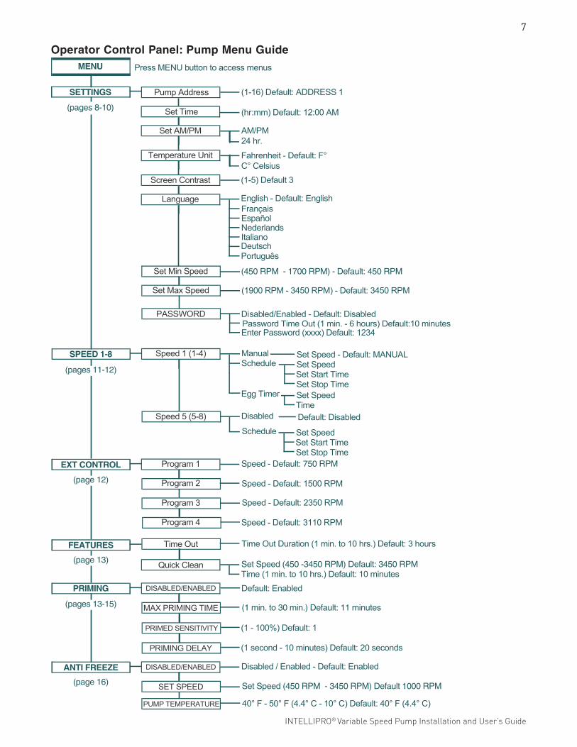
Operator Control Panel: Pump Menu Guide
Press MENU button to access menus
(1-16) Default: ADDRESS 1
(hr:mm) Default: 12:00 AM
AM/PM24 hr.
Fahrenheit - Default: F°C° Celsius(1-5) Default 3
(450 RPM - 1700 RPM) - Default: 450 RPM
(1900 RPM - 3450 RPM) - Default: 3450 RPM
Password Time Out (1 min. - 6 hours) Default:10 minutes Disabled/Enabled - Default: Disabled
Enter Password (xxxx) Default: 1234
Manual Schedule
Egg Timer
Set Speed - Default: MANUAL Set Speed Set Start Time Set Stop Time Set Speed Time
Speed - Default: 750 RPM
Speed - Default: 1500 RPM
Set Speed (450 -3450 RPM) Default: 3450 RPM Time (1 min. to 10 hrs.) Default: 10 minutes
Time Out Duration (1 min. to 10 hrs.) Default: 3 hours
(1 min. to 30 min.) Default: 11 minutes
Disabled / Enabled - Default: Enabled
Speed - Default: 2350 RPM
Speed - Default: 3110 RPM
English - Default: English
Schedule Set Speed Set Start Time Set Stop Time
Disabled Default: Disabled
Default: Enabled
(1 - 100%) Default: 1
(1 second - 10 minutes) Default: 20 seconds
40° F - 50° F (4.4° C - 10° C) Default: 40° F (4.4° C)
Set Speed (450 RPM - 3450 RPM) Default 1000 RPM
SETTINGS
MENU
SPEED 1-8
EXT CONTROL
FEATURES
PRIMING
ANTI FREEZE
FrançaisEspañolNederlandsItaliano
PortuguêsDeutsch
Set AM/PM
Pump Address
Set Time
Temperature Unit
Screen Contrast
Language
Set Min Speed
Set Max Speed
PASSWORD
Speed 1 (1-4)
Program 1
Program 2
Quick Clean
Time Out
DISABLED/ENABLED
MAX PRIMING TIME
Program 3
Program 4
Speed 5 (5-8)
PRIMED SENSITIVITY
PRIMING DELAY
DISABLED/ENABLED
SET SPEED
PUMP TEMPERATURE
(pages 8-10)
(pages 11-12)
(page 12)
(page 13)
(pages 13-15)
(page 16)
INTELLIPRO® Variable Speed Pump Installation and User’s Guide
8
INTELLIPRO® Variable Speed Pump Installation and User’s Guide
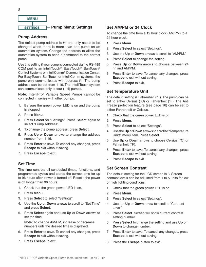
Set Temperature UnitThe default setting is Fahrenheit(°F). The pump can be set toeitherCelsius (°C)orFahrenheit (°F).TheAntiFreezeprotectionfeature(seepage16)canbesettoeitherFahrenheitorCelsius.
1. CheckthatthegreenpowerLEDison.
2. Press Menu.
3. Press Select to select “Settings”.
4. UsetheUp or Down arrows to scroll to “Temperature Units”menuitem.PressSelect.
5. UseUp or DownarrowstochooseCelsius(°C)orFahrenheit(°F).
6. Press Enter to save. To cancel any changes, press Escape to exit without saving.
7. Press Escape to exit.
Pump Menu: Settings
Pump AddressThedefaultpumpaddressis#1andonlyneedstobechanged when there is more than one pump on an automation system. Change the address to allow the automation system to send a command to the correct pump.
UsethissettingifyourpumpisconnectedviatheRS-485COMporttoanIntelliTouch®, EasyTouch®, SunTouch®
Control Systems or IntelliComm® Communication Center. ForEasyTouch,SunTouchorIntelliCommsystems,thepumponlycommunicateswithaddress#1.Thepumpaddresscanbesetfrom1-16.TheIntelliTouchsystemcancommunicateonlytofour(1-4)pumps.
Note: IntelliPro® Variable Speed Pumps cannot be connected in series with other pumps.
1. BesurethegreenpowerLEDisonandthepumpis stopped.
2. Press Menu.
3. Press Select for “Settings”. Press Select again to select“PumpAddress”.
4. To change the pump address, press Select.
5. Press Up or Down arrows to change the address numberfrom1-16.
6. Press Enter to save. To cancel any changes, press Escape to exit without saving.
7. Press Escape to exit.
Set TimeThe time controls all scheduled times, functions, and programmed cycles and stores the correct time for up to96hoursafterpoweristurnedoff.Resetifthepowerisofflongerthan96hours.
1. CheckthatthegreenpowerLEDison.
2. Press Menu.
3. Press Select to select “Settings”.
4. UsetheUp or Down arrows to scroll to “Set Time” and press Select.
5. Press Select again and use Up or Down arrows to set the time.
Note: TochangeAM/PM,increaseordecreasenumbers until the desired time is displayed.
6. Press Enter to save. To cancel any changes, press Escape to exit without saving.
7. Press Escape to exit.
Set AM/PM or 24 ClockTochangethetimefroma12hourclock(AM/PM)toa24hourclock:
1. Press Menu.
2. Press Select to select “Settings”.
3. UsetheUp or Downarrowstoscrollto“AM/PM.”
4. Press Select to change the setting.
5. Press Up or Downarrows tochoosebetween24hr.andAM/PM.
6. Press Enter to save. To cancel any changes, press Escape to exit without saving.
7. Press Escape to exit.
MENU
SETTINGS (1-16) Default: ADDRESS 1
(hr:mm) Default: 12:00 AM
Set AM/PM AM/PM24 hr.
Fahrenheit - Default: F°C° Celsius(1-5) Default 3
(450 RPM - 1700 RPM) - Default: 450 RPM
(1900 RPM - 3450 RPM) - Default: 3450 RPM
Pump Address
Set Time
Temperature Unit
Screen Contrast
Language
Set Min Speed
Set Max Speed
PASSWORD Password Time Out (1 min. - 6 hours) Default:10 minutes Disabled/Enabled - Default: Disabled
Enter Password (xxxx) Default: 1234
English - Default: English
Set Screen ContrastThedefaultsettingfortheLCDscreenis3.Screencontrastlevelscanbeadjustedfrom1to5unitsforlowor high lighting conditions.
1. CheckthatthegreenpowerLEDison.
2. Press Menu.
3. Press Select to select “Settings”.
4. UsetheUp or Down arrow to scroll to “Contrast Level”.
5. Press Select. Screen will show current contrast setting number.
6. Press Select to change the setting and use Up or Down to change number.
7. Press Enter to save. To cancel any changes, press Escape to exit without saving.
8. Press the Escape button to exit.
9
INTELLIPRO® Variable Speed Pump Installation and User’s GuideINTELLIPRO® Variable Speed Pump Installation and User’s Guide
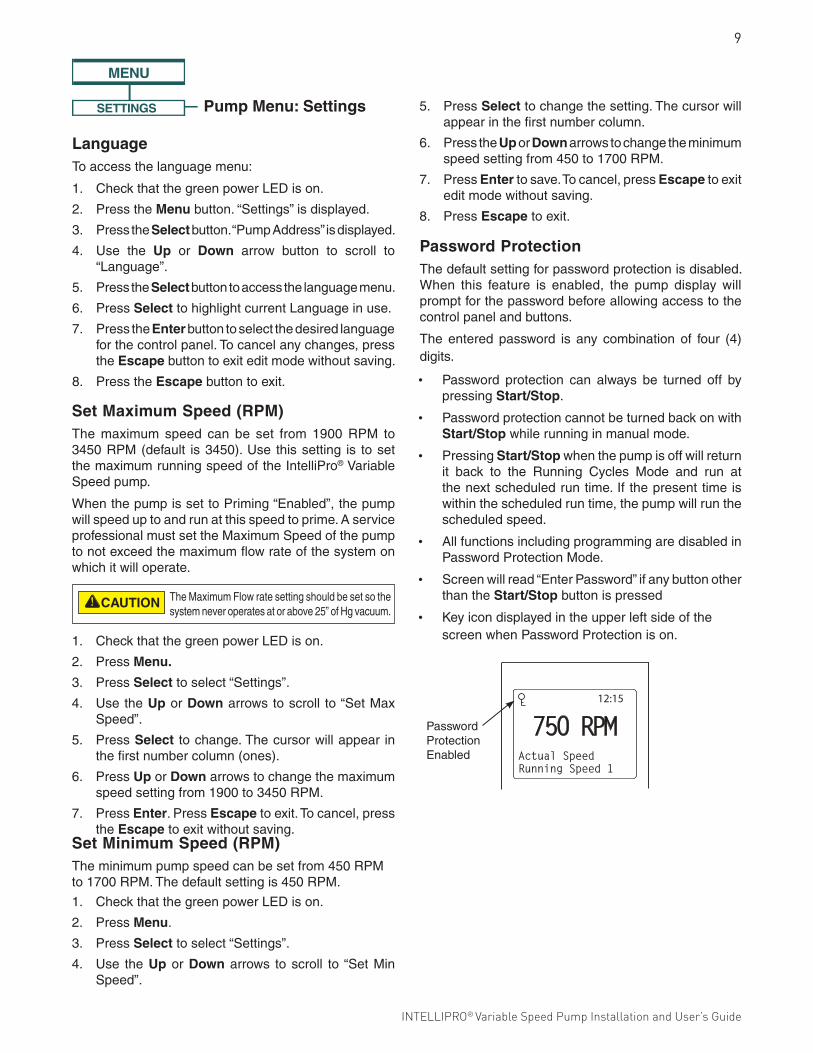
Set Maximum Speed (RPM)The maximum speed can be set from 1900 RPM to3450RPM(default is3450).Use thissetting is tosetthe maximum running speed of the IntelliPro® Variable Speed pump.
When the pump is set to Priming “Enabled”, the pump willspeeduptoandrunatthisspeedtoprime.AserviceprofessionalmustsettheMaximumSpeedofthepumpto not exceed the maximum flow rate of the system on which it will operate.
1. CheckthatthegreenpowerLEDison.
2. Press Menu.
3. Press Select to select “Settings”.
4. UsetheUp or Downarrowstoscroll to“SetMaxSpeed”.
5. Press Select to change. The cursor will appear in thefirstnumbercolumn(ones).
6. Press Up or Down arrows to change the maximum speedsettingfrom1900to3450RPM.
7. Press Enter. Press Escape to exit. To cancel, press the Escape to exit without saving.
The Maximum Flow rate setting should be set so the system never operates at or above 25” of Hg vacuum.
Pump Menu: Settings
MENU
SETTINGS (1-16) Default: ADDRESS 1
(hr:mm) Default: 12:00 AM
Set AM/PM AM/PM24 hr.
Fahrenheit - Default: F°C° Celsius(1-5) Default 3
(450 RPM - 1700 RPM) - Default: 450 RPM
(1900 RPM - 3450 RPM) - Default: 3450 RPM
Pump Address
Set Time
Temperature Unit
Screen Contrast
Language
Set Min Speed
Set Max Speed
PASSWORD Password Time Out (1 min. - 6 hours) Default:10 minutes Disabled/Enabled - Default: Disabled
Enter Password (xxxx) Default: 1234
English - Default: English
Set Minimum Speed (RPM)Theminimumpumpspeedcanbesetfrom450RPMto1700RPM.Thedefaultsettingis450RPM.
1. CheckthatthegreenpowerLEDison.
2. Press Menu.
3. Press Select to select “Settings”.
4. Use theUp or Downarrows toscroll to“SetMinSpeed”.
Password ProtectionThe default setting for password protection is disabled. When this feature is enabled, the pump display will prompt for the password before allowing access to the control panel and buttons.
The entered password is any combination of four (4)digits.
12:15
750 RPMActual SpeedRunning Speed 1
Password Protection Enabled
• Password protection can always be turned off by pressing Start/Stop.
• PasswordprotectioncannotbeturnedbackonwithStart/Stop while running in manual mode.
• Pressing Start/Stop when the pump is off will return it back to the Running Cycles Mode and run atthe next scheduled run time. If the present time is within the scheduled run time, the pump will run the scheduled speed.
• AllfunctionsincludingprogrammingaredisabledinPasswordProtectionMode.
• Screen will read “Enter Password” if any button other than the Start/Stop button is pressed
• Key icon displayed in the upper left side of the screen when Password Protection is on.
5. Press Select to change the setting. The cursor will appear in the first number column.
6. Press the Up or Down arrows to change the minimum speedsettingfrom450to1700RPM.
7. Press Enter to save. To cancel, press Escape to exit edit mode without saving.
8. Press Escape to exit.
LanguageTo access the language menu:
1. CheckthatthegreenpowerLEDison.
2. Press the Menu button. “Settings” is displayed.
3. Press the Selectbutton.“PumpAddress”isdisplayed.
4. Use the Up or Down arrow button to scroll to “Language”.
5. Press the Select button to access the language menu.
6. Press SelecttohighlightcurrentLanguageinuse.
7. Press the Enter button to select the desired language for the control panel. To cancel any changes, press the Escape button to exit edit mode without saving.
8. Press the Escape button to exit.
INTELLIPRO® Variable Speed Pump Installation and User’s Guide
10
INTELLIPRO® Variable Speed Pump Installation and User’s Guide
Entering Password
1. Press any button (besides the speed button) toprompt the screen for a password.
2. To enter password, use the Left and Right arrows to move the cursor and the Up and Down arrow button to scroll through the digit then press Enter to confirm.
Setting Password1. CheckthatthegreenpowerLEDison.
2. Press Menu. Press Select to select “Settings”.
3. UsetheUp or Down arrow to scroll to “Password”.
4. Press Select. Thedefaultsettingis“Disabled”.
5. Press Up or Down arrow to change the setting to “Enabled” and press Enter to save.
6. Press the Down arrow. “Password Timeout” is displayed.
7. Thefactorydefaulttimeis10minutes.Thismeansthe IntelliPro® Variable Speed Pump will go into PasswordProtectionmode10minutesafterthelastcontrolpanelkeyispressed.
8. Press Selecttochangetimesettingfrom1minuteto6hoursandpressEnter to save.
9. Press Down arrow and then press Select on “Enter Password” to change the setting.
10. Press the Left or Right arrows to move cursor and press Up or Down arrow to change password number to desired setting.
11. Press Enter to save. To cancel any changes, press Escape to exit without saving.
Pump Menu: Settings
MENU
SETTINGS (1-16) Default: ADDRESS 1
(hr:mm) Default: 12:00 AM
Set AM/PM AM/PM24 hr.
Fahrenheit - Default: F°C° Celsius(1-5) Default 3
(450 RPM - 1700 RPM) - Default: 450 RPM
(1900 RPM - 3450 RPM) - Default: 3450 RPM
Pump Address
Set Time
Temperature Unit
Screen Contrast
Language
Set Min Speed
Set Max Speed
PASSWORD Password Time Out (1 min. - 6 hours) Default:10 minutes Disabled/Enabled - Default: Disabled
Enter Password (xxxx) Default: 1234
English - Default: English
11
INTELLIPRO® Variable Speed Pump Installation and User’s GuideINTELLIPRO® Variable Speed Pump Installation and User’s Guide
Pump Menu: Speeds 1-8SPEED 1-8 Speed 1 (1-4) Manual Schedule
Egg Timer
Set Speed - Default: MANUAL Set Speed Set Start Time Set Stop Time Set Speed Time
Speed 5 (5-8)
Schedule Set Speed Set Start Time Set Stop Time
Disabled Default: Disabled
MENU
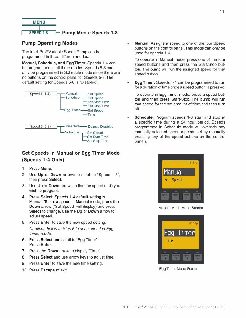
Pump Operating Modes
The IntelliPro® Variable Speed Pump can be programmed in three different modes:
Manual, Schedule, and Egg Timer.Speeds1-4canbeprogrammedinallthreemodes.Speeds5-8canonly be programmed in Schedule mode since there are nobuttonsonthecontrolpanelforSpeeds5-8.ThedefaultsettingforSpeeds5-8is“Disabled”.
Set Speeds in Manual or Egg Timer Mode (Speeds 1-4 Only)
1. Press Menu.
2. UseUp or Down arrows toscroll to“Speed1-8”,then press Select.
3. UseUp or Downarrowstofindthespeed(1-4)youwish to program.
4. Press Select. Speeds1-4defaultsettingisManual.TosetaspeedinManualmode,presstheDownarrow(“SetSpeed”willdisplay)andpressSelect tochange.UsetheUp or Down arrow to adjustspeed.
5. Press Enter to save the new speed setting.
Continue below to Step 6 to set a speed in Egg Timer mode.
6. Press Select and scroll to “Egg Timer”. Press Enter.
7. Press the Down arrow to display “Time”.
8. Press Select andusearrowkeystoadjusttime.
9. Press Enter to save the new time setting.
10. Press Escape to exit.
Speed 1 (1-4) Manual Schedule
Egg Timer
Set Speed - Default: MANUAL Set Speed Set Start Time Set Stop Time Set Speed Time
Speed 5 (5-8)
Schedule Set Speed Set Start Time Set Stop Time
Disabled Default: Disabled
• Manual:AssignsaspeedtooneofthefourSpeedbuttons on the control panel. This mode can only be usedforspeeds1-4.
TooperateinManualmode,pressoneofthefourspeedbuttonsand thenpress theStart/Stopbut-ton. The pump will run the assigned speed for that speed button.
• Egg Timer: Speeds1-4canbeprogrammedtorunfor a duration of time once a speed button is pressed.
To operate in Egg Timer mode, press a speed but-ton and then press Start/Stop.The pump will runthat speed for the set amount of time and then turn off.
• Schedule: Program speeds 1-8 start and stop ata specific time during a 24 hour period. Speedsprogrammed in Schedule mode will override any manuallyselectedspeed(speedssetbymanuallypressing any of the speed buttons on the control panel).
12:15p
Egg TimerTime
12:15p
ManualSet Speed
ManualModeMenuScreen
EggTimerMenuScreen
INTELLIPRO® Variable Speed Pump Installation and User’s Guide
12
INTELLIPRO® Variable Speed Pump Installation and User’s Guide
Pump Menu: Speeds 1-8SPEED 1-8 Speed 1 (1-4) Manual Schedule
Egg Timer
Set Speed - Default: MANUAL Set Speed Set Start Time Set Stop Time Set Speed Time
Speed 5 (5-8)
Schedule Set Speed Set Start Time Set Stop Time
Disabled Default: Disabled
MENU
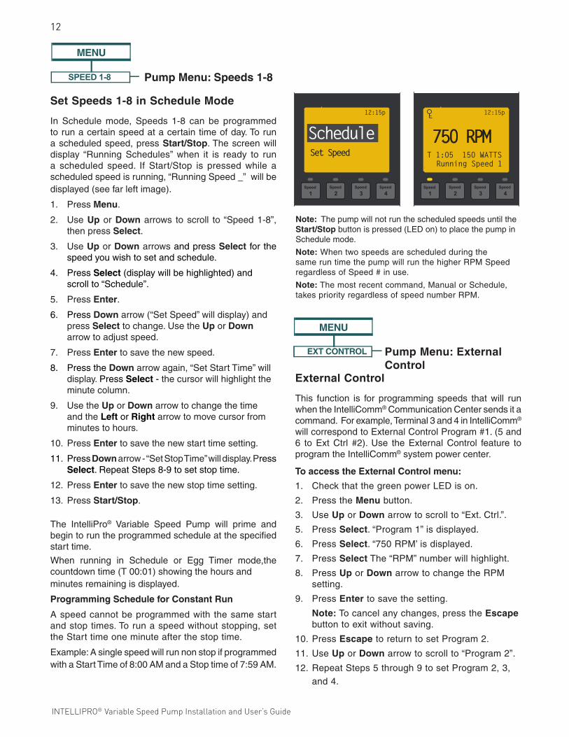
Set Speeds 1-8 in Schedule Mode
In Schedule mode, Speeds 1-8 can be programmedto run a certain speed at a certain time of day. To run a scheduled speed, press Start/Stop. The screen will display “Running Schedules” when it is ready to runa scheduled speed. If Start/Stop is pressed while ascheduledspeedisrunning,“RunningSpeed_”willbedisplayed(seefarleftimage).
1. Press Menu.
2. UseUp or Downarrows toscroll to“Speed1-8”,then press Select.
3. UseUp or Down arrows and press Select for the speed you wish to set and schedule.
4. Press Select (displaywillbehighlighted)andscroll to “Schedule”.
5. Press Enter.
6. Press Downarrow(“SetSpeed”willdisplay)andpress Select tochange.UsetheUp or Down arrowtoadjustspeed.
7. Press Enter to save the new speed.
8. Press the Down arrow again, “Set Start Time” will display. Press Select - the cursor will highlight the minute column.
9. UsetheUp or Down arrow to change the time and the Left or Right arrow to move cursor from minutes to hours.
10. Press Enter to save the new start time setting.
11. Press Down arrow - “Set Stop Time” will display. Press Select.RepeatSteps8-9tosetstoptime.
12. Press Enter to save the new stop time setting.
13. Press Start/Stop.
The IntelliPro® Variable Speed Pump will prime and begin to run the programmed schedule at the specified start time.
When running in Schedule or Egg Timer mode,the countdowntime(T00:01)showingthehoursandminutes remaining is displayed.
12:15p
Set Speed
Schedule
Note: The pump will not run the scheduled speeds until the Start/Stopbuttonispressed(LEDon)toplacethepumpinSchedule mode.
Note: When two speeds are scheduled during the sameruntimethepumpwillrunthehigherRPMSpeedregardless of Speed # in use.
Note: Themostrecentcommand,ManualorSchedule,takespriorityregardlessofspeednumberRPM.
Programming Schedule for Constant Run
Aspeedcannotbeprogrammedwith thesamestartand stop times. To run a speed without stopping, set the Start time one minute after the stop time.
Example:AsinglespeedwillrunnonstopifprogrammedwithaStartTimeof8:00AMandaStoptimeof7:59AM.
12:15p
750 RPMT 1:05 150 WATTSRunning Speed 1
EXT CONTROL Program 1 Speed - Default: 750 RPM
Speed - Default: 1500 RPMProgram 2
Program 3 Speed - Default: 2350 RPM
Speed - Default: 3110 RPMProgram 4
MENU
Pump Menu: External Control
External Control
This function is for programming speeds that will run when the IntelliComm® Communication Center sends it a command.Forexample,Terminal3and4inIntelliComm® willcorrespondtoExternalControlProgram#1.(5and6 to Ext Ctrl #2). Use the External Control feature toprogram the IntelliComm® system power center.
To access the External Control menu:
1. CheckthatthegreenpowerLEDison.
2. PresstheMenu button.
3. UseUp or Down arrow to scroll to “Ext. Ctrl.”.
5. PressSelect.“Program1”isdisplayed.
6. PressSelect.“750RPM’isdisplayed.
7. Press SelectThe“RPM”numberwillhighlight.
8. PressUp or Down arrowtochangetheRPMsetting.
9. PressEnter to save the setting.
Note: To cancel any changes, press the Escape button to exit without saving.
10. PressEscape toreturntosetProgram2.
11. UseUp or Down arrowtoscrollto“Program2”.
12. RepeatSteps5through9tosetProgram2,3,and4.
13
INTELLIPRO® Variable Speed Pump Installation and User’s GuideINTELLIPRO® Variable Speed Pump Installation and User’s Guide
Pump Menu: FeaturesFEATURES
Quick Clean Set Speed (1100 -3450 RPM) Default: 3450 RPM Time (1 min. to 10 hrs.) Default: 10 minutes
Time Out Duration (1 min. to 10 hrs.) Default: 3 hoursTime Out
MENU
Quick Clean
NOTE: Quick Clean is the only high-speed override feature of the IntelliPro® Variable Speed Pump.
This feature can be used to ramp the pump up to a higherRPMforvacuuming,cleaning,addingchemicals,afterastormforextraskimmingcapability.
Press the Quick Cleanbutton(LEDon)andthenStart/Stoptostart.WhentheQuickCleancycleisover,the pump will resume regular schedules and be in “RunningSchedule”mode.
To access the Quick Clean menu:
1. CheckthatthegreenpowerLEDison.
2. PressMenu.
3. UseUp or Downarrowstoscrollto“Features”,then press Select.
4. PresstheDown arrow and press Select for “QuickClean”.
7. Press Select to choose “Set Speed”.
8. PressSelect tohighlightthe“RPM”first(ones)column and change the speed.
9. UseUp or Down arrows to change the speed.
10. PressEnter to save the speed.
11. PresstheDown arrow again, and press Select for“TimeDuration”.
12. PressSelect to change the time. The cursor will highlight the minutes column.
13. UseUp or Down arrows to change the time from 1minuteto10hours.
14. PressEnter to save the time.
15. PressEscape to exit the menu.
Time Out
Thisfeaturecanbeusedtoallownewlygluedpipejointstime to dry before circulation of the pool water resumes. TheTimeOutfeaturekeepsthepumpfromrunningit’sprogrammed speeds.
OnceTimeOutisfinished,thepumpwillbein“RunningSchedule”mode, theStart/StopLEDwillbelit and ready to turn on at the next scheduled run time.
To access the Time Out menu:
1. CheckthatthegreenpowerLEDison.
2. PressMenu.
3. Use Up or Down arrows to scroll to “Features”,then press Select.
5. PressSelect to choose “Timeout”.
6. Then press Select again to choose “Timeout Duration”.
7. Press Select to change the time. The cursor will highlight the minutes column.
8. PresstheLeft arrow to move cursor to the hours column. Timeoutcanbesetfrom1minuteto10hours.
9. PressEnter to save the setting.
Note: To cancel any changes, press Escape to exit without saving.
10. PressEscape to exit the menu.
PRIMING DISABLED/ENABLED
(1 min. to 30 min. hrs.) Default: 11 minutesMAX PRIMING TIME
Disabled / Enabled - Default: Enabled
Default: Enabled
(1 - 100%) Default: 1PRIMED SENSITIVITY
(1 second - 10 minutes) Default: 20 secondsPRIMING DELAY
DISABLED/ENABLED
MENU
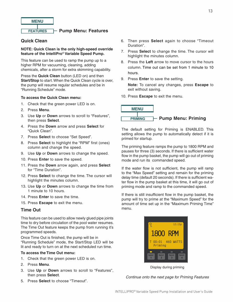
Pump Menu: Priming
The default setting for Priming is ENABLED. Thissetting allows the pump to automatically detect if it is primed for startup.
Theprimingfeaturerampsthepumpto1800RPMandpausesforthree(3)seconds.Ifthereissufficientwaterflowinthepumpbasket,thepumpwillgooutofprimingmode and run its commanded speed.
If the water flow is not sufficient, the pump will ramp tothe“MaxSpeed”settingandremainfortheprimingdelaytime(default20seconds).Ifthereissufficientwa-terflowinthepumpbasketatthistime,itwillgooutofpriming mode and ramp to the commanded speed.
Ifthereisstillinsufficientflowinthepumpbasket,thepumpwilltrytoprimeatthe“MaximumSpeed”fortheamountoftimesetupinthe“MaximumPrimingTime”menu.
Displayduringpriming
12:15p
1800 RPMT 00:01 460 WATTSPriming
Continue onto the next page for Priming Features
INTELLIPRO® Variable Speed Pump Installation and User’s Guide
14
INTELLIPRO® Variable Speed Pump Installation and User’s Guide
Setting Priming Features
1. PressMenu.
2. UseDown arrow to scroll to “Priming” and press Select.
3. Thefactorydefaultissettopriming“Enabled“.Todisable, press Select.
4. PressEnter if you have changed the setting - this will save the selection.
5. PresstheDownarrow-thescreenwillread“MaxPriming Time”.
6. Tochangefromfactorydefault,pressSelect. The cursor will highlight.
7. Use theUp or Down arrows to change the time from1minuteto30minutes.
8. PressEnter to save.
11. PresstheDown arrow - the screen will read “Primed Sensitivity”.Defaultis“1”
12. PressSelect to change the priming sensitivity. The cursor will highlight the number.
PRIMING DISABLED/ENABLED
(1 min. to 30 min. hrs.) Default: 11 minutesMAX PRIMING TIME
Disabled / Enabled - Default: Enabled
Default: Enabled
(1 - 100%) Default: 1PRIMED SENSITIVITY
(1 second - 10 minutes) Default: 20 secondsPRIMING DELAY
DISABLED/ENABLED
MENU
Pump Menu: Priming
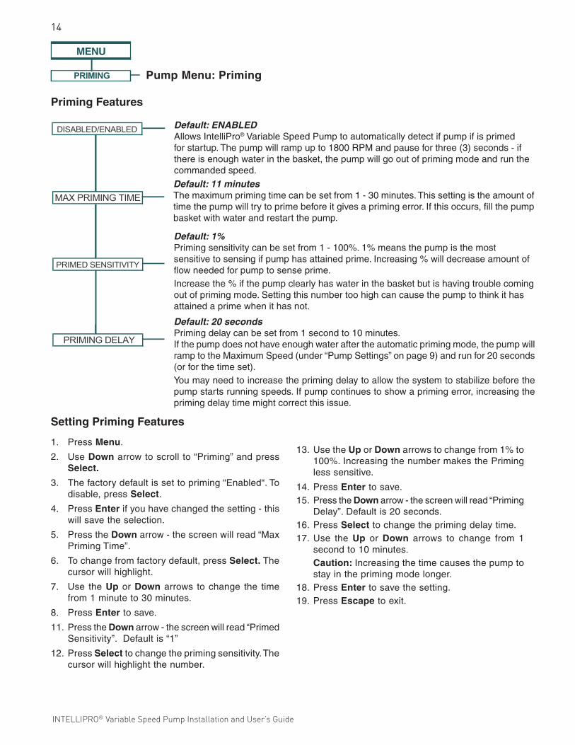
Priming Features
DISABLED/ENABLED
MAX PRIMING TIME
PRIMED SENSITIVITY
PRIMING DELAY
Default: ENABLEDAllowsIntelliPro® Variable Speed Pump to automatically detect if pump if is primed forstartup.Thepumpwillrampupto1800RPMandpauseforthree(3)seconds-ifthereisenoughwaterinthebasket,thepumpwillgooutofprimingmodeandrunthecommanded speed.
Default: 11 minutesThemaximumprimingtimecanbesetfrom1-30minutes.Thissettingistheamountoftime the pump will try to prime before it gives a priming error. If this occurs, fill the pump basketwithwaterandrestartthepump.
Default: 20 secondsPrimingdelaycanbesetfrom1secondto10minutes.If the pump does not have enough water after the automatic priming mode, the pump will ramptotheMaximumSpeed(under“PumpSettings”onpage9)andrunfor20seconds(orforthetimeset).You may need to increase the priming delay to allow the system to stabilize before the pump starts running speeds. If pump continues to show a priming error, increasing the priming delay time might correct this issue.
Default: 1%Primingsensitivitycanbesetfrom1-100%.1%meansthepumpisthemostsensitivetosensingifpumphasattainedprime.Increasing%willdecreaseamountofflow needed for pump to sense prime. Increasethe%ifthepumpclearlyhaswaterinthebasketbutishavingtroublecomingoutofprimingmode.Settingthisnumbertoohighcancausethepumptothinkithasattained a prime when it has not.
13. UsetheUp or Downarrowstochangefrom1%to100%.IncreasingthenumbermakesthePrimingless sensitive.
14. PressEnter to save. 15. PresstheDown arrow - the screen will read “Priming
Delay”.Defaultis20seconds.16. PressSelect to change the priming delay time.17. Use the Up or Down arrows to change from 1
secondto10minutes. Caution: Increasing the time causes the pump to
stay in the priming mode longer.18. PressEnter to save the setting. 19. PressEscape to exit.
15
INTELLIPRO® Variable Speed Pump Installation and User’s GuideINTELLIPRO® Variable Speed Pump Installation and User’s Guide
P
PRIMING DISABLED/ENABLED
(1 min. to 30 min. hrs.) Default: 11 minutesMAX PRIMING TIME
Disabled / Enabled - Default: Enabled
Default: Enabled
(1 - 100%) Default: 1PRIMED SENSITIVITY
(1 second - 10 minutes) Default: 20 secondsPRIMING DELAY
DISABLED/ENABLED
MENU
Pump Menu: Priming
When the IntelliPro® Variable Speed Pump is connected to an automation control system, (IntelliTouch®, EasyTouch® or SunTouch® Control Systems), the priming feature on the pump cannot be disabled by the external automation control system only. It must also be disabled on the pump itself.
If priming is enabled on start up, the pump responds to its internal settings before responding to commands from an automation control system.
If the pump is connected to an automation control system and priming is not desired, disable the priming feature on both the pump and the automation control system.
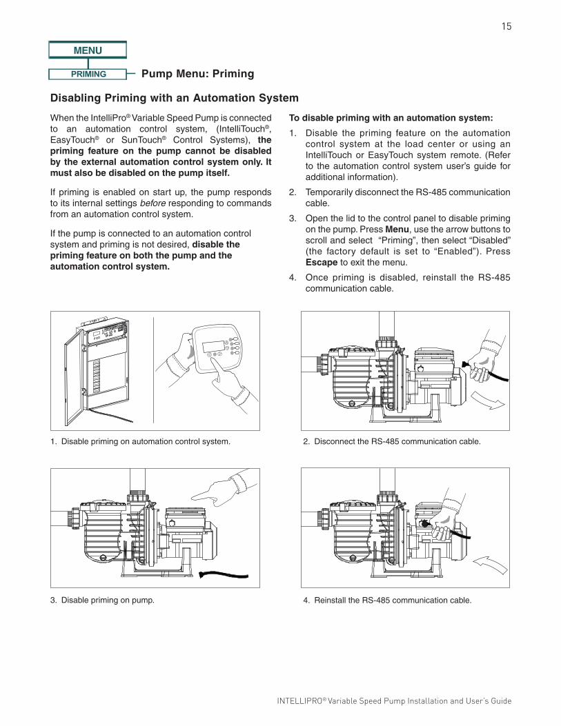
To disable priming with an automation system:
1. Disable the priming feature on the automationcontrol system at the load center or using an IntelliTouch or EasyTouch system remote. (Referto the automation control system user’s guide for additionalinformation).
2. TemporarilydisconnecttheRS-485communicationcable.
3. Openthelidtothecontrolpaneltodisableprimingon the pump. Press Menu, use the arrow buttons to scrollandselect“Priming”,thenselect“Disabled”(the factory default is set to “Enabled”). PressEscape to exit the menu.
4. Once priming is disabled, reinstall the RS-485communication cable.
Disabling Priming with an Automation System
1.Disableprimingonautomationcontrolsystem. 2.DisconnecttheRS-485communicationcable.
3.Disableprimingonpump. 4.ReinstalltheRS-485communicationcable.
INTELLIPRO® Variable Speed Pump Installation and User’s Guide
16
INTELLIPRO® Variable Speed Pump Installation and User’s Guide
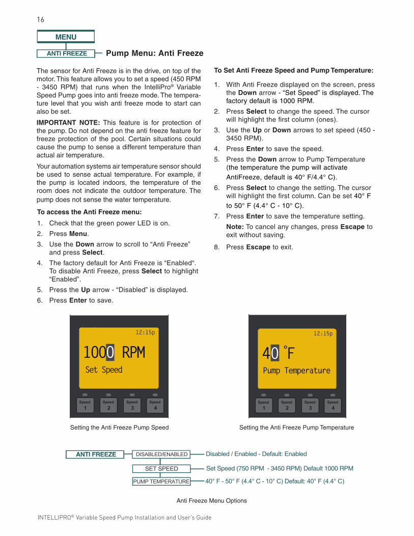
ThesensorforAntiFreezeisinthedrive,ontopofthemotor.Thisfeatureallowsyoutosetaspeed(450RPM- 3450 RPM) that runs when the IntelliPro® Variable Speed Pump goes into anti freeze mode. The tempera-ture level that you wish anti freeze mode to start can also be set.
IMPORTANT NOTE: This feature is for protection of thepump.Donotdependontheantifreezefeatureforfreeze protection of the pool. Certain situations could cause the pump to sense a different temperature than actual air temperature.
Your automation systems air temperature sensor should beused tosenseactual temperature.Forexample, ifthe pump is located indoors, the temperature of the room does not indicate the outdoor temperature. The pump does not sense the water temperature.
ANTI FREEZE Disabled / Enabled - Default: EnabledDISABLED/ENABLED
SET SPEED
40° F - 50° F (4.4° C - 10° C) Default: 40° F (4.4° C)PUMP TEMPERATURE
Set Speed (750 RPM - 3450 RPM) Default 1000 RPM
ANTI FREEZE Disabled / Enabled - Default: EnabledDISABLED/ENABLED
SET SPEED
40° F - 50° F (4.4° C - 10° C) Default: 40° F (4.4° C)PUMP TEMPERATURE
Set Speed (750 RPM - 3450 RPM) Default 1000 RPM
PRIMING DISABLED/ENABLED
(1 min. to 30 min. hrs.) Default: 11 minutesMAX PRIMING TIME
Disabled / Enabled - Default: Enabled
Default: Enabled
(1 - 100%) Default: 1PRIMED SENSITIVITY
(1 second - 10 minutes) Default: 20 secondsPRIMING DELAY
DISABLED/ENABLED
MENU
Pump Menu: Anti Freeze
12:15p
Pump Temperature
40 F°
To access the Anti Freeze menu:
1. CheckthatthegreenpowerLEDison.
2. PressMenu.
3. UsetheDownarrowtoscrollto“AntiFreeze”and press Select.
4. ThefactorydefaultforAntiFreezeis“Enabled“.TodisableAntiFreeze,pressSelect to highlight “Enabled”.
5. PresstheUparrow-“Disabled”isdisplayed.
6. PressEnter to save.
To Set Anti Freeze Speed and Pump Temperature:
1. WithAntiFreezedisplayedonthescreen,pressthe Down arrow - “Set Speed” is displayed. The factorydefaultis1000RPM.
2. PressSelect to change the speed. The cursor willhighlightthefirstcolumn(ones).
3. UsetheUp or Downarrowstosetspeed(450-3450RPM).
4. PressEnter to save the speed.
5. Press the Down arrow to Pump Temperature (the temperature the pump will activate AntiFreeze,defaultis40°F/4.4°C).
6. Press Select to change the setting. The cursor will highlight the first column. Can be set 40°Fto50°F(4.4°C-10°C).
7. Press Enter to save the temperature setting.
Note: To cancel any changes, press Escape to exit without saving.
8. PressEscape to exit.
SettingtheAntiFreezePumpTemperature
AntiFreezeMenuOptions
12:15p
Set Speed
1000 RPM
SettingtheAntiFreezePumpSpeed
17
INTELLIPRO® Variable Speed Pump Installation and User’s GuideINTELLIPRO® Variable Speed Pump Installation and User’s Guide
CONNECTING TO AN AUTOMATION SYSTEM
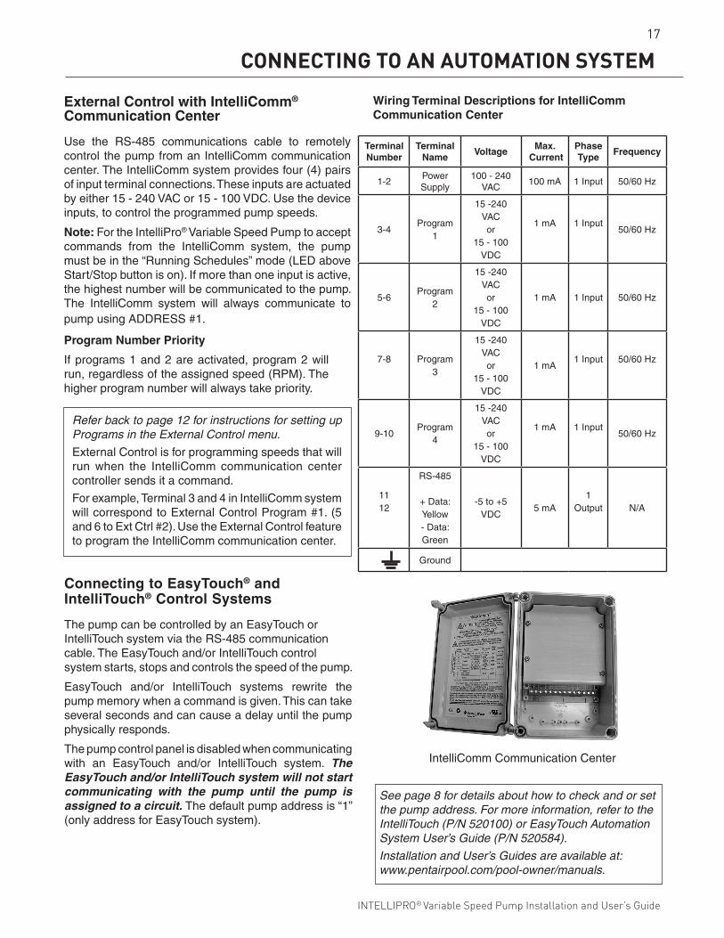
External Control with IntelliComm® Communication Center
Use the RS-485 communications cable to remotelycontrol the pump from an IntelliComm communication center.TheIntelliCommsystemprovidesfour(4)pairsof input terminal connections. These inputs are actuated byeither15-240VACor15-100VDC.Usethedeviceinputs, to control the programmed pump speeds.
Note:FortheIntelliPro® Variable Speed Pump to accept commands from the IntelliComm system, the pump mustbeinthe“RunningSchedules”mode(LEDaboveStart/Stopbuttonison).Ifmorethanoneinputisactive,the highest number will be communicated to the pump. The IntelliComm system will always communicate to pumpusingADDRESS#1.
Refer back to page 12 for instructions for setting up Programs in the External Control menu.
External Control is for programming speeds that will run when the IntelliComm communication center controller sends it a command.
Forexample,Terminal3and4inIntelliCommsystemwillcorrespondtoExternalControlProgram#1.(5and6toExtCtrl#2).UsetheExternalControlfeatureto program the IntelliComm communication center.
Terminal Number
Terminal Name
VoltageMax.
CurrentPhase Type
Frequency
1-2Power Supply
100-240VAC
100mA 1Input 50/60Hz
3-4Program
1
15-240VAC or
15-100VDC
1mA 1Input50/60Hz
5-6Program
2
15-240VAC or
15-100VDC
1mA 1Input 50/60Hz
7-8 Program 3
15-240VAC or
15-100VDC
1mA1Input 50/60Hz
9-10Program
4
15-240VAC or
15-100VDC
1mA 1Input50/60Hz
1112
RS-485
+Data:Yellow -Data:Green
-5to+5VDC
5mA1
Output N/A
Ground
IntelliComm Communication Center
Program Number Priority
Ifprograms1and2areactivated,program2willrun,regardlessoftheassignedspeed(RPM).Thehigherprogramnumberwillalwaystakepriority.
Connecting to EasyTouch® and IntelliTouch® Control Systems
The pump can be controlled by an EasyTouch orIntelliTouchsystemviatheRS-485communicationcable.TheEasyTouchand/orIntelliTouchcontrolsystem starts, stops and controls the speed of the pump.
EasyTouch and/or IntelliTouch systems rewrite thepumpmemorywhenacommandisgiven.Thiscantakeseveral seconds and can cause a delay until the pump physically responds.
The pump control panel is disabled when communicating with an EasyTouch and/or IntelliTouch system. The EasyTouch and/or IntelliTouch system will not start communicating with the pump until the pump is assigned to a circuit. Thedefaultpumpaddressis“1”(onlyaddressforEasyTouchsystem).
Wiring Terminal Descriptions for IntelliComm Communication Center
See page 8 for details about how to check and or set the pump address. For more information, refer to the IntelliTouch (P/N 520100) or EasyTouch Automation System User’s Guide (P/N 520584).
Installation and User’s Guides are available at: www.pentairpool.com/pool-owner/manuals.
INTELLIPRO® Variable Speed Pump Installation and User’s Guide
18
INTELLIPRO® Variable Speed Pump Installation and User’s Guide
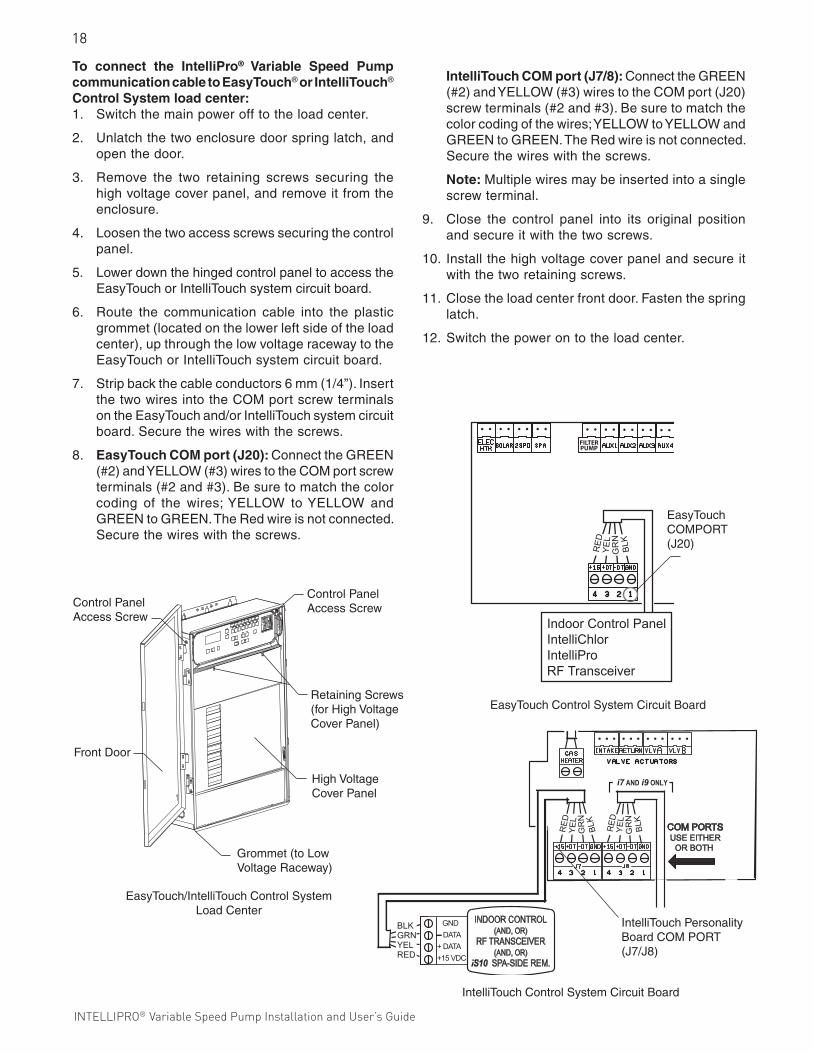
To connect the IntelliPro® Variable Speed Pump communication cable to EasyTouch® or IntelliTouch® Control System load center:1. Switchthemainpowerofftotheloadcenter.
2. Unlatchthetwoenclosuredoorspringlatch,andopen the door.
3. Remove the two retaining screws securing thehigh voltage cover panel, and remove it from the enclosure.
4. Loosenthetwoaccessscrewssecuringthecontrolpanel.
5. LowerdownthehingedcontrolpaneltoaccesstheEasyTouch or IntelliTouch system circuit board.
6. Route the communication cable into the plasticgrommet(locatedonthelowerleftsideoftheloadcenter),upthroughthelowvoltageracewaytotheEasyTouch or IntelliTouch system circuit board.
7. Stripbackthecableconductors6mm(1/4”).InsertthetwowiresintotheCOMportscrewterminalsontheEasyTouchand/orIntelliTouchsystemcircuitboard. Secure the wires with the screws.
8. EasyTouch COM port (J20): ConnecttheGREEN(#2)andYELLOW(#3)wirestotheCOMportscrewterminals(#2and#3).Besuretomatchthecolorcoding of the wires;YELLOW toYELLOW andGREENtoGREEN.TheRedwireisnotconnected.Secure the wires with the screws.
IntelliTouch COM port (J7/8): ConnecttheGREEN(#2)andYELLOW(#3)wirestotheCOMport(J20)screwterminals(#2and#3).Besuretomatchthecolorcodingofthewires;YELLOWtoYELLOWandGREENtoGREEN.TheRedwireisnotconnected.Secure the wires with the screws.
Note: Multiplewiresmaybeinsertedintoasinglescrew terminal.
9. Close the control panel into its original positionand secure it with the two screws.
10. Installthehighvoltagecoverpanelandsecureitwith the two retaining screws.
11. Closetheloadcenterfrontdoor.Fastenthespringlatch.
12. Switchthepowerontotheloadcenter.
EasyTouch/IntelliTouchControlSystemLoadCenter
Control Panel AccessScrew
HighVoltageCover Panel
RetainingScrews(forHighVoltageCoverPanel)
FrontDoor
Grommet(toLowVoltageRaceway)
Control Panel AccessScrew
EasyTouch Control System Circuit Board
Indoor Control PanelIntelliChlorIntelliProRF Transceiver
EasyTouch COMPORT(J20)
IntelliTouch Control System Circuit Board
BLKGRNYELRED
IntelliTouch Personality BoardCOMPORT (J7/J8)
19
INTELLIPRO® Variable Speed Pump Installation and User’s GuideINTELLIPRO® Variable Speed Pump Installation and User’s Guide
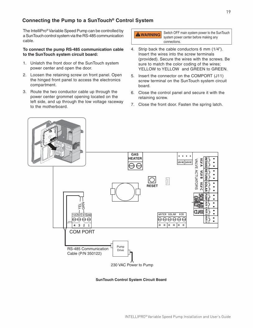
The IntelliPro® Variable Speed Pump can be controlled by aSunTouchcontrolsystemviatheRS-485communicationcable.
To connect the pump RS-485 communication cable to the SunTouch system circuit board:
1. UnlatchthefrontdooroftheSunTouchsystempower center and open the door.
2. Loosentheretainingscrewonfrontpanel.Openthe hinged front panel to access the electronics compartment.
3. Routethetwoconductorcableupthroughthepower center grommet opening located on the left side, and up through the low voltage raceway to the motherboard.
Connecting the Pump to a SunTouch® Control System
4. Stripbackthecableconductors6mm(1/4”).Insert the wires into the screw terminals (provided).Securethewireswiththescrews.Besuretomatchthecolorcodingofthewires; YELLOWtoYELLOWandGREENtoGREEN.
5. InserttheconnectorontheCOMPORT(J11)screw terminal on the SunTouch system circuit board.
6. Closethecontrolpanelandsecureitwiththeretaining screw.
7. Closethefrontdoor.Fastenthespringlatch.
SunTouch Control System Circuit Board
Switch OFF main system power to the SunTouch system power center before making any connections.
VA
LVE
AC
TU
ATOR
S
COM PORT
INTA
KE
RETU
RN
SOLA
R
AU
X 3
PUMP
AU
X 2A
UX
1
VLV
AV
LV B
VLV
C
ONLY
SOLAR
CLNR
GASHEATER
RESET
RS-485 CommunicationCable (P/N 350122)
PumpDrive
230 VAC Power to Pump
J11
INTELLIPRO® Variable Speed Pump Installation and User’s Guide
20
INTELLIPRO® Variable Speed Pump Installation and User’s Guide
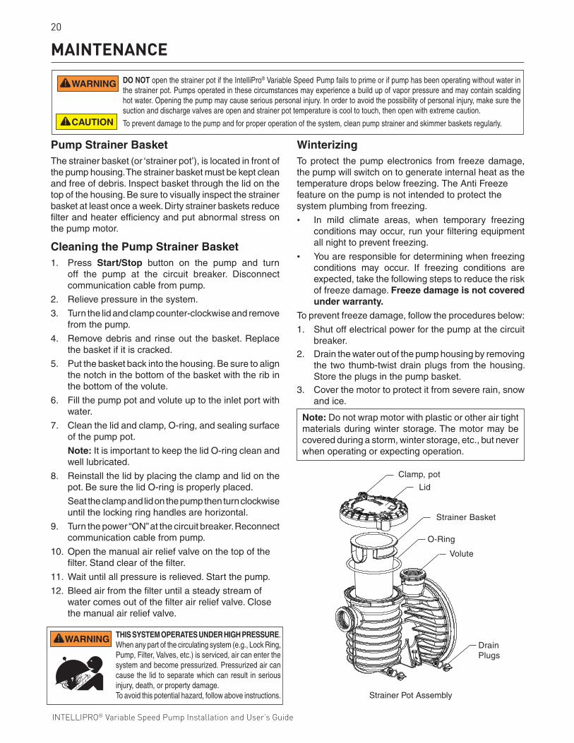
MAINTENANCE
Cleaning the Pump Strainer Basket1. Press Start/Stop button on the pump and turn
off the pump at the circuit breaker. Disconnectcommunication cable from pump.
2. Relievepressureinthesystem.
3. Turnthelidandclampcounter-clockwiseandremovefrom the pump.
4. Removedebrisandrinseout thebasket.Replacethebasketifitiscracked.
5. Putthebasketbackintothehousing. Be sure to align thenotchinthebottomofthebasketwiththeribinthe bottom of the volute.
6. Fillthepumppotandvoluteuptotheinletportwithwater.
7. Cleanthelidandclamp,O-ring,andsealingsurfaceof the pump pot.
Note:ItisimportanttokeepthelidO-ringcleanandwell lubricated.
8. Reinstallthelidbyplacingtheclampandlidonthepot.BesurethelidO-ringisproperlyplaced.
Seattheclampandlidonthepumpthenturnclockwiseuntilthelockingringhandlesarehorizontal.
9. Turnthepower“ON”atthecircuitbreaker.Reconnectcommunication cable from pump.
10. Openthemanualairreliefvalveonthetopofthefilter. Stand clear of the filter.
11. Waituntilallpressureisrelieved.Startthepump.
12. Bleedairfromthefilteruntilasteadystreamofwater comes out of the filter air relief valve. Close the manual air relief valve.
Pump Strainer BasketThestrainerbasket(or‘strainerpot’),islocatedinfrontofthepumphousing.Thestrainerbasketmustbekeptcleanandfreeofdebris.Inspectbasketthroughthelidonthetop of the housing. Be sure to visually inspect the strainer basketatleastonceaweek.Dirtystrainerbasketsreducefilter and heater efficiency and put abnormal stress on the pump motor.
DO NOT open the strainer pot if the IntelliPro® Variable Speed Pump fails to prime or if pump has been operating without water in the strainer pot. Pumps operated in these circumstances may experience a build up of vapor pressure and may contain scalding hot water. Opening the pump may cause serious personal injury. In order to avoid the possibility of personal injury, make sure the suction and discharge valves are open and strainer pot temperature is cool to touch, then open with extreme caution.
To prevent damage to the pump and for proper operation of the system, clean pump strainer and skimmer baskets regularly.
WinterizingTo protect the pump electronics from freeze damage, the pump will switch on to generate internal heat as the temperature drops below freezing. TheAntiFreezefeature on the pump is not intended to protect the system plumbing from freezing.
• In mild climate areas, when temporary freezing conditions may occur, run your filtering equipment all night to prevent freezing.
• You are responsible for determining when freezing conditions may occur. If freezing conditions are expected,takethefollowingstepstoreducetheriskof freeze damage. Freeze damage is not covered under warranty.
To prevent freeze damage, follow the procedures below:
1. Shutoffelectricalpowerforthepumpatthecircuitbreaker.
2. Drainthewateroutofthepumphousingbyremovingthe two thumb-twist drain plugs from the housing. Storetheplugsinthepumpbasket.
3. Coverthemotortoprotectitfromsevererain,snowand ice.
Note: Donotwrapmotorwithplasticorotherairtightmaterials during winter storage. The motor may be covered during a storm, winter storage, etc., but never when operating or expecting operation.
THIS SYSTEM OPERATES UNDER HIGH PRESSURE. When any part of the circulating system (e.g., Lock Ring, Pump, Filter, Valves, etc.) is serviced, air can enter the system and become pressurized. Pressurized air can cause the lid to separate which can result in serious injury, death, or property damage. To avoid this potential hazard, follow above instructions.
Clamp, pot
O-Ring
Lid
StrainerBasket
DrainPlugs
Volute
StrainerPotAssembly
21
INTELLIPRO® Variable Speed Pump Installation and User’s GuideINTELLIPRO® Variable Speed Pump Installation and User’s Guide
1. Releaseallpressurebyopeningallventsbeforestarting.Be sure gate valves and return piping are closed.
2. Drainthepumpbyremovingthedrainplugsonthebottomof the pump body and trap body.
3. Be sure there is no pressure in the trap body. Removethecover(unscrewbyturningthehandlering).
4. RemovetheclampholdingthepumphalvestogetherThemotor and seal plate assembly can now be pulled away from the pump body.
5. Removethefivescrewsandwashersholdingthediffusertothesealplate.Removethediffuser.
6. Holdtheimpellersecurelyinplacebyhand.Removetheimpellerlockscrewlocatedatthecenteroftheimpeller.Usingadeepwell3/4insocketwrenchwithracket,loosenthe left-handedscrewthread inaclockwisedirection.Removetheimpellerscrewo-ring.Inspecttheo-ringfordamage,cracks,etc.Replaceifdamaged.
7. Useaflatbladescrewdriver(3/16 intipwidth) toholdthe motor shaft. The motor shaft has a slot on the end which is accessible through the center of the fan. Note: Sometimes the impeller becomes tight on the shaft after years of service. It may be necessary to hold the screwdriver with a wrench or pliers as the torque may betoohightoholdbyhand.Forscrewdriversthathaveasquareshaftanadjustablewrenchmaybeusedtohelpholdthescrewdriver.Forscrewdriversthathavearoundshaftlockingpliersmaybeplacedonthehandleandusedto hold the screwdriver.
8. While holding the motor shaft, unscrew the impeller by hand fromthemotorshaft.Turntheimpellercounterclockwisewhen facing it to loosen. Note: If the impeller is too tight, use leather gloves to help loosen.
9. Pull the rotating member of the seal off the impeller sleeve. Clean the sleeve.
10. Removethefourscrewsholdingthesealplatetothemotor.
11. Place the seal plate face down on flat surface and tap out the ceramic seat.
12. Clean the seal cavity in the seal plate and clean the motor shaft.
Motor Care
Protect from heat
1. Shadethemotorfromthesun.2. Any enclosure must be well ventilated to prevent
overheating. 3. Provideamplecrossventilation.
Protect against dirt
1. Protectfromanyforeignmatter.2. Donotstore(orspill)chemicalsonornearthemotor.3. Avoidsweepingorstirringupdustnear themotor
while it is operating.4. Ifamotorhasbeendamagedbydirtitmayvoidthe
motor warranty.5. Cleanthelidandclamp,O-ring,andsealingsurface
of the pump pot.
Protect against moisture
1. Protect from continuous splashing or continuoussprayed water.
2. Protectfromextremeweathersuchasflooding.3. If motor internals have become wet - let it dry before
operating.Donotallowthepumptooperateifithasbeen flooded.
4. Ifamotorhasbeendamagedbywateritmayvoidthe motor warranty.
Shaft Seal Replacement
The Shaft Seal consists primarily of two parts, a rotating ceramic seal housed in the impeller and a stationary spring seal in the sealplate. The pump requires little or no service other than reasonable care, however, a shaft seal may occasionally become damaged and must be replaced.
Note: The polished and lapped faces of the seal could be damaged if not handled with care.
Pump Disassembly
RequiredTools:
• 1/2inopenendwrench(housingtofootbolts)• 1/4insocketwithratchetorwrench(diffuserscrews)
• 9/16inopenendwrench(motortosealplatebolts)• No.2Phillipsscrewdriver(drivetomotor)• 3/4indeepwellsocketwithratchet(impellerscrew)• Flatbladescrewdriver,3/16intipwidth(motorshaft)
SERVICINGAlways disconnect power to the IntelliPro® Variable Speed Pump at the circuit breaker and disconnect the communication cable before servicing the pump. Failure to do so could result in death or serious injury to service people, users or others due to electric shock. Read all servicing instructions before working on the pump.DO NOT open the strainer pot if pump fails to prime or if pump has been operating without water in the strainer pot. Pumps operated in these circumstances may experience a build up of vapor pressure and may contain scalding hot water. Opening the pump may cause serious personal injury. In order to avoid the possibility of personal injury, make sure the suction and discharge valves are open and strainer pot temperature is cool to touch, then open with extreme caution.Be sure not to scratch or mar the polished shaft seal faces; seal will leak if faces are damaged. The polished and lapped faces of the seal could be damaged if not handled with care.
Pump illustrated parts view on the next page

INTELLIPRO® Variable Speed Pump Installation and User’s Guide
22
INTELLIPRO® Variable Speed Pump Installation and User’s Guide
Drive Assembly Removal and Installation
To remove the drive assembly and control panel from the pump’s motor assembly:
1. DisconnecttheRS-485communicationcablefromthe pump.
2. Openthecontrolpanelcover.
3. RemovethethreePhillipsheadscrewssecuringthedrive to the motor assembly as shown.
4. Liftupthedriveassemblyandremoveit fromthemotor adapter located on top of the motor assembly.
To avoid electrical hazard, do not remove the four tamper proof screws from the motor assembly.
To avoid dangerous or fatal electrical shock hazard, switch OFF power to motor before working on pump or motor.
Continue onto next page
Pump Reassembly/Installing New Seal
1. Clean theceramicseatofdirt,grease,dust,etc.Wet the outer edge of the rubber cup on the ceramic seat with water. Press the ceramic seat into the seal plate firmly and squarely with finger pressure. See seal image below.
2. Placeceramicseatfaceuponbenchandrecleanthecavityifseatdoesnotlockproperly.
3. If the seat still does not lock properly, place acardboard washer over the polished face and use apieceof3/4”(19mm)standardpipeforpressingpurposes.
4. Remountsealplateonthemotor.Tightentheboltsto60-80inch-lbs.(69-92kg/cm)torque.
5. Apply a small amount of liquid detergent to theinside diameter of rotating half of seal.
6. Slidetherotatingsealmember,polishedfacelast,over impeller sleeve until the rubber drive ring contacts the shoulder. Note: Besurenottonickorscratchthepolishedsealface.Thesealwillleakifthe face is damaged.
7. Screwtheimpellerontotheshaft(clockwise);thiswill automatically lock the seal in the seal plate.Note: Onmodelswithanimpellerscrew:Installtheimpellergasketandlockscrew(left-handthread-turncounter-clockwise).Torquelockscrewto50-55inch-lbs.(57.6-63kg/cm).
8. Mountthediffuseronthesealplate.Tightenscrewsto10-14inch-lbs.(11.2-16.1kg/cm)torque.
9. Assemblethemotorandsealplate to thevolute.Be sure the clamp is properly seated
Note: Clampknobcanbelocatedinanypositionaroundvolute;ifitismovedafterassembly,tightenknobwhiletappingaroundclamptoassistsealing.Donotmoveclampwhilepumpisfullofwater.
10. ReconnecttheRS-485communicationcabletothepump.
11. Fillthepumpwithwater.
12. Reinstallthepumplidandplasticclamp.See“PumpStrainerBasket”onpage20fordetails.
13. Primethepump.See“PrimingthePump,”onpage4formoreinformation.
Illustrated Parts View
Seal Plate
O-Ring
Diffuser
Impeller Screw
MotorBolts(4x)
Impeller(notshown)
O-Ring
Press Seal into plate firmly
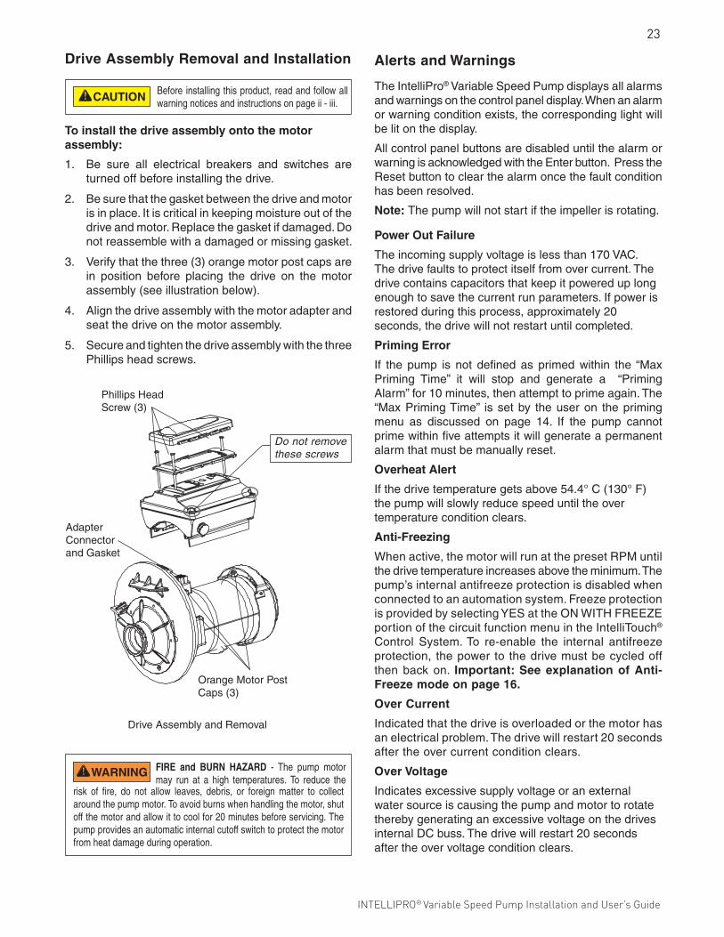
23
INTELLIPRO® Variable Speed Pump Installation and User’s GuideINTELLIPRO® Variable Speed Pump Installation and User’s Guide
Alerts and Warnings
The IntelliPro® Variable Speed Pump displays all alarms and warnings on the control panel display. When an alarm or warning condition exists, the corresponding light will be lit on the display.
AllcontrolpanelbuttonsaredisableduntilthealarmorwarningisacknowledgedwiththeEnterbutton.PresstheResetbuttontoclearthealarmoncethefaultconditionhas been resolved.
Note: The pump will not start if the impeller is rotating.
Power Out Failure
Theincomingsupplyvoltageislessthan170VAC.The drive faults to protect itself from over current. The drivecontainscapacitorsthatkeepitpowereduplongenough to save the current run parameters. If power is restoredduringthisprocess,approximately20seconds, the drive will not restart until completed.
Priming Error
If the pump is not defined as primed within the “MaxPriming Time” it will stop and generate a “Priming Alarm”for10minutes,thenattempttoprimeagain.The“MaxPrimingTime” issetby theuseron theprimingmenu as discussed on page 14. If the pump cannotprime within five attempts it will generate a permanent alarm that must be manually reset.
Overheat Alert
Ifthedrivetemperaturegetsabove54.4°C(130°F)the pump will slowly reduce speed until the over temperature condition clears.
Anti-Freezing
Whenactive,themotorwillrunatthepresetRPMuntilthe drive temperature increases above the minimum. The pump’s internal antifreeze protection is disabled when connectedtoanautomationsystem.FreezeprotectionisprovidedbyselectingYESattheONWITHFREEZEportion of the circuit function menu in the IntelliTouch® Control System. To re-enable the internal antifreeze protection, the power to the drive must be cycled off thenbackon. Important: See explanation of Anti-Freeze mode on page 16.
Over Current
Indicated that the drive is overloaded or the motor has anelectricalproblem.Thedrivewillrestart20secondsafter the over current condition clears.
Over Voltage
Indicates excessive supply voltage or an external water source is causing the pump and motor to rotate thereby generating an excessive voltage on the drives internalDCbuss.Thedrivewillrestart20secondsafter the over voltage condition clears.
Drive Assembly Removal and Installation
To install the drive assembly onto the motor assembly:
1. Be sure all electrical breakers and switches areturned off before installing the drive.
2. Besurethatthegasketbetweenthedriveandmotorisinplace.Itiscriticalinkeepingmoistureoutofthedriveandmotor.Replacethegasketifdamaged.Donotreassemblewithadamagedormissinggasket.
3. Verifythatthethree(3)orangemotorpostcapsarein position before placing the drive on the motor assembly(seeillustrationbelow).
4. Alignthedriveassemblywiththemotoradapterandseat the drive on the motor assembly.
5. SecureandtightenthedriveassemblywiththethreePhillips head screws.
DriveAssemblyandRemoval
Illustrated Parts View
FIRE and BURN HAZARD - The pump motor may run at a high temperatures. To reduce the
risk of fire, do not allow leaves, debris, or foreign matter to collect around the pump motor. To avoid burns when handling the motor, shut off the motor and allow it to cool for 20 minutes before servicing. The pump provides an automatic internal cutoff switch to protect the motor from heat damage during operation.
Before installing this product, read and follow all warning notices and instructions on page ii - iii.
Do not remove these screws
PhillipsHeadScrew(3)
AdapterConnectorandGasket
OrangeMotorPostCaps(3)
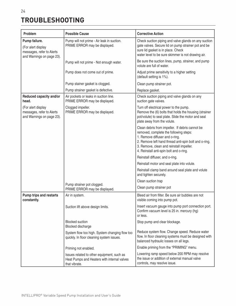
INTELLIPRO® Variable Speed Pump Installation and User’s Guide
24
INTELLIPRO® Variable Speed Pump Installation and User’s Guide
TROUBLESHOOTING
Problem Possible Cause Corrective Action
Pump failure.
(For alert display messages, refer to Alerts and Warnings on page 23).
Pump will not prime - Air leak in suction.PRIME ERROR may be displayed.
Pump will not prime - Not enough water.
Pump does not come out of prime.
Pump stainer gasket is clogged.
Pump strainer gasket is defective.
Check suction piping and valve glands on any suction gate valves. Secure lid on pump strainer pot and be sure lid gasket is in place. Check water level to be sure skimmer is not drawing air.
Be sure the suction lines, pump, strainer, and pump volute are full of water.
Adjust prime sensitivity to a higher setting (default setting is 1%).
Clean pump strainer pot.
Replace gasket.
Reduced capacity and/or head.
(For alert display messages, refer to Alerts and Warnings on page 23).
Air pockets or leaks in suction line.PRIME ERROR may be displayed.
Clogged impeller.PRIME ERROR may be displayed.
Pump strainer pot clogged.PRIME ERROR may be displayed.
Check suction piping and valve glands on any suction gate valves.
Turn off electrical power to the pump.Remove the (6) bolts that holds the housing (strainer pot/volute) to seal plate. Slide the motor and seal plate away from the volute.
Clean debris from impeller. If debris cannot be removed, complete the following steps:1. Remove diffuser and o-ring.2. Remove left hand thread anti-spin bolt and o-ring.3. Remove, clean and reinstall impeller.4. Reinstall anti-spin bolt and o-ring.
Reinstall diffuser, and o-ring.
Reinstall motor and seal plate into volute.
Reinstall clamp band around seal plate and volute and tighten securely.
Clean suction trap
Clean pump strainer pot
Pump trips and restartsconstantly.
Air in system.
Suction lift above design limits.
Blocked suctionBlocked discharge
System flow too high. System changing flow too quickly. In floor cleaning system issues.
Priming not enabled.
Issues related to other equipment, such as Heat Pumps and Heaters with internal valves that vibrate.
Bleed air from filter. Be sure air bubbles are not visible coming into pump pot.
Insert vacuum gauge into pump port connection port. Confirm vacuum level is 25 in. mercury (hg) or less.
Stop pump and clear blockage.
Reduce system flow. Change speed. Reduce water flow. In floor cleaning systems must be designed with balanced hydraulic losses on all legs.
Enable priming from the “PRIMING” menu.
Lowering ramp speed below 200 RPM may resolve the issue or addition of external manual valve controls, may resolve issue.
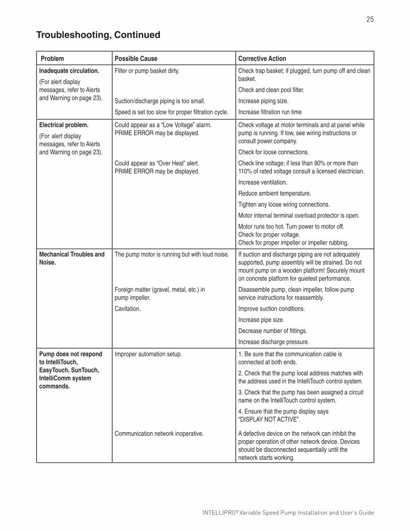
25
INTELLIPRO® Variable Speed Pump Installation and User’s GuideINTELLIPRO® Variable Speed Pump Installation and User’s Guide
Problem Possible Cause Corrective Action
Inadequate circulation.
(For alert displaymessages, refer to Alertsand Warning on page 23).
Filter or pump basket dirty.
Suction/discharge piping is too small.
Speed is set too slow for proper filtration cycle.
Check trap basket; if plugged, turn pump off and clean basket.
Check and clean pool filter.
Increase piping size.
Increase filtration run time
Electrical problem.
(For alert displaymessages, refer to Alertsand Warning on page 23).
Could appear as a “Low Voltage” alarm.PRIME ERROR may be displayed.
Could appear as “Over Heat” alert.PRIME ERROR may be displayed.
Check voltage at motor terminals and at panel while pump is running. If low, see wiring instructions or consult power company.
Check for loose connections.
Check line voltage; if less than 90% or more than 110% of rated voltage consult a licensed electrician.
Increase ventilation.
Reduce ambient temperature.
Tighten any loose wiring connections.
Motor internal terminal overload protector is open.
Motor runs too hot. Turn power to motor off.Check for proper voltage.Check for proper impeller or impeller rubbing.
Mechanical Troubles and Noise.
The pump motor is running but with loud noise.
Foreign matter (gravel, metal, etc.) in pump impeller.
Cavitation.
If suction and discharge piping are not adequately supported, pump assembly will be strained. Do notmount pump on a wooden platform! Securely mount on concrete platform for quietest performance.
Disassemble pump, clean impeller, follow pump service instructions for reassembly.
Improve suction conditions.
Increase pipe size.
Decrease number of fittings.
Increase discharge pressure.
Pump does not respondto IntelliTouch, EasyTouch, SunTouch, IntelliComm system commands.
Improper automation setup.
Communication network inoperative.
1. Be sure that the communication cable is connected at both ends.
2. Check that the pump local address matches with the address used in the IntelliTouch control system.
3. Check that the pump has been assigned a circuit name on the IntelliTouch control system.
4. Ensure that the pump display says “DISPLAY NOT ACTIVE”.
A defective device on the network can inhibit the proper operation of other network device. Devicesshould be disconnected sequentially until the network starts working.
Troubleshooting, Continued
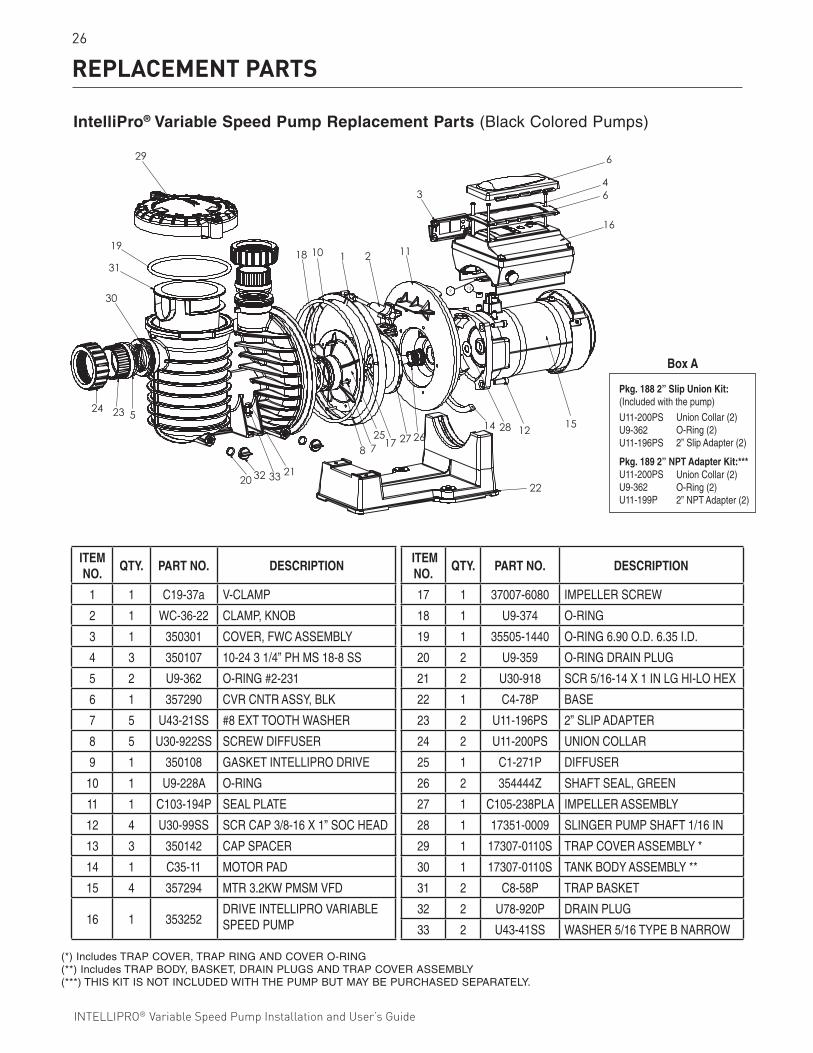
INTELLIPRO® Variable Speed Pump Installation and User’s Guide
26
INTELLIPRO® Variable Speed Pump Installation and User’s Guide
REPLACEMENT PARTS
913
8 725
17 27 26
20 32 33 21
24 23 5
19
31
30
29
18 10 1 2 11
3
6
46
16
15122814
22
Box A
Pkg. 188 2” Slip Union Kit: (Included with the pump)
U11-200PSU9-362U11-196PS
Pkg. 189 2” NPT Adapter Kit:***U11-200PSU9-362U11-199P
Union Collar (2)O-Ring (2)2” Slip Adapter (2)
Union Collar (2)O-Ring (2)2” NPT Adapter (2)
IntelliPro® Variable Speed Pump Replacement Parts(BlackColoredPumps)
(*)IncludesTRAPCOVER,TRAPRINGANDCOVERO-RING(**)IncludesTRAPBODY,BASKET,DRAINPLUGSANDTRAPCOVERASSEMBLY(***)THISKITISNOTINCLUDEDWITHTHEPUMPBUTMAYBEPURCHASEDSEPARATELY.
ITEM NO.
QTY. PART NO. DESCRIPTION
1 1 C19-37a V-CLAMP
2 1 WC-36-22 CLAMP, KNOB
3 1 350301 COVER, FWC ASSEMBLY
4 3 350107 10-24 3 1/4” PH MS 18-8 SS
5 2 U9-362 O-RING #2-231
6 1 357290 CVR CNTR ASSY, BLK
7 5 U43-21SS #8 EXT TOOTH WASHER
8 5 U30-922SS SCREW DIFFUSER
9 1 350108 GASKET INTELLIPRO DRIVE
10 1 U9-228A O-RING
11 1 C103-194P SEAL PLATE
12 4 U30-99SS SCR CAP 3/8-16 X 1” SOC HEAD
13 3 350142 CAP SPACER
14 1 C35-11 MOTOR PAD
15 4 357294 MTR 3.2KW PMSM VFD
16 1 353252DRIVE INTELLIPRO VARIABLE SPEED PUMP
ITEM NO.
QTY. PART NO. DESCRIPTION
17 1 37007-6080 IMPELLER SCREW
18 1 U9-374 O-RING
19 1 35505-1440 O-RING 6.90 O.D. 6.35 I.D.
20 2 U9-359 O-RING DRAIN PLUG
21 2 U30-918 SCR 5/16-14 X 1 IN LG HI-LO HEX
22 1 C4-78P BASE
23 2 U11-196PS 2” SLIP ADAPTER
24 2 U11-200PS UNION COLLAR
25 1 C1-271P DIFFUSER
26 2 354444Z SHAFT SEAL, GREEN
27 1 C105-238PLA IMPELLER ASSEMBLY
28 1 17351-0009 SLINGER PUMP SHAFT 1/16 IN
29 1 17307-0110S TRAP COVER ASSEMBLY *
30 1 17307-0110S TANK BODY ASSEMBLY **
31 2 C8-58P TRAP BASKET
32 2 U78-920P DRAIN PLUG
33 2 U43-41SS WASHER 5/16 TYPE B NARROW
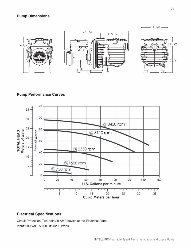
27
INTELLIPRO® Variable Speed Pump Installation and User’s GuideINTELLIPRO® Variable Speed Pump Installation and User’s Guide
3110 rpm
2350 rpm
3450 rpm
750 rpm1500 rpm
U.S. Gallons per minute
Cubic Meters per hour
Fee
t o
f w
ater
TOTA
L H
EA
DM
eter
s o
f w
ater
Pump Performance Curves
Pump Dimensions
Electrical Specifications
CircuitProtection:Two-pole20AMPdeviceattheElectricalPanel.
Input:230VAC,50/60Hz,3200Watts
14 1/2
10 3/4
11 1/8
14 1/2
26 1/411 7/16
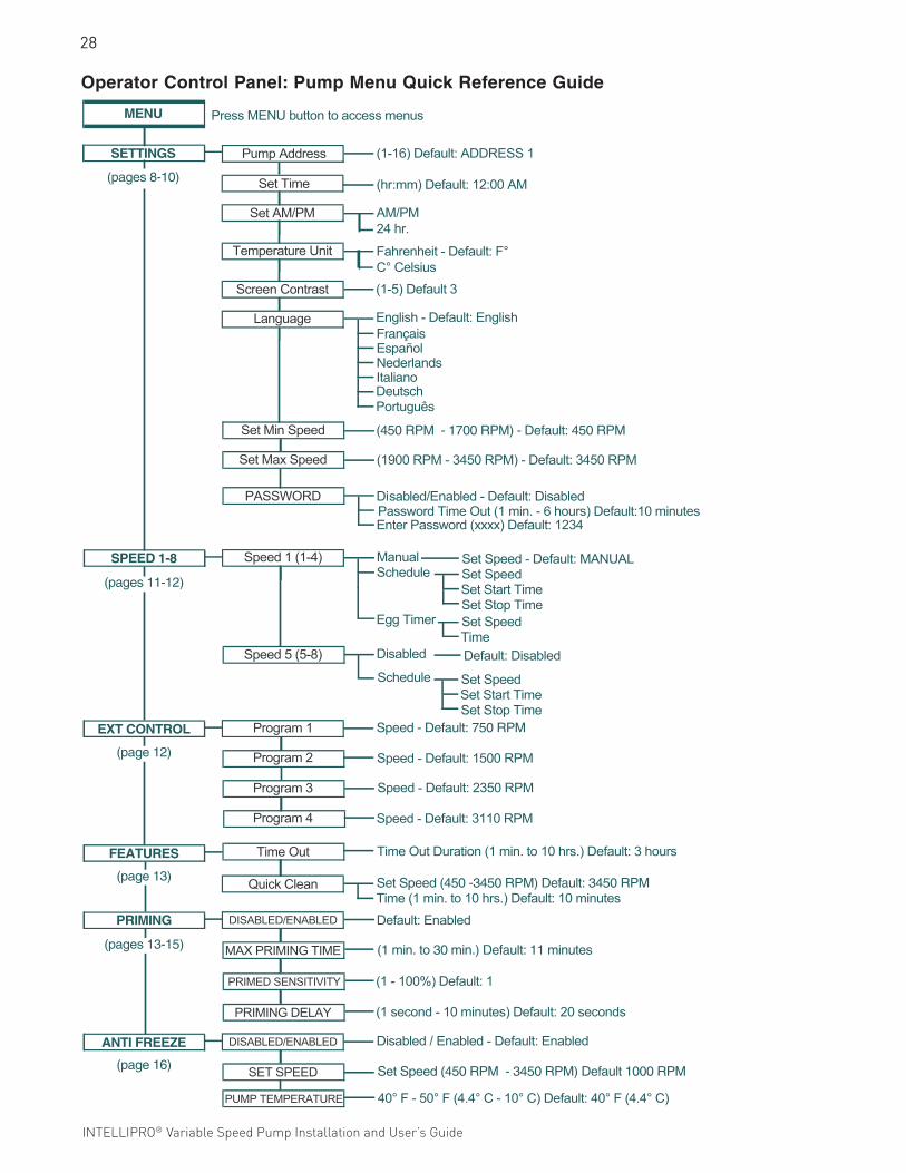
28
INTELLIPRO® Variable Speed Pump Installation and User’s Guide
Operator Control Panel: Pump Menu Quick Reference Guide
Press MENU button to access menus
(1-16) Default: ADDRESS 1
(hr:mm) Default: 12:00 AM
AM/PM24 hr.
Fahrenheit - Default: F°C° Celsius(1-5) Default 3
(450 RPM - 1700 RPM) - Default: 450 RPM
(1900 RPM - 3450 RPM) - Default: 3450 RPM
Password Time Out (1 min. - 6 hours) Default:10 minutes Disabled/Enabled - Default: Disabled
Enter Password (xxxx) Default: 1234
Manual Schedule
Egg Timer
Set Speed - Default: MANUAL Set Speed Set Start Time Set Stop Time Set Speed Time
Speed - Default: 750 RPM
Speed - Default: 1500 RPM
Set Speed (450 -3450 RPM) Default: 3450 RPM Time (1 min. to 10 hrs.) Default: 10 minutes
Time Out Duration (1 min. to 10 hrs.) Default: 3 hours
(1 min. to 30 min.) Default: 11 minutes
Disabled / Enabled - Default: Enabled
Speed - Default: 2350 RPM
Speed - Default: 3110 RPM
English - Default: English
Schedule Set Speed Set Start Time Set Stop Time
Disabled Default: Disabled
Default: Enabled
(1 - 100%) Default: 1
(1 second - 10 minutes) Default: 20 seconds
40° F - 50° F (4.4° C - 10° C) Default: 40° F (4.4° C)
Set Speed (450 RPM - 3450 RPM) Default 1000 RPM
SETTINGS
MENU
SPEED 1-8
EXT CONTROL
FEATURES
PRIMING
ANTI FREEZE
FrançaisEspañolNederlandsItaliano
PortuguêsDeutsch
Set AM/PM
Pump Address
Set Time
Temperature Unit
Screen Contrast
Language
Set Min Speed
Set Max Speed
PASSWORD
Speed 1 (1-4)
Program 1
Program 2
Quick Clean
Time Out
DISABLED/ENABLED
MAX PRIMING TIME
Program 3
Program 4
Speed 5 (5-8)
PRIMED SENSITIVITY
PRIMING DELAY
DISABLED/ENABLED
SET SPEED
PUMP TEMPERATURE
(pages 8-10)
(pages 11-12)
(page 12)
(page 13)
(pages 13-15)
(page 16)

NOTES

SPARUS™ 160 Energy Efficient Aquaculture Duty Pump Installation and User’s Guide
NOTES

NOTES

INTELLIPRO® Variable Speed Pump Installation and User’s Guide
1620 HAWKINS AVE., SANFORD, NC 27330 • (919) 566-800010951 WEST LOS ANGELES AVE., MOORPARK, CA 93021 • (805) 553-5000 WWW.PENTAIRPOOL.COMAll Pentair trademarks and logos are owned by Pentair, Inc. Pentair Aquatic Systems™, Sta-Rite®, IntelliPro®, IntelliComm®, EasyTouch®, IntelliTouch®, SunTouch® and Eco Select® are trademarks and/or registered trademarks of Pentair Water Pool and Spa, Inc. and/or its affiliated companies in the United States and/ or other countries. Unless expressly noted, names and brands of third parties that may be used in this document are not used to indicate an affiliation or endorsement between the owners of these names and brands and Pentair Water Pool and Spa, Inc. Those names and brands may be the trademarks or registered trademarks of those third parties. Because we are continuously improving our products and services, Pentair reserves the right to change specifications without prior notice. Pentair is an equal opportunity employer.© 2013 Pentair Water Pool and Spa, Inc. All rights reserved. This document is subject to change without notice.
P/N 354831 REV. B 12/2/13*354831*
*354832*LIT. PKG. P/N 354832