Embed Size (px)
Citation preview

Intelligent Parametric Visual Thinking System (IPVTS) as a Paradigm
for Control Strategies with Time-Delay in Robotics
Review of the NRC project performed by N. Tikhonov in Air Force Research Lab, Wright –
Patterson
STATEMENT OF THE PROBLEM
The objective of this research is to develop better theoretical and practical methods for
using virtual reality, image understanding technologies, and conceptual parametric object-
oriented design for control strategies in Robotics, algorithms and software that is based on
coordinating and adapting the appropriate virtual reality visual display with the appropriate
sensory feedback (force, tactile) for modeling high-level descriptions of the sensing of
surfaces, shapes, and textures.
The Human Sensory Feedback (HSF) project at the AFRL headed by Dr. Repperger
[Repperger et al., 1995, 1997, 2000 ], captures attention of computer scientists and engineers as
a new methodology for building human-robot technology and for the support for many aspects
of requirements analysis that simulates an expert in the performance of control tasks.
However the problems of control in Robotics based on human-like control behavior, with
the appropriate sensory feedback for a integrated real-time system, are complex and many-sided.
During this transformation process the HSF provides automated support for many aspects of
virtual reality interfaces using Visual and Haptic rendering based on maintaining consistency
between graphical views and algebraic notation of a design [Repperger et al., 1995, 1997, 2000 ].
Thus engineering methods and procedures that encompass both geometric and non-
geometric objects require a level of human-like intelligence for understanding this paradigm,
which current methods do not support. Most of the existing systems can execute direct human
instructions yet cannot help him in abstract thinking. Considering this analysis, the research
objectives of this proposal are:
To develop theoretical and practical methods of coordinating and adapting the
appropriate virtual reality visual display with the appropriate sensory feedback (force,

tactile) in a simulation for robotics using image understanding technologies based on
new technology - Intelligent Parametric Visual Thinking System (IPVTS).
To transform a visual spatial model into a control process algorithm to achieve the
required functional properties with optimal characteristics.
It is necessary to create the IPVTS that has an intelligent human-like engineering
methodology where design, geometry, analysis, intelligent control and optimization are
combined into a single computational system to aid in engineering design using high-level
visual prototyping.
BACKGROUND AND RELEVANCE TO PREVIOUS WORK
The need for investigations of alternative sensory feedback, such as with a Haptic interface,
is indicated by being extremely important for adaptive remote control of complex integrated
systems. This is because the human hand is a powerful tool through which the human brain
interacts with the world [Repperger 1997], [Flanagan 2002]. According to publications
[Repperger et al., 1995, 1997, 2000] and other scientists [Flanagan 2002], it is necessary to note
that fundamental research in development methods of Haptic interfaces and “virtual force”
methodology have significant importance in improving the operator’s ability to observe and
control his environment.
The paper [Repperger 1995] addresses adapting the kinematical control for robots and
concludes with a review and description of prior work with problems involving dynamics,
control, design , the trajectory and speed planning utilizing control, and data flow based on
the mathematical model using Denevit-Hartenberg transformation [Repperger 1995]. This
paper shows how the seventeen coordinate systems based on Denevit - Hartenberg
transformation are used for the formal model of the components orientation. To improve these
developments we define the focus for this proposal on intelligent human-robot interface models
for generating the global formal graphical universal model based on sensory perception and
visual thinking.

In the work [Repperger 1997], it describes how a haptic interface was correlated to the visual
scene displayed to the pilots.
Early research in this area has demonstrated certain benefits of using Virtual Reality
Systems. In the reference [Floyd 1999], this author has developed the system in which the
PHANToM can interact with the 3D bitmapped virtual environments using the Cellular
Automata CAM-8 Modeling. Methods for control in Robotics based on the time delay and the
wave variables are described, also, to design the system with high effectiveness. This
bitmapped simulation allows the extracted position data and return force data directly with
the PHANToM robotic simulation. It allows the user to create a very universal method of
modeling. This is main advantage of this system, but this system has low speed for complex
systems and requires a very large computational resource. It should be noted that this system has
a lower number of control parameters for the objects involving optimization.
However, it is more important to integrate the bitmapped environment and the discrete
dynamical system with a high-level computational system based on a graphic implementation
and a combination of heuristics [Tikhonov 2002].
Extending on these works we believe that there is a need for a fundamental work to
automatically generate suitable control strategies for robots and position tracking
involving complex shape surfaces and textures, such a model has a feature-based visual model
in the query using formal graphic specifications and visual thinking.
To improve these developments we define the focus on this proposal based on intelligent
human-robot interface models for generating the global formal graphical universal model based
on sensory perception and the visual thinking.
Creating of integration mechanisms for IPVTS which will provide the integration including
multi-sensory feedback tools, using mathematical modeling and programming languages ( C++,
Java, Visual Basic.), and other integration formats and databases.

GENERAL METHODOLOGY AND PROCEDURES
Extending the robotics model [ Repperger 1995], it is required to develop a new discrete
dynamical system ( Fig. 1) as high-level computational systems with graphic implementation
and a combination of heuristics:
G = [ V, E, T (V), C (V), X i (V), Yi (V), Zi (V),, Ai (V), H Fi (V), Pi (V), P Fi (V), B Di (V),
TOi (V), Wi (V) ,P Bi (V), Gi (V) , SBi (V)] (1)
where a composite node’s implementation is the graph G, V is the set of vertices of regular
lattice associated with edges E, minimum execution time T(V) and control constraints C(V)
associated with V, X i (V), Y i (V), Zi(V) are coordinates of vertices of vectors associated with
V; homogeneous transformation matrix A i (V), heuristic functions and rules HF i (V),
parametric constraints P i (V), parametric function PF i (V), feedback function (as bias distance)
BD i (V), text TO i (V); connection weighs, W i (V), local feedback function PB i (V), genetic
code G i (V), and optimization criterion SB i (V) . For example, the relative position and
orientation of frame (XYZ)i with respect to frame (XYZ)i-1
(Fig. 1), can now be expressed by
a homogeneous transformation matrix A i (V) and complex composition matrix A (V)01 (for
representation of the vector 01) which describes the composition of the translation matrix
T01, the translation inverse matrix T01-1
, the rotation matrices, )(R X01 , )(R Y01 , RY01,
RZ01, )(R Z01 on angles respect to coordinate axes Xi
, Yi, Zi
[ Foley , 1996 ] , the
inverse rotation matrices RZ01-1, RY01-1
and scaling transformation matrix S01 for
arbitrary vector 01 as follows:
A i (V) = A (V)01= T01-1
* RZ01-1* RY01-1
*S01* )(R X01 * )(R Y01
* )(R Z01 *
RY01* RZ01
* T01 (2)
The structure of IPVTS is a tree consisting of atomic and composite nodes (Fig. 1, Fig 2).
The IPVTS automatically allows the transform of each formal parameter from graphic
specification CAD systems into a primitive vector-prototype of fractal homogeneous neural

network in according with the homogeneous composition the vector transformation matrix
A V)m( based on generated hypergraph model matrix
A V)m( = A01 A12 A23…………………………. A(m-1)m (3)
The general concept and procedure of IPVTS (Fig. 1, Fig. 2) consists of the followings steps:
create the intelligent objects with visual information using mechanisms of homogeneous
fractal interpreting visual images (Fig. 1, Fig. 2) . This method is based on self-similarity of
atomic and composite prototypes and consists in modeling of composite prototypes by several
smaller fragments of themselves. The image is sliced in segments of irregular or regular form
using the minimum execution time T(V) of prototypes (Fig. 1). During this concept, our
approach allows structuring the homogeneous composition transformation matrix (2) A i (V) and
hypergraph model matrix A V)m( (3) into components which can be executed in parallel as
separate standard parametric prototypes (For example, the matrices A01, A12
, etc.).
Fig. 1 Functional schema of control strategies for robotics using IPVTS

generate a homogeneous network of nodes, each of which can be of a finite number of V
possible states updates in discrete time steps according to the IPVTS model (1) with
local identical interaction rule (see Fig. 1, 2);
build initial 3D or m-vector parametric model based on Geometric Modeling System
(Fig. 2) and model (1) with parametric function PF i (V) and parametric constraints
P i (V) (for example the force) using both the IPVTS graphic specification and the full
automatic transformation from geometric model or CAD systems;
create the intelligent objects with visual information using mechanisms of homogeneous
fractal interpreting visual images (Fig. 1, Fig. 2) . This method is based on self-similarity of
atomic and composite prototypes and consists in modeling of composite prototype by several
smaller fragments of themselves. The image is sliced into segments of irregular or regular
form using the minimum execution time T(V) of prototypes (Fig. 1). During this concept,
our approach allows structuring the homogeneous composition transformation matrix (2)
A i (V) and hypergraph model matrix A V)m( (3) into components which can be executed
parallel as separate standard parametric prototypes (For example, the matrices A01, A12
,
etc.).
generate a homogeneous network of nodes, each of which can be of a finite number of V
possible states updates in discrete time steps according to IPVTS model (1) with local
identical interaction rule (see Fig. 1, 2);
build initial 3D or m-vector parametric model based on Geometric Modeling System (Fig. 2)
and model (1) with parametric function PF i (V) and parametric constraints P i (V) (for
example the force) using both the IPVTS graphic specification and the fully automatic
transformation from the geometric model or CAD systems;
update a site of nodes of a homogeneous lattice according to a definite heuristic rule and
heuristic functions HF i (V) that involve a neighborhood of sites around each one. Global
control heuristic for all nodes of a model is a feedback function (bias distance) BD i (V) for

transform of the parametric constraints P i (V) such as dimensions and normal/shear forces
(Fig.1).
Fig. 2 The human-machine haptic interface based on IPVTS algorithm
change the sites of nodes of a homogeneous lattice according to control constraints C(V), the
parametric constraints P i (V), a definite heuristic rules and heuristic functions PF i (V)
involving the values of its nearest neighbors, where the position of sites around each of the
vertices are determined relative to a local system of coordinates. It is implemented as a set of
situation-action rules associated with Generalized Design Logic, and Knowledge Database
(Fig.2) that implements the local solving method based on triangular systems of neighborhood
structures;
transform of the parametric constraints P i (V) or C(V). IPVTS uses the global control
heuristic for all nodes of the model such as a bias distance (feedback) BD i (V) associated
with local system of coordinates from node to node along the edges (Fig.1);
determine and evaluate the several possible parameters of lattices of the neighborhood
structures for this step with respect to global structures for this step and global system of

coordinates using both the homogeneous transformation matrix Ai (V) and heuristic functions
HF i (V) with learning parametric function of geometric objects (Fig.2);
convert atomic prototypes into many-level concept's system developing the "intelligent"
parameterized prototype-classes and prototype-objects using on object-oriented analysis and
composition of system from hierarchical modules based on SQL database and knowledge database
(Fig. 2.);
make the automatic constraints check with dimensional chains and relationships to the
composite prototype;
repeat all consecutive or concurrent steps for all vertices of a network with computing
connection weighs W i (V), cost weighs SB i (V), and genetic code (chromosome) G i (V) for
search of optimal solutions.
EXPLANATION OF NEW AND UNUSUAL TECHNIQUES
A major difference between the IPVTS methodology and other systems is that it
automatically specifies the method requiring parametric automatically coding for a genetic
structure of the model, of the sensors and working components that have two styles for rapid
prototyping:
analytically using algebraic notation and formal specification;
visual with formal parametric geometric representations.
IPVTS allows us to develop a wide variety of learning genetic algorithms created from
graphical specifications. This approach has the following advantages over current practice:
IPVTS is a simple system for very complex behaviors because they have used general
and simple rules with heuristic functions HF i (V). It allows easily and quickly derived
simulations to visualize a m-dimensional space with an n-vector attached to each point
in the space in according to physical phenomena.

It allows the development of a graphical formal specification that is fully associated
with the task of learning the parameters, weights and structure of each of these
representations for genetic optimization.
We can sense both normal and shear forces as well as render texture using the
PHANTOM robotic systems. We can also generate texture on a joystick and use
a number of force reflecting robotic devices to test this theory and practical
application of the methodology.
EXPECTED RESULTS AND THEIR SIGNIFICANCE AND APPLICATION.
IPVTS is a simple system that exhibits very complicated behavior using global control
strategies, generic rule and heuristics. IPVTS will allow the implementation of the following:
Image understanding and converting into high-level robotics/ human-machine
interface models, which allow us to remove the operators from potential hazardous
environments;
Automatic generating target trajectory, surface shapes and texture and also other
control programs from graphic specification using IPVTS;
Simulating, visualizing and checking constraints of integrated systems such as
forces and pressure using the knowledge database more accurately and usually faster
than conventional algorithms;
Dramatically improving both the quality and speed of control tasks for a system of
linear, polynomial or transcendental equations instead of the Newton-Raphson
method.
Run Haptic Research based on the reflected force for PHANToM devices with
time delay and employing wave variables to improve situational awareness and
operator performance.

The dynamic intelligent parameterization is used, in this system, to provide a great
opportunity to transform a visual spatial model into a control process algorithm to
achieving the required functional properties with optimal characteristics.
See below the algorithms and mathematical models based on the examples of teleoperation
using this system.
ALGORITHM OF BASIC TELEOPERATION
For the virtual reality environment with a virtual force eF (see Fig 7) the following
equations of motion exist for the x axis:
eF = eM )(txe + eB )(txe )(K e txe (12)
where )(txe denote the displacement of the slave arm in the e environment , )(txe
velocity and )(txe acceleration are of the slave arm in the e environment and eM , eB
and eK are the inertia, damping, and stiffness, respectively. In this equation, eB is
physical constant that characterizes the transmission line as the damper (friction) in the
environment.
Let eF = sF , resulting in the following equation :
sF = sM )(txs + sB )(txs )(K s txs (13)
For a master, we have respectively:
mF = mM )(txm + mB )(txm + mK )(txm (14)
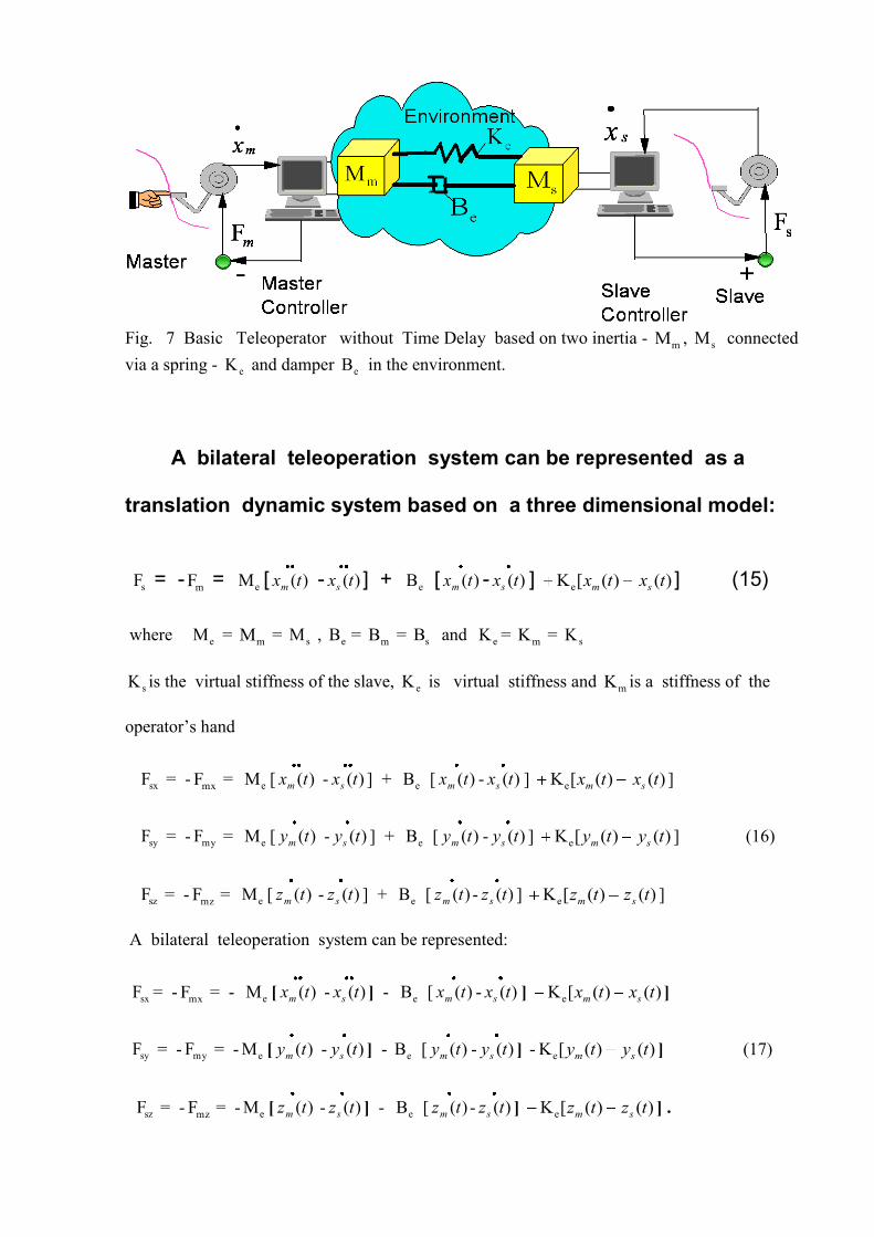
Fig. 7 Basic Teleoperator without Time Delay based on two inertia -
mM , sM connected
via a spring - eK and damper eB in the environment.
A bilateral teleoperation system can be represented as a
translation dynamic system based on a three dimensional model:
sF = - mF = eM [ )(txm - )(txs ] + eB [ )(txm - )(txs ] )([K e txm )(txs ] (15)
where eM = mM = sM , eB = mB = sB and eK = mK = sK
sK is the virtual stiffness of the slave, eK is virtual stiffness and mK is a stiffness of the
operator’s hand
sxF = - mxF = eM [ )(txm - )(txs ] + eB [ )(txm - )(txs ] )([K e txm )(txs ]
syF = - myF = eM [ )(tym - )(tys ] + eB [ )(tym - )(tys ] )([K e tym )(tys ] (16)
szF = - mzF = eM [ )(tzm - )(tzs ] + eB [ )(tzm - )(tzs ] )([K e tzm )(tzs ]
A bilateral teleoperation system can be represented:
sxF = - mxF = - eM [ )(txm - )(txs ] - eB [ )(txm - )(txs ] )([K e txm )(txs ]
syF = - myF = - eM [ )(tym - )(tys ] - eB [ )(tym - )(tys ] )([K- e tym )(tys ] (17)
szF = - mzF = - eM [ )(tzm - )(tzs ] - eB [ )(tzm - )(tzs ] )([K e tzm )(tzs ] .

The master will reflect the virtual contact force of the slave back to the operator and
the slave will follow the position of the master exactly because there is no time delay in this
case.
mxF = - sxF = eM [ )(txm - )(txs ] + eB [ )(txm - )(txs ] )([K e txm )(txs ]
myF = - syF = eM [ )(tym - )(tys ] + eB [ )(tym - )(tys ] )([Ke tym )(tys ] (18)
mzF = - szF = eM [ )(tzm - )(tzs ] -+ eB [ )(tzm - )(tzs ] )([Ke tzm )(tzs ]
MODELING OF DYNAMICS AND UNCERTAINTIES
BASED ON TRANSFER FUNCTION
Suppose we specify the dynamics in the environment such that
)(F
)()(
e s
sxsG e (45)
next we have
)(*)(F)( e sGssxe (46)
where )(sG some stable transfer function. Then the equation ( 37 ) will incorporate the
reflected wave :
)(F)()(2 e ssxbsvb es (47)
)(F)](*)([F)(2 ee ssGsbsvb es
(48)
or after the transformations
]1)([*)(F*)(2 e sGsbsvb es (49)
Now we can consider
T)()( tvtv sm
and at the master robot :

)(*2)()(Fm tvbtxbt mm
(50)
We wish to design )(Fm t at the master:
T)(*2)()(Fm tvbtxbt sm (51)
then choose
]1)([*)T(F**2)()(F em sGtbbtxbt em ( 52)
therefore we have the )(Fm t force on the master robot that can be controlled, with desired
characteristics and the desired transfer functions )(sG using additional elements (an example
damper), which are inserted into the P.D. PHANToM controller .
We can control the desired )(Fm t on the master robot by varying the transfer function
)(sG using the three dimensional model with the x,y,z axes :
]1)([*)T(F**2)()(F exmx sGtbbtxbt xem
]1)([*)T(F**2)()(F eymy sGtbbtxbt yemy (53)
]1)([*)T(F**2)()(F ezmz sGtbbtxbt zemz
It is very important for optimal design to create the best match of the impedance between
the P.D. controller and the wave transmission. We propose, using a layout as shown in
Niemeyer’s work, (see Fig. 41 ) for our visual model of the PHANToM robot.
We may add a noise or an uncertainties into the wave variable on slave robot )(tvs .
Suppose that the signal )(t is the one we wish to track. We want )(txe to follow the target in
space )(t . The tracking error in this case is desired :
)()( txtx eerror (54)

We further use three methods for getting of signal )(t on our model:
As a wave with tt sin*A)( ;
As random signal )(t , this signal is generated by the moving mouse along the x, y
(z signal is generated) in time as control events in model;
As one random signal )(t .
We would like errorx to be asymptotically stable such that
)(F
)()(
e s
sxsG e = which implies some stable transfer function (i.e. we have a stable
impedance in the environment).
We select )(svs in the environment to consist of two terms :
)(F)()(2 e ssxbsvb es = tracking error + impedance interaction + noise error + master
Hence
)(F)()(2 e ssxbsvb es = )()(][ 31
2 txteex m
tt
error (55)
Hence )()(F)( e tssxbe + )()( txt m
Hence btxbt m 2)()(Fm [ T)(tvs ]
btxbt m 2)()(Fm [ T)(t ]
btxbt m 2)()(Fm [ T)(t + )T(txm + )(t ] (56)
where T)(t = [ T)(tvs ]
IMPEDANCE MATCHED TELEOPERATOR

In this case, described by Niemeyer, the wave communications acts as a true admittance. I t
observes forces on both sides and updates the desired motions as needed. Both master and slave
are controlled via an impedance matched P.D. controller.
SLAVE AND MASTER CONTACT WITH ENVIRONMENT
Preliminary research with the PHANToM have shown that the time delay in the condition
of contact causes a very unstable process . However, to continue this research in needed in
more detail with the wave variable method.
FUTURE RESEARCH
Use Wave-Based Teleportation for the PHANToM with integrated IPVTS for different
variable parameters changing in wide limits:
a) wave variables b) single variable combinations of both velocity and force data c) for
large delays with methods including wave impedance matching, d) wave filtering and
wave controllers e) wave reflection g) research the Drifting Problem and three Feedback
Paths Problem.
We will change these combinations of parameters using the wave controllers based on
computer modeling in a real-time system with and without time delays. The possible
solutions and conditions of experiments will be utilize into a Knowledge Database. The goal of
these experiments is to compare the stability of the control system with the wave variables
using the different types of sensory information , for large delays and with methods including
wave impedance matching, the wave filtering, and wave controllers.
It allows us to use the advantage of the intelligent m-dimensional parametric control based on
IPVTS.
Run the experiment based on IPVTS together with the PHANToM with a predictor
incorporated inside the wave junction.

Run the experiments for target detection using IPVTS with the PHANToM based on
the different types of sensory information and in conjunction with the cues which work
together with the intelligent m-dimensional parametric control. Analyze the errors that
might occur in the control process . It is desired to use the advantage of the intelligent m-
dimensional parametric control based on IPVTS.
Use Transfer Functions H(s) = V(s)/U(s) to further illustrate in a Visual Model the
meaning and behavior of wave variables and systems as criteria for control.
Create the optimization system in IPVTS for the design Classic Elements in Wave Space
for basic controllers such as PHANToM Robot, Haptic Stick, 3D-Audio Computer
Controller and Computer Based MEMS Controller.
APPENDIX: Examples for short demonstration of the concepts of IPVTS
Fig. 1 The example of modeling for the airplane flight control

Fig 2 The example of modeling for the virtual 3D object control and virtual parameters
modeling in 3D space using master robot and slave robot.
Fig. 3 The spatial-oriented model based on reaction-diffusion equations for modeling
diffusion of chemical -A into structure of chemical – B.

Fig. 4 The model of the deformation process with damage of molecular links under the
action of forces Pi based on IPVTS methodology.
Fig. 5 The trajectory modeling for motion of multi-objects system with nonlinear trajectory
using Intelligent Parametric Visual Thinking System

Fig. 6 Virtual Sensors Network Architecture with parallel sensors hardware and smart multi-agent sensors system
on remote and locally distributed system
.
Fig. 7 Virtual Sensors Network Architecture with parallel sensors hardware and smart multi-
agent sensors system on remote and locally distributed system.

Fig. 8 Status control and monitoring for laser OSI Scintillometer based on smart multi-agent system.
Fig. 9 The remote teleoperation with wave variables based on Niemeyer ‘s work
[Niemeyer 1996].