Embed Size (px)
Citation preview

Intel® Pentium® III Processor Thermal Metrology for 068x family processors
Intel CONFIDENTIAL – Internal Use Only(until publication date)
October 1999
Intel ® Pentium ® III processorThermal Metrology for CPUID068h family processors
Document Number: 245301-001

Intel® Pentium® III Processor Thermal Metrology for 068x family processors
Intel CONFIDENTIAL – Internal Use Only(until publication date)
Information in this document is provided in connection with Intel products. No license, express or implied, by estoppel orotherwise, to any intellectual property rights is granted by this document. Except as provided in Intel's Terms and Conditionsof Sale for such products, Intel assumes no liability whatsoever, and Intel disclaims any express or implied warranty, relatingto sale and/or use of Intel products including liability or warranties relating to fitness for a particular purpose, merchantability,or infringement of any patent, copyright or other intellectual property right. Intel products are not intended for use in medical,life saving, or life sustaining applications.
Intel may make changes to specifications and product descriptions at any time, without notice.
Designers must not rely on the absence or characteristics of any features or instructions marked "reserved" or "undefined."Intel reserves these for future definition and shall have no responsibility whatsoever for conflicts or incompatibilities arisingfrom future changes to them.
The Pentium® III processor may contain design defects or errors known as errata which may cause the product to deviatefrom published specifications. Current characterized errata are available on request.
Contact your local Intel sales office or your distributor to obtain the latest specifications and before placing your product order.
Copies of documents which have an order number are referenced in this document, or other Intel literature, may be obtainedby calling 1-800-548-4725, or by visiting Intel’s website at http://www.intel.com.
Copyright © Intel Corporation 1999.
* Third-party brands and names are the property of their respective owners.
Intel® Pentium® III Processor Thermal Metrology for 068x family processors 3
Intel CONFIDENTIAL – Internal Use Only(until publication date)
CONTENTS
1 INTRODUCTION 41.1 Document Goals 4
1.2 Document Scope 4
1.3 References 4
1.4 Definition of Terms 4
2 S.E.C.C.2 and FC-PGA PROCESSOR PACKAGING TECHNOLOGY 52.1 Single Edge Contact cartridge 2 5
2.2 Flip Chip Plastic Grid Array 5
3 THERMAL SPECIFICATIONS 63.1 Thermal Junction Temperature 6
3.2 Power 6
4 SECC2-FC-PGA Metrology 64.1 THERMAL JUNCTION MEASUREMENT TECHNIQUE 7
4.2 Background 7
4.2.1 Procedure Overview: 9
4.2.2 Validation Method 15
5 Appendix 185.1 BACKGROUND ON THERMAL RESISTANCE 18
5.1.1 Thermal Resistance 18
5.1.2 Thermal Solution Performance 18
5.2 About the HIPOWER Application 19
5.2.1 Executing the High Power Application Software 20

Intel® Pentium® III Processor Thermal Metrology for 068x family processors 4
Intel CONFIDENTIAL – Internal Use Only(until publication date)
1 INTRODUCTION
This document describes the procedure for measuring the core junction temperature on Intel� Pentium� III(068xh family) processors in the following form factors: Single Edge Connector Cartridge 2 (SECC2) orthe Flip Chip Plastic Grid Array (FCPGA). The metrology involves use of the High Power Applicationsoftware Rev 1.0 (“HIPWR30.EXE”) to perform system level analysis of cooling solutions. Using themethodologies described in this document, a system designer will be able to validate system-coolingsolutions for compatibility with the specified processor worst-case power consumption.
1.1 Document GoalsThe goal of this document is to provide a method to measure and ensure compliance of a heat sinks abilityto keep the die temperature of a Pentium III processor in either the SECC2 or FCPGA package, in the068xH family, within the specification requirements.
1.2 Document ScopeThis document discusses techniques in thermal measurement only for Pentium III 068xh family processorsin the SECC2 and FC-PGA processors primarily intended for the desktop system
1.3 References� Pentium® III Processor Datasheet (Order Number 244452)
� Pentium® III Processor for the PGA370 Socket at 500MHz and 550 MHz (Order number 245264-001)
� Pentium® III Processor Specification Update
� SC242 Connector Design Guidelines
� Datasheets and Specification Updates available at http://developer.intel.com
1.4 Definition of Terms� Tambient-LOCAL - the measured ambient temperature locally surrounding the processor. The
ambient temperature should be measured about 0.3” “upstream” of a passive heat sink, or at the 0.3”above the fan inlet for an active heat sink.
� Tambient external - the measured ambient temperature outside of the system.
� Tambient-MAX - the target worst-case local ambient temperature. This can be determined by placingthe system in maximum external temperature conditions and measuring the ambient temperaturelocally surrounding the processor. Under these conditions Tambient-local = Tambient-Max. This canalso be determined by simultaneously measuring the Tambient-external and Tambient-local with thefollowing equation: Tambient-max = Tambient-OEM - Tambient-external + Tambient-local.(Thisequation assumes a thermally linear system; i.e. No temperature controlled fans)
Intel® Pentium® III Processor Thermal Metrology for 068x family processors 5
Intel CONFIDENTIAL – Internal Use Only(until publication date)
� Tambient-OEM - the target worst-case ambient temperature at a given external system location asdefined by the system designer (OEM).
� Tjunction-MAX - the maximum core junction temperature of the processor, as specified in theprocessor datasheet.
� Tjunction-HIPWER30 - the measured core junction temperature of the processor while running theHigh Power Application software (“HIPWR30.EXE”).
� Tjunction-CAL - the calculated thermal junction temperature obtained when doing a validation test.
� Tjunction-OFFSET - the worst-case difference between the thermal reading from the on-die thermaldiode and the hottest location in the processor’s core, as specified in the processor datasheet.
� Tsensor-OFFSET - the measurement error for a diode connected to a thermal measure device asspecified in the appropriate the device datasheet.
� �Junction-ambient - the thermal resistance between the processor’s core junction and the ambient air.This is defined and controlled by the system thermal solution.
� Pmax - the maximum processor power, as specified in the processor’s datasheet.
� SC242 Connector - Slot Connector 242 (242 contacts) Formally referred to as "Slot 1". The connectoron a baseboard where an Intel� Pentium� III or Pentium II processor in the SECC2 package isinstalled.
� PGA370 – socket connector that is installed on a baseboard where an Intel FCPGA processor isinstalled.
2 S.E.C.C.2 and FC-PGA PROCESSOR PACKAGING TECHNOLOGYThe Intel Pentium III processors are delivered in either the SECC2 or FCPGA packaging technology. Thefollowing sections provide an overview of each type.
2.1 Single Edge Contact cartridge 2 (SECC2)The Pentium III processor is available in the SECC2 packaging technology. This is an Organic Land GridArray (OLGA) package mounted to an SECC2 type package. The OLGA contains the microprocessorsilicon with an integrated second level cache, referred to as an "L2". The processor connects to themotherboard through a SC242 socket connector.
2.2 Flip Chip Plastic Grid ArrayThe Pentium III processor introduced a new packaging technology known as a Flip Chip Plastic Grid Array(FC-PGA). The FC-PGA contains the microprocessor silicon with an integrated second level cache,referred to as an "L2". The processor connects to the motherboard through a socket referred to as PGA370Socket.

Intel® Pentium® III Processor Thermal Metrology for 068x family processors 6
Intel CONFIDENTIAL – Internal Use Only(until publication date)
3 THERMAL SPECIFICATIONSThe processor power dissipation and the processor Tj-offset can be found in the applicable processordatasheet; please refer to this document to verify the actual thermal specifications for a particularprocessor. Document can be found at http://developer.intel.com/design/PentiumIII/datashts/. While theprocessor core dissipates the majority of the thermal power, the system designer should also be aware ofthe thermal power dissipated by the second level cache. Systems should design for the highest possiblethermal power, even if a processor with a lower power requirement is planned, this will allow the design toaccept future processors interchangeably.
3.1 Thermal Junction TemperatureThe core thermal junction temperature reading is used to evaluate the system's thermal solution. Themeasurement of the core junction temperature of a live processor using either the SECC2 packagingtechnology or the FC-PGA processor core is critical to the validation of a OEM chassis and heat sinkthermal designs. A thermal diode is independently routed off the processor core to the SC242 connector orthe PGA370 socket to assist in evaluating the junction temperature. This is the same diode that has beenused by DMI client software to monitor processor temperature since the introduction of the Intel SC242processor. For more information on the thermal diode, refer to the processor datasheet.
3.2 PowerThe processor core dissipates the majority of the thermal power, however, the system designer should alsobe aware of the thermal power dissipated by the second level cache. Systems should design for the highestpossible thermal power. In the SECC2 and FC-PGA packages, the L2 cache is integrated into the die, soheat is dissipated only through the die. The processor power is the total of heat dissipated from the core andL2 cache. As described in the processor datasheet, system thermal designers should assume that the bulk ofthe power must be removed from the core area, which is smaller that the entire processors die area.
4 SECC2/FC-PGA MetrologyThis section describes the procedure for measuring the core junction temperature for Pentium III processorsin the Single Edge Contact Cartridge 2 (SECC2) package with OLGA core packaging technology and forprocessors in the Flip Chip Plastic Grid Array package (FC-PGA). The metrology involves use of the HighPower Application software (“HIPWR30.EXE”) to perform system level analysis of cooling solutions.Using the methodologies described in this section, a system designer will be able to validate system-cooling solutions for compatibility with the specified processor worst-case power consumption
Note:While it is tempting to place a measurement device on the top of the OLGA package the results can not becorrelated to Tjunction. Extensive experiments conducted by Intel using a top of the OLGA packagemeasurement method proved the results were very erratic.

Intel® Pentium® III Processor Thermal Metrology for 068x family processors 7
Intel CONFIDENTIAL – Internal Use Only(until publication date)
4.1 THERMAL JUNCTION MEASUREMENT TECHNIQUE
Note: The purpose of this procedure is to explain how to take junction (die) level temperaturemeasurements on Intel processors using the Analog Devices EVAL-AD1021 Kit. A different kit could beused in place of the Analog Devices Kit, however it is the responsibility of the user to ensure the correctoffsets are determined.
4.2 Background The measurement of the junction temperature of a live processor using SECC2 packagingtechnology and OLGA processor core, or the FC-PGA package, is critical to validate an OEM chassis andheat sink thermal design. A thermal diode is independently routed off the processor core to the SC242connector/PGA370 Socket to assist in evaluating the junction temperature. In order to simplify themeasurement of the diode temperature, use the Analog Devices EVAL-AD1021 Kit. The Analog DevicesEVAL-AD1021 kit requires no diode calibration.
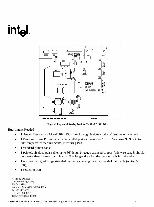
The Analog Devices EVAL-AD1021 Kit is a tool provided by Analog Devices that includes theAD1021 temperature sensor IC and all the additional circuitry and software needed to take temperaturemeasurements with the AD1021 and a typical PC (see Figure 1 for layout of the EVAL kit). The AD1021is essentially an 8 bit A/D converter and integrated controller which measures the difference between thevoltage drop across a diode using 2 exciting currents to derive a junction temperature. The 8 bittemperature data is accessed by external applications via the 2-wire SMBus. The EVAL kit conditions theoutput from the AD1021 to be read by a standard 25 pin parallel port terminal on a PC. Software isincluded with the EVAL kit to display temperature measurements on a PC running Windows 3.1 orWindows 95/98 OS. See the AD1021 and Analog Devices EVAL-AD1021 Kit datasheets for moredetailed information on the measurement tools.
Intel® Pentium® III Processor Thermal Metrology for 068x family processors 8
Intel CONFIDENTIAL – Internal Use Only(until publication date)
Figure 1 Layout of Analog Devices EVAL-AD1021 Kit
Equipment Needed
� 1 Analog Devices EVAL-AD1021 Kit from Analog Devices Products1 (software included)
� 1 Pentium� class PC with available parallel port and Windows* 3.1 or Windows 95/98 OS totake temperature measurements (measuring PC)
� 1 standard printer cable
� 1 twisted, shielded pair cable, up to 56” long, 24 gauge stranded copper (this wire can, & should,be shorter than the maximum length. The longer the wire, the more error is introduced.)
� 1 insulated wire, 24 gauge stranded copper, same length as the shielded pair cable (up to 56”long)
� 1 soldering iron
1 Analog DevicesOne Technology WayPO Box 9106Norwood MA, 02062-9106, USATel 781-329-4700Fax: 781-326-8703http://www.analog.com
Intel® Pentium® III Processor Thermal Metrology for 068x family processors 9
Intel CONFIDENTIAL – Internal Use Only(until publication date)
� 1 live chassis with processor diode to be evaluated (test PC)
� HIPWR30.EXE application (available from your local Intel Representative)
4.2.1 Procedure Overview:The exact procedure used to perform a test may vary slightly depending on the measurement kitused and whether the software has already been installed on a test/host system. Please varyprocedure as appropriate.
The recommended procedure for an Analog Devices test kit that has not been previously used is asfollows
� Establish electrical connections� Install the measurement software on the test PC� Perform a No-power test� Perform a power test� Perform a validation test� Complete calculation to determine if thermal solution is keeping processor within specified
Tj.
4.2.1.1 Electrical Hookups for SECC2 processors
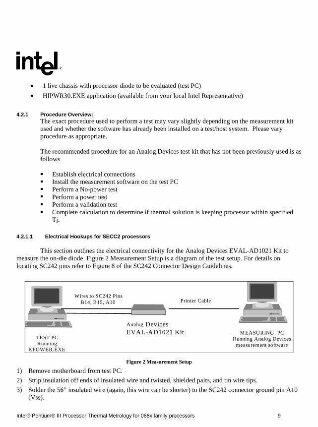
This section outlines the electrical connectivity for the Analog Devices EVAL-AD1021 Kit tomeasure the on-die diode. Figure 2 Measurement Setup is a diagram of the test setup. For details onlocating SC242 pins refer to Figure 8 of the SC242 Connector Design Guidelines.
MEASURING PCRunning Analog Devices
measurement software
TEST PCRunning
KPOWER.EXE
Analog DevicesEVAL-AD1021 Kit
Wires to SC242 PinsB14, B15, A10 Printer Cable
Figure 2 Measurement Setup
1) Remove motherboard from test PC.
2) Strip insulation off ends of insulated wire and twisted, shielded pairs, and tin wire tips.
3) Solder the 56” insulated wire (again, this wire can be shorter) to the SC242 connector ground pin A10(Vss).
Intel® Pentium® III Processor Thermal Metrology for 068x family processors 10
Intel CONFIDENTIAL – Internal Use Only(until publication date)
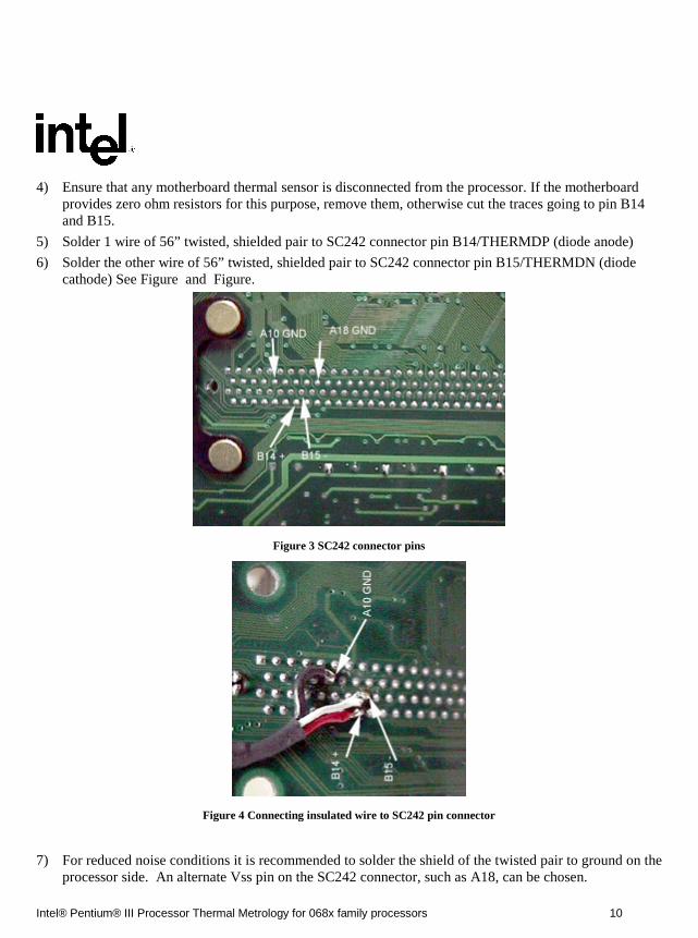
4) Ensure that any motherboard thermal sensor is disconnected from the processor. If the motherboardprovides zero ohm resistors for this purpose, remove them, otherwise cut the traces going to pin B14and B15.
5) Solder 1 wire of 56” twisted, shielded pair to SC242 connector pin B14/THERMDP (diode anode)
6) Solder the other wire of 56” twisted, shielded pair to SC242 connector pin B15/THERMDN (diodecathode) See Figure and Figure.
Figure 3 SC242 connector pins
Figure 4 Connecting insulated wire to SC242 pin connector
7) For reduced noise conditions it is recommended to solder the shield of the twisted pair to ground on theprocessor side. An alternate Vss pin on the SC242 connector, such as A18, can be chosen.
Intel® Pentium® III Processor Thermal Metrology for 068x family processors 11
Intel CONFIDENTIAL – Internal Use Only(until publication date)
8) Tape the ground wire and twisted, shielded pair wires to the backside of the motherboard to relievestress on the solder joints. Route wires out to edge of motherboard which has enough clearance toallow wires to pass through
9) Replace motherboard in chassis (you may wish to take room temperature measurements on processorbefore replacing all chassis components to verify good solder joints)
10) Route the wires out of the chassis through a PCI slot (or other convenient hole in chassis), taking careto ensure the wires do not obstruct any critical airflow paths
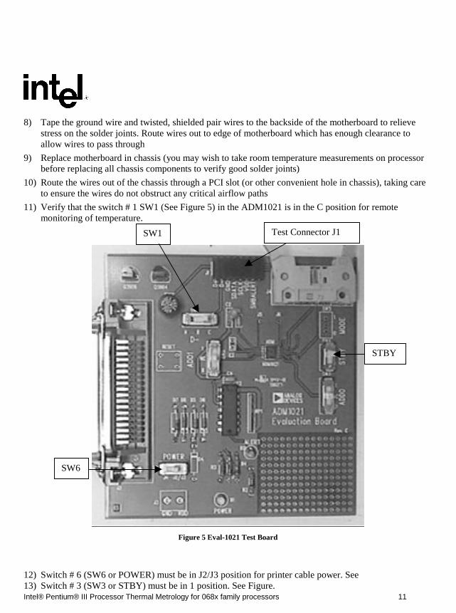
11) Verify that the switch # 1 SW1 (See Figure 5) in the ADM1021 is in the C position for remotemonitoring of temperature.
Figure 5 Eval-1021 Test Board
12) Switch # 6 (SW6 or POWER) must be in J2/J3 position for printer cable power. See13) Switch # 3 (SW3 or STBY) must be in 1 position. See Figure.
Test Connector J1SW1
STBY
SW6
Intel® Pentium® III Processor Thermal Metrology for 068x family processors 12
Intel CONFIDENTIAL – Internal Use Only(until publication date)
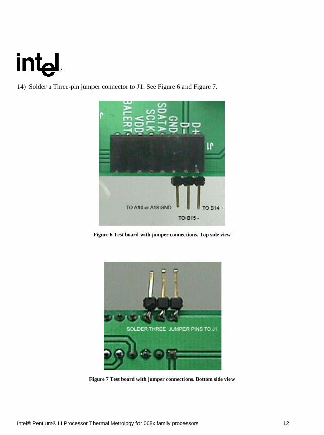
14) Solder a Three-pin jumper connector to J1. See Figure 6 and Figure 7.
Figure 6 Test board with jumper connections. Top side view
Figure 7 Test board with jumper connections. Bottom side view
Intel® Pentium® III Processor Thermal Metrology for 068x family processors 13
Intel CONFIDENTIAL – Internal Use Only(until publication date)
15) Connect the other end of the twisted pair cable to the three jumper pins on J1on the ADM1021 card.The positive lead (coming from B14) to D+, the negative lead (coming from B15) to D- and the shieldto GND. See , Figure 6 and Figure 7
16) Using the parallel port cable, connect measuring PC to kit
17) Proceed to software installation.
4.2.1.2 Electrical Connections for an Intel FCPGA processor1) Remove motherboard from test PC.
2) Strip insulation off ends of insulated wire and twisted, shielded pairs, and tin wire tips.
3) Ensure that any motherboard thermal sensor is disconnected from the processor. If the motherboardprovides zero ohm resistors for this purpose, remove them, otherwise cut the traces going to AL31 andAL29.
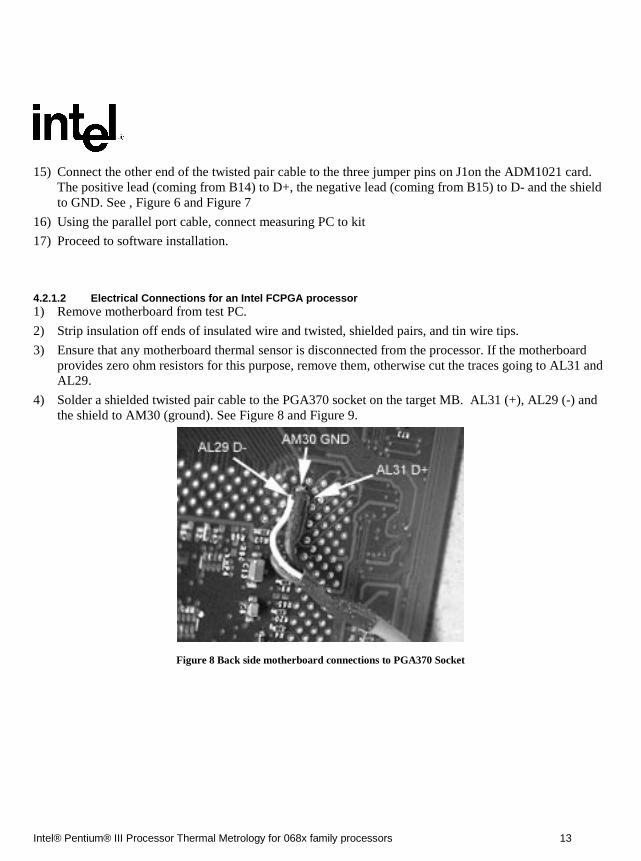
4) Solder a shielded twisted pair cable to the PGA370 socket on the target MB. AL31 (+), AL29 (-) andthe shield to AM30 (ground). See Figure 8 and Figure 9.
Figure 8 Back side motherboard connections to PGA370 Socket
Intel® Pentium® III Processor Thermal Metrology for 068x family processors 14
Intel CONFIDENTIAL – Internal Use Only(until publication date)
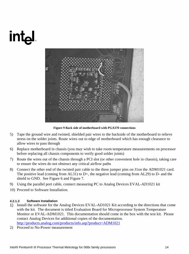
Figure 9 Back side of motherboard with PGA370 connections
5) Tape the ground wire and twisted, shielded pair wires to the backside of the motherboard to relievestress on the solder joints. Route wires out to edge of motherboard which has enough clearance toallow wires to pass through
6) Replace motherboard in chassis (you may wish to take room temperature measurements on processorbefore replacing all chassis components to verify good solder joints)
7) Route the wires out of the chassis through a PCI slot (or other convenient hole in chassis), taking careto ensure the wires do not obstruct any critical airflow paths
8) Connect the other end of the twisted pair cable to the three jumper pins on J1on the ADM1021 card.The positive lead (coming from AL31) to D+, the negative lead (coming from AL29) to D- and theshield to GND. See Figure 6 and Figure 7.
9) Using the parallel port cable, connect measuring PC to Analog Devices EVAL-AD1021 kit
10) Proceed to Software Installation.
4.2.1.3 Software Installation1) Install the software for the Analog Devices EVAL-AD1021 Kit according to the directions that come
with the kit. The document is titled Evaluation Board for Microprocessor System TemperatureMonitor or EVAL-ADM1021. This documentation should come in the box with the test kit. Pleasecontact Analog Devices for additional copies of the documentation.http://products.analog.com/products/info.asp?product=ADM1021
2) Proceed to No-Power measurement

Intel® Pentium® III Processor Thermal Metrology for 068x family processors 15
Intel CONFIDENTIAL – Internal Use Only(until publication date)
4.2.1.4 No-Power (test PC) Measurement This section is optional and describes how to take no-power (on the test PC) temperaturemeasurements on the processor diode. It is useful to gain confidence in the Analog Devices EVAL-ADM1021 kit.
1) Start the test program from the floppy or hard drive by starting the Analog Devices application
2) Follow the directions supplied by Analog Devices in the document titled Evaluation Board forMicroprocessor System Temperature Monitor or EVAL-ADM1021.
3) If there are no addressing problems, a window containing the temperature measurement and datacollection control features will start up (If there are slave addressing problems, check to make sure thatall electrical connections are properly made and electrical switches are in their correct positions. If thatdoes not solve the addressing problem, please refer to the Analog Devices EVAL-ADM1021 datasheet to resolve the problem)
4) Select a measurement rate of 1 Hz
5) The temperatures displayed should read ambient temperature (provided the test processor has not beenheated up).
6) Proceed to Power-On Temperature Measurement
4.2.1.5 Power-On (test PC) Temperature Measurement This process outlines how to use the processor diode to take temperature measurements while theprocessor is powered on. This is the procedure that should be used to validate chassis and heat sink thermaldesigns while running the high power application software.
1) Turn on the test PC and run the high power application software
2) Allow the High Power Application software to run for at least 1 hour to allow all chassis componentsto come to thermal equilibrium
3) Note temperature displayed in the “remote” box. This is the test processor Tjunction-HIPWR30temperature.
4) You are now ready to perform a validation test.
4.2.2 Validation Method
This section assumes a familiarity with the terms defined in Section 1.4. This section describes thevalidation Method for CPUID Model 068x processors using the SECC2 or FCPGA package.
4.2.2.1 Validation Method for CPUID Model 068x processors using the SECC2 packages.Performing a simplified validation of the cooling solution on the junction temperature for maximumspecified processor power dissipation values requires the measurement of Tjunction-hipwr30 andTambient-local temperatures while executing the High Power Application software.
Intel® Pentium® III Processor Thermal Metrology for 068x family processors 16
Intel CONFIDENTIAL – Internal Use Only(until publication date)
1) The system and processor under analysis should be prepared to gather Tjunction-hipwr30 temperaturemeasurement as described in Section 4 and the Tambient-local temperature just “upstream” of apassive heat sink or at the fan inlet for an active heat sink (measured 0.3 inches above the fan hub).
2) Once the system is ready for data collection, the “HIPWR30.EXE” High Power Application softwareshould be executed.
3) With “HIPWR30.EXE” executing, allowing system temperatures to stabilize for one hour, gather theTjunction-HIPWR30 and Tambient-local temperature measurements.
4) Calculate the Final Value of Tjunction using Equation 1 & compare it to the datasheet junctiontemperature specification.
Equation 1
Tjunction-HIPWR30 (diode) + (Tambient-max - Tambient-local) + Tjunction-offset1 + MeasurementError2 <= datasheet Tj specification
1. Tjunction-offset is available from the processor datasheet
2. Measurement error is the diode kit measurement error. It can be determined through the course of ameasurement capability study or estimated by the diode kit datasheet.
Note:
For systems with non-linear thermal behavior, like those with thermally controlled fan(s), the systemdesigner should exercise caution to ensure that the processor temperature specifications are met given thedependencies on airflow and different fan activation patterns. The change in airflow effectively changesthe �junction_ambient of the processor’s thermal solution. Therefore, the various system conditions shouldbe evaluated when determining the worst-case target Tambient-Max, Tambient-local and Tjunction-HIPWR30.
For example, in determining compliance of a 600MHz processor to the Tjunction-max specification asstated in the processor’s datasheet, the following illustrates the approach:
Stated Conditions:
Processor Core Frequency = 600 MHz
Tjunction-Max = 82�C (Tjunction that is found in the appropriate Intel processor datasheet)
Tjunction-HIPWR30 = 68.0 �C (measured temperature running HIPWR30.EXE)
Tambient-max = 45�C (the target worst-case local ambient temperature)
Tambient-local = 35.0 �C (measured ambient temp.)
Toffset = 2.9�C (This values is found in the appropriate Intel processor datasheet)
Measurement Error = 1�C (Measurement Error for Analog Devices EVAL-ADM1021 Kit.

Intel® Pentium® III Processor Thermal Metrology for 068x family processors 17
Intel CONFIDENTIAL – Internal Use Only(until publication date)
Using the equation:
Tjunction-CAL = Tjunction-HIPWR30 + (Tambient-max-Tambient-local) + Tjunction-offset +Measurement Error
Tjunction-CAL = 68.0�C + (45�C – 35�C) + 2.9�C + 1�C
Tjunction-CAL = 81.9�C
Because Tjunction-CAL (81.9�C) <= Tjuntion-MAX (82�C) this thermal solution example is within theguidelines.

Intel® Pentium® III Processor Thermal Metrology for 068x family processors 18
Intel CONFIDENTIAL – Internal Use Only(until publication date)
5 Appendix
5.1 BACKGROUND ON THERMAL RESISTANCE
5.1.1 Thermal Resistance
The thermal resistance value for the core-to-ambient (�JA) in SECC2/FC-PGA packages is used as ameasure of the cooling solution's thermal performance. Thermal resistance is measured in units of°C/W. The thermal resistance of the core junction-to-ambient, �JA, is comprised of the processorcore (OLGA) thermal resistance and the sink-to-local ambient thermal resistance (�SA). �SA isstrongly dependent on the thermal conductivity and thickness of the thermal interface material andthe heat sink's thermal characteristics .
The thermal parameters are related by the following equations (S.E.C.C.2/FC-PGA):
�JA = (Tjunction - TLA) / PD
�JA = �JS +�SA
Where:
�JA = Thermal resistance from junction-to-local ambient (°C/W)
Tjunction= Processor thermal plate temperature (°C)
TLA = Local ambient temperature in chassis around processor (°C)
PD = Device power dissipation (W) (assume no power goes to the other side)
�JS = Thermal resistance from junction-to-sink (°C/W)
�SA = Thermal resistance from heatsink-to-local ambient (°C/W)
5.1.2 Thermal Solution Performance
For SECC2 packages, all processor thermal solutions should attach to the processor cartridge. The FC-PGAthermal solution is similar to the Plastic Pin Grid Array (PPGA) Thermal solutions, with the heatsinkattached to the top of the substrate. The lower the thermal resistance between the processor and the localambient air, the more efficient the thermal solution. The required �ja is dependent upon the maximumallowed processor temperature (Tjunction), the local ambient temperature (TLA) and the processor power(Pmax). This can be expressed in the following mathematical equation:
�JA = (Tjunction - TLA) / Pmax
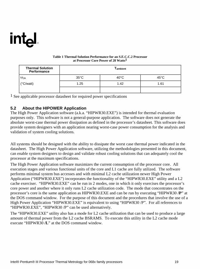
TLA is a function of the system design.Table 1 provides the example resultant thermal solution performance for Intel SECC2 processor at differentlocal ambient air temperatures around the processor.
Intel® Pentium® III Processor Thermal Metrology for 068x family processors 19
Intel CONFIDENTIAL – Internal Use Only(until publication date)
Table 1 Thermal Solution Performance for an S.E.C.C.2 Processorat Processor Core Power of 28 Watts1
Thermal SolutionPerformance
Tambient
�JA 35°C 40°C 45°C
(°C/watt) 1.25 1.42 1.61
1 See applicable processor datasheet for required power specifications
5.2 About the HIPOWER Application The High Power Application software (a.k.a. “HIPWR30.EXE”) is intended for thermal evaluationpurposes only. This software is not a general-purpose application. The software does not generate theabsolute worst-case thermal power dissipation as defined in the processor’s datasheet. This software doesprovide system designers with an application nearing worst-case power consumption for the analysis andvalidation of system cooling solutions.
All systems should be designed with the ability to dissipate the worst case thermal power indicated in thedatasheet. The High Power Application software, utilizing the methodologies presented in this document,can enable system designers to design and validate robust cooling solutions that can adequately cool theprocessor at the maximum specifications.
The High Power Application software maximizes the current consumption of the processor core. Allexecution stages and various functional units of the core and L1 cache are fully utilized. The softwareperforms minimal system bus accesses and with minimal L2 cache utilization newer High PowerApplication (“HIPWR30.EXE”) incorporates the functionality of the “HIPWR30.EXE” utility and a L2cache exerciser. “HIPWR30.EXE” can be run in 2 modes, one in which it only exercises the processor’score power and another where it only runs L2 cache utilization code. The mode that concentrates on theprocessor’s core is the same application as HIPWR30.EXE and can be run by executing “HIPWR30 /P” atthe DOS command window. For the purpose of this document and the procedures that involve the use of aHigh Power Application “HIPWR30.EXE” is equivalent to using “HIPWR30 /P”. For all references to“HIPWR30.EXE”, “HIPWR30 /P” can be used alternatively.
The “HIPWR30.EXE” utility also has a mode for L2 cache utilization that can be used to produce a largeamount of thermal power from the L2 cache BSRAMS. To execute this utility in the L2 cache modeexecute “HIPWR30 /L” at the DOS command window.

Intel® Pentium® III Processor Thermal Metrology for 068x family processors 20
Intel CONFIDENTIAL – Internal Use Only(until publication date)
5.2.1 Executing the High Power Application Software
The High Power Application software is a 32 bit Windows* NT or Windows* 95/98 application. Theapplication should be executed from a DOS window command prompt from within the Windows NTor Windows 95/98 environment, and not from a DOS only environment. The High Power Applicationsoftware puts the processor into an infinite loop and locks the command prompt environment. The“HIPWR30.EXE” utility has an on-screen message with version number information and usage help. Tohalt execution of the application, use the Windows NT Task Manager* or Windows 95/98 Task Bar* tostop execution of the command prompt environment. For maximum processor power consumption, thesoftware should be the only application executing on the system under evaluation. It is recommendedthat the Windows NT or Windows 95/98 operating environment be configured to the default OS settings.


UNITED STATES, Intel Corporation2200 Mission College Blvd., P.O. Box 58119, Santa Clara, CA 95052-8119
Tel: +1 408 765-8080
JAPAN, Intel Japan K.K.5-6 Tokodai, Tsukuba-shi, Ibaraki-ken 300-26
Tel: + 81-29847-8522
FRANCE, Intel Corporation S.A.R.L.1, Quai de Grenelle, 75015 Paris
Tel: +33 1-45717171
UNITED KINGDOM, Intel Corporation (U.K.) Ltd.Pipers Way, Swindon, Wiltshire, England SN3 1RJ
Tel: +44 1-793-641440
GERMANY, Intel GmbHDornacher Strasse 1
85622 Feldkirchen/ MuenchenTel: +49 89/99143-0
HONG KONG, Intel Semiconductor Ltd.32/F Two Pacific Place, 88 Queensway, Central
Tel: +852 2844-4555
CANADA, Intel Semiconductor of Canada, Ltd.190 Attwell Drive, Suite 500Rexdale, Ontario M9W 6H8
Tel: +416 675-2438
BRAZIL, Intel Semicondutores do BrasilCentro Empresarial Nações Unidas - Edifício Torre Oeste
Av. das Nações Unidas, 12.901 - 18o. andar - Brooklin Novo04578.000 São Paulo - S.P. – Brasil
Tel: +55-11-5505-2296