Embed Size (px)
Citation preview
Order Number: 315279 - 003US
Intel® CoreTM 2 Duo E6400, E4300, and Intel® Pentium® Dual-Core E2160 ProcessorThermal Design Guide
October 2007
Intel® CoreTM 2 Duo E6400, E4300, and Intel® Pentium® Dual-Core E2160 ProcessorTDG October 20072 Order Number: 315279 - 003US
Legal Lines and DisclaimersINFORMATION IN THIS DOCUMENT IS PROVIDED IN CONNECTION WITH INTEL® PRODUCTS. NO LICENSE, EXPRESS OR IMPLIED, BY ESTOPPEL OR OTHERWISE, TO ANY INTELLECTUAL PROPERTY RIGHTS IS GRANTED BY THIS DOCUMENT. EXCEPT AS PROVIDED IN INTEL’S TERMS AND CONDITIONS OF SALE FOR SUCH PRODUCTS, INTEL ASSUMES NO LIABILITY WHATSOEVER, AND INTEL DISCLAIMS ANY EXPRESS OR IMPLIED WARRANTY, RELATING TO SALE AND/OR USE OF INTEL PRODUCTS INCLUDING LIABILITY OR WARRANTIES RELATING TO FITNESS FOR A PARTICULAR PURPOSE, MERCHANTABILITY, OR INFRINGEMENT OF ANY PATENT, COPYRIGHT OR OTHER INTELLECTUAL PROPERTY RIGHT. Intel products are not intended for use in medical, life saving, life sustaining, critical control or safety systems, or in nuclear facility applications.
Intel may make changes to specifications and product descriptions at any time, without notice. Designers must not rely on the absence or characteristics of any features or instructions marked “reserved” or “undefined.” Intel reserves these for future definition and shall have no responsibility whatsoever for conflicts or incompatibilities arising from future changes to them. The information here is subject to change without notice. Do not finalize a design with this information.
The products described in this document may contain design defects or errors known as errata which may cause the product to deviate from published specifications. Current characterized errata are available on request.
Contact your local Intel sales office or your distributor to obtain the latest specifications and before placing your product order.
Copies of documents which have an order number and are referenced in this document, or other Intel literature, may be obtained by calling 1-800-548-4725, or by visiting Intel’s Web Site.
Intel processor numbers are not a measure of performance. Processor numbers differentiate features within each processor family, not across different processor families. See http://www.intel.com/products/processor_number for details.
Code Names are only for use by Intel to identify products, platforms, programs, services, etc. (“products”) in development by Intel that have not been made commercially available to the public, i.e., announced, launched or shipped. They are never to be used as “commercial” names for products. Also, they are not intended to function as trademarks.
BunnyPeople, Celeron, Celeron Inside, Centrino, Centrino logo, Core Inside, FlashFile, i960, InstantIP, Intel, Intel logo, Intel386, Intel486, Intel740, IntelDX2, IntelDX4, IntelSX2, Intel Core, Intel Inside, Intel Inside logo, Intel. Leap ahead., Intel. Leap ahead. logo, Intel NetBurst, Intel NetMerge, Intel NetStructure, Intel SingleDriver, Intel SpeedStep, Intel StrataFlash, Intel Viiv, Intel vPro, Intel XScale, Itanium, Itanium Inside, MCS, MMX, Oplus, OverDrive, PDCharm, Pentium, Pentium Inside, skoool, Sound Mark, The Journey Inside, VTune, Xeon, and Xeon Inside are trademarks of Intel Corporation in the U.S. and other countries.
*Other names and brands may be claimed as the property of others.
Copyright © 2007, Intel Corporation. All rights reserved.
Intel® CoreTM 2 Duo E6400, E4300, and Intel® Pentium® Dual-Core E2160 ProcessorOctober 2007 TDGOrder Number: 315279 - 003US 3
Intel® CoreTM 2 Duo E6400, E4300, and Intel® Pentium® Dual-Core E2160 Processor
Contents
1.0 Introduction ..............................................................................................................71.1 Document Goals and Scope ..................................................................................7
1.1.1 Importance of Thermal Management...........................................................71.1.2 Document Goals.......................................................................................71.1.3 Document Scope ......................................................................................7
1.2 References .........................................................................................................91.3 Definition of Terms ..............................................................................................9
2.0 Processor Thermal/Mechanical Information ............................................................ 112.1 Mechanical Requirements ................................................................................... 11
2.1.1 Processor Package.................................................................................. 112.1.2 Heatsink Attach ..................................................................................... 12
2.2 Thermal Requirements ....................................................................................... 142.2.1 Processor Case Temperature.................................................................... 142.2.2 Thermal Profile ...................................................................................... 152.2.3 TCONTROL ................................................................................................. 16
2.3 Heatsink Design Considerations........................................................................... 172.3.1 Heatsink Size......................................................................................... 172.3.2 Heatsink Mass........................................................................................ 182.3.3 Package IHS Flatness.............................................................................. 182.3.4 Thermal Interface Material....................................................................... 18
2.4 System Thermal Solution Considerations .............................................................. 192.4.1 Chassis Thermal Design Capabilities.......................................................... 192.4.2 Improving Chassis Thermal Performance ................................................... 192.4.3 Summary.............................................................................................. 19
2.5 System Integration Considerations ...................................................................... 20
3.0 Thermal Metrology .................................................................................................. 213.1 Characterizing Cooling Performance Requirements................................................. 21
3.1.1 Example................................................................................................ 223.2 Processor Thermal Solution Performance Assessment............................................. 233.3 Local Ambient Temperature Measurement Guidelines ............................................. 233.4 Processor Case Temperature Measurement Guidelines............................................ 25
4.0 Thermal Management Logic and Thermal Monitor Feature ....................................... 264.1 Processor Power Dissipation................................................................................ 264.2 Thermal Monitor Implementation......................................................................... 26
4.2.1 PROCHOT# Signal .................................................................................. 274.2.2 Thermal Control Circuit ........................................................................... 274.2.3 Thermal Monitor 2 .................................................................................. 284.2.4 Operation and Configuration .................................................................... 294.2.5 On-Demand Mode .................................................................................. 304.2.6 System Considerations............................................................................ 304.2.7 Operating System and Application Software Considerations.......................... 314.2.8 THERMTRIP# Signal ............................................................................... 314.2.9 Cooling System Failure Warning ............................................................... 314.2.10 Digital Thermal Sensor............................................................................ 314.2.11 Platform Environmental Control Interface (PECI) ........................................ 32
5.0 Intel® Reference Thermal Solution.......................................................................... 335.1 Thermal Solution Requirements........................................................................... 335.2 PICMG 1.3 Form Factor ...................................................................................... 345.3 ATX/BTX form factors ........................................................................................ 36
Intel® CoreTM 2 Duo E6400, E4300, and Intel® Pentium® Dual-Core E2160 Processor—
Intel® CoreTM 2 Duo E6400, E4300, and Intel® Pentium® Dual-Core E2160 ProcessorTDG October 20074 Order Number: 315279 - 003US
5.4 Altitude ............................................................................................................365.5 Geometric Envelope for Intel Reference PICMG 1.3 Thermal Mechanical Design ..........37
6.0 Intel® Quiet System Technology (Intel® QST).........................................................386.1 Intel® QST Algorithm .........................................................................................38
6.1.1 Output Weighting Matrix ..........................................................................396.1.2 Proportional-Integral-Derivative (PID) .......................................................39
6.2 Board and System Implementation of Intel® QST ..................................................416.3 Intel® QST Configuration and Tuning....................................................................436.4 Fan Hub Thermistor and Intel® QST .....................................................................43
A LGA775 Socket Heatsink Loading .............................................................................44A.1 LGA775 Socket Heatsink Considerations ...............................................................44A.2 Metric for Heatsink Preload for Designs Non-Compliant with Intel Reference Design ....44A.3 Heatsink Selection Guidelines ..............................................................................49
B Thermal Interface Management ...............................................................................50B.1 Bond Line Management ......................................................................................50B.2 Interface Material Area .......................................................................................50B.3 Interface Material Performance ............................................................................50
C Case Temperature Reference Metrology ...................................................................51C.1 Objective and Scope ..........................................................................................51
D Mechanical Drawings ...............................................................................................53
E Intel® Enabled Reference Solution Information .......................................................56

Intel® CoreTM 2 Duo E6400, E4300, and Intel® Pentium® Dual-Core E2160 ProcessorOctober 2007 TDGOrder Number: 315279 - 003US 5
Intel® CoreTM 2 Duo E6400, E4300, and Intel® Pentium® Dual-Core E2160 Processor
Figures1 Package IHS Load Areas ........................................................................................... 112 Processor Case Temperature Measurement Location ..................................................... 153 Example Thermal Profile ........................................................................................... 164 Processor Thermal Characterization Parameter Relationships ......................................... 225 Locations for Measuring Local Ambient Temperature, Active Heatsink.............................. 246 Locations for Measuring Local Ambient Temperature, Passive Heatsink............................ 257 Concept for Clocks under Thermal Monitor Control........................................................ 288 Thermal Monitor 2 Frequency and Voltage Ordering ...................................................... 299 TCONTROL for Digital Thermal Sensor ............................................................................. 3210 Thermal Characterization Parameters for Various Operating Conditions ........................... 3411 PICMG 1.3 Copper Heatsink....................................................................................... 3512 PICMG 1.3 Heatsink Performance ............................................................................... 3613 Intel® QST Overview ............................................................................................... 3914 PID Controller Fundamentals ..................................................................................... 4015 Intel® QST Platform Requirements............................................................................. 4116 Example Acoustic Fan Speed Control Implementation.................................................... 4217 Digital Thermal Sensor and Thermistor ...................................................................... 4318 Board Deflection Definition ........................................................................................ 4619 Example: Defining Heatsink Preload Meeting Board Deflection Limit ................................ 4820 PICMG 1.3 Motherboard Keep-out Footprint Definition and Height Restrictions for Enabling
Components, Primary Side ........................................................................................ 5421 PICMG 1.3 Motherboard Keep-out, Secondary Side ....................................................... 55
Tables1 Referenced Documents ...............................................................................................92 Terms Used...............................................................................................................93 Thermal Characterization Parameter at various TLA's..................................................... 334 Board Deflection Configuration Definitions ................................................................... 455 Intel Reference Component PICMG 1.3 Thermal Solution Providers ................................. 56
Intel® CoreTM 2 Duo E6400, E4300, and Intel® Pentium® Dual-Core E2160 Processor—
Intel® CoreTM 2 Duo E6400, E4300, and Intel® Pentium® Dual-Core E2160 ProcessorTDG October 20076 Order Number: 315279 - 003US
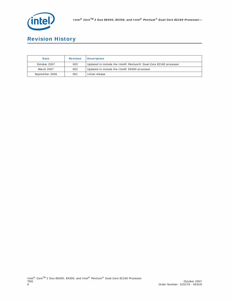
Revision History
Date Revision Description
October 2007 003 Updated to include the Intel® Pentium® Dual-Core E2160 processor
March 2007 002 Updated to include the Intel® E4300 processor
September 2006 001 Initial release
Intel® CoreTM 2 Duo E6400, E4300, and Intel® Pentium® Dual-Core E2160 ProcessorOctober 2007 TDGOrder Number: 315279 - 003US 7
Introduction—Intel® CoreTM 2 Duo E6400, E4300, and Intel® Pentium® Dual-Core E2160 Processor
1.0 Introduction
1.1 Document Goals and Scope
1.1.1 Importance of Thermal Management
The objective of thermal management is to ensure that the temperatures of all components in a system are maintained within their functional temperature range. Within this range, a component is expected to meet its specified performance level. Operation outside the functional temperature range can degrade system performance, cause logic errors or cause component and/or system damage. Temperatures exceeding the maximum operating limit of a component may result in irreversible changes in the operating characteristics of this component.
In a system environment, the processor temperature is a function of both system and component thermal characteristics. The system level thermal constraints consist of the local ambient air temperature and airflow over the processor as well as the physical constraints at and above the processor. The processor temperature depends on the component power dissipation, the processor package thermal characteristics and the processor thermal solution.
All of these parameters are affected by the continued push of technology to increase processor performance levels and packaging density (more transistors). As operating frequencies increase and packaging size decreases, the power density increases while the thermal solution space and airflow typically become more constrained or remains the same within the system. The result is an increased importance on system design to ensure that thermal design requirements are met for each component, including the processor, in the system.
1.1.2 Document Goals
Depending on the type of system and the chassis characteristics, new system and component designs may be required to provide adequate cooling for the processor. The goal of this document is to provide an understanding of these thermal characteristics and discuss guidelines for meeting the thermal requirements imposed on single processor systems using the Intel® CoreTM 2 Duo E6400, E4300, and Intel® Pentium® Dual-Core E2160 Processor.
The concepts given in this document are applicable to any system form factor. Specific examples used will be the Intel enabled reference solution for PICMG 1.3 server systems. Please refer to the applicable ATX and BTX form factor reference documents and thermal design guidelines to design a thermal solution for those form factors.
1.1.3 Document Scope
In this document, when a reference is made to "the processor", it is intended that this includes all the processors described and supported in this document. If needed for clarity, the specific processor will be listed.
Intel® CoreTM 2 Duo E6400, E4300, and Intel® Pentium® Dual-Core E2160 Processor—Introduction
Intel® CoreTM 2 Duo E6400, E4300, and Intel® Pentium® Dual-Core E2160 ProcessorTDG October 20078 Order Number: 315279 - 003US
This design guide supports the following processors:
• Intel® CoreTM 2 Duo E6400 Processor for Embedded Applications
• Intel® CoreTM 2 Duo E4300 Processor for Embedded Applications
• Intel® Pentium® Dual-Core E2160 Processor for Embedded Applications
In this document, when a reference is made to "the datasheet", the reader should refer to the Intel® Core™2 Extreme Processor X6800 and Intel® Core™2 Duo Desktop Processor E6000 and E4000 Sequences Datasheet and Intel® Pentium® Dual-Core Processor E2000 Sequence Datasheet. For more information on a specific processor, reference the specific processor datasheet.
Section 2.0 of this document discusses package thermal mechanical requirements to design a thermal solution for the processor in the context of personal computer applications.
Section 2.0 discusses the thermal solution considerations and metrology recommendations to validate a processor thermal solution.
Section 4.0 addresses the benefits of the processor's integrated thermal management logic for thermal design.
Section 5.0 gives information on the Intel reference thermal solution for the processor.
Section 6.0 discusses the implementation of Intel Quiet System Technology (Intel® QST).
The physical dimensions and thermal specifications of the processor that are used in this document are for illustration only. Refer to the datasheet for the product dimensions, thermal power dissipation and maximum case temperature. In case of conflict, the data in the datasheet supersedes any data in this document.

Intel® CoreTM 2 Duo E6400, E4300, and Intel® Pentium® Dual-Core E2160 ProcessorOctober 2007 TDGOrder Number: 315279 - 003US 9
Introduction—Intel® CoreTM 2 Duo E6400, E4300, and Intel® Pentium® Dual-Core E2160 Processor
1.2 References
Material and concepts available in the documents listed in Table 1 may be beneficial when reading this document.
1.3 Definition of Terms
Table 1. Referenced Documents
Document Comment
Intel® Core™2 Duo Desktop Processor, Intel® Pentium® Dual-Core Processor, and Intel® Pentium® 4 Processor 6x1 Sequence Thermal and Mechanical Design Guidelines
http://developer.intel.com/design/processor/designex/313685.htm
LGA775 Socket Mechanical Design Guidehttp://developer.intel.com/design/Pentium4/guides/302666.htm
Intel® Core™2 Extreme Processor X6800 and Intel® Core™2 Duo Desktop Processor E6000 Sequence Datasheet
http://www.intel.com/design/processor/datashts/313278.htm
Intel® Pentium® Dual-Core Processor E2000 Sequence Datasheet http://www.intel.com/design/processor/datashts/316981.htm
Intel® Core™2 Processor and Intel® Pentium® Dual Core Processor Thermal and Mechanical Design Guidelines
http://www.intel.com/design/processor/designex/317804.htm
Intel® Pentium® 4 Processor on 90 nm Process in the 775-Land LGA Package Thermal and Mechanical Design Guidelines
http://developer.intel.com/design/Pentium4/guides/302553.htm
Fan Specification for 4-wire PWM Controlled Fans http://www.formfactors.org/
Performance ATX Desktop System Thermal Design Suggestions http://www.formfactors.org/
Performance microATX Desktop System Thermal Design Suggestions http://www.formfactors.org/
Balanced Technology Extended (BTX) System Design Guide http://www.formfactors.org/
Table 2. Terms Used (Sheet 1 of 2)
Term Description
TA
The measured ambient temperature locally surrounding the processor. The ambient temperature should be measured just upstream of a passive heatsink or at the fan inlet for an active heatsink. Also referred to as TLA.
TCThe case temperature of the processor, measured at the geometric center of the topside of the IHS.
TEThe ambient air temperature external to a system chassis. This temperature is usually measured at the chassis air inlets. Also referred to as TEXT.
TSHeatsink temperature measured on the underside of the heatsink base, at a location corresponding to TC.
TC-MAX The maximum case temperature as specified in a component specification.
ΨCA
Case-to-ambient thermal characterization parameter (psi). A measure of thermal solution performance using total package power. Defined as (TC - TA) / Total Package Power.Note: Heat source must be specified for Ψ measurements.
ΨCS
Case-to-sink thermal characterization parameter. A measure of thermal interface material performance using total package power. Defined as (TC - TS) / Total Package Power. Also referred to as ΨTIM.Note: Heat source must be specified for Ψ measurements.

Intel® CoreTM 2 Duo E6400, E4300, and Intel® Pentium® Dual-Core E2160 Processor—Introduction
Intel® CoreTM 2 Duo E6400, E4300, and Intel® Pentium® Dual-Core E2160 ProcessorTDG October 200710 Order Number: 315279 - 003US
§ §
ΨSA
Sink-to-ambient thermal characterization parameter. A measure of heatsink thermal performance using total package power. Defined as (TS - TA) / Total Package Power.Note: Heat source must be specified for Ψ measurements.
TIMThermal Interface Material: The thermally conductive compound between the heatsink and the processor case. This material fills the air gaps and voids, and enhances the transfer of the heat from the processor case to the heatsink.
PMAX The maximum power dissipated by a semiconductor component.
TDP Thermal Design Power: a power dissipation target based on worst-case applications. Thermal solutions should be designed to dissipate the thermal design power.
IHS Integrated Heat Spreader: a thermally conductive lid integrated into a processor package to improve heat transfer to a thermal solution through heat spreading.
LGA775 Socket The surface mount socket designed to accept the processors in the 775-Land LGA package.
ACPI Advanced Configuration and Power Interface.
BypassBypass is the area between a passive heatsink and any object that can act to form a duct. For this example, it can be expressed as a dimension away from the outside dimension of the fins to the nearest surface.
Thermal Monitor A feature on the processor that attempts to keep the processor die temperature within factory specifications.
TCCThermal Control Circuit: Thermal Monitor uses the TCC to reduce die temperature by lowering effective processor frequency when the die temperature has exceeded its operating limits.
TDIODE Temperature reported from the on-die thermal diode.
FSCFan Speed Control: Thermal solution that includes a variable fan speed which is driven by a PWM signal and uses the on-die thermal diode as a reference to change the duty cycle of the PWM signal.
TCONTROL TCONTROL is the specification limit for use with the on-die thermal diode.
PWMPulse width modulation is a method of controlling a variable speed fan. The enabled 4 wire fans use the PWM duty cycle percent from the fan speed controller to modulate the fan speed.
Health Monitor Component
Any standalone or integrated component that is capable of reading the processor temperature and providing the PWM signal to the 4 pin fan header.
TMA Thermal Module Assembly. The heatsink, fan and duct assembly for the BTX thermal solution.
Table 2. Terms Used (Sheet 2 of 2)
Term Description

Intel® CoreTM 2 Duo E6400, E4300, and Intel® Pentium® Dual-Core E2160 ProcessorOctober 2007 TDGOrder Number: 315279 -003US 11
Processor Thermal/Mechanical Information—Intel® CoreTM 2 Duo E6400, E4300, and Intel® Pentium® Dual-Core E2160 Processor
2.0 Processor Thermal/Mechanical Information
2.1 Mechanical Requirements
2.1.1 Processor Package
The processor is packaged in a 775-Land LGA package that interfaces with the motherboard via a LGA775 socket. Refer to the datasheet for detailed mechanical specifications.
The processor connects to the motherboard through a land grid array (LGA) surface mount socket. The socket contains 775 contacts arrayed about a cavity in the center of the socket with solder balls for surface mounting to the motherboard. The socket is named LGA775 socket. A description of the socket can be found in the LGA775 Socket Mechanical Design Guide.
The package includes an integrated heat spreader (IHS) that is shown in Figure 1. Refer to the processor datasheet for more information. In case of conflict, the package dimensions in the processor datasheet supersedes dimensions provided in this document.
Figure 1. Package IHS Load Areas
Top Su rface o f IHS to in s ta ll a h e ats in k
IHS Ste p to in te rface w ith LGA775
Socke t Load P lateSu bstrate Top Su rface o f IHS
to in s ta ll a h e ats in k
IHS Ste p to in te rface w ith LGA775
Socke t Load P lateSu bstrate
Intel® CoreTM 2 Duo E6400, E4300, and Intel® Pentium® Dual-Core E2160 Processor—ProcessorThermal/Mechanical Information
Intel® CoreTM 2 Duo E6400, E4300, and Intel® Pentium® Dual-Core E2160 ProcessorTDG October 200712 Order Number: 315279 -003US
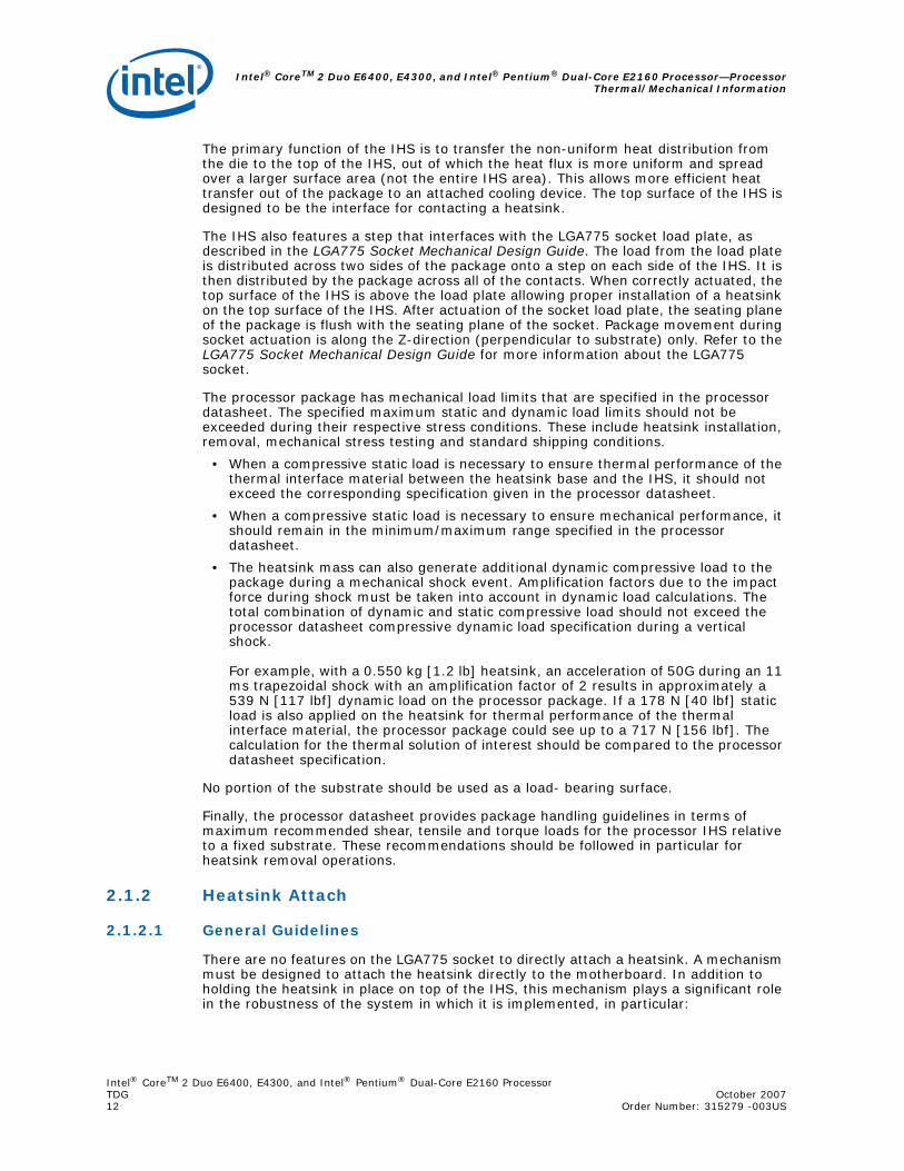
The primary function of the IHS is to transfer the non-uniform heat distribution from the die to the top of the IHS, out of which the heat flux is more uniform and spread over a larger surface area (not the entire IHS area). This allows more efficient heat transfer out of the package to an attached cooling device. The top surface of the IHS is designed to be the interface for contacting a heatsink.
The IHS also features a step that interfaces with the LGA775 socket load plate, as described in the LGA775 Socket Mechanical Design Guide. The load from the load plate is distributed across two sides of the package onto a step on each side of the IHS. It is then distributed by the package across all of the contacts. When correctly actuated, the top surface of the IHS is above the load plate allowing proper installation of a heatsink on the top surface of the IHS. After actuation of the socket load plate, the seating plane of the package is flush with the seating plane of the socket. Package movement during socket actuation is along the Z-direction (perpendicular to substrate) only. Refer to the LGA775 Socket Mechanical Design Guide for more information about the LGA775 socket.
The processor package has mechanical load limits that are specified in the processor datasheet. The specified maximum static and dynamic load limits should not be exceeded during their respective stress conditions. These include heatsink installation, removal, mechanical stress testing and standard shipping conditions.
• When a compressive static load is necessary to ensure thermal performance of the thermal interface material between the heatsink base and the IHS, it should not exceed the corresponding specification given in the processor datasheet.
• When a compressive static load is necessary to ensure mechanical performance, it should remain in the minimum/maximum range specified in the processor datasheet.
• The heatsink mass can also generate additional dynamic compressive load to the package during a mechanical shock event. Amplification factors due to the impact force during shock must be taken into account in dynamic load calculations. The total combination of dynamic and static compressive load should not exceed the processor datasheet compressive dynamic load specification during a vertical shock.
For example, with a 0.550 kg [1.2 lb] heatsink, an acceleration of 50G during an 11 ms trapezoidal shock with an amplification factor of 2 results in approximately a 539 N [117 lbf] dynamic load on the processor package. If a 178 N [40 lbf] static load is also applied on the heatsink for thermal performance of the thermal interface material, the processor package could see up to a 717 N [156 lbf]. The calculation for the thermal solution of interest should be compared to the processor datasheet specification.
No portion of the substrate should be used as a load- bearing surface.
Finally, the processor datasheet provides package handling guidelines in terms of maximum recommended shear, tensile and torque loads for the processor IHS relative to a fixed substrate. These recommendations should be followed in particular for heatsink removal operations.
2.1.2 Heatsink Attach
2.1.2.1 General Guidelines
There are no features on the LGA775 socket to directly attach a heatsink. A mechanism must be designed to attach the heatsink directly to the motherboard. In addition to holding the heatsink in place on top of the IHS, this mechanism plays a significant role in the robustness of the system in which it is implemented, in particular:
Intel® CoreTM 2 Duo E6400, E4300, and Intel® Pentium® Dual-Core E2160 ProcessorOctober 2007 TDGOrder Number: 315279 -003US 13
Processor Thermal/Mechanical Information—Intel® CoreTM 2 Duo E6400, E4300, and Intel® Pentium® Dual-Core E2160 Processor
• Ensuring thermal performance of the thermal interface material (TIM) applied between the IHS and the heatsink. TIMs based on phase change materials are very sensitive to applied pressure: the higher the pressure, the better the initial performance. TIMs, such as thermal greases, are not as sensitive to applied pressure. Designs should consider a possible decrease in applied pressure over time due to potential structural relaxation in retention components.
• Ensuring system electrical, thermal and structural integrity under shock and vibration events. The mechanical requirements of the heatsink attach mechanism depend on the mass of the heatsink and the level of shock and vibration that the system must support. The overall structural design of the motherboard and the system have to be considered when designing the heatsink attach mechanism. Their design should provide a means for protecting LGA775 socket solder joints. One of the strategies for mechanical protection of the socket is to use a preload and high stiffness clip. This strategy is implemented by the reference design and described in this document.
Note: Package pull-out during mechanical shock and vibration is constrained by the LGA775 socket load plate (refer to the LGA775 Socket Mechanical Design Guide for more information).
2.1.2.2 Heatsink Clip Load Requirement
The attach mechanism for the heatsink developed to support the processor should create a static preload on the package between 18 lbf and 70 lbf throughout the life of the product for designs compliant with the Intel reference design assumption:
• 72 mm x 72 mm mounting hole span (refer to Figure 20)
The minimum load is required to protect against fatigue failure of socket solder joint in temperature cycling.
It is important to take into account potential load degradation from creep over time when designing the clip and fastener to the required minimum load. This means that, depending on clip stiffness, the initial preload at beginning of life of the product may be significantly higher than the minimum preload that must be met throughout the life of the product. For additional guidelines on mechanical design, in particular on designs departing from the reference design assumptions, refer to Appendix A.
For information on Clip loading, refer to the Intel® Core™2 Duo Desktop Processor E6000? Sequence Thermal and Mechanical Design Guidelines Supporting the Intel® Core™2 Duo desktop processor E6000 Sequence.
2.1.2.3 Additional Guidelines
In addition to the general guidelines given above, the heatsink attach mechanism for the processor should be designed to the following guidelines:
• Holds the heatsink in place under mechanical shock and vibration events and applies force to the heatsink base to maintain desired pressure on the thermal interface material. Note that the load applied by the heatsink attach mechanism must comply with the package specifications described in the processor datasheet. One of the key design parameters is the height of the top surface of the processor IHS above the motherboard. The IHS height from the top of board is expected to vary from 7.517 mm to 8.167 mm. This data is provided for information only, and should be derived from:
— The height of the socket seating plane above the motherboard after reflow, given in the LGA775 Socket Mechanical Design Guide with its tolerances.
Intel® CoreTM 2 Duo E6400, E4300, and Intel® Pentium® Dual-Core E2160 Processor—ProcessorThermal/Mechanical Information
Intel® CoreTM 2 Duo E6400, E4300, and Intel® Pentium® Dual-Core E2160 ProcessorTDG October 200714 Order Number: 315279 -003US
— The height of the package, from the package seating plane to the top of the IHS, and accounting for its nominal variation and tolerances that are given in the corresponding processor datasheet.
• Engages easily, and if possible, without the use of special tools. In general, the heatsink is assumed to be installed after the motherboard has been installed into the chassis.
• Minimizes contact with the motherboard surface during installation and actuation to avoid scratching the motherboard.
2.2 Thermal Requirements
Refer to the datasheet for the processor thermal specifications. The majority of processor power is dissipated through the IHS. There are no additional components, e.g., BSRAMs, which generate heat on this package. The amount of power that can be dissipated as heat through the processor package substrate and into the socket is usually minimal.
The thermal limits for the processor are the Thermal Profile and TCONTROL. The Thermal Profile defines the maximum case temperature as a function of power being dissipated. TCONTROL is a specification used in conjunction with the temperature reported by the on-die thermal diode and a fan speed control method. Designing to these specifications allows optimization of thermal designs for processor performance and acoustic noise reduction.
2.2.1 Processor Case Temperature
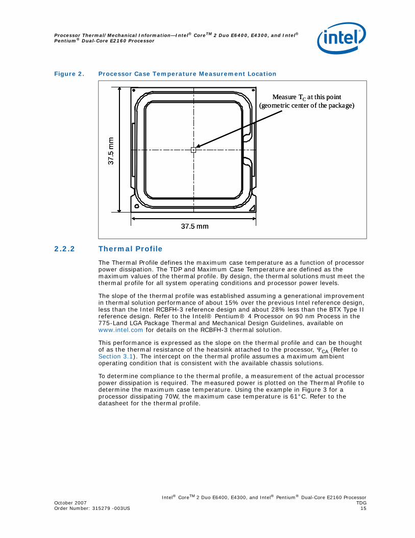
For the processor, the case temperature is defined as the temperature measured at the geometric center of the package on the surface of the IHS. For illustration, Figure 2 shows the measurement location for a 37.5 mm x 37.5 mm [1.474 in x 1.474 in] 775-Land LGA processor package with a 28.7 mm x 28.7 mm [1.13 in x 1.13 in] IHS top surface. Techniques for measuring the case temperature are detailed in Section 3.4.
Note: In case of conflict, the package dimensions in the processor datasheet supersedes dimensions provided in this document.
Intel® CoreTM 2 Duo E6400, E4300, and Intel® Pentium® Dual-Core E2160 ProcessorOctober 2007 TDGOrder Number: 315279 -003US 15
Processor Thermal/Mechanical Information—Intel® CoreTM 2 Duo E6400, E4300, and Intel® Pentium® Dual-Core E2160 Processor
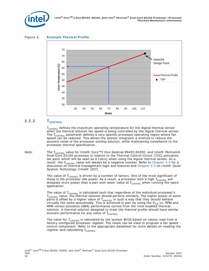
2.2.2 Thermal Profile
The Thermal Profile defines the maximum case temperature as a function of processor power dissipation. The TDP and Maximum Case Temperature are defined as the maximum values of the thermal profile. By design, the thermal solutions must meet the thermal profile for all system operating conditions and processor power levels.
The slope of the thermal profile was established assuming a generational improvement in thermal solution performance of about 15% over the previous Intel reference design, less than the Intel RCBFH-3 reference design and about 28% less than the BTX Type II reference design. Refer to the Intel® Pentium® 4 Processor on 90 nm Process in the 775-Land LGA Package Thermal and Mechanical Design Guidelines, available on www.intel.com for details on the RCBFH-3 thermal solution.
This performance is expressed as the slope on the thermal profile and can be thought of as the thermal resistance of the heatsink attached to the processor, ΨCA (Refer to Section 3.1). The intercept on the thermal profile assumes a maximum ambient operating condition that is consistent with the available chassis solutions.
To determine compliance to the thermal profile, a measurement of the actual processor power dissipation is required. The measured power is plotted on the Thermal Profile to determine the maximum case temperature. Using the example in Figure 3 for a processor dissipating 70W, the maximum case temperature is 61°C. Refer to the datasheet for the thermal profile.
Figure 2. Processor Case Temperature Measurement Location
37.5 mm
Measure TC at this point (geometric center of the package)
37.5
mm
37.5 mm
Measure TC at this point (geometric center of the package)
37.5
mm
Intel® CoreTM 2 Duo E6400, E4300, and Intel® Pentium® Dual-Core E2160 Processor—ProcessorThermal/Mechanical Information
Intel® CoreTM 2 Duo E6400, E4300, and Intel® Pentium® Dual-Core E2160 ProcessorTDG October 200716 Order Number: 315279 -003US
2.2.3 TCONTROL
TCONTROL defines the maximum operating temperature for the digital thermal sensor when the thermal solution fan speed is being controlled by the digital thermal sensor. The TCONTROL parameter defines a very specific processor operating region where fan speed can be reduced. This allows the system integrator a method to reduce the acoustic noise of the processor cooling solution, while maintaining compliance to the processor thermal specification.
Note: The TCONTROL value for Intel® Core™2 Duo desktop E6400,E4300, and Intel® Pentium® Dual-Core E2160 processor is relative to the Thermal Control Circuit (TCC) activation set point which will be seen as 0 (zero) when using the digital thermal sensor. As a result, the TCONTROL value will always be a negative number. Refer to Chapter 4.0 for a discussion on thermal management logic and features and Chapter 6.0 on Intel® Quiet System Technology (Intel® QST).
The value of TCONTROL is driven by a number of factors. One of the most significant of these is the processor idle power. As a result, a processor with a high TCONTROL will dissipate more power than a part with lower value of TCONTROL when running the same application.
The value of TCONTROL is calculated such that regardless of the individual processor's TCONTROL value, the thermal solution should perform similarly. The higher power of some parts is offset by a higher value of TCONTROL in such a way that they should behave virtually the same acoustically. This is achieved in part by using the ΨCA vs. RPM and RPM versus acoustics (dBA) performance curves from the Intel enabled thermal solution. A thermal solution designed to meet the thermal profile should have similar acoustic performance for any value of TCONTROL.
The value for TCONTROL is calculated by the system BIOS based on values read from a factory configured processor register. The result can be used to program a fan speed control component. Refer to the appropriate datasheet for more details on reading the register and calculating TCONTROL.
Figure 3. Example Thermal Profile
30
35
40
45
50
55
60
65
70
75
30 40 50 60 70 80 90 100 110
Watts
Cas
e Te
mpe
ratu
re (C
)
Thermal Profile
TDP
Heatsink Design Point

Intel® CoreTM 2 Duo E6400, E4300, and Intel® Pentium® Dual-Core E2160 ProcessorOctober 2007 TDGOrder Number: 315279 -003US 17
Processor Thermal/Mechanical Information—Intel® CoreTM 2 Duo E6400, E4300, and Intel® Pentium® Dual-Core E2160 Processor
Refer to Chapter 6.0, Intel® Quiet System Technology (Intel® QST), for details on implementing a design using TCONTROL and the Thermal Profile.
2.3 Heatsink Design Considerations
To remove the heat from the processor, three basic parameters should be considered:
• The surface area on which the heat transfer takes place. Without any enhancements, this is the surface of the processor package IHS. One method used to improve thermal performance is by attaching a heatsink to the IHS. A heatsink can increase the effective heat transfer surface area by conducting heat out of the IHS and into the surrounding air through fins attached to the heatsink base.
• The conduction path from the heat source to the heatsink fins. Providing a direct conduction path from the heat source to the heatsink fins and selecting materials with higher thermal conductivity typically improves heatsink performance. The length, thickness, and conductivity of the conduction path from the heat source to the fins directly impact the thermal performance of the heatsink. In particular, the quality of the contact between the package IHS and the heatsink base has a higher impact on the overall thermal solution performance as processor cooling requirements become stricter. Thermal interface material (TIM) is used to fill in the gap between the IHS and the bottom surface of the heatsink, and thereby, improve the overall performance of the stack-up (IHS-TIM-Heatsink). With extremely poor heatsink interface flatness or roughness, TIM may not adequately fill the gap. The TIM thermal performance depends on its thermal conductivity as well as the pressure applied to it. Refer to Section 2.3.4 and Appendix B for more information on TIM and on bond line management between the IHS and the heatsink base.
• The heat transfer conditions on the surface on which heat transfer takes place. Convective heat transfer occurs between the airflow and the surface exposed to the flow. It is characterized by the local ambient temperature of the air, TA and the local air velocity over the surface. The higher the air velocity over the surface, and the cooler the air, the more efficient is the resulting cooling. The nature of the airflow can also enhance heat transfer via convection. Turbulent flow can provide improvement over laminar flow. In the case of a heatsink, the surface exposed to the flow includes in particular the fin faces and the heatsink base.
Active heatsinks typically incorporate a fan that helps manage the airflow through the heatsink.
Passive heatsink solutions require in-depth knowledge of the airflow in the chassis. Typically, passive heatsinks see lower air speed. These heatsinks are therefore typically larger (and heavier) than active heatsinks due to the increase in fin surface required to meet a required performance. As the heatsink fin density (the number of fins in a given cross-section) increases, the resistance to the airflow increases, and it is more likely that the air travels around the heatsink instead of through it, unless air bypass is carefully managed. Using air-ducting techniques to manage the bypass area can be an effective method for controlling airflow through the heatsink.
2.3.1 Heatsink Size
The size of the heatsink is dictated by height restrictions for installation in a system and by the real estate available on the motherboard and other considerations for component height and placement in the area potentially impacted by the processor heatsink. The height of the heatsink must comply with the requirements and recommendations published for the motherboard form factor of interest. Designing a heatsink to the recommendations may preclude using it in system adhering strictly to the form factor requirements, while still in compliance with the form factor documentation.
Intel® CoreTM 2 Duo E6400, E4300, and Intel® Pentium® Dual-Core E2160 Processor—ProcessorThermal/Mechanical Information
Intel® CoreTM 2 Duo E6400, E4300, and Intel® Pentium® Dual-Core E2160 ProcessorTDG October 200718 Order Number: 315279 -003US
For the PICMG 1.3 server form factor, it is recommended to use:
• The PICMG 1.3 motherboard keep-out footprint definition and height restrictions for enabling components, defined for the platforms designed with the LGA775 socket in Appendix E of this design guide.
• The motherboard primary side height constraints are located at http://picmg.org/specifications.stm.
The resulting space available above the motherboard is generally not entirely available for the heatsink. The target height of the heatsink must take into account airflow considerations (for fan performance for example) as well as other design considerations (air duct, etc.).
2.3.2 Heatsink Mass
With the need to push air cooling to better performance, heatsink solutions tend to grow larger (increase in fin surface) resulting in increased mass. The insertion of highly thermally conductive materials like copper to increase heatsink thermal conduction performance results in even heavier solutions. As mentioned in Section 2.1, the heatsink mass must take into consideration the package and socket load limits, the heatsink attach mechanical capabilities and the mechanical shock and vibration profile targets. Beyond a certain heatsink mass, the cost of developing and implementing a heatsink attach mechanism that can ensure the system integrity under the mechanical shock and vibration profile targets may become prohibitive.
2.3.3 Package IHS Flatness
The package IHS flatness for the product is specified in the datasheet and can be used as a baseline to predict heatsink performance during the design phase.
Intel recommends testing and validating heatsink performance in full mechanical enabling configuration to capture any impact of IHS flatness change due to combined socket and heatsink loading. While socket loading alone may increase the IHS warpage, the heatsink preload redistributes the load on the package and improves the resulting IHS flatness in the enabled state.
2.3.4 Thermal Interface Material
Thermal interface material application between the processor IHS and the heatsink base is required to improve thermal conduction from the IHS to the heatsink. Many thermal interface materials can be pre-applied to the heatsink base prior to shipment from the heatsink supplier and allow direct heatsink attach, without the need for a separate thermal interface material dispense or attach process in the final assembly factory.
All thermal interface materials should be sized and positioned on the heatsink base in a way that ensures the entire processor IHS area is covered. It is important to compensate for heatsink-to-processor attach positional alignment when selecting the proper thermal interface material size.
When pre-applied material is used, it is recommended to have a protective application tape over it. This tape must be removed prior to heatsink installation.
Intel® CoreTM 2 Duo E6400, E4300, and Intel® Pentium® Dual-Core E2160 ProcessorOctober 2007 TDGOrder Number: 315279 -003US 19
Processor Thermal/Mechanical Information—Intel® CoreTM 2 Duo E6400, E4300, and Intel® Pentium® Dual-Core E2160 Processor
2.4 System Thermal Solution Considerations
2.4.1 Chassis Thermal Design Capabilities
The Intel reference thermal solution for PICMG 1.3 chassis assumes that the chassis delivers a maximum TA of 38-40°C with 15-25 CFM of airflow at the inlet of the processor heatsink.
2.4.2 Improving Chassis Thermal Performance
The heat generated by components within the chassis must be removed to provide an adequate operating environment for both the processor and other system components. Moving air through the chassis brings in air from the external ambient environment and transports the heat generated by the processor and other system components out of the system. The number, size and relative position of fans and vents determine the chassis thermal performance, and the resulting ambient temperature around the processor. The size and type (passive or active) of the thermal solution and the amount of system airflow can be traded off against each other to meet specific system design constraints. Additional constraints are board layout, spacing, component placement, acoustic requirements and structural considerations that limit the thermal solution size. For more information, refer to the Thin Electronics Bay specification at the following web site: www.ssiforum.org.
In addition to passive heatsinks, fan heatsinks and system fans are other solutions that exist for cooling integrated circuit devices. For example, ducted blowers, heat pipes and liquid cooling are all capable of dissipating additional heat. Due to their varying attributes, each of these solutions may be appropriate for a particular system implementation.
To develop a reliable, cost-effective thermal solution, thermal characterization and simulation should be carried out at the entire system level, accounting for the thermal requirements of each component. In addition, acoustic noise constraints may limit the size, number, placement and types of fans that can be used in a particular design.
To ease the burden on thermal solutions, the Thermal Monitor feature and associated logic have been integrated into the silicon of the processor. By taking advantage of the Thermal Monitor feature, system designers may reduce the thermal solution cost by designing to TDP instead of maximum power. Thermal Monitor attempts to protect the processor during sustained workload above TDP. Implementation options and recommendations are described in Section 4.
2.4.3 Summary
In summary, considerations in heatsink design include:
• The local ambient temperature TA at the heatsink, which is a function of chassis design.
• The thermal design power (TDP) of the processor, and the corresponding maximum TC as calculated from the thermal profile. These parameters are usually combined in a single lump cooling performance parameter, ΨCA (case to air thermal characterization parameter). More information on the definition and the use of ΨCA is given in section 3.1.
• Heatsink interface to IHS surface characteristics, including flatness and roughness.
• The performance of the thermal interface material used between the heatsink and the IHS.
• The required heatsink clip static load, between 18 lbf to 70 lbf throughout the life of the product (Refer to Section 2.1.2.2 for more information).
Intel® CoreTM 2 Duo E6400, E4300, and Intel® Pentium® Dual-Core E2160 Processor—ProcessorThermal/Mechanical Information
Intel® CoreTM 2 Duo E6400, E4300, and Intel® Pentium® Dual-Core E2160 ProcessorTDG October 200720 Order Number: 315279 -003US
• Surface area of the heatsink.
• Heatsink material and technology.
• Volume of airflow over the heatsink surface area.
• Development of airflow entering and within the heatsink area.
• Physical volumetric constraints placed by the system.
2.5 System Integration Considerations
Manufacturing with Intel® Components using 775-Land LGA Package and LGA775 Socket documentation provides Best Known Methods for all aspects of LGA775 socket based platforms and systems manufacturing. Of particular interest for package and heatsink installation and removal is the System Assembly module. A video covering system integration is also available. Contact your Intel field sales representative for more information.
Intel® CoreTM 2 Duo E6400, E4300, and Intel® Pentium® Dual-Core E2160 ProcessorOctober 2007 TDGOrder Number: 315279 - 003US 21
Thermal Metrology—Intel® CoreTM 2 Duo E6400, E4300, and Intel® Pentium® Dual-Core E2160 Processor
3.0 Thermal Metrology
This section discusses guidelines for testing thermal solutions, including measuring processor temperatures. In all cases, the thermal engineer must measure power dissipation and temperature to validate a thermal solution. To define the performance of a thermal solution the "thermal characterization parameter", Ψ ("psi") will be used.
3.1 Characterizing Cooling Performance Requirements
The idea of a "thermal characterization parameter", Ψ ("psi"), is a convenient way to characterize the performance needed for the thermal solution and to compare thermal solutions in identical situations (same heat source and local ambient conditions). The thermal characterization parameter is calculated using total package power.
Note: Heat transfer is a three-dimensional phenomenon that can rarely be accurately and easily modeled by a single resistance parameter like Ψ.
The case-to-local ambient thermal characterization parameter value (ΨCA) is used as a measure of the thermal performance of the overall thermal solution that is attached to the processor package. It is defined by the following equation, and measured in units of °C/W:
Equation 1. ΨCA = (TC - TA) / PD
Where:
ΨCA = Case-to-local ambient thermal characterization parameter (°C/W)
TC = Processor case temperature (°C)
TA = Local ambient temperature in chassis at processor (°C)
PD = Processor total power dissipation (W) (assumes all power dissipatesthrough the IHS)
The case-to-local ambient thermal characterization parameter of the processor, ΨCA, is comprised of ΨCS, the thermal interface material thermal characterization parameter, and of ΨSA, the sink-to-local ambient thermal characterization parameter:
Equation 2. ΨCA = ΨCS + ΨSA
Where:
ΨCS = Thermal characterization parameter of the thermal interface material (°C/W)
ΨSA = Thermal characterization parameter from heatsink-to-local ambient (°C/W)
ΨCS is strongly dependent on the thermal conductivity and thickness of the TIM between the heatsink and IHS.
Intel® CoreTM 2 Duo E6400, E4300, and Intel® Pentium® Dual-Core E2160 Processor—ThermalMetrology
Intel® CoreTM 2 Duo E6400, E4300, and Intel® Pentium® Dual-Core E2160 ProcessorTDG October 200722 Order Number: 315279 - 003US
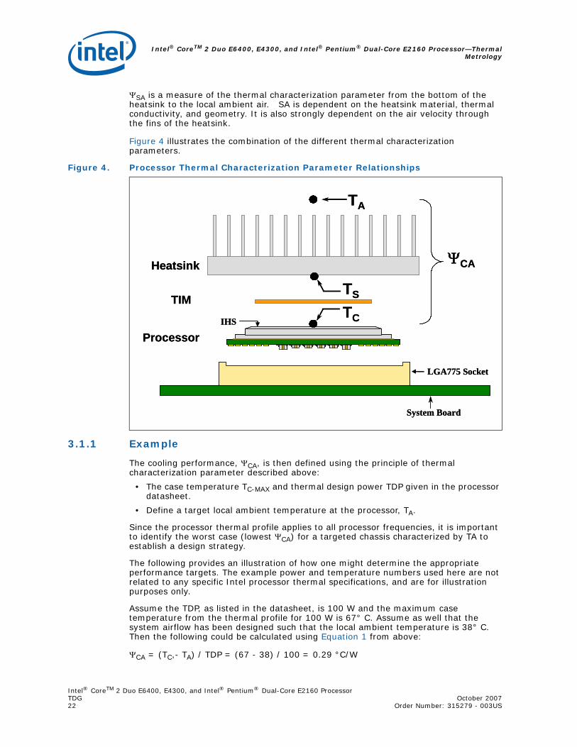
ΨSA is a measure of the thermal characterization parameter from the bottom of the heatsink to the local ambient air. SA is dependent on the heatsink material, thermal conductivity, and geometry. It is also strongly dependent on the air velocity through the fins of the heatsink.
Figure 4 illustrates the combination of the different thermal characterization parameters.
3.1.1 Example
The cooling performance, ΨCA, is then defined using the principle of thermal characterization parameter described above:
• The case temperature TC-MAX and thermal design power TDP given in the processor datasheet.
• Define a target local ambient temperature at the processor, TA.
Since the processor thermal profile applies to all processor frequencies, it is important to identify the worst case (lowest ΨCA) for a targeted chassis characterized by TA to establish a design strategy.
The following provides an illustration of how one might determine the appropriate performance targets. The example power and temperature numbers used here are not related to any specific Intel processor thermal specifications, and are for illustration purposes only.
Assume the TDP, as listed in the datasheet, is 100 W and the maximum case temperature from the thermal profile for 100 W is 67° C. Assume as well that the system airflow has been designed such that the local ambient temperature is 38° C. Then the following could be calculated using Equation 1 from above:
ΨCA = (TC,- TA) / TDP = (67 - 38) / 100 = 0.29 °C/W
Figure 4. Processor Thermal Characterization Parameter Relationships
TIMTS
TA
ΨCA
LGA775 Socket
ProcessorIHS
System Board
TC
Heatsink
TIMTS
TA
ΨCA
LGA775 Socket
ProcessorIHS
System Board
TC
Heatsink

Intel® CoreTM 2 Duo E6400, E4300, and Intel® Pentium® Dual-Core E2160 ProcessorOctober 2007 TDGOrder Number: 315279 - 003US 23
Thermal Metrology—Intel® CoreTM 2 Duo E6400, E4300, and Intel® Pentium® Dual-Core E2160 Processor
To determine the required heatsink performance, a heatsink solution provider would need to determine CS performance for the selected TIM and mechanical load configuration. If the heatsink solution were designed to work with a TIM material performing at CS 0.10 °C/W, solving for Equation 2 from above, the performance of the heatsink would be:
ΨSA = ΨCA - ΨCS = 0.29 - 0.10 = 0.19 °C/W
3.2 Processor Thermal Solution Performance Assessment
Thermal performance of a heatsink should be assessed using a thermal test vehicle (TTV) provided by Intel. The TTV is a stable heat source for making accurate power measurements, whereas processors can introduce additional factors that can impact test results. In particular, the power level from actual processors varies significantly, even when running the maximum power application provided by Intel, due to variances in the manufacturing process. The TTV provides consistent power and power density for thermal solution characterization and results can be easily translated to real processor performance. Accurate measurement of the power dissipated by an actual processor is beyond the scope of this document.
Once the thermal solution is designed and validated with the TTV, it is strongly recommended to verify functionality of the thermal solution on real processors and on fully integrated systems The Intel maximum power application enables steady power dissipation on a processor to assist in this testing. This application is called the Maximum Power Program for the Intel® Core™ 2 Duo Processor. Contact your Intel Field Sales representative for a copy of the latest release of this application.
3.3 Local Ambient Temperature Measurement Guidelines
The local ambient temperature TA is the temperature of the ambient air surrounding the processor. For a passive heatsink, TA is defined as the heatsink approach air temperature; for an actively cooled heatsink, it is the temperature of inlet air to the active cooling fan.
It is worthwhile to determine the local ambient temperature in the chassis around the processor to understand the effect it may have on the case temperature.
TA is best measured by averaging temperature measurements at multiple locations in the heatsink inlet airflow. This method helps reduce error and eliminate minor spatial variations in temperature. The following guidelines are meant to enable accurate determination of the localized air temperature around the processor during system thermal testing.
For active heatsinks, it is important to avoid taking a measurement in the dead flow zone that usually develops above the fan hub and hub spokes. Measurements should be taken at four different locations uniformly placed at the center of the annulus formed by the fan hub and the fan housing to evaluate the uniformity of the air temperature at the fan inlet. The thermocouples should be placed approximately 3 mm to 8 mm [0.1 to 0.3 in] above the fan hub vertically and halfway between the fan hub and the fan housing horizontally as shown in Figure 5 (avoiding the hub spokes). Using an open bench to characterize an active heatsink can be useful, and usually ensures more uniform temperatures at the fan inlet. However, additional tests that include a solid barrier above the test motherboard surface can help evaluate the potential impact of the chassis. This barrier is typically clear Plexiglas*, extending at least 100 mm [4 in] in all directions beyond the edge of the thermal solution. Typical distance from the motherboard to the barrier is 81 mm [3.2 in]. For an even more realistic airflow, the motherboard should be populated with significant elements like memory cards, a graphic card and a chipset heatsink. If a barrier is used, the thermocouple can be taped directly to the barrier with clear tape at the horizontal location as previously described,

Intel® CoreTM 2 Duo E6400, E4300, and Intel® Pentium® Dual-Core E2160 Processor—ThermalMetrology
Intel® CoreTM 2 Duo E6400, E4300, and Intel® Pentium® Dual-Core E2160 ProcessorTDG October 200724 Order Number: 315279 - 003US
half way between the fan hub and the fan housing. If a variable speed fan is used, it may be useful to add a thermocouple taped to the barrier above the location of the temperature sensor used by the fan to check its speed setting against air temperature. When measuring TA in a chassis with a live motherboard, add-in cards, and other system components, it is likely that the TA measurements will reveal a highly non-uniform temperature distribution across the inlet fan section.
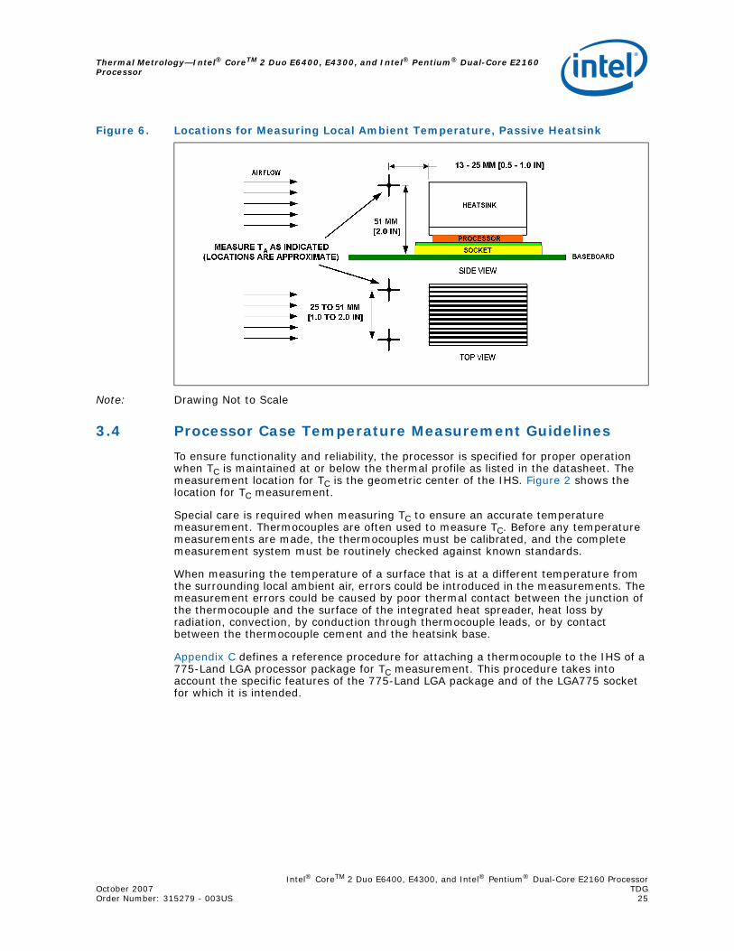
For passive heatsinks, thermocouples should be placed approximately 13 mm to 25 mm [0.5 to 1.0 in] away from processor and heatsink as shown in Figure 5. The thermocouples should be placed approximately 51 mm [2.0 in] above the baseboard. This placement guideline is meant to minimize the effect of localized hot spots from baseboard components.
Note: Testing an active heatsink with a variable speed fan can be done in a thermal chamber to capture the worst-case thermal environment scenarios. Otherwise, when doing a bench top test at room temperature, the fan regulation prevents the heatsink from operating at its maximum capability. To characterize the heatsink capability in the worst-case environment in these conditions, it is then necessary to disable the fan regulation and power the fan directly, based on guidance from the fan supplier.
Note: Drawing Not to Scale
Figure 5. Locations for Measuring Local Ambient Temperature, Active Heatsink
Intel® CoreTM 2 Duo E6400, E4300, and Intel® Pentium® Dual-Core E2160 ProcessorOctober 2007 TDGOrder Number: 315279 - 003US 25
Thermal Metrology—Intel® CoreTM 2 Duo E6400, E4300, and Intel® Pentium® Dual-Core E2160 Processor
Note: Drawing Not to Scale
3.4 Processor Case Temperature Measurement Guidelines
To ensure functionality and reliability, the processor is specified for proper operation when TC is maintained at or below the thermal profile as listed in the datasheet. The measurement location for TC is the geometric center of the IHS. Figure 2 shows the location for TC measurement.
Special care is required when measuring TC to ensure an accurate temperature measurement. Thermocouples are often used to measure TC. Before any temperature measurements are made, the thermocouples must be calibrated, and the complete measurement system must be routinely checked against known standards.
When measuring the temperature of a surface that is at a different temperature from the surrounding local ambient air, errors could be introduced in the measurements. The measurement errors could be caused by poor thermal contact between the junction of the thermocouple and the surface of the integrated heat spreader, heat loss by radiation, convection, by conduction through thermocouple leads, or by contact between the thermocouple cement and the heatsink base.
Appendix C defines a reference procedure for attaching a thermocouple to the IHS of a 775-Land LGA processor package for TC measurement. This procedure takes into account the specific features of the 775-Land LGA package and of the LGA775 socket for which it is intended.
Figure 6. Locations for Measuring Local Ambient Temperature, Passive Heatsink
Intel® CoreTM 2 Duo E6400, E4300, and Intel® Pentium® Dual-Core E2160 Processor—ThermalManagement Logic and Thermal Monitor Feature
Intel® CoreTM 2 Duo E6400, E4300, and Intel® Pentium® Dual-Core E2160 ProcessorTDG October 200726 Order Number: 315279 - 003US
4.0 Thermal Management Logic and Thermal Monitor Feature
4.1 Processor Power Dissipation
An increase in processor operating frequency not only increases system performance, but also increases the processor power dissipation. The relationship between frequency and power is generalized in the following equation: P = CV2F (where P = power, C = capacitance, V = voltage, F = frequency). From this equation, it is evident that power increases linearly with frequency and with the square of voltage. In the absence of power saving technologies, ever increasing frequencies will result in processors with power dissipations in the hundreds of watts. Fortunately, there are numerous ways to reduce the power consumption of a processor, and Intel is aggressively pursuing low power design techniques. For example, decreasing the operating voltage, reducing unnecessary transistor activity, and using more power efficient circuits can significantly reduce processor power consumption.
An on-die thermal management feature called Intel® Thermal Monitor is available on the processor. It provides a thermal management approach to support the continued increases in processor frequency and performance. By using a highly accurate on-die temperature sensing circuit and a fast acting Thermal Control Circuit (TCC), the processor can rapidly initiate thermal management control. The Thermal Monitor can reduce cooling solution cost by allowing thermal designs to target TDP.
The processor also supports an additional power reduction capability known as Intel® Thermal Monitor 2 described in Section 4.2.3.
4.2 Thermal Monitor Implementation
The Thermal Monitor consists of the following components:
• A highly accurate on-die temperature sensing circuit.
• A bi-directional signal (PROCHOT#) that indicates if the processor has exceeded its maximum temperature or can be asserted externally to activate the Thermal Control Circuit (TCC) (Refer to Section 4.2.1 for more details on user activation of TCC via PROCHOT# signal).
• FORCEPR# signal that will activate the TCC.
• A Thermal Control Circuit that will attempt to reduce processor temperature by rapidly reducing power consumption when the on-die temperature sensor indicates that it has exceeded the maximum operating point.
• Registers to determine the processor thermal status.

Intel® CoreTM 2 Duo E6400, E4300, and Intel® Pentium® Dual-Core E2160 ProcessorOctober 2007 TDGOrder Number: 315279 - 003US 27
Thermal Management Logic and Thermal Monitor Feature—Intel® CoreTM 2 Duo E6400, E4300, and Intel® Pentium® Dual-Core E2160 Processor
4.2.1 PROCHOT# Signal
The primary function of the PROCHOT# signal is to provide an external indication that the processor has exceeded its maximum operating temperature. While PROCHOT# is asserted, the TCC will be active. Assertion of the PROCHOT# signal is independent of any register settings within the processor. It is asserted any time the processor die temperature reaches the trip point.
PROCHOT# can be configured via BIOS as an output or bi-directional signal. As an output, PROCHOT# will go active when the processor temperature of either core exceeds its maximum operating temperature. This indicates that the TCC has been activated. As an input, assertion of PROCHOT# will activate the TCC for both cores. The TCC will remain active until the system de-asserts PROCHOT#.
The temperature at which the PROCHOT# signal goes active is individually calibrated during manufacturing. The power dissipation of each processor affects the set point temperature. The temperature where PROCHOT# goes active roughly parallels the thermal profile. Once configured, the processor temperature at which the PROCHOT# signal is asserted is not re-configurable.
One application of using PROCHOT# is the thermal protection of voltage regulators (VR). System designers can create a circuit to monitor the VR temperature and activate the TCC when the temperature limit of the VR is reached. By asserting PROCHOT# (pulled-low) or FORCEPR#, which activates the TCC, the VR can cool down as a result of reduced processor power consumption. Bi-directional PROCHOT# can allow VR thermal designs to target maximum sustained current instead of maximum current. Systems should still provide proper cooling for the VR, and rely on a bi-directional PROCHOT# signal only as a backup in case of system cooling failure.
Note: A thermal solution designed to meet the thermal profile targets should rarely experience activation of the TCC as indicated by the PROCHOT# signal going active.
4.2.2 Thermal Control Circuit
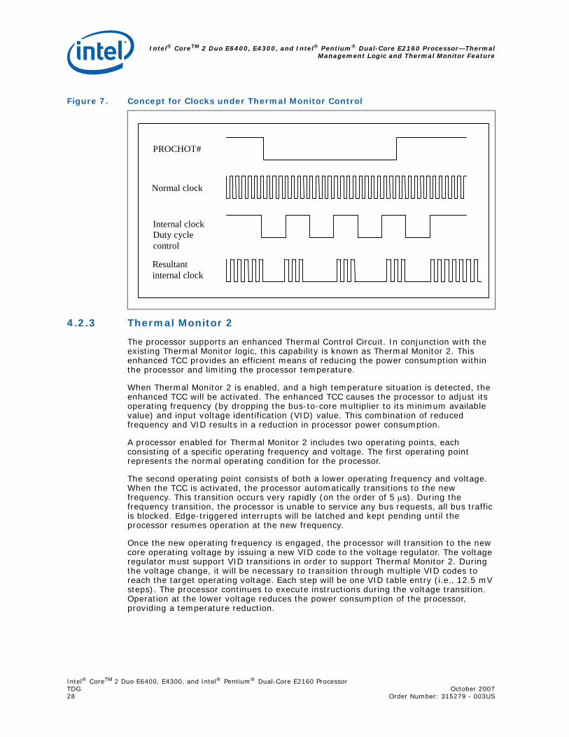
The Thermal Control Circuit portion of the Thermal Monitor must be enabled for the processor to operate within specifications. The Thermal Monitor's TCC, when active, will attempt to lower the processor temperature by reducing the processor power consumption. In the original implementation of thermal monitor this is done by changing the duty cycle of the internal processor clocks, resulting in a lower effective frequency. When active, the TCC turns the processor clocks off and then back on with a predetermined duty cycle. The duty cycle is processor specific, and is fixed for a particular processor. The maximum time period the clocks are disabled is ~3 μs. This time period is frequency dependent and higher frequency processors will disable the internal clocks for a shorter time period. Figure 7 illustrates the relationship between the internal processor clocks and PROCHOT#.
Performance counter registers, status bits in model specific registers (MSRs), and the PROCHOT# output pin are available to monitor the Thermal Monitor behavior.
Intel® CoreTM 2 Duo E6400, E4300, and Intel® Pentium® Dual-Core E2160 Processor—ThermalManagement Logic and Thermal Monitor Feature
Intel® CoreTM 2 Duo E6400, E4300, and Intel® Pentium® Dual-Core E2160 ProcessorTDG October 200728 Order Number: 315279 - 003US
4.2.3 Thermal Monitor 2
The processor supports an enhanced Thermal Control Circuit. In conjunction with the existing Thermal Monitor logic, this capability is known as Thermal Monitor 2. This enhanced TCC provides an efficient means of reducing the power consumption within the processor and limiting the processor temperature.
When Thermal Monitor 2 is enabled, and a high temperature situation is detected, the enhanced TCC will be activated. The enhanced TCC causes the processor to adjust its operating frequency (by dropping the bus-to-core multiplier to its minimum available value) and input voltage identification (VID) value. This combination of reduced frequency and VID results in a reduction in processor power consumption.
A processor enabled for Thermal Monitor 2 includes two operating points, each consisting of a specific operating frequency and voltage. The first operating point represents the normal operating condition for the processor.
The second operating point consists of both a lower operating frequency and voltage. When the TCC is activated, the processor automatically transitions to the new frequency. This transition occurs very rapidly (on the order of 5 μs). During the frequency transition, the processor is unable to service any bus requests, all bus traffic is blocked. Edge-triggered interrupts will be latched and kept pending until the processor resumes operation at the new frequency.
Once the new operating frequency is engaged, the processor will transition to the new core operating voltage by issuing a new VID code to the voltage regulator. The voltage regulator must support VID transitions in order to support Thermal Monitor 2. During the voltage change, it will be necessary to transition through multiple VID codes to reach the target operating voltage. Each step will be one VID table entry (i.e., 12.5 mV steps). The processor continues to execute instructions during the voltage transition. Operation at the lower voltage reduces the power consumption of the processor, providing a temperature reduction.
Figure 7. Concept for Clocks under Thermal Monitor Control
PROCHOT#
Resultant internal clock
Normal clock
Internal clock Duty cycle control
Intel® CoreTM 2 Duo E6400, E4300, and Intel® Pentium® Dual-Core E2160 ProcessorOctober 2007 TDGOrder Number: 315279 - 003US 29
Thermal Management Logic and Thermal Monitor Feature—Intel® CoreTM 2 Duo E6400, E4300, and Intel® Pentium® Dual-Core E2160 Processor
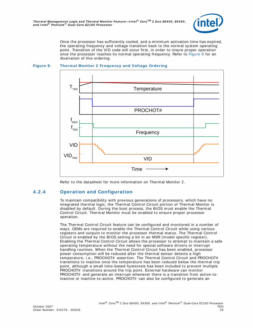
Once the processor has sufficiently cooled, and a minimum activation time has expired, the operating frequency and voltage transition back to the normal system operating point. Transition of the VID code will occur first, in order to insure proper operation once the processor reaches its normal operating frequency. Refer to Figure 8 for an illustration of this ordering.
Refer to the datasheet for more information on Thermal Monitor 2.
4.2.4 Operation and Configuration
To maintain compatibility with previous generations of processors, which have no integrated thermal logic, the Thermal Control Circuit portion of Thermal Monitor is disabled by default. During the boot process, the BIOS must enable the Thermal Control Circuit. Thermal Monitor must be enabled to ensure proper processor operation.
The Thermal Control Circuit feature can be configured and monitored in a number of ways. OEMs are required to enable the Thermal Control Circuit while using various registers and outputs to monitor the processor thermal status. The Thermal Control Circuit is enabled by the BIOS setting a bit in an MSR (model specific register). Enabling the Thermal Control Circuit allows the processor to attempt to maintain a safe operating temperature without the need for special software drivers or interrupt handling routines. When the Thermal Control Circuit has been enabled, processor power consumption will be reduced after the thermal sensor detects a high temperature, i.e., PROCHOT# assertion. The Thermal Control Circuit and PROCHOT# transitions to inactive once the temperature has been reduced below the thermal trip point, although a small time-based hysteresis has been included to prevent multiple PROCHOT# transitions around the trip point. External hardware can monitor PROCHOT# and generate an interrupt whenever there is a transition from active-to-inactive or inactive-to-active. PROCHOT# can also be configured to generate an
Figure 8. Thermal Monitor 2 Frequency and Voltage Ordering
VID
Frequency
TemperatureTTM2
fMAX
fTM2
VID
VIDTM2
PROCHOT#
Time
Intel® CoreTM 2 Duo E6400, E4300, and Intel® Pentium® Dual-Core E2160 Processor—ThermalManagement Logic and Thermal Monitor Feature
Intel® CoreTM 2 Duo E6400, E4300, and Intel® Pentium® Dual-Core E2160 ProcessorTDG October 200730 Order Number: 315279 - 003US
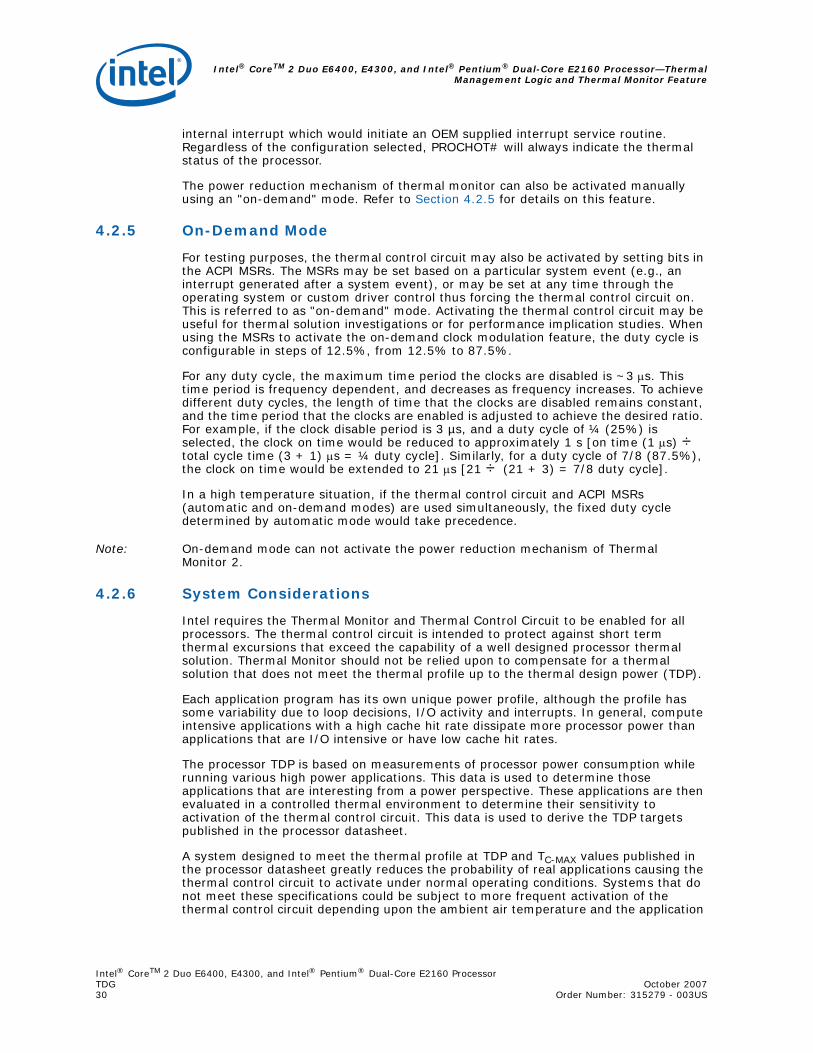
internal interrupt which would initiate an OEM supplied interrupt service routine. Regardless of the configuration selected, PROCHOT# will always indicate the thermal status of the processor.
The power reduction mechanism of thermal monitor can also be activated manually using an "on-demand" mode. Refer to Section 4.2.5 for details on this feature.
4.2.5 On-Demand Mode
For testing purposes, the thermal control circuit may also be activated by setting bits in the ACPI MSRs. The MSRs may be set based on a particular system event (e.g., an interrupt generated after a system event), or may be set at any time through the operating system or custom driver control thus forcing the thermal control circuit on. This is referred to as "on-demand" mode. Activating the thermal control circuit may be useful for thermal solution investigations or for performance implication studies. When using the MSRs to activate the on-demand clock modulation feature, the duty cycle is configurable in steps of 12.5%, from 12.5% to 87.5%.
For any duty cycle, the maximum time period the clocks are disabled is ~3 μs. This time period is frequency dependent, and decreases as frequency increases. To achieve different duty cycles, the length of time that the clocks are disabled remains constant, and the time period that the clocks are enabled is adjusted to achieve the desired ratio. For example, if the clock disable period is 3 µs, and a duty cycle of ¼ (25%) is selected, the clock on time would be reduced to approximately 1 s [on time (1 μs) ÷ total cycle time (3 + 1) μs = ¼ duty cycle]. Similarly, for a duty cycle of 7/8 (87.5%), the clock on time would be extended to 21 μs [21 ÷ (21 + 3) = 7/8 duty cycle].
In a high temperature situation, if the thermal control circuit and ACPI MSRs (automatic and on-demand modes) are used simultaneously, the fixed duty cycle determined by automatic mode would take precedence.
Note: On-demand mode can not activate the power reduction mechanism of Thermal Monitor 2.
4.2.6 System Considerations
Intel requires the Thermal Monitor and Thermal Control Circuit to be enabled for all processors. The thermal control circuit is intended to protect against short term thermal excursions that exceed the capability of a well designed processor thermal solution. Thermal Monitor should not be relied upon to compensate for a thermal solution that does not meet the thermal profile up to the thermal design power (TDP).
Each application program has its own unique power profile, although the profile has some variability due to loop decisions, I/O activity and interrupts. In general, compute intensive applications with a high cache hit rate dissipate more processor power than applications that are I/O intensive or have low cache hit rates.
The processor TDP is based on measurements of processor power consumption while running various high power applications. This data is used to determine those applications that are interesting from a power perspective. These applications are then evaluated in a controlled thermal environment to determine their sensitivity to activation of the thermal control circuit. This data is used to derive the TDP targets published in the processor datasheet.
A system designed to meet the thermal profile at TDP and TC-MAX values published in the processor datasheet greatly reduces the probability of real applications causing the thermal control circuit to activate under normal operating conditions. Systems that do not meet these specifications could be subject to more frequent activation of the thermal control circuit depending upon the ambient air temperature and the application
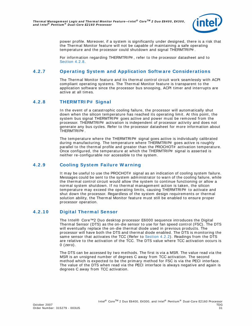
Intel® CoreTM 2 Duo E6400, E4300, and Intel® Pentium® Dual-Core E2160 ProcessorOctober 2007 TDGOrder Number: 315279 - 003US 31
Thermal Management Logic and Thermal Monitor Feature—Intel® CoreTM 2 Duo E6400, E4300, and Intel® Pentium® Dual-Core E2160 Processor
power profile. Moreover, if a system is significantly under designed, there is a risk that the Thermal Monitor feature will not be capable of maintaining a safe operating temperature and the processor could shutdown and signal THERMTRIP#.
For information regarding THERMTRIP#, refer to the processor datasheet and to Section 4.2.8.
4.2.7 Operating System and Application Software Considerations
The Thermal Monitor feature and its thermal control circuit work seamlessly with ACPI compliant operating systems. The Thermal Monitor feature is transparent to the application software since the processor bus snooping, ACPI timer and interrupts are active at all times.
4.2.8 THERMTRIP# Signal
In the event of a catastrophic cooling failure, the processor will automatically shut down when the silicon temperature has reached its operating limit. At this point, the system bus signal THERMTRIP# goes active and power must be removed from the processor. THERMTRIP# activation is independent of processor activity and does not generate any bus cycles. Refer to the processor datasheet for more information about THERMTRIP#.
The temperature where the THERMTRIP# signal goes active is individually calibrated during manufacturing. The temperature where THERMTRIP# goes active is roughly parallel to the thermal profile and greater than the PROCHOT# activation temperature. Once configured, the temperature at which the THERMTRIP# signal is asserted is neither re-configurable nor accessible to the system.
4.2.9 Cooling System Failure Warning
It may be useful to use the PROCHOT# signal as an indication of cooling system failure. Messages could be sent to the system administrator to warn of the cooling failure, while the thermal control circuit would allow the system to continue functioning or allow a normal system shutdown. If no thermal management action is taken, the silicon temperature may exceed the operating limits, causing THERMTRIP# to activate and shut down the processor. Regardless of the system design requirements or thermal solution ability, the Thermal Monitor feature must still be enabled to ensure proper processor operation.
4.2.10 Digital Thermal Sensor
The Intel® Core™2 Duo desktop processor E6000 sequence introduces the Digital Thermal Sensor (DTS) as the on-die sensor to use for fan speed control (FSC). The DTS will eventually replace the on-die thermal diode used in previous products. The processor will have both the DTS and thermal diode enabled. The DTS is monitoring the same sensor that activates the TCC (Refer to Section 4.2.2). Readings from the DTS are relative to the activation of the TCC. The DTS value where TCC activation occurs is 0 (zero).
The DTS can be accessed by two methods. The first is via a MSR. The value read via the MSR is an unsigned number of degrees C away from TCC activation. The second method which is expected to be the primary method for FSC is via the PECI interface. The value of the DTS when read via the PECI interface is always negative and again is degrees C away from TCC activation.
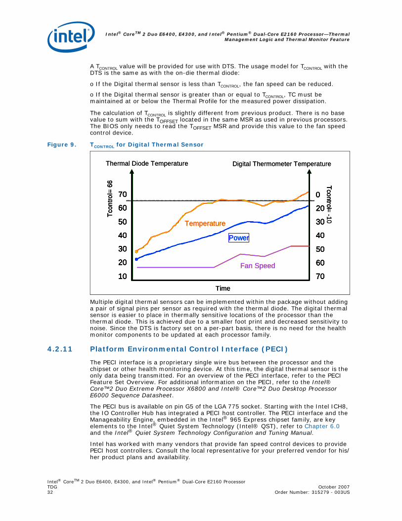
Intel® CoreTM 2 Duo E6400, E4300, and Intel® Pentium® Dual-Core E2160 Processor—ThermalManagement Logic and Thermal Monitor Feature
Intel® CoreTM 2 Duo E6400, E4300, and Intel® Pentium® Dual-Core E2160 ProcessorTDG October 200732 Order Number: 315279 - 003US
A TCONTROL value will be provided for use with DTS. The usage model for TCONTROL with the DTS is the same as with the on-die thermal diode:
o If the Digital thermal sensor is less than TCONTROL, the fan speed can be reduced.
o If the Digital thermal sensor is greater than or equal to TCONTROL, TC must be maintained at or below the Thermal Profile for the measured power dissipation.
The calculation of TCONTROL is slightly different from previous product. There is no base value to sum with the TOFFSET located in the same MSR as used in previous processors. The BIOS only needs to read the TOFFSET MSR and provide this value to the fan speed control device.
Multiple digital thermal sensors can be implemented within the package without adding a pair of signal pins per sensor as required with the thermal diode. The digital thermal sensor is easier to place in thermally sensitive locations of the processor than the thermal diode. This is achieved due to a smaller foot print and decreased sensitivity to noise. Since the DTS is factory set on a per-part basis, there is no need for the health monitor components to be updated at each processor family.
4.2.11 Platform Environmental Control Interface (PECI)
The PECI interface is a proprietary single wire bus between the processor and the chipset or other health monitoring device. At this time, the digital thermal sensor is the only data being transmitted. For an overview of the PECI interface, refer to the PECI Feature Set Overview. For additional information on the PECI, refer to the Intel® Core™2 Duo Extreme Processor X6800 and Intel® Core™2 Duo Desktop Processor E6000 Sequence Datasheet.
The PECI bus is available on pin G5 of the LGA 775 socket. Starting with the Intel ICH8, the IO Controller Hub has integrated a PECI host controller. The PECI interface and the Manageability Engine, embedded in the Intel® 965 Express chipset family, are key elements to the Intel® Quiet System Technology (Intel® QST), refer to Chapter 6.0 and the Intel® Quiet System Technology Configuration and Tuning Manual.
Intel has worked with many vendors that provide fan speed control devices to provide PECI host controllers. Consult the local representative for your preferred vendor for his/her product plans and availability.
Figure 9. TCONTROL for Digital Thermal Sensor
Digital Thermometer Temperature
30
20
10
70
60
50
40
30
20
0
70
60
50
40
Tcon
trol=
66 Tcontrol= -10
Fan Speed
Temperature
Time
Power
Thermal Diode Temperature
30
20
10
70
60
50
40
30
20
10
70
60
50
40
30
20
0
70
60
50
40
30
20
0
70
60
50
40
Tcon
trol=
66 Tcontrol
Fan Speed
Temperature
Time
Power
Digital Thermometer Temperature
30
20
10
70
60
50
40
30
20
0
70
60
50
40
Tcon
trol=
66 Tcontrol= -10
Fan Speed
Temperature
Time
Power
Thermal Diode Temperature
30
20
10
70
60
50
40
30
20
10
70
60
50
40
30
20
0
70
60
50
40
30
20
0
70
60
50
40
Tcon
trol=
66 Tcontrol
Fan Speed
Temperature
Time
Power
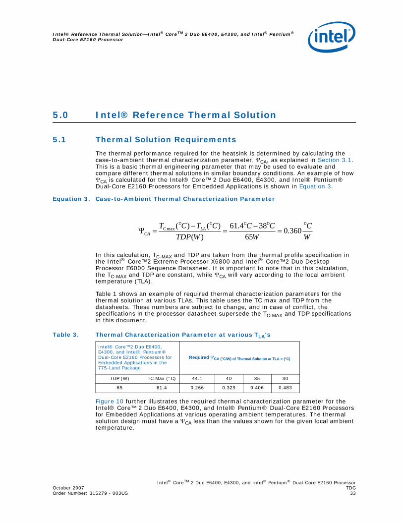
Intel® CoreTM 2 Duo E6400, E4300, and Intel® Pentium® Dual-Core E2160 ProcessorOctober 2007 TDGOrder Number: 315279 - 003US 33
Intel® Reference Thermal Solution—Intel® CoreTM 2 Duo E6400, E4300, and Intel® Pentium® Dual-Core E2160 Processor
5.0 Intel® Reference Thermal Solution
5.1 Thermal Solution Requirements
The thermal performance required for the heatsink is determined by calculating the case-to-ambient thermal characterization parameter, ΨCA, as explained in Section 3.1. This is a basic thermal engineering parameter that may be used to evaluate and compare different thermal solutions in similar boundary conditions. An example of how ΨCA is calculated for the Intel® Core™ 2 Duo E6400, E4300, and Intel® Pentium® Dual-Core E2160 Processors for Embedded Applications is shown in Equation 3.
Equation 3. Case-to-Ambient Thermal Characterization Parameter
In this calculation, TC-MAX and TDP are taken from the thermal profile specification in the Intel® Core™2 Extreme Processor X6800 and Intel® Core™2 Duo Desktop Processor E6000 Sequence Datasheet. It is important to note that in this calculation, the TC-MAX and TDP are constant, while ΨCA will vary according to the local ambient temperature (TLA).
Table 1 shows an example of required thermal characterization parameters for the thermal solution at various TLAs. This table uses the TC max and TDP from the datasheets. These numbers are subject to change, and in case of conflict, the specifications in the processor datasheet supersede the TC-MAX and TDP specifications in this document.
Figure 10 further illustrates the required thermal characterization parameter for the Intel® Core™ 2 Duo E6400, E4300, and Intel® Pentium® Dual-Core E2160 Processors for Embedded Applications at various operating ambient temperatures. The thermal solution design must have a ΨCA less than the values shown for the given local ambient temperature.
WC
WCC
WTDPCTCT LAC
CA
ooooo
360.065
384.61)(
)()(max =−
=−
=Ψ
Table 3. Thermal Characterization Parameter at various TLA's
Intel® Core™2 Duo E6400, E4300, and Intel® Pentium® Dual-Core E2160 Processors for Embedded Applications in the 775-Land Package
Required ΨCA (°C/W) of Thermal Solution at TLA = (°C)
TDP (W) TC Max (°C) 44.1 40 35 30
65 61.4 0.266 0.329 0.406 0.483
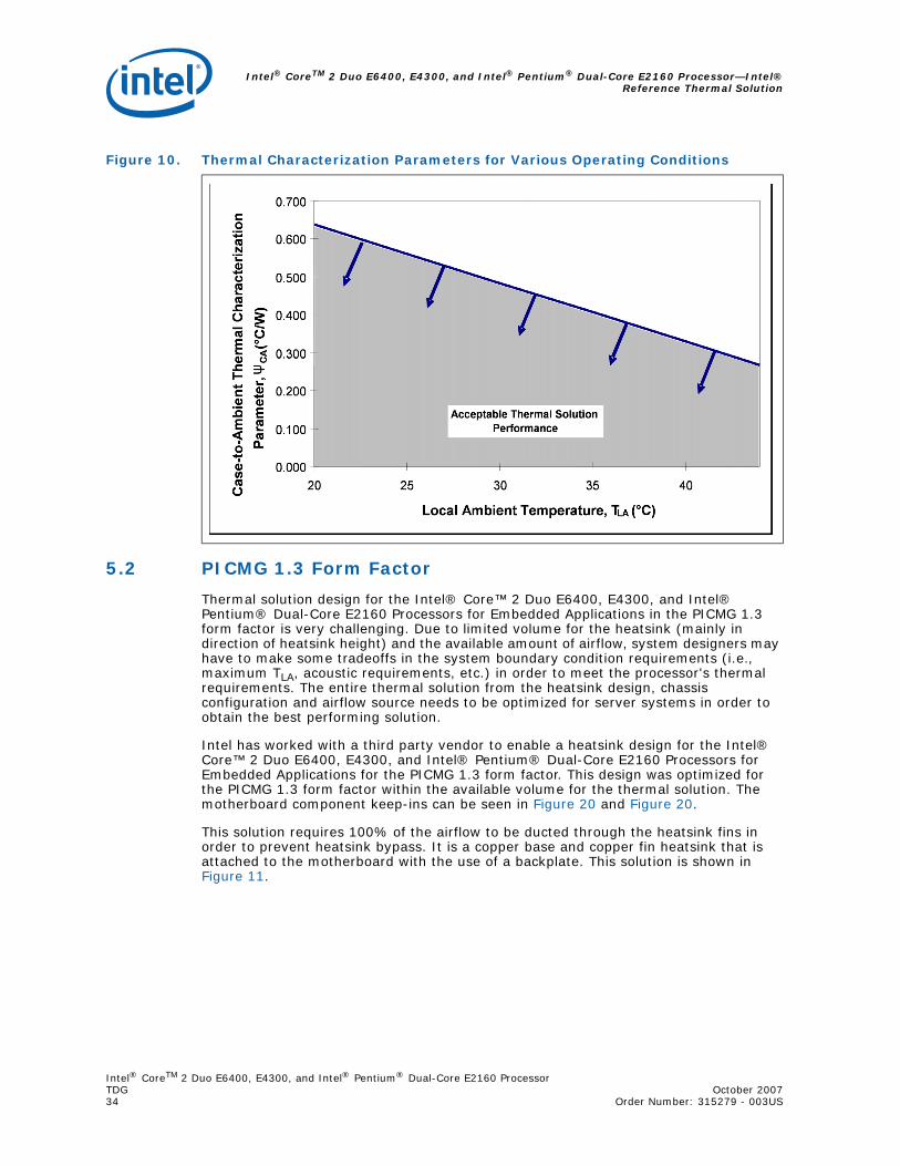
Intel® CoreTM 2 Duo E6400, E4300, and Intel® Pentium® Dual-Core E2160 Processor—Intel®Reference Thermal Solution
Intel® CoreTM 2 Duo E6400, E4300, and Intel® Pentium® Dual-Core E2160 ProcessorTDG October 200734 Order Number: 315279 - 003US
5.2 PICMG 1.3 Form Factor
Thermal solution design for the Intel® Core™ 2 Duo E6400, E4300, and Intel® Pentium® Dual-Core E2160 Processors for Embedded Applications in the PICMG 1.3 form factor is very challenging. Due to limited volume for the heatsink (mainly in direction of heatsink height) and the available amount of airflow, system designers may have to make some tradeoffs in the system boundary condition requirements (i.e., maximum TLA, acoustic requirements, etc.) in order to meet the processor's thermal requirements. The entire thermal solution from the heatsink design, chassis configuration and airflow source needs to be optimized for server systems in order to obtain the best performing solution.
Intel has worked with a third party vendor to enable a heatsink design for the Intel® Core™ 2 Duo E6400, E4300, and Intel® Pentium® Dual-Core E2160 Processors for Embedded Applications for the PICMG 1.3 form factor. This design was optimized for the PICMG 1.3 form factor within the available volume for the thermal solution. The motherboard component keep-ins can be seen in Figure 20 and Figure 20.
This solution requires 100% of the airflow to be ducted through the heatsink fins in order to prevent heatsink bypass. It is a copper base and copper fin heatsink that is attached to the motherboard with the use of a backplate. This solution is shown in Figure 11.
Figure 10. Thermal Characterization Parameters for Various Operating Conditions
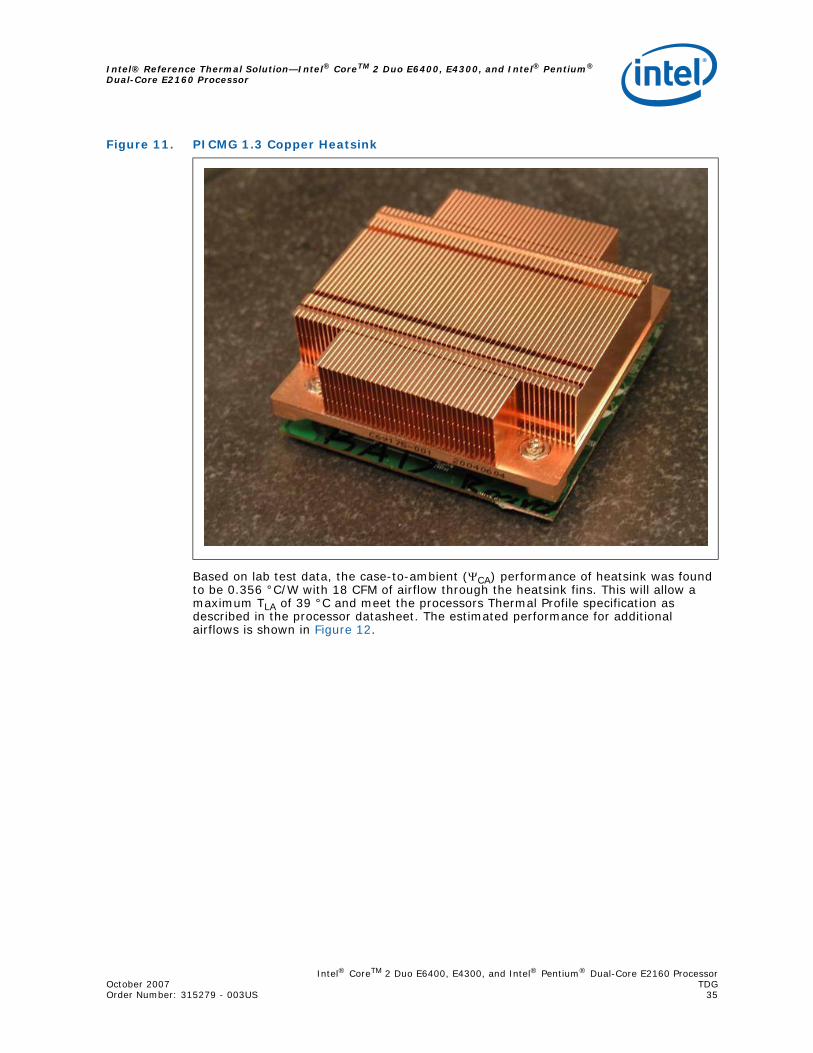
Intel® CoreTM 2 Duo E6400, E4300, and Intel® Pentium® Dual-Core E2160 ProcessorOctober 2007 TDGOrder Number: 315279 - 003US 35
Intel® Reference Thermal Solution—Intel® CoreTM 2 Duo E6400, E4300, and Intel® Pentium® Dual-Core E2160 Processor
Based on lab test data, the case-to-ambient (ΨCA) performance of heatsink was found to be 0.356 °C/W with 18 CFM of airflow through the heatsink fins. This will allow a maximum TLA of 39 °C and meet the processors Thermal Profile specification as described in the processor datasheet. The estimated performance for additional airflows is shown in Figure 12.
Figure 11. PICMG 1.3 Copper Heatsink
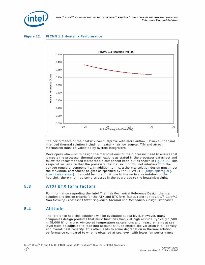
Intel® CoreTM 2 Duo E6400, E4300, and Intel® Pentium® Dual-Core E2160 Processor—Intel®Reference Thermal Solution
Intel® CoreTM 2 Duo E6400, E4300, and Intel® Pentium® Dual-Core E2160 ProcessorTDG October 200736 Order Number: 315279 - 003US
The performance of the heatsink could improve with more airflow. However, the final intended thermal solution including, heatsink, airflow source, TIM and attach mechanism must be validated by system integrators.
Developers who wish to design thermal solutions for the processor, need to ensure that it meets the processor thermal specifications as stated in the processor datasheet and follow the recommended motherboard component keep-out as shown in Figure 20. This keep-out will ensure that the processor thermal solution will not interfere with the voltage regulator components. In addition to this, a thermal solution design must meet the maximum component heights as specified by the PICMG 1.3 (http://picmg.org/specifications.stm). It should be noted that due to the vertical orientation of the heatsink, there might be some stresses in the board due to the heatsink weight.
5.3 ATX/BTX form factors
For information regarding the Intel Thermal/Mechanical Reference Design thermal solution and design criteria for the ATX and BTX form factor, refer to the Intel® Core™2 Duo Desktop Processor E6000 Sequence Thermal and Mechanical Design Guidelines.
5.4 Altitude
The reference heatsink solutions will be evaluated at sea level. However, many companies design products that must function reliably at high altitude, typically 1,500 m [5,000 ft] or more. Air-cooled temperature calculations and measurements at sea level must be adjusted to take into account altitude effects like variation in air density and overall heat capacity. This often leads to some degradation in thermal solution performance compared to what is obtained at sea level, with lower fan performance
Figure 12. PICMG 1.3 Heatsink Performance
PICMG 1.3 Heatsink Psi_ca
0.000
0.050
0.100
0.150
0.200
0.250
0.300
0.350
0.400
0.450
10 15 20 25 30 35Airflow Throught the Fins (CFM)
Ther
mal
Res
ista
nce
(o C/W
)
Intel® CoreTM 2 Duo E6400, E4300, and Intel® Pentium® Dual-Core E2160 ProcessorOctober 2007 TDGOrder Number: 315279 - 003US 37
Intel® Reference Thermal Solution—Intel® CoreTM 2 Duo E6400, E4300, and Intel® Pentium® Dual-Core E2160 Processor
and higher surface temperatures. The system designer needs to account for altitude effects in the overall system thermal design to make sure that the TC requirement for the processor is met at the targeted altitude.
5.5 Geometric Envelope for Intel Reference PICMG 1.3 Thermal Mechanical Design
Figure 20 and Figure 21 in Appendix D give detailed reference PICMG 1.3 motherboard keep-out information for the reference thermal/mechanical enabling design. These drawings include height restrictions in the enabling component region.
Intel® CoreTM 2 Duo E6400, E4300, and Intel® Pentium® Dual-Core E2160 Processor—Intel®Quiet System Technology (Intel® QST)
Intel® CoreTM 2 Duo E6400, E4300, and Intel® Pentium® Dual-Core E2160 ProcessorTDG October 200738 Order Number:315279 -003US
6.0 Intel® Quiet System Technology (Intel® QST)
In the Intel® 965 Express Chipset family, a new control algorithm for fan speed control is being introduced. It is composed of a Manageability Engine (ME) in the Graphics Memory Controller Hub (GMCH) which executes the Intel® Quiet System Technology (Intel® QST) algorithm and the ICH8 containing the sensor bus and fan control circuits.
The ME provides integrated fan speed control in lieu of the mechanisms available in a SIO or a stand-alone ASIC. The Intel QST is time based as compared to the linear or state control used by the current generation of FSC devices.
A short discussion of Intel QST will follow along with thermal solution design recommendations. For a complete discussion of programming the Intel QST in the ME, consult the Intel® Quiet System Technology (Intel® QST) Configuration and Tuning Manual.
Note: Fan speed control algorithms and Intel QST in particular rely on a thermal solution being compliant to the processor thermal profile. It is unlikely that any fan speed control algorithm can compensate for a non-compliant thermal solution. See Chapter 5.0 and Chapter 6.0 for thermal solution requirements that should be met before evaluating or configuring a system with Intel QST.
6.1 Intel® QST Algorithm
The objective of Intel QST is to minimize the system acoustics by more closely controlling the thermal sensors to the corresponding processor or chipset device TCONTROL value. This is achieved by the use of a Proportional-Integral-Derivative (PID) control algorithm and a Fan Output Weighting Matrix. The PID algorithm takes into account the difference between the current temperature and the target (TCONTROL), the rate of change and direction of change to minimize the required fan speed change. The Fan Output Weighting Matrix uses the effects of each fan on a thermal sensor to minimize the required fan speed changes
Figure 13 shows in a very simple manner how Intel QST works. Refer to the Intel® Quiet System Technology (Intel® QST) Configuration and Tuning Manual for details of the inputs and response.
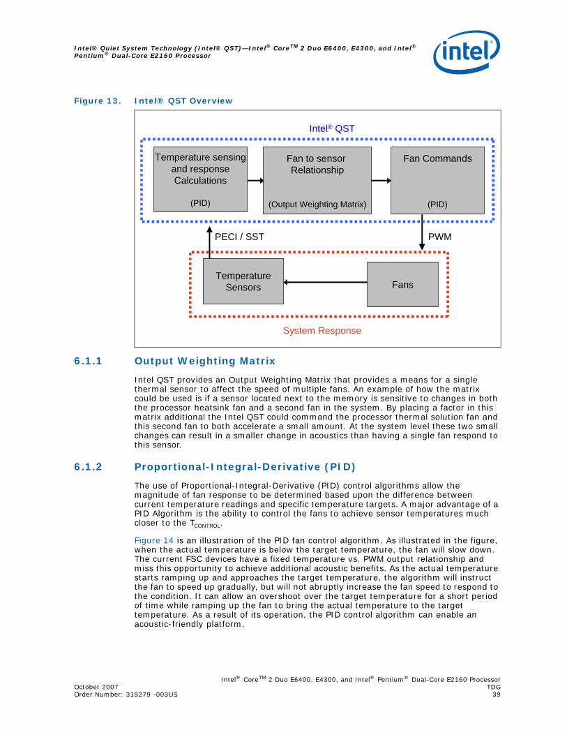
Intel® CoreTM 2 Duo E6400, E4300, and Intel® Pentium® Dual-Core E2160 ProcessorOctober 2007 TDGOrder Number: 315279 -003US 39
Intel® Quiet System Technology (Intel® QST)—Intel® CoreTM 2 Duo E6400, E4300, and Intel® Pentium® Dual-Core E2160 Processor
6.1.1 Output Weighting Matrix
Intel QST provides an Output Weighting Matrix that provides a means for a single thermal sensor to affect the speed of multiple fans. An example of how the matrix could be used is if a sensor located next to the memory is sensitive to changes in both the processor heatsink fan and a second fan in the system. By placing a factor in this matrix additional the Intel QST could command the processor thermal solution fan and this second fan to both accelerate a small amount. At the system level these two small changes can result in a smaller change in acoustics than having a single fan respond to this sensor.
6.1.2 Proportional-Integral-Derivative (PID)
The use of Proportional-Integral-Derivative (PID) control algorithms allow the magnitude of fan response to be determined based upon the difference between current temperature readings and specific temperature targets. A major advantage of a PID Algorithm is the ability to control the fans to achieve sensor temperatures much closer to the TCONTROL.
Figure 14 is an illustration of the PID fan control algorithm. As illustrated in the figure, when the actual temperature is below the target temperature, the fan will slow down. The current FSC devices have a fixed temperature vs. PWM output relationship and miss this opportunity to achieve additional acoustic benefits. As the actual temperature starts ramping up and approaches the target temperature, the algorithm will instruct the fan to speed up gradually, but will not abruptly increase the fan speed to respond to the condition. It can allow an overshoot over the target temperature for a short period of time while ramping up the fan to bring the actual temperature to the target temperature. As a result of its operation, the PID control algorithm can enable an acoustic-friendly platform.
Figure 13. Intel® QST Overview
Fan to sensor Relationship
(Output Weighting Matrix)
Temperature sensingand responseCalculations
(PID)
Fan Commands
(PID)
FansTemperature
Sensors
Intel® QST
System Response
PWMPECI / SST
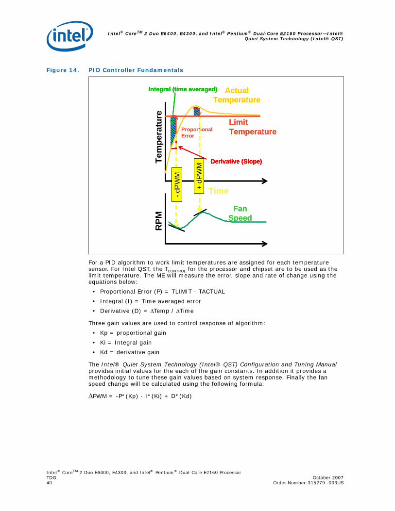
Intel® CoreTM 2 Duo E6400, E4300, and Intel® Pentium® Dual-Core E2160 Processor—Intel®Quiet System Technology (Intel® QST)
Intel® CoreTM 2 Duo E6400, E4300, and Intel® Pentium® Dual-Core E2160 ProcessorTDG October 200740 Order Number:315279 -003US
For a PID algorithm to work limit temperatures are assigned for each temperature sensor. For Intel QST, the TCONTROL for the processor and chipset are to be used as the limit temperature. The ME will measure the error, slope and rate of change using the equations below:
• Proportional Error (P) = TLIMIT - TACTUAL
• Integral (I) = Time averaged error
• Derivative (D) = ΔTemp / ΔTime
Three gain values are used to control response of algorithm:
• Kp = proportional gain
• Ki = Integral gain
• Kd = derivative gain
The Intel® Quiet System Technology (Intel® QST) Configuration and Tuning Manual provides initial values for the each of the gain constants. In addition it provides a methodology to tune these gain values based on system response. Finally the fan speed change will be calculated using the following formula:
ΔPWM = -P*(Kp) - I*(Ki) + D*(Kd)
Figure 14. PID Controller Fundamentals
Proportional Error
Derivative (Slope)
Integral (time averaged)
Proportional Error
Derivative (Slope)
Integral (time averaged)
Proportional Error
Derivative (Slope)
Integral (time averaged)
Proportional Error
Derivative (Slope)
Integral (time averaged)
RPM
Tem
pera
ture
Time+ dP
WM
+ dP
WM
+ dP
WM
+ dP
WM
+ dP
WM
+ dP
WM
-- dP
WM
dPW
M-- d
PW
MdP
WM
-- dP
WM
dPW
M
Actual Temperature
Actual Temperature
Fan Speed
Fan Speed
LimitTemperatureLimitTemperature
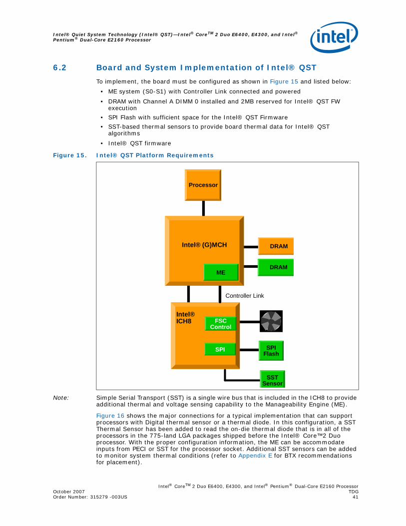
Intel® CoreTM 2 Duo E6400, E4300, and Intel® Pentium® Dual-Core E2160 ProcessorOctober 2007 TDGOrder Number: 315279 -003US 41
Intel® Quiet System Technology (Intel® QST)—Intel® CoreTM 2 Duo E6400, E4300, and Intel® Pentium® Dual-Core E2160 Processor
6.2 Board and System Implementation of Intel® QST
To implement, the board must be configured as shown in Figure 15 and listed below:
• ME system (S0-S1) with Controller Link connected and powered
• DRAM with Channel A DIMM 0 installed and 2MB reserved for Intel® QST FW execution
• SPI Flash with sufficient space for the Intel® QST Firmware
• SST-based thermal sensors to provide board thermal data for Intel® QST algorithms
• Intel® QST firmware
Note: Simple Serial Transport (SST) is a single wire bus that is included in the ICH8 to provide additional thermal and voltage sensing capability to the Manageability Engine (ME).
Figure 16 shows the major connections for a typical implementation that can support processors with Digital thermal sensor or a thermal diode. In this configuration, a SST Thermal Sensor has been added to read the on-die thermal diode that is in all of the processors in the 775-land LGA packages shipped before the Intel® Core™2 Duo processor. With the proper configuration information, the ME can be accommodate inputs from PECI or SST for the processor socket. Additional SST sensors can be added to monitor system thermal conditions (refer to Appendix E for BTX recommendations for placement).
Figure 15. Intel® QST Platform Requirements
Processor
ME
SPI Flash
Intel®ICH8
DRAM
Controller Link
DRAM
FSC Control
SPI
SST Sensor
Intel® (G)MCH
ME
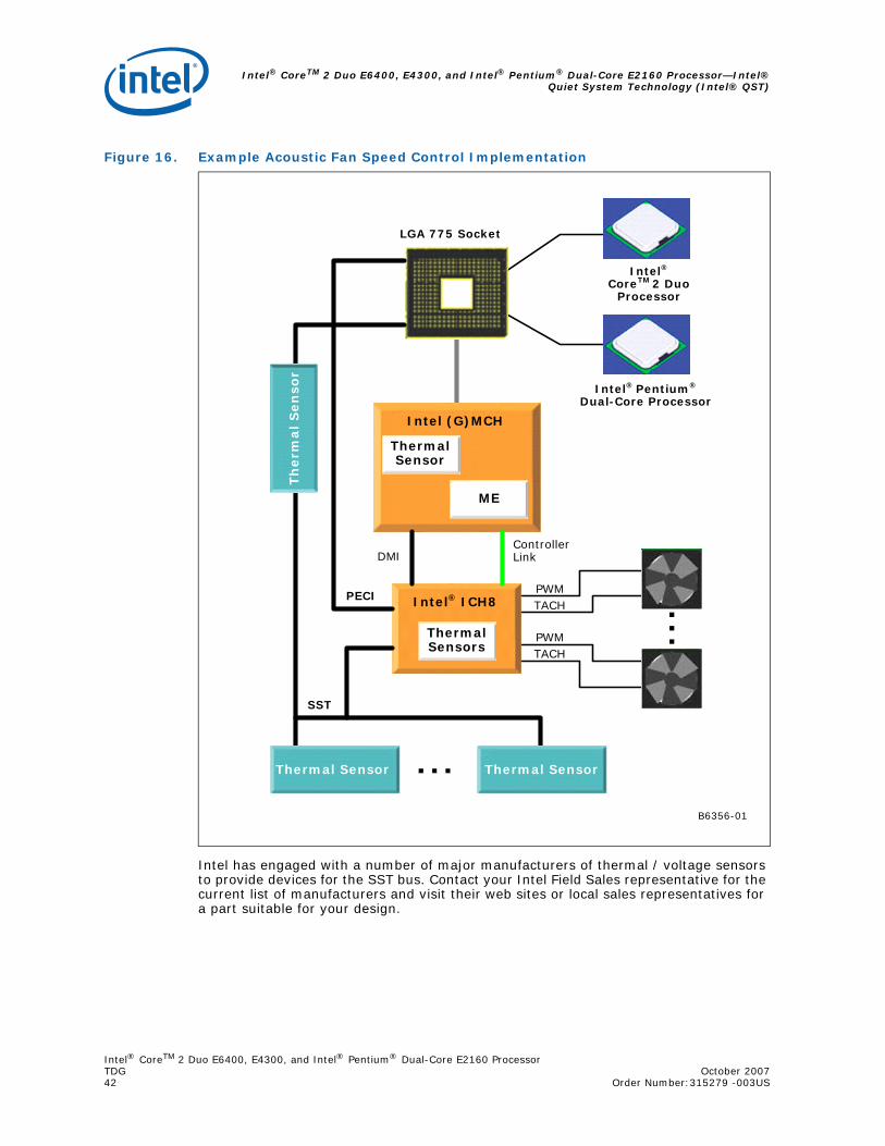
Intel® CoreTM 2 Duo E6400, E4300, and Intel® Pentium® Dual-Core E2160 Processor—Intel®Quiet System Technology (Intel® QST)
Intel® CoreTM 2 Duo E6400, E4300, and Intel® Pentium® Dual-Core E2160 ProcessorTDG October 200742 Order Number:315279 -003US
Intel has engaged with a number of major manufacturers of thermal / voltage sensors to provide devices for the SST bus. Contact your Intel Field Sales representative for the current list of manufacturers and visit their web sites or local sales representatives for a part suitable for your design.
Figure 16. Example Acoustic Fan Speed Control Implementation
B6356-01
ME
Intel (G)MCH
Thermal Sensor
Thermal Sensor
Intel® Pentium®
Dual-Core Processor
Intel®
CoreTM 2 Duo Processor
LGA 775 Socket
Intel® ICH8
Thermal Sensors
Controller Link
PECI
Thermal Sensor
Th
erm
al S
en
sor
SST
DMI
PWMTACH
PWMTACH
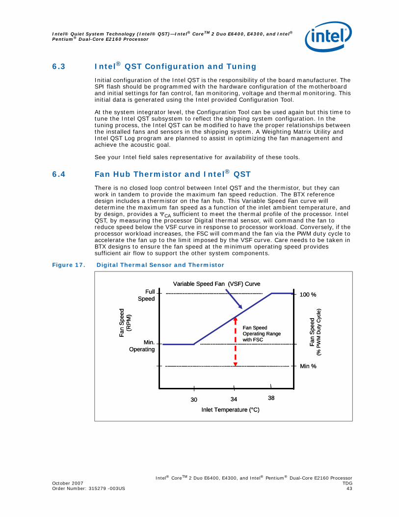
Intel® CoreTM 2 Duo E6400, E4300, and Intel® Pentium® Dual-Core E2160 ProcessorOctober 2007 TDGOrder Number: 315279 -003US 43
Intel® Quiet System Technology (Intel® QST)—Intel® CoreTM 2 Duo E6400, E4300, and Intel® Pentium® Dual-Core E2160 Processor
6.3 Intel® QST Configuration and Tuning
Initial configuration of the Intel QST is the responsibility of the board manufacturer. The SPI flash should be programmed with the hardware configuration of the motherboard and initial settings for fan control, fan monitoring, voltage and thermal monitoring. This initial data is generated using the Intel provided Configuration Tool.
At the system integrator level, the Configuration Tool can be used again but this time to tune the Intel QST subsystem to reflect the shipping system configuration. In the tuning process, the Intel QST can be modified to have the proper relationships between the installed fans and sensors in the shipping system. A Weighting Matrix Utility and Intel QST Log program are planned to assist in optimizing the fan management and achieve the acoustic goal.
See your Intel field sales representative for availability of these tools.
6.4 Fan Hub Thermistor and Intel® QST
There is no closed loop control between Intel QST and the thermistor, but they can work in tandem to provide the maximum fan speed reduction. The BTX reference design includes a thermistor on the fan hub. This Variable Speed Fan curve will determine the maximum fan speed as a function of the inlet ambient temperature, and by design, provides a ΨCA sufficient to meet the thermal profile of the processor. Intel QST, by measuring the processor Digital thermal sensor, will command the fan to reduce speed below the VSF curve in response to processor workload. Conversely, if the processor workload increases, the FSC will command the fan via the PWM duty cycle to accelerate the fan up to the limit imposed by the VSF curve. Care needs to be taken in BTX designs to ensure the fan speed at the minimum operating speed provides sufficient air flow to support the other system components.
Figure 17. Digital Thermal Sensor and Thermistor
Fan
Spee
d(R
PM)
Inlet Temperature (°C)
Full Speed
30 38
Min. Operating
Variable Speed Fan (VSF) Curve
Fan Speed Operating Range with FSC
34
Min %
Fan
Spe
ed
(% P
WM
Dut
y C
ycle
)
100 %
Fan
Spee
d(R
PM)
Inlet Temperature (°C)
Full Speed
30 38
Min. Operating
Variable Speed Fan (VSF) Curve
Fan Speed Operating Range with FSC
34
Min %
Fan
Spe
ed
(% P
WM
Dut
y C
ycle
)
100 %

Intel® CoreTM 2 Duo E6400, E4300, and Intel® Pentium® Dual-Core E2160 Processor—LGA775Socket Heatsink Loading
Intel® CoreTM 2 Duo E6400, E4300, and Intel® Pentium® Dual-Core E2160 ProcessorTDG October 200744 Order Number: 315279 - 003US
Appendix A LGA775 Socket Heatsink Loading
A.1 LGA775 Socket Heatsink Considerations
Heatsink clip load is traditionally used for:
• Mechanical performance in mechanical shock and vibration
• Thermal interface performance
— Required preload depends on TIM
— Preload can be low for thermal grease
In addition to mechanical performance in mechanical shock and vibration and TIM performance, the LGA775 socket requires a minimum heatsink preload to protect against fatigue failure of socket solder joints.
Solder ball tensile stress is originally created when, after inserting a processor into the socket, the LGA775 socket load plate is actuated. In addition, solder joint shear stress is caused by coefficient of thermal expansion (CTE) mismatch induced shear loading. The solder joint compressive axial force (Faxial) induced by the heatsink preload helps to reduce the combined joint tensile and shear stress.
Overall, the heatsink required preload is the minimum preload needed to meet all of the above requirements: Mechanical shock and vibration and TIM performance AND LGA775 socket protection against fatigue failure.
A.2 Metric for Heatsink Preload for Designs Non-Compliant with Intel Reference Design
A.2.1 Heatsink Preload Requirement Limitations
Heatsink preload by itself is not an appropriate metric for solder joint force across various mechanical designs and does not take into account other factors such as:
• Heatsink mounting hole span
• Heatsink clip/fastener assembly stiffness and creep
• Board stiffness and creep
• Board stiffness is modified by fixtures like backing plate, chassis attach, etc.
Simulation shows that the solder joint force (Faxial) is proportional to the board deflection measured along the socket diagonal. The matching of Faxial required to protect the LGA775 socket solder joint in temperature cycling is equivalent to matching a target MB deflection.
Therefore, the heatsink preload for LGA775 socket solder joint protection against fatigue failure can be more generally defined as the load required to create a target board downward deflection throughout the life of the product.
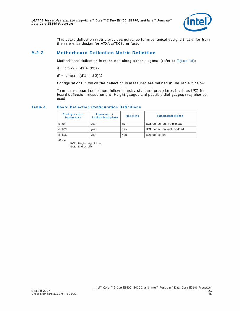
Intel® CoreTM 2 Duo E6400, E4300, and Intel® Pentium® Dual-Core E2160 ProcessorOctober 2007 TDGOrder Number: 315279 - 003US 45
LGA775 Socket Heatsink Loading—Intel® CoreTM 2 Duo E6400, E4300, and Intel® Pentium® Dual-Core E2160 Processor
This board deflection metric provides guidance for mechanical designs that differ from the reference design for ATX//µATX form factor.
A.2.2 Motherboard Deflection Metric Definition
Motherboard deflection is measured along either diagonal (refer to Figure 18):
d = dmax - (d1 + d2)/2
d' = dmax - (d'1 + d'2)/2
Configurations in which the deflection is measured are defined in the Table 2 below.
To measure board deflection, follow industry standard procedures (such as IPC) for board deflection measurement. Height gauges and possibly dial gauges may also be used.
Table 4. Board Deflection Configuration Definitions
Configuration Parameter
Processor + Socket load plate Heatsink Parameter Name
d_ref yes no BOL deflection, no preload
d_BOL yes yes BOL deflection with preload
d_EOL yes yes EOL deflection
Note:BOL: Beginning of LifeEOL: End of Life
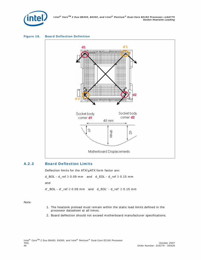
Intel® CoreTM 2 Duo E6400, E4300, and Intel® Pentium® Dual-Core E2160 Processor—LGA775Socket Heatsink Loading
Intel® CoreTM 2 Duo E6400, E4300, and Intel® Pentium® Dual-Core E2160 ProcessorTDG October 200746 Order Number: 315279 - 003US
A.2.3 Board Deflection Limits
Deflection limits for the ATX/µATX form factor are:
d_BOL - d_ref ≥ 0.09 mm and d_EOL - d_ref ≥ 0.15 mm
and
d'_BOL - d'_ref ≥ 0.09 mm and d_EOL' - d_ref' ≥ 0.15 mm
Note:
1. The heatsink preload must remain within the static load limits defined in the processor datasheet at all times.
2. Board deflection should not exceed motherboard manufacturer specifications.
Figure 18. Board Deflection Definition
d1
d2
d’1
d’2
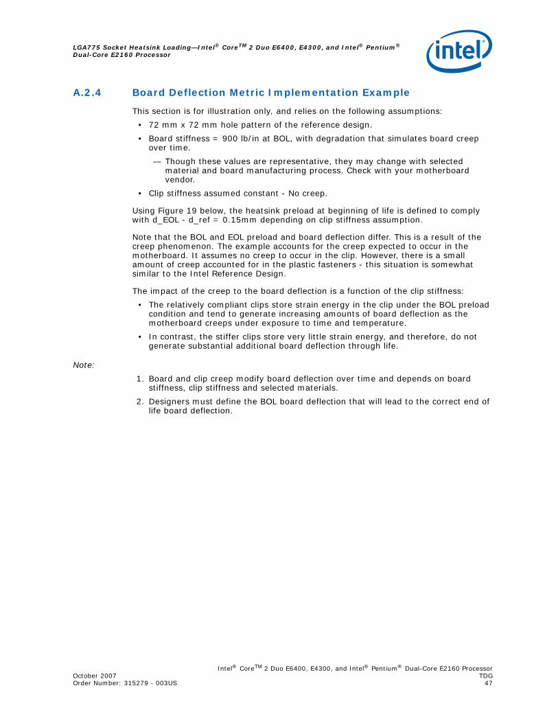
Intel® CoreTM 2 Duo E6400, E4300, and Intel® Pentium® Dual-Core E2160 ProcessorOctober 2007 TDGOrder Number: 315279 - 003US 47
LGA775 Socket Heatsink Loading—Intel® CoreTM 2 Duo E6400, E4300, and Intel® Pentium® Dual-Core E2160 Processor
A.2.4 Board Deflection Metric Implementation Example
This section is for illustration only, and relies on the following assumptions:
• 72 mm x 72 mm hole pattern of the reference design.
• Board stiffness = 900 lb/in at BOL, with degradation that simulates board creep over time.
— Though these values are representative, they may change with selected material and board manufacturing process. Check with your motherboard vendor.
• Clip stiffness assumed constant - No creep.
Using Figure 19 below, the heatsink preload at beginning of life is defined to comply with d_EOL - d_ref = 0.15mm depending on clip stiffness assumption.
Note that the BOL and EOL preload and board deflection differ. This is a result of the creep phenomenon. The example accounts for the creep expected to occur in the motherboard. It assumes no creep to occur in the clip. However, there is a small amount of creep accounted for in the plastic fasteners - this situation is somewhat similar to the Intel Reference Design.
The impact of the creep to the board deflection is a function of the clip stiffness:
• The relatively compliant clips store strain energy in the clip under the BOL preload condition and tend to generate increasing amounts of board deflection as the motherboard creeps under exposure to time and temperature.
• In contrast, the stiffer clips store very little strain energy, and therefore, do not generate substantial additional board deflection through life.
Note:
1. Board and clip creep modify board deflection over time and depends on board stiffness, clip stiffness and selected materials.
2. Designers must define the BOL board deflection that will lead to the correct end of life board deflection.
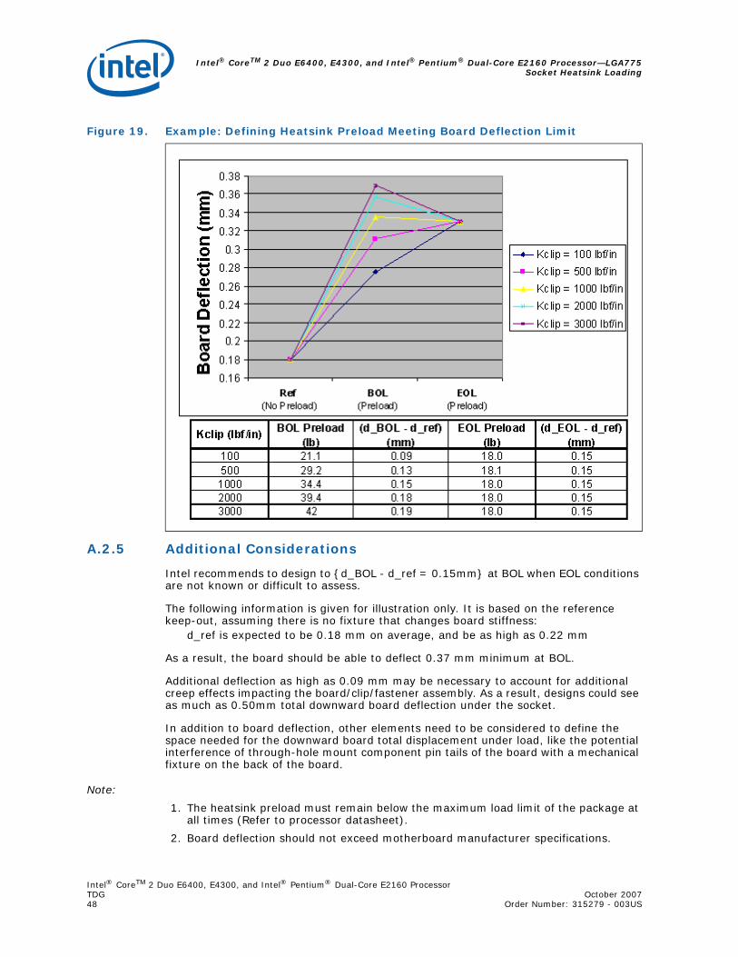
Intel® CoreTM 2 Duo E6400, E4300, and Intel® Pentium® Dual-Core E2160 Processor—LGA775Socket Heatsink Loading
Intel® CoreTM 2 Duo E6400, E4300, and Intel® Pentium® Dual-Core E2160 ProcessorTDG October 200748 Order Number: 315279 - 003US
A.2.5 Additional Considerations
Intel recommends to design to {d_BOL - d_ref = 0.15mm} at BOL when EOL conditions are not known or difficult to assess.
The following information is given for illustration only. It is based on the reference keep-out, assuming there is no fixture that changes board stiffness:
d_ref is expected to be 0.18 mm on average, and be as high as 0.22 mm
As a result, the board should be able to deflect 0.37 mm minimum at BOL.
Additional deflection as high as 0.09 mm may be necessary to account for additional creep effects impacting the board/clip/fastener assembly. As a result, designs could see as much as 0.50mm total downward board deflection under the socket.
In addition to board deflection, other elements need to be considered to define the space needed for the downward board total displacement under load, like the potential interference of through-hole mount component pin tails of the board with a mechanical fixture on the back of the board.
Note:
1. The heatsink preload must remain below the maximum load limit of the package at all times (Refer to processor datasheet).
2. Board deflection should not exceed motherboard manufacturer specifications.
Figure 19. Example: Defining Heatsink Preload Meeting Board Deflection Limit
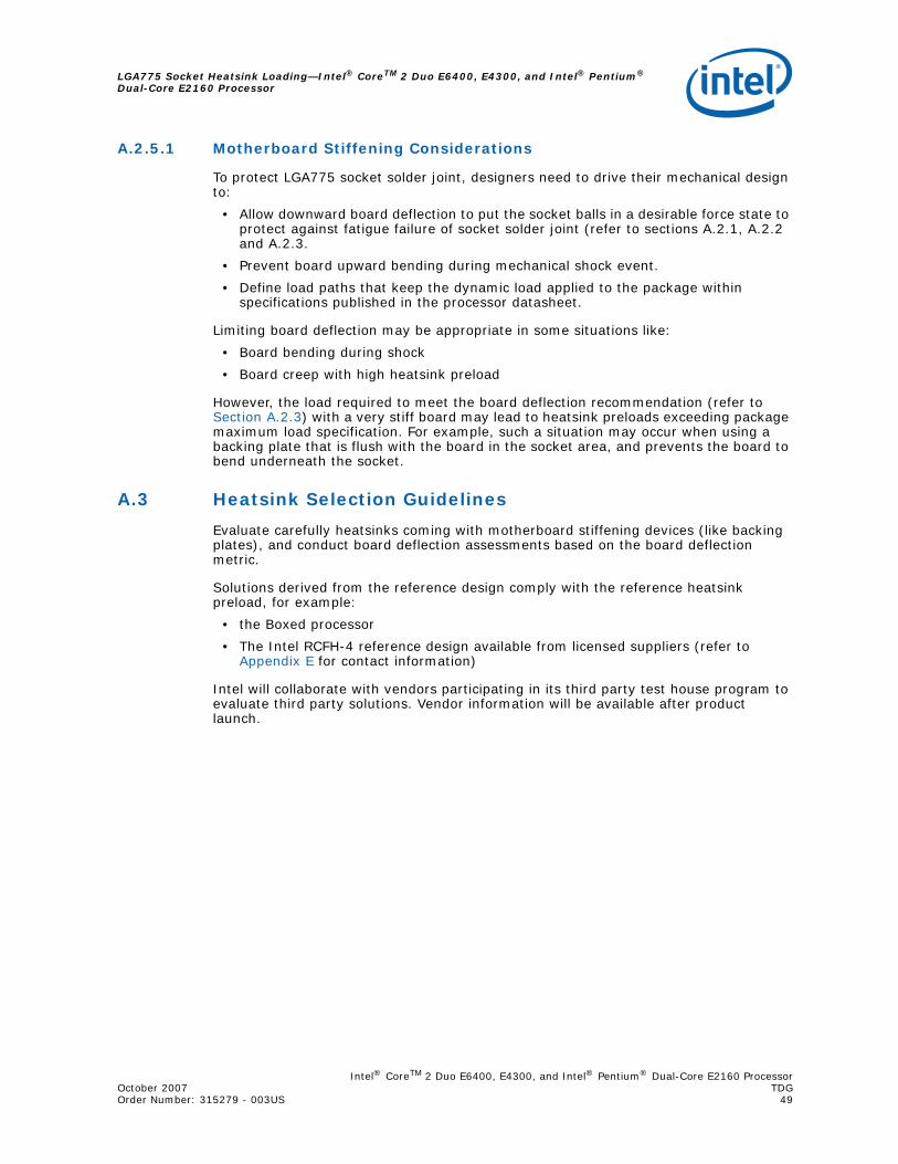
Intel® CoreTM 2 Duo E6400, E4300, and Intel® Pentium® Dual-Core E2160 ProcessorOctober 2007 TDGOrder Number: 315279 - 003US 49
LGA775 Socket Heatsink Loading—Intel® CoreTM 2 Duo E6400, E4300, and Intel® Pentium® Dual-Core E2160 Processor
A.2.5.1 Motherboard Stiffening Considerations
To protect LGA775 socket solder joint, designers need to drive their mechanical design to:
• Allow downward board deflection to put the socket balls in a desirable force state to protect against fatigue failure of socket solder joint (refer to sections A.2.1, A.2.2 and A.2.3.
• Prevent board upward bending during mechanical shock event.
• Define load paths that keep the dynamic load applied to the package within specifications published in the processor datasheet.
Limiting board deflection may be appropriate in some situations like:
• Board bending during shock
• Board creep with high heatsink preload
However, the load required to meet the board deflection recommendation (refer to Section A.2.3) with a very stiff board may lead to heatsink preloads exceeding package maximum load specification. For example, such a situation may occur when using a backing plate that is flush with the board in the socket area, and prevents the board to bend underneath the socket.
A.3 Heatsink Selection Guidelines
Evaluate carefully heatsinks coming with motherboard stiffening devices (like backing plates), and conduct board deflection assessments based on the board deflection metric.
Solutions derived from the reference design comply with the reference heatsink preload, for example:
• the Boxed processor
• The Intel RCFH-4 reference design available from licensed suppliers (refer to Appendix E for contact information)
Intel will collaborate with vendors participating in its third party test house program to evaluate third party solutions. Vendor information will be available after product launch.
Intel® CoreTM 2 Duo E6400, E4300, and Intel® Pentium® Dual-Core E2160 Processor—ThermalInterface Management
Intel® CoreTM 2 Duo E6400, E4300, and Intel® Pentium® Dual-Core E2160 ProcessorTDG October 200750 Order Number: 315279 -003US
Appendix B Thermal Interface Management
To optimize a heatsink design, it is important to understand the impact of factors related to the interface between the processor and the heatsink base. Specifically, the bond line thickness, interface material area and interface material thermal conductivity should be managed to realize the most effective thermal solution.
B.1 Bond Line Management
Any gap between the processor integrated heat spreader (IHS) and the heatsink base degrades thermal solution performance. The larger the gap between the two surfaces, the greater the thermal resistance. The thickness of the gap is determined by the flatness and roughness of both the heatsink base and the integrated heat spreader, plus the thickness of the thermal interface material (for example thermal grease) used between these two surfaces and the clamping force applied by the heatsink attach clip(s).
B.2 Interface Material Area
The size of the contact area between the processor and the heatsink base will impact the thermal resistance. However, there is a point of diminishing returns. Unrestrained incremental increases in thermal interface material area do not translate to a measurable improvement in thermal performance.
B.3 Interface Material Performance
Two factors impact the performance of the interface material between the processor and the heatsink base:
• Thermal resistance of the material
• Wetting/filling characteristics of the material
Thermal resistance is a description of the ability of the thermal interface material to transfer heat from one surface to another. The higher the thermal resistance, the less efficient the interface material is at transferring heat. The thermal resistance of the interface material has a significant impact on the thermal performance of the overall thermal solution. The higher the thermal resistance, the larger the temperature drop is across the interface and the more efficient the thermal solution (heatsink, fan) must be to achieve the desired cooling.
The wetting or filling characteristic of the thermal interface material is its ability, under the load applied by the heatsink retention mechanism, to spread and fill the gap between the processor and the heatsink. Since air is an extremely poor thermal conductor, the more completely the interface material fills the gaps, the lower the temperature drops across the interface. In this case, thermal interface material area also becomes significant; the larger the desired thermal interface material area, the higher the force required to spread the thermal interface material.
Intel® CoreTM 2 Duo E6400, E4300, and Intel® Pentium® Dual-Core E2160 ProcessorOctober 2007 TDGOrder Number: 315279 - 003US 51
Case Temperature Reference Metrology—Intel® CoreTM 2 Duo E6400, E4300, and Intel® Pentium® Dual-Core E2160 Processor
Appendix C Case Temperature Reference Metrology
C.1 Objective and Scope
This appendix defines a reference procedure for attaching a thermocouple to the IHS of a 775-land LGA package for TC measurement. This procedure takes into account the specific features of the 775-land LGA package and of the LGA775 socket for which it is intended. The recommended equipment for the reference thermocouple installation, including tools and part numbers are also provided. In addition, a video that shows the process in real time - Thermocouple Attach Using Solder - Video CD-ROM - is available.
For information on case temperature reference setup, tool use, and approach, please refer to Intel® Core™2 Duo Processor and Intel® Pentium® Dual Core Processor Thermal and Mechanical Design Guidelines, Appendix D.
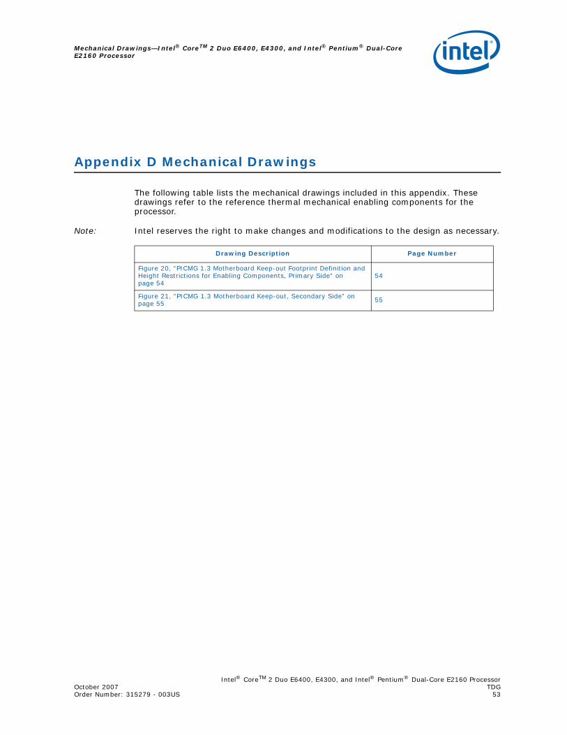
Intel® CoreTM 2 Duo E6400, E4300, and Intel® Pentium® Dual-Core E2160 ProcessorOctober 2007 TDGOrder Number: 315279 - 003US 53
Mechanical Drawings—Intel® CoreTM 2 Duo E6400, E4300, and Intel® Pentium® Dual-Core E2160 Processor
Appendix D Mechanical Drawings
The following table lists the mechanical drawings included in this appendix. These drawings refer to the reference thermal mechanical enabling components for the processor.
Note: Intel reserves the right to make changes and modifications to the design as necessary.
Drawing Description Page Number
Figure 20, “PICMG 1.3 Motherboard Keep-out Footprint Definition and Height Restrictions for Enabling Components, Primary Side” on page 54
54
Figure 21, “PICMG 1.3 Motherboard Keep-out, Secondary Side” on page 55 55
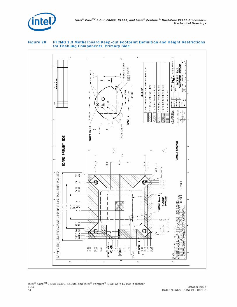
Intel® CoreTM 2 Duo E6400, E4300, and Intel® Pentium® Dual-Core E2160 Processor—Mechanical Drawings
Intel® CoreTM 2 Duo E6400, E4300, and Intel® Pentium® Dual-Core E2160 ProcessorTDG October 200754 Order Number: 315279 - 003US
Figure 20. PICMG 1.3 Motherboard Keep-out Footprint Definition and Height Restrictions for Enabling Components, Primary Side
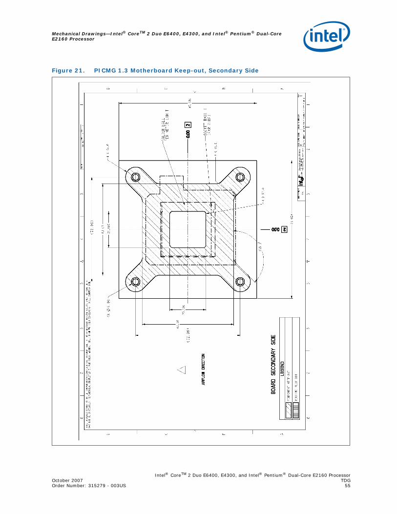
Intel® CoreTM 2 Duo E6400, E4300, and Intel® Pentium® Dual-Core E2160 ProcessorOctober 2007 TDGOrder Number: 315279 - 003US 55
Mechanical Drawings—Intel® CoreTM 2 Duo E6400, E4300, and Intel® Pentium® Dual-Core E2160 Processor
Figure 21. PICMG 1.3 Motherboard Keep-out, Secondary Side
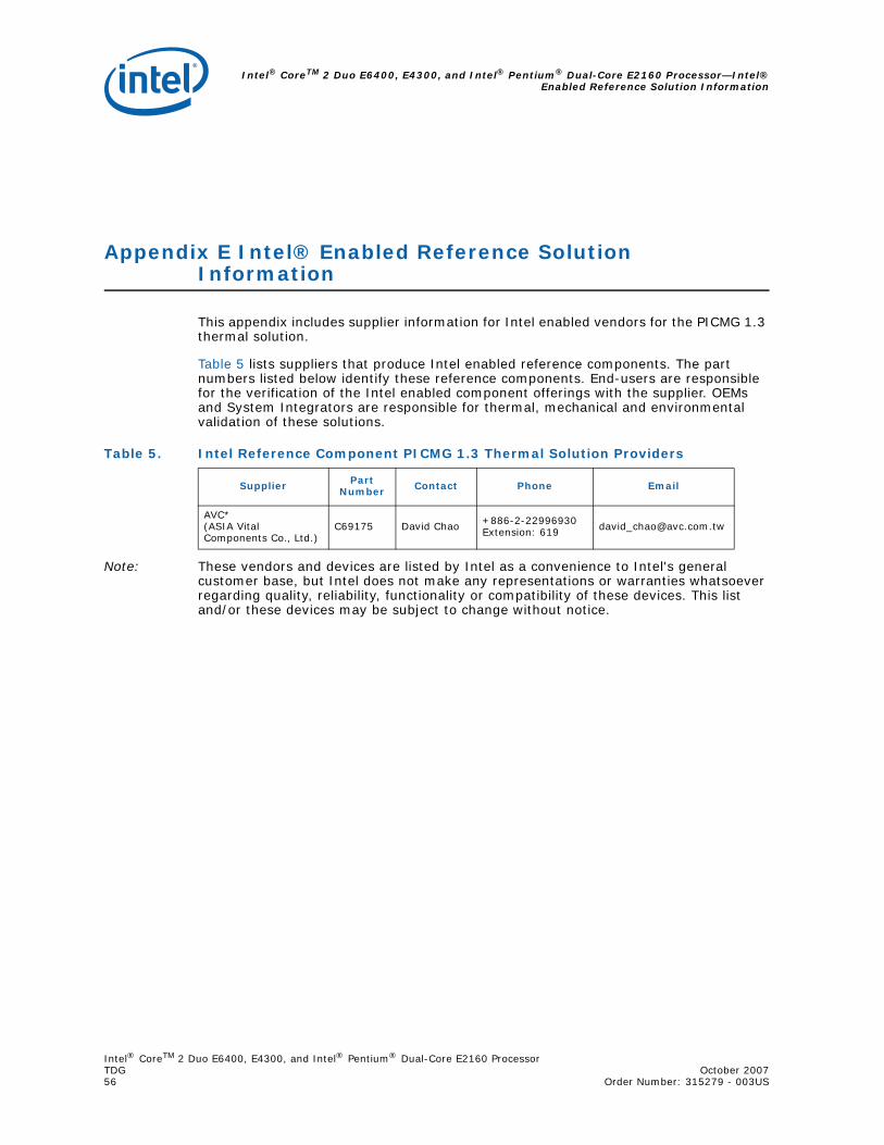
Intel® CoreTM 2 Duo E6400, E4300, and Intel® Pentium® Dual-Core E2160 Processor—Intel®Enabled Reference Solution Information
Intel® CoreTM 2 Duo E6400, E4300, and Intel® Pentium® Dual-Core E2160 ProcessorTDG October 200756 Order Number: 315279 - 003US
Appendix E Intel® Enabled Reference Solution Information
This appendix includes supplier information for Intel enabled vendors for the PICMG 1.3 thermal solution.
Table 5 lists suppliers that produce Intel enabled reference components. The part numbers listed below identify these reference components. End-users are responsible for the verification of the Intel enabled component offerings with the supplier. OEMs and System Integrators are responsible for thermal, mechanical and environmental validation of these solutions.
Note: These vendors and devices are listed by Intel as a convenience to Intel's general customer base, but Intel does not make any representations or warranties whatsoever regarding quality, reliability, functionality or compatibility of these devices. This list and/or these devices may be subject to change without notice.
Table 5. Intel Reference Component PICMG 1.3 Thermal Solution Providers
Supplier Part Number Contact Phone Email
AVC* (ASIA Vital Components Co., Ltd.)
C69175 David Chao +886-2-22996930 Extension: 619 [email protected]


![HOO SX2210 . gh Hâ& 'DÐ1ó!2 · p·.¢[ 'DÐpÉ! 2.8 GHz ¼`õ A]-' Wô Mz"GP¥F, Intel Pentium Core 2 Duo E4300 1¾AMD F #´JñLÂUýC®& p¸! l Microsoft Windows XP Service Pack](https://img.dokumen.tips/doc/110x75/5ed49f66c593a815a0496e24/hoo-sx2210-gh-h-d12-p-dp-28-ghz-a-w-mzgpf.jpg)


![uLtRAPORtátILES DELL LAtItuDE E4200 y E4300 · (802.11 a/g/n 2x2), Intel WiFi Link 5100 [802.11a/g/n (1x2)] Intel WiFi Link 5300 [802.11a/g/n (3x3)] Banda ancha móvil y GPS: Dell](https://img.dokumen.tips/doc/110x75/60426ebb8d68c918aa281026/ultraporttiles-dell-latitude-e4200-y-e4300-80211-agn-2x2-intel-wifi-link.jpg)