Embed Size (px)
Citation preview
Intel® Core™ i7 Processor Family forthe LGA2011-3 SocketThermal/Mechanical Specification and Design Guide (TMSDG) Supporting Desktop Intel® CoreTM i7-5960X Extreme EditionProcessor for the LGA2011-3 SocketSupporting Desktop Intel® CoreTM i7-59xx and i7-58xx ProcessorSeries for the LGA2011-3 Socket
August 2014
Order No.: 330842-001
By using this document, in addition to any agreements you have with Intel, you accept the terms set forth below.
You may not use or facilitate the use of this document in connection with any infringement or other legal analysis concerning Intel products describedherein. You agree to grant Intel a non-exclusive, royalty-free license to any patent claim thereafter drafted which includes subject matter disclosedherein.
INFORMATION IN THIS DOCUMENT IS PROVIDED IN CONNECTION WITH INTEL PRODUCTS. NO LICENSE, EXPRESS OR IMPLIED, BY ESTOPPEL OROTHERWISE, TO ANY INTELLECTUAL PROPERTY RIGHTS IS GRANTED BY THIS DOCUMENT. EXCEPT AS PROVIDED IN INTEL'S TERMS ANDCONDITIONS OF SALE FOR SUCH PRODUCTS, INTEL ASSUMES NO LIABILITY WHATSOEVER AND INTEL DISCLAIMS ANY EXPRESS OR IMPLIEDWARRANTY, RELATING TO SALE AND/OR USE OF INTEL PRODUCTS INCLUDING LIABILITY OR WARRANTIES RELATING TO FITNESS FOR APARTICULAR PURPOSE, MERCHANTABILITY, OR INFRINGEMENT OF ANY PATENT, COPYRIGHT OR OTHER INTELLECTUAL PROPERTY RIGHT.
A "Mission Critical Application" is any application in which failure of the Intel Product could result, directly or indirectly, in personal injury or death.SHOULD YOU PURCHASE OR USE INTEL'S PRODUCTS FOR ANY SUCH MISSION CRITICAL APPLICATION, YOU SHALL INDEMNIFY AND HOLD INTEL ANDITS SUBSIDIARIES, SUBCONTRACTORS AND AFFILIATES, AND THE DIRECTORS, OFFICERS, AND EMPLOYEES OF EACH, HARMLESS AGAINST ALLCLAIMS COSTS, DAMAGES, AND EXPENSES AND REASONABLE ATTORNEYS' FEES ARISING OUT OF, DIRECTLY OR INDIRECTLY, ANY CLAIM OFPRODUCT LIABILITY, PERSONAL INJURY, OR DEATH ARISING IN ANY WAY OUT OF SUCH MISSION CRITICAL APPLICATION, WHETHER OR NOT INTELOR ITS SUBCONTRACTOR WAS NEGLIGENT IN THE DESIGN, MANUFACTURE, OR WARNING OF THE INTEL PRODUCT OR ANY OF ITS PARTS.
Intel may make changes to specifications and product descriptions at any time, without notice. Designers must not rely on the absence orcharacteristics of any features or instructions marked "reserved" or "undefined". Intel reserves these for future definition and shall have noresponsibility whatsoever for conflicts or incompatibilities arising from future changes to them. The information here is subject to change withoutnotice. Do not finalize a design with this information.
The products described in this document may contain design defects or errors known as errata which may cause the product to deviate from publishedspecifications. Current characterized errata are available on request.
Contact your local Intel sales office or your distributor to obtain the latest specifications and before placing your product order.
Copies of documents which have an order number and are referenced in this document, or other Intel literature, may be obtained by calling1-800-548-4725, or go to: http://www.intel.com/design/literature.htm
Intel® Hyper-Threading Technology (Intel® HT Technology) is available on select Intel® Core™ processors. It requires an Intel® HT Technology enabledsystem. Consult your PC manufacturer. Performance will vary depending on the specific hardware and software used. Not available on Intel® Core™
i5-750. For more information including details on which processors support Intel® HT Technology, visit http://www.intel.com/info/hyperthreading.
Intel® High Definition Audio (Intel® HD Audio) requires an Intel® HD Audio enabled system. Consult your PC manufacturer for more information.Sound quality will depend on equipment and actual implementation. For more information about Intel® HD Audio, refer to http://www.intel.com/design/chipsets/hdaudio.htm.
Intel® 64 architecture requires a system with a 64-bit enabled processor, chipset, BIOS and software. Performance will vary depending on the specifichardware and software you use. Consult your PC manufacturer for more information. For more information, visit http://www.intel.com/content/www/us/en/architecture-and-technology/microarchitecture/intel-64-architecture-general.html.
Intel® Virtualization Technology (Intel® VT) requires a computer system with an enabled Intel® processor, BIOS, and virtual machine monitor (VMM).Functionality, performance or other benefits will vary depending on hardware and software configurations. Software applications may not becompatible with all operating systems. Consult your PC manufacturer. For more information, visit http://www.intel.com/go/virtualization.
Requires a system with Intel® Turbo Boost Technology. Intel Turbo Boost Technology and Intel Turbo Boost Technology 2.0 are only available on selectIntel® processors. Consult your PC manufacturer. Performance varies depending on hardware, software, and system configuration. For moreinformation, visit http://www.intel.com/go/turbo.
Intel, the Intel logo, and Intel Core are trademarks of Intel Corporation in the U.S. and/or other countries.
*Other names and brands may be claimed as the property of others.
Copyright © 2014, Intel Corporation. All rights reserved.
Intel® Core™ i7 Processor Family for the LGA2011-3 SocketThermal/Mechanical Specification and Design Guide (TMSDG) August 20142 Order No.: 330842-001
Revision History
Revision Number Description Date
001 Initial Release August 2014
Revision History—Processor
Intel® Core™ i7 Processor Family for the LGA2011-3 SocketAugust 2014 Thermal/Mechanical Specification and Design Guide (TMSDG)Order No.: 330842-001 3
Contents
Revision History..................................................................................................................3
1.0 Introduction................................................................................................................. 81.1 Reference Documents............................................................................................. 8
2.0 LGA2011-3 Socket Overview.........................................................................................92.1 Socket Components.............................................................................................. 102.2 Socket Land Pattern Guidance................................................................................ 142.3 Socket Loading Requirements.................................................................................16
2.3.1 Socket Loading Specifications.................................................................... 162.4 Socket Electrical Requirements............................................................................... 17
3.0 Independent Loading Mechanism (ILM) Specifications............................................... 183.1 ILM Load Specifications......................................................................................... 193.2 ILM Keepout Zones (KOZ)......................................................................................203.3 Independent Loading Mechanism (ILM)....................................................................203.4 ILM Mechanical Design Considerations and Recommendations.....................................213.5 ILM Features........................................................................................................ 213.6 Intel® ILM Reference Designs................................................................................. 23
3.6.1 ILM.........................................................................................................233.7 ILM Cover............................................................................................................253.8 ILM Allowable Board Thickness............................................................................... 26
4.0 Processor Thermal Specifications and Features......................................................... 274.1 Tcase and DTS-Based Thermal Specification Implementation........................................27
4.1.1 Margin to Thermal Specification (M)............................................................ 274.2 Processor Thermal Features................................................................................... 29
4.2.1 Adaptive Thermal Monitor.......................................................................... 294.2.2 On-Demand Mode..................................................................................... 304.2.3 PROCHOT_N Signal................................................................................... 304.2.4 THERMTRIP_N Signal.................................................................................304.2.5 Absolute Processor Temperature................................................................. 31
4.3 Processor Thermal Specifications............................................................................ 314.3.1 Thermal Specifications...............................................................................314.3.2 TCASE and DTS Based Thermal Specifications.................................................324.3.3 Processor Thermal Specifications.................................................................334.3.4 Thermal Metrology.................................................................................... 33
5.0 Processor Thermal Solutions.......................................................................................355.1 Heatsink Design Considerations.............................................................................. 355.2 Thermal Design Guidelines.....................................................................................36
5.2.1 Intel® Turbo Boost Technology................................................................... 365.2.2 Thermal Excursion Power........................................................................... 365.2.3 Thermal Characterization Parameters.......................................................... 36
5.3 Thermal Interface Material (TIM) Considerations....................................................... 385.4 Mechanical Recommendations and Targets............................................................... 38
5.4.1 Processor / Socket Stackup Height.............................................................. 385.4.2 Processor Heatsink Mechanical Targets........................................................ 40
5.5 Heatsink Mechanical and Structural Considerations....................................................41
Processor—Contents
Intel® Core™ i7 Processor Family for the LGA2011-3 SocketThermal/Mechanical Specification and Design Guide (TMSDG) August 20144 Order No.: 330842-001

6.0 Processor Mechanical Specifications........................................................................... 426.1 Package Loading Specifications...............................................................................426.2 Processor Mass Specification.................................................................................. 436.3 Processor Materials............................................................................................... 436.4 Processor Markings............................................................................................... 436.5 Package Handling Guidelines.................................................................................. 44
7.0 Quality Reliability and Ecological Requirements..........................................................467.1 Use Conditions..................................................................................................... 467.2 Intel Reference Component Validation..................................................................... 47
7.2.1 Board Functional Test Sequence..................................................................477.2.2 Post-Test Pass Criteria Examples.................................................................477.2.3 Recommended BIOS/Processor/Memory Test Procedures................................48
7.3 Material and Recycling Requirements.......................................................................48
Appendix A Component Suppliers..................................................................................... 50
Appendix B Mechanical Drawings......................................................................................51B.1 Package Mechanical Drawing Page 1........................................................................52B.2 Package Mechanical Drawing Page 2........................................................................53B.3 ILM Backplate Keep Out Zone.................................................................................54B.4 ILM Mounting Hole Keep Out Zone.......................................................................... 55B.5 ILM Keep Out Zone............................................................................................... 56B.6 3D Keep Out Zone................................................................................................ 57
Contents—Processor
Intel® Core™ i7 Processor Family for the LGA2011-3 SocketAugust 2014 Thermal/Mechanical Specification and Design Guide (TMSDG)Order No.: 330842-001 5
Figures1 Hexagonal Array in LGA2011-3................................................................................... 92 Socket with Labeled Features.................................................................................... 103 Contact Wiping Direction.......................................................................................... 114 Contact Tip Offset with Respect to Solder Ball..............................................................125 Processor Socket Stack Up........................................................................................136 Pick and Place Cover with Labeled Features.................................................................137 PnP Cover and Socket Assembly................................................................................ 148 Socket 2011-3 Land Pattern......................................................................................159 Processor Stack.......................................................................................................1810 ILM Load Plate........................................................................................................ 2211 ILM Backplate......................................................................................................... 2312 Exploded ILM.......................................................................................................... 2413 Assembled ILM........................................................................................................2514 ILM cover............................................................................................................... 2615 Margin to Thermal Spec (M)......................................................................................2816 Typical Thermal Profile Graph (Illustration Only).......................................................... 3217 Case Temperature (TCASE) Measurement Location........................................................ 3418 Thermal Characterization Parameters......................................................................... 3719 Integrated Stack Up Height.......................................................................................3920 Available Cooling Area for IHS...................................................................................4021 Processor Package Assembly Sketch...........................................................................4222 Package Labeling.....................................................................................................4423 Package Mechanical Drawing Page 1.......................................................................... 5224 Package Mechanical Drawing Page 2.......................................................................... 5325 ILM Backplate Keep Out Zone................................................................................... 5426 ILM Mounting Hole Keep Out Zone............................................................................. 5527 ILM Keep Out Zone..................................................................................................5628 3D Keep Out Zone................................................................................................... 57
Processor—Figures
Intel® Core™ i7 Processor Family for the LGA2011-3 SocketThermal/Mechanical Specification and Design Guide (TMSDG) August 20146 Order No.: 330842-001
Tables1 LGA2011-3 Socket Attributes...................................................................................... 92 PIN Count By Pad Definition......................................................................................163 Socket Load Values..................................................................................................164 LGA 2011-3 Socket Electrical Requirements................................................................ 175 LGA 2011-3 Maximum Allowable Loads.......................................................................196 LGA 2011-3 Minimum Allowable Loads....................................................................... 197 LGA 2011-3 Minimum End of Life Loads......................................................................208 LGA 2011-3 ILM General Keepout Dimensions ............................................................ 209 ILM Component Thickness and materials.................................................................... 2510 DTS 2.0 Margin From PECI........................................................................................2811 DTS 2.0 Margin From Processor Register: CSR for PACKAGE_THERM_MARGIN ................ 2912 Target Stackup Heights From Top of Board to Top of IHS.............................................. 3913 Available Cooling Area for IHS...................................................................................3914 Heatsink Mechanical Targets..................................................................................... 4015 Processor Loading Specifications................................................................................4316 Processor Materials..................................................................................................4317 Load Limits for Package Handling...............................................................................4518 Intel® Reference or Collaboration Thermal Solutions..................................................... 5019 LGA2011-3 Socket and ILM Components ....................................................................5020 List of Mechanical Drawings...................................................................................... 51
Tables—Processor
Intel® Core™ i7 Processor Family for the LGA2011-3 SocketAugust 2014 Thermal/Mechanical Specification and Design Guide (TMSDG)Order No.: 330842-001 7
1.0 Introduction
This document provides specifications and guidelines for the design of thermal andmechanical solutions for Intel® Core™ i7 Processor Family for the LGA2011-3 Socket.The processors covered are listed in the Processor Datasheet, Volume 1 (seeReference Documents).
Note: When information in this document is applicable to all products this document will use'processor' or 'processors' to simplify this document.
The components and information described in this document include:
• Thermal profiles and other processor specifications and recommendations
• Processor Mechanical load limits
• Independent Loading Mechanism (ILM) specifications and recommendations
• Heatsink recommendations
• Reference designs for processor thermal solution (heatsink) and associatedretention hardware
• Reference designs for the socket, ILM and associated back plate
The goals of this document are:
• To assist board and system thermal mechanical designers
• To assist designers and suppliers of processor heatsinks
Reference Documents
Document Title Document Number
Intel® CoreTM i7 Processor Family for the LGA2011-3 Socket Datasheet -Volume 1 of 2
330839
Intel® CoreTM i7 Processor Family for the LGA2011-3 Socket Datasheet -Volume 2 of 2
330840
1.1
Processor—Introduction
Intel® Core™ i7 Processor Family for the LGA2011-3 SocketThermal/Mechanical Specification and Design Guide (TMSDG) August 20148 Order No.: 330842-001
2.0 LGA2011-3 Socket Overview
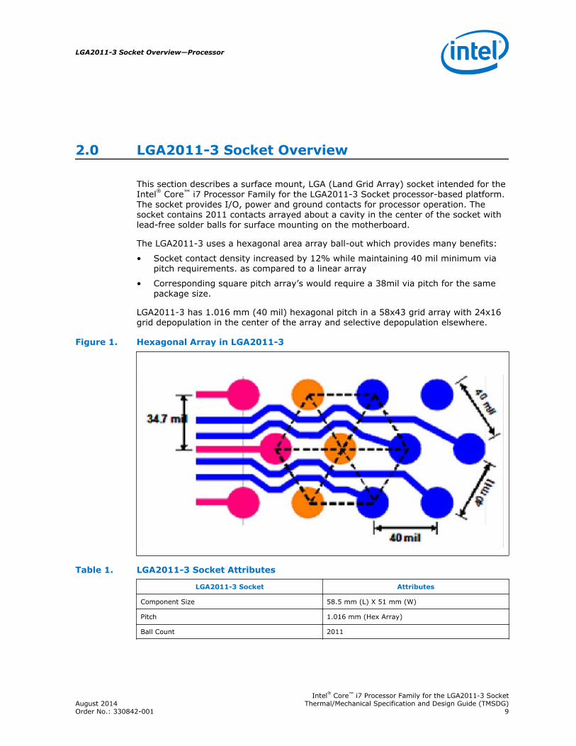
This section describes a surface mount, LGA (Land Grid Array) socket intended for theIntel® Core™ i7 Processor Family for the LGA2011-3 Socket processor-based platform.The socket provides I/O, power and ground contacts for processor operation. Thesocket contains 2011 contacts arrayed about a cavity in the center of the socket withlead-free solder balls for surface mounting on the motherboard.
The LGA2011-3 uses a hexagonal area array ball-out which provides many benefits:
• Socket contact density increased by 12% while maintaining 40 mil minimum viapitch requirements. as compared to a linear array
• Corresponding square pitch array’s would require a 38mil via pitch for the samepackage size.
LGA2011-3 has 1.016 mm (40 mil) hexagonal pitch in a 58x43 grid array with 24x16grid depopulation in the center of the array and selective depopulation elsewhere.
Figure 1. Hexagonal Array in LGA2011-3
Table 1. LGA2011-3 Socket Attributes
LGA2011-3 Socket Attributes
Component Size 58.5 mm (L) X 51 mm (W)
Pitch 1.016 mm (Hex Array)
Ball Count 2011
LGA2011-3 Socket Overview—Processor
Intel® Core™ i7 Processor Family for the LGA2011-3 SocketAugust 2014 Thermal/Mechanical Specification and Design Guide (TMSDG)Order No.: 330842-001 9

The socket must be compatible with the package (processor) and the IndependentLoading Mechanism (ILM). Internal keying posts ensure socket processorcompatibility. An external socket key ensures ILM and socket compatibility. The ILMreference design includes a back plate; an integral feature for uniform loading on thesocket solder joints and contacts.
Socket Components
The socket has two main components, the socket body: composed of a housing solderballs, and processor contacts, and Pick and Place (PnP) cover. The socket is deliveredas a single integral assembly. Below are descriptions of the integral parts of thesocket.
Socket Body Housing
The housing material is thermoplastic or equivalent with UL 94 V-0 flame ratingcapable of withstanding 260°C for 40 seconds (typical reflow/rework). The socketcoefficient of thermal expansion (in the XY plane), and creep properties, are such thatthe integrity of the socket is maintained for the environmental conditions listed in theTMSDG.
The color of the housing will be dark as compared to the solder balls to provide thecontrast needed for pick and place vision systems. A labeled representation of thesocket can be seen in the figure below.
Figure 2. Socket with Labeled Features
Solder Balls
A total of 2011 solder balls corresponding to the contacts are on the bottom of thesocket for surface mounting with the motherboard.
The socket has the following solder ball material:
2.1
Processor—LGA2011-3 Socket Overview
Intel® Core™ i7 Processor Family for the LGA2011-3 SocketThermal/Mechanical Specification and Design Guide (TMSDG) August 201410 Order No.: 330842-001
• Lead free SAC305 (SnAgCu) solder alloy with a silver (Ag) content 3%, copper(Cu) 0.5%, tin (Sn) 96.5% and a melting temperature of approximately 217°C.The immersion silver (ImAg) motherboard surface finish and solder paste alloymust be compatible with the SAC305 alloy solder paste.
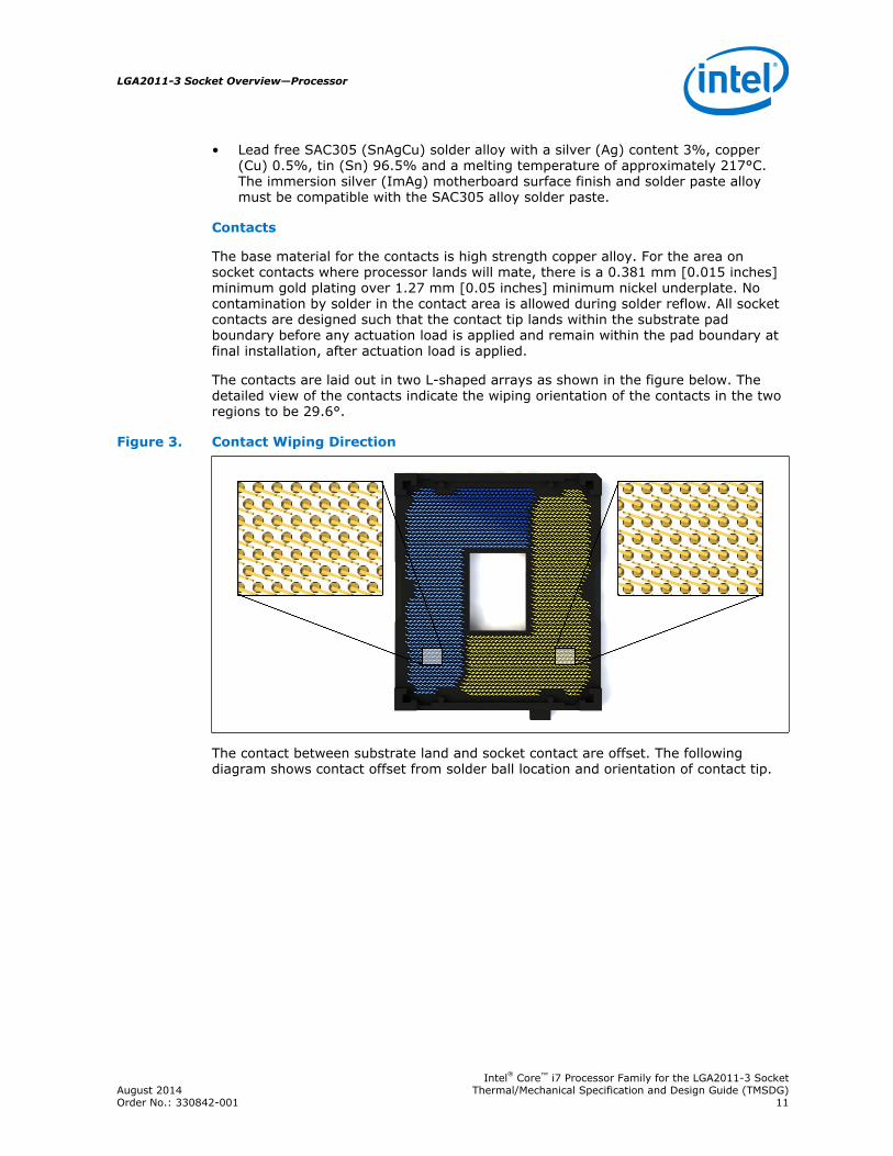
Contacts
The base material for the contacts is high strength copper alloy. For the area onsocket contacts where processor lands will mate, there is a 0.381 mm [0.015 inches]minimum gold plating over 1.27 mm [0.05 inches] minimum nickel underplate. Nocontamination by solder in the contact area is allowed during solder reflow. All socketcontacts are designed such that the contact tip lands within the substrate padboundary before any actuation load is applied and remain within the pad boundary atfinal installation, after actuation load is applied.
The contacts are laid out in two L-shaped arrays as shown in the figure below. Thedetailed view of the contacts indicate the wiping orientation of the contacts in the tworegions to be 29.6°.
Figure 3. Contact Wiping Direction
The contact between substrate land and socket contact are offset. The followingdiagram shows contact offset from solder ball location and orientation of contact tip.
LGA2011-3 Socket Overview—Processor
Intel® Core™ i7 Processor Family for the LGA2011-3 SocketAugust 2014 Thermal/Mechanical Specification and Design Guide (TMSDG)Order No.: 330842-001 11
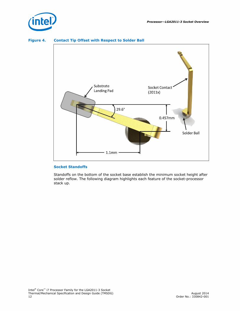
Figure 4. Contact Tip Offset with Respect to Solder Ball
Socket Standoffs
Standoffs on the bottom of the socket base establish the minimum socket height aftersolder reflow. The following diagram highlights each feature of the socket-processorstack up.
Processor—LGA2011-3 Socket Overview
Intel® Core™ i7 Processor Family for the LGA2011-3 SocketThermal/Mechanical Specification and Design Guide (TMSDG) August 201412 Order No.: 330842-001
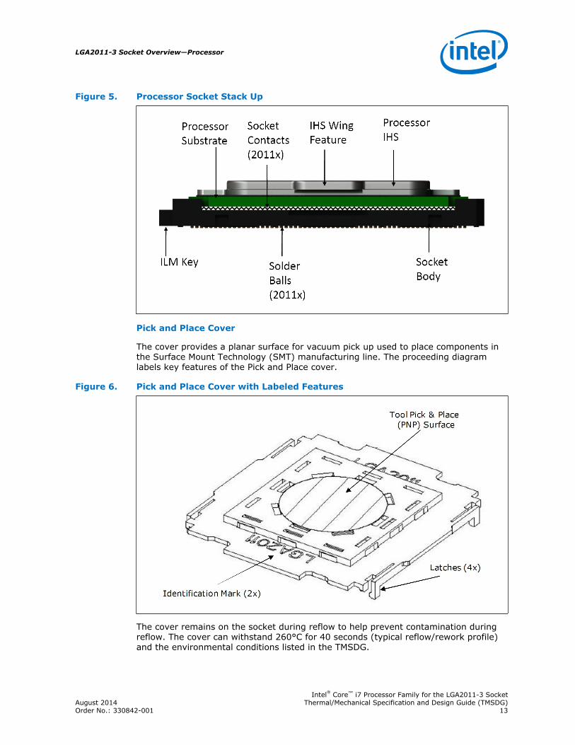
Figure 5. Processor Socket Stack Up
Pick and Place Cover
The cover provides a planar surface for vacuum pick up used to place components inthe Surface Mount Technology (SMT) manufacturing line. The proceeding diagramlabels key features of the Pick and Place cover.
Figure 6. Pick and Place Cover with Labeled Features
The cover remains on the socket during reflow to help prevent contamination duringreflow. The cover can withstand 260°C for 40 seconds (typical reflow/rework profile)and the environmental conditions listed in the TMSDG.
LGA2011-3 Socket Overview—Processor
Intel® Core™ i7 Processor Family for the LGA2011-3 SocketAugust 2014 Thermal/Mechanical Specification and Design Guide (TMSDG)Order No.: 330842-001 13

The following figure diagrams the PnP and socket assembly. To reduce risk of damageto socket contacts the pick and place (PnP) cover remains on the socket during ILMinstallation.
Figure 7. PnP Cover and Socket Assembly
Once the ILM with its cover is installed Intel is recommending the PnP cover beremoved to help prevent damage to the socket contacts. To reduce the risk of bentcontacts the PnP Cover and ILM Cover were designed to not be compatible. Coverscan be removed without tools.
The pick and place covers are designed to be interchangeable between socketsuppliers.
Socket Land Pattern Guidance
The land pattern guidance provided in this section applies to printed circuit boarddesign. Recommendation for Printed Circuit Board (PCB) Land Patterns is to ensuresolder joint reliability during dynamic stresses, often encountered during shipping andhandling and hence to increase socket reliability.
LGA 2011-3 Land Pattern
The land pattern for the LGA2011-3 socket is 40 mils hexagonal array see thefollowing figure for detailed location and land pattern type.
2.2
Processor—LGA2011-3 Socket Overview
Intel® Core™ i7 Processor Family for the LGA2011-3 SocketThermal/Mechanical Specification and Design Guide (TMSDG) August 201414 Order No.: 330842-001
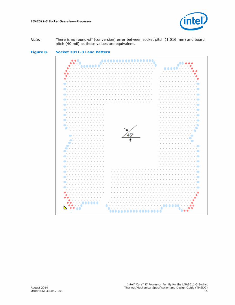
Note: There is no round-off (conversion) error between socket pitch (1.016 mm) and boardpitch (40 mil) as these values are equivalent.
Figure 8. Socket 2011-3 Land Pattern
LGA2011-3 Socket Overview—Processor
Intel® Core™ i7 Processor Family for the LGA2011-3 SocketAugust 2014 Thermal/Mechanical Specification and Design Guide (TMSDG)Order No.: 330842-001 15
Table 2. PIN Count By Pad Definition
Pad Definition / Padstack Color Quantity
20 X 17 Oblong Partially SMD / O17X20 RED Pins 43
20 X 17 Oblong Partially SMD / O17X20 LIGHT BLUE Pins 123
17 mil Ø MD / C17 GREY Pins 1845
Notes: 1. RED Pins: Corner nCTF pads (43 total) are all designed as 20 X 17 mil oblong partiallysoldermask defined pads with an SRO of 17+/-1mil Ø (shown below). The long axis of the pad isoriented at 45° from the center of the socket. All nCTF pads require thick traces ideally orientedat 45° toward the package corner.
2. LIGHT BLUE Pins: Edge CTF pads (total) are all designed as 20 X 17 mil oblong partiallysoldermask defined pads with an SRO of 17+/-1mil Ø (shown below). The long axis of the pad isoriented at 90° to the socket edge.
3. GREY Pins: Critical to function pins are all designed as 17 mil circular MD (Metal Defined) pads.
Socket Loading Requirements
The socket must meet the mechanical loading and strain requirements outlined in thetable below. All dynamic requirements are under room temperature conditions whileall static requirements are under product use condition temperature. Specifically, ILMand HS load range may vary for different LGA 2011 derivatives (e.g. 2011-0, 2011-1)due to the package form factor, and the design of loading mechanism and thermalsolution (e.g., HS mass).
Socket Loading Specifications
The table below provides load specifications for the socket. These mechanical limitsshould not be exceeded during component assembly, mechanical stress testing, orstandard drop and shipping conditions. All dynamic requirements are under roomtemperature conditions while all static requirements are under 100 °C conditions.
Table 3. Socket Load Values
Parameter Load Limits,SI Units
Load Limits,Imperial Units
Definition
Min Max Min Max
Static Compressiveper Contact
15 (gf) 38 (gf) 0.53(ozf)
1.34 (ozf) The compressive load applied by the package on theLGA contacts to meet electrical performance. Thiscondition must be satisfied throughout the life of theproduct
Static Compressive(ILM)
445 (N) 712 (N) 100 (lbf) 160 (lbf) The total load applied by the enabling mechanism ontothe socket as transferred through the package, contactsand socket seating plane.
Static CompressiveBeginning of Life(HS)
222 (N) 400 (N) 50 (lbf) 90 (lbf) The total load applied by the heatsink mechanism ontothe socket as transferred through the package, contactsand socket seating plane. Measured at Beginning of Life
Static CompressiveEnd of Life(HS)
178 (N) 400 (N) 40 (lbf) 90 (lbf) The total load applied by the heatsink mechanism ontothe socket as transferred through the package, contactsand socket seating plane. Measured at End of Life
continued...
2.3
2.3.1
Processor—LGA2011-3 Socket Overview
Intel® Core™ i7 Processor Family for the LGA2011-3 SocketThermal/Mechanical Specification and Design Guide (TMSDG) August 201416 Order No.: 330842-001
Parameter Load Limits,SI Units
Load Limits,Imperial Units
Definition
Min Max Min Max
Static TotalCompressive
667 (N) 1068 (N ) 150 (lbf) 240 (lbf) The total load applied by enabling mechanism and heatsink onto the socket as transferred through thepackage, contacts and socket seating plane.
DynamicCompressive
NA 588 (N) NA 132 (lbf) Quasi-static equivalent compressive load applied duringthe mechanical shock from heatsink, calculated using areference 600g heatsink with a 25G shock input and anamplification factor of 3 (600g x 25G x 3 =441N=99lbf). This specification can have flexibility in specificvalues, but the ultimate product of mass timesacceleration should not exceed this value. Intelreference system shock requirement for this productfamily is 25G input as measured at the chassismounting location.
Board TransientBend Strain
NA 500 (ue)for 62(mil);400 (ue)for 100(mil)
NA 500 (ue)for 62(mil);400 (ue)for 100(mil)
This is the strain on boards near to socket BGA cornersduring transient loading events through manufacturingflow or testing. The test guidance can be found in BoardFlexure Initiative (BFI) strain guidance from your localCQE.
Socket Electrical Requirements
LGA2011-3 socket electrical requirements are measured from the socket-seating planeof the processor to the component side of the socket PCB to which it is attached. Allspecifications are maximum values (unless otherwise stated) for a single socketcontact, but include effects of adjacent contacts where indicated.
Table 4. LGA 2011-3 Socket Electrical Requirements
Parameter Value Comment
Maximum Socket PartAverage Resistance(EOL @ 100°C)
25 milli-ohm This is the maximum allowable part average socket resistance allowed under all useconditions (EOL and 100°C). This is monitored by measuring the daisy chainresistance of all socket contacts in series across the socket and dividing by thenumber of contacts measured. The resulting value must be below 25 milli-ohm at alluse conditions (EOL) and elevated temperature (100°C).
Maximum SinglePin Resistance(mean + 4 sigma)(EOL @ 100°C)
38 milli-ohm This is the maximum validated single contact resistance on the socket under all useconditions (EOL) and at elevated temperature (100°C). This accounts for resistancevariation across the socket. While it is possible that a single contact may reach aresistance of 38 milli-ohm, the maximum socket part average resistance spec insuresthat all contacts averaged together will not be higher than 25 milli-ohm.
Dielectric WithstandVoltage
360 volts RMS
Insulation Resistance 800 milli-ohm
2.4
LGA2011-3 Socket Overview—Processor
Intel® Core™ i7 Processor Family for the LGA2011-3 SocketAugust 2014 Thermal/Mechanical Specification and Design Guide (TMSDG)Order No.: 330842-001 17
3.0 Independent Loading Mechanism (ILM)Specifications
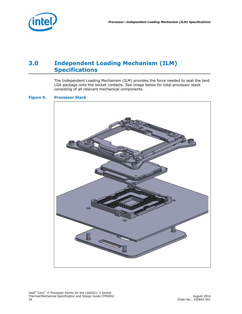
The Independent Loading Mechanism (ILM) provides the force needed to seat the landLGA package onto the socket contacts. See image below for total processor stackconsisting of all relevant mechanical components.
Figure 9. Processor Stack
Processor—Independent Loading Mechanism (ILM) Specifications
Intel® Core™ i7 Processor Family for the LGA2011-3 SocketThermal/Mechanical Specification and Design Guide (TMSDG) August 201418 Order No.: 330842-001
The ILM is physically separate from the socket body. The assembly of the ILM isexpected to occur after attaching the socket to the board. The exact assembly locationis dependent on manufacturing preference and test flow.
The mechanical design of the ILM is a key contributor to the overall functionality of thesocket. Intel performs detailed studies on integration of processor package, socketand ILM as a system. These studies directly impact the design of the ILM. The Intelreference ILM will be "built to print" from Intel controlled drawings. Intel recommendsusing the Intel Reference ILM. Custom non-Intel ILM designs do not benefit fromIntel's detailed studies and may not incorporate critical design parameters.
The ILM has two critical functions: evenly deliver and distribute the force to seat theprocessor onto the socket contacts and ultimately through the socket solder joints.Another purpose of ILM is to ensure electrical integrity/performance of the socket andpackage.
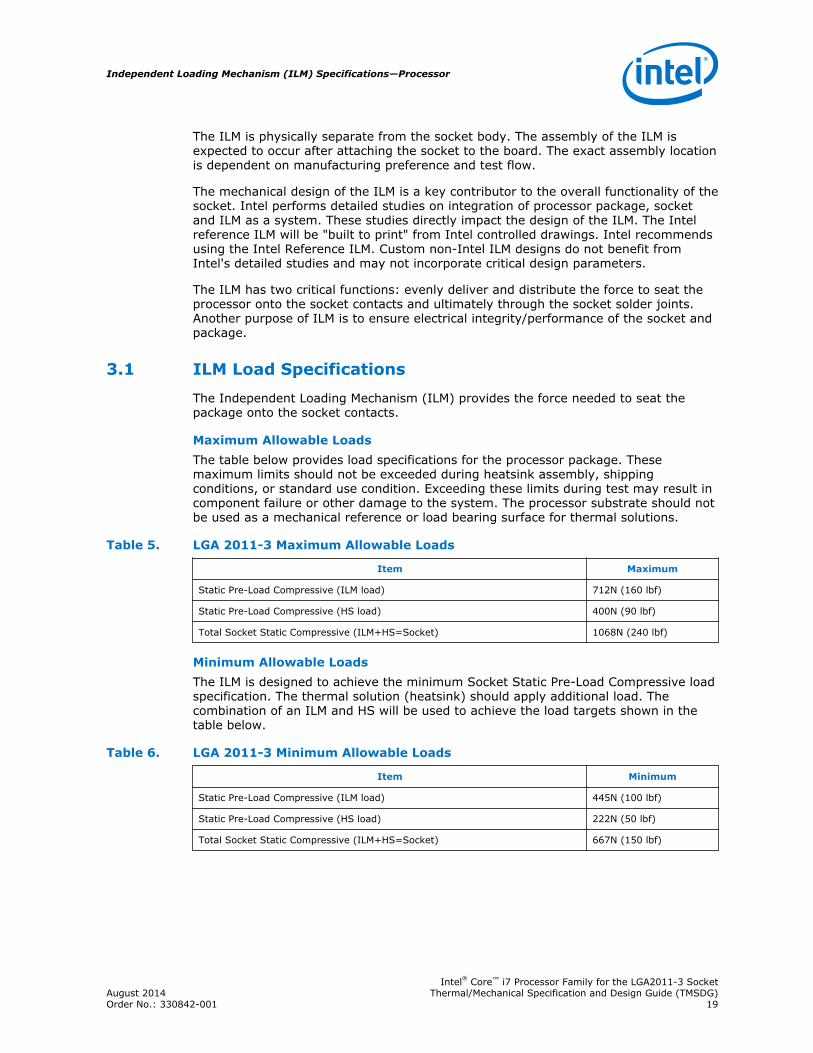
ILM Load Specifications
The Independent Loading Mechanism (ILM) provides the force needed to seat thepackage onto the socket contacts.
Maximum Allowable LoadsThe table below provides load specifications for the processor package. Thesemaximum limits should not be exceeded during heatsink assembly, shippingconditions, or standard use condition. Exceeding these limits during test may result incomponent failure or other damage to the system. The processor substrate should notbe used as a mechanical reference or load bearing surface for thermal solutions.
Table 5. LGA 2011-3 Maximum Allowable Loads
Item Maximum
Static Pre-Load Compressive (ILM load) 712N (160 lbf)
Static Pre-Load Compressive (HS load) 400N (90 lbf)
Total Socket Static Compressive (ILM+HS=Socket) 1068N (240 lbf)
Minimum Allowable LoadsThe ILM is designed to achieve the minimum Socket Static Pre-Load Compressive loadspecification. The thermal solution (heatsink) should apply additional load. Thecombination of an ILM and HS will be used to achieve the load targets shown in thetable below.
Table 6. LGA 2011-3 Minimum Allowable Loads
Item Minimum
Static Pre-Load Compressive (ILM load) 445N (100 lbf)
Static Pre-Load Compressive (HS load) 222N (50 lbf)
Total Socket Static Compressive (ILM+HS=Socket) 667N (150 lbf)
3.1
Independent Loading Mechanism (ILM) Specifications—Processor
Intel® Core™ i7 Processor Family for the LGA2011-3 SocketAugust 2014 Thermal/Mechanical Specification and Design Guide (TMSDG)Order No.: 330842-001 19
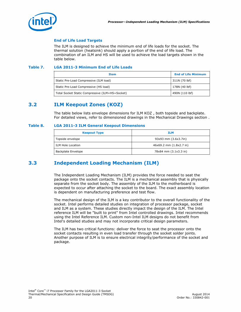
End of Life Load TargetsThe ILM is designed to achieve the minimum end of life loads for the socket. Thethermal solution (heatsink) should apply a portion of the end of life load. Thecombination of an ILM and HS will be used to achieve the load targets shown in thetable below.
Table 7. LGA 2011-3 Minimum End of Life Loads
Item End of Life Minimum
Static Pre-Load Compressive (ILM load) 311N (70 lbf)
Static Pre-Load Compressive (HS load) 178N (40 lbf)
Total Socket Static Compressive (ILM+HS=Socket) 490N (110 lbf)
ILM Keepout Zones (KOZ)
The table below lists envelope dimensions for ILM KOZ , both topside and backplate.For detailed views, refer to dimensioned drawings in the Mechanical Drawings section .
Table 8. LGA 2011-3 ILM General Keepout Dimensions
Keepout Type ILM
Topside envelope 93x93 mm (3.6x3.7in)
ILM Hole Location 46x69.2 mm (1.8x2.7 in)
Backplate Envelope 78x84 mm (3.1x3.3 in)
Independent Loading Mechanism (ILM)
The Independent Loading Mechanism (ILM) provides the force needed to seat thepackage onto the socket contacts. The ILM is a mechanical assembly that is physicallyseparate from the socket body. The assembly of the ILM to the motherboard isexpected to occur after attaching the socket to the board. The exact assembly locationis dependent on manufacturing preference and test flow.
The mechanical design of the ILM is a key contributor to the overall functionality of thesocket. Intel performs detailed studies on integration of processor package, socketand ILM as a system. These studies directly impact the design of the ILM. The Intelreference ILM will be "built to print" from Intel controlled drawings. Intel recommendsusing the Intel Reference ILM. Custom non-Intel ILM designs do not benefit fromIntel's detailed studies and may not incorporate critical design parameters.
The ILM has two critical functions: deliver the force to seat the processor onto thesocket contacts resulting in even load transfer through the socket solder joints.Another purpose of ILM is to ensure electrical integrity/performance of the socket andpackage.
3.2
3.3
Processor—Independent Loading Mechanism (ILM) Specifications
Intel® Core™ i7 Processor Family for the LGA2011-3 SocketThermal/Mechanical Specification and Design Guide (TMSDG) August 201420 Order No.: 330842-001
ILM Mechanical Design Considerations andRecommendations
An retention/loading mechanism must be designed to support the processor heatsinkand to ensure processor interface with the socket contact is maintained since thereare no features on the socket for direct attachment of the heatsink or retaining theprocessor. In addition to supporting the processor heatsink over the processor, thismechanism plays a significant role in the robustness of the system in which it isimplemented, in particular:
• Ensuring that thermal performance of the TIM applied between the IHS and theheatsink is achievable. TIMs, especially those based on phase change materials,are very sensitive to applied pressure: the higher the pressure, the better theinitial performance. TIMs such as thermal greases are not as sensitive to appliedpressure. Designs should consider the impact of shock and vibration events onTIM performance as well as possible decrease in applied pressure over time due topotential structural relaxation in enabled components.
• Ensuring that system electrical, thermal, and structural integrity is maintainedunder shock and vibration events. The mechanical requirements of the attachmechanism depend on the weight of the heatsink, as well as the level of shockand vibration that the system must support. The overall structural design of thebaseboard and system must be considered when designing the heatsink and ILMattach mechanism. Their design should provide a means for protecting the socketsolder joints as well as preventing package pullout from the socket.
• The load applied by the attachment mechanism and the heatsink must complywith the package specifications, along with the dynamic load added by themechanical shock and vibration requirements of the package and socket.
• Load induced onto the package and socket by the ILM may be influenced withheatsink installed. Determining the performance for any thermal/mechanicalsolution is the responsibility of the customer.
A potential mechanical solution for heavy heatsink is the use of a supportingmechanism such as a backer plate or the utilization of a direct attachment of theheatsink to the chassis pan. In these cases, the strength of the supporting componentcan be utilized rather than solely relying on the baseboard strength. In addition to thegeneral guidelines given above, contact with the baseboard surfaces should beminimized during installation in order to avoid any damage to the baseboard.
Placement of board-to-chassis mounting holes also impacts board deflection andresultant socket solder ball stress. Customers need to assess the shock for theirdesigns as heatsink retention (back plate), heatsink mass and chassis mounting holesmay vary.
ILM Features
The ILM is defined by four basic features
1. ILM Loadplate: Formed sheet metal that when closed applies four point loads ontothe IHS seating the processor into the socket
2. ILM Frame: Single piece or assembly that mounts to PCB board and provides thehinge locations for the levers the ILM frame also contains captive mounts forheatsink attach. An insulator is pre applied by the vendor to the bottom side ofthe ILM frame.
3.4
3.5
Independent Loading Mechanism (ILM) Specifications—Processor
Intel® Core™ i7 Processor Family for the LGA2011-3 SocketAugust 2014 Thermal/Mechanical Specification and Design Guide (TMSDG)Order No.: 330842-001 21
3. ILM Actuation levers: Formed loading levers designed to place equal force on bothends of the ILM load plate. Some of the load is passed through the socket body tothe board inducing a slight compression on the solder joints
4. ILM Backplate: A flat steel back plate with threaded studs to attach to the ILMframe. A clearance hole is located at the center of the plate to allow access to testpoints and backside capacitors. Two additional cut-outs on the backplate provideclearance for backside voltage regulator components. An insulator is pre appliedby the vendor to the side with the threaded studs.
Heatsink mounting studs on ILM frame allow for topside thermal solution attach to arigid structure. This eliminates the motherboard thickness dependency from theheatsink mechanical stackup. ILM assembly provides a clamping force between theILM frame, backplate and board, resulting in reduced board bending leading to highersolder joint reliability. ILM lever design provides an interlocking mechanism to ensureproper opening or closing sequence for the operator.
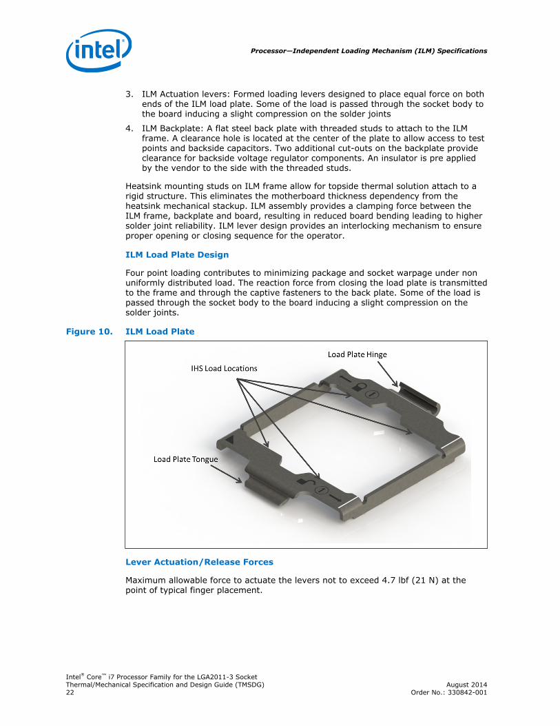
ILM Load Plate Design
Four point loading contributes to minimizing package and socket warpage under nonuniformly distributed load. The reaction force from closing the load plate is transmittedto the frame and through the captive fasteners to the back plate. Some of the load ispassed through the socket body to the board inducing a slight compression on thesolder joints.
Figure 10. ILM Load Plate
Lever Actuation/Release Forces
Maximum allowable force to actuate the levers not to exceed 4.7 lbf (21 N) at thepoint of typical finger placement.
Processor—Independent Loading Mechanism (ILM) Specifications
Intel® Core™ i7 Processor Family for the LGA2011-3 SocketThermal/Mechanical Specification and Design Guide (TMSDG) August 201422 Order No.: 330842-001
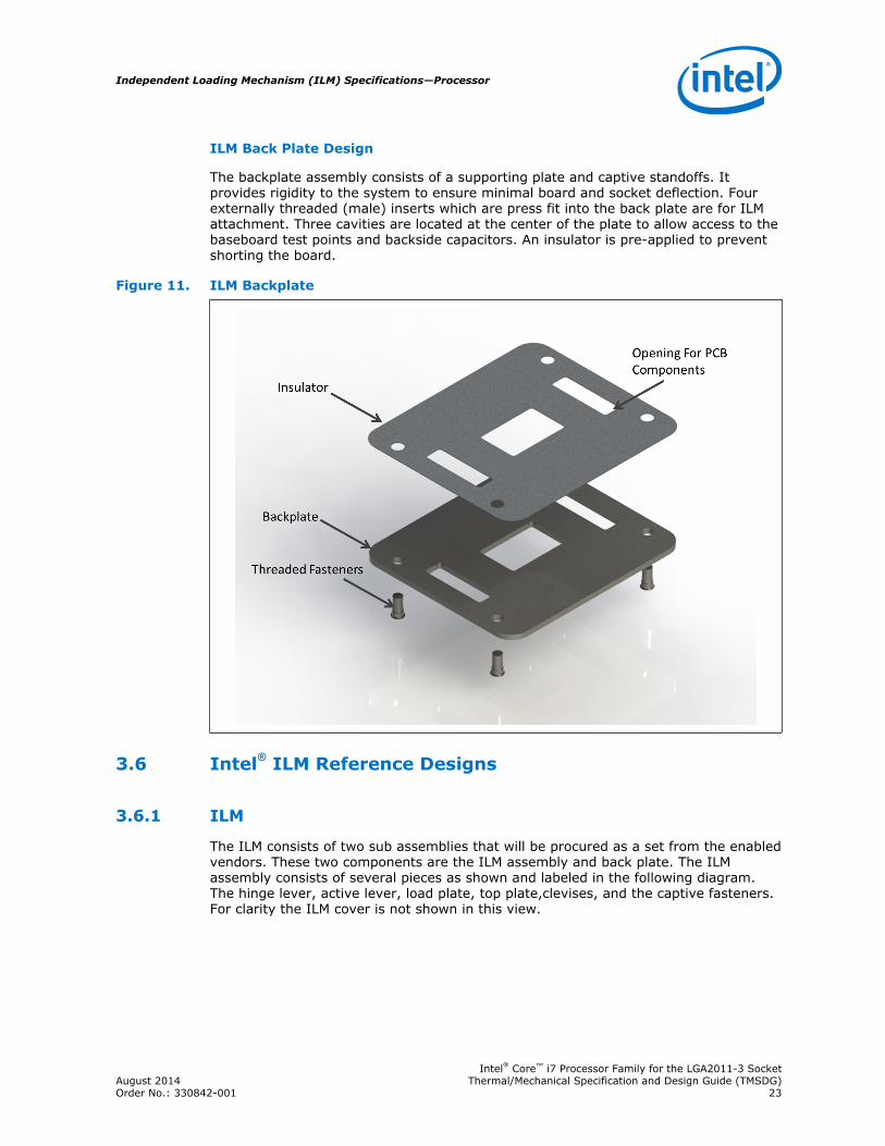
ILM Back Plate Design
The backplate assembly consists of a supporting plate and captive standoffs. Itprovides rigidity to the system to ensure minimal board and socket deflection. Fourexternally threaded (male) inserts which are press fit into the back plate are for ILMattachment. Three cavities are located at the center of the plate to allow access to thebaseboard test points and backside capacitors. An insulator is pre-applied to preventshorting the board.
Figure 11. ILM Backplate
Intel® ILM Reference Designs
ILM
The ILM consists of two sub assemblies that will be procured as a set from the enabledvendors. These two components are the ILM assembly and back plate. The ILMassembly consists of several pieces as shown and labeled in the following diagram.The hinge lever, active lever, load plate, top plate,clevises, and the captive fasteners.For clarity the ILM cover is not shown in this view.
3.6
3.6.1
Independent Loading Mechanism (ILM) Specifications—Processor
Intel® Core™ i7 Processor Family for the LGA2011-3 SocketAugust 2014 Thermal/Mechanical Specification and Design Guide (TMSDG)Order No.: 330842-001 23
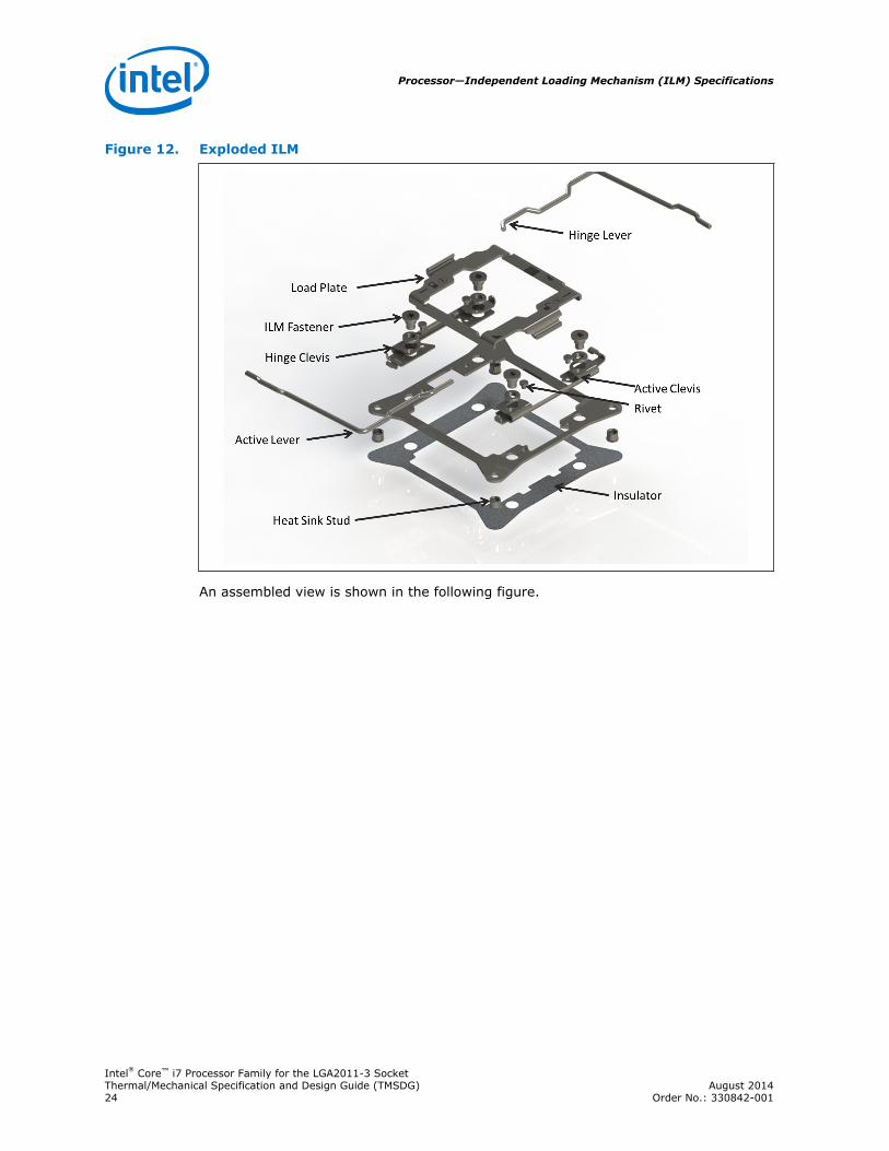
Figure 12. Exploded ILM
An assembled view is shown in the following figure.
Processor—Independent Loading Mechanism (ILM) Specifications
Intel® Core™ i7 Processor Family for the LGA2011-3 SocketThermal/Mechanical Specification and Design Guide (TMSDG) August 201424 Order No.: 330842-001
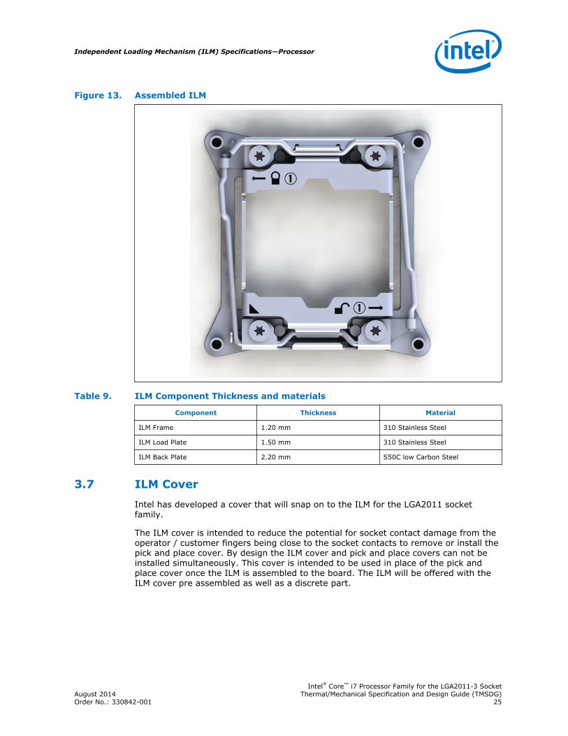
Figure 13. Assembled ILM
Table 9. ILM Component Thickness and materials
Component Thickness Material
ILM Frame 1.20 mm 310 Stainless Steel
ILM Load Plate 1.50 mm 310 Stainless Steel
ILM Back Plate 2.20 mm S50C low Carbon Steel
ILM Cover
Intel has developed a cover that will snap on to the ILM for the LGA2011 socketfamily.
The ILM cover is intended to reduce the potential for socket contact damage from theoperator / customer fingers being close to the socket contacts to remove or install thepick and place cover. By design the ILM cover and pick and place covers can not beinstalled simultaneously. This cover is intended to be used in place of the pick andplace cover once the ILM is assembled to the board. The ILM will be offered with theILM cover pre assembled as well as a discrete part.
3.7
Independent Loading Mechanism (ILM) Specifications—Processor
Intel® Core™ i7 Processor Family for the LGA2011-3 SocketAugust 2014 Thermal/Mechanical Specification and Design Guide (TMSDG)Order No.: 330842-001 25
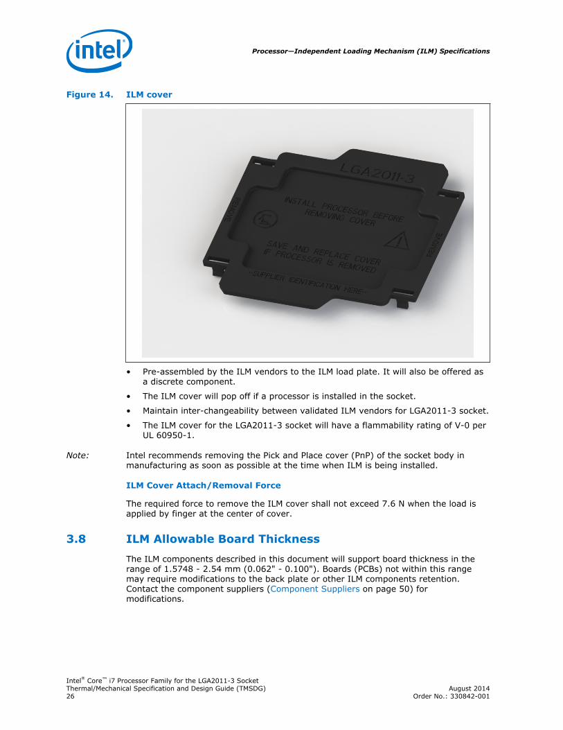
Figure 14. ILM cover
• Pre-assembled by the ILM vendors to the ILM load plate. It will also be offered asa discrete component.
• The ILM cover will pop off if a processor is installed in the socket.
• Maintain inter-changeability between validated ILM vendors for LGA2011-3 socket.
• The ILM cover for the LGA2011-3 socket will have a flammability rating of V-0 perUL 60950-1.
Note: Intel recommends removing the Pick and Place cover (PnP) of the socket body inmanufacturing as soon as possible at the time when ILM is being installed.
ILM Cover Attach/Removal Force
The required force to remove the ILM cover shall not exceed 7.6 N when the load isapplied by finger at the center of cover.
ILM Allowable Board Thickness
The ILM components described in this document will support board thickness in therange of 1.5748 - 2.54 mm (0.062" - 0.100"). Boards (PCBs) not within this rangemay require modifications to the back plate or other ILM components retention.Contact the component suppliers (Component Suppliers on page 50) formodifications.
3.8
Processor—Independent Loading Mechanism (ILM) Specifications
Intel® Core™ i7 Processor Family for the LGA2011-3 SocketThermal/Mechanical Specification and Design Guide (TMSDG) August 201426 Order No.: 330842-001
4.0 Processor Thermal Specifications and Features
Tcase and DTS-Based Thermal SpecificationImplementation
Thermal solutions should be sized such that the processor complies to the TCASEthermal profile all the way up to TDP, because, when all cores are active, a thermalsolution sized as such will have the capacity to meet the DTS thermal profile, bydesign. When all cores are not active or when Intel Turbo Boost Technology is active,attempting to comply with the DTS thermal profile may drive system fans to speedshigher than the fan speed required to comply with the TCASE thermal profile at TDP.
In cases where thermal solutions are undersized, and the processor does not complywith the TCASE thermal profile at TDP, compliance can occur when the processor poweris kept lower than TDP, AND the actual TCASE is below the TCASE thermal profile at thatlower power.
In most situations, implementation of DTS thermal profile can reduce average fanpower and improve acoustics, as compared to TCONTROL-based fan speed control.
Margin to Thermal Specification (M)
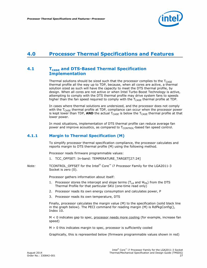
To simplify processor thermal specification compliance, the processor calculates andreports margin to DTS thermal profile (M) using the following method.
Processor reads firmware programmable values:
1. TCC_OFFSET: In-band: TEMPERATURE_TARGET[27:24]
Note: TCONTROL_OFFSET for the Intel® Core™ i7 Processor Family for the LGA2011-3Socket is zero (0).
Processor gathers information about itself:
1. Processor stores the intercept and slope terms (TLA and ΨPA) from the DTSThermal Profile for that particular SKU (one-time read only)
2. Processor reads its own energy consumption and calculates power, P
3. Processor reads its own temperature, DTS
Finally, processor calculates the margin value (M) to the specification (solid black linein the graph below). The PECI command for reading margin (M) is RdPkgConfig(),Index 10.
M < 0 indicates gap to spec, processor needs more cooling (for example, increase fanspeed)
M > 0 this indicates margin to spec, processor is sufficiently cooled
Graphically, this is represented below (firmware programmable values shown in red)
4.1
4.1.1
Processor Thermal Specifications and Features—Processor
Intel® Core™ i7 Processor Family for the LGA2011-3 SocketAugust 2014 Thermal/Mechanical Specification and Design Guide (TMSDG)Order No.: 330842-001 27

Figure 15. Margin to Thermal Spec (M)
DTS 2.0 processor margin values can be obtained via PECI or processor registers.Refer to the Processor Datasheet Volume 2 (see Reference Documents).
Table 10. DTS 2.0 Margin From PECI
Service IndexValue(IV)
(decimal)
ParameterValue
(word)
RdPkgConfig()Data
(dword)
WrPkgConfig()
Data(dword)
Description
Thermal Margin 10 0x0000 15:0--PackageTemperaturemargin in 8.8format, 32:16--Reserved
N/A Package temperaturemargin with regards toDTS Thermal Profile.Positive indicatesthermal margin, andpackage is less than DTSthermal profile
Processor—Processor Thermal Specifications and Features
Intel® Core™ i7 Processor Family for the LGA2011-3 SocketThermal/Mechanical Specification and Design Guide (TMSDG) August 201428 Order No.: 330842-001
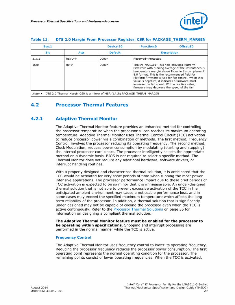
Table 11. DTS 2.0 Margin From Processor Register: CSR for PACKAGE_THERM_MARGIN
Bus:1 Device:30 Function:0 Offset:E0
Bit Attr Default Description
31:16 RSVD-P 0000h Reserved--Protected
15:0 R0-V 0000h THERM_MARGIN--This field provides PlatformFirmware with running average of the instantaneoustemperature margin above Tspec in 2's complement8.8 format. This is the recommended field forPlatform firmware to use for fan control. When thisvalue is negative, it indicates a firmware mustincrease the fan speed. With a positive value,firmware may decrease the speed of the fan
Note: • DTS 2.0 Thermal Margin CSR is a mirror of MSR (1A1h) PACKAGE_THERM_MARGIN
Processor Thermal Features
Adaptive Thermal Monitor
The Adaptive Thermal Monitor feature provides an enhanced method for controllingthe processor temperature when the processor silicon reaches its maximum operatingtemperature. Adaptive Thermal Monitor uses Thermal Control Circuit (TCC) activationto reduce processor power via a combination of methods. The first method, FrequencyControl, involves the processor reducing its operating frequency. The second method,Clock Modulation, reduces power consumption by modulating (starting and stopping)the internal processor core clocks. The processor intelligently selects the appropriatemethod on a dynamic basis. BIOS is not required to select a specific method. TheThermal Monitor does not require any additional hardware, software drivers, orinterrupt handling routines.
With a properly designed and characterized thermal solution, it is anticipated that theTCC would be activated for very short periods of time when running the most powerintensive applications. The processor performance impact due to these brief periods ofTCC activation is expected to be so minor that it is immeasurable. An under-designedthermal solution that is not able to prevent excessive activation of the TCC in theanticipated ambient environment may cause a noticeable performance loss, and insome cases may exceed the specified maximum temperature which affects the long-term reliability of the processor. In addition, a thermal solution that is significantlyunder-designed may not be capable of cooling the processor even when the TCC isactive continuously. Refer to the Processor Thermal Solutions on page 35 forinformation on designing a compliant thermal solution.
The Adaptive Thermal Monitor feature must be enabled for the processor tobe operating within specifications. Snooping and interrupt processing areperformed in the normal manner while the TCC is active.
Frequency Control
The Adaptive Thermal Monitor uses frequency control to lower its operating frequency.Reducing the processor frequency reduces the processor power consumption. The firstoperating point represents the normal operating condition for the processor. Theremaining points consist of lower operating frequencies. When the TCC is activated,
4.2
4.2.1
Processor Thermal Specifications and Features—Processor
Intel® Core™ i7 Processor Family for the LGA2011-3 SocketAugust 2014 Thermal/Mechanical Specification and Design Guide (TMSDG)Order No.: 330842-001 29

the processor automatically transitions to the new lower operating frequency. Thistransition occurs on the order of microseconds, µs. The processor continues to executeinstructions during this frequency transition.
Clock Modulation
Clock modulation is performed by alternately turning the clocks off and on at a dutycycle specific to the processor. The period of the duty cycle is configured to 32microseconds when the TCC is active. Cycle times are independent of processorfrequency. Clock modulation may also be initiated by software at a configurable dutycycle.
With either method, a small amount of hysteresis has been included to prevent rapidactive/inactive transitions of the TCC when the processor is near its maximumoperating temperature. Once it has dropped below the maximum operatingtemperature, and the hysteresis timer has expired, the TCC goes inactive.
On-Demand Mode
The processor provides an auxiliary mechanism that allows system software to forcethe processor to reduce its power consumption. This mechanism is referred to as "On-Demand" mode and is distinct from the Adaptive Thermal Monitor feature. On-Demand mode is intended as a means to reduce system power consumption. Systemsshould not rely on software usage of this mechanism to limit the processortemperature. If bit 4 of the IA32_CLOCK_MODULATION MSR is set to a '1', theprocessor will immediately reduce its power consumption via modulation (starting andstopping) of the internal core clock, independent of the processor temperature. Whenusing On-Demand mode, the duty cycle of the clock modulation is programmable viabits 3:0 of the same IA32_CLOCK_MODULATION MSR. In On-Demand mode, the dutycycle can be programmed from 6.25% on / 93.75% off to 93.75% on / 6.25% off in6.25% increments. On-Demand mode may be used in conjunction with the AdaptiveThermal Monitor; however, if the system tries to enable On-Demand mode at thesame time the TCC is engaged, the factory configured duty cycle of the TCC willoverride the duty cycle selected by the On-Demand mode.
PROCHOT_N Signal
For a detailed description of the PROCHOT_N Signal see Haswell-EN/EP/EP 4S/EXProcessor External Design Specification (EDS), Volume One: Architecture.
THERMTRIP_N Signal
Regardless whether Adaptive Thermal Monitor is enabled, in the event of acatastrophic cooling failure, the processor will automatically shut down when theprocessor has reached an elevated temperature. At this point, the THERMTRIP_Nsignal will go active and stay active. THERMTRIP_N activation is independent ofprocessor activity and does not generate any Intel® QuickPath Interconnecttransactions. If THERMTRIP_N is asserted, all processor power rails must be removedwithin a certain amount of time. Refer to the Processor Datasheet, Volume 1 (seeReference Documents) for timing specifications for removing power rails. Thetemperature at which THERMTRIP_N asserts is not user configurable and is notsoftware visible.
4.2.2
4.2.3
4.2.4
Processor—Processor Thermal Specifications and Features
Intel® Core™ i7 Processor Family for the LGA2011-3 SocketThermal/Mechanical Specification and Design Guide (TMSDG) August 201430 Order No.: 330842-001

Absolute Processor Temperature
The processor has a software readable field in the TEMPERATURE_TARGET registerthat contains the minimum temperature at which the Thermal Control Circuit (TCC)will be activated and PROCHOT_N will be asserted.
Intel does not test any third party software that reports absolute processortemperature. As such, Intel cannot recommend the use of software that claims thiscapability. Since there is part-to-part variation in the TCC (thermal control circuit)activation temperature, use of software that reports absolute temperature could bemisleading.
Processor Thermal Specifications
The processor requires a thermal solution to maintain temperatures within operatinglimits. Any attempt to operate the processor outside these limits may result inpermanent damage to the processor and potentially other components within thesystem. Maintaining the proper thermal environment is key to reliable, long-termsystem operation.
A complete solution includes both component and system level thermal managementfeatures. Component level thermal solutions can include active or passive heatsinksattached to the processor integrated heat spreader (IHS). Typical system levelthermal solutions may consist of system fans combined with ducting and venting.
For more information on designing a component level thermal solution, refer to Processor Thermal Solutions on page 35.
Thermal Specifications
To allow optimal operation and long-term reliability of Intel processor-based systems,the processor must remain between the minimum and maximum case temperature(TCASE) specifications as defined in the tables in the following sub-sections. Thermalsolutions that do not provide sufficient thermal cooling may affect the long-termreliability of the processor and system.
Thermal profiles ensure adherence to Intel reliability requirements.
Intel assumes specific system boundary conditions (system ambient, airflow, heatsinkperformance / pressure drop, preheat, etc.) for each processor SKU to develop Tcaseand DTS thermal specifications. For servers each processor will be aligned to wither1U or 2U system boundary conditions. Customers can use other boundary conditions(for example a better thermal solution with higher ambient) providing they arecompliant to those specifications. Furthermore, implementing a thermal solution thatviolates the thermal profile for extended periods of time may result in permanentdamage to the processor or reduced life. The upper point of the thermal profileconsists of the Thermal Design Power (TDP) and the corresponding TCASE_MAX value (x= TDP and y = TCASE_MAX) represents a thermal solution design point.
Intel recommends that thermal solution designs target the Thermal Design Power(TDP). The Adaptive Thermal Monitor feature is intended to help protect the processorin the event that an application exceeds the TDP recommendation for a sustained timeperiod. The Adaptive Thermal Monitor feature must be enabled for the processor toremain within its specifications.
4.2.5
4.3
4.3.1
Processor Thermal Specifications and Features—Processor
Intel® Core™ i7 Processor Family for the LGA2011-3 SocketAugust 2014 Thermal/Mechanical Specification and Design Guide (TMSDG)Order No.: 330842-001 31

TCASE and DTS Based Thermal Specifications
To simplify compliance to thermal specifications at processor run time, the processorhas a Digital Thermal Sensor (DTS) based thermal specification. Digital ThermalSensor outputs a relative die temperature from TCC activation temperature. TCASE-based specifications are used for heatsink sizing while DTS-based specs are used foracoustic and fan speed optimizations while the server is operating. Some SKUs mayshare the same TCASE thermal profiles but have distinct DTS thermal profiles.
All thermal profiles, whether based on TCASE or DTS, follow the straight-line equationformat namely, y = mx + b. Where,
y = temperature (T) in °C
m = slope (Ψ)
x = power (P) in Watts
b = y-intercept (TLA) (LA = local ambient)
Figure 16. Typical Thermal Profile Graph (Illustration Only)
4.3.2
Processor—Processor Thermal Specifications and Features
Intel® Core™ i7 Processor Family for the LGA2011-3 SocketThermal/Mechanical Specification and Design Guide (TMSDG) August 201432 Order No.: 330842-001

Processor Thermal Specifications
ProcessorNumber
TDP (W) 2 Core Count TCONTROL Thermal Profiles 6 Notes
TCASE5 DTS
i7-5960X 140 8 18 TC=[0.170*P] + 43.3
TDTS=[0.398*P] + 43.3
1, 3, 4
i7-5930K 140 6 10 TC=[0.170*P] + 43.2
TDTS=[0.396*P] + 43.2
1, 3, 4
i7-5820K 140 6 10 TC=[0.170*P] + 43.2
TDTS=[0.396*P] + 43.2
1, 3, 4
Notes: 1. These values are specified at VccIN_MAX for all processor frequencies. Systems must bedesigned to ensure the processor is not subjected to any static Vcc and Icc combination whereinVccIN exceed VccIN_MAX at a specified Icc. Refer to the electrical loadline specifications.
2. Thermal Design Power (TDP) should be used as a target for processor thermal solution design atmaximum TCASE. Processor power may exceed TDP for short durations. See Intel Turbo BoostTechnology.
3. These specifications are based on initial pre-silicon simulations and are subject to change asfurther characterization data becomes available.
4. Power specifications are defined at all VIDs found in the Processor Datasheet, Volume 1 (seeReference Documents).
5. The TCASE Thermal Profile is based on the LGA2011-0 Thermal Test Vehicle (TTV).6. ѰPA specifications are based on the DRA-A and T-HPHS thermal solutions. Therefore, there is no
change to the requirements from the 2nd and 3rd Generation Intel® Core™ i7 processors for theLGA2011 socket.
Thermal Metrology
The minimum and maximum case temperatures (TCASE) specified are measured at thegeometric top center of the processor integrated heat spreader (IHS). The followingfigures illustrate the location where TCASE temperature measurements should bemade. The figures also include geometry guidance for modifying the IHS to accept athermocouple probe.
4.3.3
4.3.4
Processor Thermal Specifications and Features—Processor
Intel® Core™ i7 Processor Family for the LGA2011-3 SocketAugust 2014 Thermal/Mechanical Specification and Design Guide (TMSDG)Order No.: 330842-001 33

Figure 17. Case Temperature (TCASE) Measurement Location
25.2
30
22.500
A
B
BPIN 1 INDICATOR
1.020 ±0.250
0.790 ±0.1500.380 ±0.030
PACKAGE CENTER
DETAIL A
0.381 ±0.0380.510 ±0.080 SECTION B
Grantley Small PackageUnits are mm
Note: Figure is not to scale and is for reference only.
Processor—Processor Thermal Specifications and Features
Intel® Core™ i7 Processor Family for the LGA2011-3 SocketThermal/Mechanical Specification and Design Guide (TMSDG) August 201434 Order No.: 330842-001
5.0 Processor Thermal Solutions
Heatsink Design Considerations
To remove the heat from the processor, three basic parameters should be considered:
• The area of the surface on which the heat transfer takes place - Without anyenhancements, this is the surface of the processor package IHS. One method usedto improve thermal performance is to attach a heatsink to the IHS. A heatsink canincrease the effective heat transfer surface area by conducting heat out of the IHSand into the surrounding air through fins attached to the heatsink base.
• The conduction path from the heat source to the heatsink fins - Providing a directconduction path from the heat source to the heatsink fins and selecting materialswith higher thermal conductivity typically improves heatsink performance. Thelength, thickness, and conductivity of the conduction path from the heat source tothe fins directly impact the thermal performance of the heatsink. In particular, thequality of the contact between the package IHS and the heatsink base has ahigher impact on the overall thermal solution performance as processor coolingrequirements become strict. Thermal interface material (TIM) is used to fill in thegap between the IHS and the bottom surface of the heatsink, and therebyimproves the overall performance of the thermal stackup (IHS-TIM-Heatsink).With extremely poor heatsink interface flatness or roughness, TIM may notadequately fill the gap. The TIM thermal performance depends on its thermalconductivity as well as the pressure load applied to it.
• The heat transfer conditions on the surface upon which heat transfer takes place -Convective heat transfer occurs between the airflow and the surface exposed tothe flow. It is characterized by the local ambient temperature of the air, TLA, andthe local air velocity over the surface. The higher the air velocity over the surface,the more efficient the resulting cooling. The nature of the airflow can also enhanceheat transfer via convection. Turbulent flow can provide improvement overlaminar flow. In the case of a heatsink, the surface exposed to the flow includesthe fin faces and the heatsink base.
An active heatsink typically incorporates a fan that helps manage the airflow throughthe heatsink.
Passive heatsink solutions require in-depth knowledge of the airflow in the chassis.Typically, passive heatsinks see slower air speed. Therefore, these heatsinks aretypically larger (and heavier) than active heatsinks due to the increase in fin surfacenecessary to meet a required performance. As the heatsink fin density (the number offins in a given cross-section) increases, the resistance to the airflow increases; it ismore likely that the air will travel around the heatsink instead of through it, unless airbypass is carefully managed. Using air-ducting techniques to manage bypass area isan effective method for maximizing airflow through the heatsink fins.
5.1
Processor Thermal Solutions—Processor
Intel® Core™ i7 Processor Family for the LGA2011-3 SocketAugust 2014 Thermal/Mechanical Specification and Design Guide (TMSDG)Order No.: 330842-001 35

Thermal Design Guidelines
Intel® Turbo Boost Technology
Intel® Turbo Boost Technology is a feature available on certain Intel® Core™ i7Processor Family for the LGA2011-3 Socket SKUs that opportunistically, andautomatically allows the processor to run faster than the marked frequency if the partis operating below certain power and temperature limits. With Turbo Boost enabled,the instantaneous processor power can exceed TDP for short durations resulting inincreased performance.
System thermal design should consider the following important parameters (set viaBIOS):
• POWER_LIMIT_1 (PL1) = average processor power over a long time window(default setting is TDP)
• POWER_LIMIT_2 (PL2) = average processor power over a short time windowabove TDP (short excursions). Maximum allowed by the processor is 20% aboveTDP for all SKUs (1.2 * TDP). Note that actual power will include IMON inaccuracy.
• POWER_LIMIT_1_TIME (Tau) = time constant for the exponential weightedmoving average (EWMA) which optimizes performance while reducing thermalrisk. (dictates how quickly power decays from its peak)
Please note that although the processor can exceed PL1 (default TDP) for a certainamount of time, the exponential weighted moving average (EWMA) power will neverexceed PL1.
A properly designed processor thermal solution is important to maximizing TurboBoost performance. However, heatsink performance (thermal resistance, Ψ CA) is onlyone of several factors that can impact the amount of benefit. Other factors areoperating environment, workload and system design. With Turbo Mode enabled, theprocessor may run more consistently at higher power levels, and be more likely tooperate above TCONTROL, as compared to when Turbo Mode is disabled. This may resultin higher acoustics.
Thermal Excursion Power
Under fan failure or other anomalous thermal excursions, processor temperature(either TCASE or DTS) may exceed the thermal profile for a duration totaling less than360 hours per year without affecting long term reliability (life) of the processor. Formore typical thermal excursions, Thermal Monitor is expected to control the processorpower level as long as conditions do not allow the processor to exceed thetemperature at which Thermal Control Circuit (TCC) activation initially occurred.
Under more severe anomalous thermal excursions when the processor temperaturecannot be controlled at or below thermal profile by TCC activation, then data integrityis not assured. At some higher thresholds, THERMTRIP_N will enable a shut down inan attempt to prevent permanent damage to the processor.
Thermal Characterization Parameters
The case-to-local ambient Thermal Characterization Parameter ( Ψ CA ) is defined by:
Ψ CA = (Tcase - TLA) / TDP
5.2
5.2.1
5.2.2
5.2.3
Processor—Processor Thermal Solutions
Intel® Core™ i7 Processor Family for the LGA2011-3 SocketThermal/Mechanical Specification and Design Guide (TMSDG) August 201436 Order No.: 330842-001

Where:
T CASE = Processor case temperature (°C)
T LA = Local ambient temperature before the air enters the processor heatsink (°C)
TDP = TDP (W) assumes all power dissipates through the integrated heat spreader.This inexact assumption is convenient for heatsink design.
Ψ CA = Ψ CS + Ψ SA
Where:
Ψ CS = Thermal characterization parameter of the TIM (°C/W) is dependent on thethermal conductivity and thickness of the TIM.
Ψ SA = Thermal characterization parameter from heatsink-to-local ambient (°C/W) isdependent on the thermal conductivity and geometry of the heatsink and dependenton the air velocity through the heatsink fins.
The following figure illustrates the thermal characterization parameters.
Figure 18. Thermal Characterization Parameters
Processor Thermal Solutions—Processor
Intel® Core™ i7 Processor Family for the LGA2011-3 SocketAugust 2014 Thermal/Mechanical Specification and Design Guide (TMSDG)Order No.: 330842-001 37
Thermal Interface Material (TIM) Considerations
Thermal Interface Material between the processor IHS and the heatsink base isnecessary to improve thermal conduction from the IHS to the heatsink. Many thermalinterface materials can be pre-applied to the heatsink base prior to shipment from theheatsink supplier without the need for a separate TIM dispense or attachment processin the final assembly factory.
All thermal interface materials should be sized and positioned on the heatsink base ina way that ensures that the entire area is covered. It is important to compensate forheatsink-to-processor positional alignment when selecting the proper TIM size.
When pre-applied material is used, it is recommended to have a protective cover.Protective tape is not recommended as the TIM could be damaged during its removalstep.
Thermal performance usually degrades over the life of the assembly and thisdegradation needs to be accounted for in the thermal performance. Degradation canbe caused by shipping and handling, environmental temperature, humidity conditions,load relaxation over time, temperature cycling or material changes (most notably inthe TIM) over time. For this reason, the measured TCASE value of a given processormay increase over time, depending on the type of TIM material.
Mechanical Recommendations and Targets
Thermal solutions should be designed to meet the mechanical requirements describedin this section.
Keep in mind that the heatsink retention will need to apply additional load in order toachieve the minimum Socket Static Total Compressive load. This load should bedistributed over the IHS (Integrated Heat Spreader). The dual-loading approach isrepresented by the following equation.
FILM + FHEATSINK = FSOCKET
Processor / Socket Stackup Height
The following table provides the stackup height of a processor and LGA2011-3 socketwith processor fully seated. This value is the root sum of squares summation of: (a)the height of the socket seating plane above the motherboard after reflow, (b) theheight of the package, from the package seating plane to the top of the IHS, andaccounting for its nominal variation and tolerances given in the processor, socket andILM drawings
5.3
5.4
5.4.1
Processor—Processor Thermal Solutions
Intel® Core™ i7 Processor Family for the LGA2011-3 SocketThermal/Mechanical Specification and Design Guide (TMSDG) August 201438 Order No.: 330842-001
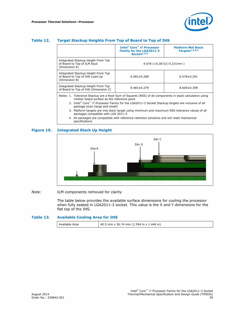
Table 12. Target Stackup Heights From Top of Board to Top of IHS
Intel® Core™ i7 ProcessorFamily for the LGA2011-3
Socket1,2,4
Platform Mid StackTargets1,2,3,4
Integrated Stackup Height From Topof Board to Top of ILM Stud(Dimension A)
4.678 (+0.367)/(-0.231mm )
Integrated Stackup Height From Topof Board to Top of IHS Load Lip(Dimension B)
6.581±0.289 6.578±0.291
Integrated Stackup Height From Topof Board to Top of IHS (Dimension C) 8.481±0.279 8.600±0.399
Notes: 1. Tolerance Stackus are a Root Sum of Squares (RSS) of all components in stack calculation usingmother board surface as the reference point
2. Intel® Core™ i7 Processor Family for the LGA2011-3 Socket Stackup targets are inclusive of allpackage sizes (large and small)
3. Platform targets are mid stack target using minimum and maximum RSS tolerance values of allpackages compatible with LGA 2011-3
4. All packages are compatible with reference retention solutions and will meet mechanicalspecifications
Figure 19. Integrated Stack Up Height
Note: ILM components removed for clarity
The table below provides the available surface dimensions for cooling the processorwhen fully seated in LGA2011-3 socket. This value is the X and Y dimensions for theflat top of the IHS.
Table 13. Available Cooling Area for IHS
Available Area 40.5 mm x 36.74 mm (1.594 in x 1.446 in)
Processor Thermal Solutions—Processor
Intel® Core™ i7 Processor Family for the LGA2011-3 SocketAugust 2014 Thermal/Mechanical Specification and Design Guide (TMSDG)Order No.: 330842-001 39
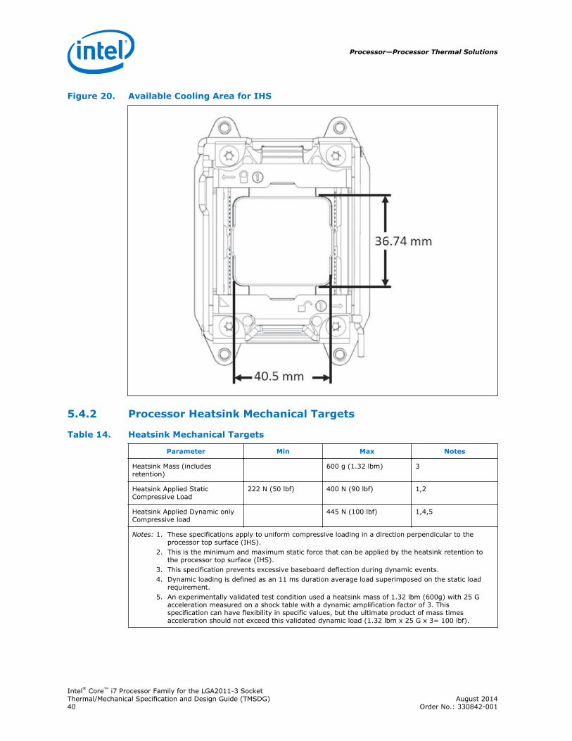
Figure 20. Available Cooling Area for IHS
Processor Heatsink Mechanical Targets
Table 14. Heatsink Mechanical Targets
Parameter Min Max Notes
Heatsink Mass (includesretention)
600 g (1.32 lbm) 3
Heatsink Applied StaticCompressive Load
222 N (50 lbf) 400 N (90 lbf) 1,2
Heatsink Applied Dynamic onlyCompressive load
445 N (100 lbf) 1,4,5
Notes: 1. These specifications apply to uniform compressive loading in a direction perpendicular to theprocessor top surface (IHS).
2. This is the minimum and maximum static force that can be applied by the heatsink retention tothe processor top surface (IHS).
3. This specification prevents excessive baseboard deflection during dynamic events.4. Dynamic loading is defined as an 11 ms duration average load superimposed on the static load
requirement.5. An experimentally validated test condition used a heatsink mass of 1.32 lbm (600g) with 25 G
acceleration measured on a shock table with a dynamic amplification factor of 3. Thisspecification can have flexibility in specific values, but the ultimate product of mass timesacceleration should not exceed this validated dynamic load (1.32 lbm x 25 G x 3= 100 lbf).
5.4.2
Processor—Processor Thermal Solutions
Intel® Core™ i7 Processor Family for the LGA2011-3 SocketThermal/Mechanical Specification and Design Guide (TMSDG) August 201440 Order No.: 330842-001
Heatsink Mechanical and Structural Considerations
An attachment mechanism must be designed to support the heatsink because thereare no features on the socket on which to directly attach a heatsink. In addition toholding the heatsink in place on top of the IHS, this mechanism plays a significant rolein the performance of the system, in particular:
• Ensuring thermal performance of the TIM applied between the IHS and theheatsink. TIMs, especially those based on phase change materials, are verysensitive to applied pressure: the higher the pressure, the better the initialperformance. TIMs such as thermal greases are not as sensitive to appliedpressure. Designs should consider the possible decrease in applied pressure overtime due to potential structural relaxation in enabled components.
• Ensuring system electrical, thermal, and structural integrity under shock andvibration events, particularly the socket solder joints. The mechanicalrequirements of the attachment mechanism depend on the weight of the heatsinkand the level of shock and vibration that the system must support. The overallstructural design of the baseboard and system must be considered when designingthe heatsink attachment mechanism. Their design should provide a means forprotecting socket solder joints, as well as preventing package pullout from thesocket.
Please note that the load applied by the attachment mechanism must comply with theprocessor mechanical specifications, along with the dynamic load added by themechanical shock and vibration requirements, as discussed in Package LoadingSpecifications on page 42.
A potential mechanical solution for heavy heatsinks is the use of a supportingmechanism such as a backer plate or the utilization of a direct attachment of theheatsink to the chassis pan. In these cases, the strength of the supporting componentcan be utilized rather than solely relying on the baseboard strength. In addition to thegeneral guidelines given above, contact with the baseboard surfaces should beminimized during installation in order to avoid any damage to the baseboard.
5.5
Processor Thermal Solutions—Processor
Intel® Core™ i7 Processor Family for the LGA2011-3 SocketAugust 2014 Thermal/Mechanical Specification and Design Guide (TMSDG)Order No.: 330842-001 41
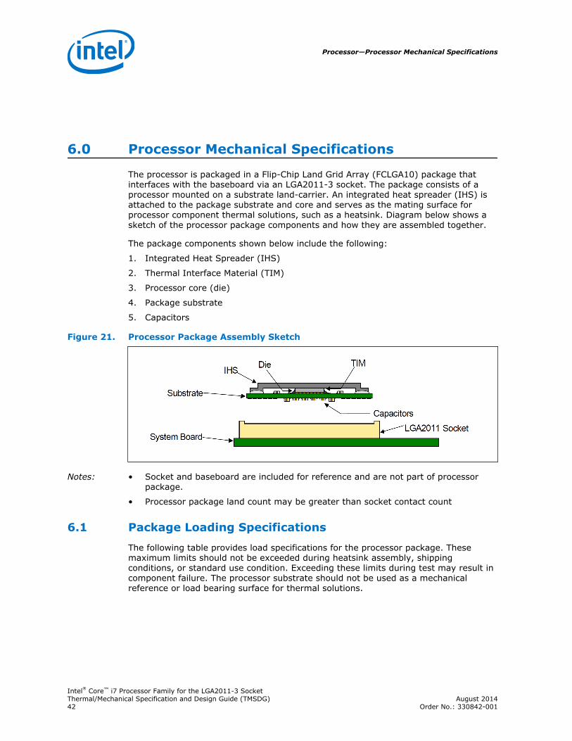
6.0 Processor Mechanical Specifications
The processor is packaged in a Flip-Chip Land Grid Array (FCLGA10) package thatinterfaces with the baseboard via an LGA2011-3 socket. The package consists of aprocessor mounted on a substrate land-carrier. An integrated heat spreader (IHS) isattached to the package substrate and core and serves as the mating surface forprocessor component thermal solutions, such as a heatsink. Diagram below shows asketch of the processor package components and how they are assembled together.
The package components shown below include the following:
1. Integrated Heat Spreader (IHS)
2. Thermal Interface Material (TIM)
3. Processor core (die)
4. Package substrate
5. Capacitors
Figure 21. Processor Package Assembly Sketch
Notes: • Socket and baseboard are included for reference and are not part of processorpackage.
• Processor package land count may be greater than socket contact count
Package Loading Specifications
The following table provides load specifications for the processor package. Thesemaximum limits should not be exceeded during heatsink assembly, shippingconditions, or standard use condition. Exceeding these limits during test may result incomponent failure. The processor substrate should not be used as a mechanicalreference or load bearing surface for thermal solutions.
6.1
Processor—Processor Mechanical Specifications
Intel® Core™ i7 Processor Family for the LGA2011-3 SocketThermal/Mechanical Specification and Design Guide (TMSDG) August 201442 Order No.: 330842-001
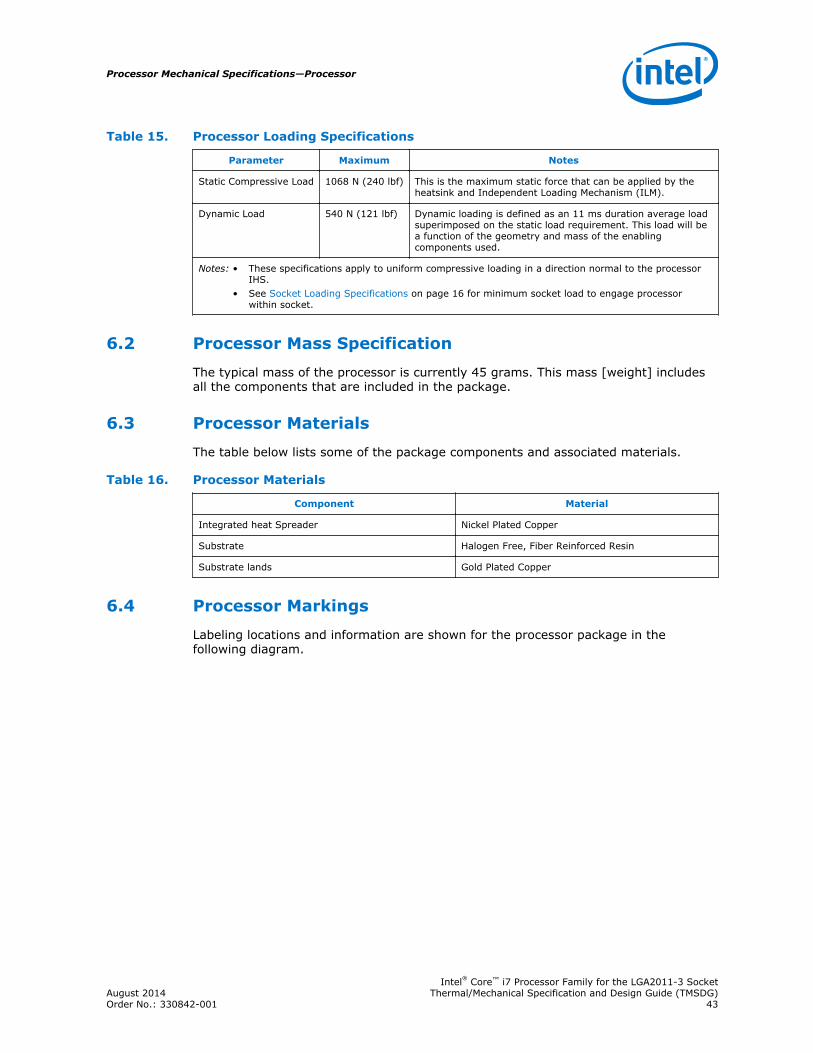
Table 15. Processor Loading Specifications
Parameter Maximum Notes
Static Compressive Load 1068 N (240 lbf) This is the maximum static force that can be applied by theheatsink and Independent Loading Mechanism (ILM).
Dynamic Load 540 N (121 lbf) Dynamic loading is defined as an 11 ms duration average loadsuperimposed on the static load requirement. This load will bea function of the geometry and mass of the enablingcomponents used.
Notes: • These specifications apply to uniform compressive loading in a direction normal to the processorIHS.
• See Socket Loading Specifications on page 16 for minimum socket load to engage processorwithin socket.
Processor Mass Specification
The typical mass of the processor is currently 45 grams. This mass [weight] includesall the components that are included in the package.
Processor Materials
The table below lists some of the package components and associated materials.
Table 16. Processor Materials
Component Material
Integrated heat Spreader Nickel Plated Copper
Substrate Halogen Free, Fiber Reinforced Resin
Substrate lands Gold Plated Copper
Processor Markings
Labeling locations and information are shown for the processor package in thefollowing diagram.
6.2
6.3
6.4
Processor Mechanical Specifications—Processor
Intel® Core™ i7 Processor Family for the LGA2011-3 SocketAugust 2014 Thermal/Mechanical Specification and Design Guide (TMSDG)Order No.: 330842-001 43
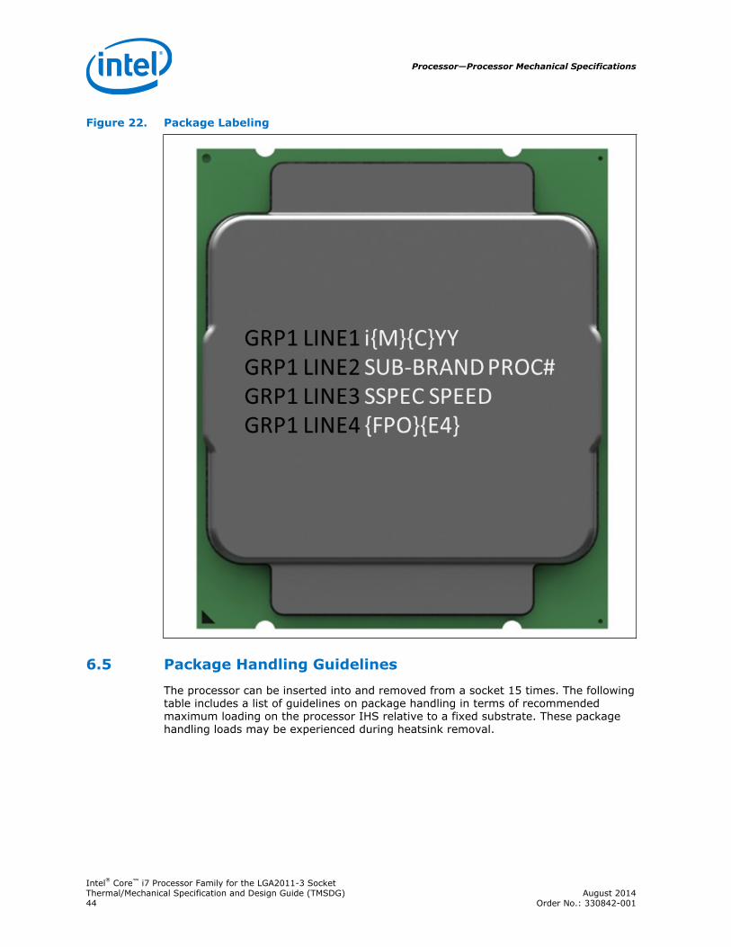
Figure 22. Package Labeling
Package Handling Guidelines
The processor can be inserted into and removed from a socket 15 times. The followingtable includes a list of guidelines on package handling in terms of recommendedmaximum loading on the processor IHS relative to a fixed substrate. These packagehandling loads may be experienced during heatsink removal.
6.5
Processor—Processor Mechanical Specifications
Intel® Core™ i7 Processor Family for the LGA2011-3 SocketThermal/Mechanical Specification and Design Guide (TMSDG) August 201444 Order No.: 330842-001
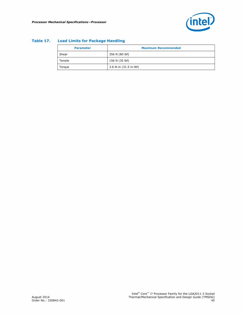
Table 17. Load Limits for Package Handling
Parameter Maximum Recommended
Shear 356 N (80 lbf)
Tensile 156 N (35 lbf)
Torque 3.6 N-m (31.5 in-lbf)
Processor Mechanical Specifications—Processor
Intel® Core™ i7 Processor Family for the LGA2011-3 SocketAugust 2014 Thermal/Mechanical Specification and Design Guide (TMSDG)Order No.: 330842-001 45
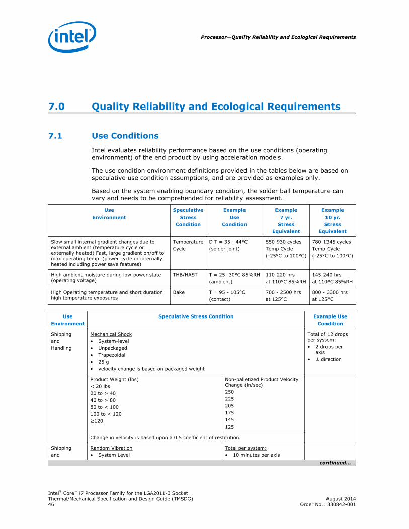
7.0 Quality Reliability and Ecological Requirements
Use Conditions
Intel evaluates reliability performance based on the use conditions (operatingenvironment) of the end product by using acceleration models.
The use condition environment definitions provided in the tables below are based onspeculative use condition assumptions, and are provided as examples only.
Based on the system enabling boundary condition, the solder ball temperature canvary and needs to be comprehended for reliability assessment.
UseEnvironment
SpeculativeStress
Condition
ExampleUse
Condition
Example7 yr.
StressEquivalent
Example10 yr.Stress
Equivalent
Slow small internal gradient changes due toexternal ambient (temperature cycle orexternally heated) Fast, large gradient on/off tomax operating temp. (power cycle or internallyheated including power save features)
TemperatureCycle
D T = 35 - 44°C(solder joint)
550-930 cyclesTemp Cycle(-25°C to 100°C)
780-1345 cyclesTemp Cycle(-25°C to 100°C)
High ambient moisture during low-power state(operating voltage)
THB/HAST T = 25 -30°C 85%RH(ambient)
110-220 hrsat 110°C 85%RH
145-240 hrsat 110°C 85%RH
High Operating temperature and short durationhigh temperature exposures
Bake T = 95 - 105°C(contact)
700 - 2500 hrsat 125°C
800 - 3300 hrsat 125°C
UseEnvironment
Speculative Stress Condition Example UseCondition
ShippingandHandling
Mechanical Shock• System-level• Unpackaged• Trapezoidal• 25 g• velocity change is based on packaged weight
Total of 12 dropsper system:• 2 drops per
axis• ± direction
Product Weight (lbs)< 20 lbs20 to > 4040 to > 8080 to < 100100 to < 120≥120
Non-palletized Product VelocityChange (in/sec)250225205175145125
Change in velocity is based upon a 0.5 coefficient of restitution.
Shippingand
Random Vibration• System Level
Total per system:• 10 minutes per axis
continued...
7.1
Processor—Quality Reliability and Ecological Requirements
Intel® Core™ i7 Processor Family for the LGA2011-3 SocketThermal/Mechanical Specification and Design Guide (TMSDG) August 201446 Order No.: 330842-001
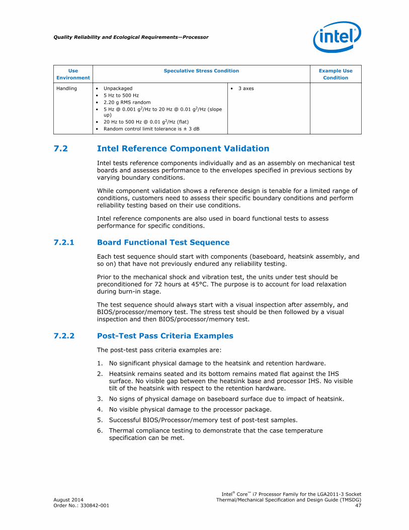
UseEnvironment
Speculative Stress Condition Example UseCondition
Handling • Unpackaged• 5 Hz to 500 Hz• 2.20 g RMS random• 5 Hz @ 0.001 g2/Hz to 20 Hz @ 0.01 g2/Hz (slope
up)• 20 Hz to 500 Hz @ 0.01 g2/Hz (flat)• Random control limit tolerance is ± 3 dB
• 3 axes
Intel Reference Component Validation
Intel tests reference components individually and as an assembly on mechanical testboards and assesses performance to the envelopes specified in previous sections byvarying boundary conditions.
While component validation shows a reference design is tenable for a limited range ofconditions, customers need to assess their specific boundary conditions and performreliability testing based on their use conditions.
Intel reference components are also used in board functional tests to assessperformance for specific conditions.
Board Functional Test Sequence
Each test sequence should start with components (baseboard, heatsink assembly, andso on) that have not previously endured any reliability testing.
Prior to the mechanical shock and vibration test, the units under test should bepreconditioned for 72 hours at 45°C. The purpose is to account for load relaxationduring burn-in stage.
The test sequence should always start with a visual inspection after assembly, andBIOS/processor/memory test. The stress test should be then followed by a visualinspection and then BIOS/processor/memory test.
Post-Test Pass Criteria Examples
The post-test pass criteria examples are:
1. No significant physical damage to the heatsink and retention hardware.
2. Heatsink remains seated and its bottom remains mated flat against the IHSsurface. No visible gap between the heatsink base and processor IHS. No visibletilt of the heatsink with respect to the retention hardware.
3. No signs of physical damage on baseboard surface due to impact of heatsink.
4. No visible physical damage to the processor package.
5. Successful BIOS/Processor/memory test of post-test samples.
6. Thermal compliance testing to demonstrate that the case temperaturespecification can be met.
7.2
7.2.1
7.2.2
Quality Reliability and Ecological Requirements—Processor
Intel® Core™ i7 Processor Family for the LGA2011-3 SocketAugust 2014 Thermal/Mechanical Specification and Design Guide (TMSDG)Order No.: 330842-001 47

Recommended BIOS/Processor/Memory Test Procedures
This test is to ensure proper operation of the product before and after environmentalstresses, with the thermal mechanical enabling components assembled. The test shallbe conducted on a fully operational baseboard that has not been exposed to anybattery of tests prior to the test being considered.
Testing setup should include the following components, properly assembled and/orconnected:
• Appropriate system baseboard.
• Processor and memory.
• All enabling components, including socket and thermal solution parts.
The pass criterion is that the system under test shall successfully complete thechecking of BIOS, basic processor functions and memory, without any errors. Intel PCDiags is an example of software that can be utilized for this test.
Material and Recycling Requirements
Material shall be resistant to fungal growth. Examples of non-resistant materialsinclude cellulose materials, animal and vegetable based adhesives, grease, oils, andmany hydrocarbons. Synthetic materials such as PVC formulations, certainpolyurethane compositions (for example, polyester and some polyethers), plasticswhich contain organic fillers of laminating materials, paints, and varnishes also aresusceptible to fungal growth. If materials are not fungal growth resistant, then MIL-STD-810E, Method 508.4 must be performed to determine material performance.Cadmium shall not be used in the painting or plating of the socket. CFCs and HFCsshall not be used in manufacturing the socket.
Any plastic component exceeding 25 gm should be recyclable per the European BlueAngel recycling standards.
Supplier is responsible for complying with industry standards regarding environmentalcare as well as with the specific standards required per supplier's region. Morespecifically, supplier is responsible for compliance with the European regulationsrelated to restrictions on the use of Lead and Bromine containing flame-retardants.Legislation varies by geography, European Union (RoHS/WEEE), China, California, andso forth.
The following definitions apply to the use of the terms lead-free, Pb-free, and RoHScompliant.
Halogen flame retardant free (HFR-Free) PCB: Current guidance for the socketpad layout supports FR4 and HFR-Free designs. In future revisions of this document,Intel will be providing guidance on the mechanical impact to using a HFR-free laminatein the PCB. This will be limited to workstations.
Lead-free and Pb-free: Lead has not been intentionally added, but lead may stillexist as an impurity below 1000 ppm.
RoHS compliant: Lead and other materials banned in RoHS Directive are either (1)below all applicable substance thresholds as proposed by the EU or (2) an approved/pending exemption applies.
7.2.3
7.3
Processor—Quality Reliability and Ecological Requirements
Intel® Core™ i7 Processor Family for the LGA2011-3 SocketThermal/Mechanical Specification and Design Guide (TMSDG) August 201448 Order No.: 330842-001
Note: RoHS implementation details are not fully defined and may change.
Quality Reliability and Ecological Requirements—Processor
Intel® Core™ i7 Processor Family for the LGA2011-3 SocketAugust 2014 Thermal/Mechanical Specification and Design Guide (TMSDG)Order No.: 330842-001 49
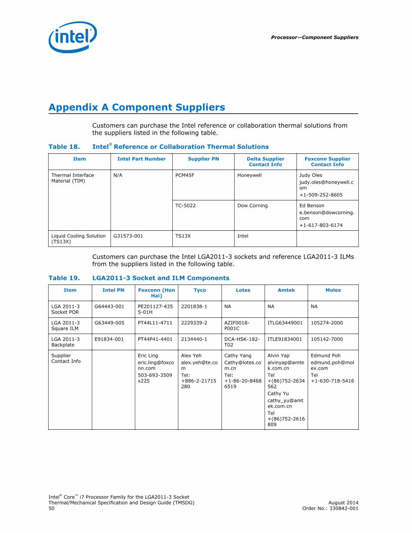
Appendix A Component Suppliers
Customers can purchase the Intel reference or collaboration thermal solutions fromthe suppliers listed in the following table.
Table 18. Intel® Reference or Collaboration Thermal Solutions
Item Intel Part Number Supplier PN Delta SupplierContact Info
Foxconn SupplierContact Info
Thermal InterfaceMaterial (TIM)
N/A PCM45F Honeywell Judy [email protected]+1-509-252-8605
TC-5022 Dow Corning Ed [email protected]+1-617-803-6174
Liquid Cooling Solution(TS13X)
G31573-001 TS13X Intel
Customers can purchase the Intel LGA2011-3 sockets and reference LGA2011-3 ILMsfrom the suppliers listed in the following table.
Table 19. LGA2011-3 Socket and ILM Components
Item Intel PN Foxconn (HonHai)
Tyco Lotes Amtek Molex
LGA 2011-3Socket POR
G64443-001 PE201127-4355-01H
2201838-1 NA NA NA
LGA 2011-3Square ILM
G63449-005 PT44L11-4711 2229339-2 AZIF0018-P001C
ITLG63449001 105274-2000
LGA 2011-3Backplate
E91834-001 PT44P41-4401 2134440-1 DCA-HSK-182-T02
ITLE91834001 105142-7000
SupplierContact Info
Eric [email protected]
Alex [email protected]:+886-2-21715280
Cathy [email protected]:+1-86-20-84686519
Alvin [email protected]+(86)752-2634562Cathy [email protected]+(86)752-2616809
Edmund [email protected]+1-630-718-5416
Processor—Component Suppliers
Intel® Core™ i7 Processor Family for the LGA2011-3 SocketThermal/Mechanical Specification and Design Guide (TMSDG) August 201450 Order No.: 330842-001
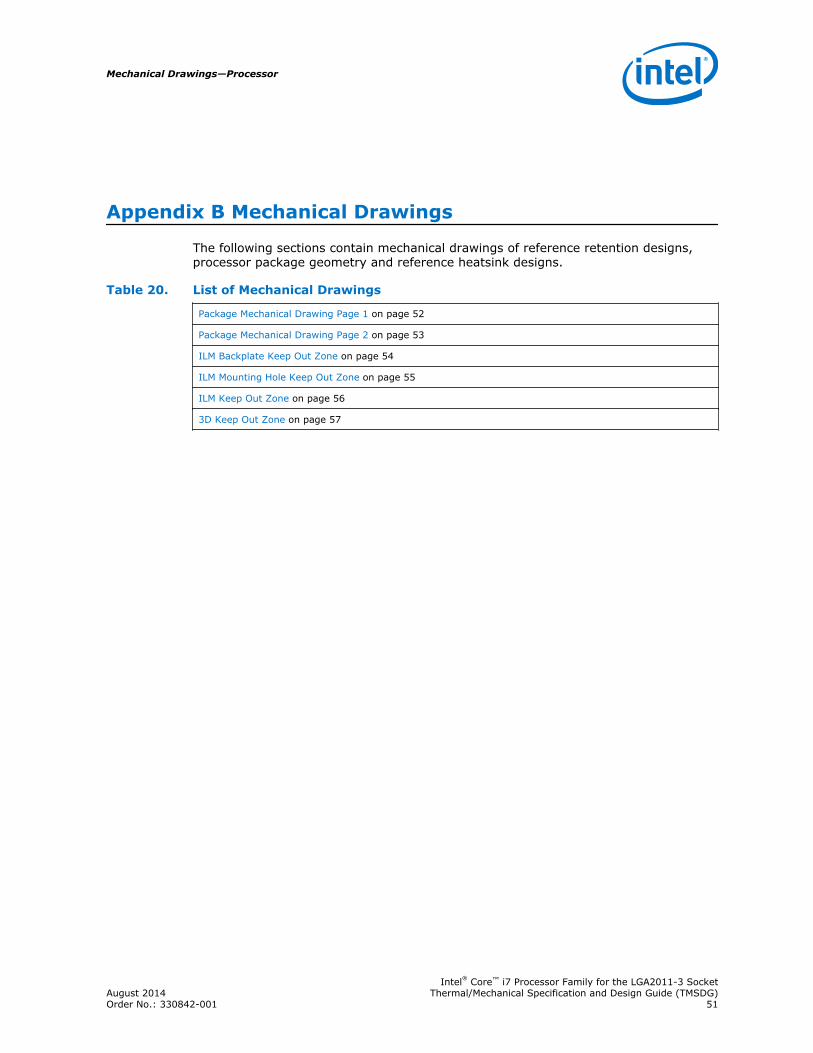
Appendix B Mechanical Drawings
The following sections contain mechanical drawings of reference retention designs,processor package geometry and reference heatsink designs.
Table 20. List of Mechanical Drawings
Package Mechanical Drawing Page 1 on page 52
Package Mechanical Drawing Page 2 on page 53
ILM Backplate Keep Out Zone on page 54
ILM Mounting Hole Keep Out Zone on page 55
ILM Keep Out Zone on page 56
3D Keep Out Zone on page 57
Mechanical Drawings—Processor
Intel® Core™ i7 Processor Family for the LGA2011-3 SocketAugust 2014 Thermal/Mechanical Specification and Design Guide (TMSDG)Order No.: 330842-001 51
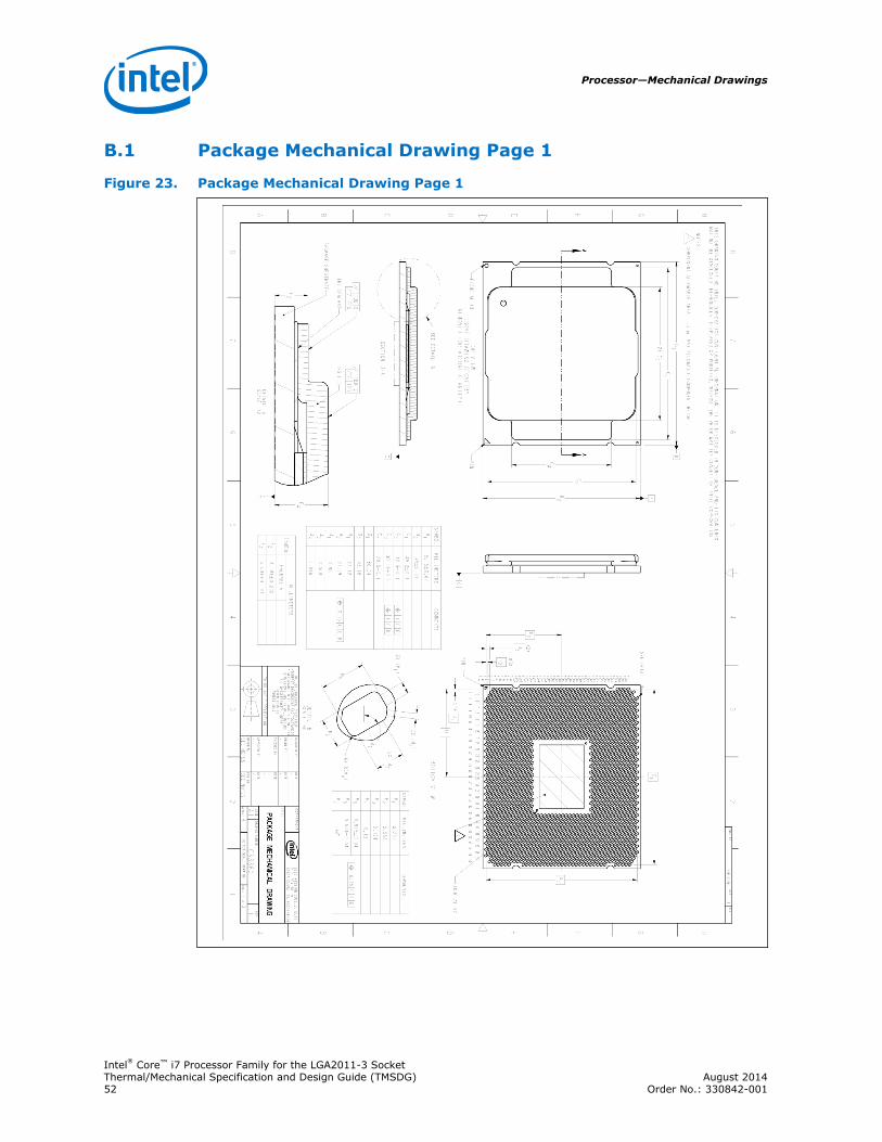
Package Mechanical Drawing Page 1
Figure 23. Package Mechanical Drawing Page 1
B.1
Processor—Mechanical Drawings
Intel® Core™ i7 Processor Family for the LGA2011-3 SocketThermal/Mechanical Specification and Design Guide (TMSDG) August 201452 Order No.: 330842-001
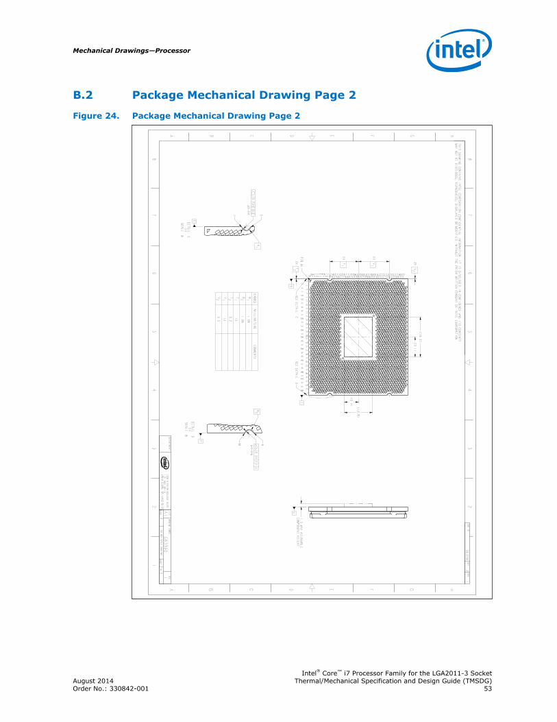
Package Mechanical Drawing Page 2
Figure 24. Package Mechanical Drawing Page 2HGFEDCBA
HGFEDCBA
8 7 6 5
4 3 2
8 7 6 5
4 3 2 1
0.23
CGE
0.23
CFE
(9.1)
(18.2)
(6.4)
(12.8)
2X V1
2X T1
2X V2
2X T2
1.5 MAX ALLOWABLE
COMPONENT HEIGHT
R1
R2
F
G
G
F
C
THIS DRAWING CONTAINS INTEL CORPORATION CONFIDENTIAL INFORMATION. IT IS DISCLOSED IN CONFIDENCE AND ITS CONTENTS
MAY NOT BE DISCLOSED, REPRODUCED, DISPLAYED OR MODIFIED, WITHOUT THE PRIOR WRITTEN CONSENT OF INTEL CORPORATION.
G63360
21
DWG. NO
SHT.
REV
DEPARTMENT
R2200 MISSION COLLEGE BLVD.
P.O. BOX 58119
SANTA CLARA, CA 95052-8119
-
SIZE
DRAWING NUMBER
REV
A1
G63360
1SCALE: 4
DO NOT SCALE DRAWINGSHEET 2
OF 3
1 3 5 7 9 11 13 15 17 19 21 23 25 27 29 31 33 35 37 39 41 43 45 47 49 51 53 55 57
2 4 6 8 10 12 14 16 18 20 22 24 26 28 30 32 34 36 38 40 42 44 46 48 50 52 54 56 58
DF
DE
DD
DC
DB
DA
CY
CW
CT
CU
CV
CR
CP
CL
CM
CN
CK
CJ
CH
CE
CF
CG
CD
CC
BY
CA
CB
BW
BV
BU
BP
BR
BT
BN
BM
BJ
BK
BL
BH
BG
BF
BC
BD
BE
BB
BA
AV
AW
AY
AU
AT
AR
AM
AN
AP
AL
AK
AG
AH
AJ
AF
AE
AD
AA
AB
AC
Y W
T
U
V R
P
N
K
L
M
J
H
E
F
G
D
C
B
A
SEE DETAIL C
SEE DETAIL D
PIN #1
DETAIL C
2X
SCALE 8
J K
JK
DETAIL D
2X
SCALE 8
M NMN
SYMBOL
MILLIMETERS
COMMENTS
R1
1.09
R2
1.09
T1
13
T2
0.2
V1
14
V2
0.2
B.2
Mechanical Drawings—Processor
Intel® Core™ i7 Processor Family for the LGA2011-3 SocketAugust 2014 Thermal/Mechanical Specification and Design Guide (TMSDG)Order No.: 330842-001 53
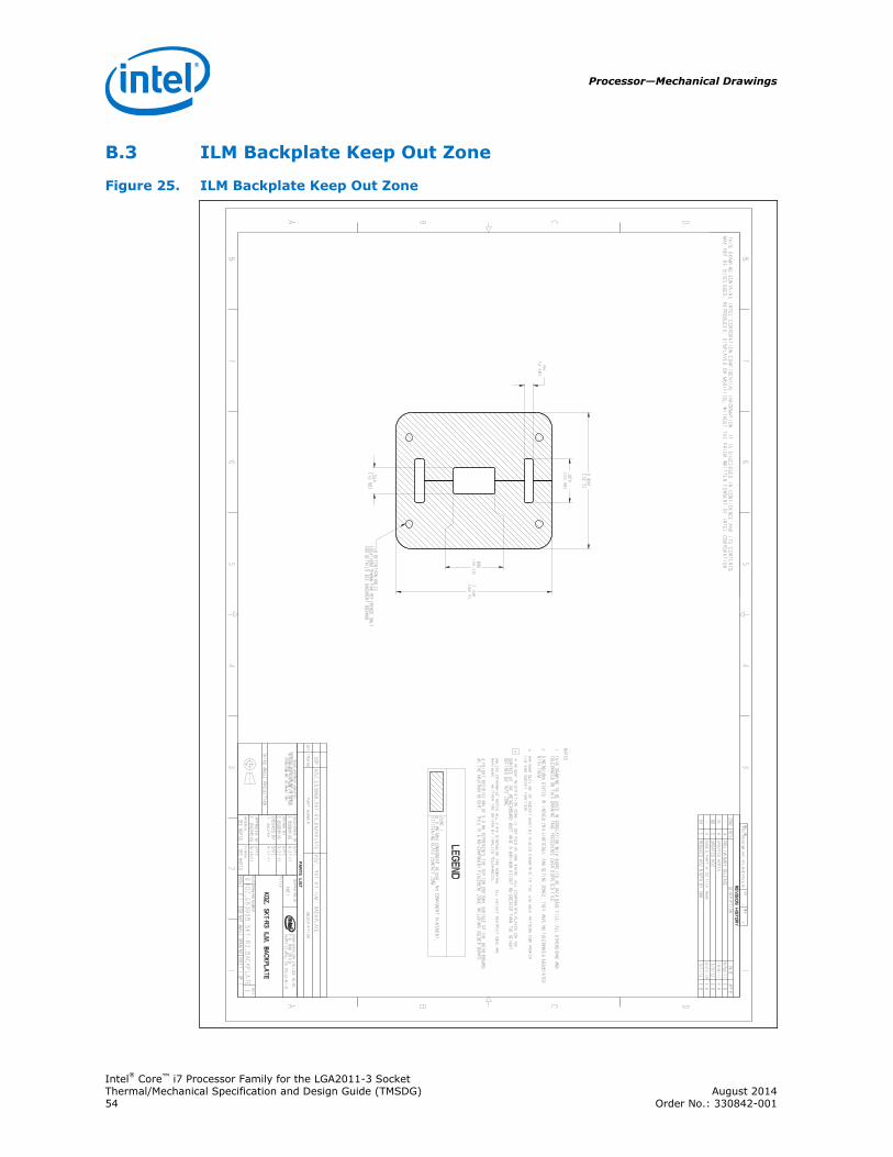
ILM Backplate Keep Out Zone
Figure 25. ILM Backplate Keep Out Zone
13
45
67
8
B C DA
12
34
56
78
B C DA2200 MISSION COLLEGE BLVD.
P.O. BOX 58119
SANTA CLARA, CA 95052-8119
R
2.854
72.5
[]
3.248
82.5
[]
.550
13.98
[]
.880
22.35
[]
.920
23.38
[]
.196
4.98
[]
KOZ_G63998_SKT-R3_BACKPLATE
1E
DWG. NO
SHT.
REV
SHEET 1 OF 1
DO NOT SCALE DRAWINGSCALE: 2:1
EKOZ_G63998_SKT-R3_BACKPLATE
DREV
DRAWING NUMBER
SIZE
KOZ, SKT-R3 ILM, BACKPLATE
TITLE PMCI
DEPARTMENT
SEE NOTES
SEE NOTES
FINISH
MATERIAL
9/30/11
E. BUDDRIUS
DATE
APPROVED BY
--
9-27-11
T. AULAKH
DATE
CHECKED BY
9-27-11
E.BUDDRIUS
DATE
DRAWN BY
9-27-11
E.BUDDRIUS
DATE
DESIGNED BY
UNLESS OTHERWISE SPECIFIED
INTERPRET DIMENSIONS AND TOLERANCES
IN ACCORDANCE WITH ASME Y14.5M-1994
DIMENSIONS ARE IN INCHES (MM)
THIRD ANGLE PROJECTION
PARTS LIST
DESCRIPTION
PART NUMBER
ITEM NOQTY
KOZ, SKT-R3 ILM, BACKPLATE
KOZ_G63998_SKT-R3_BACKPLATE
TOP
REVISION HISTORY
ZONE
REV
DESCRIPTION
DATE
APPR
-A
PRELIMINARY RELEASE
9/30/11
E.B.
2C
BUPDATED NOTES
10/8/11
E.B.
6B
CUPDATED KOZ
2/2/12
E.B.
-D
ADDED PART # TO FILE NAME
3/27/12
E.B.
C6
EREDUCED KOZ WIDTH BY 5MM
5/1/13
E.B.
THIS DRAWING CONTAINS INTEL CORPORATION CONFIDENTIAL INFORMATION. IT IS DISCLOSED IN CONFIDENCE AND ITS CONTENTS
MAY NOT BE DISCLOSED, REPRODUCED, DISPLAYED OR MODIFIED, WITHOUT THE PRIOR WRITTEN CONSENT OF INTEL CORPORATION.
NOTES:
1. THIS DRAWING TO BE USED IN CORELATION WITH SUPPLIED 3D DATA BASE FILE. ALL
DIMENSIONS AND
TOLERANCES ON THIS DRAWING TAKE PRECEDENCE OVER SUPPLIED FILE.
2. DIMENSIONS STATED IN INCHES (MILLIMETERS) AND DEFINE ZONES, THEY HAVE NO
TOLERANCES ASSOCIATED
WITH THEM.
3. MAXIMUM OUTLINE OF SOCKET MUST BE PLACED SYMMETRIC TO THE ILM HOLE PATTERN
FOR PROPER
ILM AND SOCKET FUNCTION.
4 A HEIGHT RESTRICTION ZONE IS DEFINED AS ONE WHERE ALL COMPONENTS PLACED ON
THE
SURFACE OF THE MOTHERBOARD MUST HAVE A MAXIMUM HEIGHT NO GREATER THAN THE
HEIGHT
DEFINED BY THAT ZONE.
UNLESS OTHERWISE NOTED ALL VIEW DIMENSION ARE NOMINAL. ALL HEIGHT
RESTRICTIONS ARE
MAXIMUMS. NEITHER ARE DRIVEN BY IMPLIED TOLERANCES.
A HEIGHT RESTRICTION OF 0.0 MM REPRESENTS THE TOP (OR BOTTOM) SURFACE OF
THE MOTHERBOARD
AS THE MAXIMUM HEIGHT. THIS IS A NO COMPONENT PLACEMENT ZONE INCLUDING
SOLDER BUMPS.
ILM RETENTION HOLES
LOCATIONS SHOWN FOR REFERENCE ONLY
FOR DETAILS SEE DOCUMENT G63999
LEGEND
ZONE 1:
0.0 MM MAX COMPONENT HEIGHT, NO COMPONENT PLACEMENT,
STIFFENING PLATE CONTACT ZONE
B.3
Processor—Mechanical Drawings
Intel® Core™ i7 Processor Family for the LGA2011-3 SocketThermal/Mechanical Specification and Design Guide (TMSDG) August 201454 Order No.: 330842-001
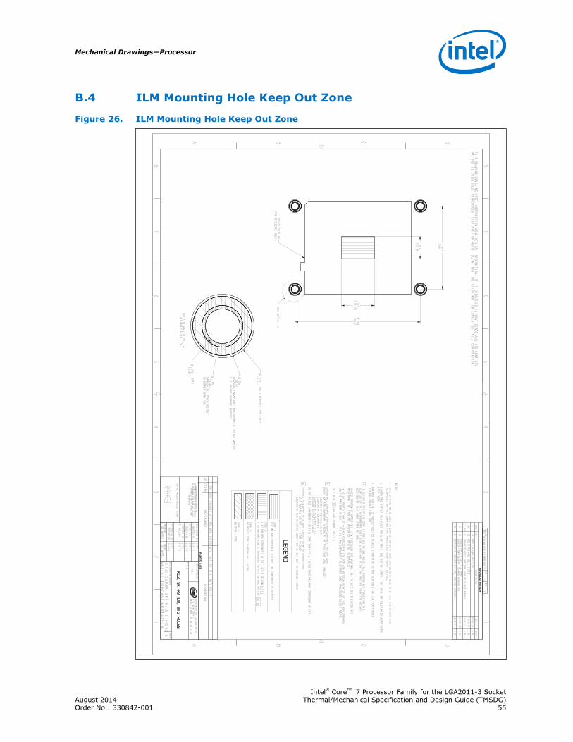
ILM Mounting Hole Keep Out Zone
Figure 26. ILM Mounting Hole Keep Out Zone
13
45
67
8
B C DA
12
34
56
78
B C DA2200 MISSION COLLEGE BLVD.
P.O. BOX 58119
SANTA CLARA, CA 95052-8119
R
1.811
[46]
2.724
[69.2]
.150
NPTH
[3.81]
.256
[6.5]
OD COPPER WEAR PAD: NON-GROUNDED, SOLDER MASKED
0.0" HEIGHT PACKAGE KEEPOUT
.717
[18.2]
.504
[12.8]
.180
[4.57]
THROUGH ALL ROUTE KEEPOUT
ID COPPER WEAR PAD
.276
ROUTE KEEPOUT, TOP LAYER
[7.01]
KOZ_G63999_SKT-R3_MTG-HOLES
1E
DWG. NO
SHT.
REV
SHEET 1 OF 1
DO NOT SCALE DRAWINGSCALE: 3:1
EKOZ_G63999_SKT-R3_MTG-HOLES
DREV
DRAWING NUMBER
SIZE
KOZ, SKT-R3 ILM, MTG HOLES
TITLE PMCI
DEPARTMENT
SEE NOTES
SEE NOTES
FINISH
MATERIAL
9/30/11
E. BUDDRIUS
DATE
APPROVED BY
--
9-27-11
T. AULAKH
DATE
CHECKED BY
9-27-11
E.BUDDRIUS
DATE
DRAWN BY
9-27-11
E.BUDDRIUS
DATE
DESIGNED BY
UNLESS OTHERWISE SPECIFIED
INTERPRET DIMENSIONS AND TOLERANCES
IN ACCORDANCE WITH ASME Y14.5M-1994
DIMENSIONS ARE IN INCHES (MM)
TOLERANCES:
THIRD ANGLE PROJECTION
PARTS LIST
DESCRIPTION
PART NUMBER
ITEM NOQTY
KOZ, SKT-R3 ILM, MTG HOLES
KOZ_G63999_SKT-R3_MTG-HOLES
TOP
REVISION HISTORY
ZONE
REV
DESCRIPTION
DATE
APPR
-A
PRELIMINARY RELEASE
9/27/11
E.B.
A5
BMODIFIED KOZ HOLE SIZES
10/7/11
E.B.
C7,A5
CUPDATED HOLE PATTERN AND KEEP-OUT AREAS
2/2/12
E.B.
B4
DADDED PART # TO FILE NAME
ADDED "TOP LAYER" TO RKO DIMENSION
3/28/12
E.B.
B6
ECORRECTED SOCKET KEYING, NO KOZ CHANGES
8/6/12
E.B.
THIS DRAWING CONTAINS INTEL CORPORATION CONFIDENTIAL INFORMATION. IT IS DISCLOSED IN CONFIDENCE AND ITS CONTENTS
MAY NOT BE DISCLOSED, REPRODUCED, DISPLAYED OR MODIFIED, WITHOUT THE PRIOR WRITTEN CONSENT OF INTEL CORPORATION.
NOTES:
1. THIS DRAWING TO BE USED IN CORELATION WITH SUPPLIED 3D DATA BASE FILE. ALL
DIMENSIONS AND
TOLERANCES ON THIS DRAWING TAKE PRECEDENCE OVER SUPPLIED FILE.
2. DIMENSIONS STATED IN INCHES (MILLIMETERS) AND DEFINE ZONES, THEY HAVE NO
TOLERANCES ASSOCIATED
WITH THEM.
3. MAXIMUM OUTLINE OF SOCKET MUST BE PLACED SYMMETRIC TO THE ILM HOLE PATTERN
FOR PROPER
ILM AND SOCKET FUNCTION.
4 A HEIGHT RESTRICTION ZONE IS DEFINED AS ONE WHERE ALL COMPONENTS PLACED ON
THE
SURFACE OF THE MOTHERBOARD MUST HAVE A MAXIMUM HEIGHT NO GREATER THAN THE
HEIGHT
DEFINED BY THAT ZONE AFTER REFLOW.
UNLESS OTHERWISE NOTED ALL VIEW DIMENSION ARE NOMINAL. ALL HEIGHT
RESTRICTIONS ARE
MAXIMUMS. NEITHER ARE DRIVEN BY IMPLIED TOLERANCES.
A HEIGHT RESTRICTION OF 0.0 MM REPRESENTS THE TOP (OR BOTTOM) SURFACE OF
THE MOTHERBOARD
AS THE MAXIMUM HEIGHT. THIS IS A NO COMPONENT PLACEMENT ZONE INCLUDING
SOLDER BUMPS.
SEE NOTE 5 FOR ADDITIONAL DETAILS.
5 ASSUMING A GENERIC A MAXIMUM COMPONENT HEIGHT ZONE.
CHOICE OF AND COMPONENT PLACEMENT IN THIS ZONE MUST INCLUDE:
- COMPONENT NOMINAL HEIGHT
- COMPONENT TOLERANCES
- COMPONENT PLACEMENT TILT
- SOLDER REFLOW THICKNESS
DO NOT PLACE COMPONENTS IN THIS ZONE THAT WILL EXCEED THIS MAXIMUM COMPONENT
HEIGHT.
6 ASSUMES PLACEMENT OF A 0805 CAPACITOR WITH DIMENSIONS:
- CAP NOMINAL HEIGHT = 1.25MM (0.049")
- COMPONENT MAX MATERIAL CONDITION HEIGHT NOT TO EXCEED 1.50MM.
SEE DETAIL A
SOCKET OUTLINE
FOR REFERENCE ONLY
TOP SIDE HOLE DETAIL A
4 PLACES SCALE 15:1
LEGEND
ZONE 1:
0.0 MM MAX COMPONENT HEIGHT, NO COMPONENT PLACEMENT
ZONE 2:
1.67 MM MAX COMPONENT HEIGHT AFTER REFLOW
4 5
1.50 MM MAX (MMC) COMPONENT HEIGHT BEFORE REFLOW
4 6
ZONE 3:
NO ROUTE ZONE THROUGH ALL LAYERS
ZONE 4:
NO ROUTE ZONE
B.4
Mechanical Drawings—Processor
Intel® Core™ i7 Processor Family for the LGA2011-3 SocketAugust 2014 Thermal/Mechanical Specification and Design Guide (TMSDG)Order No.: 330842-001 55
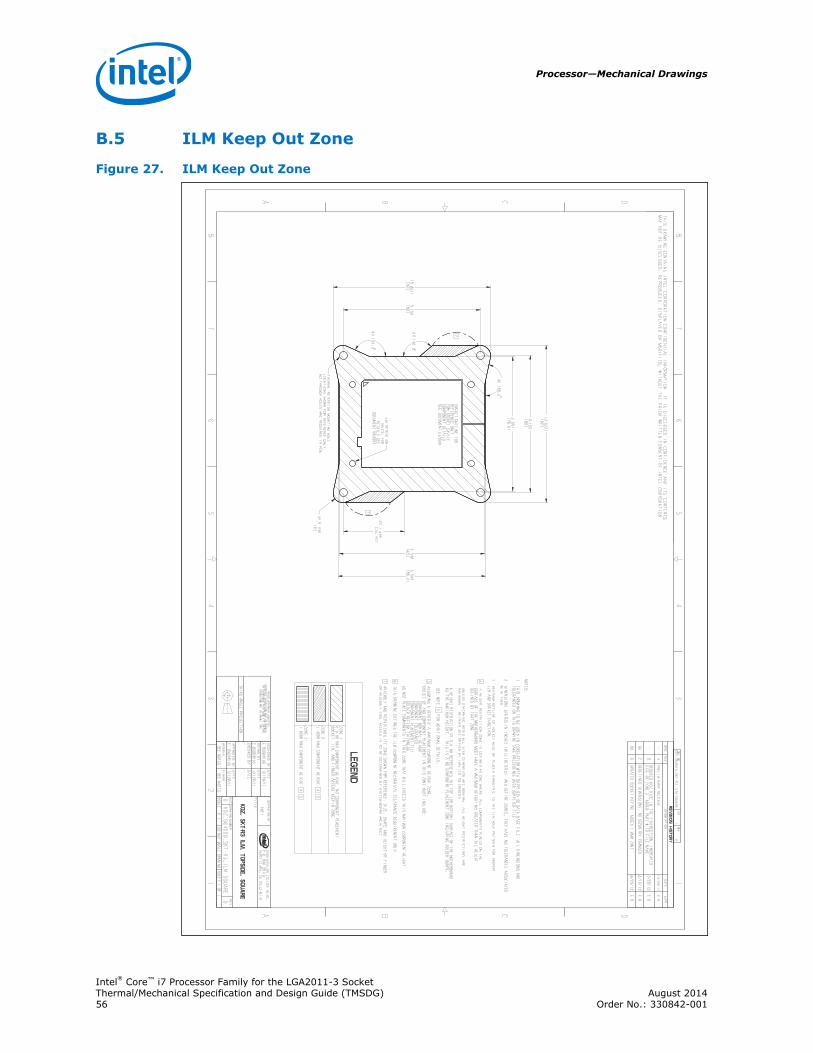
ILM Keep Out Zone
Figure 27. ILM Keep Out Zone
13
45
67
8
B C DA
12
34
56
78
B C DA2200 MISSION COLLEGE BLVD.
P.O. BOX 58119
SANTA CLARA, CA 95052-8119
R
3.091
[78.5]
(3.622)
[92]
3.346
[85]
(3.622)
[92]
3.150
[80]
3.150
[80]
4X 168.2
4X R.236
[6]
4X 154.3
2X 1.406
[35.72]
2X 140.0
3.394
[86.2]
KOZ_G64000_SKT-R3_ILM-SQUARE
1D
DWG. NO
SHT.
REV
SHEET 1 OF 1
DO NOT SCALE DRAWINGSCALE: 2:1
DKOZ_G64000_SKT-R3_ILM-SQUARE
DREV
DRAWING NUMBER
SIZE
KOZ, SKT-R3 ILM, TOPSIDE, SQUARE
TITLE PMCI
DEPARTMENT
SEE NOTES
SEE NOTES
FINISH
MATERIAL
12/29/11
E. BUDDRIUS
DATE
APPROVED BY
--
--
DATE
CHECKED BY
12/29/11
E.BUDDRIUS
DATE
DRAWN BY
12/29/11
E.BUDDRIUS
DATE
DESIGNED BY
UNLESS OTHERWISE SPECIFIED
INTERPRET DIMENSIONS AND TOLERANCES
IN ACCORDANCE WITH ASME Y14.5M-1994
DIMENSIONS ARE IN INCHES (MM)
THIRD ANGLE PROJECTION
REVISION HISTORY
ZONE
REV
DESCRIPTION
DATE
APPR
-A
PRELIMINARY RELEASE
12/29/11
E.B.
-B
REDUCED KOZ SIZE IN THE Y-DIRECTION, INCREASED
SIZE OF ZONE 2, ADDED PART # TO FILE NAME
3/28/12
E.B.
B6
CREDEFINED DIMENSIONS, NO GEOMETRY CHANGED
4/12/12
E.B.
B6
DUPDATED SOCKET KEYING, ADDED 1.6MM ZONE
8/29/12
E.B.
THIS DRAWING CONTAINS INTEL CORPORATION CONFIDENTIAL INFORMATION. IT IS DISCLOSED IN CONFIDENCE AND ITS CONTENTS
MAY NOT BE DISCLOSED, REPRODUCED, DISPLAYED OR MODIFIED, WITHOUT THE PRIOR WRITTEN CONSENT OF INTEL CORPORATION.
NOTES:
1. THIS DRAWING TO BE USED IN CORELATION WITH SUPPLIED 3D DATA BASE FILE. ALL
DIMENSIONS AND
TOLERANCES ON THIS DRAWING TAKE PRECEDENCE OVER SUPPLIED FILE.
2. DIMENSIONS STATED IN INCHES (MILLIMETERS) AND DEFINE ZONES, THEY HAVE NO
TOLERANCES ASSOCIATED
WITH THEM.
3. MAXIMUM OUTLINE OF SOCKET MUST BE PLACED SYMMETRIC TO THE ILM HOLE PATTERN
FOR PROPER
ILM AND SOCKET FUNCTION.
4 A HEIGHT RESTRICTION ZONE IS DEFINED AS ONE WHERE ALL COMPONENTS PLACED ON
THE
SURFACE OF THE MOTHERBOARD MUST HAVE A MAXIMUM HEIGHT NO GREATER THAN THE
HEIGHT
DEFINED BY THAT ZONE.
UNLESS OTHERWISE NOTED ALL VIEW DIMENSION ARE NOMINAL. ALL HEIGHT
RESTRICTIONS ARE
MAXIMUMS. NEITHER ARE DRIVEN BY IMPLIED TOLERANCES.
A HEIGHT RESTRICTION OF 0.0 MM REPRESENTS THE TOP (OR BOTTOM) SURFACE OF
THE MOTHERBOARD
AS THE MAXIMUM HEIGHT. THIS IS A NO COMPONENT PLACEMENT ZONE INCLUDING
SOLDER BUMPS.
SEE NOTE 5 FOR ADDITIONAL DETAILS.
5 ASSUMING A GENERIC A MAXIMUM COMPONENT HEIGHT ZONE.
CHOICE OF AND COMPONENT PLACEMENT IN THIS ZONE MUST INCLUDE:
- COMPONENT NOMINAL HEIGHT
- COMPONENT TOLERANCES
- COMPONENT PLACEMENT TILT
- SOLDER REFLOW THICKNESS
DO NOT PLACE COMPONENTS IN THIS ZONE THAT WILL EXCEED THIS MAXIMUM COMPONENT
HEIGHT.
6 THIS DRAWING DEFINES THE ILM COMPONENT MECHANICAL CLEARANCE REQUIREMENT ONLY.
7 ASSEMBLY AND SERVICEABILITY ZONE SHOWN FOR REFERENCE. SIZE, SHAPE AND HEIGHT
OF FINGER
OR ASSEMBLY TOOL ACCESS IS TO BE DETERMINED BY SYSTEM/BOARD ARCHITECT.
7
SOCKET OUTLINE FOR
REFERENCE ONLY
FOR SOCKET CAVITY
COMPONENT DETAILS
SEE DOCUMENT G63999
7
ILM RETENTION
HOLES, FOR
DETAILS SEE
DOCUMENT G63999
THERMAL RETENTION MOUNTING HOLE
LOCATIONS SHOWN FOR REFERENCE ONLY,
NO THROUGH HOLES ARE REQUIRED IN PCB
LEGEND
ZONE 1:
0.0 MM MAX COMPONENT HEIGHT, NO COMPONENT PLACEMENT,
SOCKET, ILM, AND FINGER ACCESS KEEPIN ZONE
ZONE 2:
1.40MM MAX COMPONENT HEIGHT
4 5
ZONE 3:
1.60MM MAX COMPONENT HEIGHT
4 5
B.5
Processor—Mechanical Drawings
Intel® Core™ i7 Processor Family for the LGA2011-3 SocketThermal/Mechanical Specification and Design Guide (TMSDG) August 201456 Order No.: 330842-001
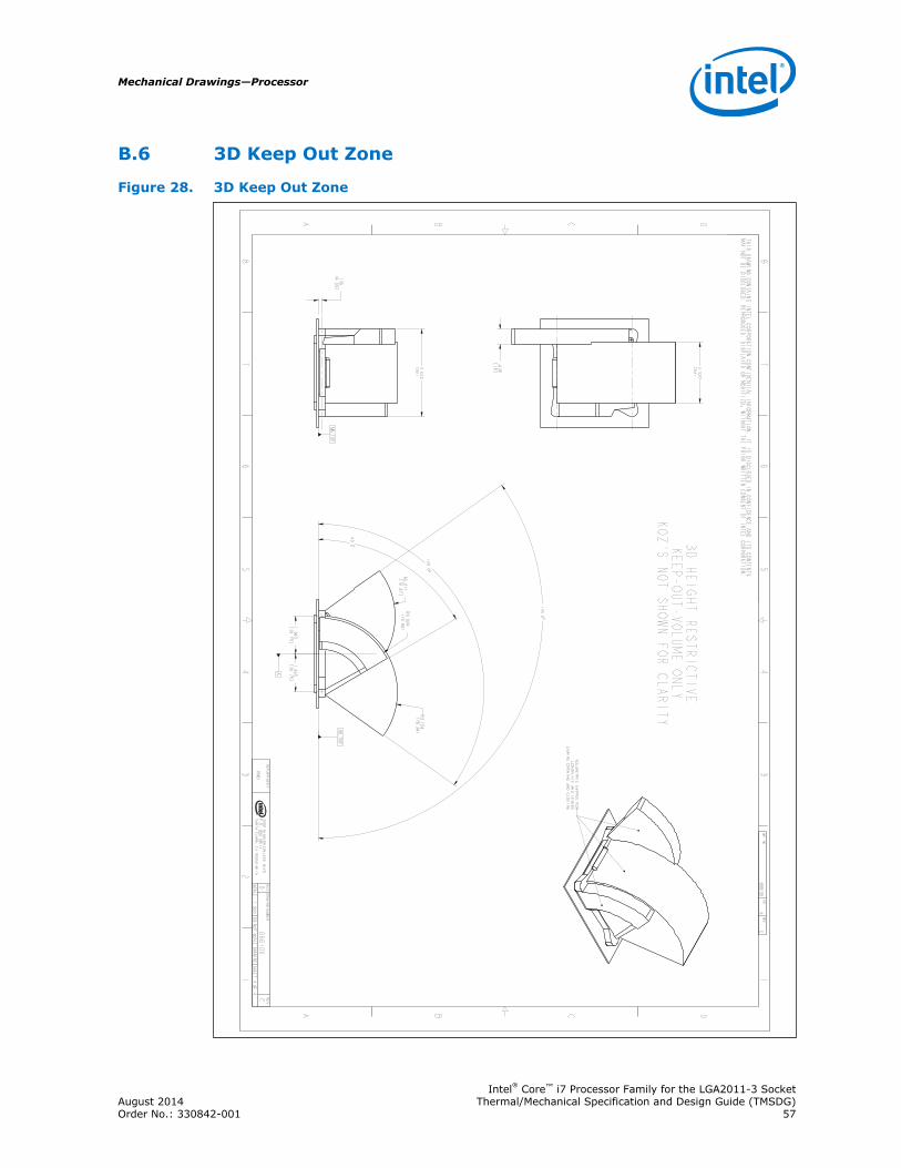
3D Keep Out Zone
Figure 28. 3D Keep Out Zone
13
45
67
8
B C DA
12
34
56
78
B C DA
2200 MISSION COLLEGE BLVD.
P.O. BOX 58119
SANTA CLARA, CA 95052-8119
R
MB_TOP
MB_TOP
A
.159
[4.03]
3.622
[92]
2.520
[64]
.630
[16]
60.0
125.0
125.0
R3.124
[79.36]
R3.011
[76.47]
R3.024
[76.82]1.565
[39.75]
1.565
[39.75]
G66106
4C
DWG. NO
SHT.
REV
THIS DRAWING CONTAINS INTEL CORPORATION CONFIDENTIAL INFORMATION. IT IS DISCLOSED IN CONFIDENCE AND ITS CONTENTS
MAY NOT BE DISCLOSED, REPRODUCED, DISPLAYED OR MODIFIED, WITHOUT THE PRIOR WRITTEN CONSENT OF INTEL CORPORATION.
SHEET 4 OF 4
DO NOT SCALE DRAWINGSCALE: 1.000
PMCI
CG66106
DREV
DRAWING NUMBER
SIZEDEPARTMENT
3D HEIGHT RESTRICTIVE
KEEP-OUT-VOLUME ONLY
KOZ'S NOT SHOWN FOR CLARITY
VOLUMETRIC SWPPES FOR
LOADPLATE AND LEVERS
DURING OPENING AND CLOSING
B.6
Mechanical Drawings—Processor
Intel® Core™ i7 Processor Family for the LGA2011-3 SocketAugust 2014 Thermal/Mechanical Specification and Design Guide (TMSDG)Order No.: 330842-001 57