Embed Size (px)
Citation preview
Integrating EVs into the Smart-GridResults of the EU co-funded FP7 project “PowerUp”
Andras KovacsBroadBit
Dave MarplesTechnolution
Robert SchmidtDENSO AUTOMOTIVE Dtld. GmbH
Raduz MorsztynCorinex Communications
Abstract— Standardization efforts are currently underway to realize the Europe-wide deployment of Smart-Grids. Numerous protocols have already been standardized; each tailored to a distinct application domains. Amongst these, Smart Metering and EV charging have only recently started to converge, and the goal of the PowerUp project has been to advance such convergence. This paper presents the major results from the project. The PowerUp consortium has specified and developed an end-to-end EV to Grid communication system, respecting the applicable communications standards. After introducing the underlying system architecture for the end-to-end integration of the Vehicle-to-Grid (V2G) communications interface, we describe critical Smart-Grid integration aspects for each protocol layer within the V2G communications protocol stack. Finally, prototype test observations are presented.
Keywords—EV to Grid communication; V2G communication interface; Smart Metering infrastructure; PLC technologies; Interoperability.
I. INTRODUCTION
Preparing for the mass market deployment of EVs requires the development of an Vehicle to Grid (V2G) communication system for managing the EV recharging sessions to allow grid balancing and the correlated demands causing overloads. The standardization of an interoperable V2G communications interface is ongoing in the ISO/IEC 15118 working group [2]. This standard defines the communications interface between the EV and the local recharging controller device. On the automotive side of the V2G interface proprietary integration with the battery management and HMI components, usually over CAN or a similar bus structure, integrates the recharging functionality into the vehicle. On the grid side, integration with existing and upcoming Smart-Grid technologies is the key for a successful introduction of an EV to Grid communication system. These integrations, on the vehicle and grid sides, are the focus of PowerUp, and this article.
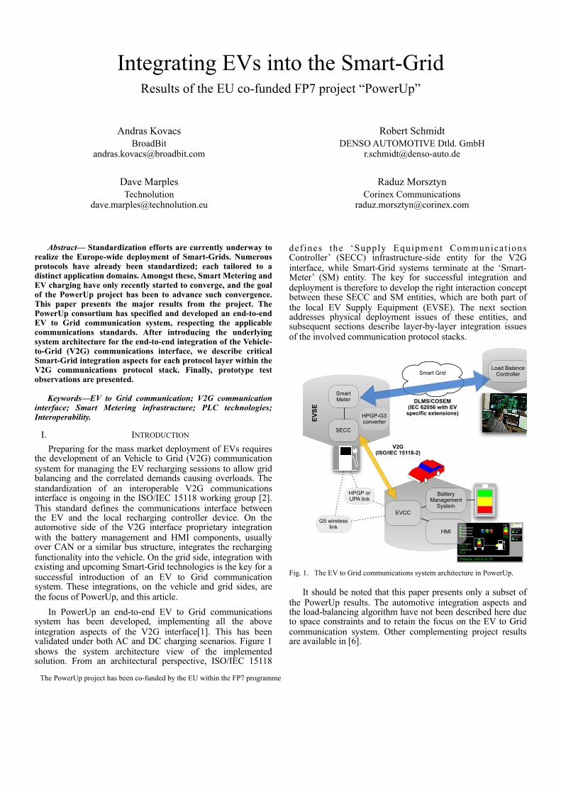
In PowerUp an end-to-end EV to Grid communications system has been developed, implementing all the above integration aspects of the V2G interface[1]. This has been validated under both AC and DC charging scenarios. Figure 1 shows the system architecture view of the implemented solution. From an architectural perspective, ISO/IEC 15118
def ines the ‘Supply Equipment Communicat ions Controller’ (SECC) infrastructure-side entity for the V2G interface, while Smart-Grid systems terminate at the ‘Smart-Meter’ (SM) entity. The key for successful integration and deployment is therefore to develop the right interaction concept between these SECC and SM entities, which are both part of the local EV Supply Equipment (EVSE). The next section addresses physical deployment issues of these entities, and subsequent sections describe layer-by-layer integration issues of the involved communication protocol stacks.
HPGP or UPA link
Smart Grid
DLMS/COSEM(IEC 62056 with EV
specific extensions)
V2G(ISO/IEC 15118-2)
EVCC
Battery Management
System
WSU statusON
B&M statusON
VOLTAGE(V)278 VCURRENT(A)20 A
Charging…End at 11:30
Battery
25%
AlarmsGeneral FaultBattery FaultDC/DC FaultMotor/Inverter
HMI
Load Balance Controller
G5 wireless link
SECC
Smart Meter
HPGP-G3 converterEV
SE
Fig. 1. The EV to Grid communications system architecture in PowerUp.
It should be noted that this paper presents only a subset of the PowerUp results. The automotive integration aspects and the load-balancing algorithm have not been described here due to space constraints and to retain the focus on the EV to Grid communication system. Other complementing project results are available in [6].
The PowerUp project has been co-funded by the EU within the FP7 programme
II. PHYSICAL DEPLOYMENT OF THE V2G INFRASTRUCTURE
A. Deployment for private recharging stationsConsequent to the EU Smart Metering directive [4], nearly
all EU households shall be equipped with a SM over the next five or six years. Most Smart Meters have remotely upgradeable firmware, and could thus conceivably be upgraded to incorporate a SECC entity, subject to CPU and memory constraints. While currently deployed SMs are mostly using narrowband S-FSK PLC technology, the next wave of SMs is expected to exploit OFDM-modulated PLC technologies. Dual-mode G3/PRIME chipsets under development, as well as the superior capabilities of such OFDM links in comparison with S-FSK, mean that SMs are expected to converge towards G3/PRIME or a subsequent standards-based PLC communication model. However, ISO/IEC 15118-3 specifies the ‘HomePlug GreenPhy’ (HPGP) technology for the PLC link in the V2G interface and so an issue of physical layer compatibility and interoperability arises and cost constraints make it unlikely that SMs include any EV-specific additional hardware. A solution to this problem would be to use a bridge between different media in the wall-box outlet installed for the EV power cable. This wallbox would then bridge the SM-specific and EV-specific PLC links. Such a HPGP-to-G3 media bridge has been prototyped in PowerUp, and is shown in Figure 2. Sufficient miniaturization has been already achieved, and its size can be easily reduced further in subsequent product development for incorporation into the envisaged wall-box outlet.
Fig. 2. HPGP-to-G3 PLC media bridge.
B. Deployment for public charging spotsThe deployment of a significant number of EV charging
spots is already underway both across the EU and globally. Eventually these charging spots must be retrofitted with an EV to Grid communication system to allow them to participate in the smart grid model. The PowerUp project has demonstrated the compact implementation of the additional components required for such a migration, which can be fitted into commercial EV charging spots. Figure 3 shows an example for such retrofitting.
Fig. 3. Retrofitting of a public recharging spot for EV to Grid comms.
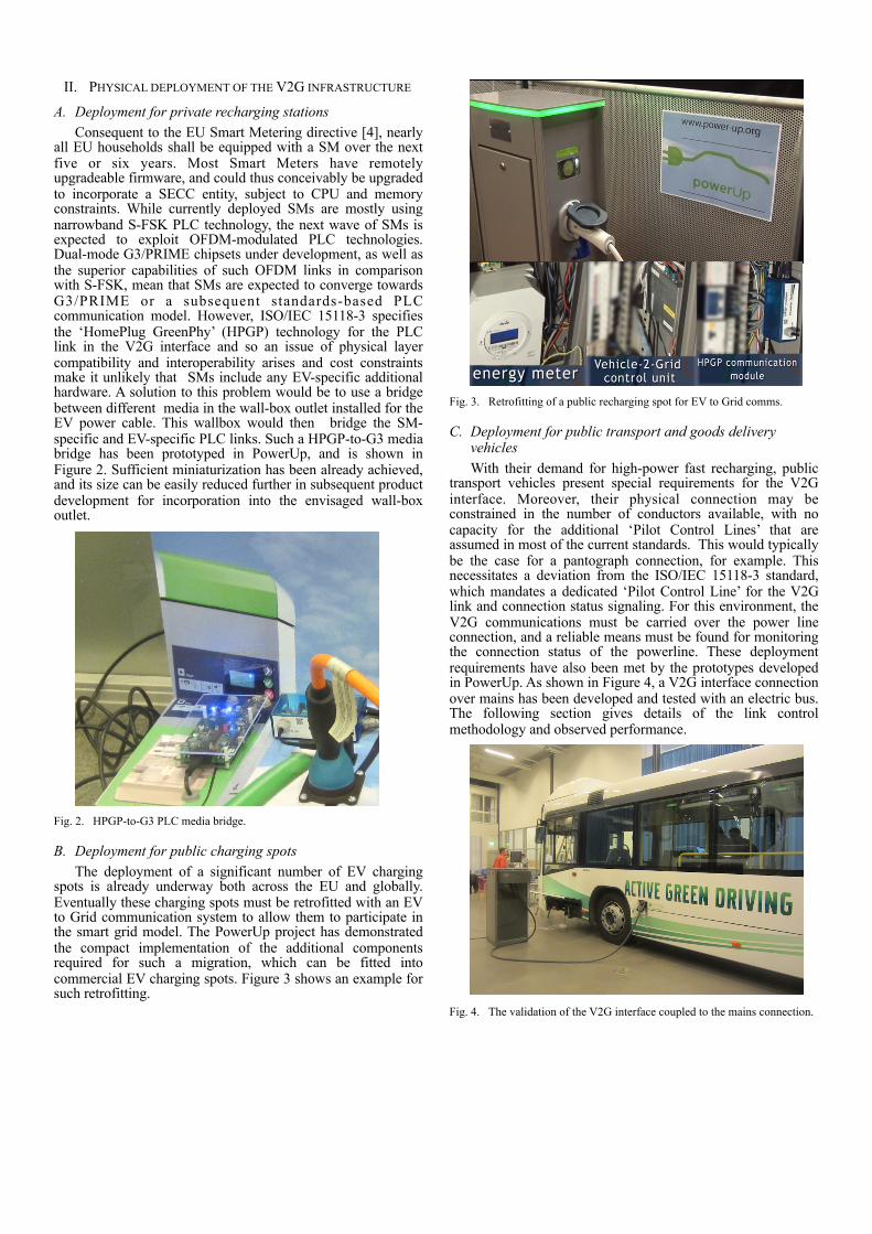
C. Deployment for public transport and goods delivery vehiclesWith their demand for high-power fast recharging, public
transport vehicles present special requirements for the V2G interface. Moreover, their physical connection may be constrained in the number of conductors available, with no capacity for the additional ‘Pilot Control Lines’ that are assumed in most of the current standards. This would typically be the case for a pantograph connection, for example. This necessitates a deviation from the ISO/IEC 15118-3 standard, which mandates a dedicated ‘Pilot Control Line’ for the V2G link and connection status signaling. For this environment, the V2G communications must be carried over the power line connection, and a reliable means must be found for monitoring the connection status of the powerline. These deployment requirements have also been met by the prototypes developed in PowerUp. As shown in Figure 4, a V2G interface connection over mains has been developed and tested with an electric bus. The following section gives details of the link control methodology and observed performance.
Fig. 4. The validation of the V2G interface coupled to the mains connection.
III. LINK LAYER INTEGRATION OF THE V2G INTERFACE
A. PLC link performanceA QCA7000 chip based HPGP modem has been developed
for establishing the ISO/IEC 15118-3 compliant PLC link. This device has been used with the default link control settings, along with a Marvell 9500 series chipset based UPA modem which has been used for analysis and comparison of HPGP to the established broadband over powerline Smart Grid system.
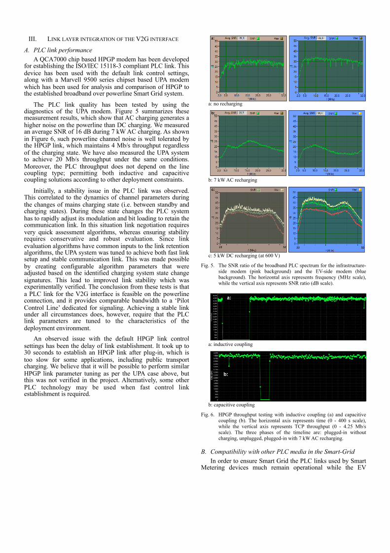
The PLC link quality has been tested by using the diagnostics of the UPA modem. Figure 5 summarizes these measurement results, which show that AC charging generates a higher noise on the powerline than DC charging. We measured an average SNR of 16 dB during 7 kW AC charging. As shown in Figure 6, such powerline channel noise is well tolerated by the HPGP link, which maintains 4 Mb/s throughput regardless of the charging state. We have also measured the UPA system to achieve 20 Mb/s throughput under the same conditions. Moreover, the PLC throughput does not depend on the line coupling type; permitting both inductive and capacitive coupling solutions according to other deployment constraints.
Initially, a stability issue in the PLC link was observed. This correlated to the dynamics of channel parameters during the changes of mains charging state (i.e. between standby and charging states). During these state changes the PLC system has to rapidly adjust its modulation and bit loading to retain the communication link. In this situation link negotiation requires very quick assessment algorithms, whereas ensuring stability requires conservative and robust evaluation. Since link evaluation algorithms have common inputs to the link retention algorithms, the UPA system was tuned to achieve both fast link setup and stable communication link. This was made possible by creating configurable algorithm parameters that were adjusted based on the identified charging system state change signatures. This lead to improved link stability which was experimentally verified. The conclusion from these tests is that a PLC link for the V2G interface is feasible on the powerline connection, and it provides comparable bandwidth to a ‘Pilot Control Line’ dedicated for signaling. Achieving a stable link under all circumstances does, however, require that the PLC link parameters are tuned to the characteristics of the deployment environment.
An observed issue with the default HPGP link control settings has been the delay of link establishment. It took up to 30 seconds to establish an HPGP link after plug-in, which is too slow for some applications, including public transport charging. We believe that it will be possible to perform similar HPGP link parameter tuning as per the UPA case above, but this was not verified in the project. Alternatively, some other PLC technology may be used when fast control link establishment is required.
a: no recharging
b: 7 kW AC recharging
c: 5 kW DC recharging (at 600 V)
Fig. 5. The SNR ratio of the broadband PLC spectrum for the infrastructure-side modem (pink background) and the EV-side modem (blue background). The horizontal axis represents frequency (MHz scale), while the vertical axis represents SNR ratio (dB scale).
a: inductive coupling
b: capacitive coupling
Fig. 6. HPGP throughput testing with inductive coupling (a) and capacitive coupling (b). The horizontal axis represents time (0 - 400 s scale), while the vertical axis represents TCP throughput (0 - 4.25 Mb/s scale). The three phases of the timeline are: plugged-in without charging, unplugged, plugged-in with 7 kW AC recharging.
B. Compatibility with other PLC media in the Smart-GridIn order to ensure Smart Grid the PLC links used by Smart
Metering devices much remain operational while the EV
charging equipment is in use. This has been verified by measuring the throughput of a G3 PLC link, having one modem at the recharging spot, while the EV is recharging using AC technology. We measured 50 kb/s throughput on the G3 link regardless of the EV charging status. While this is a promising result, it must be noted that the link attenuation between the two G3 modems was very low due to the short distance between them modems, and that no conductive noise was imposed due to the isolated setup. A future follow-up test could be to measure the G3 link performance during EV recharging while attenuating the G3 link for emulating the proper distance of the remote side, and exposing it to the unfiltered grid. It is appropriate that this kind of testing is performed in a Field Operational Test (FOT) environment rather than the limited trial environment of the PowerUp project.
IV.NETWORK AND TRANSPORT LAYER INTEGRATION WITH THE GRID INFRASTRUCTURE
The networking topology of the end-to-end EV to Grid communications system can be described as a sequence of two connections:
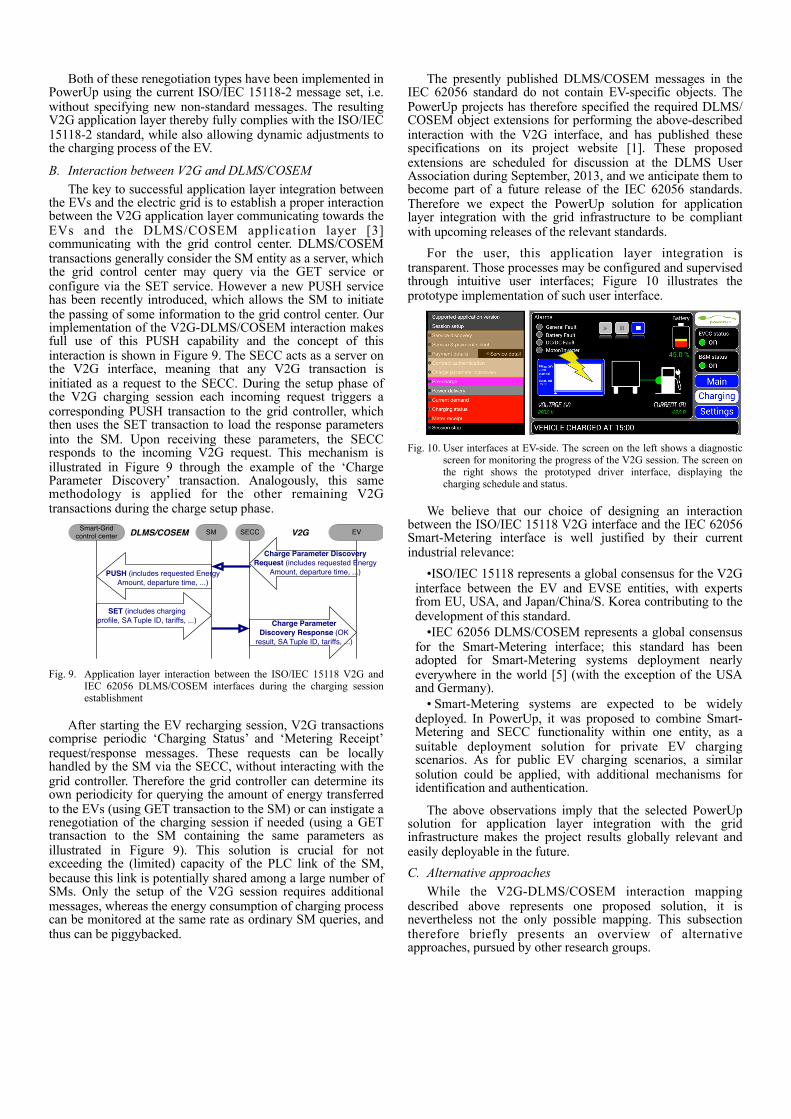
a) EV to SECC connection: This uses UDP transport with link-local IPv6 multicast addressing to distribute the SECC Discovery Protocol messages. It uses TLS with unicast IPv6 addressing to deliver the V2G application messages. Figure 7 summarizes this protocol stack. The sequence of the protocol setup is described in the annex.
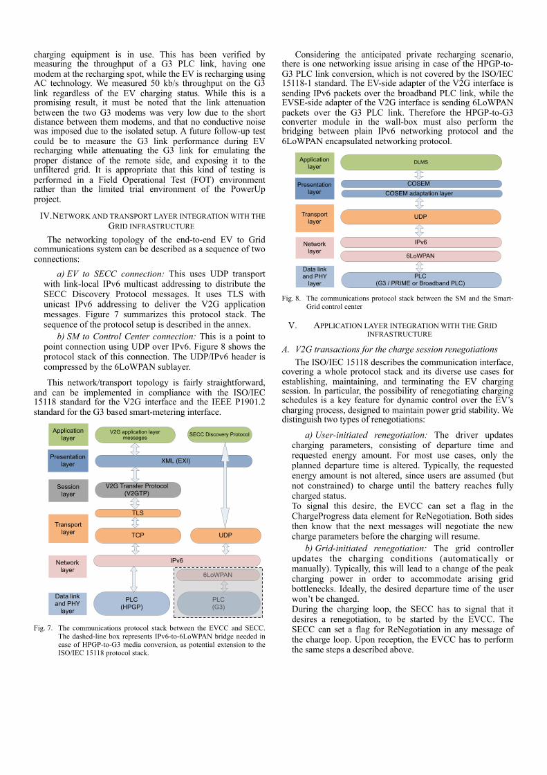
b) SM to Control Center connection: This is a point to point connection using UDP over IPv6. Figure 8 shows the protocol stack of this connection. The UDP/IPv6 header is compressed by the 6LoWPAN sublayer.
This network/transport topology is fairly straightforward, and can be implemented in compliance with the ISO/IEC 15118 standard for the V2G interface and the IEEE P1901.2 standard for the G3 based smart-metering interface.
Data link and PHY
layer
Network layer
Transport layer
Session layer
Presentation layer
Application layer
TCP
TLS
V2G application layer messages SECC Discovery Protocol
PLC (HPGP)
IPv6
XML (EXI)
V2G Transfer Protocol (V2GTP)
UDP
PLC (G3)
6LoWPAN
Fig. 7. The communications protocol stack between the EVCC and SECC. The dashed-line box represents IPv6-to-6LoWPAN bridge needed in case of HPGP-to-G3 media conversion, as potential extension to the ISO/IEC 15118 protocol stack.
Considering the anticipated private recharging scenario, there is one networking issue arising in case of the HPGP-to-G3 PLC link conversion, which is not covered by the ISO/IEC 15118-1 standard. The EV-side adapter of the V2G interface is sending IPv6 packets over the broadband PLC link, while the EVSE-side adapter of the V2G interface is sending 6LoWPAN packets over the G3 PLC link. Therefore the HPGP-to-G3 converter module in the wall-box must also perform the bridging between plain IPv6 networking protocol and the 6LoWPAN encapsulated networking protocol.
Data link and PHY
layer
Network layer
Transport layer
Presentation layer
Application layer
DLMS
IPv6
COSEM
UDP
6LoWPAN
COSEM adaptation layer
PLC (G3 / PRIME or Broadband PLC)
Fig. 8. The communications protocol stack between the SM and the Smart-Grid control center
V. APPLICATION LAYER INTEGRATION WITH THE GRID INFRASTRUCTURE
A. V2G transactions for the charge session renegotiationsThe ISO/IEC 15118 describes the communication interface,
covering a whole protocol stack and its diverse use cases for establishing, maintaining, and terminating the EV charging session. In particular, the possibility of renegotiating charging schedules is a key feature for dynamic control over the EV’s charging process, designed to maintain power grid stability. We distinguish two types of renegotiations:
a) User-initiated renegotiation: The driver updates charging parameters, consisting of departure time and requested energy amount. For most use cases, only the planned departure time is altered. Typically, the requested energy amount is not altered, since users are assumed (but not constrained) to charge until the battery reaches fully charged status.To signal this desire, the EVCC can set a flag in the ChargeProgress data element for ReNegotiation. Both sides then know that the next messages will negotiate the new charge parameters before the charging will resume.
b) Grid-initiated renegotiation: The grid controller updates the charging conditions (automatically or manually). Typically, this will lead to a change of the peak charging power in order to accommodate arising grid bottlenecks. Ideally, the desired departure time of the user won’t be changed.During the charging loop, the SECC has to signal that it desires a renegotiation, to be started by the EVCC. The SECC can set a flag for ReNegotiation in any message of the charge loop. Upon reception, the EVCC has to perform the same steps a described above.
Both of these renegotiation types have been implemented in PowerUp using the current ISO/IEC 15118-2 message set, i.e. without specifying new non-standard messages. The resulting V2G application layer thereby fully complies with the ISO/IEC 15118-2 standard, while also allowing dynamic adjustments to the charging process of the EV.
B. Interaction between V2G and DLMS/COSEMThe key to successful application layer integration between
the EVs and the electric grid is to establish a proper interaction between the V2G application layer communicating towards the EVs and the DLMS/COSEM application layer [3] communicating with the grid control center. DLMS/COSEM transactions generally consider the SM entity as a server, which the grid control center may query via the GET service or configure via the SET service. However a new PUSH service has been recently introduced, which allows the SM to initiate the passing of some information to the grid control center. Our implementation of the V2G-DLMS/COSEM interaction makes full use of this PUSH capability and the concept of this interaction is shown in Figure 9. The SECC acts as a server on the V2G interface, meaning that any V2G transaction is initiated as a request to the SECC. During the setup phase of the V2G charging session each incoming request triggers a corresponding PUSH transaction to the grid controller, which then uses the SET transaction to load the response parameters into the SM. Upon receiving these parameters, the SECC responds to the incoming V2G request. This mechanism is illustrated in Figure 9 through the example of the ‘Charge Parameter Discovery’ transaction. Analogously, this same methodology is applied for the other remaining V2G transactions during the charge setup phase.
Smart-Grid control center SM SECC EV
SET (includes charging profile, SA Tuple ID, tariffs, ...)
V2GDLMS/COSEM
Charge Parameter Discovery Response (OK
result, SA Tuple ID, tariffs, ...)
PUSH (includes requested Energy Amount, departure time, ...)
Charge Parameter Discovery Request (includes requested Energy
Amount, departure time, ...)
Fig. 9. Application layer interaction between the ISO/IEC 15118 V2G and IEC 62056 DLMS/COSEM interfaces during the charging session establishment
After starting the EV recharging session, V2G transactions comprise periodic ‘Charging Status’ and ‘Metering Receipt’ request/response messages. These requests can be locally handled by the SM via the SECC, without interacting with the grid controller. Therefore the grid controller can determine its own periodicity for querying the amount of energy transferred to the EVs (using GET transaction to the SM) or can instigate a renegotiation of the charging session if needed (using a GET transaction to the SM containing the same parameters as illustrated in Figure 9). This solution is crucial for not exceeding the (limited) capacity of the PLC link of the SM, because this link is potentially shared among a large number of SMs. Only the setup of the V2G session requires additional messages, whereas the energy consumption of charging process can be monitored at the same rate as ordinary SM queries, and thus can be piggybacked.
The presently published DLMS/COSEM messages in the IEC 62056 standard do not contain EV-specific objects. The PowerUp projects has therefore specified the required DLMS/COSEM object extensions for performing the above-described interaction with the V2G interface, and has published these specifications on its project website [1]. These proposed extensions are scheduled for discussion at the DLMS User Association during September, 2013, and we anticipate them to become part of a future release of the IEC 62056 standards. Therefore we expect the PowerUp solution for application layer integration with the grid infrastructure to be compliant with upcoming releases of the relevant standards.
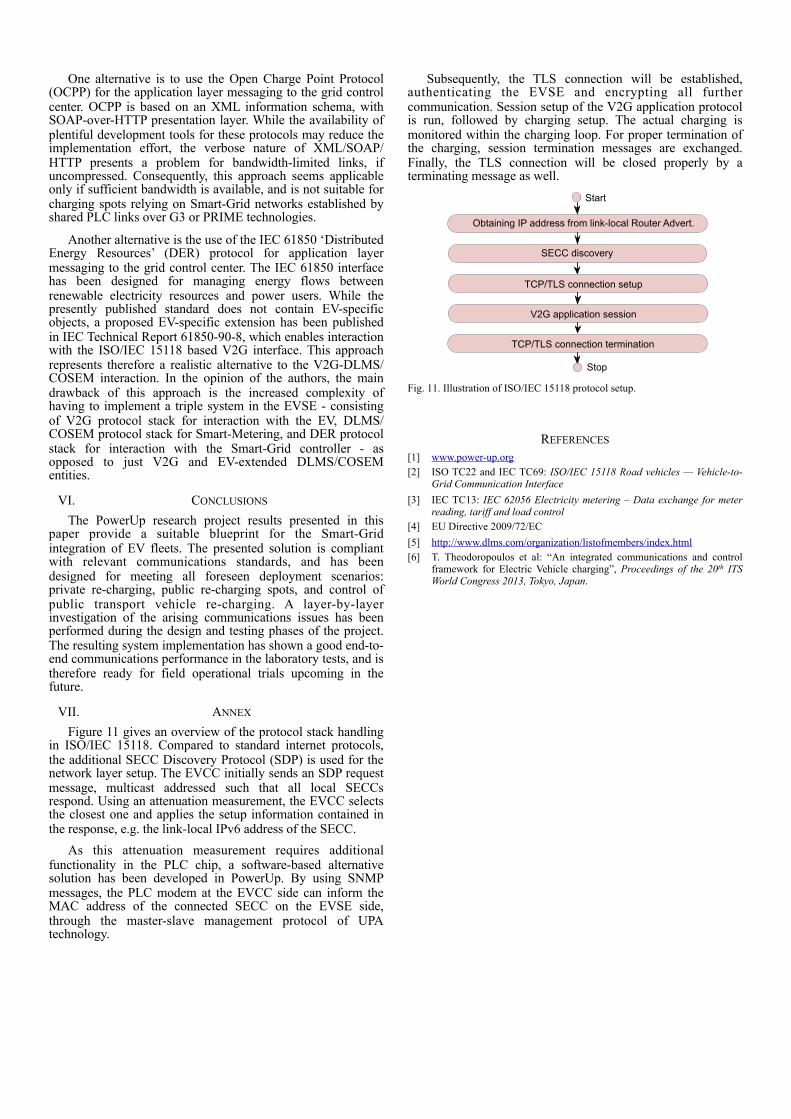
For the user, this application layer integration is transparent. Those processes may be configured and supervised through intuitive user interfaces; Figure 10 illustrates the prototype implementation of such user interface.
Fig. 10. User interfaces at EV-side. The screen on the left shows a diagnostic
screen for monitoring the progress of the V2G session. The screen on the right shows the prototyped driver interface, displaying the charging schedule and status.
We believe that our choice of designing an interaction between the ISO/IEC 15118 V2G interface and the IEC 62056 Smart-Metering interface is well justified by their current industrial relevance:
•ISO/IEC 15118 represents a global consensus for the V2G interface between the EV and EVSE entities, with experts from EU, USA, and Japan/China/S. Korea contributing to the development of this standard.
•IEC 62056 DLMS/COSEM represents a global consensus for the Smart-Metering interface; this standard has been adopted for Smart-Metering systems deployment nearly everywhere in the world [5] (with the exception of the USA and Germany).
• Smart-Metering systems are expected to be widely deployed. In PowerUp, it was proposed to combine Smart-Metering and SECC functionality within one entity, as a suitable deployment solution for private EV charging scenarios. As for public EV charging scenarios, a similar solution could be applied, with additional mechanisms for identification and authentication.
The above observations imply that the selected PowerUp solution for application layer integration with the grid infrastructure makes the project results globally relevant and easily deployable in the future.C. Alternative approaches
While the V2G-DLMS/COSEM interaction mapping described above represents one proposed solution, it is nevertheless not the only possible mapping. This subsection therefore briefly presents an overview of alternative approaches, pursued by other research groups.
One alternative is to use the Open Charge Point Protocol (OCPP) for the application layer messaging to the grid control center. OCPP is based on an XML information schema, with SOAP-over-HTTP presentation layer. While the availability of plentiful development tools for these protocols may reduce the implementation effort, the verbose nature of XML/SOAP/HTTP presents a problem for bandwidth-limited links, if uncompressed. Consequently, this approach seems applicable only if sufficient bandwidth is available, and is not suitable for charging spots relying on Smart-Grid networks established by shared PLC links over G3 or PRIME technologies.
Another alternative is the use of the IEC 61850 ‘Distributed Energy Resources’ (DER) protocol for application layer messaging to the grid control center. The IEC 61850 interface has been designed for managing energy flows between renewable electricity resources and power users. While the presently published standard does not contain EV-specific objects, a proposed EV-specific extension has been published in IEC Technical Report 61850-90-8, which enables interaction with the ISO/IEC 15118 based V2G interface. This approach represents therefore a realistic alternative to the V2G-DLMS/COSEM interaction. In the opinion of the authors, the main drawback of this approach is the increased complexity of having to implement a triple system in the EVSE - consisting of V2G protocol stack for interaction with the EV, DLMS/COSEM protocol stack for Smart-Metering, and DER protocol stack for interaction with the Smart-Grid controller - as opposed to just V2G and EV-extended DLMS/COSEM entities.
VI. CONCLUSIONS
The PowerUp research project results presented in this paper provide a suitable blueprint for the Smart-Grid integration of EV fleets. The presented solution is compliant with relevant communications standards, and has been designed for meeting all foreseen deployment scenarios: private re-charging, public re-charging spots, and control of public transport vehicle re-charging. A layer-by-layer investigation of the arising communications issues has been performed during the design and testing phases of the project. The resulting system implementation has shown a good end-to-end communications performance in the laboratory tests, and is therefore ready for field operational trials upcoming in the future.
VII. ANNEX
Figure 11 gives an overview of the protocol stack handling in ISO/IEC 15118. Compared to standard internet protocols, the additional SECC Discovery Protocol (SDP) is used for the network layer setup. The EVCC initially sends an SDP request message, multicast addressed such that all local SECCs respond. Using an attenuation measurement, the EVCC selects the closest one and applies the setup information contained in the response, e.g. the link-local IPv6 address of the SECC.
As this attenuation measurement requires additional functionality in the PLC chip, a software-based alternative solution has been developed in PowerUp. By using SNMP messages, the PLC modem at the EVCC side can inform the MAC address of the connected SECC on the EVSE side, through the master-slave management protocol of UPA technology.
Subsequently, the TLS connection will be established, authenticating the EVSE and encrypting all further communication. Session setup of the V2G application protocol is run, followed by charging setup. The actual charging is monitored within the charging loop. For proper termination of the charging, session termination messages are exchanged. Finally, the TLS connection will be closed properly by a terminating message as well.
SECC discovery
Obtaining IP address from link-local Router Advert.
TCP/TLS connection setup
V2G application session
TCP/TLS connection termination
Start
Stop
Fig. 11. Illustration of ISO/IEC 15118 protocol setup.
REFERENCES[1] www.power-up.org[2] ISO TC22 and IEC TC69: ISO/IEC 15118 Road vehicles — Vehicle-to-
Grid Communication Interface[3] IEC TC13: IEC 62056 Electricity metering – Data exchange for meter
reading, tariff and load control[4] EU Directive 2009/72/EC[5] http://www.dlms.com/organization/listofmembers/index.html[6] T. Theodoropoulos et al: “An integrated communications and control
framework for Electric Vehicle charging”, Proceedings of the 20th ITS World Congress 2013, Tokyo, Japan.