Embed Size (px)
Citation preview
D
C H A P T E R 10
Integrating Cisco Unity Connection 9.x with the Phone SystemA phone system integration enables communication between Cisco Unity Connection and the phone system, providing users with the following features:
• Calls to a user extension that does not answer are forwarded to the personal greeting of the user.
• Calls to a user extension that is busy are forwarded to the busy greeting of the user.
• Connection receives caller ID information from the phone system (if available).
• A user has easy access to messages by pressing a button on the phone and entering a password.
• Connection identifies the user who leaves a message during a forwarded internal call, based on the extension from which the call originated.
• Messages left for a user activate the message waiting indicator (MWI) on the extension.
See the following sections for detailed information:
• How a Phone System Integration Works, page 10-2
• General Integration Issues, page 10-9
• Deployment Models for Integrations with Cisco Unified Communications Manager, page 10-10
• Deploying Phones Across the WAN, page 10-10
• Integrating with Cisco Unified Communications Manager (by Using SCCP or SIP), page 10-10
• Integrating with Cisco Unified Communications Manager Express (by Using SCCP or SIP), page 10-19
• Integrating Cisco Unity Connection with Multiple Versions of Cisco Unified Communications Manager and Cisco Unified Communications Manager Express, page 10-21
• Integrating Cisco Unity Connection with Cisco Unified Survivable Remote Site Telephony (Cisco Unified SRST), page 10-21
• Survivable Remote Site Voicemail, page 10-24
• Integrating by Using SIP, page 10-25
• Integrating with Circuit-Switched Phone Systems by Using PIMG or TIMG Units, page 10-26
• Integrating with Multiple Phone Systems, page 10-29
• Integrating Cisco Unity Connection with a QSIG-Enabled Phone System by Using Cisco ISR Voice Gateways, page 10-31
• Links to Additional Integration Information, page 10-31
10-1esign Guide for Cisco Unity Connection Release 9.x
Chapter 10 Integrating Cisco Unity Connection 9.x with the Phone SystemHow a Phone System Integration Works
How a Phone System Integration WorksA phone system integration depends on the following components to be successful:
• Lines and cables necessary to make physical connections (for PIMG/TIMG integrations) or a network connection (in Cisco Unified Communications Manager, Cisco Unified Communications Manager Express, SIP proxy servers, and QSIG-enabled phone systems). Depending on the type of integration, the phone system connects through different combinations of lines. See the applicable section for more information:
– Integration with Cisco Unified Communications Manager, page 10-2
– Digital Integration with Digital PIMG Units, page 10-3
– DTMF Integration with Analog PIMG Units, page 10-3
– Serial (SMDI, MCI, or MD-110) Integration with Analog PIMG Units, page 10-4
– TIMG Serial (SMDI, MCI, or MD-110) Integration, page 10-4
– TIMG In-Band Integration, page 10-5
– PIMG/TIMG Integrations and Cisco Unified Communications Manager Through Cisco Unified SIP Proxy, page 10-6
• Settings in the phone system and in Connection. For more information, see the “Settings in the Phone System and in Cisco Unity Connection” section on page 10-7.
• Call information exchanged by the phone system and Connection. For more information, see the “Call Information Exchanged by the Phone System and Cisco Unity Connection” section on page 10-7.
• Call control (signals used to set up, monitor, and tear down a call) to determine and control the status of the call. For more information, see the “Call Control” section on page 10-8.
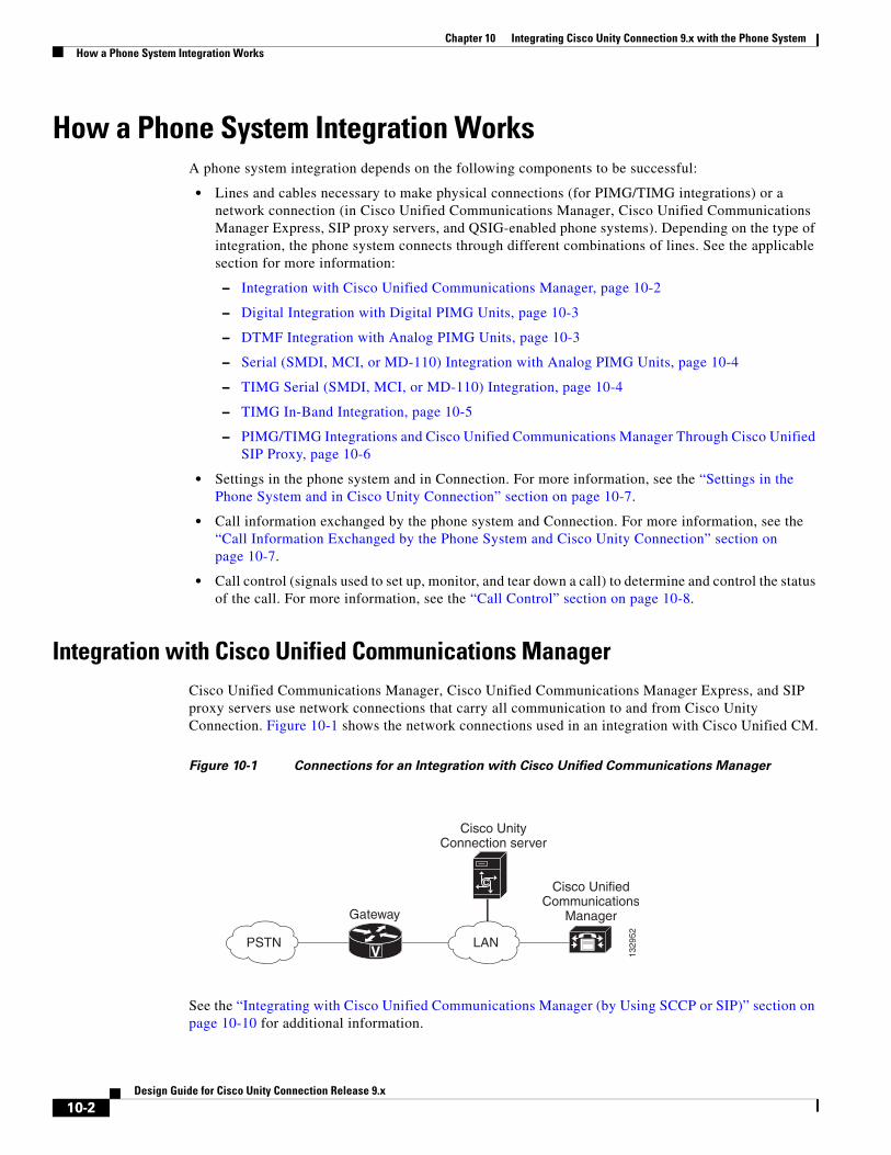
Integration with Cisco Unified Communications ManagerCisco Unified Communications Manager, Cisco Unified Communications Manager Express, and SIP proxy servers use network connections that carry all communication to and from Cisco Unity Connection. Figure 10-1 shows the network connections used in an integration with Cisco Unified CM.
Figure 10-1 Connections for an Integration with Cisco Unified Communications Manager
See the “Integrating with Cisco Unified Communications Manager (by Using SCCP or SIP)” section on page 10-10 for additional information.
Gateway
V
Cisco UnifiedCommunications
Manager
LANPSTN
1329
52
C
Cisco UnityConnection server
10-2Design Guide for Cisco Unity Connection Release 9.x
Chapter 10 Integrating Cisco Unity Connection 9.x with the Phone SystemHow a Phone System Integration Works
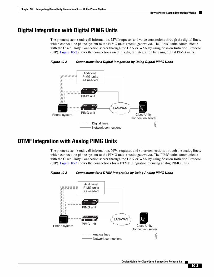
Digital Integration with Digital PIMG UnitsThe phone system sends call information, MWI requests, and voice connections through the digital lines, which connect the phone system to the PIMG units (media gateways). The PIMG units communicate with the Cisco Unity Connection server through the LAN or WAN by using Session Initiation Protocol (SIP). Figure 10-2 shows the connections used in a digital integration by using digital PIMG units.
Figure 10-2 Connections for a Digital Integration by Using Digital PIMG Units
DTMF Integration with Analog PIMG UnitsThe phone system sends call information, MWI requests, and voice connections through the analog lines, which connect the phone system to the PIMG units (media gateways). The PIMG units communicate with the Cisco Unity Connection server through the LAN or WAN by using Session Initiation Protocol (SIP). Figure 10-3 shows the connections for a DTMF integration by using analog PIMG units.
Figure 10-3 Connections for a DTMF Integration by Using Analog PIMG Units
Digital linesNetwork connections
Phone system
1329
53
LAN/WANPIMG unit
AdditionalPIMG unitsas needed
PIMG unit
C
Cisco UnityConnection server
Analog linesNetwork connections
Phone system
1439
84
LAN/WANPIMG unit
AdditionalPIMG unitsas needed
PIMG unit
C
Cisco UnityConnection server
10-3Design Guide for Cisco Unity Connection Release 9.x
Chapter 10 Integrating Cisco Unity Connection 9.x with the Phone SystemHow a Phone System Integration Works
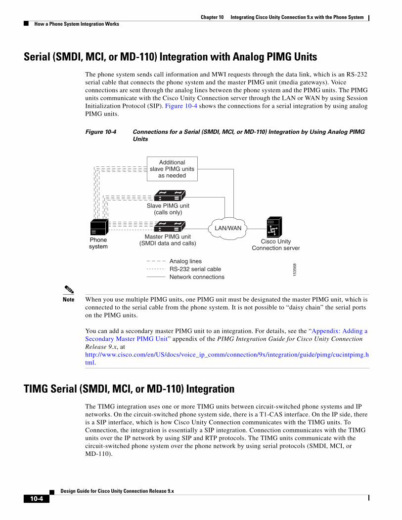
Serial (SMDI, MCI, or MD-110) Integration with Analog PIMG UnitsThe phone system sends call information and MWI requests through the data link, which is an RS-232 serial cable that connects the phone system and the master PIMG unit (media gateways). Voice connections are sent through the analog lines between the phone system and the PIMG units. The PIMG units communicate with the Cisco Unity Connection server through the LAN or WAN by using Session Initialization Protocol (SIP). Figure 10-4 shows the connections for a serial integration by using analog PIMG units.
Figure 10-4 Connections for a Serial (SMDI, MCI, or MD-110) Integration by Using Analog PIMG
Units
Note When you use multiple PIMG units, one PIMG unit must be designated the master PIMG unit, which is connected to the serial cable from the phone system. It is not possible to “daisy chain” the serial ports on the PIMG units.
You can add a secondary master PIMG unit to an integration. For details, see the “Appendix: Adding a Secondary Master PIMG Unit” appendix of the PIMG Integration Guide for Cisco Unity Connection Release 9.x, at http://www.cisco.com/en/US/docs/voice_ip_comm/connection/9x/integration/guide/pimg/cucintpimg.html.
TIMG Serial (SMDI, MCI, or MD-110) IntegrationThe TIMG integration uses one or more TIMG units between circuit-switched phone systems and IP networks. On the circuit-switched phone system side, there is a T1-CAS interface. On the IP side, there is a SIP interface, which is how Cisco Unity Connection communicates with the TIMG units. To Connection, the integration is essentially a SIP integration. Connection communicates with the TIMG units over the IP network by using SIP and RTP protocols. The TIMG units communicate with the circuit-switched phone system over the phone network by using serial protocols (SMDI, MCI, or MD-110).
Analog linesRS-232 serial cableNetwork connections 15
3568
LAN/WANMaster PIMG unit
(SMDI data and calls)
Additionalslave PIMG units
as needed
Slave PIMG unit(calls only)
C
Cisco UnityConnection server
Phonesystem
10-4Design Guide for Cisco Unity Connection Release 9.x
Chapter 10 Integrating Cisco Unity Connection 9.x with the Phone SystemHow a Phone System Integration Works
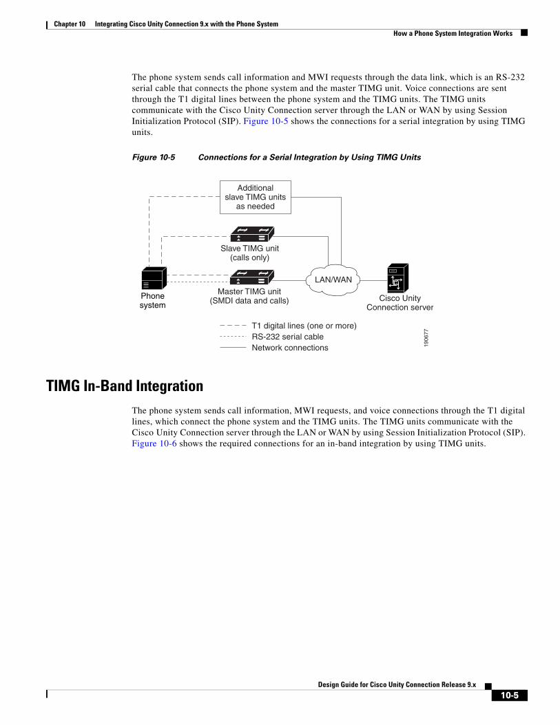
The phone system sends call information and MWI requests through the data link, which is an RS-232 serial cable that connects the phone system and the master TIMG unit. Voice connections are sent through the T1 digital lines between the phone system and the TIMG units. The TIMG units communicate with the Cisco Unity Connection server through the LAN or WAN by using Session Initialization Protocol (SIP). Figure 10-5 shows the connections for a serial integration by using TIMG units.
Figure 10-5 Connections for a Serial Integration by Using TIMG Units
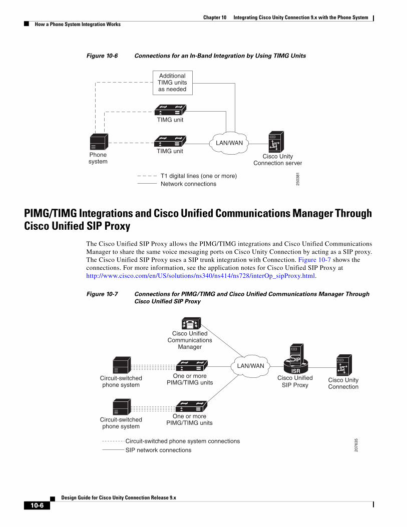
TIMG In-Band IntegrationThe phone system sends call information, MWI requests, and voice connections through the T1 digital lines, which connect the phone system and the TIMG units. The TIMG units communicate with the Cisco Unity Connection server through the LAN or WAN by using Session Initialization Protocol (SIP). Figure 10-6 shows the required connections for an in-band integration by using TIMG units.
T1 digital lines (one or more)RS-232 serial cableNetwork connections 19
0677
LAN/WANMaster TIMG unit
(SMDI data and calls)
Additionalslave TIMG units
as needed
Slave TIMG unit(calls only)
C
Cisco UnityConnection server
Phonesystem
10-5Design Guide for Cisco Unity Connection Release 9.x
Chapter 10 Integrating Cisco Unity Connection 9.x with the Phone SystemHow a Phone System Integration Works
Figure 10-6 Connections for an In-Band Integration by Using TIMG Units
PIMG/TIMG Integrations and Cisco Unified Communications Manager Through Cisco Unified SIP Proxy
The Cisco Unified SIP Proxy allows the PIMG/TIMG integrations and Cisco Unified Communications Manager to share the same voice messaging ports on Cisco Unity Connection by acting as a SIP proxy. The Cisco Unified SIP Proxy uses a SIP trunk integration with Connection. Figure 10-7 shows the connections. For more information, see the application notes for Cisco Unified SIP Proxy at http://www.cisco.com/en/US/solutions/ns340/ns414/ns728/interOp_sipProxy.html.
Figure 10-7 Connections for PIMG/TIMG and Cisco Unified Communications Manager Through
Cisco Unified SIP Proxy25
0381
LAN/WAN C
Cisco UnityConnection server
Phonesystem
T1 digital lines (one or more)Network connections
TIMG unit
TIMG unit
AdditionalTIMG unitsas needed
Circuit-switchedphone system
2076
35
One or morePIMG/TIMG units
Cisco UnifiedCommunications
Manager
ISR
IP
Circuit-switchedphone system
One or morePIMG/TIMG units
Cisco UnifiedSIP Proxy
LAN/WAN
Circuit-switched phone system connections
SIP network connections
C
Cisco UnityConnection
10-6Design Guide for Cisco Unity Connection Release 9.x
Chapter 10 Integrating Cisco Unity Connection 9.x with the Phone SystemHow a Phone System Integration Works
Settings in the Phone System and in Cisco Unity ConnectionFor an integration to be successful, Cisco Unity Connection and the phone system must know the connections to use (for example, IP addresses and channels) and the expected method of communication (for example, IP packets, serial packets, and DTMF tones). Certain integrations require specific codes or extensions for turning MWIs on and off.
There are required settings for Connection, and programming for the phone system, that must be made in order to enable the integration. For information on these settings, see the applicable Cisco Unity Connection integration guide at http://www.cisco.com/en/US/products/ps6509/products_installation_and_configuration_guides_list.html.
Call Information Exchanged by the Phone System and Cisco Unity ConnectionThe phone system and Cisco Unity Connection exchange call information to manage calls and to make the integration features possible. With each call, the following call information is typically passed between the phone system and Connection:
• The extension of the called party.
• The extension of the calling party (for internal calls) or the phone number of the calling party (if it is an external call and the phone system supports caller ID).
• The reason for the forward (the extension is busy, does not answer, or is set to forward all calls). There is also a reason code for Direct Calls.
Cisco Unified Communications Manager SCCP and SIP trunk integrations can also provide the following call information:
• Called number
• First redirecting number
• Last redirecting number
Note Connection can use either the first redirecting number or last redirecting number, depending on the setting of the Use Last (Rather than First) Redirecting Number for Routing Incoming Call check box on the System Settings > Advanced > Conversations page in Cisco Unity Connection Administration.
If the phone system sends the necessary information and if Connection is configured correctly, an integration can provide the following integration functionality:
• Call forward to personal greeting
• Call forward to busy greeting
• Caller ID
• Easy message access (a user can retrieve messages without entering an ID because Connection identifies the user based on the extension from which the call originated; a password may be required)
• Identified user messaging (Connection identifies the user who leaves a message during a forwarded internal call, based on the extension from which the call originated)
10-7Design Guide for Cisco Unity Connection Release 9.x

Chapter 10 Integrating Cisco Unity Connection 9.x with the Phone SystemHow a Phone System Integration Works
Call ControlThe phone system uses a set of signals to set up, monitor, and release connections for a call. Cisco Unity Connection monitors call control signals to determine the state of the call, and uses these signals to respond appropriately to phone system actions and to communicate with the phone system. For example, a caller who is recording a message might hang up, so Connection detects that the call has ended and stops recording.
Depending on the phone system, the following types of call control signals are used:
Note If Extension A calls Extension B and if the Display Name or ASCII Alerting Name of Extension B contains the word "Vociemail", then the call arrives on Cisco Unity Connection as a Direct Call rather than as a forwarded Call.
.Sample Path for a Call from the Phone System to a UserThe following steps give an overview of a sample path that an external call can take when traveling from the phone system to a user.
1. For Cisco Unified Communications Manager, when an external call arrives, the gateway sends the call over the LAN or WAN to Cisco Unified CM. Cisco Unified CM routes the call to the Cisco Unity Connection voice mail pilot number.
For circuit-switched phone systems, when an external call arrives via the PSTN, TI/PRI, DID or LS/GS analog trunks, the phone system routes the call to the Cisco Unity Connection voice mail pilot number.
2. The phone system routes the call to an available Cisco Unity Connection voice messaging port.
3. Connection answers the call and plays the opening greeting.
4. During the opening greeting, the caller enters an extension. For example, the caller enters 1234 to reach a person at that extension.
5. Connection notifies the phone system that there is a call for extension 1234.
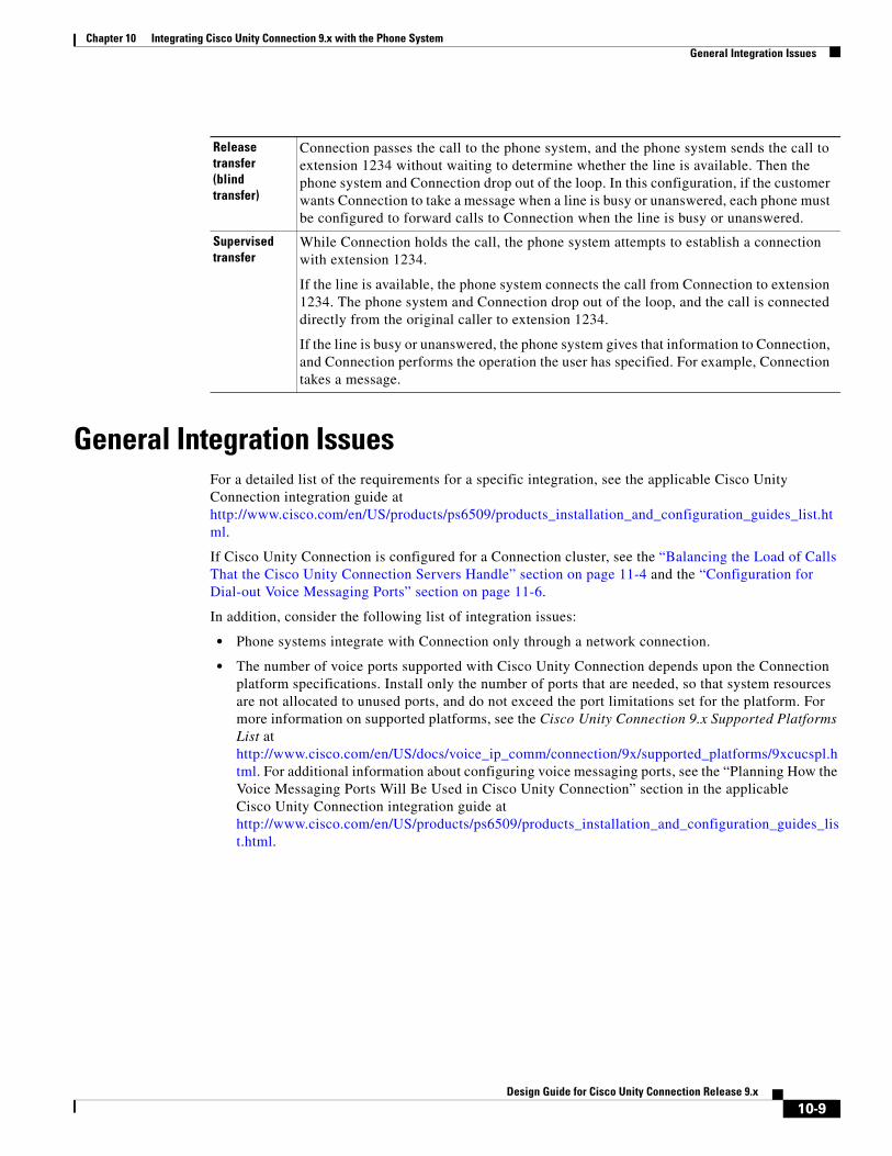
6. Depending on whether Connection is set up to perform a release transfer or a supervised transfer, the following occurs:
Cisco Unified Communications Manager For Skinny Call Control Protocol (SCCP) integrations, Cisco Unified Communications Manager generates SCCP messages, which are translated by Cisco Unity Connection.
For SIP trunk integrations, Cisco Unified CM sends SIP messages, and Connection sends SIP responses when a call is set up or terminated.
Circuit-switched phone system through PIMG/TIMG units
The phone system sends messages to the PIMG or TIMG units (media gateways), which send the applicable SIP messages to Connection. Connection sends SIP responses when a call is set up or terminated, and the PIMG or TIMG units communicate with the phone system.
10-8Design Guide for Cisco Unity Connection Release 9.x
Chapter 10 Integrating Cisco Unity Connection 9.x with the Phone SystemGeneral Integration Issues
General Integration IssuesFor a detailed list of the requirements for a specific integration, see the applicable Cisco Unity Connection integration guide at http://www.cisco.com/en/US/products/ps6509/products_installation_and_configuration_guides_list.html.
If Cisco Unity Connection is configured for a Connection cluster, see the “Balancing the Load of Calls That the Cisco Unity Connection Servers Handle” section on page 11-4 and the “Configuration for Dial-out Voice Messaging Ports” section on page 11-6.
In addition, consider the following list of integration issues:
• Phone systems integrate with Connection only through a network connection.
• The number of voice ports supported with Cisco Unity Connection depends upon the Connection platform specifications. Install only the number of ports that are needed, so that system resources are not allocated to unused ports, and do not exceed the port limitations set for the platform. For more information on supported platforms, see the Cisco Unity Connection 9.x Supported Platforms List at http://www.cisco.com/en/US/docs/voice_ip_comm/connection/9x/supported_platforms/9xcucspl.html. For additional information about configuring voice messaging ports, see the “Planning How the Voice Messaging Ports Will Be Used in Cisco Unity Connection” section in the applicable Cisco Unity Connection integration guide at http://www.cisco.com/en/US/products/ps6509/products_installation_and_configuration_guides_list.html.
Release transfer (blind transfer)
Connection passes the call to the phone system, and the phone system sends the call to extension 1234 without waiting to determine whether the line is available. Then the phone system and Connection drop out of the loop. In this configuration, if the customer wants Connection to take a message when a line is busy or unanswered, each phone must be configured to forward calls to Connection when the line is busy or unanswered.
Supervised transfer
While Connection holds the call, the phone system attempts to establish a connection with extension 1234.
If the line is available, the phone system connects the call from Connection to extension 1234. The phone system and Connection drop out of the loop, and the call is connected directly from the original caller to extension 1234.
If the line is busy or unanswered, the phone system gives that information to Connection, and Connection performs the operation the user has specified. For example, Connection takes a message.
10-9Design Guide for Cisco Unity Connection Release 9.x
Chapter 10 Integrating Cisco Unity Connection 9.x with the Phone SystemDeployment Models for Integrations with Cisco Unified Communications Manager
Deployment Models for Integrations with Cisco Unified Communications Manager
Cisco Unity Connection and Cisco Unified Communications Manager deployment models, including single-site messaging, centralized messaging, and distributed messaging, can be combined to suit customer requirements. When choosing a deployment model, you must consider a range of issues, for example:
• Centralized messaging allows you to consolidate servers and administration, but requires that you plan for access to voice messages in the event of WAN outages and that you perform the appropriate QOS/capacity planning for voice-messaging traffic and call traffic.
• Distributed messaging may require more servers and administrative overhead, but, combined with distributed call processing, requires less capacity on intersite WAN links.
For a detailed explanation of deployment models and their relative merits, see the “Cisco Voice Messaging” chapter in Cisco Unified Communications System 9.x SRND at http://www.cisco.com/en/US/docs/voice_ip_comm/cucm/srnd/9x/vmessage.html.
Deploying Phones Across the WANSome deployment models, such as centralized messaging with distributed call processing, require placement of phones across the WAN from the Cisco Unity Connection server. When deploying phones across the WAN from the Connection server, see the “Cisco Voice Messaging” chapter in Cisco Unified Communications System 9.x SRND at http://www.cisco.com/en/US/docs/voice_ip_comm/cucm/srnd/9x/vmessage.html for guidance on capacity planning and call admission control (CAC) for these phones. When integrating Cisco Unity Connection with a circuit-switched phone system (TDM PBX), see the PIMG Integration Guide or the TIMG Integration Guide at http://www.cisco.com/en/US/products/ps6509/products_installation_and_configuration_guides_list.html for capacity planning for the PIMG/TIMG units deployed at these remote/branch sites to support phones at these sites.
Integrating with Cisco Unified Communications Manager (by Using SCCP or SIP)
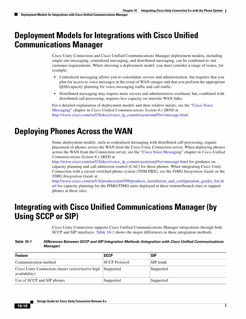
Cisco Unity Connection supports Cisco Unified Communications Manager integrations through both SCCP and SIP interfaces. Table 10-1 shows the major differences in these integration methods.
Table 10-1 Differences Between SCCP and SIP Integration Methods (Integration with Cisco Unified Communications
Manager)
Feature SCCP SIP
Communication method SCCP Protocol SIP trunk
Cisco Unity Connection cluster (active/active high availability)
Supported Supported
Use of SCCP and SIP phones Supported Supported
10-10Design Guide for Cisco Unity Connection Release 9.x
Chapter 10 Integrating Cisco Unity Connection 9.x with the Phone SystemIntegrating with Cisco Unified Communications Manager (by Using SCCP or SIP)
Cisco Unified Communications Manager Session Manager Edition 8.5 is supported with Cisco Unity Connection 9.x. Cisco Unified Communications Manager-Session Manager Edition (Cisco UCM-SME) Release 8.5 uses SIP Early Offer with SIP trunk Normalization script to integrate with Third-party PBX's. For more information, see the interoperability portal for Third-party PBX's tested with Unity Connection via a SIP trunk using CUCM-SME and SIP normalization at
http://www.cisco.com/en/US/solutions/ns340/ns414/ns728/interOp_ucSessionMgr.html.
For information on the compatibility of Connection and Cisco Unified CM versions, see the following documents:
• SCCP Compatibility Matrix: Cisco Unity Connection, Cisco Unified Communications Manager, and Cisco Unified Communications Manager Express at http://www.cisco.com/en/US/docs/voice_ip_comm/connection/compatibility/matrix/cucsccpmtx.html.
• SIP Trunk Compatibility Matrix: Cisco Unity Connection, Cisco Unified Communications Manager, and Cisco Unified Communications Manager Express at http://www.cisco.com/en/US/docs/voice_ip_comm/connection/compatibility/matrix/cucsiptrunkmtx.html.
For information on how to integrate Connection with Cisco Unified CM, see the applicable Cisco Unity Connection integration guide at http://www.cisco.com/en/US/products/ps6509/products_installation_and_configuration_guides_list.html.
For more information on using the SIP protocol to integrate Connection with Cisco Unified CM, see the “Integrating by Using SIP” section on page 10-25.
For information on the voice messaging solutions available for Cisco Unified CM, see the “Cisco Voice Messaging” chapter in Cisco Unified Communications System 9.x SRND at http://www.cisco.com/en/US/docs/voice_ip_comm/cucm/srnd/9x/vmessage.html.
See the following sections:
• Cisco Unified Communications Manager Authentication and Encryption for Cisco Unity Connection Voice Messaging Ports, page 10-12
• Port Group Configuration for Cisco Unified Communications Manager Cluster Failover, page 10-17
• Internet Protocol Version 6 (IPv6) Support with Cisco Unified Communications Manager Integrations, page 10-18
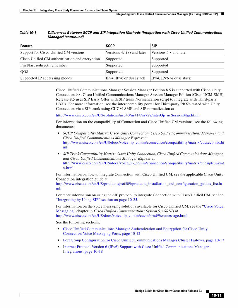
Support for Cisco Unified CM versions Versions 4.1(x) and later Versions 5.x and later
Cisco Unified CM authentication and encryption Supported Supported
First/last redirecting number Supported Supported
QOS Supported Supported
Supported IP addressing modes IPv4, IPv6 or dual stack IPv4, IPv6 or dual stack
Table 10-1 Differences Between SCCP and SIP Integration Methods (Integration with Cisco Unified Communications
Manager) (continued)
Feature SCCP SIP
10-11Design Guide for Cisco Unity Connection Release 9.x
Chapter 10 Integrating Cisco Unity Connection 9.x with the Phone SystemIntegrating with Cisco Unified Communications Manager (by Using SCCP or SIP)
Cisco Unified Communications Manager Authentication and Encryption for Cisco Unity Connection Voice Messaging Ports
A potential point of vulnerability for a Cisco Unity Connection system is the connection between Connection and Cisco Unified Communications Manager. Possible threats include:
• Man-in-the-middle attacks, in which an attacker intercepts and changes the data flowing between Cisco Unified CM and Connection voice messaging ports.
• Network traffic sniffing, in which an attacker captures phone conversations and signaling information that flow between Cisco Unified CM, the Connection voice messaging ports, and IP phones that are managed by Cisco Unified CM.
• Changing the call signaling between the Connection voice messaging ports and Cisco Unified CM.
• Changing the media stream between Connection voice messaging ports and endpoints, for example, phones or gateways.
• Identity theft of the Connection voice messaging port, in which a non-Connection device presents itself to Cisco Unified CM as a Connection voice messaging port.
• Identity theft of the Cisco Unified CM server, in which a non-Cisco Unified CM server presents itself to Connection voice messaging ports as a Cisco Unified CM server.
See the following sections for additional details:
• Cisco Unified Communications Manager Security Features, page 10-12
• When Data Is Encrypted, page 10-15
• Cisco Unified Communications Manager Cluster Security Mode Settings in Cisco Unity Connection, page 10-15
• Disabling and Reenabling Security, page 10-16
• Multiple Clusters Can Have Different Security Mode Settings, page 10-16
• Settings for Individual Voice Messaging Ports, page 10-16
• Packetization, page 10-17
Cisco Unified Communications Manager Security Features
Cisco Unified Communications Manager Release 4.1(3) or later for SCCP integrations or Cisco Unified Communications Manager Release 5.x or later for SIP trunk integrations can secure the connection with Cisco Unity Connection against security threats. The Cisco Unified CM security features that Connection can take advantage of are described in Table 10-2.
10-12Design Guide for Cisco Unity Connection Release 9.x

Chapter 10 Integrating Cisco Unity Connection 9.x with the Phone SystemIntegrating with Cisco Unified Communications Manager (by Using SCCP or SIP)
Table 10-2 Cisco Unified Communications Manager Security Features That Are Used by Cisco Unity Connection
Security Feature Description
Signaling authentication Uses the Transport Layer Security (TLS) protocol to validate that no tampering has occurred to signaling packets during transmission. Signaling authentication relies on the creation of the Cisco Certificate Trust List (CTL) file.
This feature protects against:
• Man-in-the-middle attacks that modify the information flow between Cisco Unified CM and the Connection voice messaging ports.
• Modification of the call signaling.
• Identity theft of the Connection voice messaging port.
• Identity theft of the Cisco Unified CM server.
Device authentication Validates the identity of the device. This process occurs between Cisco Unified CM and the Connection voice messaging ports when each device accepts the certificate of the other device. When the certificates are accepted, a secure connection between the devices is established. Device authentication relies on the creation of the Cisco Certificate Trust List (CTL) file.
This feature protects against:
• Man-in-the-middle attacks that modify the information flow between Cisco Unified CM and the Connection voice messaging ports.
• Modification of the media stream.
• Identity theft of the Connection voice messaging port.
• Identity theft of the Cisco Unified CM server.
Signaling encryption Uses cryptographic methods to protect (through encryption) the confidentiality of all SCCP and SIP signaling messages that are sent between the Connection voice messaging ports and Cisco Unified CM. Signaling encryption ensures that the information that pertains to the parties, DTMF digits that are entered by the parties, call status, media encryption keys, and so on are protected against unintended or unauthorized access.
This feature protects against:
• Man-in-the-middle attacks that observe the information flow between Cisco Unified CM and the Connection voice messaging ports.
• Network traffic sniffing that observes the signaling information flow between Cisco Unified CM and the Connection voice messaging ports.
10-13Design Guide for Cisco Unity Connection Release 9.x
Chapter 10 Integrating Cisco Unity Connection 9.x with the Phone SystemIntegrating with Cisco Unified Communications Manager (by Using SCCP or SIP)
Note that Cisco Unified CM authentication and encryption protects only calls to Connection. Messages that are recorded on Connection are not protected by Cisco Unified CM authentication and encryption but can be protected by the Connection secure messaging feature.
For more information on secure messaging, see the “Securing User Messages in Cisco Unity Connection 9.x” chapter of the Security Guide for Cisco Unity Connection Release 9.x, at http://www.cisco.com/en/US/docs/voice_ip_comm/connection/9x/security/guide/9xcucsecx.html.
The security features (authentication and encryption) between Connection and Cisco Unified CM require the following for SCCP integrations:
• A Cisco Unified CM CTL file that lists all Cisco Unified CM servers that are entered in Cisco Unity Connection Administration for secure clusters.
• A Connection server root certificate for each Connection server that uses authentication and/or encryption. A root certificate is valid for 7 years from the time it was created.
• Connection voice messaging port or port group device certificates that are rooted in the Connection server root certificate, and voice messaging ports or port groups that are present when registering with the Cisco Unified CM server.
The process of authentication and encryption of Connection voice messaging SCCP ports occurs as follows:
1. Each Connection voice messaging port connects to the TFTP server, via TFTP port 69, downloads the CTL file, and extracts the certificates for all Cisco Unified CM servers.
2. Each Connection voice messaging port establishes a network connection to the Cisco Unified CM TLS port. By default, the TLS port is 2443, though the port number is configurable.
3. Each Connection voice messaging port establishes a TLS connection to the Cisco Unified CM server, at which time the device certificate is verified and the voice messaging port is authenticated.
4. Each Connection voice messaging port registers with the Cisco Unified CM server, specifying whether the voice messaging port will also use media encryption.
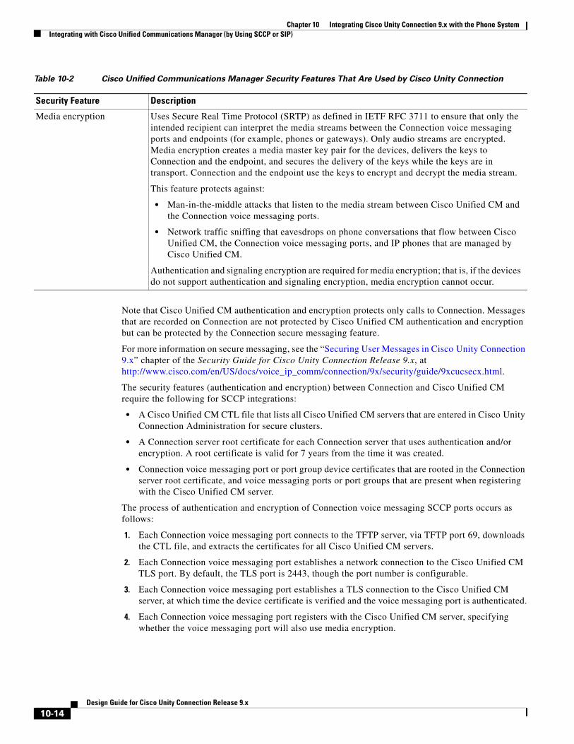
Media encryption Uses Secure Real Time Protocol (SRTP) as defined in IETF RFC 3711 to ensure that only the intended recipient can interpret the media streams between the Connection voice messaging ports and endpoints (for example, phones or gateways). Only audio streams are encrypted. Media encryption creates a media master key pair for the devices, delivers the keys to Connection and the endpoint, and secures the delivery of the keys while the keys are in transport. Connection and the endpoint use the keys to encrypt and decrypt the media stream.
This feature protects against:
• Man-in-the-middle attacks that listen to the media stream between Cisco Unified CM and the Connection voice messaging ports.
• Network traffic sniffing that eavesdrops on phone conversations that flow between Cisco Unified CM, the Connection voice messaging ports, and IP phones that are managed by Cisco Unified CM.
Authentication and signaling encryption are required for media encryption; that is, if the devices do not support authentication and signaling encryption, media encryption cannot occur.
Table 10-2 Cisco Unified Communications Manager Security Features That Are Used by Cisco Unity Connection
Security Feature Description
10-14Design Guide for Cisco Unity Connection Release 9.x
Chapter 10 Integrating Cisco Unity Connection 9.x with the Phone SystemIntegrating with Cisco Unified Communications Manager (by Using SCCP or SIP)
The process of authentication and encryption of Connection voice messaging SIP port groups occurs as follows:
1. Each Connection voice messaging port group connects to the TFTP server, via TFTP port 69, downloads the CTL file, and extracts the certificates for all Cisco Unified CM servers.
2. Each Connection voice messaging port group establishes a network connection to the Cisco Unified CM TLS port. By default, the TLS port is 2443, though the port number is configurable.
3. Each Connection voice messaging port group establishes a TLS connection to the Cisco Unified CM server, at which time the device certificate is verified and the voice messaging port group is authenticated.
4. Each Connection voice messaging port group registers with the Cisco Unified CM server, specifying whether the voice messaging port group will also use media encryption.
When Data Is Encrypted
When a call is made between Cisco Unity Connection and Cisco Unified CM, the call-signaling messages and the media stream are handled in the following manner:
• If both endpoints are set for encrypted mode, the call-signaling messages and the media stream are encrypted.
• If one endpoint is set for authenticated mode and the other endpoint is set for encrypted mode, the call-signaling messages are authenticated. But neither the call-signaling messages nor the media stream are encrypted.
• If one endpoint is set for non-secure mode and the other endpoint is set for encrypted mode, neither the call-signaling messages nor the media stream are encrypted.
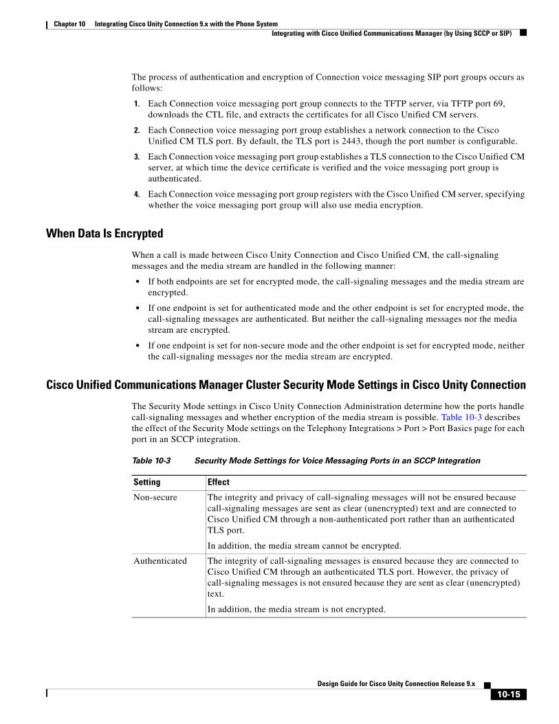
Cisco Unified Communications Manager Cluster Security Mode Settings in Cisco Unity Connection
The Security Mode settings in Cisco Unity Connection Administration determine how the ports handle call-signaling messages and whether encryption of the media stream is possible. Table 10-3 describes the effect of the Security Mode settings on the Telephony Integrations > Port > Port Basics page for each port in an SCCP integration.
Table 10-3 Security Mode Settings for Voice Messaging Ports in an SCCP Integration
Setting Effect
Non-secure The integrity and privacy of call-signaling messages will not be ensured because call-signaling messages are sent as clear (unencrypted) text and are connected to Cisco Unified CM through a non-authenticated port rather than an authenticated TLS port.
In addition, the media stream cannot be encrypted.
Authenticated The integrity of call-signaling messages is ensured because they are connected to Cisco Unified CM through an authenticated TLS port. However, the privacy of call-signaling messages is not ensured because they are sent as clear (unencrypted) text.
In addition, the media stream is not encrypted.
10-15Design Guide for Cisco Unity Connection Release 9.x
Chapter 10 Integrating Cisco Unity Connection 9.x with the Phone SystemIntegrating with Cisco Unified Communications Manager (by Using SCCP or SIP)
Disabling and Reenabling Security
The authentication and encryption features between Cisco Unity Connection and Cisco Unified CM can be enabled and disabled by changing the Security Mode for all Cisco Unified CM clusters to Non-Secure, and by changing the applicable settings in the Cisco Unified Communications Manager Administration.
Authentication and encryption can be reenabled by changing the Security Mode to Authenticated or Encrypted.
Note After disabling or re-enabling authentication and encryption, it is not necessary to export the Connection server root certificate and copy it to all Cisco Unified CM servers.
Multiple Clusters Can Have Different Security Mode Settings
When Cisco Unity Connection has multiple Cisco Unified CM phone system integrations, each Cisco Unified CM phone system integration can have different Security Mode settings. For example, one Cisco Unified CM phone system integration can be set to Encrypted, and a second Cisco Unified CM phone system integration can be set to Non-Secure.
Settings for Individual Voice Messaging Ports
For troubleshooting purposes, authentication and encryption for Cisco Unity Connection voice messaging ports can be individually enabled and disabled. At all other times, we recommend that the Security Mode setting for all individual voice messaging ports in a Cisco Unified CM port group be the same.
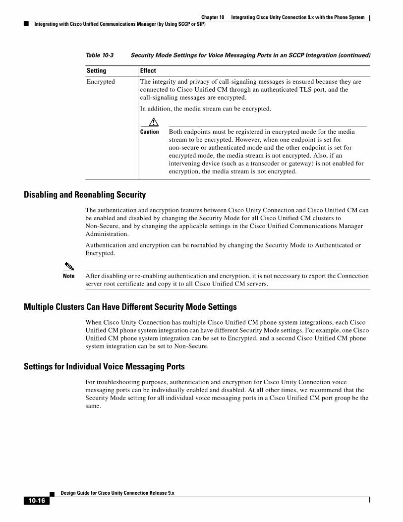
Encrypted The integrity and privacy of call-signaling messages is ensured because they are connected to Cisco Unified CM through an authenticated TLS port, and the call-signaling messages are encrypted.
In addition, the media stream can be encrypted.
Caution Both endpoints must be registered in encrypted mode for the media stream to be encrypted. However, when one endpoint is set for non-secure or authenticated mode and the other endpoint is set for encrypted mode, the media stream is not encrypted. Also, if an intervening device (such as a transcoder or gateway) is not enabled for encryption, the media stream is not encrypted.
Table 10-3 Security Mode Settings for Voice Messaging Ports in an SCCP Integration (continued)
Setting Effect
10-16Design Guide for Cisco Unity Connection Release 9.x
Chapter 10 Integrating Cisco Unity Connection 9.x with the Phone SystemIntegrating with Cisco Unified Communications Manager (by Using SCCP or SIP)
Packetization
The Real-Time Transport Protocol (RTP) is used to send and receive audio packets over the IP network. Each discrete packet has a fixed-size header, but the packets themselves can vary in size, depending on the size of the audio stream to be transported (which varies by codec) and the packetization setting. This variable size function helps utilize network bandwidth more efficiently. Reducing the number of packets that are created per call sends fewer total bytes over the network.
Packetization is set in the Cisco Unified CM Service Parameters, in the Preferred G711 Millisecond PacketSize and Preferred G729 Millisecond PacketSize parameters. Cisco Unity Connection supports any packet size up to 30ms for G.711 audio, and any packet size up to 60 ms for G.729a audio. The default setting is 20ms for both; there may be latency issues with lower settings.
DSCP is a priority setting on each packet. DSCP helps intermediary routers manage network congestion and lets them know which packets to prioritize ahead of others. Following Cisco AVVID standards, Connection marks the SCCP and SIP packets (call control) with a default DSCP value of 24 (the TOS octet is 0x60), and the RTP packets (audio traffic) with a default DSCP value of 46 (the TOS octet is 0xB8). Thus, the RTP audio packets can be assigned priority over other packets by using the router settings. Note that even though Cisco Unified CM allows you set different DSCP values, when integrated with Connection, the DSCP values set by Connection always take precedence. The marking of both SCCP and SIP packets is configurable in Connection on the System Settings > Advanced > Telephony Configuration page in Cisco Unity Connection Administration.
With each new audio stream (once per call), Cisco Unified CM tells Connection which packet size to use, and Connection sets the DSCP priority for the stream. The entire stream (call) stays at the specified packet size and priority. For example, an audio stream could be broken up into packets of 30ms each. A 30ms G.729a audio stream would be 30 bytes plus the header per packet, and a 30ms G.711 stream would be 240 bytes plus the header per packet. For information on setting Cisco Unified CM Service Parameters, see the Cisco Unified CM documentation at http://www.cisco.com/en/US/products/sw/voicesw/ps556/tsd_products_support_series_home.html.
Note You can change the codecs that Connection advertises on the Telephony Integrations > Port Group > Edit Codec Advertising configuration page in Cisco Unity Connection Administration.
For a discussion of supported advertised or “on the line” audio codecs and system-level recording audio codecs, see the “Audio Codecs” section on page 3-1.
Port Group Configuration for Cisco Unified Communications Manager Cluster Failover
For Cisco Unified Communications Manager SCCP integrations, when a Cisco Unified CM cluster is configured and Cisco Unified CM failover occurs as calls are in progress, the voice messaging ports may experience a delay registering with the secondary Cisco Unified CM server.
Cisco Unity Connection ports can register more quickly after Cisco Unified CM failover occurs if the port groups are configured as follows:
• You create two port groups for the SCCP integration:
– The first port group contains half the voice messaging ports for the Cisco Unified CM integration (including answering and dialout ports) configured as described in the applicable chapter of the Cisco Unified Communications Manager SCCP Integration Guide for Cisco Unity Connection Release 9.x.
10-17Design Guide for Cisco Unity Connection Release 9.x
Chapter 10 Integrating Cisco Unity Connection 9.x with the Phone SystemIntegrating with Cisco Unified Communications Manager (by Using SCCP or SIP)
– The second port group contains the remaining half of the ports for the Cisco Unified CM integration (including answering and dialout ports) as described in the applicable chapter of the same guide.
Note The Cisco Unified Communications Manager SCCP Integration Guide for Cisco Unity Connection Release 9.x. is available at http://www.cisco.com/en/US/docs/voice_ip_comm/connection/9x/integration/guide/cucm_sccp/cucintcucmskinny.html.
• On the Telephony Integrations > Port Group > Port Group Basics > Edit Servers page, you list the Cisco Unified CM servers in different orders:
– For the first port group, the Cisco Unified CM servers are listed in the order specified in the applicable chapter of the Cisco Unified Communications Manager SCCP Integration Guide for Cisco Unity Connection Release 9.x.
– For the second port group, the Cisco Unified CM servers are listed in the reverse order.
Internet Protocol Version 6 (IPv6) Support with Cisco Unified Communications Manager Integrations
Cisco Unity Connection supports IPv4, IPv6, or dual-stack (IPv4 and IPv6) addressing with Cisco Unified Communications Manager phone system integrations via SCCP or SIP. When IPv6 is enabled, Connection can obtain an IPv6 address either through router advertisement, through DHCP, or by manually configuring an address either in Cisco Unified Operating System Administration or by using the command-line interface.
For SCCP integrations with Cisco Unified CM, if Connection is configured to listen for incoming IPv4 and IPv6 traffic, you can configure the addressing mode that Connection uses for call control signaling for each port group to use either IPv4 or IPv6. (This mode is also used when connecting to a TFTP server.)
For SIP integrations with Cisco Unified CM, if Connection is configured to listen for incoming IPv4 and IPv6 traffic, you can configure the addressing mode that Connection uses for call control signaling for each port group to use either IPv4 or IPv6. (This mode is also used when connecting to a TFTP server.) In addition, you can configure the addressing mode that Connection uses for media for each port group to use either IPv4 or IPv6.
IPv6 support is disabled by default. You can enable IPv6 and configure IPv6 address settings either in Cisco Unified Operating System Administration or in the CLI. For information on enabling and configuring IPv6 when setting up a new Cisco Unified CM integration, see the applicable Cisco Unity Connection integration guide at http://www.cisco.com/en/US/products/ps6509/products_installation_and_configuration_guides_list.html. For information on enabling and configuring IPv6 for an existing Cisco Unified CM integration, see the “Adding or Changing the IPv6 Addresses of Cisco Unity Connection 9.x Servers” chapter of the Reconfiguration and Upgrade Guide for Cisco Unity Connection Release 9.x at http://www.cisco.com/en/US/docs/voice_ip_comm/connection/9x/upgrade/guide/9xcucrugx.html.
Note the following considerations when deploying IPv6 for Cisco Unified CM integrations:
• The CTL file required for security features (authentication and encryption) between Connection and Cisco Unified CM for SCCP integrations uses IPv4 addressing. Therefore, in order to use authentication and/or encryption with SCCP, you must use either IPv4 or dual-stack addressing.
10-18Design Guide for Cisco Unity Connection Release 9.x
Chapter 10 Integrating Cisco Unity Connection 9.x with the Phone SystemIntegrating with Cisco Unified Communications Manager Express (by Using SCCP or SIP)
• Some versions of Cisco Adaptive Security Appliance (ASA) do not support application inspection for IPv6 traffic for Unified Communications application servers and endpoints. Cisco recommends not using IPv6 for Unified Communications if you are using a Cisco ASA version that does not provide this support. See the documentation for your version of Cisco ASA to determine whether application inspection is supported in your deployment.
Integrating with Cisco Unified Communications Manager Express (by Using SCCP or SIP)
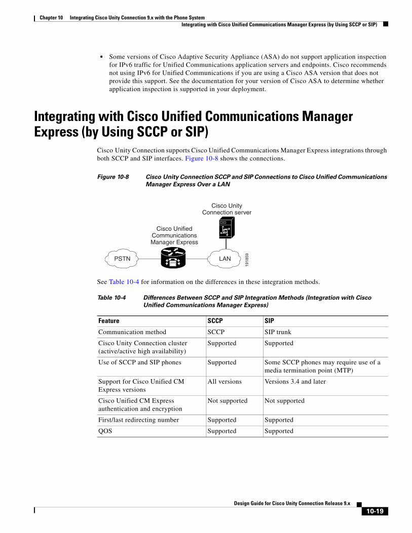
Cisco Unity Connection supports Cisco Unified Communications Manager Express integrations through both SCCP and SIP interfaces. Figure 10-8 shows the connections.
Figure 10-8 Cisco Unity Connection SCCP and SIP Connections to Cisco Unified Communications
Manager Express Over a LAN
See Table 10-4 for information on the differences in these integration methods.
Cisco UnifiedCommunicationsManager Express
LANPSTN
1918
59
Cisco UnityConnection server
C
Table 10-4 Differences Between SCCP and SIP Integration Methods (Integration with Cisco
Unified Communications Manager Express)
Feature SCCP SIP
Communication method SCCP SIP trunk
Cisco Unity Connection cluster (active/active high availability)
Supported Supported
Use of SCCP and SIP phones Supported Some SCCP phones may require use of a media termination point (MTP)
Support for Cisco Unified CM Express versions
All versions Versions 3.4 and later
Cisco Unified CM Express authentication and encryption
Not supported Not supported
First/last redirecting number Supported Supported
QOS Supported Supported
10-19Design Guide for Cisco Unity Connection Release 9.x
Chapter 10 Integrating Cisco Unity Connection 9.x with the Phone SystemIntegrating with Cisco Unified Communications Manager Express (by Using SCCP or SIP)
For information on the compatibility of Connection and Cisco Unified Communications Manager Express versions, see the following:
• SCCP Compatibility Matrix: Cisco Unity Connection, Cisco Unified Communications Manager, and Cisco Unified Communications Manager Express at http://www.cisco.com/en/US/docs/voice_ip_comm/connection/compatibility/matrix/cucsccpmtx.html.
• SIP Trunk Compatibility Matrix: Cisco Unity Connection, Cisco Unified Communications Manager, and Cisco Unified Communications Manager Express at http://www.cisco.com/en/US/docs/voice_ip_comm/connection/compatibility/matrix/cucsiptrunkmtx.html.
For information on how to integrate Connection with Cisco Unified CM Express, see the applicable Cisco Unity Connection integration guide at http://www.cisco.com/en/US/products/ps6509/products_installation_and_configuration_guides_list.html.
For more information on using the SIP protocol to integrate Connection with Cisco Unified CM Express, see the “Integrating by Using SIP” section on page 10-25.
Multiple Cisco Unified Communications Manager Express Version SupportA single Cisco Unity Connection server can support multiple versions of Cisco Unified CM Express. The version of Connection being used must support all versions of Cisco Unified CM Express. See the following documents:
• SCCP Compatibility Matrix: Cisco Unity Connection, Cisco Unified Communications Manager, and Cisco Unified Communications Manager Express at http://www.cisco.com/en/US/docs/voice_ip_comm/connection/compatibility/matrix/cucsccpmtx.html.
• SIP Trunk Compatibility Matrix: Cisco Unity Connection, Cisco Unified Communications Manager, and Cisco Unified Communications Manager Express at http://www.cisco.com/en/US/docs/voice_ip_comm/connection/compatibility/matrix/cucsiptrunkmtx.html.
Multiple Cisco Unified Communications Manager Express Routers Integrating with a Single Cisco Unity Connection Server
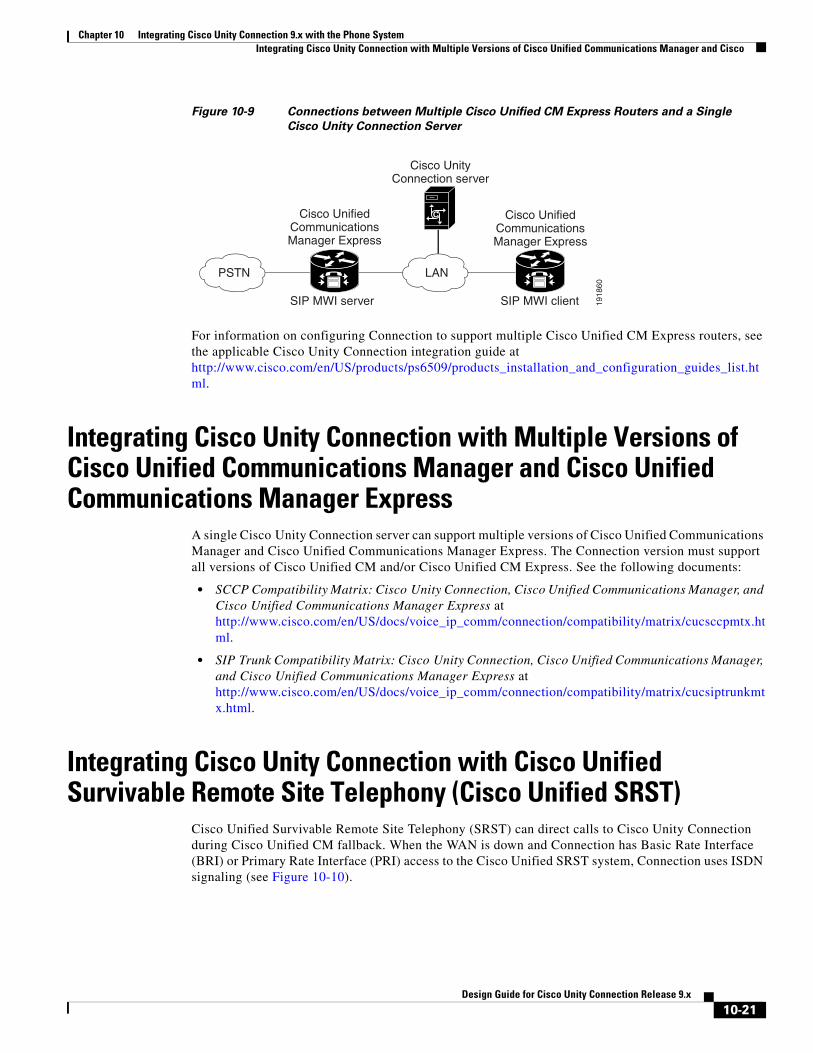
A single, centralized Cisco Unity Connection server can be used by multiple Cisco Unified CM Express routers. This configuration requires that one Cisco Unified CM Express router be on the same LAN as the Connection server, and that this Cisco Unified CM Express router register all Connection voice messaging ports. This Cisco Unified CM Express router (the SIP MWI server) is a proxy server that relays SIP MWI messages between the Connection server and all other Cisco Unified CM Express routers (the SIP MWI clients). Note that Connection voice messaging ports register only with the SIP MWI server (the Cisco Unified CM Express router that is on the same LAN as the Connection server), not with the SIP MWI clients. See Figure 10-9.
10-20Design Guide for Cisco Unity Connection Release 9.x
Chapter 10 Integrating Cisco Unity Connection 9.x with the Phone SystemIntegrating Cisco Unity Connection with Multiple Versions of Cisco Unified Communications Manager and Cisco
Figure 10-9 Connections between Multiple Cisco Unified CM Express Routers and a Single
Cisco Unity Connection Server
For information on configuring Connection to support multiple Cisco Unified CM Express routers, see the applicable Cisco Unity Connection integration guide at http://www.cisco.com/en/US/products/ps6509/products_installation_and_configuration_guides_list.html.
Integrating Cisco Unity Connection with Multiple Versions of Cisco Unified Communications Manager and Cisco Unified Communications Manager Express
A single Cisco Unity Connection server can support multiple versions of Cisco Unified Communications Manager and Cisco Unified Communications Manager Express. The Connection version must support all versions of Cisco Unified CM and/or Cisco Unified CM Express. See the following documents:
• SCCP Compatibility Matrix: Cisco Unity Connection, Cisco Unified Communications Manager, and Cisco Unified Communications Manager Express at http://www.cisco.com/en/US/docs/voice_ip_comm/connection/compatibility/matrix/cucsccpmtx.html.
• SIP Trunk Compatibility Matrix: Cisco Unity Connection, Cisco Unified Communications Manager, and Cisco Unified Communications Manager Express at http://www.cisco.com/en/US/docs/voice_ip_comm/connection/compatibility/matrix/cucsiptrunkmtx.html.
Integrating Cisco Unity Connection with Cisco Unified Survivable Remote Site Telephony (Cisco Unified SRST)
Cisco Unified Survivable Remote Site Telephony (SRST) can direct calls to Cisco Unity Connection during Cisco Unified CM fallback. When the WAN is down and Connection has Basic Rate Interface (BRI) or Primary Rate Interface (PRI) access to the Cisco Unified SRST system, Connection uses ISDN signaling (see Figure 10-10).
Cisco UnifiedCommunicationsManager Express
LANPSTN
1918
60
Cisco UnifiedCommunicationsManager Express
SIP MWI server SIP MWI client
Cisco UnityConnection server
C
10-21Design Guide for Cisco Unity Connection Release 9.x
Chapter 10 Integrating Cisco Unity Connection 9.x with the Phone SystemIntegrating Cisco Unity Connection with Cisco Unified Survivable Remote Site Telephony (Cisco Unified SRST)
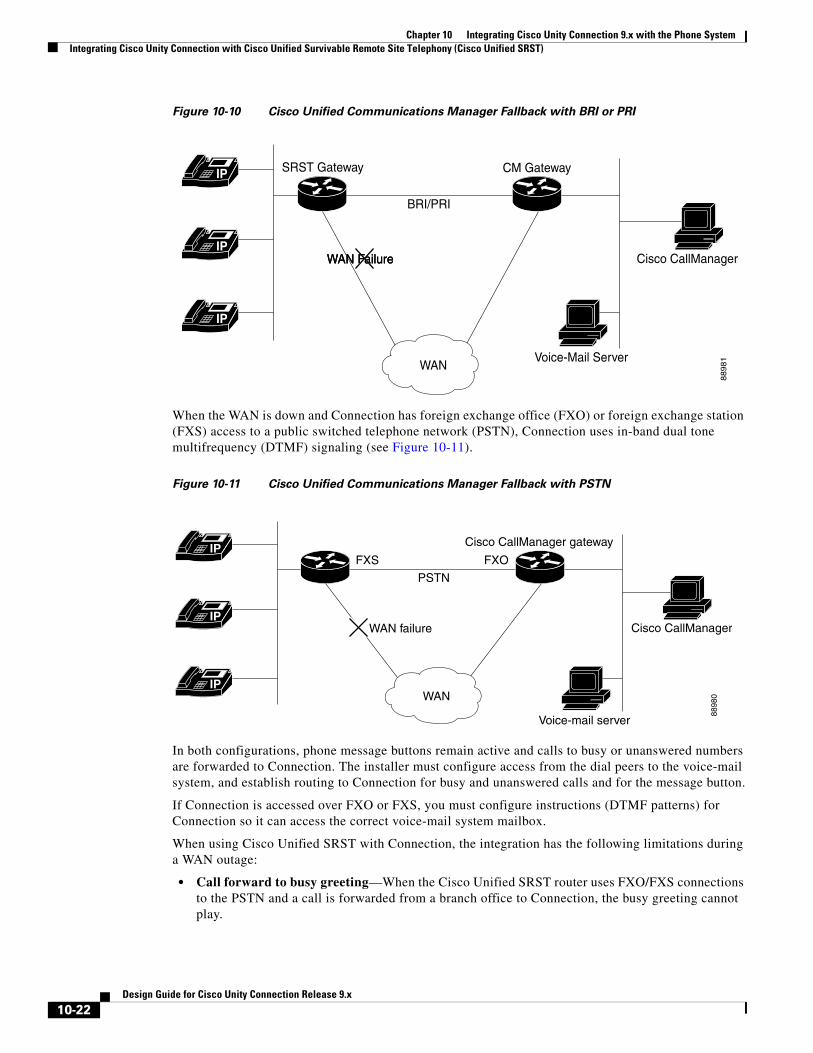
Figure 10-10 Cisco Unified Communications Manager Fallback with BRI or PRI
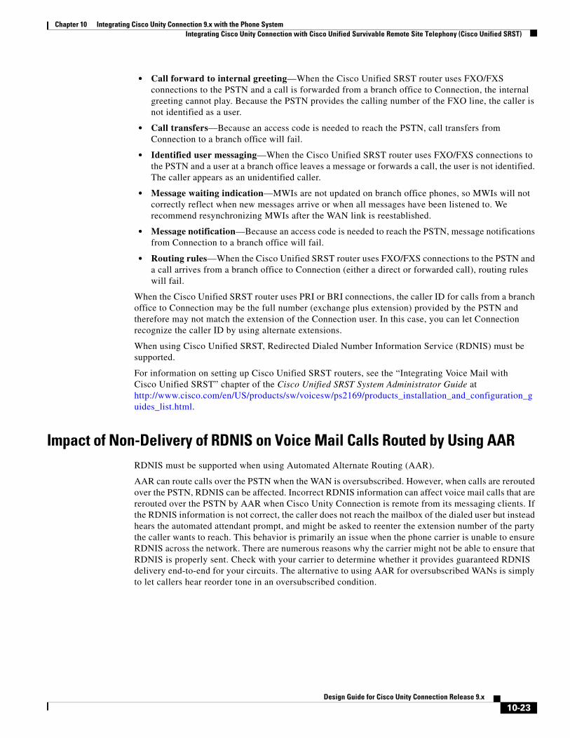
When the WAN is down and Connection has foreign exchange office (FXO) or foreign exchange station (FXS) access to a public switched telephone network (PSTN), Connection uses in-band dual tone multifrequency (DTMF) signaling (see Figure 10-11).
Figure 10-11 Cisco Unified Communications Manager Fallback with PSTN
In both configurations, phone message buttons remain active and calls to busy or unanswered numbers are forwarded to Connection. The installer must configure access from the dial peers to the voice-mail system, and establish routing to Connection for busy and unanswered calls and for the message button.
If Connection is accessed over FXO or FXS, you must configure instructions (DTMF patterns) for Connection so it can access the correct voice-mail system mailbox.
When using Cisco Unified SRST with Connection, the integration has the following limitations during a WAN outage:
• Call forward to busy greeting—When the Cisco Unified SRST router uses FXO/FXS connections to the PSTN and a call is forwarded from a branch office to Connection, the busy greeting cannot play.
IP
IP
IP
88
98
1
Cisco CallManager
Voice-Mail Server
CM Gateway
BRI/PRI
SRST Gateway
WAN
WAN FailureWAN FailureWAN Failure
IP
IP
IP
8898
0
Cisco CallManager
Voice-mail server
Cisco CallManager gateway
FXS
PSTN
FXO
WAN
WAN failure
10-22Design Guide for Cisco Unity Connection Release 9.x
Chapter 10 Integrating Cisco Unity Connection 9.x with the Phone SystemIntegrating Cisco Unity Connection with Cisco Unified Survivable Remote Site Telephony (Cisco Unified SRST)
• Call forward to internal greeting—When the Cisco Unified SRST router uses FXO/FXS connections to the PSTN and a call is forwarded from a branch office to Connection, the internal greeting cannot play. Because the PSTN provides the calling number of the FXO line, the caller is not identified as a user.
• Call transfers—Because an access code is needed to reach the PSTN, call transfers from Connection to a branch office will fail.
• Identified user messaging—When the Cisco Unified SRST router uses FXO/FXS connections to the PSTN and a user at a branch office leaves a message or forwards a call, the user is not identified. The caller appears as an unidentified caller.
• Message waiting indication—MWIs are not updated on branch office phones, so MWIs will not correctly reflect when new messages arrive or when all messages have been listened to. We recommend resynchronizing MWIs after the WAN link is reestablished.
• Message notification—Because an access code is needed to reach the PSTN, message notifications from Connection to a branch office will fail.
• Routing rules—When the Cisco Unified SRST router uses FXO/FXS connections to the PSTN and a call arrives from a branch office to Connection (either a direct or forwarded call), routing rules will fail.
When the Cisco Unified SRST router uses PRI or BRI connections, the caller ID for calls from a branch office to Connection may be the full number (exchange plus extension) provided by the PSTN and therefore may not match the extension of the Connection user. In this case, you can let Connection recognize the caller ID by using alternate extensions.
When using Cisco Unified SRST, Redirected Dialed Number Information Service (RDNIS) must be supported.
For information on setting up Cisco Unified SRST routers, see the “Integrating Voice Mail with Cisco Unified SRST” chapter of the Cisco Unified SRST System Administrator Guide at http://www.cisco.com/en/US/products/sw/voicesw/ps2169/products_installation_and_configuration_guides_list.html.
Impact of Non-Delivery of RDNIS on Voice Mail Calls Routed by Using AARRDNIS must be supported when using Automated Alternate Routing (AAR).
AAR can route calls over the PSTN when the WAN is oversubscribed. However, when calls are rerouted over the PSTN, RDNIS can be affected. Incorrect RDNIS information can affect voice mail calls that are rerouted over the PSTN by AAR when Cisco Unity Connection is remote from its messaging clients. If the RDNIS information is not correct, the caller does not reach the mailbox of the dialed user but instead hears the automated attendant prompt, and might be asked to reenter the extension number of the party the caller wants to reach. This behavior is primarily an issue when the phone carrier is unable to ensure RDNIS across the network. There are numerous reasons why the carrier might not be able to ensure that RDNIS is properly sent. Check with your carrier to determine whether it provides guaranteed RDNIS delivery end-to-end for your circuits. The alternative to using AAR for oversubscribed WANs is simply to let callers hear reorder tone in an oversubscribed condition.
10-23Design Guide for Cisco Unity Connection Release 9.x
Chapter 10 Integrating Cisco Unity Connection 9.x with the Phone SystemSurvivable Remote Site Voicemail
Integrating Cisco Unity Connection with Cisco Unified Communications Manager Express in SRST Mode
Cisco Unity Connection supports a topology with centralized call processing and distributed messaging, in which your Connection server is located at a remote site or branch office and registered with Cisco Unified CM at a central site.
When the WAN link fails, the phones fall back to the Cisco Unified CM Express-as-SRST device. Connection can also fall back to the Cisco Unified CM Express-as-SRST device, which lets users at the remote site access their voice messages and see message waiting indicators (MWIs) during a WAN outage. Note that MWIs must be resynchronized from the Connection server whenever a failover happens from Cisco Unified CM to Cisco Unified CM Express-as-SRST or vice versa.
For information on setting up this configuration, see the Integrating Cisco Unity Connection with Cisco Unified CME-as-SRST configuration guide at http://www.cisco.com/en/US/products/sw/voicesw/ps4625/products_installation_and_configuration_guides_list.html.
Survivable Remote Site VoicemailRevised December 03, 2012
Cisco Unity Connection Survivable Remote Site Voicemail (Connection SRSV) is a backup voicemail solution that works in conjunction with Cisco Unified Survivable Remote Site Telephony (SRST) for providing voicemail service to a branch during WAN outages.
Connection SRSV is used in the centralized Cisco Unified Communications Manager and Cisco Unity Connection environment with multiple branch offices or small sites. It provides limited voicemail and auto-attendant features that remain in synchronization with the central Connection voicemail service so that when the WAN outage or failure occurs, the Connection SRSV solution can provide voicemail service to the subscribers at the branch. However, as soon as the network is restored, all the voicemails received by the branch subscribers are automatically uploaded to the central Connection voicemail server.
For more information on how to configure Cisco Unity Connection SRSV at central Connection location, refer to the "Managing Cisco Unity Connection Survivable Remote Site Voicemail in Cisco Unity Connection 9.1(1) and later" chapter of the System Administration Guide for Cisco Unity Connection available at http://www.cisco.com/en/US/docs/voice_ip_comm/connection/9x/administration/guide/9xcucsagx.html.
For additional information about SRSV, see the following documents:
• The “Survivable Remote Site Voicemail” section in the “Cisco Voice Messaging” chapter of the Cisco Unified Communications System 9.x SRND, at http://www.cisco.com/en/US/docs/voice_ip_comm/cucm/srnd/9x/vmessage.html.
• The Complete Reference Guide for Cisco Unity Connection Survivable Remote Site Voicemail (SRSV) data sheet at http://www.cisco.com/en/US/docs/voice_ip_comm/connection/9x/srsv/guide/9xcucsrsvx.html.
10-24Design Guide for Cisco Unity Connection Release 9.x
Chapter 10 Integrating Cisco Unity Connection 9.x with the Phone SystemIntegrating by Using SIP
Integrating by Using SIPSIP (Session Initiation Protocol) is the Internet Engineering Task Force standard for multimedia calls over IP. SIP is a peer-to-peer, ASCII-based protocol that uses requests and responses to establish, maintain, and terminate calls (or sessions) between two or more end points. See Table 10-5.
Cisco Unity Connection accepts calls from a proxy server. Connection relies on a proxy server or call agent to authenticate calls.
SIP uses a request/response method to establish communications between various components in the network and to ultimately establish a conference (call or session) between two or more endpoints. A single call may involve several clients and servers.
Users in a SIP network are identified by:
• A unique phone or extension number.
• A unique SIP address, which is similar to an email address and uses the format sip:<userID>@<domain>. The user ID can be either a user name or an E.164 address.
When a user initiates a call, a SIP request typically goes to a SIP server (either a proxy server or a redirect server). The request includes the caller address (From) and the address of the called party (To).
SIP messages are in text format using ISO 10646 in UTF-8 encoding (like HTML). In addition to the address information, a SIP message contains a start-line specifying the method and the protocol, a number of header fields specifying call properties and service information, and an optional message body which can contain a session description.
Table 10-5 SIP Network Components
Component Description
SIP proxy server An intermediate device that receives SIP requests from a client and then forwards the requests on behalf of the client. Proxy servers receive SIP messages and forward them to the next SIP server in the network. Proxy servers can provide functions such as authentication, authorization, network access control, routing, reliable request retransmission, and security.
Redirect server Provides information to the client about the next hop or hops that a message should take. The client then contacts the next hop server or user-agent server directly.
Registrar server Processes requests from user agent clients for registration of their current location. Registrar servers are often installed on the redirect or proxy server.
Phones Acts as either a server or client. Softphones (PCs that have phone capabilities installed) and Cisco SIP IP phones can initiate SIP requests and respond to requests.
Gateways Provide call control. Gateways provide many services; the most common is a translation function between SIP call endpoints and other terminal types. This function includes translation between transmission formats and between communications procedures. In addition, the gateway translates between audio and video codecs, and performs call setup and clearing on both the LAN side and the switched-circuit network side.
10-25Design Guide for Cisco Unity Connection Release 9.x
Chapter 10 Integrating Cisco Unity Connection 9.x with the Phone SystemIntegrating with Circuit-Switched Phone Systems by Using PIMG or TIMG Units
Supported SIP IntegrationsCisco Unity Connection supports the following SIP integrations:
• SIP trunks to supported versions of Cisco Unified Communications Manager and Cisco Unified Communications Manager Express. For a list of Cisco Unified CM and Cisco Unified CM Express versions supported as SIP trunks, see SIP Trunk Compatibility Matrix: Cisco Unity Connection, Cisco Unified Communications Manager, and Cisco Unified Communications Manager Express at http://www.cisco.com/en/US/docs/voice_ip_comm/connection/compatibility/matrix/cucsiptrunkmtx.html.
• Cisco SIP Proxy Server (CSPS).
• Cisco ISR voice gateways for integrating Connection to a QSIG-enabled phone system (see the “Integrating Cisco Unity Connection with a QSIG-Enabled Phone System by Using Cisco ISR Voice Gateways” section on page 10-31).
Third-party SIP trunks are currently not supported.
For more information on configuring SIP trunks between Connection and Cisco Unified CM or Cisco Unified CM Express, see the applicable SIP trunk integration guide at http://www.cisco.com/en/US/products/ps6509/products_installation_and_configuration_guides_list.html.
Note Cisco Unity Connection extracts Caller Id from Remote Party Id field and FROM field in SIP Invite. In addition, when the Remote Party Id option is unchecked on CUCM SIP trunk and the FROM field is set to Anonymous in a SIP header, Connection treats the caller as unknown.
Integrating with Circuit-Switched Phone Systems by Using PIMG or TIMG Units
Cisco Unity Connection can integrate with circuit-switched phone systems by using the PIMG or TIMG units (media gateways) between circuit-switched phone systems and IP networks.
For a list of circuit-switched phone systems supported with Connection by using PIMG and TIMG integrations, see the applicable Cisco Unity Connection integration guide at http://www.cisco.com/en/US/products/ps6509/products_installation_and_configuration_guides_list.html.
Description of PIMG IntegrationsThe PIMG integration uses one or more PIMG units between the circuit-switched phone systems and IP network. On the circuit-switched phone system side, there are both digital (feature-set) and analog interfaces; the interface used depends on the phone system to which Cisco Unity Connection is connected. On the IP side, there is a SIP interface, which is how Connection communicates with the PIMG units. To Connection, the integration is essentially a SIP integration. Connection communicates with the PIMG units over the IP network by using SIP and RTP protocols. The PIMG units communicate with the circuit-switched phone system over the phone network using phone system-specific protocols (digital, analog, or serial).
For high-level descriptions of each PIMG integration type, and illustrations showing the network connections, see the “How a Phone System Integration Works” section on page 10-2.
10-26Design Guide for Cisco Unity Connection Release 9.x
Chapter 10 Integrating Cisco Unity Connection 9.x with the Phone SystemIntegrating with Circuit-Switched Phone Systems by Using PIMG or TIMG Units
Setup and ConfigurationFor PIMG/TIMG setup and configuration, the installer does the following steps as documented in the applicable integration guide:
1. Configure the phone system.
2. Configure the PIMG/TIMG units. PIMG/TIMG settings are somewhat phone system-specific, but less so than phone system configuration.
3. Configure Cisco Unity Connection for the integration.
For information on configuring the phone system, PIMG/TIMG units, and Connection, see the applicable Cisco Unity Connection integration guide at http://www.cisco.com/en/US/products/ps6509/products_installation_and_configuration_guides_list.html.
Firmware UpdatesNote that when receiving shipment of PIMG or TIMG units, it may be necessary to update the firmware on the units. The PIMG/TIMG Administration interface provides a simple method to update the firmware files. Firmware updates are available at http://tools.cisco.com/support/downloads/go/Redirect.x?mdfid=278875240 (note that you must sign in to www.cisco.com to access the URL). For details, see the applicable integration guide.
Serial IntegrationsCisco Unity Connection supports the following serial protocols:
• SMDI
• MCI
• MD-110
The serial port on PIMG/TIMG units was originally designed as a management port rather than as a standard RS-232 serial port. Consequently, a custom serial cable (which is available from Cisco) is necessary for the data link between the phone system and the master PIMG/TIMG unit.
Increasing Port CapacityPIMG units have eight ports. To increase system port capacity, multiple PIMG units can be stacked. For example, if 32 ports are needed, four PIMG units can be stacked.
TIMG units, which integrate with circuit-switched phone systems that support T1-CAS, have 24 T1 ports per span in a single rack-optimized unit. Single-span, dual-span, and quad-span TIMG units are available.
10-27Design Guide for Cisco Unity Connection Release 9.x
Chapter 10 Integrating Cisco Unity Connection 9.x with the Phone SystemIntegrating with Circuit-Switched Phone Systems by Using PIMG or TIMG Units
Cisco Unity Connection ClustersPIMG/TIMG integrations support Cisco Unity Connection clusters (active/active high availability). Configuration changes are required both for the PIMG/TIMG units and for the Connection servers, as described in the applicable Cisco Unity Connection integration guide at http://www.cisco.com/en/US/products/ps6509/products_installation_and_configuration_guides_list.html.
Multiple Integration Support/Branch Office ConsolidationRevised August 6th, 2013PIMG/TIMG units can be separated by a WAN to support circuit-switched phone systems at remote branch office sites. For example, Cisco Unity Connection could be placed at a centralized headquarters and support circuit-switched phone systems both at the headquarters and at the branch office sites.
As an example, assuming there are four phone systems from four different manufacturers (for example, Nortel, Avaya, NEC, and Siemens), four different phone system integrations could be created on the Connection server to support the four phone systems. A standalone Connection server supports up to 250 ports that will connect to the four phone systems. For example:
• At the Seattle site, 19 PIMG units can be stacked to support 150 ports.
• At the New York site, four PIMG units can be stacked to support 30 ports.
• At the Tokyo site, seven PIMG unit can be used to support 50 ports.
• At the Dallas site, three PIMG unit can be used to support 20 ports.
Note that even though the PIMG units come with eight ports, fewer than eight ports can be used on each unit.
If PIMG units will be separated by a WAN to support remote phone systems, correct audio codec selection, bandwidth capacity planning, and QOS planning are required. Both the G.729a and G.711 audio codecs are supported by PIMG units and by Connection. Because PIMG units are Dialogic devices rather than Cisco devices, the use of location-based CAC is not applicable. The following network and bandwidth requirements are required when placing the PIMG across a WAN:
• For the G.729a audio codec, a minimum of 32.76 Kbps (assumes Ethernet, payload of 20 bytes, 5 percent overhead) guaranteed bandwidth for each voice messaging port.
• For the G.711 audio codec, a minimum of 91.56 Kbps (assumes Ethernet, payload of 160 bytes, 5 percent overhead) guaranteed bandwidth for each voice messaging port.
• No network devices that implement network address translation (NAT).
When PIMG units are separated by a WAN, prioritize your call control and media traffic through proper QOS traffic, marking for voice traffic originating on the PIMG units. Set the Call Control QOS Byte and RTP QOS Byte on PIMG units to the following values:
• In the Call Control QOS Byte field, enter 104.
• In the RTP QOS Byte field, enter 184.
Note that the Call Control QOS Byte and RTP QOS Byte fields on PIMG units define a decimal value that represents QOS bit flags. These values can be interpreted as either IPv4 TOS or Differentiated Services Codepoint (DSCP). For more details, see the Dialogic 1000 and 2000 Media Gateway Series User’s Guide, provided by Dialogic.
10-28Design Guide for Cisco Unity Connection Release 9.x
Chapter 10 Integrating Cisco Unity Connection 9.x with the Phone SystemIntegrating with Multiple Phone Systems
Integrating with Multiple Phone SystemsCisco Unity Connection supports as many phone systems as needed up to the maximum number of ports supported per Connection server or active/active server pair (a Connection cluster). See the Multiple Phone System Integration Guide for Cisco Unity Connection Release 9.x at http://www.cisco.com/en/US/docs/voice_ip_comm/connection/9x/integration/guide/multiple_integration/cuc9xintmultiple.html.
Requirements for Integrations with Multiple Phone SystemsCisco Unity Connection has the following requirements for multiple phone system integrations:
• All phone system and Connection server requirements have been met. See the applicable Cisco Unity Connection integration guide at http://www.cisco.com/en/US/products/ps6509/products_installation_and_configuration_guides_list.html.
• There must be an adequate number of voice messaging ports on the Connection server to connect to the phone systems.
• Connection is installed on a separate server from Cisco Unified CM. Multiple integrations are not supported when Connection is installed as Cisco Unified Communications Manager Business Edition (CMBE)—on the same server with Cisco Unified CM.
Optional Integration FeaturesSee the following sections:
• Alternate Extensions, page 10-29
• Alternate MWIs, page 10-29
Alternate Extensions
In addition to the primary extension for each user, you can set up alternate extensions. Alternate extensions can be used for various reasons, such as handling multiple line appearances on user phones. Alternate extensions can also make calling Cisco Unity Connection from an alternate device—such as a mobile phone, a home phone, or a phone at another work site—more convenient.
When you specify the phone number for an alternative extension, Connection handles all calls from that number in the same way that it handles calls from a primary extension (assuming that ANI or caller ID is passed along to Connection from the phone system). This means that Connection associates the alternate phone number with the user account, and when a call comes from that number, Connection prompts the user to enter a password and sign in.
Alternate MWIs
You can set up Cisco Unity Connection to activate alternate MWIs when you want a new message for a user to activate the MWIs at up to 10 extensions. For example, a message left at extension 1001 can activate the MWIs on extensions 1001 and 1002.
Connection uses MWIs to alert the user to new voice messages. MWIs are not used to indicate new email, fax, or return receipt messages.
10-29Design Guide for Cisco Unity Connection Release 9.x
Chapter 10 Integrating Cisco Unity Connection 9.x with the Phone SystemIntegrating with Multiple Phone Systems
Centralized Voice MessagingCisco Unity Connection supports centralized voice messaging through the phone system, which supports various inter-phone system networking protocols including proprietary protocols such as Avaya DCS, Nortel MCDN, or Siemens CorNet, and standards-based protocols such as QSIG or DPNSS. Note that centralized voice messaging is a function of the phone system and its inter-phone system networking, not voice mail. Connection will support centralized voice messaging as long as the phone system and its inter-phone system networking are properly configured.
When discussing phone systems involved in centralized voice messaging, there are essentially two types:
• Message Center PINX—The phone system hosts the voice messaging system (the phone system is directly connected to the voice messaging system).
• User PINX—The phone system is remote from the voice messaging system (the phone system is not directly connected to the voice messaging system).
Centralized voice messaging provides voice messaging services to all users in a networked phone system environment. Connection can be hosted on a message center PINX and provide voice messaging services to all users in an enterprise assuming the message center PINX and all user PINX phone systems are properly networked.
For a centralized voice messaging configuration to exist, a suitable inter-phone system networking protocol must exist to deliver a minimum level of feature support, such as:
• Message waiting indication (MWI).
• Transfer, which ensures that the correct calling/called party ID is delivered to the voice messaging system.
• Divert, which ensures that the correct calling/called party ID is delivered to the voice messaging system.
Other features may be required depending on how the voice messaging system is to be used. For example, if it is also serving as an automated attendant, path-replacement is needed as this feature prevents calls from hair-pinning.
Not all phone systems can serve as a message center PINX. In this case, customers may wish to consider relocating Connection to Cisco Unified Communications Manager and have Cisco Unified CM act as the message center PINX with the circuit-switched phone system now acting as the user PINX.
For information on configuring Connection in a centralized voice messaging environment to be hosted on Cisco Unified CM serving as the message center PINX, see the following:
• The application note Cisco CallManager 4.1-Voicemail Interoperability: Cisco Unity 4.0(4) with Cisco CallManager 4.1(2) Configured as Message Center PINX Using Cisco Catalyst 6608 T1 Q.SIG with MGCP at http://www.cisco.com/en/US/docs/voice_ip_comm/cucme/pbx/interop/notes/414111.pdf.
• The applicable application note for configuring QSIG trunks between Cisco Unified Communications Manager and various circuit-switched phone systems on the Cisco Interoperability Portal at http://www.cisco.com/en/US/netsol/ns728/networking_solutions_products_generic_content0900aecd805b561d.html.
Note that if customers are deploying centralized voice messaging with Connection and a circuit-switched phone system, it is up to the customer to determine whether the circuit-switched phone system can serve as a message center PINX on which Connection can be hosted. If so, the customer should also confirm that there is support for the desired features, for example, MWIs, transfer, divert, and path-replacement.
10-30Design Guide for Cisco Unity Connection Release 9.x
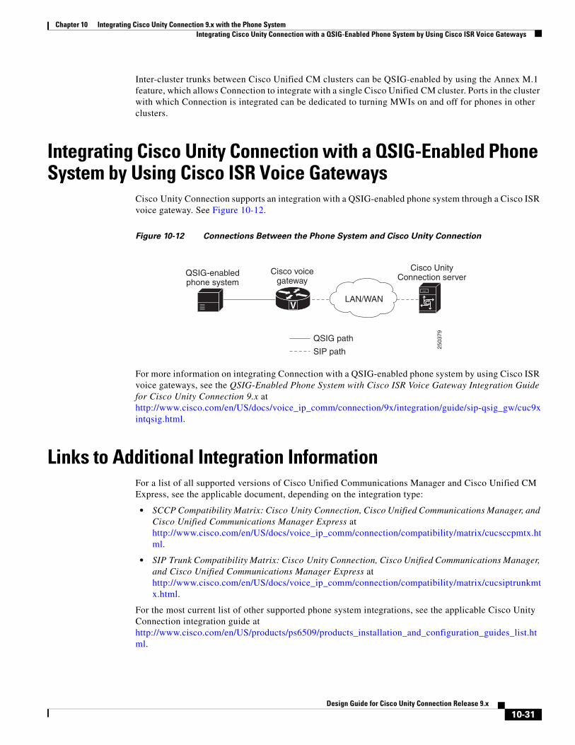
Chapter 10 Integrating Cisco Unity Connection 9.x with the Phone SystemIntegrating Cisco Unity Connection with a QSIG-Enabled Phone System by Using Cisco ISR Voice Gateways
Inter-cluster trunks between Cisco Unified CM clusters can be QSIG-enabled by using the Annex M.1 feature, which allows Connection to integrate with a single Cisco Unified CM cluster. Ports in the cluster with which Connection is integrated can be dedicated to turning MWIs on and off for phones in other clusters.
Integrating Cisco Unity Connection with a QSIG-Enabled Phone System by Using Cisco ISR Voice Gateways
Cisco Unity Connection supports an integration with a QSIG-enabled phone system through a Cisco ISR voice gateway. See Figure 10-12.
Figure 10-12 Connections Between the Phone System and Cisco Unity Connection
For more information on integrating Connection with a QSIG-enabled phone system by using Cisco ISR voice gateways, see the QSIG-Enabled Phone System with Cisco ISR Voice Gateway Integration Guide for Cisco Unity Connection 9.x at http://www.cisco.com/en/US/docs/voice_ip_comm/connection/9x/integration/guide/sip-qsig_gw/cuc9xintqsig.html.
Links to Additional Integration InformationFor a list of all supported versions of Cisco Unified Communications Manager and Cisco Unified CM Express, see the applicable document, depending on the integration type:
• SCCP Compatibility Matrix: Cisco Unity Connection, Cisco Unified Communications Manager, and Cisco Unified Communications Manager Express at http://www.cisco.com/en/US/docs/voice_ip_comm/connection/compatibility/matrix/cucsccpmtx.html.
• SIP Trunk Compatibility Matrix: Cisco Unity Connection, Cisco Unified Communications Manager, and Cisco Unified Communications Manager Express at http://www.cisco.com/en/US/docs/voice_ip_comm/connection/compatibility/matrix/cucsiptrunkmtx.html.
For the most current list of other supported phone system integrations, see the applicable Cisco Unity Connection integration guide at http://www.cisco.com/en/US/products/ps6509/products_installation_and_configuration_guides_list.html.
2503
79
V C
Cisco UnityConnection server
Cisco voicegateway
QSIG-enabledphone system
QSIG path
SIP path
LAN/WAN
10-31Design Guide for Cisco Unity Connection Release 9.x

Chapter 10 Integrating Cisco Unity Connection 9.x with the Phone SystemLinks to Additional Integration Information
Connection can integrate with one or more phone systems at the same time. For details, see the Multiple Phone System Integration Guide for Cisco Unity Connection Release 9.x at http://www.cisco.com/en/US/docs/voice_ip_comm/connection/9x/integration/guide/multiple_integration/cuc9xintmultiple.html.
10-32Design Guide for Cisco Unity Connection Release 9.x


![[Step-by-Step] Cisco Unity Connection SCCP …Step-by-Step] Cisco Unity Connection SCCP Integration with CUCM Cisco Call Manager The optional Cisco Unity Connection server, available](https://img.dokumen.tips/doc/110x75/5ae0402c7f8b9a1c248cf868/step-by-step-cisco-unity-connection-sccp-step-by-step-cisco-unity-connection.jpg)