Embed Size (px)
Citation preview
This article was downloaded by: [Florida State University]On: 25 September 2014, At: 15:47Publisher: Taylor & FrancisInforma Ltd Registered in England and Wales Registered Number: 1072954 Registered office: Mortimer House,37-41 Mortimer Street, London W1T 3JH, UK
International Journal of ControlPublication details, including instructions for authors and subscription information:http://www.tandfonline.com/loi/tcon20
Integrated vehicle control using steering and brakesG. Burgio a & P. Zegelaar aa Ford Motor Company/Research & Advanced Engineering , Aachen, GermanyPublished online: 20 Feb 2007.
To cite this article: G. Burgio & P. Zegelaar (2006) Integrated vehicle control using steering and brakes, International Journalof Control, 79:05, 534-541, DOI: 10.1080/00207170500488970
To link to this article: http://dx.doi.org/10.1080/00207170500488970
PLEASE SCROLL DOWN FOR ARTICLE
Taylor & Francis makes every effort to ensure the accuracy of all the information (the “Content”) containedin the publications on our platform. However, Taylor & Francis, our agents, and our licensors make norepresentations or warranties whatsoever as to the accuracy, completeness, or suitability for any purpose of theContent. Any opinions and views expressed in this publication are the opinions and views of the authors, andare not the views of or endorsed by Taylor & Francis. The accuracy of the Content should not be relied upon andshould be independently verified with primary sources of information. Taylor and Francis shall not be liable forany losses, actions, claims, proceedings, demands, costs, expenses, damages, and other liabilities whatsoeveror howsoever caused arising directly or indirectly in connection with, in relation to or arising out of the use ofthe Content.
This article may be used for research, teaching, and private study purposes. Any substantial or systematicreproduction, redistribution, reselling, loan, sub-licensing, systematic supply, or distribution in anyform to anyone is expressly forbidden. Terms & Conditions of access and use can be found at http://www.tandfonline.com/page/terms-and-conditions
International Journal of ControlVol. 79, No. 5, May 2006, 534–541
Integrated vehicle control using steering and brakes
G. BURGIO* and P. ZEGELAAR
Ford Motor Company/Research & Advanced Engineering, Aachen, Germany
(Received 20 October 2005; in final form 1 December 2005)
The integration of brakes and steering actuators in vehicle lateral dynamics control
is of primary relevance due to the high control authority these actuators insure. Moreoverthis is a challenging control problem as it is MIMO, intrinsically non-linear due to tyrescharacteristic and with high plant uncertainty due to variations of major parameters.
This paper presents the application of state feedback linearization technique to the problemand shows some vehicle test results. The controller results globally stable, smooth and effectivewith the steering actuator and uses the braking correction only in critical cases.
1. Introduction
The vehicle motion control problem has been broadly
addressed in the literature and established solutions
are already in the market.In the brakes stand-alone case, the most common
control approach is linear Proportional and
Proportional Derivative controller (P/PD) like with
gain-scheduling, which guarantees simplicity of design,
affordable in vehicle tuning and robustness, but the
extension of these controllers for the integrated case is
difficult due to their local validity in the neighbourhood
of instability points (van Zanten et al. 1995, 1998). Brake
stand-alone vehicle controllers are at the moment the
most robust solution for improving vehicle stability.The status for steering stand-alone vehicle controllers
is less consolidated.Market available vehicle steering controls are feed
forward like variable gear ratio (where the steering
ratio is changed to higher values for higher vehicle
speed) and �-split braking (compensate with the steering
the yawing coming from the different left–right braking
force) are examples, but the car manufacturers are
clearly interested in steering feedback controllers to
improve handling and stability (Koehn and Eckrich
1998). Plenty of solutions are instead proposed in the
literature, like yaw control with yaw rate-lateral
velocity decoupling (Marino and Conili 2004), or with
yaw rate-lateral acceleration decoupling (Ackermann1990, 1996), or PD based approaches (Kojo et al. 2005).
Vehicle control with steering actuator needs a globallyvalid controller, as it can be continuously active and incase of heavy over/understeering manoeuvres, the steer-ing actuator should correct with heavy countersteeringangles (Koehn and Eckrich 1998).
Regarding integrated control solutions for steeringand brakes (traction), some architecture concepts havebeen studied, like Intelligent Vehicle DynamicsControl (IVDC) (Busch et al. 2003, Weber and Busch2003) or Intelligent Vehicle Motion Control (IVMC)(Crolla et al. 2002) and some heuristic control solutionhave been proposed for the steer-brakes integration(He et al. 2004), but the result was more the sum ofthe stand-alone controllers then a concept integratedcontrol.
The next generation of vehicle controls will focus onthe integration of the stand-alones and the challengefor control systems designers is to propose compactnew solutions for the MIMO control problems resultingfrom the integration of two or more stand-alone con-trollers. The resulting integrated controller will bemore complex than the sum of stand alones, but willguarantee increased performance and robustness.
In this paper the feedback linearization technique isproposed for the design of the base integrated vehiclecontroller, with steering (AFS, SBW) and brakes (orequivalently traction) actuators. The solution is thenshaped in order to satisfy general system requirementsand actuator characteristics, resulting then in a steeringcontroller continuously active, on conditions supported*Corresponding author. Email: [email protected]
International Journal of ControlISSN 0020–7179 print/ISSN 1366–5820 online � 2005 Taylor & Francis
http://www.tandf.co.uk/journalsDOI: 10.1080/00207170500488970
Dow
nloa
ded
by [
Flor
ida
Stat
e U
nive
rsity
] at
15:
47 2
5 Se
ptem
ber
2014
by the brakes controller (i.e. in heavy understeersituations or when too high oversteering brings thevehicle close to instability).The input signals to the controller are standard,
except for the lateral velocity and road friction, whichneed to be estimated. The description of the stateestimator utilized in the project will be addressed in aseparate publication.
2. Vehicle and actuators modelling
The vehicle motion can be in general described as a rigidbody moving in the free space, therefore with 6 dof,connected with the ground surface through tyres andcomplaints, which give to the complete model highnon-linear behaviour and high coupling effects.The actuators for this application are
. active front steer (AFS) or steer by wire (SBW): theseactuators can force an incremental steer angle on topof the driver’s input, independently from this. Thecontrol force is then actuated through the front axletyres characteristic,
. active brakes, where negative longitudinal forces canbe commanded in each of the four wheels (withoutthe sign assumption on the longitudinal forces,traction control can be considered, too).
The plant complexity can be mitigated considering that
. for vehicle handling/stability purposes the mostrelevant dynamics are yaw rate (v ) and lateralvelocity (vy), therefore only 2 dof are considered,
. the brakes actuators are always used to create left–right braking forces differences, therefore the differen-tial braking actuation results in an equivalent yawmoment on the vehicle MB, around its z-axis, withminor direct effect on the lateral velocity dynamics(Nagai et al. 2002).
Therefore, the plant model is the following:
mð _vvyþ vxv Þ ¼� Fyf x,�Dþ �C,Fzf:,kf:� �
þFyr x,Fzr:,kr:ð Þ� �
J _vv ¼� Fyf x,�Dþ �C,Fzf:,kf:� �
lf�Fyr x,Fz:,kr:ð Þlr� �
þMB
)
ð1Þ
where
m vehicle mass (kg)J vehicle inertia momentum (kgm2)
lf, lr front and rear vehicle length (m)vx vehicle longitudinal velocity (m/s)vy vehicle lateral velocity (m/s)v vehicle yaw velocity (rad/s)
x¼ [vy, v ]0 compact vehicle state vector
� maximum tyre-road friction coefficientkij tyres longitudinal slip (front left, front
right, rear left, rear right)Fzij tyres vertical forces (front left, front
right, rear left, rear right) (N)�D driver road wheel angle component
(rad)�C controller road wheel angle component
(rad)MB direct yaw moment, resulting from con-
troller’s active braking (Nm)
and where the �-normalized tyres lateral forces Fyf, Fyr
are functions of tyres slip angles (�f,�r), tyre verticalforces and longitudinal slips, defined as sum of theleft–right components, according to
Fyf x, �D þ �C,Fzf:, kf:� �
¼ Fyf �f,Fzf:, kf:� �
¼ Fyfl �D þ �C �vy þ lfv
vx,Fzfl, kfl
� �
þ Fyfr �D þ �C �vy þ lfv
vx,Fzfr, kfr
� �
Fyr x,Fzr:, kr:ð Þ ¼ Fyr �r,Fzr:, kr:ð Þ
¼ Fyrl �vy � lfv
vx,Fzrl, krl
� �
þ Fyrr �vy � lfv
vx,Fzrr, krr
� �:
8>>>>>>>>>>>>>>>>>>>>><>>>>>>>>>>>>>>>>>>>>>:
ð2Þ
Despite the only lateral force tyre model is considered,the tyre x� y interaction is taken into account withthe parameterization of Fy, function of longitudinal slip.
3. Controller structure
Rewriting the plant equations in state space form, thecontrol problem can be stated asCP: given the plant
_vvy ¼�vxv þ�
mFyf x,�Dþ �C,Fzf:,kf:
� �þFyr x,Fzr:,kr:ð Þ
� �
_vv ¼�
JFyf x,�D,�C,Fzf:,kf:
� �lf�Fyr x,Fzr:,kr:ð Þlr
� �þMB
J
9>>=>>;
ð3Þ
and given a yaw rate target (v d), find the control lawu(x)¼ [�c(x, v R), MB(x, v R)] to insure
1. global stability2. yaw rate tracking: |v d� v |< tolerance3. comfort driving
Integrated vehicle control 535
Dow
nloa
ded
by [
Flor
ida
Stat
e U
nive
rsity
] at
15:
47 2
5 Se
ptem
ber
2014
The last requirement implies that the state variables
must satisfy smoothness conditions therefore the
braking actuators should be seldom activated as every
differential wheel braking action (MB) has negative
effect on comfort.Therefore the following assumptions are made:
A1. as preferred solution the control uses only the
steering actuator;A2. in particular instances, when the steering actuator
is no more enough to control/stabilise the
vehicle according to the desired target, both steer-
ing and brakes actuators need to be managed in
parallel.
The design choice is to first focus on the solution of the
steer only SISO problem, because it will give anyway the
control configuration more often active, therefore most
relevant. A good design of SISO will then lead to the
minimization of the time instances where the multiple
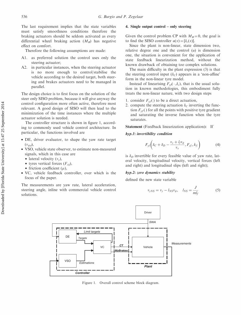
actuator solution is needed.The controller structure is shown in figure 1, accord-
ing to commonly used vehicle control architecture. In
particular, the functions involved are
. DE, driver evaluator, to shape the yaw rate target
(v d),. VSO, vehicle state observer, to estimate non-measured
signals, which in this case are. lateral velocity (vy),. tyres vertical forces (Fzij),. friction coefficient (�),
. VC, vehicle feedback controller, over which is the
focus of the paper.
The measurements are yaw rate, lateral acceleration,
steering angle, inline with commercial vehicle control
solutions.
4. Single output control – only steering
Given the control problem CP with MB¼ 0, the goal isto find the SISO controller u(x)¼ [�c(x)].
Since the plant is non-linear, state dimension two,relative degree one and the control (u) is dimensionone, the situation is convenient for the application ofstate feedback linearization method, without theknown drawback of obtaining too complex solutions.
The main difficulty in the plant expression (3) is thatthe steering control input (�C) appears in a ‘non-affine’form in the non-linear tyre model.
Instead of linearising Fyf( � ,�c), that is the usual solu-tion in known methodologies, this embodiment fullytreats the non-linear nature, with two design steps
1. consider Fyf ( ) to be a direct actuation,2. compute the steering actuation �C inverting the func-
tion Fyf ( ) for all the points with positive tyre gradientand saturating the inverse function when the tyresaturates.
Statement (Feedback linearization application): If
hyp.1: invertibility condition
Fyf �C þ �D �vy þ lfv
vx,Fzf:, kf:
� �ð4Þ
is �D invertible for every feasible value of yaw rate, lat-eral velocity, longitudinal velocity, vertical forces (leftand right) and longitudinal slips (left and right);
hyp.2: zero dynamics stability
defined the new state variable
vyNS ¼ vy � lNSv , lNS ¼J
mlfð5Þ
DE
VC
VSO
Vehicle
Driver
Controller
Plant
Measurements
SWA
Targets
Estimations
MzBrakes
CT
Limit targets
Figure 1. Overall control scheme block diagram.
536 G. Burgio and P. Zegelaar
Dow
nloa
ded
by [
Flor
ida
Stat
e U
nive
rsity
] at
15:
47 2
5 Se
ptem
ber
2014
the solution vyNS(t) of the differential equation
m _vvyNS ¼ �ðlf þ lrÞ
lfFyr �
vyNS þ ðlNS � lrÞv dvx
,Fzr:,kr:
� �
�mvxv d
vyNSð0Þ ¼ 0
8>>>><>>>>:
ð6Þ
is bounded and uniformly asymptotically stable forevery feasible value of the target yaw rate, longitudinalvelocity, vertical forces (left and right) and longitudinalslips (left and right);
then
state feedback linearization (SFL) steering control law
�C ¼ ��D þvy þ lfv
vxþ F�1
yf
1
lflrFyrð�r, :Þ þ
J
�v
� �� �ð7Þ
v ¼ _vv d þ �ðv d � v Þ ð8Þ
is applicable to the problem CP and guarantees stabilityand reference tracking.v d is the target yaw rate, smooth and bounded
function, and �>0.
Proof: From Isidori (1989), SFL steering control law,assuming Fyf be the steering control variable, is
Fyf ¼lrlfFyr þ
1
�lfJv
which, under Hip.1, gives equations (7) and (8) for thesteering control variable �C and guarantees asymptoticstability for the yaw rate tracking error.Moreover, using the new defined state variable vyNS,
the lateral velocity equation in (3) is substituted by
m _vvyNS ¼ �ðlf þ lrÞ
lfFyr �
vyNS þ ðlNS � lrÞv
vx,Fzr:, kr:
� �
�mvxv : ð9Þ
Condition (6) and the asymptotic stability of the yawrate error insure that the above non-controlled dynamicis stable, too. œ
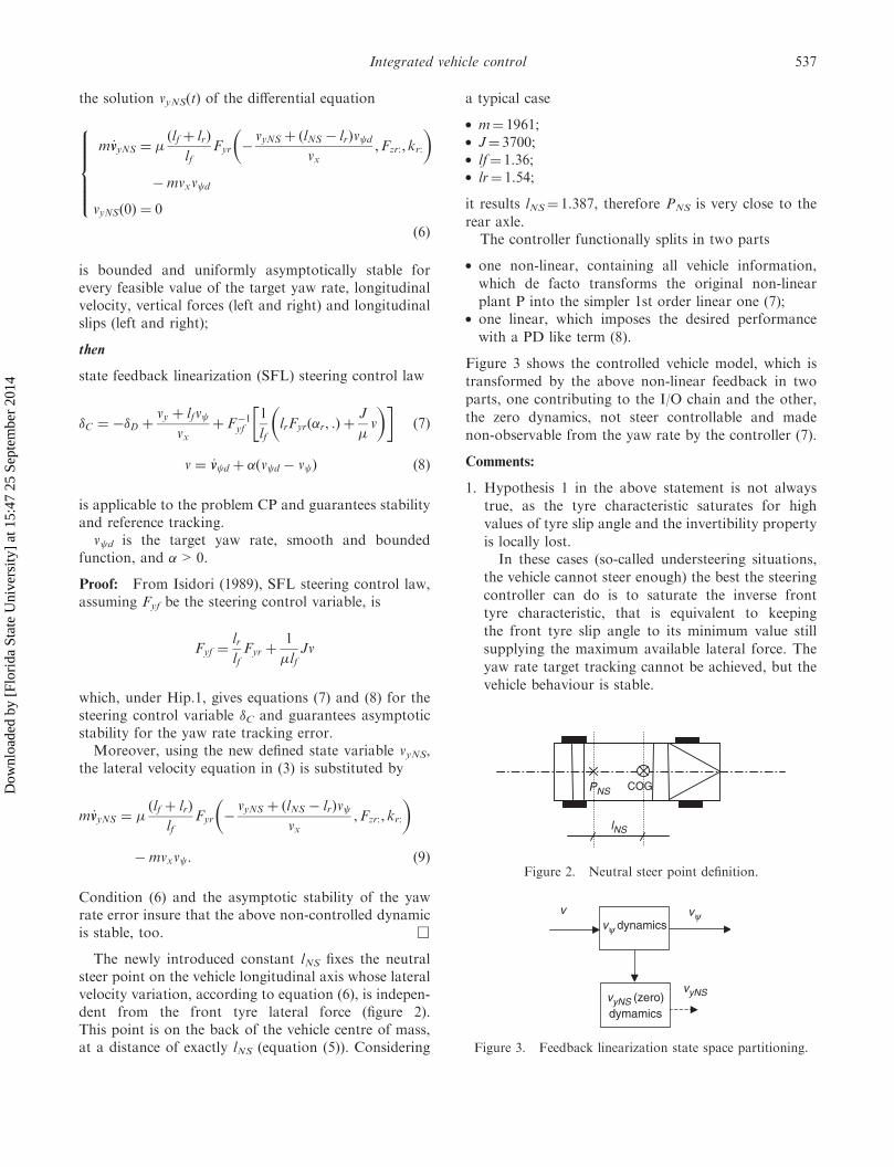
The newly introduced constant lNS fixes the neutralsteer point on the vehicle longitudinal axis whose lateralvelocity variation, according to equation (6), is indepen-dent from the front tyre lateral force (figure 2).This point is on the back of the vehicle centre of mass,at a distance of exactly lNS (equation (5)). Considering
a typical case
. m¼ 1961;
. J¼ 3700;
. lf¼ 1.36;
. lr¼ 1.54;
it results lNS¼ 1.387, therefore PNS is very close to the
rear axle.The controller functionally splits in two parts
. one non-linear, containing all vehicle information,
which de facto transforms the original non-linear
plant P into the simpler 1st order linear one (7);. one linear, which imposes the desired performance
with a PD like term (8).
Figure 3 shows the controlled vehicle model, which is
transformed by the above non-linear feedback in two
parts, one contributing to the I/O chain and the other,
the zero dynamics, not steer controllable and made
non-observable from the yaw rate by the controller (7).
Comments:
1. Hypothesis 1 in the above statement is not always
true, as the tyre characteristic saturates for high
values of tyre slip angle and the invertibility property
is locally lost.In these cases (so-called understeering situations,
the vehicle cannot steer enough) the best the steering
controller can do is to saturate the inverse front
tyre characteristic, that is equivalent to keeping
the front tyre slip angle to its minimum value still
supplying the maximum available lateral force. The
yaw rate target tracking cannot be achieved, but the
vehicle behaviour is stable.
vyNS (zero)dymamics
vvy dynamics
vy
vyNS
Figure 3. Feedback linearization state space partitioning.
COGPNS
lNS
Figure 2. Neutral steer point definition.
Integrated vehicle control 537
Dow
nloa
ded
by [
Flor
ida
Stat
e U
nive
rsity
] at
15:
47 2
5 Se
ptem
ber
2014
2. Hypothesis 2 is valid if the rear tyres are not saturat-ing, as Fyr is a monotonically increasing function ofvyNS, but if saturation occurs and �lFyrð�Þ <lfmvxv , then the state vyNS integrally diverges.This shows a physical limit of the system, indepen-
dent from the adopted steering control. From thevehicle dynamics point of view, it means that theequilibrium of the state vyNS is obtained only whenthe force generated by the rear tyres balances the cen-trifugal force. But the centrifugal force grows withthe yaw rate and the vehicle longitudinal speed, isunbounded, while tyre force is limited by the tyrecharacteristic; therefore if the yaw rate or the longitu-dinal speed are too high, the lateral velocity in thepoint PNS will integral like diverge. This eventneeds to be avoided either limiting the longitudinalspeed or limiting the target yaw rate, otherwise thevehicle will spin.
3. The available friction coefficient � is used in the feed-back loop to divide the target yaw moment, thereforeresulting in higher feedback gain for low � values.This is not in line with the fact that, in slipperysurfaces, the experienced driver gives smoothersteering corrections. Therefore the above divisionis avoided, resulting then in a lower controllerbandwidth for low �.
Both hypotheses for applicability of SFL steering con-troller are related to the saturation of front or reartyre, in particular the saturation of the front tyre isrelated to the performance of the yaw tracking (loss ofcontrollability) while the saturation of the rear tyre isrelated to stability. These are properties well known tovehicle dynamics experts.
5. Multiple output control – steering and brakes
The multiple output control approach extends the pro-posed SISO design with the objective of obtaining afull state control which properly integrates the brakesaction on the defined steering controller, still satisfyingthe assumptions A1, A2.A natural choice for the integrated controller is
that the additional brakes actuator action inu(x)¼ [�c(x),MB(x)] is chosen to support the caseswhen the applicability hypothesis 1, 2 are not valid.
. The active steering control law �c(x) is chosen accord-ing to (7), (8) in all the cases the steering actuator canprovide good yaw rate tracking and vehicle stability,i.e. when the front and rear tyres are not saturating.This is in line with the previously stated ‘‘steeringpriority’’ assumption.
. If the front tyres saturate and the yaw control systemis still asking for higher lateral forces, then the braking
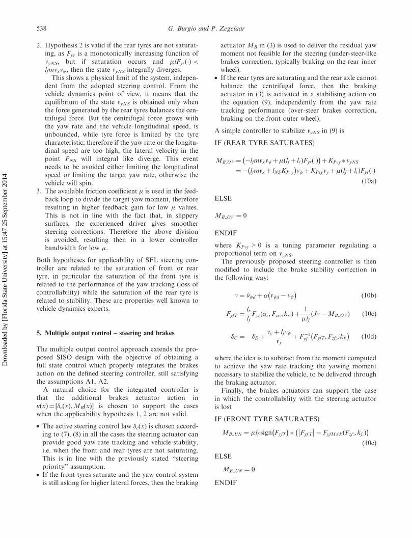
actuator MB in (3) is used to deliver the residual yawmoment not feasible for the steering (under-steer-likebrakes correction, typically braking on the rear innerwheel).
. If the rear tyres are saturating and the rear axle cannotbalance the centrifugal force, then the brakingactuator in (3) is activated in a stabilising action onthe equation (9), independently from the yaw ratetracking performance (over-steer brakes correction,braking on the front outer wheel).
A simple controller to stabilize vyNS in (9) is
IF (REAR TYRE SATURATES)
MB OV ¼ �lfmvxv þ�ðlfþ lrÞFyrð�Þ� �
þKPvy � vyNS
¼� lfmvxþ lNSKPvy
� �v þKPvyvyþ�ðlfþ lrÞFyrð�Þ
ð10aÞ
ELSE
MB OV ¼ 0
ENDIF
where KPvy>0 is a tuning parameter regulating aproportional term on vyNS.
The previously proposed steering controller is thenmodified to include the brake stability correction inthe following way:
v ¼ _vv d þ � v d � v � �
ð10bÞ
FyfT ¼lrlfFyr �r,Fzr:, kr:ð Þ þ
1
�lfJv�MB OVð Þ ð10cÞ
�C ¼ ��D þvy þ lfv
vxþ F�1
yf FyfT,Fzf:, kf:� �
ð10dÞ
where the idea is to subtract from the moment computedto achieve the yaw rate tracking the yawing momentnecessary to stabilize the vehicle, to be delivered throughthe braking actuator.
Finally, the brakes actuators can support the casein which the controllability with the steering actuatoris lost
IF (FRONT TYRE SATURATES)
MB UN ¼ �lf sign FyfT
� �� FyfT
�� ��� FyfMAXðFzf:, kf:Þ� �
ð10eÞ
ELSE
MB UN ¼ 0
ENDIF
538 G. Burgio and P. Zegelaar
Dow
nloa
ded
by [
Flor
ida
Stat
e U
nive
rsity
] at
15:
47 2
5 Se
ptem
ber
2014

and this results in recovered vehicle controllability thatmakes the vehicle more agile, in particular in slipperysurfaces where the front tyre saturation is easily reached.The total brake correction will be then the sum of the
oversteer and understeer corrections
MB ¼ MB UN þMB OV ð10fÞ
The target front tyre force introduced in (10c) is�-normalized, like tyre forces in the entire article:this makes the controller entirely defined parameterizedon �, and this makes easy the integration with a �estimator to enhance the performance on slipperysurfaces.Despite the proposed controller requiring the knowl-
edge of the friction coefficient, the required accuracy isnot high, as
. in the steering controller (7) the dependency on �affects the only linear part, in particular a lower �results in higher P controller gain. This division canbe avoided, resulting in lower controller bandwidthfor slippery surfaces,
. in the stability brakes controller (10a) one canrecognize a feedforward-like term � dependant,where an underestimation can be used, plus a propor-tional term on the state vyNS to improve robustness ofthe stability correction, which is � independent,
. the front tyre saturation brakes correction is propor-tional to �, but this correction (namely, understeeringcorrection) is less important then the others does notaffect stability and is an add on the FL solution toenhance performance, therefore an underestimationof � can be used.
The same controller can be found applying MIMO feed-back linearization design method to the vehicle modeland slightly modifying the brakes control law, accordingto assumption A2.The vehicle model (3) is written in the form
_xx ¼ f ðxÞ þ gðxÞu
with
x ¼
v
vyNS
" #; u ¼
Ffy
MB
" #
fðxÞ ¼
��lrJ
Fyr
�l
mlfFyr � vxv
26664
37775; gðxÞ ¼
�lfJ
1
J
0 �1
mlf
26664
37775
9>>>>>>>>>>=>>>>>>>>>>;ð11Þ
The related full FL MIMO vehicle controller is:
u ¼ gðxÞ�1ðv� f ðxÞÞ
therefore
Fyf
MB
� �¼
J
�lf
m
�0 �mlf
24
35 v1
v2
� �þ
�lrJ
Fyr
��l
mlfFyr þ vxv
264
375
0B@
1CA
ð12Þ
which can be rewritten in the form
Fyf ¼lrlfFyr þ
1
�lfJv1 �MBð Þ
MB ¼ �lFyr �mlfvxv �mlfv2
9=; ð13Þ
with the linear tracking terms
v1 ¼ _vv d þ �1 v d � v � �
v2 ¼ _vvyNSd þ �2 vyNSd � vyNS
� �)
ð14Þ
The controller (13), (14) guarantees tracking of thetarget [v d, vyNSd] and global asymptotic stability underthe assumption of front tyre invertibility (4) and brakingactuation effectiveness.
The equations of the controlled vehicle are in this case
_vv e ¼ ��v e
_vvyNS ¼ �KPvy
mlfvyNS
9>=>; ð15Þ
with both states asymptotically stable, i.e.
v ) v d, vyNS ) vyNSd: ð16Þ
This controller isn’t in line with the design assumptionsA1, A2, as it would require a continuous direct yawmoment Mz activation (the actuator pair active steeringand active differential would be a better choice for thiscontroller).
With the relaxed goal of only stabilizing instead oftracking vyNS, the brakes control law (13), (14) can berewritten, assuming vyNSd¼ 0, dvyNSd/dt¼ 0, as
MB ¼ �lFyr �mlfvxv þmlf �2vyNS ð17Þ
which is equivalent to the already proposed form (10a).The brakes controller should be only activated over limitvalues of vyNS, to be defined in the tuning phase.
Integrated vehicle control 539
Dow
nloa
ded
by [
Flor
ida
Stat
e U
nive
rsity
] at
15:
47 2
5 Se
ptem
ber
2014
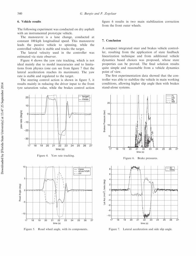
6. Vehicle results
The following experiment was conducted on dry asphaltwith an instrumented prototype vehicle.The manoeuvre is a lane change, conducted at
constant 100 kph longitudinal speed. This manoeuvreleads the passive vehicle to spinning, while thecontrolled vehicle is stable and tracks the target.The lateral velocity used in the controller was
estimated via state observer.Figure 4 shows the yaw rate tracking, which is not
ideal mainly due to model inaccuracies and to limita-tions from physics (one can see from figure 7 that thelateral acceleration reaches its maximum). The yawrate is stable and regulated to the target.The steering control action is shown in figure 5, it
results mainly in reducing the driver input to the fronttyre saturation value, while the brakes control action
figure 6 results in two main stabilization correction
from the front outer wheels.
7. Conclusion
A compact integrated steer and brakes vehicle control-
ler, resulting from the application of state feedback
linearization technique and from additional vehicle
dynamics based choices was proposed, whose state
properties can be proved. The final solution resultsquite simple and reasonable from a vehicle dynamics
point of view.The first experimentation data showed that the con-
troller was able to stabilize the vehicle in main working
conditions, allowing higher slip angle then with brakesstand-alone systems.
17 18 19 20 21 22 23 24 25 26 270
5
10
15
20B
rake
s P
ress
ure
(bar
)
time (s)
FLFRRLRR
Figure 6. Brake pressures.
17 18 19 20 21 22 23 24 25 26 27
−30
−20
−10
0
10
20
yaw
rat
e (d
eg/s
)
time (s)
targetmeas
Figure 4. Yaw rate tracking.
17 18 19 20 21 22 23 24 25 26 27
−10
−5
0
5
10
Roa
d A
ngle
(de
g)
time (s)
measdriver/VGRctrl
Figure 5. Road wheel angle, with its components.
17 18 19 20 21 22 23 24 25 26 27
−10
−8
−6
−4
−2
0
2
4
6
8
Lat A
cc (
m/s
2 ), b
eta
(deg
)
time (s)
aybeta
Figure 7. Lateral acceleration and side slip angle.
540 G. Burgio and P. Zegelaar
Dow
nloa
ded
by [
Flor
ida
Stat
e U
nive
rsity
] at
15:
47 2
5 Se
ptem
ber
2014
Acknowledgements
This work was developed within IVDC project activitiesin FFA. The authors would like to thank the completeIVDC3 team for the interesting discussions on thevehicle dynamics aspects and for all the additionalparallel teamwork, which made possible writing thispaper.
References
J. Ackermann, ‘‘Robust car steering by yaw rate control’’, CDC,1990.
J. Ackermann, ‘‘Robust control prevents car skidding’’, Bode Prize,1996.
R. Busch, Seibertiz and P. Schmitz, ‘‘IVDC – the development of inte-grated vehicle dynamics control’’, VDI, 2003.
J. He, D.A. Crolla, M.C. Levesley and W.J. Manning, ‘‘Integratedactive steering and variable torque distribution control for improv-ing vehicle handling and stability’’, SAE, 2004.
A. Isidori, Nonlinear Control Systems, 2nd ed., Heidelberg, Springer-Verlag.
P. Koehn and M. Eckrich, ‘‘Active steering – the bmw approachtowards modern steering technology’’, 1989.
T. Kojo, M. Suzumura and Y. Tsuchiya, ‘‘Development of active frontsteering control system’’, SAE, 2005.
W.J. Manning, M. Selby, D.A. Crolla and M.D. Brown, ‘‘IVMC:intelligent vehicle motion control’’, 2002.
R. Marino and F. Cinili, ‘‘Yaw rate decoupling control in activesteering vehilces’’, IFAC, 2004.
M. Nagai, M. Shino and F. Gao, ‘‘Study on integrated controlof active front steer angle and direct yaw moment’’, SAE,Japan, 2002.
A. van Zanten, R. Erhardt and G. Pfaff, ‘‘VDC, the vehicle dynamicscontrol system of bosch’’, SAE, 1995.
A. van Zanten, R. Erhardt, K. Landesfeind and G. Pfaff, ‘‘VDCsystem development and perspective’’, SAE, 1998.
K. Webers and R. Busch, Ford Integrated Vehicle Dynamics Control:Concept, Munchen: TuV, Fahrwerk. Tech., 2003.
Integrated vehicle control 541
Dow
nloa
ded
by [
Flor
ida
Stat
e U
nive
rsity
] at
15:
47 2
5 Se
ptem
ber
2014