Embed Size (px)
Citation preview
Integrated project support environments
Integrated project support systems facilitate large, long-lifetime software developments, which are increasingly common in microprocessor projects. lan Sommen ille illustrates these systems with reference to one particular
first-generation I PSE
The paper presents an overview of integrated project s u p p o r t environments (IPSEs) which a r e software develop- ment environments intended to support large, long- lifetime s o f t w a r e projects. The logical structure of a n IPSE is discussed from the view that the IPSE is a set of layered facilities. Each layer in the s e t is described. Standardization is important for future IPSE development and standard public tool interfaces a re discussed. Common ADA programming support environment interface s e t (CAIS) and portable common tool environment (PCTE) a r e introduced. Examples of tool and user interface integration in an IPSE a r e provide d using the Eclipse IPSE as a n exemplar. Deficiencies in current systems and future developments in this a rea a re addressed.
microsystems software development environments IPSEs Edipse
The high cost and the difficulties of developing software systems are well known. Accordingly, as the costs of computer hardware have decreased, it has become more and more cost-effective to provide individual software engineers with automated tools to support the software development process. Although it is possible to operate software tools (now sometimes called CASE tools) in conjunction with application systems, it is generally the case that the activity of software developments is best supported on a separate system which is termed a software development environment (SDE).
A software development environment may be defined as follows:
A collection of software and hardware tools which is explicitly tailored to support the production of software systems in a particular application domain.
There are two important points to highlight in this
Department of Computing, University of Lancaster, Lancaster LA1 4YR, UK Paper received: 19 December 1988. Revised: 30 January 1989
definition. Firstly, the software development environment may include hardware tools. For example, microprocessor development systems, which will be familiar to many readers of this journal, often include an in-circuit emulator as an integral part of the environment. Secondly, the software development environment is specific rather than general. It is intended to support the development of a particular class of systems, such as microprocessor systems, and does not contain facilities to support all types of application systems development.
There are, in fact, many different types of software development environment which are now in use. Some examples are:
• Microprocessor development systems. These are intended to support the development of embedded software for a particular microprocessor or family of microprocessors. They include facilities such as in-circuit emulators, cross-compilers, remote debuggers etc. in addition to program preparation tools.
• Language-oriented programmingenvironments. These are environments geared towards the support of programs in a particular programming language such as PASCAL or C. Of course, the simplest language-oriented environments are those for BASlC provided on many personal computers, but more sophisticated environ- ments include very specific language processing tools. A characteristic of such environments is that they include knowledge of the language under develop- ment and, so, can provide more 'intelligent' support for the development process. Such environments are often created by adding language-oriented facilities to general-purpose kernel environment such as Gandalf I .
• Knowledge-based systems development environments. These environments, typified by systems such as ART or KEE, are generally language-oriented environments with additional very high-level facilities that are specifically intended for creating knowledge-based systems.
• Integrated project support environments. This class of SDE is intended to support the production of large,
0141-9331/89/04254-09 $03.00 © 1989 Butterworth & Co. (Publishers) Ltd
254 Microprocessors and Microsystems

long-lifetime software systems whose maintenance costs typically exceed development costs and which are produced by a team rather than by individual programmers.
The range of different types of SDE is such that it is not possible to discuss all of these in a single paper. Accordingly, this paper is concerned with integrated project support environments (IPSEs) which, currently, are geared towards large systems development. In principle, such systems could also be useful for supporting the development of smaller systems but, at present, their relatively high cost means that their use is confined to large projects.
An integrated project support environment may be defined as follows:
A collection of hardware and software tools which can act in combination in an integrated way and which supports the configuration management of all of the products of the software development process. The environment should provide support for all of the activities in the software process from initial specification through to testing and system delivery.
The key points in this definition are:
• The environment facilities are integrated. Three types of integration can be identified, namely data integration, interface integration and activity integration. Data integration means that tools can exchange data, that is the outputs from one tool can act as inputs to some other tool. User interface integration means that the different facilities in the environment present a con- sistent interface to the user. Activity integration means that the environment includes embedded knowledge of its tools and of the software process, and can automatically schedule and control development activities. Current environments support data inte- gration and interface integration but activity integration is still a research topic.
• All products may be subjected to configuration management. The most expensive activity in managing long-lifetime systems is ensuring that, for all versions of the system, all of the documents associated with a version (specifications, design, code, user documen- tation etc.) are consistent. This is called configuration management and automated support for this process is an essential part of an IPSE.
• Facilities are available to support all software develop- ment activities. This characteristic is a side effect of the requirement that all products and documents should be managed by the IPSE. If automated management is essential, the IPSE must provide support for all software development activities. Thus, the tools available in an IPSE should support specification, design, documen- tation, programming, testing, debugging etc.
At the time of writing, a number of first generation IPSE systems are commercially available. These include Istar 2, Genos 3, Eclipse 4 and Bis-IPSE s from UK suppliers and systems such as Epos 6 and Maestro from European suppliers. By contrast with developments in Europe, IPSE work in the USA has tended to concentrate on the development of IPSEs, such as the Rational environment, which are tailored to support systems written in the programming language ADA. ADA Was designed for writing large-scale embedded systems and is a USA and NATO defence standard. ADA-Oriented IPSEs are often called APSEs (ADA programming support environments). The
/ J
/
Downloaded program
I Figure 1. Host-target systems
examples in this paper are drawn from the Eclipse environment as the author was involved in the develop- ment of that system.
Current IPSEs generally assume a host-target model of software development (Figure 1) where a dedicated system is used for software development and the software is executed on some other target system. Such a model will be familiar to users of microprocessor develop- ment systems where it is the normal mode of working. However, it should not be assumed that this model of working is necessarily the best one for all types of system. Although it is clearly necessary for embedded system construction, there are many classes of application system which could make effective use of the facilities provided in an IPSE. Future generations of IPSEs may well have operational modes which allow them not only to support the development of application systems but also to support these systems whilst they are in execution.
LOGICAL STRUCTURE OF AN IPSE
The current generation of IPSEs exhibit a variety of structures but share a common logical structure where tools and user interface facilities are integrated around a kernel providing data and object management primitives. A simplified model of this structure is shown in Figure 2. This model is simplified because the layering in actual systems is indistinct and tools may interact directly with the data management and operating systems. Further-
toolset
Figure 2. Structure of an IPSE
Vol 73 No 4 May 1989 255

may be built directly on top of a file system or using a database management system. The object management facilities are a logical interface which is independent of this implementation and need not be changed if the underlying data management layer is reimplemented.
The role of the object management layer is to provide basic primitives which allow configuration management to be implemented. A configuration management system is concerned with the different versions of system documents, including specifications, designs, code, test data, manuals etc., and the maintenance of the relation- ships between these versions. Therefore, the OMS should provide a means of creating objects whose type reflects development process types. Thus types supported by the OMS might be 'PASCAL code', 'Mascot design' etc. which map onto underlying data management types such as 'Text' or 'Diagram'. Furthermore, the OMS should provide facilities allowing attributes such as 'creator', 'creation date' etc. to be associated with objects.
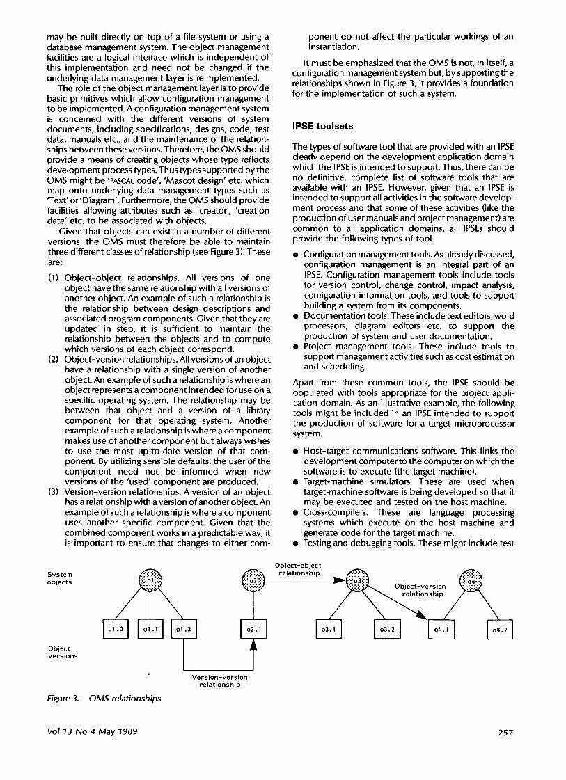
Given that objects can exist in a number of different versions, the OMS must therefore be able to maintain three different classes of relationship (see Figure 3). These are:
(1) Object-object relationships. All versions of one object have the same relationship with all versions of another object. An example of such a relationship is the relationship between design descriptions and associated program components. Given that they are updated in step, it is sufficient to maintain the relationship between the objects and to compute which versions of each object correspond.
(2) Object-version relationships. All versions of an object have a relationship with a single version of another object. An example of such a relationship is where an object represents a component intended for use on a specific operating system. The relationship may be between that object and a version of a library component for that operating system. Another example of such a relationship is where a component makes use of another component but always wishes to use the most up-to-date version of that com- ponent. By utilizing sensible defaults, the user of the component need not be informed when new versions of the 'used' component are produced.
(3) Version-version relationships. A version of an object has a relationship with a version of another object. An example of such a relationship is where a component uses another specific component. Given that the combined component works in a predictable way, it is important to ensure that changes to either com-
System objects
Object versions
Figure 3. OMS relationships
Version-version relationship
ponent do not affect the particular workings of an instantiation.
It must be emphasized that the OMS is not, in itself, a configuration management system but, by supporting the relationships shown in Figure 3, it provides a foundation for the implementation of such a system.
IPSE t o o l s e t s
The types of software tool that are provided with an IPSE clearly depend on the development application domain which the IPSE is intended to support. Thus, there can be no definitive, complete list of software tools that are available with an IPSE. However, given that an IPSE is intended to support all activities in the software develop- ment process and that some of these activities (like the production of user manuals and project management) are common to all application domains, all IPSEs should provide the following types of tool.
• Configuration management tools. As already discussed, configuration management is an integral part of an IPSE. Configuration management tools include tools for version control, change control, impact analysis, configuration information tools, and tools to support building a system from its components.
• Documentation tools. These include text editors, word processors, diagram editors etc. to support the production of system and user documentation.
• Project management tools. These include tools to support management activities such as cost estimation and scheduling.
Apart from these common tools, the IPSE should be populated with tools appropriate for the project appli- cation domain. As an illustrative example, the following tools might be included in an IPSE intended to support the production of software for a target microprocessor system.
• Host-target communications software. This links the development computer to the computer on which the software is to execute (the target machine).
• Target-machine simulators. These are used when target-machine software is being developed so that it may be executed and tested on the host machine.
• Cross-compilers. These are language processing systems which execute on the host machine and generate code for the target machine.
• Testing and debugging tools. These might include test
Object-object relationship ~ , ~
J ' ~ ~ Object-vers!on
Vol 13 No 4 May "!989 257
drivers, dynamic and static program analysers, and test output analysis programs. Debugging of the host of programs executing on the target should be supported if possible.
• Graphical design editors. These are editing systems which allow the graphical representation of a design to be edited and which are tailored to support a realtime method such as Mascot 7 or Darts 8. The editors should incorporate design knowledge and should not simply be diagram editors.
Different levels of tool integration can be achieved within an IPSE. Ideally, tools should be tightly integrated with the OMS so that they work with system objects rather than more primitive entities such as files. If this is the case, configuration management procedures can be enforced automatically by the tools. However, it is currently an unrealistic requirement that all tools must be tightly integrated with the OMS, as this precludes the use of tools that have been written for general use rather than use within a specific IPSE. Thus, IPSEs must support a foreign tool interface whereby tools can check-out objects from the IPSE into their own data space, operate on these objects and then check the transformations back into the IPSE data space.
A relatively recent tool development, which has become possible with the availability of low-cost personal computers, is CASE toolsets. These are graphical tools which are intended to support a software development method and, as these systems develop, they are acquiring I PSE capabilities. To date, they have been applied mostly in the commercial systems domain. Space does not permit a discussion of these tools in this paper. Readers interested in this topic are referred to the edition of IEEE Software on this topic which is included in the further reading list.
User interface
It is now accepted that an effective user interface to a system is critical if that system is to be accepted by users and make a significant contribution to the software development process. IPSEs are inherently large and complex systems and a good user interface is essential.
The IPSE user interface is an important integrating mechanism in that a common and consistent user interface provided across IPSE facilities reduces the software engineer's learning time when a new tool is used and reduces the probability of mistakes when switching from one tool to another. The reduction in user errors is particularly important because IPSE tools often carry out similar tasks on different types of object. There may be different editors for plain text, program text and graphics and, if these editors have different ways of initiating the same operation (such as delete), it is inevitable that a user will confuse the interface operations.
User interfaces fall into two classes:
(1) Interfaces that can be provided on devices with limited processing power. Typically, there are conventional character-oriented terminals with very limited graphics facilities. The display device constrains the interface designer to a character- oriented interface.
(2) Interfaces that can be provided on workstations with significant inbuilt processing power and, usually, a
high-resolution graphics screen and a mouse. Such interfaces may be so-called WlMP interfaces, standing for Windows, Icons, Mice and Pointing.
Although it is clear that the software industry is moving towards development environments that are based on networked workstations, there is still an immense invest- ment in character terminals linked to central computing systems. Some IPSE vendors have chosen to address this market and have based their IPSE interface on a character interface.
By contrast, in some IPSEs, such as Eclipse, a decision was made early in the system's development that the constraints imposed by character interfaces were so great that only workstation interfaces would be supported. In the same way as vendors of engineering CAD systems do not provide facilities on inadequate hardware, it seems reasonable that a comparable decision should be made by vendors of systems to support software engineering.
A number of problems must be faced by IPSE user interface designers.
• IPSE users make up a very heterogeneous community. They range from highly experienced software engineers who use the system several hours per day, through software managers who make occasional use of the system, to secretarial staff with little computing background or experience.
• The nature of software project developments is such that staff may have to work with a number of different development systems. It is important that their inter- face is such that learning time is minimized.
• The range and functionality of tools hosted by the IPSE is very wide. Provision of an integrating approach across these functionalities is very difficult.
• The structures which are created in the IPSE database are complex and provision of a comprehensible model of these to the user is difficult.
WlMP interfaces that make use of direct manipulation techniques, as discussed by Shneiderrnan 9, allow the user access to IPSE facilities via pointing and menus and do not require a complex command language to be learned. For most IPSEs, such an approach is probably the most effective in supporting the diverse UI requirements. Interface integration as provided in the Eclipse IPSE is discussed later.
PUBLIC TOOL INTERFACES AND STANDARDIZATION
The notion of a public tool interface as a standard for an IPSE data and object management system has already been introduced. In this section, this notion is discussed in more detail together with the important question of standardization.
The initial proposal for what is now called a public tool interface was put forward by Buxton 1° in a document setting out requirements for a support environment for ADA. In that document, he proposed the notion of an ADA programming support environment (APSE) which was layered with the innermost layer being a so-called kernel APSE. This kernel APSE would insulate the environment facilities from the underlying hardware, operating system and data management facilities, and would provide object management primitives.
2.58 Microprocessors and Microsystems
After a number of environment projects were un- successful, a working party in the USA (with European representatives) was set up to a define a kernel APSE interface standard and this became known as the CAIS (common APSE interface set) standard. The initial version of this standard (CAIS-1) was technically deficient in a number of ways (e.g. it lacked any distribution support, support for user-defined typing, or support for bit- mapped workstations) and a revised version of this standard was due for completion in early 1989. An overview of CAIS-I is presented in Reference 11.
In parallel with the American CAIS work, the European Commission funded a multinational project under the Esprit programme to define a comparable public tool interface. This was called PCTE (portable common tool environment) 12 and the first version of the PCTE was published in 1984. By contrast with the CAIS standard which was ADA oriented, the PCTE standard was Unix and c oriented and was intended for general-purpose rather than language-oriented environment support. Initial implementations of the PCTE were completed in 1985 and implementations are now available on a number of workstations.
The author is not aware of commercially available environments based on CAIS, butthe Eclipse environment which was funded by the British Alvey programme has been built on top of PCTE. It is clear that PCTE also suffers from a number of technical deficiencies and work is now underway to produce a revision of this interface.
Space does not allow a detailed description of either the PCTE or the CAIS and there are obviously marked differences between these environments. However, as the revised version of the CAIS is likely to have much in common with the PCTE it is appropriate to consider general facilities that are provided in the PCTE and which are likely to be part of CAIS-2.
In terms of the above layered model, the PCTE defines both the data management and the object management layers, although the data management facilities are less complete than those included in a generalized DBMS. Object management is based on an entity relationship attribute (ERA) model where objects are represented by database entities, may participate in relationships with other objects, and may have inherent attributes. A similar model is used in the CAIS. Unlike CAIS-1, however, PCTE entities are typed and user-defined subtyping is supported. For example, from a basic type Text, it is possible to derive subtypes such as PASCAL-Source-Text. This specific typing allows tools to check that the objects that they manipulate are indeed of the correct type and thus the scope for error is reduced.
As well as object management facilities, the PCTE also provides facilities for execution management allowing processes to be started, terminated and controlled; facilities for interprocess communication including standard Unix pipes and signals, message passing and shared memory; and I/O facilities comparable with those provided in Unix.
To provide data recovery and resilience, the PCTE supports the notion of transactions where a transaction is an atomic set of actions whose effect on data is either to apply all or none of these actions. This means that if a failure occurs during the transaction, it is possible to restore the database to a consistent state.
Both process and OMS distribution are supported in the PCTE. It has been recognized that development environ-
ments are likely to be built using a network of work- stations and it is possible to distribute executing processes across this network. Thus, a process controlling a number of compilations, say, could set each compilation off in different network workstations. Similarly, data need not all reside in a single system but may be distributed over different nodes in the network.
The PCTE provides a number of user interface primitives which are designed for controlling bit-mapped work- stations and, in fact, a complete model of user interaction has been defined. However, a more general standard in this area is emerging (X-windows 13) and it is possible that the next revision of the PCTE will incorporate this standard rather than the existing primitives. This change will have little effect on existing implementations of the PCTE as these have tended to exclude the PCTE UI primitives. Workstation tools that have been built use the basic interaction primitives produced by the workstation manufacturer.
The PCTE suffers from a number of detailed technical deficiencies, particularly in its model of transaction and distribution, which it is not appropriate to discuss here. However, its most significant general deficiency is its lack of access control over and above the simple Unix facilities. This means that the PCTE is not an adequate basis for the construction of secure systems (as required by the military, for example) and efforts are underway (the NATO-funded PCTE+ project) to define how such access control facilities can be included in the PCTE.
The PCTE and CAIS efforts represent important steps to standardization in the area of public tool interfaces and it is clear that some standards are essential if third-party vendors are to produce tools which can be integrated with an IPSE. Furthermore, PTI standards will mean that the costs of porting complete IPSEs from one machine to another will be reduced. This will ultimately increase the availability and reduce the costs of IPSEs.
Unfortunately, international political considerations will perhaps mean that a single standard will not emerge from the convergence of the CAIS and the PCTE efforts. Logically, these systems are sufficiently similar for a common standard to be produced but given that they were derived in the US and Europe respectively, it is probably optimistic to expect agreement to be reached.
TOOL INTEGRATION
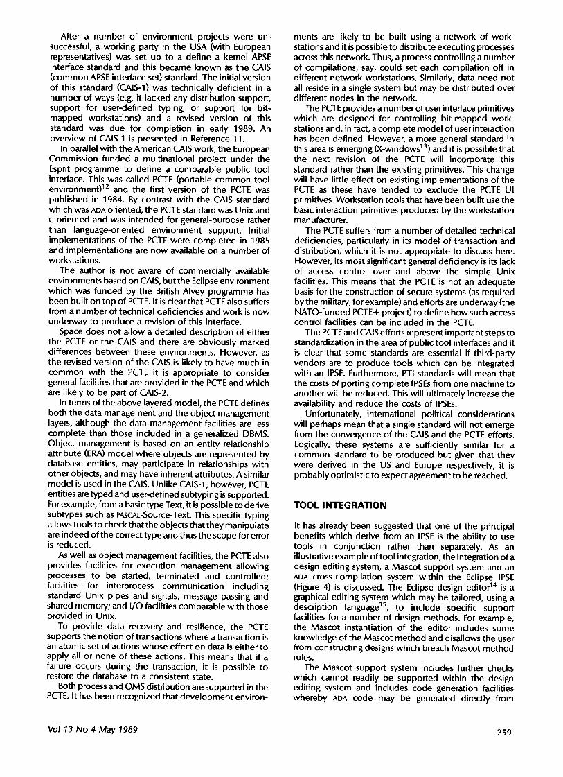
It has already been suggested that one of the principal benefits which derive from an IPSE is the ability to use tools in conjunction rather than separately. As an illustrative example of tool integration, the integration of a design editing system, a Mascot support system and an ADA cross-compilation system within the Eclipse IPSE (Figure 4) is discussed. The Eclipse design editor TM is a graphical editing system which may be tailored, using a description language is, to include specific support facilities for a number of design methods. For example, the Mascot instantiation of the editor includes some knowledge of the Mascot method and disallows the user from constructing designs which breach Mascot method rules.
The Mascot support system includes further checks which cannot readily be supported within the design editing system and includes code generation facilities whereby ADA code may be generated directly from
Vol 13 No 4 May 1989 259
J J ' I ~d " ~, / r • ~, f Interactive Echpse... ] | .Mascot ] [ADA development]
eslgn e o , , o r j ~ ~ system j /
======================:i:i:i::~i~::::i~i~i:i:i:!~:!~!~!~!~!~!~!~!:i~!:i~i:i:i:i:~.i~?i~i:i~i~!~:::::::::::::::::::::::::::::::::::::::::: "::::::::::::::::::::!i!i!!iii!!!!i!!i!i:~ i: D e s i g n !:i:!:!:!:!:!:! ADA p a c k a g e :i:i:i:i: iiii:i:i:i:i:iii:i:i:i: :: . 1:::::::::::::: • . , ::::::::: A D A l ibrary =======================
i i i i i i i iii i ii i iiiii ii ? ci I ; ;: ag ;Z e i iiiiiii iiiiiiiiiiiiiiiiiiiii iiiiiiiiiiiiiiiiiiiiiiiiiiiii iii i
Figure 4. Tool integration in Eclipse
Mascot design specifications. Although it is not possible, in general, to generate control information, ADA package specifications can be constructed automatically.
The interactive ADA development system (lADS) is an ADA cross-development system for Intel 8086 and 80286 processors that includes ADA compilation facilities, program downloading, and host test and debugging facilities. The code generated by the Mascot support system can be passed directly to lADS for compilation.
Using the design editor, a user creates a Mascot design (some of which is checked by the editor) and saves this design in the database. The Mascot tool system interro- gates this structure, performs further checking and generates ADA package specifications for the design entities. Again, these are recorded in the IPSE database. The ADA compilation system can access these structures and compile them, entering them into the program library.
Tool integration is straightforward because information about how a tool structures its output is held along with that output. The structuring information can be interro- gated by other tools and used to access the logical data structure.
USER INTERFACE INTEGRATION
Tool integration, as discussed above, is an important IPSE facility but it is the author's opinion that an equally important role of an IPSE is to provide user interface integration. User interface integration means that, as far as possible, the different tools in an I PSE present a consistent interface to the user so that comparable operations in different tools (such as saving the results of a trans- formation, terminating a tool etc.) are always carried out in the same way. Furthermore, the general mechanism used to schedule and control the tools should be consistent with the tool interaction facilities. There are several different ways of achieving this consistency. A consistent command language might be used; a standard menu and window layout, as adopted on the Apple Macintosh, may be used; or the approach adopted in Eclipse, a standard interaction metaphor, may be chosen.
The Eclipse interaction metaphor is based on the notion that interacting with a complex system such as an IPSE or with a complex tool has much in common with interacting with a complex piece of machinery. Machines typically have control panels consisting of buttons to initiate actions, lights and dials to provide state infor-
jsdlmethod step~
3sd method steps - P r o j e c t select ion and steps
In ECLIPSE-v1, a l l JSD des ign i n f o r m a t i o n i s held i n 0BJECTS wl l i ch are regarded as belonging to a part icular PROJECT. Select ion of a PROJECT to uo rk i n is t r e a t e d as an i n i t i a l "pseudo s tep " of the method.
The s i x steps of the JSO method proper a re :
I : e n t i t y a c t l o n step 2 : e n t i t y s t r u c t u r e step 3 : i n i t i a l model s tep 4 : f u n c t i o n step 5 : system timing step 6 : imp lemen ta t i on step
A l l the above STEPS (excluding PROJECT) have associated a i t h them prede f ined diagrams or forms uhich may be used to record i n f o r m a t i o n generated during the appl ica t ion of the JSD method. A d d i t i o n a l l y , a l l STEPS ( inc luding PROJECT) may have any number of t e x t 0BJECIS i n uh l ch t i le oser may s t o r e any o the r informat ion he u i s h e s .
i on I SELECT
current f r ; l l e parent frame
Further X n f l l l a t i e n p r o j e c t step 6 step 5 G' step 4 step 3 step 2 step l
Related Topics control panel
Prey1 ous Frames step I
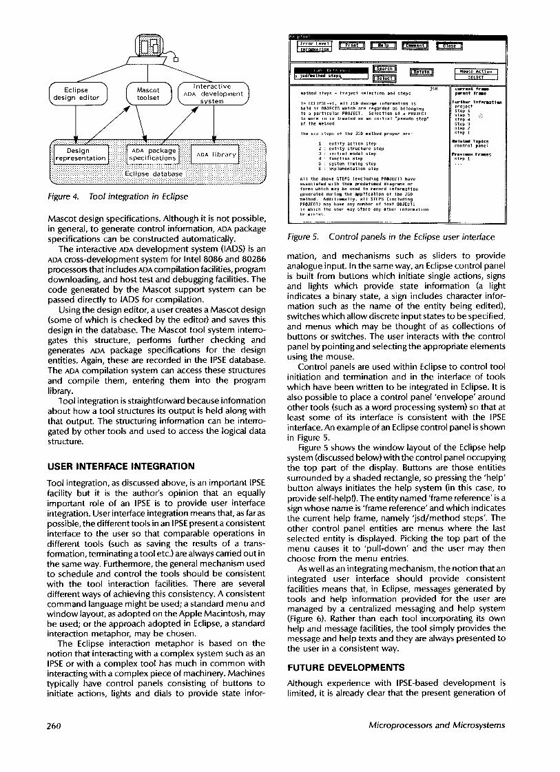
Figure 5. Control panels in the Eclipse user interface
mation, and mechanisms such as sliders to provide analogue input. In the same way, an Eclipse control panel is built from buttons which initiate single actions, signs and lights which provide state information (a light indicates a binary state, a sign includes character infor- mation such as the name of the entity being edited), switches which allow discrete input states to be specified, and menus which may be thought of as collections of buttons or switches. The user interacts with the control panel by pointing and selecting the appropriate elements using the mouse.
Control panels are used within Eclipse to control tool initiation and termination and in the interface of tools which have been written to be integrated in Eclipse. It is also possible to place a control panel 'envelope' around other tools (such as a word processing system) so that at least some of its interface is consistent with the IPSE interface. An example of an Eclipse control panel is shown in Figure 5.
Figure 5 shows the window layout of the Eclipse help system (discussed below) with the control panel occupying the top part of the display. Buttons are those entities surrounded by a shaded rectangle, so pressing the 'help' button always initiates the help system (in this case, to provide self-help!). The entity named 'frame reference' is a sign whose name is 'frame reference' and which indicates the current help frame, namely 'jsd/method steps'. The other control panel entities are menus where the last selected entity is displayed. Picking the top part of the menu causes it to 'pull-down' and the user may then choose from the menu entries.
As well as an integrating mechanism, the notion that an integrated user interface should provide consistent facilities means that, in Eclipse, messages generated by tools and help information provided for the user are managed by a centralized messaging and help system (Figure 6). Rather than each tool incorporating its own help and message facilities, the tool simply provides the message and help texts and they are always presented to the user in a consistent way.
FUTURE DEVELOPMENTS
Although experience with IPSE-based development is limited, it is already clear that the present generation of
260 Microprocessors and Microsystems
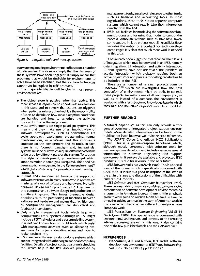
~mHelp and ~. ~User help information essage too~,~ and system messages J ' t
Help frame l Help frame' Help frame ]Help frame texts texts texts [. texts
Messages Messages Messages L Messages
I I I I ~Design ~ ~ Mascot ~ ~ ADA 1 [~onfiguration ~
editor toolset system [management I k,~ system j ' Figure 6. Integrated help and message system
software engineering environments suffers from a number of deficiencies. This does not imply that the designers of these systems have been negligent. It simply means that problems that would be desirable for environments to solve have been identified, but the solution technology cannot yet be applied in IPSE products.
The major identifiable deficiencies in most present environments are:
• The object store is passive rather than active. This means that it is impossible to encode rules and actions in this store and to specify that actions are triggered when particular rules are checked. It is the responsibility of users to decide on how most exception conditions are handled and how to schedule the activities involved in the software process.
• Most environments are single paradigm systems. This means that they make use of an implicit view of software developments, such as conventional life cycle approach, exploratory programming, formal transformations, or whatever, and this imposes a structure on the environment and its tools. In fact, there is no 'correct' paradigm and, increasingly, systems must be built which require different paradigms to be used for different parts of the system. To support this style of development, an environment which supports multiple paradigms is required. This need has been explicitly recognized in the Refine environment 16 which goes some way to providing a multiparadigm approach.
• Current IPSEs are oriented towards the support of software systems yet, in many cases, whole systems are made up of a mix of software and hardware. Typically, hardware design takes place using CAD systems on one computer and software design and production on a different system. This forces premature design decisions as to the partitioning of functions between software and hardware and means that facilities such as configuration management are duplicated and (perhaps) inconsistent.
• Only simple management tools which help with computations are supported. Although an IPSE might include a PERT scheduler and a cost modelling system, it is not yet known how to build tools which assist with management activities such as allocating pro- grammers to projects, deciding when and how to replan projects etc.
• IPSEs are currently seen as stand-alone systems which are not integrated with other organizational computing facilities. Details of project costs, personnel schedules etc., which help in the IPSE and are processed by
management tools, are also of relevance to other tools, such as financial and accounting tools. In most organizations, these tools run on separate computer systems which cannot readily take their information directly from the IPSE.
• I PSEs lack facilities for modelling the software develop- ment process and for using that model to control the process. Although systems such as Istar have taken some steps to include process modelling facilities (Istar includes the notion of a contract for each develop- ment stage), it is clear that much more work is needed in this area.
It has already been suggested that there are three levels of integration which may be provided in an IPSE, namely data integration, UI integration and activity integration. Current systems have not addressed the problem of activity integration which probably requires both an active object store and process modelling capabilities to be included in the IPSE.
There are a number of research projects currently underway 17'18 which are investigating how the next generation of environments might be built. In general, these projects are making use of AI techniques and, as well as or instead of a database, the environment is equipped with a less structured knowledge base in which facts, rules and (sometimes) a process model is embedded.
FURTHER READING
A tutorial paper such as this can only provide a very general overview of integrated project support environ- ments. More detailed information can be found in the publications listed below as well as in the cited references.
The STARTS Guide 2nd edition NCC Publications (1987). This is a general-purpose handbook which, although mostly concerned with software tools for realtime systems development, includes valuable general information on software engineering and support environments. It surveys the available and projected IPSE products. It is due for revision in the near future.
IEEE Software Vol 5 No 2 (March 1988). This is a special issue of the journal which is specifically concerned with CASE tools. It includes a good description of the state of the art in this area and discussions of the difficulties with current CASE toolsets.
IEEE Software and IEEE Computer (November 1987). These two readable journals are combined to make a joint presentation on software development environments. As is common in American journals, there is little emphasis given to work going on outside North America. In essence then, the articles summarize the state of American work in this area which has a rather different orientation from European work.
IEEE Transactions on Software Engineering Vol SE-14 No 6 (June 1988). This special issue is concerned with environmental architectures and presents some interesting articles discussing research in this area. It also contains one of the few published articles on the CAIS interface.
REFERENCES 1 Habermann, A N and Notkin, D 'Gandalf: software
development environments' IEEE Trans. Software En D Vol SE-12 No 12 (1986) pp 1117-1127
Vol 13 No 4 May 1989 261
2 Dowson, M 'Integrated project support with ISTAR' IEEE Software Vol 4 No 6 (1987) pp 6-15
3 Higgs, M and Stevens, P'Developing an environment manager for an I PSE' in Sommerville, I (ed.) Software engineering environments Peter Pedgrinus, Stevenage, U K (I 986)
4 Boil, M F (ed.) The eclipse integrated project support environment Peter Perigrinus, Stevenage, UK (1989)
5 Sellars, P W 'IPSEs in commercial data processing' in McDermid, J (ed.) Integrated project support environments Peter Perigrinus, Stevenage, UK (1985)
6 Lempp, P 'Development and project management support with the integrated software engineering environment, EPOS' in Sommerville, I (ed.) Software Engineering Environments Peter Perigrinus, Stevenage, U K (1986)
7 Simpson, H 'The MASCOT method' BCS/IEE Soft- ware En D J. Vol 1 No 3 (1986) pp 103-120
8 Gomaa, H 'A software design method for real-time systems' Comm. ACM Vo129 No 7 (1984) pp 938-949
9 Shneiderman, B Designing the user interface Addison Wesley, Reading, MA, USA (1986)
10 Buxton, J Requirements for Ada programming support environments: Stoneman US Department of Defense, Washington DC, USA (1980)
11 Oberndorf, P A'The common APSE interface set' IEEE Trans. Software Eng. Vol SE-14 No 6 (1988) pp 742-749
12 Gallo, F, Minot, R and Thomas, I 'The object management system of PCTE as a software engineering database management system' ACM Sigolan Notices Vol 22 No 1 (1987) pp 12-16
13 Scheifler, R W and Gettys, J 'The X window system' ACM Trans. Graphics Vol 5 No 2 (1986)
14 Sommerville, I, Beer, S and Welland, R C 'The Eclipse design editing system' in Proc. 1st Eur.
Software Eng. Conf. Springer-Verlag, Strasbourg, FRG (1987)
15 Sommerville, I, Welland, R C and Beer, S 'Describing software design methodologies' Comp. J. Vo130 No 2 (1987) pp 128-133
16 Smith, D R, Kotik, G B and Westfold, S J 'Research on knowledge-based software environments at Kestrel Institute' IEEE Trans. Software Eng. Vol SE-11 No 11 (1985) pp 1278-1295
17 Kaiser, G E, Feiler, P H and Popovich, S S 'Intelligent assistance for software development and main- tenance' IEEE Software Vol 5 No 3 (1988) pp 40-49
18 Ambras, J and O'Day, V 'MicroScope: a knowledge- based programming environment' IEEE Software Vol 5 No 3 (1988) pp 50-58
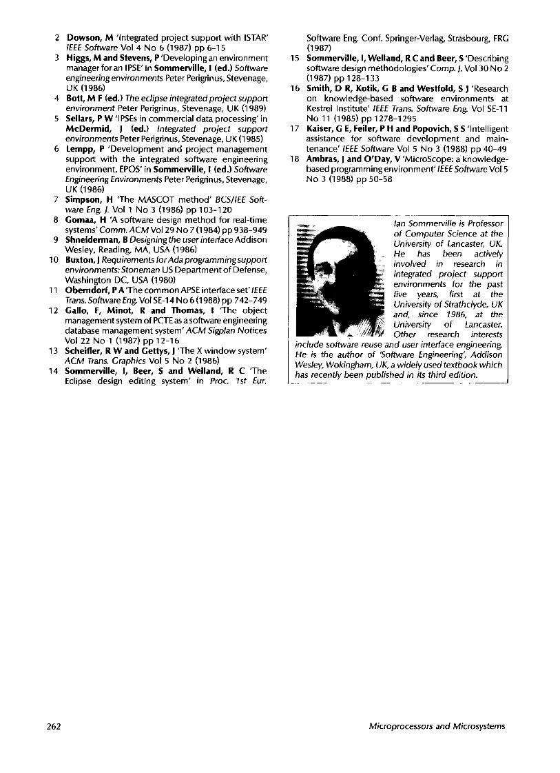
. . . . . . lan Sommerville is Professor of Computer Science at the University of Lancaster, UK. He has been actively involved in research in integrated project support environments for the past five years, first at the University of Strathclyde, UK and, since 1986, at the University of Lancaster. Other research interests
include software reuse and user interface engineering. He is the author of 'Software Engineering" Addison Wesley, Wokingham, UK, a widely used textbook which has recently been published in its third edition.
262 Microprocessors and Microsystems