Embed Size (px)
Citation preview

Integra® CUSA® ClarityUltrasonic Surgical Aspirator System
Integra® C
USA
® Clarity U
ltrasonic Surgical Aspirator System
Operator’s Manual
Operato
r’s Manual
60905197 Revision F 05/18 0606553-2
Integra LifeSciences (Ireland) LimitedIDA Business &Technology ParkSraghTullamoreCounty OffalyIreland
USA & Canada: (800) 997-4868 Outside USA: (609) 936-5400
www.integralife.com
Manufacturer

CUSA® Clarity Ultrasonic Surgical Aspirator System
Operator’s Manual


CUSA® Clarity Ultrasonic Surgical Aspirator System Operator’s Manual iii
Table of Contents
Table of ContentsPREFACE Intended Audience ...................................................................................................................... ixTrademark Acknowledgments .................................................................................................... ixManufacturer ...............................................................................................................................xPatent Information .......................................................................................................................xOverview of Manual .....................................................................................................................xSystem Features......................................................................................................................... xiIntended Uses............................................................................................................................. xiConventions Used in this Guide .................................................................................................. xi
SECTION 1 Patient and Operating Room SafetyIndications for Use ................................................................................................................... 1-1Intended Users ........................................................................................................................ 1-2Safety Information.................................................................................................................... 1-2Warnings and Cautions ............................................................................................................ 1-3
Patient and Operating Room Safety ................................................................................... 1-3Classification and Console Symbols ........................................................................................ 1-9
SECTION 2 Introduction to the SystemOverview.................................................................................................................................. 2-1CUSA® Clarity System ............................................................................................................. 2-2
Fragmentation .................................................................................................................... 2-4Irrigation ............................................................................................................................. 2-4Aspiration (Suction) ............................................................................................................ 2-5
Touchscreen Display................................................................................................................ 2-6Handpiece ............................................................................................................................... 2-6
Handpiece Functions.......................................................................................................... 2-6Handpiece Configurations .................................................................................................. 2-7Handpiece Tips................................................................................................................... 2-7
Tissue Select® Feature ............................................................................................................. 2-7Sterilization of Handpieces and Accessories...........................................................................2-11
SECTION 3 Console ComponentsOverview.................................................................................................................................. 3-1Console Features .................................................................................................................... 3-2Console – Front Panel ............................................................................................................. 3-4Console – Rear Panel .............................................................................................................. 3-5
CUSA® Clarity Ultrasonic Surgical Aspirator System Operator’s Manualiv
Table of Contents
SECTION 4 Touchscreen Display and FunctionsOverview.................................................................................................................................. 4-1Touchscreen Layout................................................................................................................. 4-1
Main Screen ....................................................................................................................... 4-2Setup Tasks Screen ............................................................................................................ 4-3Settings Screen .................................................................................................................. 4-3Online Help......................................................................................................................... 4-4
Alarm Indicators ....................................................................................................................... 4-4Ultrasonic Control Scale Adjustments ...................................................................................... 4-5
Adjusting the Ultrasonic Control Scale Values .................................................................... 4-5Footswitch and Aspiration Modes ............................................................................................ 4-6
Footswitch Mode ................................................................................................................ 4-6Aspiration Mode ................................................................................................................. 4-7
SECTION 5 Handpiece ComponentsOverview.................................................................................................................................. 5-1Components of Assembled Handpieces .................................................................................. 5-2
Handpiece .......................................................................................................................... 5-2Tip ...................................................................................................................................... 5-3Nosecone ........................................................................................................................... 5-3Flue .................................................................................................................................... 5-4
Additional Handpiece Components.......................................................................................... 5-4CUSA Quick Connect™ Cartridge and Tubing Set (Sterile) ................................................. 5-4Aspiration Tubing................................................................................................................ 5-5Irrigation Tubing.................................................................................................................. 5-5Cartridge ............................................................................................................................ 5-5Single-Use Torque Wrench (Sterile) ................................................................................... 5-5Torque Base (Sterilizable) .................................................................................................. 5-6
SECTION 6 Assembling the System Prior to UseOverview.................................................................................................................................. 6-1Assembling the Console and Cart ............................................................................................ 6-2Attaching the Power Cord ........................................................................................................ 6-3
SECTION 7 System Setup in the Sterile FieldOverview.................................................................................................................................. 7-1Quick Reference: Setting Up in the Sterile Field....................................................................... 7-2Assembling the Handpiece in the Sterile Field ......................................................................... 7-3
Attaching a Tip .................................................................................................................... 7-3Attaching the Nosecone and the Flue ................................................................................. 7-5Attaching the Tubing ........................................................................................................... 7-7
CUSA® Clarity Ultrasonic Surgical Aspirator System Operator’s Manual v
Table of Contents
SECTION 8 System Setup in the Non-Sterile FieldOverview.................................................................................................................................. 8-1Quick Reference: Setting Up in the Non-Sterile Field ............................................................... 8-1Assembling the Handpiece ...................................................................................................... 8-2Console Setup (Non-Sterile) .................................................................................................... 8-2
Powering Up the System .................................................................................................... 8-2Attaching the Footswitch .................................................................................................... 8-3Attaching the Handpiece .................................................................................................... 8-3Connecting the Tubing Set ................................................................................................. 8-4
SECTION 9 Operating the SystemOverview.................................................................................................................................. 9-1Quick Reference: Operating the System .................................................................................. 9-2Priming the System .................................................................................................................. 9-2
Start Prime ......................................................................................................................... 9-2Stop Prime.......................................................................................................................... 9-3
Testing the Handpiece ............................................................................................................. 9-4Start Test ............................................................................................................................ 9-4Detailed Test Results .......................................................................................................... 9-5System Ready for Use ........................................................................................................ 9-5
SECTION 10 Changing Tips in the Sterile Field During a Surgical ProcedureOverview................................................................................................................................ 10-1Quick Reference: Changing Tips ........................................................................................... 10-1Changing a Tip ....................................................................................................................... 10-2
Removing the Used Tip .................................................................................................... 10-2Assembling the New Tip on the Handpiece....................................................................... 10-6
SECTION 11 Disassembling, Cleaning, and Sterilizing the SystemOverview.................................................................................................................................11-1Quick Reference: Disassembling the System .........................................................................11-1Quick Reference: Cleaning the System ..................................................................................11-2Disassembling the System......................................................................................................11-2
Which CUSA® Clarity Items to Keep and Discard After a Surgical Procedure .....................11-2Disassembling the Handpiece ...........................................................................................11-2Disassembling the Console ...............................................................................................11-7Detaching the Contamination Guard ...............................................................................11-10Powering Down the System.............................................................................................11-10
Cleaning the System ............................................................................................................. 11-11Cleaning the Touchscreen ...............................................................................................11-11Cleaning the Console and Cart ........................................................................................ 11-11Cleaning the Handpiece, EUT, and Torque Base .............................................................11-12Cleaning the Footswitch ..................................................................................................11-13Sterilization Tray Cleaning ...............................................................................................11-13
CUSA® Clarity Ultrasonic Surgical Aspirator System Operator’s Manualvi
Table of Contents
Sterilizing the System ...........................................................................................................11-14Packaging the Handpiece and Components for Sterilization ...........................................11-14
Sterilization Parameters........................................................................................................11-16Sterilization Tray Packaging ............................................................................................11-16Sterilizing the Handpiece and Components with Steam ..................................................11-17
SECTION 12 Maintaining the SystemOverview................................................................................................................................ 12-1Quick Reference .................................................................................................................... 12-2Handpiece Maintenance ........................................................................................................ 12-2
Return and Replace the Handpiece .................................................................................. 12-2Handling and Transporting of the System .............................................................................. 12-3Storage of the System and Accessories ................................................................................. 12-3
Console ............................................................................................................................ 12-3Console with Cart ............................................................................................................. 12-3Handpiece ........................................................................................................................ 12-4Footswitch ........................................................................................................................ 12-4
Disposal of the Equipment ..................................................................................................... 12-4Return Equipment for Service ................................................................................................ 12-4
Obtaining a Return Authorization Number ........................................................................ 12-4Returning the Console ...................................................................................................... 12-5Returning the Handpiece .................................................................................................. 12-5Ordering Replacement Parts ............................................................................................ 12-5
Integra Service Centers ......................................................................................................... 12-6US Service Center ............................................................................................................ 12-6Europe, Middle East and Africa Service Center ................................................................ 12-6Asia Pacific Service Center .............................................................................................. 12-6
SECTION 13 Troubleshooting the SystemOverview................................................................................................................................ 13-1Extracting Log Files ............................................................................................................... 13-2Alarm Descriptions................................................................................................................. 13-2Technical Messages .............................................................................................................. 13-3Amplitude Troubleshooting .................................................................................................... 13-3Aspiration Troubleshooting .................................................................................................... 13-5Irrigation Troubleshooting ...................................................................................................... 13-5
CUSA® Clarity Ultrasonic Surgical Aspirator System Operator’s Manual vii
Table of Contents
SECTION 14 MR Safety InformationOverview................................................................................................................................ 14-1Use of the CUSA Clarity System in the MR environment ........................................................ 14-2
SECTION A Technical SpecificationsConsole ...................................................................................................................................A-1
Dimensions ........................................................................................................................A-1Tip Specifications ..................................................................................................................... A-2Subsystems .............................................................................................................................A-3Handpiece ...............................................................................................................................A-3
Dimensions ........................................................................................................................A-3Frequency ..........................................................................................................................A-3
Electrical Requirements ........................................................................................................... A-4Power Input and Fusing ...................................................................................................... A-4Power Cords....................................................................................................................... A-4Maximum Low Frequency Leakage .................................................................................... A-5
Duty Cycle ............................................................................................................................... A-5Electromagnetic Interference ............................................................................................. A-5
Environment ............................................................................................................................A-5Operating ...........................................................................................................................A-5Storage and Shipping ......................................................................................................... A-5
Voluntary Standards ................................................................................................................ A-6Statutory and Regulatory Classification .............................................................................. A-6EMC Compatibility .............................................................................................................. A-6Guidance and Manufacturer’s Declarations ....................................................................... A-7
SECTION B WarrantyWarranty ..................................................................................................................................B-1
Coverage............................................................................................................................B-1Exclusions ..........................................................................................................................B-1
Service, Repairs and Replacement.......................................................................................... B-2Service and Repairs ........................................................................................................... B-2Equipment Replacement .................................................................................................... B-2Notification .........................................................................................................................B-2
Repair Parts and Services ....................................................................................................... B-2Consoles..................................................................................................................................B-2
Handpieces ........................................................................................................................B-2Modifications to Covered Equipment .................................................................................. B-3
Quality Control ......................................................................................................................... B-3Limitations of Liability ............................................................................................................... B-3

CUSA® Clarity Ultrasonic Surgical Aspirator System Operator’s Manualviii
Table of Contents
Intentional Blank
CUSA® Clarity Ultrasonic Surgical Aspirator System Operator’s Manual ix
PREFACE
Intended Audience
Trademark Acknowledgments
This operator’s manual and the equipment it describes are for use only by qualified medical professionals trained in the particular technique and surgical procedure to be performed. It is intended as a guide for using the CUSA® Clarity Ultrasonic Surgical Aspirator System only.
Integra, the Integra logo, CUSA, and Tissue Select are registered trademarks of Integra LifeSciences Corporation or its subsidiaries in the United States and/or other countries. ShearTip, MicroTip, and CUSA Quick Connect are trademarks of Integra LifeSciences Corporation or its subsidiaries. Sani-Cloth is a trademark of Professional Disposables International, Inc. neodisher is a trademark of Chemische Fabrik Dr. Weigert GmbH & Co. KG. All other trademarks and trade names are the property of their respective owners.
CAUTIONFederal (USA) law restricts this device to sale by or on the order of a physician.

CUSA® Clarity Ultrasonic Surgical Aspirator System Operator’s Manualx
Preface
Integra LifeSciences (Ireland) Limited IDA Business & Technology Park Sragh Tullamore, County Offaly, Ireland
Integra LifeSciences Corporation Plainsboro, NJ 08536 USA; 1-800-997-4868
© 2018 Integra LifeSciences Corporation. All Rights Reserved. Contents of this publication may not be reproduced in any form without the written permission of Integra.
Manufacturer
Patent Information
Overview of Manual
U.S. Patents 6,499,358; 8,118,823; 8,518,066; 9,421,027; D796,667; D819,195; additional patent(s) pending
This operator’s manual describes how to use the CUSA Clarity Ultrasonic Surgical Aspirator System. It presents the CUSA Clarity as a system that includes a console, handpieces, and accessories. It describes:
• The system and its functions
• The console, its subsystems, and its components
• The handpiece and its components
• How to setup and use the console
• How to assemble and use the handpiece with the system
• How to disassemble the handpiece
• How to clean components of the system
• How to sterilize components of the system
CUSA® Clarity Ultrasonic Surgical Aspirator System Operator’s Manual xi
Preface
NOTEIndicates additional information.
CAUTIONIndicates a hazardous situation that, if not avoided, could result in product damage.
WARNINGIndicates a potentially hazardous situation that, if not avoided, could result in serious injury or death.
System Features
Intended Uses of this Manual
Conventions Used in this Guide
The CUSA Clarity system includes several important components and features:
• Console with touchscreen interface
• Cart
• 36 kHz handpiece
• A variety of surgical tips that attach to the handpiece:
• Sterile, single-use tips
• Non-sterile, extended use tips (EUT)
• Tissue Select® feature, which increases the selectivity of the surgical tip, allowing greater control and precision
When you receive your CUSA Clarity system, we recommend that you read and understand all of this operator’s manual before using the system. Also, use the manual for:
• Reference - When you need specific information on a task.
• Training - When training new personnel to use the system.
To draw immediate attention to matters of importance, this manual presents Warnings, Cautions, and Notes

CUSA® Clarity Ultrasonic Surgical Aspirator System Operator’s Manualxii
Preface
Intentional Blank
Patient and Operating Room SafetySECTION 1
Indications for Use
In this section:
• Indications for Use, page 1-1
• Contraindications, page 1-2
• Safety Information, page 1-2
• Warnings and Cautions, page 1-3
• Classification and Console Symbols, page 1-9
The CUSA® Clarity Ultrasonic Surgical Aspirator System is indicated for use in surgical procedures where fragmentation, emulsification and aspiration of soft tissue is desirable.
The CUSA Clarity Ultrasonic Surgical Aspirator is indicated for use in:
• Neurosurgery, Plastic and Reconstructive surgery, Orthopedic Surgery, Gynecological Surgery and Thoracic Surgery and the following specific uses:
• Gastrointestinal and Affiliated Organ Surgery - including removal of benign or malignant tumors or other unwanted tissue, including hepatic parenchyma, in open or laparoscopic procedures, hepatic resection, tumor resection, lobectomy or trisegmentectomy, or removal of tissue during liver allotransplantation and donor hepatectomy.
• Urological surgery - including removal of renal parenchyma during nephrectomy or partial nephrectomy.
• General Surgery - including removal of benign or malignant tumors or other unwanted soft tissue in open or minimally invasive general surgical procedures.
• Laparoscopic Surgery - including removal of hepatic parenchyma in laparoscopic hepatic resection, lobectomy or trisegmentectomy, in laparoscopic donor hepatectomy or laparoscopic cholecystectomy or laparoscopic pancreatic jejunostomy, or pancreatectomy, or laparoscopic appendectomy, laparoscopic colon resection or laparoscopic partial gastrectomy.

CUSA® Clarity Ultrasonic Surgical Aspirator System Operator’s Manual1-2
Contraindications
Intended Users
Contraindication
Safety Information
WARNINGIt is the responsibility of the Healthcare Facility to ensure that intended users of the CUSA Clarity system are appropriately trained in the use of this equipment.
You should use the CUSA Clarity system only in a surgical environment by qualified medical professionals trained in the use of this equipment.
This system must be set up/disassembled by operating room (OR) staff (for example, surgical nurse, neuro technician). The OR staff is also likely to operate the device controls. The handpiece and footswitch are controlled by the surgeon.
The safe and effective use of ultrasonic surgery depends to a large degree on factors solely under the control of the operator. Only medical professionals that are properly trained in the use of ultrasonic equipment should operate the CUSA Clarity system. It is important that medical professionals read, understand, and follow the operating instructions supplied with this equipment.
Before starting any surgical procedure, medical professionals should be familiar with the medical literature, complications, and hazards of using ultrasonic surgery in that procedure.
This ultrasonic surgical aspirator device is not indicated for and should not be used for the fragmentation, emulsification, and aspiration of uterine fibroids.

CUSA® Clarity Ultrasonic Surgical Aspirator System Operator’s Manual 1-3
Warnings and Cautions
WARNINGThe CUSA Clarity Ultrasonic Surgical Aspirator System, including all accessories and components, is MR Unsafe. It must not be brought into the MR environment.
WARNINGOperating the CUSA Clarity system outside of the specified environmental conditions may result in injury to the patient and/or user, or equipment damage, which may result in a delay in patient treatment.
WARNINGNo modification of this equipment is allowed.
WARNINGSingle-use devices are for single patient use only. Do not reprocess or re-use.
WARNINGIgnoring alarms on the CUSA Clarity system while continuing to use the system may result in injury to the patient and/or user, or equipment damage.
WARNINGTo avoid risk of electric shock, this equipment must only be connected to a supply mains with protective earth.
Warnings and CautionsTo promote the safe use of the CUSA Clarity system, this section lists the warnings and cautions that appear throughout this operator’s manual. To operate this equipment with maximum safety, it is important to read, understand, and follow the instructions in these warning and cautions.
Patient and Operating Room Safety
CUSA® Clarity Ultrasonic Surgical Aspirator System Operator’s Manual1-4
Warnings and Cautions
WARNINGWhen the handpiece is connected to a CUSA Clarity system that is powered on, but the handpiece is not in use, keep the handpiece away from the patient. Place the handpiece on a sterile, flat, dry, nonconductive, and highly visible surface.
WARNINGWhen the handpiece is powered on, contact of the tip with a hard surface (for example: a metal instrument, tray, staples, clips, instruments, and so on) may damage the tip of the handpiece.
WARNINGDo not use a damaged handpiece with the CUSA Clarity system. This may result in injury to the patient or user.
WARNINGThe handpiece and handpiece accessories (tip, flue, stylet and nosecone) must be sterile before surgical use.
WARNINGTouching the tip of the handpiece by the user, while the handpiece is powered on, may result in personal injury.
WARNINGTo avoid injury to the user, keep fingers away from the peristaltic pump and pinch valve.
WARNINGTo avoid injury or damage to equipment, place system in standby prior to changing tip or clearing a clog.

CUSA® Clarity Ultrasonic Surgical Aspirator System Operator’s Manual 1-5
Warnings and Cautions
WARNINGPotential Burn Hazard - CUSA Clarity tips utilize a silicone flue. Compressing the flue against the side of the vibrating surface along the length of the tip may cause excessive heating, which may burn the adjacent tissue of the surgical site.
WARNINGExcessive loading of CUSA Clarity tips at the surgical site may induce heating due to vibration and acoustic power transmissions. Thermal management of the surgical site with the aid of the appropriate irrigation and aspiration settings is essential.
WARNINGIf the aspiration tubing and contamination guard are not connected to the correct canister ports, the system may not work.
WARNINGAvoid excessive lateral loading of CUSA Clarity tips. This may result in injury to the patient and/or user, or equipment damage.
WARNINGAvoid contacting bone with the CUSA Clarity tips.
WARNINGDo not use the sterile torque wrench for more than one surgical procedure. Reprocessing may damage the torque wrench.
WARNINGBefore use, sterilize the torque base in the sterilization tray with the handpiece.

CUSA® Clarity Ultrasonic Surgical Aspirator System Operator’s Manual1-6
Warnings and Cautions
WARNINGExplosion Hazard - Do not use the CUSA Clarity system in the presence of flammable anesthetics or other volatile solvents.
WARNINGElectric Shock Hazard - Always unplug the CUSA Clarity system before cleaning it.
WARNINGElectrical Shock Hazard - Do not remove cover. Refer servicing to authorized service personnel.
WARNINGThe minimum aspiration level setting is 10%. This ensures proper handpiece cooling and performance. Insufficient aspiration may cause premature handpiece or tip failures and may induce heat exchange with the patient or user, and cause tissue burns.
WARNINGFor continued protection against fire and electrical hazard, replace fuse only with same type and rating. Refer to “Power Input and Fusing” on page A-4.
WARNINGWhen testing the handpiece, do not allow the tip to come in contact with any person or object during tip activation. Contact may result in injury to the patient and/or user, or handpiece tip damage.
Contact with any object or person may cause the test to fail.
WARNINGDo not allow fluids to enter the console.
WARNINGDo not power up the handpiece without performing a prime cycle (that is, irrigation fluid must flow from the distal tip of the handpiece). Failure to prime the handpiece could result in permanent damage to the handpiece (internal and/or external components) and may induce heat exchange with the patient and/or user, and cause tissue burns.

CUSA® Clarity Ultrasonic Surgical Aspirator System Operator’s Manual 1-7
Warnings and Cautions
WARNINGIf the packaging for a sterile accessory is damaged, do not use the sterile accessory.
WARNINGTo ensure sterility, assemble sterile handpiece and tip in the sterile field only.
CAUTIONRead the instructions, warnings, cautions, and notes provided with the CUSA Clarity system before use; otherwise, injury to the patient and/or user, or equipment damage may result.
CAUTIONDuring surgery, under maximum loading conditions, CUSA Clarity system has an ultrasonic duty cycle of 10 minutes on, 5 minutes off.
CAUTIONBefore surgery, apply the brake locks to all wheels on the cart (if using the optional Integra cart) to stop the wheels from rolling.
CAUTIONWhen using the console without a cart, prior to surgery, place the console on a solid surface. The surface must be flat, non-slip, and free from obstruction.

CUSA® Clarity Ultrasonic Surgical Aspirator System Operator’s Manual1-8
Warnings and Cautions
CAUTIONTo avoid product damage, always use the torque base to hold the handpiece while using the torque wrench to tighten or loosen the tip. Avoid over torqueing the tip.
CAUTIONHigh frequency surgical equipment can affect the function of medical electrical devices such as ultrasonic aspirators. When using monopolar high frequency surgical equipment simultaneously with the CUSA Clarity system, contact between the activated monopolar electrosurgery instrument and the CUSA Clarity surgical tip could affect system functionality. Avoid contact between the CUSA Clarity surgical tip and an activated monopolar surgical instrument.
CAUTIONProduct damage may result if you do not follow the instructions described in the cleaning section.
CAUTIONDo not use sterilization methods involving temperatures in excess of 134ºC as this may damage the handpiece.
CAUTIONTo move the console up or down a ramp, use two or more people.

CUSA® Clarity Ultrasonic Surgical Aspirator System Operator’s Manual 1-9
Classification and Console Symbols
Classification and Console SymbolsSymbol Description
Follow Instructions for Use
MR Unsafe
This equipment meets type Cardiac Floating (CF) safety standards
High Voltage Warning
Ground Stud Marking
System Power On/Off
Handpiece Connector
Footswitch Connector
Catalogue Number
Serial Number
Date of Manufacture
Manufacturer
Amplitude Pedal
Fast Flush Pedal
Dispose in accordance with WEEE regulations
CUSA® Clarity Ultrasonic Surgical Aspirator System Operator’s Manual1-10
Classification and Console Symbols
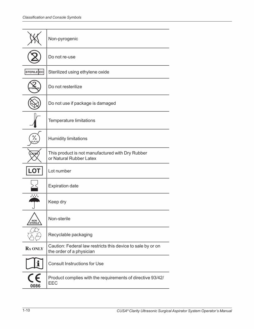
Non-pyrogenic
Do not re-use
Sterilized using ethylene oxide
Do not resterilize
Do not use if package is damaged
Temperature limitations
Humidity limitations
This product is not manufactured with Dry Rubber or Natural Rubber Latex
Lot number
Expiration date
Keep dry
Non-sterile
Recyclable packaging
Caution: Federal law restricts this device to sale by or on the order of a physician
Consult Instructions for Use
Product complies with the requirements of directive 93/42/EEC
Introduction to the SystemSECTION 2
Overview
In this section:
• Overview, page 2-1
• CUSA® Clarity System, page 2-2
• Handpiece, page 2-6
• Tissue Select® Feature, page 2-7
• Sterilization of Handpieces and Accessories, page 2-11
CAUTIONRead the instructions, warnings, cautions, and notices provided with the CUSA® Clarity system before use. Otherwise, injury to the patient or user or equipment damage may result.
This section provides general information about the CUSA Clarity Ultrasonic Surgical Aspirator System: what it is, what it does, and how it works. It also describes the handpiece functions, configurations, and the sterilization requirements for the handpiece and accessories.
CUSA® Clarity Ultrasonic Surgical Aspirator System Operator’s Manual2-2
CUSA Clarity System
NOTEAll three functions may occur at the same time.
CUSA Clarity System
The CUSA Clarity system is an ultrasonic surgical aspirator system that allows a surgeon to remove tissue efficiently and selectively. It performs three functions:
• Fragmentation: When the vibrating tip of the handpiece comes into contact with the tissue, the cells of the tissue break apart or “fragment”.
• Irrigation: Irrigation fluid from a user-supplied saline bag or Lactated Ringer’s solution is transferred to the distal tip of the handpiece.
• Aspiration (Suction): Draws or “aspirates” irrigation fluid, fragmented tissue, and other material through the distal end of the surgical tip to the user-supplied canister.

CUSA® Clarity Ultrasonic Surgical Aspirator System Operator’s Manual 2-3
The system includes the following items:
Components:
• Console: houses electronics, pumps, and mechanical parts. It includes a touch screen that allows you to control the functions of the system.
• Cart: provides a secure platform for the console. It has a handle and locking casters to facilitate movement and provide storage for the footswitch and power cord.
• Handpiece: a hand-held surgical device with a tip that is applied to patient tissue.
• Footswitch: a device connected to the console that includes two pedals used to control the ultrasonic power and irrigation fluid.
• Torque Base: a device that holds the handpiece to tighten or loosen a tip with the torque wrench.
• Contamination Guard: the filter and tubing that connects between the canister and the console. This assembly filters any remaining particulate matter or moisture, preventing them from entering the vacuum pump.
• Sterilization Tray: a tray for steam sterilizing the handpiece (including the cable and connector), tip pack components, and torque base.
• Canister: a container that stores the used irrigation fluid, fragmented tissue, and other aspirated materials. (User Supplied)
• Irrigations Fluid Bag: can be saline or Lactated Ringer’s solution (User supplied)
CUSA Clarity System

CUSA® Clarity Ultrasonic Surgical Aspirator System Operator’s Manual2-4
CUSA Clarity System
• Accessories:
• CUSA Quick Connect™ Cartridge and Tubing Set: the sterile tubing and cartridge kit includes the aspiration tubing (aspirates away used irrigation fluid, fragmented tissue, and other materials to the canister), irrigation tubing (provides irrigation to the surgical site during the surgical procedure), and a cartridge (connects the tubing to the console). The kit is designed for single patient use and must be disposed of after surgery.
• Single Use Tip Pack: the single-use tip pack contains a tip, flue, nosecone, and stylet. The stylet is used to remove tissue blockage from the tip and/or handpiece. You can remove the stylet from the packaging and put it aside within the sterile field for later use. The pack is designed for single patient use and must be disposed of after each surgery.
• Extended Use Tip (EUT) Pack: the EUT pack contains a single tip, five nosecones, five flues, and five stylets. The tip must be sterilized and may be used up to five times. Each nosecone, flue, and stylet must be sterilized before use and must be disposed of after each use.
• Torque Wrench: the torque wrench is designed for single-use and must be disposed of after each surgery.
• Specimen Trap: a device that attaches to the canister to trap waste.
• Cleaning Brush: a brush that is used to clean the internal pathway of the handpiece and tip.
Fragmentation
Electromechanical Operation
The console supplies the high-frequency handpiece with an alternating voltage signal at 36,000 cycles per second (36 kHz). This voltage is directed to opposite poles of a stack of piezoelectric ceramic discs, which are fastened to the metallic body inside the handpiece. The resulting oscillating electric field causes the discs to vibrate, and this vibration is transmitted down the length of the metallic body and into the surgical tip. The slender, tapered shape of the surgical tip focuses this vibrational energy, causing tissue fragmentation.
IrrigationThe system transfers irrigation fluid from a user-supplied IV saline or Lactated Ringer’s solution to the distal tip of the handpiece. Sterile irrigation fluid flows from an IV set (bottle or bag and IV administration tubing) to a variable speed peristaltic pump.

CUSA® Clarity Ultrasonic Surgical Aspirator System Operator’s Manual 2-5
CUSA Clarity System
The pump:
• Moves fluid at 2 to 20 mL/min; default flow is 3 mL/min. Use the adjustment slider (move the slider up/down on the Irrigation column on the touch screen) to increase or decrease the irrigation flow in 1 mL/min increments.
• Accelerates to a Fast Flush speed, pumping at 25 mL/min ± 0.5 mL/min. The Fast Flush pedal on the system footswitch activates the Fast Flush feature.
The pump pushes the fluid through the manifold irrigation tubing to a flue, a sleeve surrounding the vibrating tip. As the irrigation fluid passes through the flue, it cools the tip.
When the fluid reaches the distal end of the tip, as much as 99% of it passes through two pre-aspiration holes in the tip, preventing fluid pooling in the sterile field and continually clearing the suction system. Fluid that does not pass through the pre-aspiration holes irrigates the surgical site and suspends fragmented tissue.
Aspiration (Suction)
Aspiration enables Constant Tissue Contact, the consistent, tangible contact between tip and tissue which is essential in efficient tissue resection.
A vacuum pump in the console provides nominally 640 mmHg maximum dead head vacuum at sea level. Use the adjustment buttons (move the slider up/down on the Aspiration column on the touchscreen display) to increase or decrease the suction from 10 to 100% in 5% increments; default is 60%.
The suction, which produces an air stream moving toward the vacuum pump, pulls irrigation fluid, fragmented tissue, and other materials through the distal end of the surgical tip. From the tip, the aspirated materials pass through the handpiece and manifold suction tubing into the suction canister. From the suction canister, the air stream continues to flow through a contamination guard that filters any remaining particulate matter or moisture, preventing them from entering the vacuum pump.
The accuracy of the vacuum level in the aspiration tubing at the port of the handpiece is ± 66 mmHg and never less than 30 mmHg.
A suction pinch valve on the front of the console opens when the system is on, and closes to stop suction when:
• Priming the irrigation system
• Pressing the Fast Flush pedal
• Releasing the amplitude pedal in Run Status (in this case, the pinch valve closes for approximately one second, then re-opens).
• Releasing the amplitude pedal in the on demand aspiration mode (this suction stoppage prevents depletion of the pneumoperitoneum).
When the system is powered off, the suction pump remains off and the suction pinch valve remains closed. Use the pinch value button on the front of the suction pinch valve to open the valve manually.
CUSA® Clarity Ultrasonic Surgical Aspirator System Operator’s Manual2-6
Touchscreen Display
Touchscreen Display
Handpiece
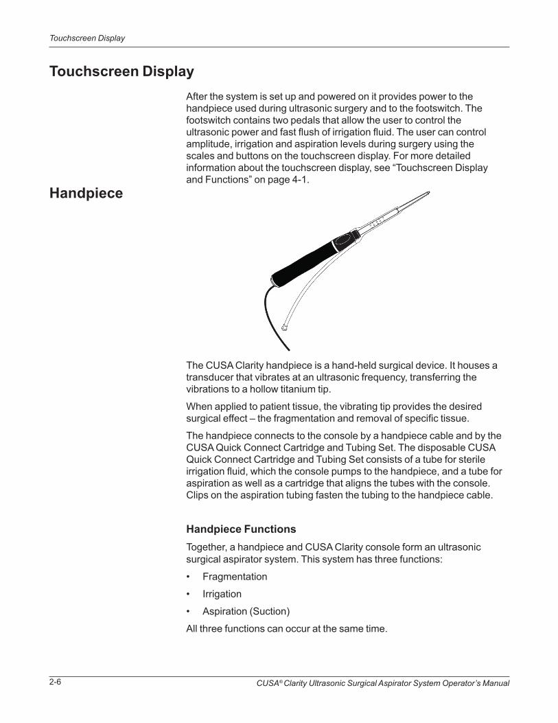
After the system is set up and powered on it provides power to the handpiece used during ultrasonic surgery and to the footswitch. The footswitch contains two pedals that allow the user to control the ultrasonic power and fast flush of irrigation fluid. The user can control amplitude, irrigation and aspiration levels during surgery using the scales and buttons on the touchscreen display. For more detailed information about the touchscreen display, see “Touchscreen Display and Functions” on page 4-1.
The CUSA Clarity handpiece is a hand-held surgical device. It houses a transducer that vibrates at an ultrasonic frequency, transferring the vibrations to a hollow titanium tip.
When applied to patient tissue, the vibrating tip provides the desired surgical effect – the fragmentation and removal of specific tissue.
The handpiece connects to the console by a handpiece cable and by the CUSA Quick Connect Cartridge and Tubing Set. The disposable CUSA Quick Connect Cartridge and Tubing Set consists of a tube for sterile irrigation fluid, which the console pumps to the handpiece, and a tube for aspiration as well as a cartridge that aligns the tubes with the console. Clips on the aspiration tubing fasten the tubing to the handpiece cable.
Handpiece FunctionsTogether, a handpiece and CUSA Clarity console form an ultrasonic surgical aspirator system. This system has three functions:
• Fragmentation
• Irrigation
• Aspiration (Suction)
All three functions can occur at the same time.

CUSA® Clarity Ultrasonic Surgical Aspirator System Operator’s Manual 2-7
Tissue Select Feature
NOTEThe high frequency handpiece operates within a frequency range and 36 kHz is a representative value. See the “Technical Specifications” on page A-3 for the frequency range.
Handpiece ConfigurationsThe CUSA Clarity system includes a high frequency handpiece.
Handpiece TipsA variety of handpiece tips are available.Tips vary in internal diameter and length. For information on the tips available, see “Tip Specifications” on page A-2.
Tissue Select® FeatureThe Tissue Select® feature allows the surgeon to maintain a high fragmentation rate while increasing selectivity and control at the surgical site.
The benefits of Tissue Select are:
• Gives surgeon greater control and precision when resecting near critical structures
• Enhances tissue selectivity while maintaining fragmentation capability. The power to the site is limited while strength and efficacy in tissue removal are still provided.
• Provides maximum tissue selectivity
• Gives surgeon superior tactile feedback
FragmentationFragmentation occurs when the vibrating tip comes into contact with tissue. As the tip begins to move toward tissue, it accelerates, then impacts and penetrates the tissue. The acceleration, impact, and penetration produce a combination of direct mechanical forces and hydrodynamic pressures that burst cells.
Several variables affect the fragmentation rate. Most are functions of the CUSA Clarity system:
• Amplitude (tip excursion—the total distance the tip travels): greater amplitude results in greater fragmentation rate
• Aspiration has several functions:
CUSA® Clarity Ultrasonic Surgical Aspirator System Operator’s Manual2-8
Tissue Select Feature
• It draws tissue toward the vibrating tip and creates constant tissue contact.
• It removes irrigation and fragmentation debris from the surgical site.
• If there is no suction or low suction, tissue contact does not occur, resulting in minimal tissue fragmentation and increased tissue temperature.
• Tip acceleration: produces the peak forces and pressures that fragment tissue.
• Tip cross-sectional area at the tip-tissue contact site
These variables also affect tactile feedback, what the surgeon’s hand feels when using the handpiece.
Inherent Tissue SelectivityWith all other variables remaining constant, the tip does not fragment all tissue types equally effectively. Another variable, tissue strength, affects fragmentation rate.
• “Low strength” soft tissues that are easiest to fragment include the brain and most organs. Older, partially dried tissues are also easy to fragment. “High strength” strong tissues that are most difficult to fragment include vessel structures, tendons, ligaments, healthy skin, and organ capsules.
• Strength increases and fragmentation rate decreases with tissue containing greater collagen, elastin, or both (collagen type, quantity, and organization affect cell structural quality).
Tissue strength also affects tactile feedback. The surgeon can feel a difference between the tip contacting low strength tissue and the tip contacting high strength tissue. As the tip works through low strength tissue, the surgeon feels a smooth, rhythmic sensation from the handpiece. When the tip contacts high strength tissue, it feels like it is “bouncing off” the tissue. Also, the smooth, rhythmic sensation becomes rougher. To avoid fragmenting high strength tissue, the surgeon must apply less pressure to the tip or move the tip away from the tissue. To continue fragmenting high strength tissue, the surgeon must manually apply more pressure.
Continued manual pressure on the footswitch pedals could result in unintentional damage to critical structures. Using the Tissue Select feature, the CUSA Clarity system can help the surgeon avoid these problems when dissecting near critical structures.
Increasing Tissue SelectivityIt is possible to increase the inherent selectivity resulting from variations in tissue strength while maintaining amplitude, tip acceleration, and suction. This increase in selectivity results from reducing the adaptive power that drives the tip. Remember: The ultrasonic generator delivers

CUSA® Clarity Ultrasonic Surgical Aspirator System Operator’s Manual 2-9
Tissue Select Feature
electrical power (which is directly related to the acoustic power present at the tip, which results in fragmentation) to the handpiece. Consider the power delivered to the handpiece in three terms:
• Initial power: the quantity of power necessary to drive the tip vibration in air; that is, no contact with tissue
• Adaptive power: the power necessary to maintain tip vibration under load (in contact with tissue). When the tip encounters load, a feedback loop in the system senses the additional load and provides additional power to maintain tip vibration.
• Maximum power: the greatest power output the console can provide. Maximum power is the sum of initial and adaptive power.
A Common Misunderstanding of the Amplitude Setting
It has been common practice to decrease the amplitude setting when encountering critical structures. The reasoning behind this practice is that the lower amplitude setting results in slower fragmentation rate and greater selectivity, thus greater control to help avoid damage when dissecting near the critical structures. Consider this reasoning more carefully:
• True: Decreasing the amplitude setting also decreases the fragmentation rate.
• True: Because the fragmentation rate is slower, the surgeon has a little more time to move the tip away from a critical structure before damaging it; therefore, the surgeon seems to have greater selectivity and control.
• False: The surgeon gains greater selectivity, thus greater control and precision, when dissecting near critical structures.
Why does the decrease in amplitude not give greater selectivity and control? Decreasing the amplitude does not greatly affect the adaptive power.
Decreasing the amplitude leaves plenty of adaptive power.
When the tip contacts critical structures, it still has more than enough power to fragment them if the surgeon applies pressure or prolongs the tip-tissue contact. Therefore, decreasing the amplitude setting gives the following results:
• Reduced fragmentation ability• Reduced fragmentation rate• Little increase in selectivity• Little reduction in adaptive power
CUSA® Clarity Ultrasonic Surgical Aspirator System Operator’s Manual2-10
Tissue Select Feature
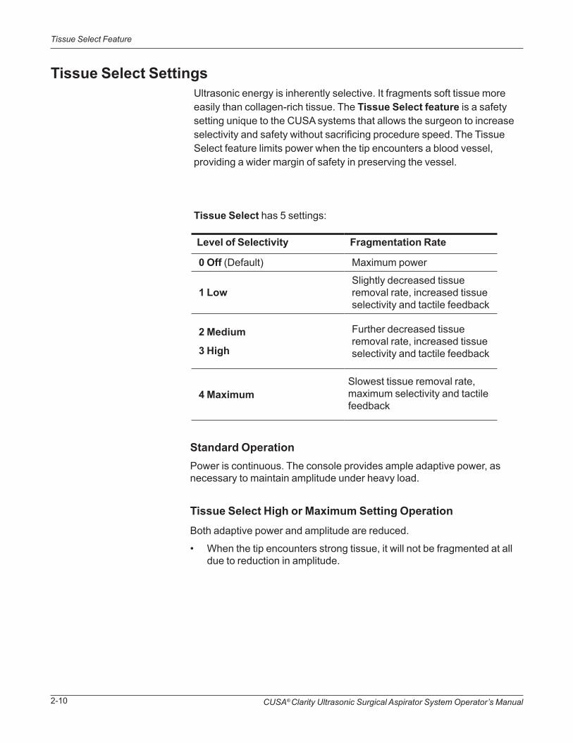
Tissue Select SettingsUltrasonic energy is inherently selective. It fragments soft tissue more easily than collagen-rich tissue. The Tissue Select feature is a safety setting unique to the CUSA systems that allows the surgeon to increase selectivity and safety without sacrificing procedure speed. The Tissue Select feature limits power when the tip encounters a blood vessel, providing a wider margin of safety in preserving the vessel.
Tissue Select has 5 settings:
Level of Selectivity Fragmentation Rate
0 Off (Default) Maximum power
1 LowSlightly decreased tissue removal rate, increased tissue selectivity and tactile feedback
2 Medium
3 High
Further decreased tissue removal rate, increased tissue selectivity and tactile feedback
4 MaximumSlowest tissue removal rate, maximum selectivity and tactile feedback
Standard OperationPower is continuous. The console provides ample adaptive power, as necessary to maintain amplitude under heavy load.
Tissue Select High or Maximum Setting OperationBoth adaptive power and amplitude are reduced.
• When the tip encounters strong tissue, it will not be fragmented at all due to reduction in amplitude.
CUSA® Clarity Ultrasonic Surgical Aspirator System Operator’s Manual 2-11
Sterilization of Handpieces and Accessories
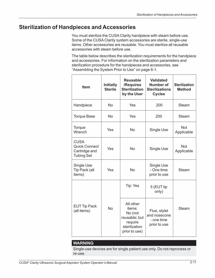
Sterilization of Handpieces and AccessoriesYou must sterilize the CUSA Clarity handpiece with steam before use. Some of the CUSA Clarity system accessories are sterile, single-use items. Other accessories are reusable. You must sterilize all reusable accessories with steam before use.
The table below describes the sterilization requirements for the handpiece and accessories. For information on the sterilization parameters and sterilization procedure for the handpieces and accessories, see “Assembling the System Prior to Use” on page 6-1.
Item InitiallySterile
Reusable/Requires
Sterilizationby the User
ValidatedNumber of
Sterilizations Cycles
SterilizationMethod
Handpiece No Yes 200 Steam
Torque Base No Yes 200 Steam
Torque Wrench Yes No Single Use Not
Applicable
CUSA Quick Connect Cartridge and Tubing Set
Yes No Single Use Not Applicable
Single Use Tip Pack (all items)
Yes NoSingle Use - One time prior to use
Steam
EUT Tip Pack (all items) No
Tip: Yes 5 (EUT tip only)
SteamAll other items:
No (not reusable; but
require sterilization prior to use)
Flue, stylet and nosecone
- one time prior to use
WARNINGSingle-use devices are for single patient use only. Do not reprocess orre-use.

CUSA® Clarity Ultrasonic Surgical Aspirator System Operator’s Manual2-12
Sterilization of Handpieces and Accessories
Intentional Blank

Console ComponentsSECTION 3
Overview
In this section:
• Overview, page 3-1
• Console Features, page 3-2
• Console – Front Panel, page 3-4
• Console – Rear Panel, page 3-5
This section describes the console for the CUSA® Clarity Ultrasonic Surgical Aspirator System. It provides an overview of the console and a description of each major console subsystem and its components.

CUSA® Clarity Ultrasonic Surgical Aspirator System Operator’s Manual3-2
Console Features
Console FeaturesThe figure illustrates the console on the optional cart. The components are described in the table.
➀
➁
➂
➃
➄
➅

CUSA® Clarity Ultrasonic Surgical Aspirator System Operator’s Manual 3-3
Console Features
Component Description
➀ Console Body
Houses the electronics, pumps, and mechanical parts. It includes a touchscreen that allows you to control the functions of the system.
➁ Handpiece Connector Connector to plug in the surgical handpiece.
➂ Contamination Guard
The filter and tubing that connects between the canister and the console. This assembly filters any remaining particulate matter or moisture, preventing them from entering the vacuum pump.
➃ Canister Holder Holder for user-supplied aspiration canister.
➄ AC Mains Connector and CableCable that plugs into a wall receptacle to provide power to the system.
➅ Footswitch
A device connected to the console that includes two pedals used to control the amplitude and irrigation fluid.
CUSA® Clarity Ultrasonic Surgical Aspirator System Operator’s Manual3-4
Console – Front Panel
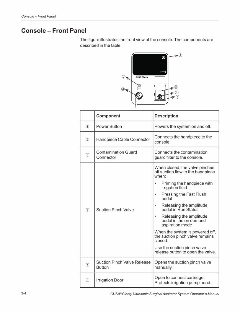
Console – Front PanelThe figure illustrates the front view of the console. The components are described in the table.
Component Description
➀ Power Button Powers the system on and off.
➁ Handpiece Cable Connector Connects the handpiece to the console.
➂Contamination Guard Connector
Connects the contamination guard filter to the console.
➃ Suction Pinch Valve
When closed, the valve pinches off suction flow to the handpiece when:• Priming the handpiece with
irrigation fluid• Pressing the Fast Flush
pedal• Releasing the amplitude
pedal in Run Status• Releasing the amplitude
pedal in the on demand aspiration mode
When the system is powered off, the suction pinch valve remains closed. Use the suction pinch valve release button to open the valve.
➄Suction Pinch Valve Release Button
Opens the suction pinch valve manually.
➅ Irrigation Door Open to connect cartridge. Protects irrigation pump head.
➀
➁
➂➃➄
➅
CUSA® Clarity Ultrasonic Surgical Aspirator System Operator’s Manual 3-5
Console – Rear Panel
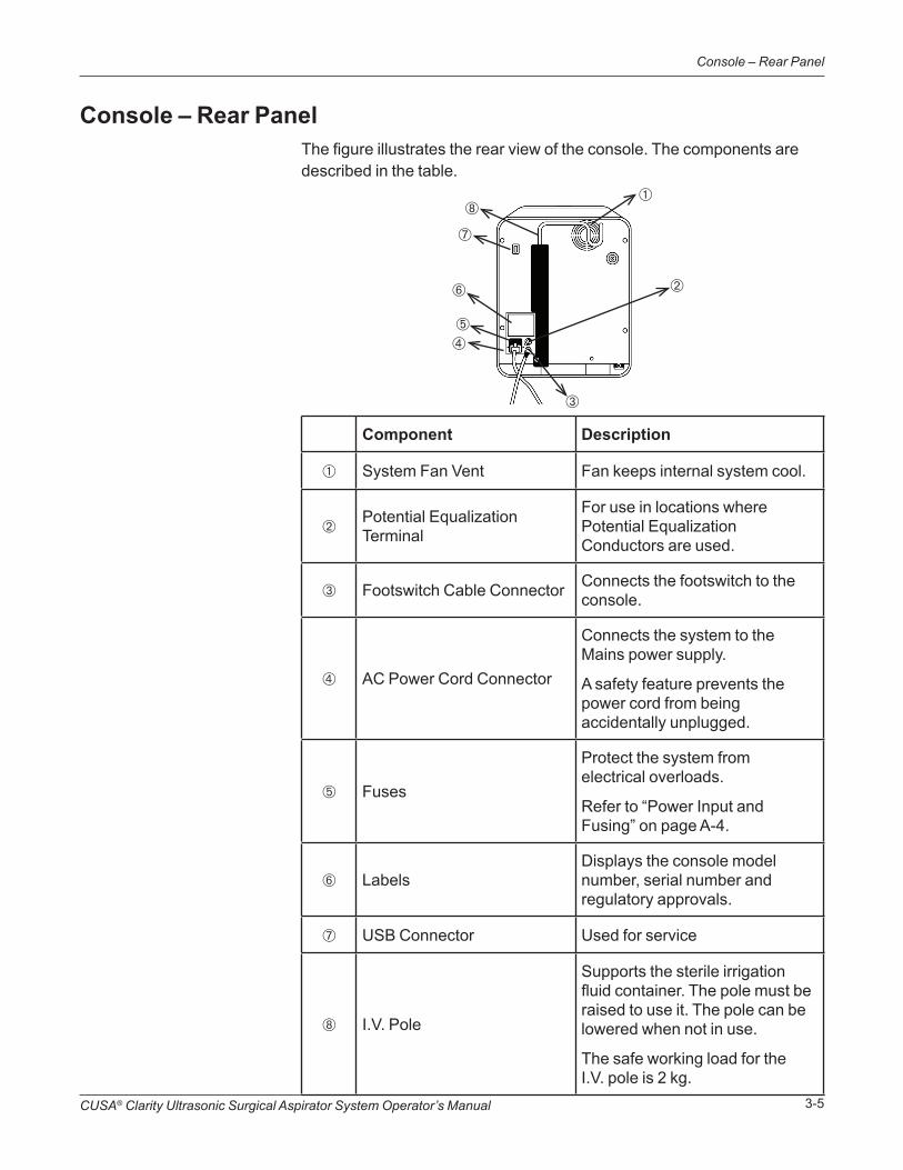
Console – Rear PanelThe figure illustrates the rear view of the console. The components are described in the table.
Component Description
➀ System Fan Vent Fan keeps internal system cool.
➁Potential Equalization Terminal
For use in locations where Potential Equalization Conductors are used.
➂ Footswitch Cable Connector Connects the footswitch to the console.
➃ AC Power Cord Connector
Connects the system to the Mains power supply.
A safety feature prevents the power cord from being accidentally unplugged.
➄ Fuses
Protect the system from electrical overloads.
Refer to “Power Input and Fusing” on page A-4.
➅ LabelsDisplays the console model number, serial number and regulatory approvals.
➆ USB Connector Used for service
➇ I.V. Pole
Supports the sterile irrigation fluid container. The pole must be raised to use it. The pole can be lowered when not in use.
The safe working load for the I.V. pole is 2 kg.
➀
➁
➂
➃➄
➅
➆
➇

CUSA® Clarity Ultrasonic Surgical Aspirator System Operator’s Manual3-6
Console – Rear Panel
Intentional Blank

Touchscreen Display and Functions
SECTION 4
Overview
Touchscreen Layout
In this section:
• Overview, page 4-1
• Touchscreen Layout, page 4-1
• Alarm Indicators, page 4-4
• Ultrasonic Control Scale Adjustments, page 4-5
• Footswitch and Aspiration Modes, page 4-6
This section describes the touchscreen display (or “touchscreen”) layout and the behavior during system startup and operation of the CUSA®
Clarity System.
The touchscreen consists of the following screens:
• Main
• Setup Tasks
• Settings
• Online Help

CUSA® Clarity Ultrasonic Surgical Aspirator System Operator’s Manual4-2
Touchscreen Layout
Main ScreenTo access the Main Screen, press the Main Screen button from any other screen.
The Main Screen contains ultrasonic control scales for amplitude, Tissue Select® , aspiration, and irrigation, slide buttons for the footswitch and aspiration modes, and buttons to open the setup tasks, settings, and online Help screens.
➀ ➁ ➂ ➃
➄
➅➆➇
➈
➀Amplitude Control Scale (see page 4-5) ➅
Online Help Button (see page 4-4)
➁Tissue Select Control Scale (see page 4-5) ➆
Settings Button (see page 4-3)
➂Aspiration Control Scale (see page 4-5) ➇
Setup / Standby Button (see page 4-3)
➃Irrigation Control Scale (see page 4-5) ➈
Footswitch Mode Slide Button (see page 4-6)
➄Aspiration Mode Slide Button (see page 4-7)

CUSA® Clarity Ultrasonic Surgical Aspirator System Operator’s Manual 4-3
Touchscreen Layout
Setup Tasks ScreenTo access the Setup Tasks screen, press the Setup/Standby button on the Main Screen. The Setup Tasks screen is displayed when the system is powered on.The Setup Tasks screen contains the setup tasks for the footswitch, handpiece, and cartridge, for priming the system, and for testing the handpiece. Press the help icon next to the task to access specific information about that task.
➀
➁
➂
➃
➄
➅
➀Footswitch Setup (see page 8-2) ➃
Start Prime Button (see page 10-2)
➁Handpiece Setup (see page 8-3) ➄
Start Test Button (see page 10-4)
➂Cartridge Setup (see page 8-4) ➅
Main Screen Button (see page 4-2)
Settings ScreenThe Settings screen contains:
• Language—Setting for the touchscreen language
Available languages are: English, French, Italian, German, Spanish, Dutch, Japanese, Chinese (Traditional), Chinese (Simplified), Korean, Russian, Danish, Polish, Finnish, Portuguese (Brazilian), Portuguese (European), Swedish, Norwegian, Czech, and Croatian.
• System Information—Provides the software, IB firmware, UM firmware, UC firmware, and operating system version numbers, and the device serial number. There is also a Extract Log button to download system log files for service help.
• Handpiece hours of use
This screen is accessed by the Settings button .

CUSA® Clarity Ultrasonic Surgical Aspirator System Operator’s Manual4-4
Alarm Indicators
Online HelpThe online Help screen provides basic information on setting up, operating, troubleshooting, disassembling, and cleaning.
This screen is accessed by the Online Help button .
Alarm IndicatorsThe CUSA Clarity System activates an alarm to indicate a technical problem with the system. All alarms on the CUSA Clarity System are technical, low-priority alarms, for example, mechanical or equipment-related. There are no physiological alarms on the CUSA Clarity system.
When the system activates an alarm, it:
• Displays a System Error screen with the a description of the alarm and a resolution
• Sounds a two-beep alarm tone every 20 seconds
Refer to the Alarm Descriptions section on 13-2 for information on how to clear alarms.
It is recommended that when the CUSA Clarity System is set up for surgery, make sure that the touchscreen is clearly visible to the surgeon in the event of an alarm. Remove any obstructions that may block the surgeon’s view of the touchscreen.
WARNINGIgnoring alarms on the CUSA Clarity system while continuing to use the system may result in injury to the patient and/or surgical personnel, or equipment damage.

CUSA® Clarity Ultrasonic Surgical Aspirator System Operator’s Manual 4-5
Ultrasonic Control Scale Adjustments
Ultrasonic Control Scale Adjustments
➀➀
➁
On the main screen, white ultrasonic control scale adjustment arrows ➀ and the selected values ➁ are shown for amplitude, Tissue Select, aspiration, and irrigation settings.
Adjusting the Ultrasonic Control Scale ValuesTo adjust the ultrasonic control scale values:
1. Select the ultrasonic control scale adjustment arrow.
2. Slide the arrow up to increase the value or down to decrease the value.
The selected value displays above the control scale.
When the Amplitude pedal is pressed, the amplitude scale border is highlighted and a feedback bar displays next to the Amplitude control scale to show that the handpiece is running.
When the Fast Flush pedal is pressed, the Irrigation scale border is highlighted to show Fast Flush is active.
Control Scale Values
The ultrasonic control scale values are:
• Amplitude: scale ranges from 10 to 100% in selectable increments of 5%; default value is 60%.
• Tissue Select: scale ranges from Off (0), Low (1), Medium (2), High (3) to Maximum (4); default value is Off. Maximum (4) provides maximum selectivity, not maximum power.
• Aspiration (Suction): scale ranges from 10 to 100% in selectable increments of 5%; default value is 60%.
CUSA® Clarity Ultrasonic Surgical Aspirator System Operator’s Manual4-6
Footswitch and Aspiration Modes
• Irrigation: scale ranges from 2 to 20 mL/min in selectable increments of 1 mL/min; default value is 3 mL/min.
When using the CUSA® Clarity ShearTip™ for fibrous tissue resection, Integra recommends using a minimum irrigation setting of 7mL/min. The irrigation setting should be adjusted based on the requirements of the specific procedure.
Ultrasonics Active Indicators
When ultrasonics is active:
• The border around the Amplitude Control Scale is highlighted in yellow, and:
• A yellow Amplitude Indicator bar rises to the left of the Amplitude Control Scale, which represents the actual amplitude of the tip.
• When Tissue Select is 0-Off, 1-Low, or 2-Medium, this yellow bar will be the same height as the Amplitude Control Scale adjustment arrow.
• When Tissue Select is 3-High, or 4-Maximum, this yellow bar will be slightly lower than the Amplitude Control Scale adjustment arrow, because these settings also reduce amplitude.
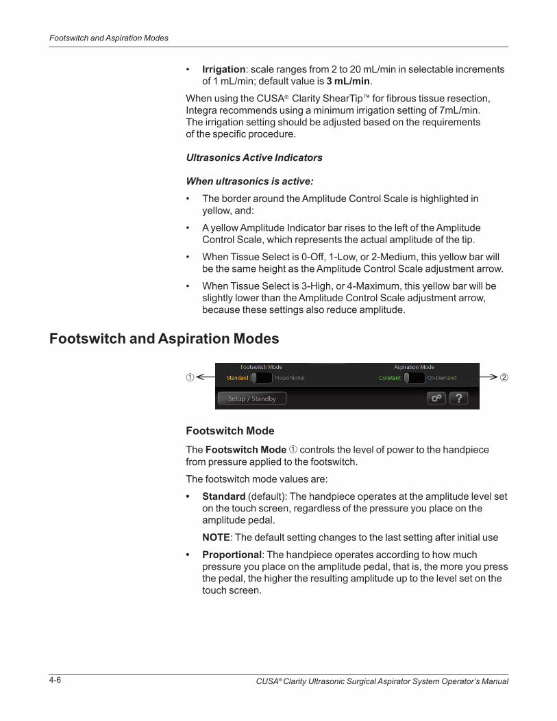
Footswitch and Aspiration Modes
Footswitch ModeThe Footswitch Mode ➀ controls the level of power to the handpiece from pressure applied to the footswitch.
The footswitch mode values are:
• Standard (default): The handpiece operates at the amplitude level set on the touch screen, regardless of the pressure you place on the amplitude pedal.
NOTE: The default setting changes to the last setting after initial use
• Proportional: The handpiece operates according to how much pressure you place on the amplitude pedal, that is, the more you press the pedal, the higher the resulting amplitude up to the level set on the touch screen.
➀ ➁
CUSA® Clarity Ultrasonic Surgical Aspirator System Operator’s Manual 4-7
Footswitch and Aspiration Modes
Aspiration ModeThe Aspiration Mode ➁ controls the flow of suction from the handpiece.
The aspiration mode values are:
• Constant (default): Constant suction and irrigation is provided to the handpiece at the level set on the touch screen.
• On Demand: Suction and irrigation is only provided to the handpiece when you activate the Amplitude pedal on the footswitch.
Selecting the Modes
To select the footswitch and/or aspiration mode, slide the Footswitch Mode (1) button and/or Aspiration Mode ➁ button right or left to the desired value.

CUSA® Clarity Ultrasonic Surgical Aspirator System Operator’s Manual4-8
Footswitch and Aspiration Modes
Intentional Blank
Handpiece ComponentsSECTION 5
Overview
In this section:
• Overview, page 5-1
• Components of Assembled Handpieces, page 5-2
• Additional Handpiece Components, page 5-4
This section describes the components of an assembled handpiece, the physical characteristics, and functions. It also describes the components needed to assemble the handpiece.

CUSA® Clarity Ultrasonic Surgical Aspirator System Operator’s Manual5-2
Components of Assembled Handpieces
Components of Assembled Handpieces
HandpieceThe handpiece body contains:
• Transducer to convert electric energy into mechanical motion
• Aspiration port to connect the aspiration tubing to the handpiece
The handpiece cable contains:
• Electric wires (deliver electric power from console to drive the handpiece)
• Connector that attaches the handpiece cable to the console
The connecting body serves as the connecting point for the tip and transfers the vibrations from the transducer to the tip.
➀
➁
➂
➃
➄
➅
➆
➇
➀ Handpiece Body ➄ Tip
➁Handpiece Cable with Connector ➅ Nosecone
➂ Aspiration Port ➆ Flue
➃ Handpiece Connecting Body ➇ Flue Luer Lock Fitting

CUSA® Clarity Ultrasonic Surgical Aspirator System Operator’s Manual 5-3
Components of Assembled Handpieces
Tip
➁
The tip is a hollow titanium tube that touches patient tissue. When active, the tip vibrates at an ultrasonic frequency, causing it to fragment tissue.
The tip has two pre-aspiration holes ➀, one on either side, which help to keep the tip clear and provide better visibility at the surgical site.
Threads ➁ on the end of the tip are for attaching the tip to the connecting body of the handpiece.
The tip is sterile and single use when in a sterile tip pack or can be used up to five (5) times if it is an extended use tip (EUT).
For more information on various tip diameters and lengths, see Tip Specifications, page A-2.
Nosecone
Integrated O-rings
The single-use nosecone attaches to the handpiece, covers the connecting body, and holds the flue in place. It is sterile in a single use tip pack and nonsterile in an EUT pack.
The o-rings are integrated into the nosecone. They provide stability for the nosecone and prevent fluid leaks into the connecting body.
➀
CUSA® Clarity Ultrasonic Surgical Aspirator System Operator’s Manual5-4
Additional Handpiece Components
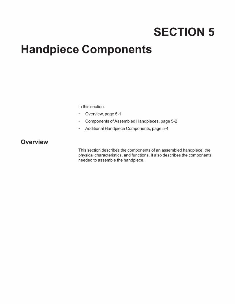
Flue
The single-use flue is a translucent silicone tube tapered at one end that provides a sleeve over the tip. Irrigation fluid flows through an irrigation connection tube at one end of the flue and down the tip to the surgical site.
The single-use flue is sterile in a single use tip pack and nonsterile in an EUT pack.
Each tip size requires a tip-specific flue; therefore, you will find the tip-specific flue packaged with the appropriate tip.
These components are essential in assembling a handpiece.
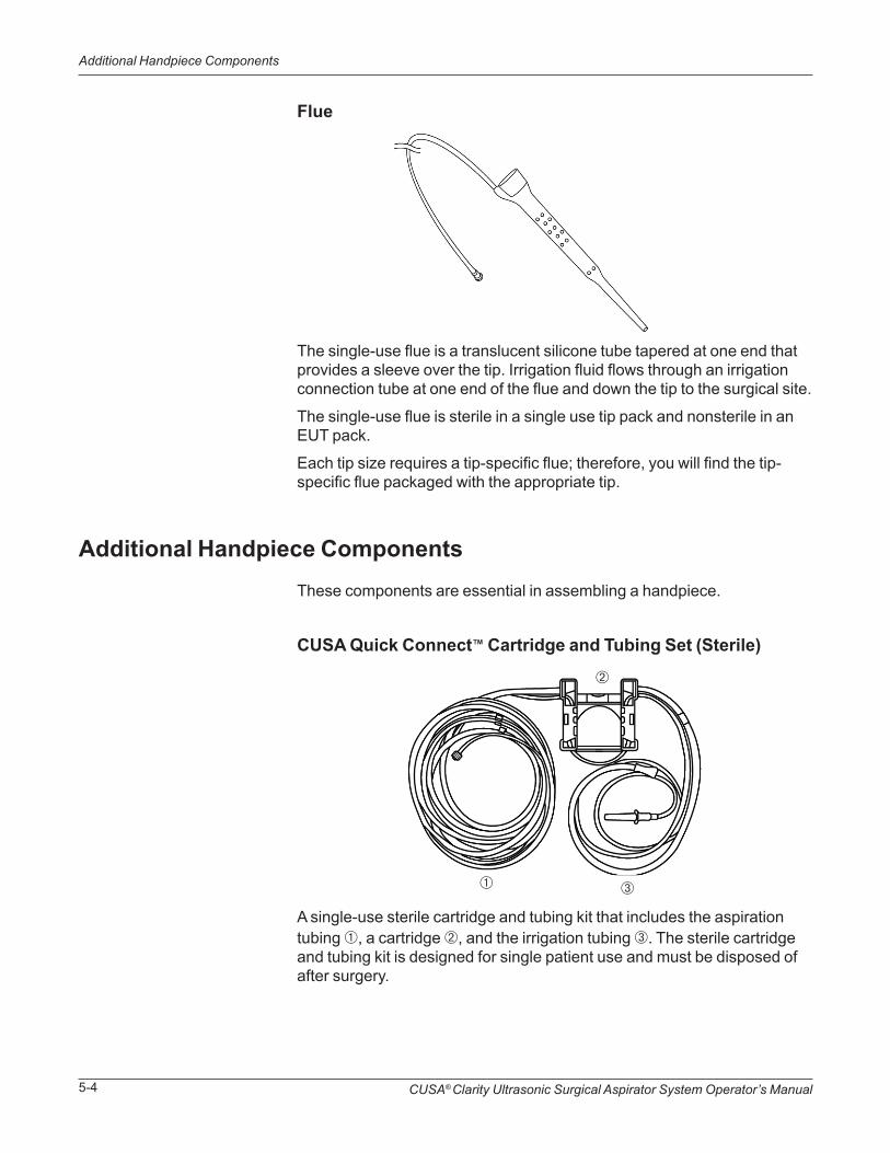
CUSA Quick Connect™ Cartridge and Tubing Set (Sterile)
Additional Handpiece Components
A single-use sterile cartridge and tubing kit that includes the aspiration tubing ➀, a cartridge ➁, and the irrigation tubing ➂. The sterile cartridge and tubing kit is designed for single patient use and must be disposed of after surgery.
➀
➁
➂
CUSA® Clarity Ultrasonic Surgical Aspirator System Operator’s Manual 5-5
Additional Handpiece Components
WARNINGSingle-use devices are for single patient use only. Do not reprocess or re-use.
Aspiration Tubing• Aspirates away used irrigation fluid, fragmented tissue, and other
aspirated materials to the canister
• Connects to the aspiration port at the base of the handpiece, passes through the suction pinch valve, and connects to the aspiration port on the canister
• Contains a small clip to attach to the handpiece cable
Irrigation Tubing• Provides irrigation during the surgical procedure
• Connects to the flue, passes over the peristaltic pump, and connects to a standard IV bag, which can be hung on the console’s IV pole
Cartridge• Connects the aspiration and irrigation tubing to the console
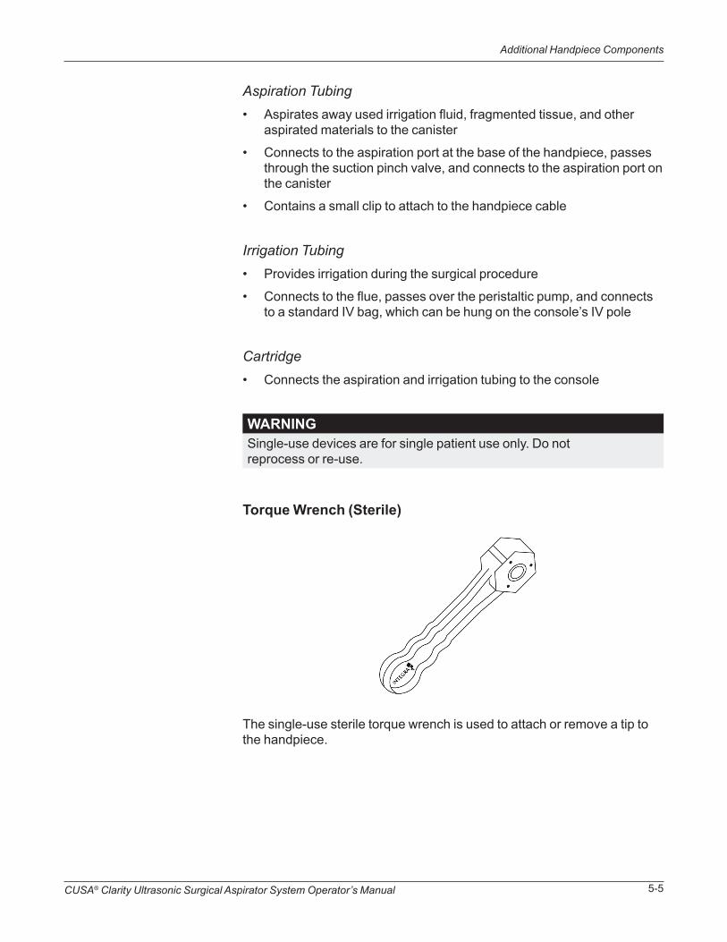
Torque Wrench (Sterile)
The single-use sterile torque wrench is used to attach or remove a tip to the handpiece.
CUSA® Clarity Ultrasonic Surgical Aspirator System Operator’s Manual5-6
Additional Handpiece Components
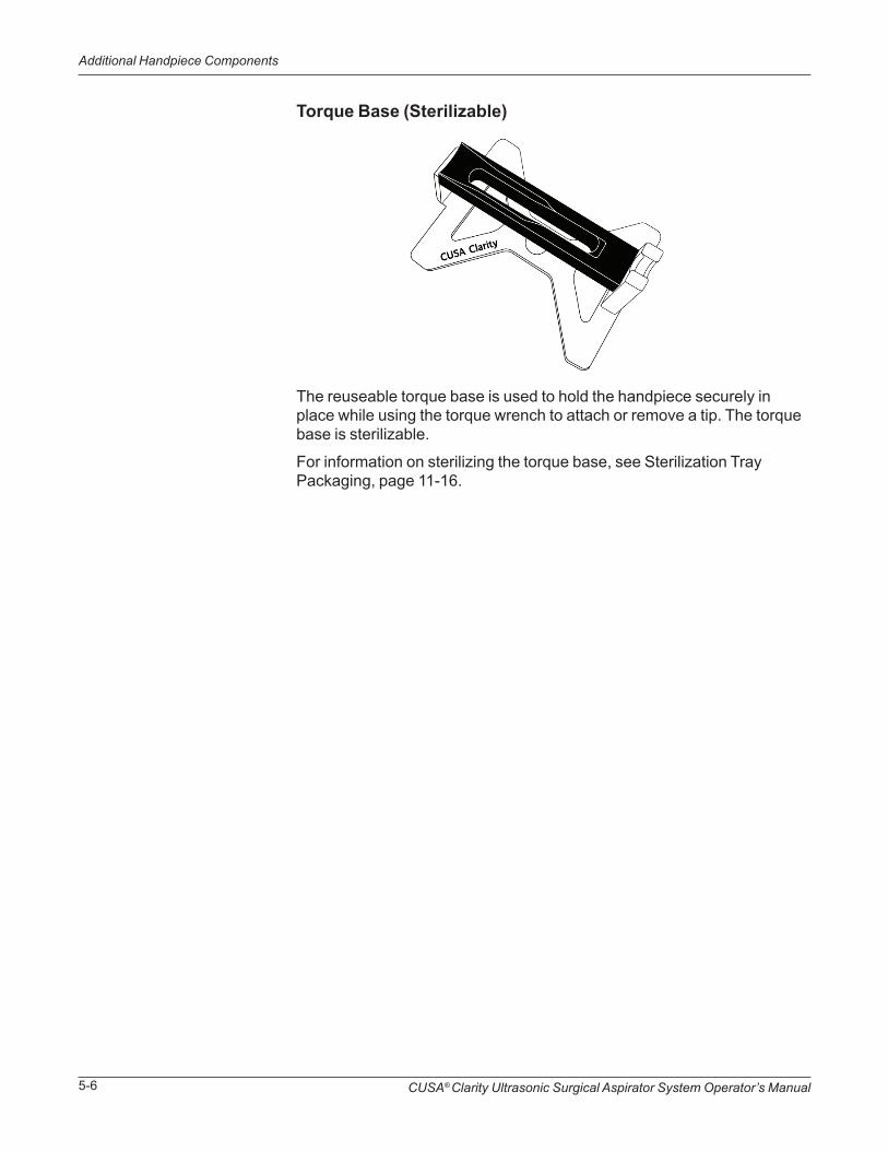
Torque Base (Sterilizable)
The reuseable torque base is used to hold the handpiece securely in place while using the torque wrench to attach or remove a tip. The torque base is sterilizable.
For information on sterilizing the torque base, see Sterilization Tray Packaging, page 11-16.

Assembling the System Prior to UseSECTION 6
Overview
In this section:
• Overview, page 6-1
• Assembling the Console and Cart, page 6-2
• Attaching the Power Cord, page 6-3
This section describes how to assemble the console and cart, and to attach the power cord.
CUSA® Clarity Ultrasonic Surgical Aspirator System Operator’s Manual6-2
Assembling the Console and Cart
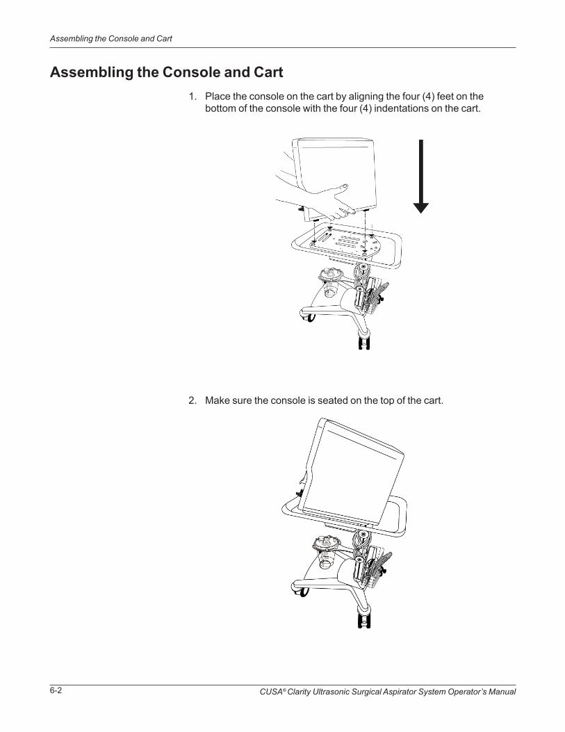
Assembling the Console and Cart1. Place the console on the cart by aligning the four (4) feet on the
bottom of the console with the four (4) indentations on the cart.
2. Make sure the console is seated on the top of the cart.
CUSA® Clarity Ultrasonic Surgical Aspirator System Operator’s Manual 6-3
Assembling the Console and Cart
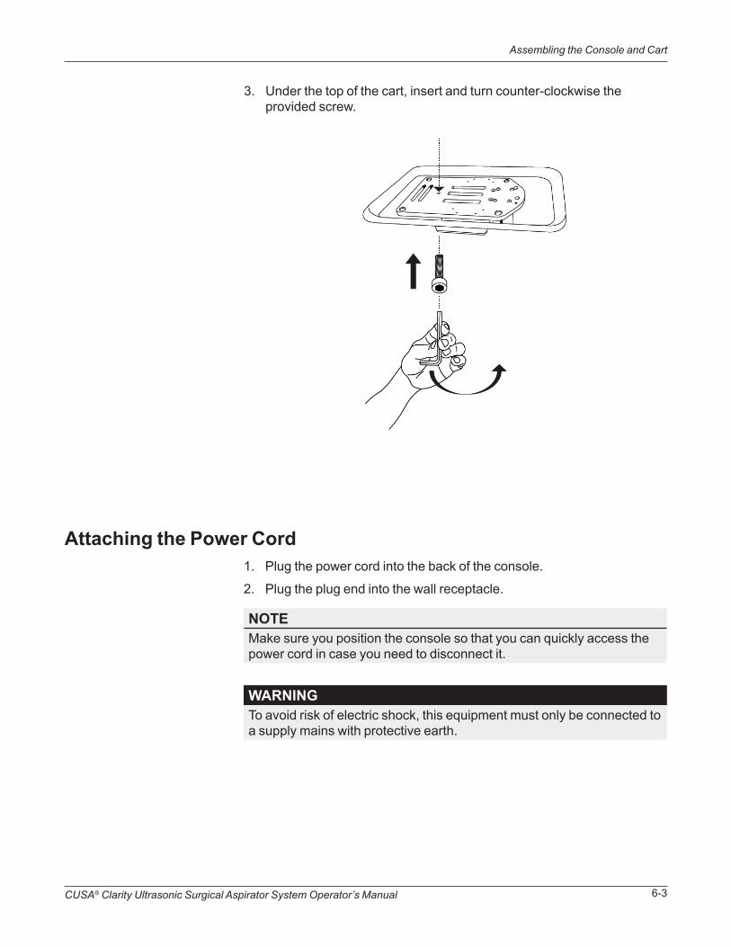
3. Under the top of the cart, insert and turn counter-clockwise the provided screw.
Attaching the Power Cord1. Plug the power cord into the back of the console.
2. Plug the plug end into the wall receptacle.
NOTEMake sure you position the console so that you can quickly access the power cord in case you need to disconnect it.
WARNINGTo avoid risk of electric shock, this equipment must only be connected to a supply mains with protective earth.

CUSA® Clarity Ultrasonic Surgical Aspirator System Operator’s Manual6-4
Assembling the Console and Cart
Intentional Blank

System Setup in the Sterile FieldSECTION 7
In this section:
• Overview on page 7-1
• Quick Reference: Setting Up in the Sterile Field on page 7-2
• Assembling the Handpiece in the Sterile Field on page 7-3
This section describes the steps for setting up the CUSA® Clarity System in the sterile field. It begins with the arrival of the sterilized handpiece and accessories in the operating room. It ends with the handpiece ready to be connected to the console.
Overview
CUSA® Clarity Ultrasonic Surgical Aspirator System Operator’s Manual7-2
Quick Reference: Setting Up in the Sterile Field
WARNINGDo not use a damaged handpiece with the CUSA Clarity system. This may result in injury to the patient or user.
Quick Reference: Setting Up in the Sterile Field1. Attaching a Tip on page 7-3.
2. Attaching the Nosecone and the Flue on page 7-5.
3. Attaching the Tubing on page 7-7.
CUSA® Clarity Ultrasonic Surgical Aspirator System Operator’s Manual 7-3
Assembling the Handpiece in the Sterile Field
WARNINGBefore use, sterilize the torque base in the sterilization tray with the handpiece.
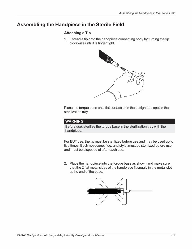
Assembling the Handpiece in the Sterile FieldAttaching a Tip1. Thread a tip onto the handpiece connecting body by turning the tip
clockwise until it is finger tight.
Place the torque base on a flat surface or in the designated spot in the sterilization tray.
2. Place the handpiece into the torque base as shown and make sure that the 2 flat metal sides of the handpiece fit snugly in the metal slot at the end of the base.
For EUT use, the tip must be sterilized before use and may be used up to five times. Each nosecone, flue, and stylet must be sterilized before use and must be disposed of after each use.

CUSA® Clarity Ultrasonic Surgical Aspirator System Operator’s Manual7-4
Assembling the Handpiece in the Sterile Field
3. Hold the handpiece in the base and place the torque wrench (color side towards handpiece) over the tip.
4. Rotate the torque wrench clockwise until it clicks twice.
NOTEKeep the torque wrench and base in the sterile field in case you need to change a tip during the procedure and for disassembly after surgery.
CAUTIONTo avoid product damage, always use the torque base to hold the handpiece while using the torque wrench to tighten or loosen the tip. Avoid over torqueing the tip.

CUSA® Clarity Ultrasonic Surgical Aspirator System Operator’s Manual 7-5
Assembling the Handpiece in the Sterile Field
Attaching the Nosecone and the Flue1. Slide the larger end of the nosecone over the tip and slide it down over
the neck of the handpiece making sure the white dots are aligned.
2. Rotate the nosecone clockwise until it locks into place and the white dot on the nosecone aligns with the while dot on the body of the handpiece.
Make sure the white dots are aligned on the nosecone and handpiece.
3. Slide the flue onto the nosecone base along the tip.
Remove stylet from the flue and put it aside in the sterile field if needed to clear the tip during surgery.

CUSA® Clarity Ultrasonic Surgical Aspirator System Operator’s Manual7-6
Assembling the Handpiece in the Sterile Field
NOTEIf the pre-aspiration holes are completely covered, most of the irrigation fluid may be aspirated back through the handpiece, impairing cavitation, thus reducing tissue ablation efficacy.
4. Make sure that the flue is aligned with the pre-aspiration holes at the distal end of the tip.

CUSA® Clarity Ultrasonic Surgical Aspirator System Operator’s Manual 7-7
Attaching the Tubing
Attaching the Tubing1. Open the CUSA Quick Connect™ Cartridge and Tubing Set using
proper sterile technique.
2. Pick up the larger loop of the irrigation and aspiration tubing set to be brought into the sterile field and assembled to the handpiece.

CUSA® Clarity Ultrasonic Surgical Aspirator System Operator’s Manual7-8
Attaching the Tubing
3. Place the cartridge and smaller loop of the irrigation and aspiration tubing set aside until it is time to connect it to the console.
4. Attach the aspiration tubing to the aspiration port at the base of the handpiece.

CUSA® Clarity Ultrasonic Surgical Aspirator System Operator’s Manual 7-9
Attaching the Tubing
5. Attach the irrigation tubing to the Luer lock fitting on the handpiece flue.

CUSA® Clarity Ultrasonic Surgical Aspirator System Operator’s Manual7-10
Attaching the Tubing
NOTEIf needed, the clip can be rotated to minimize strain on the user’s wrist.
6. Push the irrigation tubing into the clip at the base of the handpiece.
7. Clip the handpiece cable to the aspiration tubing using clips available along the aspiration tubing.
8. Keep sufficient tubing and cable in the sterile field to allow you to reposition the console.
9. Pass off the cartridge and smaller loop of the irrigation and aspiration tubing set and handpiece cable connector outside of the sterile field for attachment to the console.
NOTEHandpiece cable is not intended to be inserted into the clip at the base of the handpiece.

System Setup in the Non-Sterile FieldSECTION 8
Overview
Quick Reference: Setting Up in the Non-Sterile Field
In this section:
• Overview, page 8-1
• Quick Reference: Setting Up in the Non-Sterile Field, page 8-1
• Assembling the Handpiece, page 8-2
• Console Setup (Non-Sterile), page 8-2
This section describes the steps for setting up the CUSA® Clarity System in the non-sterile field.
CAUTIONBefore surgery, apply the brake locks to all wheels on the cart (if using the optional Integra cart) to stop the wheels from rolling.
CAUTIONWhen using the console without a cart, prior to surgery, place the console on a solid surface. The surface must be flat, non-slip, and free from obstruction.
1. Powering Up the System, page 8-2
2. Attaching the Footswitch, page 8-3
3. Attaching the Handpiece, page 8-3
4. Connecting the Tubing Set, page 8-4

CUSA® Clarity Ultrasonic Surgical Aspirator System Operator’s Manual8-2
Console Setup (Non-Sterile)
Assembling the Handpieces
Console Setup (Non-Sterile)
The handpiece must be assembled in a sterile area, see System Setup in the Sterile Field, page 7-1.
Powering Up the SystemPress the System Power On/Off button on the console (Classification and Console Symbols, page 1-9). The console sounds a startup tone.
WARNINGTo ensure sterility, assemble sterile handpiece and tip in the sterile field only.
NOTEThe purpose of the startup tone verifies that the audio alarms are functioning correctly. If this tone does not sound during the startup process, contact Integra for service.

CUSA® Clarity Ultrasonic Surgical Aspirator System Operator’s Manual 8-3
Console Setup (Non-Sterile)
Attaching the HandpieceAfter the handpiece cable connector is passed out from the sterile field, align the red dot on the handpiece cable connector with the red dot on the handpiece port on the front of the console and plug in the handpiece cable.
Attaching the FootswitchAlign the red dot on the footswitch cable connector with the red dot on the footswitch port on the rear of the console and plug in the footswitch cable.

CUSA® Clarity Ultrasonic Surgical Aspirator System Operator’s Manual8-4
Console Setup (Non-Sterile)
WARNINGTo avoid injury to the user, keep fingers away from the peristaltic pump and pinch valve.
Connecting the Tubing Set
1. Place the canister into the canister holder.
2. Open the cartridge door, insert the cartridge, and slide the cartridge down.
NOTEMake sure the handpiece and contamination guard have been properly set up and connected. See the contamination guard instructions for use for information.
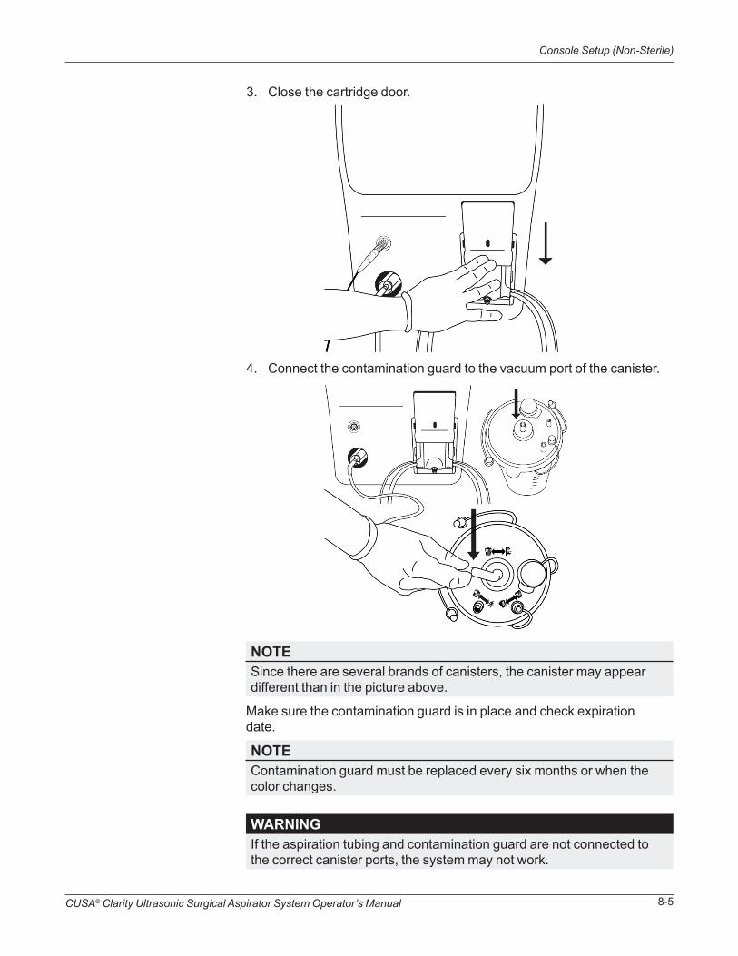
CUSA® Clarity Ultrasonic Surgical Aspirator System Operator’s Manual 8-5
Console Setup (Non-Sterile)
WARNINGIf the aspiration tubing and contamination guard are not connected to the correct canister ports, the system may not work.
3. Close the cartridge door.
4. Connect the contamination guard to the vacuum port of the canister.
Make sure the contamination guard is in place and check expiration date.
NOTEContamination guard must be replaced every six months or when the color changes.
NOTESince there are several brands of canisters, the canister may appear different than in the picture above.

CUSA® Clarity Ultrasonic Surgical Aspirator System Operator’s Manual8-6
Console Setup (Non-Sterile)
5. Connect the aspiration tubing to the patient port of the canister.
6. From the rear of the console, lift the IV pole straight up.
NOTEMake sure the remaining ports on the canister are covered.
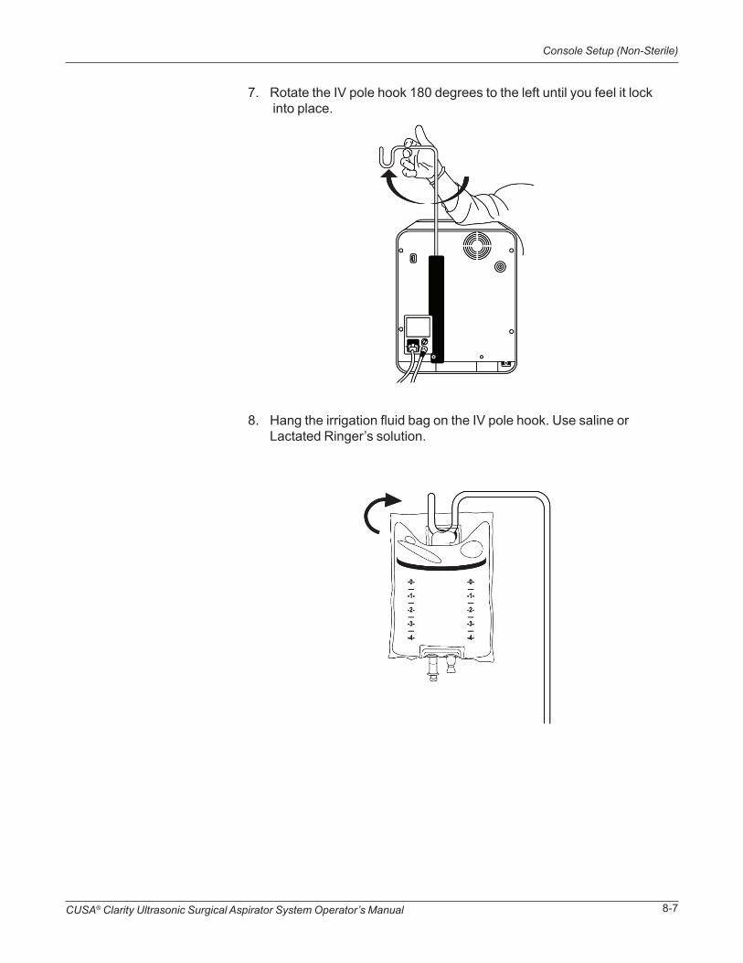
CUSA® Clarity Ultrasonic Surgical Aspirator System Operator’s Manual 8-7
Console Setup (Non-Sterile)
7. Rotate the IV pole hook 180 degrees to the left until you feel it lock into place.
8. Hang the irrigation fluid bag on the IV pole hook. Use saline or Lactated Ringer’s solution.
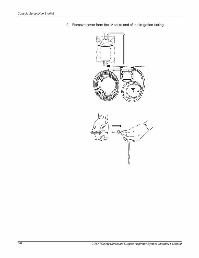
CUSA® Clarity Ultrasonic Surgical Aspirator System Operator’s Manual8-8
Console Setup (Non-Sterile)
9. Remove cover from the IV spike end of the irrigation tubing.
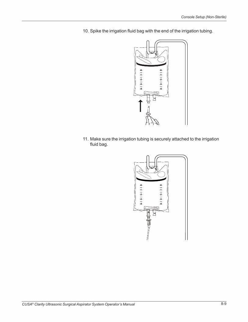
CUSA® Clarity Ultrasonic Surgical Aspirator System Operator’s Manual 8-9
Console Setup (Non-Sterile)
10. Spike the irrigation fluid bag with the end of the irrigation tubing.
11. Make sure the irrigation tubing is securely attached to the irrigation fluid bag.

CUSA® Clarity Ultrasonic Surgical Aspirator System Operator’s Manual8-10
Console Setup (Non-Sterile)
Intentional Blank

WARNINGOperating the CUSA Clarity System outside of the specified environmental conditions may result in injury to the patient and/or user, or equipment damage, which may result in a delay in patient treatment.
Operating the SystemSECTION 9
In this section:
• Overview on page 9-1
• Quick Reference: Operating the System on page 9-2
• Priming the System on page 9-2
• Testing the Handpiece on page 9-4
This section describes the procedures for operating the CUSA® Clarity System for surgery. The system must be properly setup before using it. For specified environmental conditions for operation of the system, see “Environment” on page A-5.
Overview
If the system is not setup, see:
1. “System Setup in the Sterile Field” on page 7-1.
2. “System Setup in the Non-Sterile Field” on page 8-1.
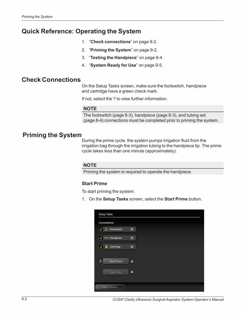
CUSA® Clarity Ultrasonic Surgical Aspirator System Operator’s Manual9-2
Priming the System
Quick Reference: Operating the System
Priming the System
Check Connections
1. “Check connections” on page 9-2.
2. “Priming the System” on page 9-2.
3. “Testing the Handpiece” on page 9-4.
4. “System Ready for Use” on page 9-5.
NOTEThe footswitch (page 8-3), handpiece (page 8-3), and tubing set (page 8-4) connections must be completed prior to priming the system.
NOTEPriming the system is required to operate the handpiece.
During the prime cycle, the system pumps irrigation fluid from the irrigation bag through the irrigation tubing to the handpiece tip. The prime cycle takes less than one minute (approximately).
On the Setup Tasks screen, make sure the footswitch, handpiece and cartridge have a green check mark.
If not, select the ? to view further information.
Start PrimeTo start priming the system:
1. On the Setup Tasks screen, select the Start Prime button.

CUSA® Clarity Ultrasonic Surgical Aspirator System Operator’s Manual 9-3
Priming the System
NOTEThe prime cycle ends automatically; however, if necessary, the cycle may be stopped at any time by selecting the Stop Prime button.
2. Make sure the irrigation tubing is filled with irrigation fluid, and the irrigation fluid flows from the tip.
3. If fluid does not flow from the tip after one prime cycle, select the Start Prime button again.
If irrigation fluid does not flow from the handpiece tip after several prime cycles, see “Irrigation Troubleshooting” on page 13-5.
Stop PrimeTo stop priming the system, during the priming cycle, select the Stop Prime button (the Start Prime button changes to a Stop Prime button during the priming cycle).

CUSA® Clarity Ultrasonic Surgical Aspirator System Operator’s Manual9-4
Testing the Handpiece
NOTEThe footswitch, handpiece, and cartridge connections must be made and a priming cycle completed prior to performing the test.
NOTEThe handpiece must be tested prior to use to ensure proper function.
WARNINGWhen testing the handpiece, do not allow the tip to come in contact with any person or object during tip activation. Contact may result in injury to the patient and/or user, or handpiece tip damage.
Contact with any object or person may cause the test to fail.
Testing the HandpieceDuring the test cycle, the system verifies the handpiece is working properly by automatically increasing tip amplitude to 100% and then decreasing it to 0%. The test cycle takes about 4 seconds (approximately).
After the test cycle completes, the Setup Tasks screen displays either Pass or Fail and a Details button. Select the Details button to display the Detailed Test Results screen with the test results. If the test failed, the Detailed Test Results screen provides the error(s) and solution(s).
For additional troubleshooting information, see “Troubleshooting the System” on page 13-1.
Start TestTo start testing the handpiece:
1. On the Setup Tasks screen, select the Start Test button.
CUSA® Clarity Ultrasonic Surgical Aspirator System Operator’s Manual 9-5
Testing the Handpiece
2. If the test fails:
a. Remove the tip and then re-attach with the torque wrench and base, and re-run the test. If the error continues to persist, attach a new tip with the torque wrench and base, and re-run the test.
b. If the error continues to persist after replacing the tip, replace the entire handpiece.
c. Re-run the test.
3. If the test passes, press the Main Screen button.
After testing the system, a Details button displays. Press this button to view the following detailed test results.
Detailed Test Results• Tip Frequency Optimization - Finds the best frequency for the tip
• Amplitude Test - Measures how close the handpiece is to maximum amplitude and provides a score from 0 to 100%. The score must be greater than or equal to 50% to pass the test
Press the Main Screen button to begin surgical use.
For a description of the settings, see “Section 4 Touchscreen Display and Functions” on page 4-1.
System Ready for Use

CUSA® Clarity Ultrasonic Surgical Aspirator System Operator’s Manual9-6
Testing the Handpiece
Intentional Blank

Changing Tips in the Sterile Field During a Surgical Procedure
SECTION 10
In this section:
• Overview on page 10-1
• Quick Reference: Changing Tips on page 10-1
• Changing a Tip on page 10-2
This section describes the procedures for changing tips during surgery while in the sterile field.
Overview
Quick Reference: Changing Tips
1. Put the system in standby.
2. “Removing the Used Tip” on page 10-2.
3. “Assembling the New Tip on the Handpiece” on page 10-6.
4. Test and prime the handpiece again.
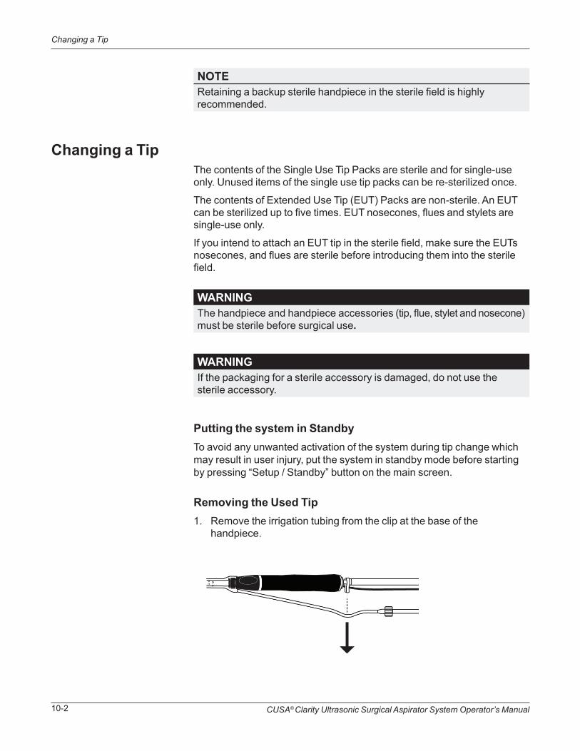
CUSA® Clarity Ultrasonic Surgical Aspirator System Operator’s Manual10-2
Changing a Tip
NOTERetaining a backup sterile handpiece in the sterile field is highly recommended.
WARNINGThe handpiece and handpiece accessories (tip, flue, stylet and nosecone) must be sterile before surgical use.
WARNINGIf the packaging for a sterile accessory is damaged, do not use the sterile accessory.
Changing a TipThe contents of the Single Use Tip Packs are sterile and for single-use only. Unused items of the single use tip packs can be re-sterilized once.
The contents of Extended Use Tip (EUT) Packs are non-sterile. An EUT can be sterilized up to five times. EUT nosecones, flues and stylets are single-use only.
If you intend to attach an EUT tip in the sterile field, make sure the EUTs nosecones, and flues are sterile before introducing them into the sterile field.
Putting the system in StandbyTo avoid any unwanted activation of the system during tip change which may result in user injury, put the system in standby mode before starting by pressing “Setup / Standby” button on the main screen.
Removing the Used Tip1. Remove the irrigation tubing from the clip at the base of the
handpiece.

CUSA® Clarity Ultrasonic Surgical Aspirator System Operator’s Manual 10-3
Changing a Tip
2. Remove the irrigation tubing from the Luer fitting on the handpiece flue.
3. Slide the flue off of the nosecone base.
4. Twist off the nosecone counter-clockwise until it unlocks.

CUSA® Clarity Ultrasonic Surgical Aspirator System Operator’s Manual10-4
Changing a Tip
5. Slide the nosecone off the tip.
6. Place the handpiece on the torque base as shown and make sure that the 2 flat metal sides fit snugly in the metal slot at the end of the base.
7. Hold the handpiece in the base and place the torque wrench (color side towards handpiece) over the tip.
CAUTIONTo avoid product damage, always use the torque base to hold the handpiece while using the torque wrench to tighten or loosen the tip. Avoid over torqueing the tip.
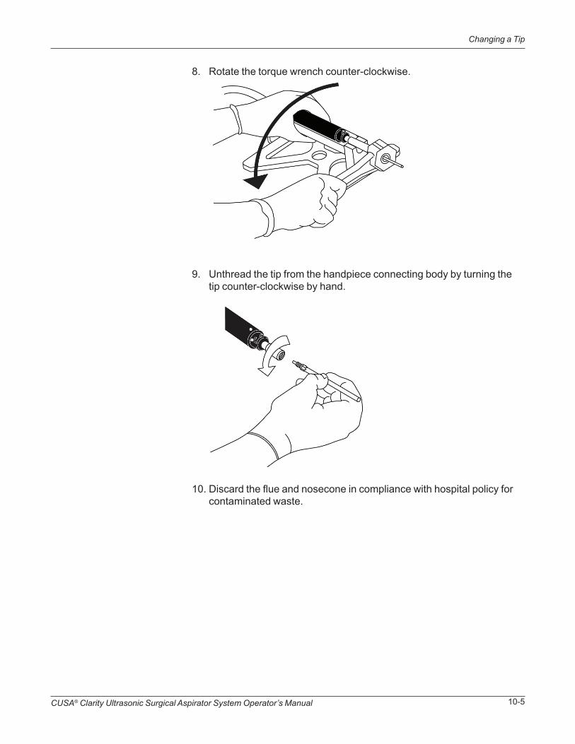
CUSA® Clarity Ultrasonic Surgical Aspirator System Operator’s Manual 10-5
Changing a Tip
8. Rotate the torque wrench counter-clockwise.
9. Unthread the tip from the handpiece connecting body by turning the tip counter-clockwise by hand.
10. Discard the flue and nosecone in compliance with hospital policy for contaminated waste.
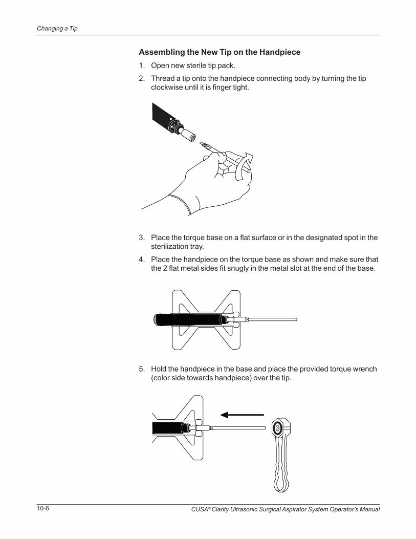
CUSA® Clarity Ultrasonic Surgical Aspirator System Operator’s Manual10-6
Changing a Tip
Assembling the New Tip on the Handpiece1. Open new sterile tip pack.
2. Thread a tip onto the handpiece connecting body by turning the tip clockwise until it is finger tight.
3. Place the torque base on a flat surface or in the designated spot in the sterilization tray.
4. Place the handpiece on the torque base as shown and make sure that the 2 flat metal sides fit snugly in the metal slot at the end of the base.
5. Hold the handpiece in the base and place the provided torque wrench (color side towards handpiece) over the tip.
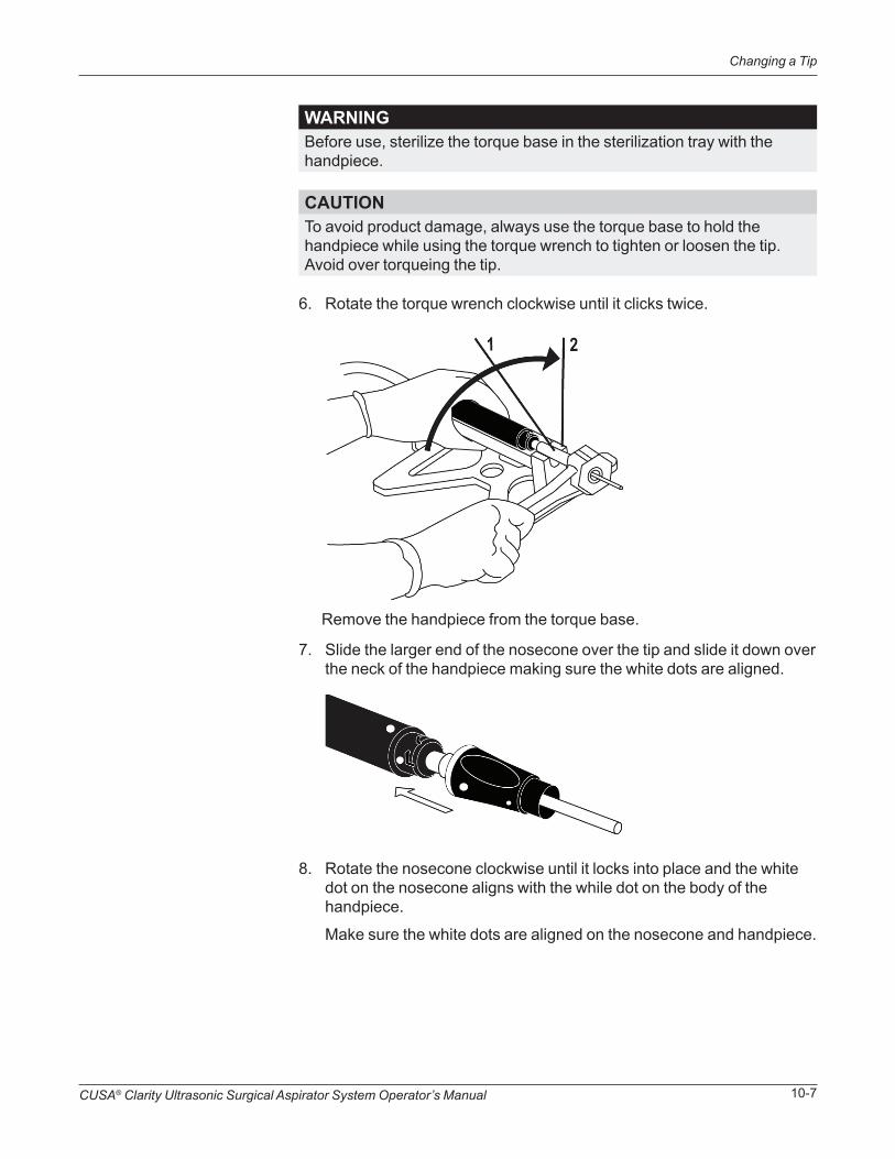
CUSA® Clarity Ultrasonic Surgical Aspirator System Operator’s Manual 10-7
Changing a Tip
CAUTIONTo avoid product damage, always use the torque base to hold the handpiece while using the torque wrench to tighten or loosen the tip. Avoid over torqueing the tip.
WARNINGBefore use, sterilize the torque base in the sterilization tray with the handpiece.
6. Rotate the torque wrench clockwise until it clicks twice.
7. Slide the larger end of the nosecone over the tip and slide it down over the neck of the handpiece making sure the white dots are aligned.
8. Rotate the nosecone clockwise until it locks into place and the white dot on the nosecone aligns with the while dot on the body of the handpiece.
Make sure the white dots are aligned on the nosecone and handpiece.
Remove the handpiece from the torque base.

CUSA® Clarity Ultrasonic Surgical Aspirator System Operator’s Manual10-8
Changing a Tip
9. Slide the flue onto the nosecone base along the tip.
10. Make sure that the flue is aligned with the pre-aspiration holes at the distal end of the tip.
NOTEIf the pre-aspiration holes are completely covered, most of the irrigation fluid may be aspirated back through the handpiece, impairing cavitation, thus reducing tissue ablation efficacy.
Remove stylet from the flue and put it aside in the sterile field if needed to clear the tip during surgery.

CUSA® Clarity Ultrasonic Surgical Aspirator System Operator’s Manual 10-9
Changing a Tip
11. Attach the irrigation tubing to the Luer lock fitting on the handpiece flue.

CUSA® Clarity Ultrasonic Surgical Aspirator System Operator’s Manual10-10
Changing a Tip
12. Push the irrigation tubing into the clip at the base of the handpiece.
NOTEIf needed, the clip can be rotated to minimize strain on the user’s wrist.
NOTEHandpiece cable is not intended to be inserted into the clip at the base of the handpiece.
13. Prime the irrigation and test the handpiece before starting to use the handpiece again by pressing “start prime” and “start test”.

Disassembling, Cleaning, and Sterilizing the System
SECTION 11
In this section:
• Overview on page 11-1
• Quick Reference: Disassembling the System on page 11-1
• Quick Reference: Cleaning the System on page 11-2
• Disassembling the System on page 11-2
• Cleaning the System on page 11-11
• Sterilizing the System on page 11-14
• Sterilization Parameters on page 11-16
This section describes how to disassemble the system and clean the console, handpiece, and components.
Overview
Quick Reference: Disassembling the System
1. “Disassembling the Handpiece” on page 11-2.
2. “Disassembling the Console” on page 11-7.
3. “Powering Down the System” on page 11-10.
4. “Detaching the Contamination Guard” on page 11-10
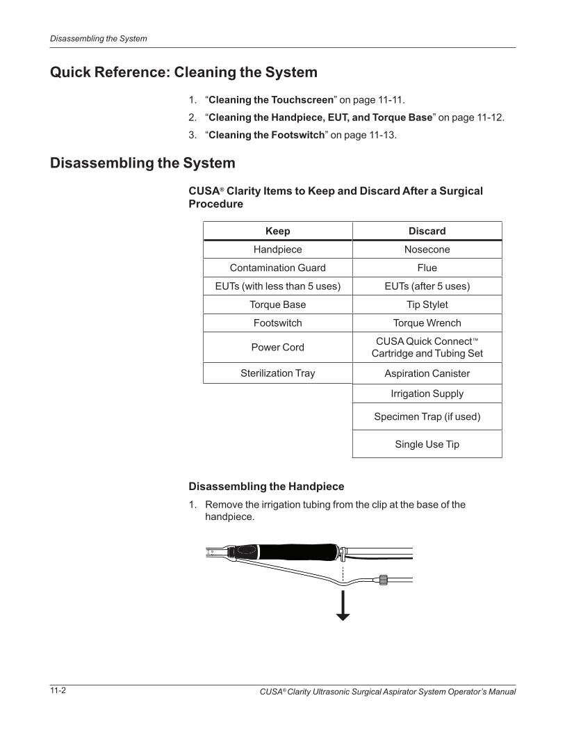
CUSA® Clarity Ultrasonic Surgical Aspirator System Operator’s Manual11-2
Disassembling the System
Quick Reference: Cleaning the System
Disassembling the System
1. “Cleaning the Touchscreen” on page 11-11.
2. “Cleaning the Handpiece, EUT, and Torque Base” on page 11-12.
3. “Cleaning the Footswitch” on page 11-13.
CUSA® Clarity Items to Keep and Discard After a Surgical Procedure
Disassembling the Handpiece1. Remove the irrigation tubing from the clip at the base of the
handpiece.
Discard
Nosecone
Flue
EUTs (after 5 uses)
Tip Stylet
Torque Wrench
CUSA Quick Connect™ Cartridge and Tubing Set
Aspiration Canister
Irrigation Supply
Specimen Trap (if used)
Single Use Tip
Keep
Handpiece
Contamination Guard
EUTs (with less than 5 uses)
Torque Base
Footswitch
Power Cord
Sterilization Tray

CUSA® Clarity Ultrasonic Surgical Aspirator System Operator’s Manual 11-3
Disassembling the System
2. Remove the handpiece cable from the aspiration tubing clips.
3. Remove the aspiration tubing from the aspiration port at the base of the handpiece.

CUSA® Clarity Ultrasonic Surgical Aspirator System Operator’s Manual11-4
Disassembling the System
4. Remove the irrigation tubing from the Luer fitting on the handpiece flue.
5. Slide the flue off of the nosecone base along the tip.
6. Twist off the nosecone counter-clockwise until it unlocks.

CUSA® Clarity Ultrasonic Surgical Aspirator System Operator’s Manual 11-5
Disassembling the System
7. Slide the nosecone off the tip.
8. Place the handpiece on the torque base as shown and make sure that the 2 flat metal sides fit snugly in the metal slot at the end of the base.
9. Hold the handpiece in the base and place the torque wrench (color side towards handpiece) over the tip.
CAUTIONTo avoid product damage, always use the torque base to hold the handpiece while using the torque wrench to tighten or loosen the tip. Avoid over torqueing the tip.
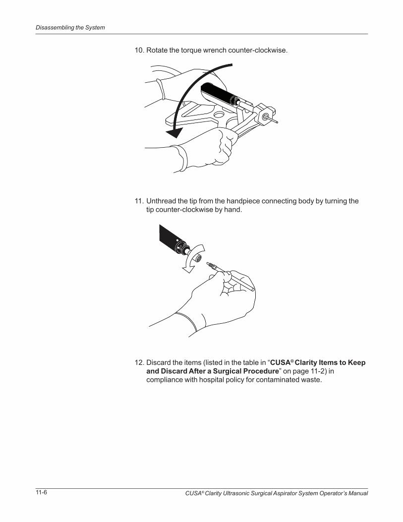
CUSA® Clarity Ultrasonic Surgical Aspirator System Operator’s Manual11-6
Disassembling the System
10. Rotate the torque wrench counter-clockwise.
11. Unthread the tip from the handpiece connecting body by turning the tip counter-clockwise by hand.
12. Discard the items (listed in the table in “CUSA® Clarity Items to Keep and Discard After a Surgical Procedure” on page 11-2) in compliance with hospital policy for contaminated waste.

CUSA® Clarity Ultrasonic Surgical Aspirator System Operator’s Manual 11-7
Disassembling the System
NOTEThe contamination guard should not be removed from the console unless it is time to replace it (every six months or when the color changes).
Disassembling the Console1. Detach the aspiration tubing from the patient port on the canister.
2. Disconnect the contamination guard tubing from the vacuum port of the canister.

CUSA® Clarity Ultrasonic Surgical Aspirator System Operator’s Manual11-8
Disassembling the System
3. Open cartridge door, if necessary press the pinch valve button, and remove the cartridge from the console by sliding it up.
4. Detach the handpiece cable from the console by gently pulling on the handpiece cable connector in the handpiece port on the front of the console.

CUSA® Clarity Ultrasonic Surgical Aspirator System Operator’s Manual 11-9
Disassembling the System
5. Unplug the power cord from the wall receptacle and the console.
6. Disconnect the footswitch cable connector from the back of the console.
7. Discard the used/contaminated items in compliance with hospital policy for contaminated waste.
Please reference the table “CUSA® Clarity Items to Keep and Discard After a Surgical Procedure” on page 11-2.
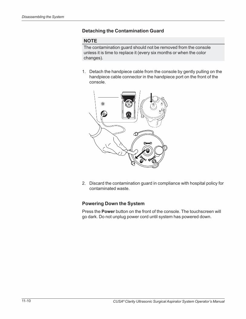
CUSA® Clarity Ultrasonic Surgical Aspirator System Operator’s Manual11-10
Disassembling the System
Detaching the Contamination Guard
NOTEThe contamination guard should not be removed from the console unless it is time to replace it (every six months or when the color changes).
1. Detach the handpiece cable from the console by gently pulling on the handpiece cable connector in the handpiece port on the front of the console.
2. Discard the contamination guard in compliance with hospital policy for contaminated waste.
Powering Down the SystemPress the Power button on the front of the console. The touchscreen will go dark. Do not unplug power cord until system has powered down.

CUSA® Clarity Ultrasonic Surgical Aspirator System Operator’s Manual 11-11
Cleaning the System
NOTEDo not wipe the touch screen with a sponge because it may scratch the surface.
NOTENever apply cleaner directly to the touch screen.
WARNINGDo not allow fluids to enter the console.
WARNINGElectric Shock Hazard - Always unplug the CUSA Clarity System before cleaning it.
CAUTIONProduct damage may result if you do not follow the instructions described in the cleaning section.
Cleaning the System
Cleaning the TouchscreenMake sure to the console is unplugged before cleaning it. Clean the touch screen with a lint-free wipe and a cleaner, such as window/glass cleaner, eyeglass cleaner, or a quaternary ammonia disinfectant.
Cleaning the Console and Cart
1. Unplug the power cord from the wall receptacle and the console.
2. Clean the surface with a lint-free wipe soaked with one of the following:
• 70% IPA
• Super Sani-Cloth®
• Sani-Cloth® Bleach
3. Make sure the surfaces remain visibly wet for a minimum of two (2) minutes, then air dry.
CUSA® Clarity Ultrasonic Surgical Aspirator System Operator’s Manual11-12
Cleaning the System
4. Clean the wheels at the base of the system cart to ensure that the four anti-static wheels function correctly.
NOTEMake sure that the surface of the wheels is free from dirt and dust. Make sure that the surface is completely dry before using the system again.
NOTEMake sure to keep the handpiece cable connector dry.
Cleaning the Handpiece, EUT, and Torque BaseThe handpiece, extended use tips, and torque base may be cleaned by either the manual cleaning or autowash cycle process prior to sterilization. For Sterlization Parameter, see “Sterilizing the System” on page 11-14.
Manual Cleaning
1. Use the provided cleaning brush to clean out the internal channels of both the handpiece and tip. Continue to pass the brush through the tip and handpiece until it comes out clean.
2. Clean the exterior of the handpiece and tip with a lint free cloth soaked with warm water and a non-alkaline detergent.
3. Use the cloth to manually clean the junction where the tip attaches.
4. Rinse the entire handpiece and tip thoroughly with water and dry with a soft cloth.
Autowash Cycle:
Before auto washing, use the provided cleaning brush to thoroughly clean the internal channels of the handpiece and tip. Continue to pass the brush through the tip and handpiece until it comes out clean.
In a Steelco DS50 DRS or equivalent washer/disinfector, perform a prewash cycle of 5 minutes, then clean using a 1% solution of alkaline detergent (neodisher® MediClean forte or equivalent, final pH between 10.0-11.5) for 10 minutes at 60°C (140°F), disinfect for 10 minutes at 93°C (199.4°F), and dry for 20 minutes.

CUSA® Clarity Ultrasonic Surgical Aspirator System Operator’s Manual 11-13
Cleaning the System
NOTEMake sure to keep the connector dry.
NOTEDo not clean the sterilizer tray with abrasives. Product damage will result.
Cleaning the Footswitch1. Disconnect the footswitch from the console.
2. Wipe it clean.
3. If the footswitch is contaminated with blood or fluid:
a. Immerse the footswitch in warm water containing detergent or disinfectant.
b. Rinse the footswitch with clean water.
4. Allow the footswitch to drain after rinsing.
Sterilization Tray CleaningUse a neutral detergent to clean the tray.

CUSA® Clarity Ultrasonic Surgical Aspirator System Operator’s Manual11-14
Sterilizing the System
Sterilizing the SystemPackaging the Handpiece and Components for SterilizationThe handpiece and components need to be packaged for sterilization.
Integra provides a sterilization tray for steam sterilization of the CUSA Clarity handpiece. This tray protects the handpiece during sterilization and during transfer to the sterile field. The handpiece and components must be cleaned prior to sterilization, see “Cleaning the Handpiece, EUT, and Torque Base” on page 11-12.
Sterilization Tray Layout
➀➁
➂ ➃
➄➅
➆
➀ Handpiece ➄ Flue and Stylet
➁ Handpiece Cable Posts ➅ Torque Base
➂ Handpiece Connector ➆ EUT Slots (3)
➃ Nosecone ➇ Lid (Not shown)
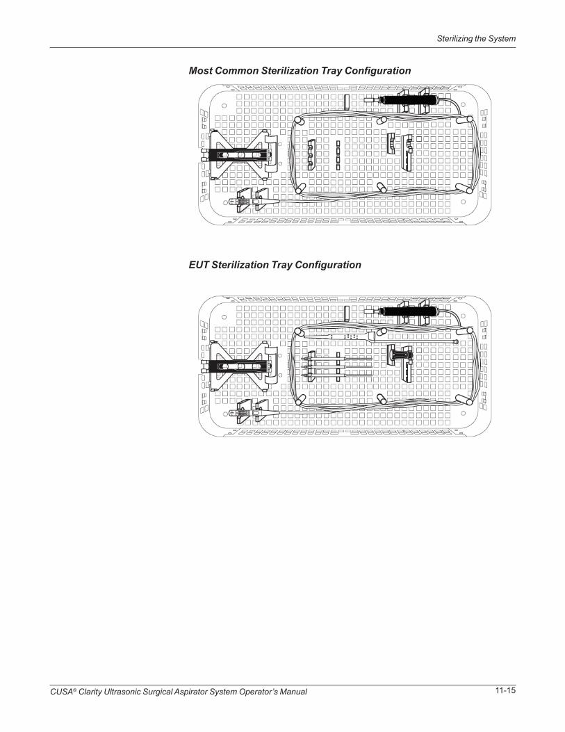
CUSA® Clarity Ultrasonic Surgical Aspirator System Operator’s Manual 11-15
Sterilizing the System
Most Common Sterilization Tray Configuration
EUT Sterilization Tray Configuration
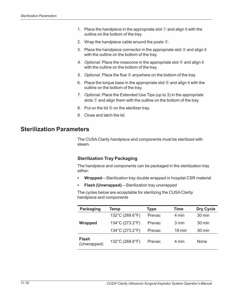
CUSA® Clarity Ultrasonic Surgical Aspirator System Operator’s Manual11-16
Sterilization Parameters
1. Place the handpiece in the appropriate slot ➀ and align it with the outline on the bottom of the tray.
2. Wrap the handpiece cable around the posts ➁.
3. Place the handpiece connector in the appropriate slot ➂ and align it with the outline on the bottom of the tray.
4. Optional. Place the nosecone in the appropriate slot ➃ and align it with the outline on the bottom of the tray.
5. Optional. Place the flue ➄ anywhere on the bottom of the tray.
6. Place the torque base in the appropriate slot ➅ and align it with the outline on the bottom of the tray.
7. Optional. Place the Extended Use Tips (up to 3) in the appropriate slots ➆ and align them with the outline on the bottom of the tray.
8. Put on the lid ➇ on the sterilizer tray.
9. Close and latch the lid.
Sterilization ParametersThe CUSA Clarity handpiece and components must be sterilized with steam.
Sterilization Tray PackagingThe handpiece and components can be packaged in the sterilization tray either:
• Wrapped—Sterilization tray double wrapped in hospital CSR material
• Flash (Unwrapped)—Sterilization tray unwrapped
The cycles below are acceptable for sterilizing the CUSA Clarity handpiece and components
Packaging Temp Type Time Dry Cycle
Wrapped
132°C (269.6°F)
134°C (273.2°F)
134°C (273.2°F)
Prevac
Prevac
Prevac
4 min
3 min
18 min
30 min
30 min
30 min
Flash (Unwrapped) 132°C (269.6°F) Prevac 4 min None
CUSA® Clarity Ultrasonic Surgical Aspirator System Operator’s Manual 11-17
Sterilization Parameters
Sterilizing the Handpiece and Components with SteamSterilizing the handpiece with steam depends on the following factors:
• Temperature
• Exposure time
• Population and resistance of resident bioburden
• Method of air removal from the autoclave
Use the validated steam sterilization cycle parameters in these instructions. If you deviate from this recommended method of sterilizing, it is your Health Care Facility’s responsibility to validate the deviation. For sterilizing the handpiece with steam, do not exceed 134°C (273.2°F).
CAUTIONDo not use sterilization methods involving temperatures in excess of 134ºC (273.2°F) as this may damage the handpiece.

CUSA® Clarity Ultrasonic Surgical Aspirator System Operator’s Manual11-18
Sterilization Parameters
Intentional Blank
Maintaining the SystemSECTION 12
In this section:
• Overview on page 12-1
• Quick Reference on page 12-2
• Handpiece Maintenance on page 12-2
• Handling and Transporting of the System on page 12-3
• Storage of the System and Accessories on page 12-3
• Disposal of the Equipment on page 12-4
• Return Equipment for Service on page 12-4
• Integra Service Centers on page 12-6
This section describes routine maintenance tasks for the system. Biomedical Engineering at the facility should perform these tasks.It also describes handling and storage information for the system, and information on returning equipment to Integra for service.
Annual preventive maintenance and testing is required to inspect for any possible wear that will degrade your CUSA® Clarity System’s essential performance or operation. Being proactive in your CUSA Clarity preventive maintenance program ensures your equipment will run at optimal capability for longer, allowing you to get the most from your tissue ablation device, protecting your patients, users, and your financial investment.
Overview
WARNINGNo modification of this equipment is allowed.

CUSA® Clarity Ultrasonic Surgical Aspirator System Operator’s Manual12-2
Handpiece Maintenance
WARNINGElectrical Shock Hazard - Do not remove cover. Refer servicing to authorized service personnel.
Quick Reference
Handpiece Maintenance
The following chart lists routine maintenance tasks, when you perform each task, and the equipment on which you perform them.
Return and Replace the HandpieceThe handpiece has been validated to 50 hours of ultrasonic usage (i.e. with foot pedal depressed) and 200 procedures. To ensure optimal performance, it is recommended that you replace the handpiece once it reaches 50 hours or 200 procedures, whichever comes first. The tracking of ultrasonic usage hours and the recommendation to replace the handpiece are to support patients and users by following the recommendations outlined in the FDA Guidance Document issued March 17, 2015, “Reprocessing Medical Devices in Health Care Settings: Validation Methods and Labeling” and by complying with applicable international standards.
To view the hours of use, with the handpiece connected, go to the Settings screen (see “Settings Screen” on page 4-3).
Integra recommends that you retain a spare, sterile handpiece for every surgical procedure.
When Equipment Task
Daily or when used Console Clean and wipe dry.
Daily or when used Footswitch Clean the footswitch.
Every 6 months, or when filter changes color
Contamination Guard Replace the contamination guard. Write either the installation date or the expiration date on the guard.
After 50 hours of use, or 200 surgical procedures, whichever comes first
HandpieceReturn handpiece to Integra and replace with a new handpiece.
CUSA® Clarity Ultrasonic Surgical Aspirator System Operator’s Manual 12-3
CAUTIONTo move the console up or down a ramp, use two or more people.
Handpiece Maintenance
Handling and Transportation of the System
Storage of the System and Accessories
If you need to move/relocate the CUSA Clarity Ultrasonic Surgical Aspirator System within the environment of the Healthcare Facility, note the guidelines below:
Before moving the console:
• Power off the system.
• Unplug the power cord from the wall receptacle and secure it.
• Disconnect the handpiece.
• Disconnect and remove the irrigation fluid bag.
• Lower the IV pole.
• Secure any loose objects. Make sure there are no loose objects placed on the top of the console.
• Secure the footswitch and cord.
When moving the console (if attached to a cart):
• Push the cart using the handle.
• Do not run while pushing the console and cart.
• Use an elevator to move the console between floors of a building. Never use a stairwell.
• Do not attempt to lift the console while attached to the cart.
Console• Make sure the system is clean. Store the system in a low traffic area
that is free of dirt, blood, water, and other contaminants.
• Contamination guard may be stored with console if it is not expired.
• Store the system at an ambient temperature between -20°C (-4°F) and 60°C (154°F).
Console with Cart• Wrap footswitch cord around cart and store footswitch in cart basket.
• Wrap power cord around cart.

CUSA® Clarity Ultrasonic Surgical Aspirator System Operator’s Manual12-4
Return Equipment for Service
• Make sure the system is clean. Store the system in a low traffic area that is free of dirt, blood, water, and other contaminants.
• Contamination guard may be stored with console if it is not expired.
• Store the system at an ambient temperature between -20°C (-4°F) and 60°C (154°F).
Handpiece• Store the handpiece and torque base in the sterilizer case according
to your facility’s policy.
• Store the system at an ambient temperature between -20°C (-4°F) and 60°C (154°F).
FootswitchYou do not need to disconnect the footswitch from the console except for maintenance or service. When you are not using CUSA Clarity System, secure the footswitch cord.
The CUSA Clarity Ultrasonic Surgical Aspirator System console, handpiece, and footswitch are considered electrical equipment and must be disposed of in accordance with regional regulation hospital protocols.
Before you return CUSA Clarity equipment, call your Integra representative for help. If the representative tells you to send the equipment to Integra, first obtain a Return Authorization Number, then clean the equipment, and ship it to Integra for service.
Obtaining a Return Authorization NumberCall the Integra Service Center for your area (refer to Integra Service Centers in this section) to obtain a Return Authorization Number. Have the following information ready when you call:
• Hospital/clinic name/customer number
• Telephone number
• Department/address, city, state, and zip or postal code
Disposal of the Equipment
Return Equipment for Service

CUSA® Clarity Ultrasonic Surgical Aspirator System Operator’s Manual 12-5
Return Equipment for Service
• Model number
• Serial number
• Description of the problem
• Type of repair to be done
Attach a tag with this same information to the equipment when you ship it for service.
Returning the ConsoleClean the console and touchscreen before you package it for shipping.
For instructions on packing the console properly, contact your Integra representative.
Returning the HandpieceClean and sterilize the handpiece before you package it for shipping.
Package the handpiece to protect the handpiece and handpiece cable connector from damage.
Package each handpiece in a separate packaging container.
Ordering Replacement PartsThe following replacement parts may be ordered from Integra:
When ordering replacement parts for equipment, include the following information:
• Model number (located on the CUSA Clarity console rear panel)
• Serial number (located on the CUSA Clarity console rear panel)
NOTETo avoid product damage, use proper packaging materials and packing procedures when preparing the console for shipment. Failure to return product in this manner may void your warranty.
• I.V. Pole
• Power Cord
• Footswitch
• Contamination Guard

CUSA® Clarity Ultrasonic Surgical Aspirator System Operator’s Manual12-6
Integra Service Centers
Integra Service Centers
US Service CenterIntegra Neurosciences 5965 Pacific Center Blvd Suite 705 San Diego, CA 92121
Tel: 800-815-1115 Option 5 Fax: 858-455-5874
E-mail: [email protected]
Europe, Middle East and Africa Service CenterIntegra Neurosciences GmbH Halskestrasse 9 Ratingen 40880 Germany
Tel: +49 2102 5535 6150 Fax: +49 2102 942 4872
E-mail: [email protected]
Asia Pacific Service CenterIntegra NeuroSciences Pty. Ltd. Unit 3, 24-30 Winterton Road CLAYTON, VIC. 3168, Australia
Tel: +613 85400400 Fax: +613 95400004
E-mail: [email protected]

Troubleshooting the SystemSECTION 13
In this section:• Overview on page 13-1
• Extracting Log Files on page 13-2
• Technical Messages on page 13-3
• Aspiration Troubleshooting on page 13-5
• Irrigation Troubleshooting on page 13-5
This section describes troubleshooting procedures for the CUSA® Clarity system. It describes how to extract log files and resolve an alarm message on the system.
Overview

CUSA® Clarity Ultrasonic Surgical Aspirator System Operator’s Manual13-2
Alarm Descriptions
NOTEThe external USB drive should be a FAT, FAT32, exFAT or NTFS formatted drive. Other file formats are not supported.
NOTEWhen the extraction is complete, a message to remove the USB drive displays.
Extracting Log Files
Alarm Descriptions
1. From the Main Screen, press the Settings button .
2. Press System Information.
3. Attach a USB drive to the USB connector on the rear of the console.
4. Press the Extract Log button.
5. Remove the USB drive.
Condition Cause Recommendation
Low Aspiration
The console has measured the aspiration level to be too low to be functioning properly.
• Check tubing connections and routing
• Replace tubing set if problem persists
Handpiece Failure
A fault has occurred reading or writing to the handpiece memory chip.
• Disconnect and reconnect handpiece
• Replace handpiece if problem persists
Footswitch FailureA footswitch wiring or connection fault has been detected.
• Disconnect and reconnect footswitch
• Replace footswitch if problem persists
Console Overheating
A high temperature has been measured within the console. The console will automatically shut off.
Contact Integra Service

CUSA® Clarity Ultrasonic Surgical Aspirator System Operator’s Manual 13-3
Amplitude Troubleshooting
Technical Messages
Amplitude Troubleshooting
Condition Cause Recommendation
Console Failure (Recoverable)
A fault has occurred when restoring the previously used settings or service information; default values may be used.
System is usable, but notify Integra Service
Console FailureA fault condition has been detected within the console.
Restart console, contact Integra Service if problem persists
Condition RecommendationFan Failure Contact Integra Service
Low Battery System is usable, but notify service
Condition Recommendation
Amplitude Indicator bar not equal to selected amplitude, or pulsing erratically
• On Tissue Select® 3-High, or 4-Maximum, Amplitude Indicator is always lower than selected amplitude.
• During aggressive tissue fragmentation, small amplitude drops may briefly occur.
• If Amplitude Indicator is persistently low or erratic:
• Stop vibration; allow handpiece to cool.
• Return to Setup screen and repeat handpiece test.

CUSA® Clarity Ultrasonic Surgical Aspirator System Operator’s Manual13-4
Amplitude Troubleshooting
Condition Recommendation
Ineffective fragmentation (due to frequency drift - temperature dependence)
1. Go into standby.
2. Run handpiece test to update the frequency optimization.
No fragmentation while using CUSA Clarity in conjunction with a monopolar electrosurgery system
1. Go into standby.
2. Press Start Prime.
3. Press Stop Prime.
4. Press Start Test.
5. Press Main Screen.
Low or no aspiration
1. Check aspiration at the end of the tip to make sure the aspiration is being delivered to the distal end of the tip.
2. Check tubing and connections for leaks.
3. Verify connections to canister.
4. Utilize the stylet to clear the clog.
WARNINGTo avoid injury or damage to equipment, place system in standby prior to changing tip or clearing a clog.
NOTETo avoid tip blockage during surgery flush with saline solution in between uses. This removes debris before it can dry and block the tip while it is not in use.

CUSA® Clarity Ultrasonic Surgical Aspirator System Operator’s Manual 13-5
Irrigation Troubleshooting
Aspiration Troubleshooting
Irrigation Troubleshooting
Condition Recommendation
Excessive aspiration in On Demand aspiration mode
• Remove and re-install the cartridge to make sure the tubing is in the pinch valve.
• Press the pinch valve button to open and close the valve 3 to 5 times to ensure the valve closes completely.
• Replace cartridge set.
• Contact Integra Service.
Difficulty with removing cartridge
• If the system is powered on, lift the cartridge door and remove cartridge.
• If the system is powered down, press the pinch valve to remove the cartridge.
Condition Recommendation
Insufficient irrigation
• Check tubing connections and routing for leaks or blockages.
• Check the handpiece is fully primed and irrigation fluid is visible at the flue.
• Replace tubing set.
Fast flush not working
• Make sure On Demand aspiration mode is not selected.
• Make sure the amplitude pedal is not pressed.

CUSA® Clarity Ultrasonic Surgical Aspirator System Operator’s Manual13-6
Irrigation Troubleshooting
Intentional Blank

MR Safety InformationSECTION 14
In this section:• Overview on page 14-1
• Use of the CUSA Clarity System in the MR environment 14-2
This section describes the MR safety information of the CUSA® Clarity Ultrasonic Surgical Aspirator System.
Overview
CUSA® Clarity Ultrasonic Surgical Aspirator System Operator’s Manual14-2
MR Safety Information
WARNINGThe CUSA Clarity Ultrasonic Surgical Aspirator System, including all assessories and components, is MR Unsafe. It must not be brought into the MR environment.
Use of the CUSA Clarity System in the MR Environment
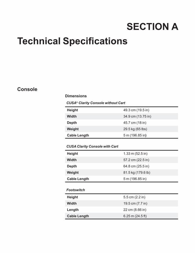
Technical SpecificationsSECTION A
Console
CUSA® Clarity Console without Cart
Height 49.3 cm (19.5 in)
Width 34.9 cm (13.75 in)
Depth 45.7 cm (18 in)
Weight 29.5 kg (65 lbs)
Cable Length 5 m (196.85 in)
CUSA Clarity Console with Cart
Height 1.33 m (52.5 in)
Width 57.2 cm (22.5 in)
Depth 64.8 cm (25.5 in)
Weight 81.5 kg (179.6 lb)
Cable Length 5 m (196.85 in)
Footswitch
Height 5.5 cm (2.2 in)
Width 19.5 cm (7.7 in)
Length 22 cm (8.66 in)
Cable Length 6.25 m (24.5 ft)
Dimensions
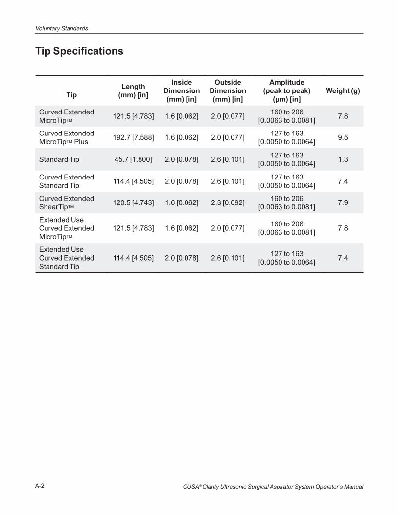
CUSA® Clarity Ultrasonic Surgical Aspirator System Operator’s ManualA-2
Voluntary Standards
Tip
Length (mm) [in]
Inside Dimension (mm) [in]
OutsideDimension(mm) [in]
Amplitude (peak to peak)
(µm) [in]Weight (g)
Curved Extended MicroTipTM
121.5 [4.783] 1.6 [0.062] 2.0 [0.077] 160 to 206 [0.0063 to 0.0081] 7.8
Curved Extended MicroTipTM Plus 192.7 [7.588] 1.6 [0.062] 2.0 [0.077] 127 to 163
[0.0050 to 0.0064] 9.5
Standard Tip 45.7 [1.800] 2.0 [0.078] 2.6 [0.101] 127 to 163 [0.0050 to 0.0064] 1.3
Curved Extended Standard Tip 114.4 [4.505] 2.0 [0.078] 2.6 [0.101] 127 to 163
[0.0050 to 0.0064] 7.4
Curved Extended ShearTipTM
120.5 [4.743] 1.6 [0.062] 2.3 [0.092] 160 to 206 [0.0063 to 0.0081] 7.9
Extended Use Curved Extended MicroTipTM
121.5 [4.783] 1.6 [0.062] 2.0 [0.077] 160 to 206 [0.0063 to 0.0081] 7.8
Extended Use Curved Extended Standard Tip
114.4 [4.505] 2.0 [0.078] 2.6 [0.101] 127 to 163 [0.0050 to 0.0064] 7.4
Tip Specifications
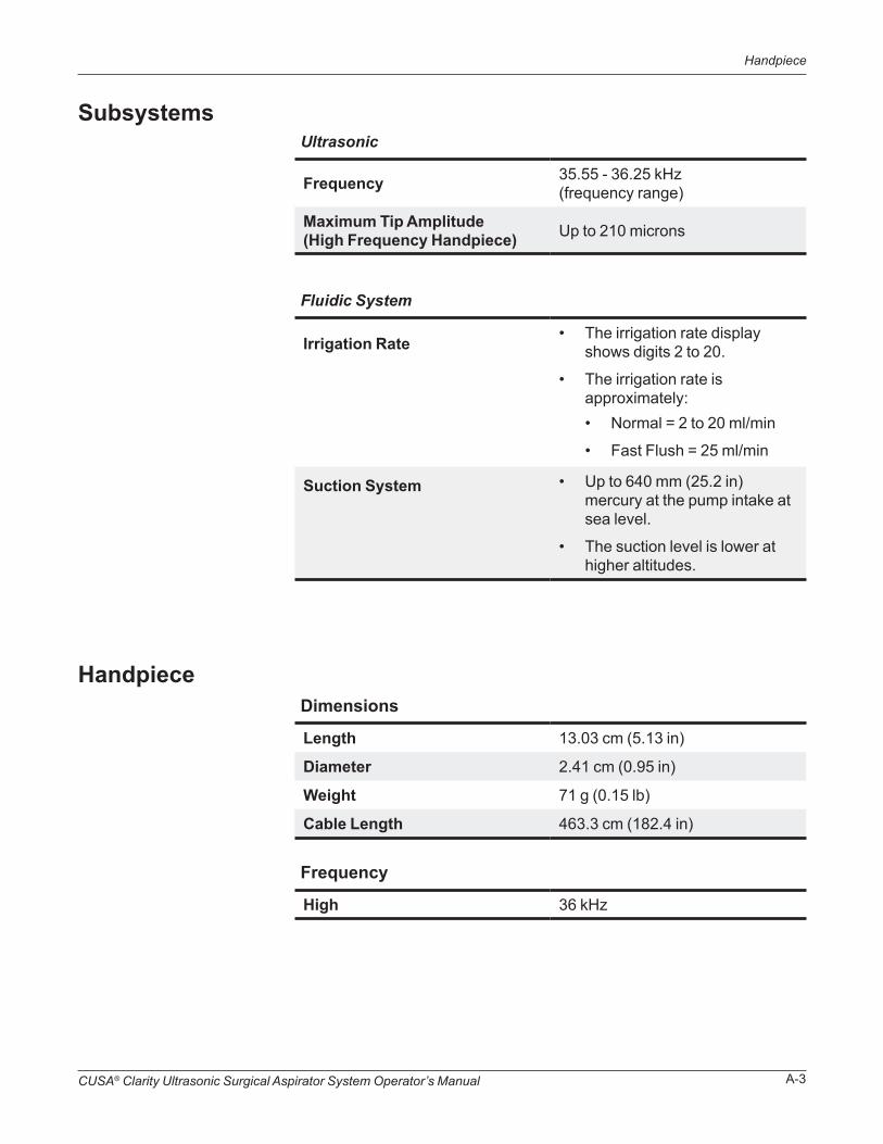
CUSA® Clarity Ultrasonic Surgical Aspirator System Operator’s Manual A-3
Handpiece
Ultrasonic
Frequency 35.55 - 36.25 kHz (frequency range)
Maximum Tip Amplitude (High Frequency Handpiece) Up to 210 microns
Fluidic System
Irrigation Rate • The irrigation rate display shows digits 2 to 20.
• The irrigation rate is approximately:
Suction System • Up to 640 mm (25.2 in) mercury at the pump intake at sea level.
• The suction level is lower at higher altitudes.
Dimensions
Length 13.03 cm (5.13 in)
Diameter 2.41 cm (0.95 in)
Weight 71 g (0.15 lb)
Cable Length 463.3 cm (182.4 in)
Frequency
High 36 kHz
Handpiece
Subsystems
• Normal = 2 to 20 ml/min
• Fast Flush = 25 ml/min

CUSA® Clarity Ultrasonic Surgical Aspirator System Operator’s ManualA-4
Electrical Requirements
Electrical Requirements
Power Cords
Power Input and Fusing
Voltage 100-240V~
Frequency 50-60Hz
Power 480VA
Phases 1
Class 1
Fuses 5A, Type T, 1500A IR, 250V, 5mm x 20mm, ceramic body
Plug variation by country:
Australia AS3112, Straight
Brazil NBR 14136, Straight
China GB2099, Straight
Europe CEE 7/ XVII, Straight
Italy CEI 23-50, Straight
Japan JIS 8303, Straight
South Africa SANS 164-1, Straight
Switzerland SEV Typ 12, Straight
United Kingdom BS 1363, 13A fused, Angled
Only use Integra approved power cords.
United States and Canada:
Meets hospital grade UL817
Cord 3 x 16AWG 5 Meters Color White
Console Connector C13 IEC 60320-1 V-Lock
Plug NIMA 5-15 Straight
Other Countries:
Cord 3 x 1mm2 5 Meters Color Black
Console Connector C13 IEC 60320-1 V-Lock
NOTEOnly the exact fuse type and rating is to be used. Littelfuse 0215005.HXP, 2 fuses required per console.

CUSA® Clarity Ultrasonic Surgical Aspirator System Operator’s Manual A-5
WARNINGExplosion Hazard - Do not use the CUSA Clarity System in the presence of flammable anesthetics or other volatile solvents.
WARNINGTo avoid risk of electric shock, this equipment must only be connected to a supply mains with protective earth.
Environment
NOTEOther devices in the operating room may generate electromagnetic interference. Use caution in locating equipment within the room to reduce the electromagnetic interference.
Maximum Low Frequency Leakage
Touch current <500µA
Patient leakage current <50µA
Under maximum loading conditions, the CUSA Clarity console is suitable for ultrasonics activation times of 10 minutes on, 5 minutes off.
The system requires a minimum of one hour exposure at its operating temperature range before you use it.
See the EMC Information section, page A-6 for further information on environmental conditions.
Electromagnetic InterferenceThe CUSA Clarity system console minimizes electromagnetic interference to other equipment used in the operating room. The system complies with the requirements of IEC 60601-1-2: 2014 Fourth Edition.
Duty Cycle
Environment
OperatingTemperature range 10°C (50°F) to 35°C (95°F)
Humidity range 30 to 85%, relative humidity, non-condensing
Atmospheric pressure range 70 kPa to 106 kPa (10.15 to 15.38 psi)
MoistureConsole Ingress Protection Rating IPX1
Storage and ShippingTemperature range -20°C (-4°F) to 60°C (140°F)
Humidity range 15 to 85% relative humidity, non-condensing

CUSA® Clarity Ultrasonic Surgical Aspirator System Operator’s ManualA-6
Voluantary Standards
NOTEThe CUSA Clarity system should not be used adjacent to or stacked with equipment other than the equipment specified in the CUSA Clarity Ultrasonic Surgical Aspirator System Operator’s Manual. If adjacent or stacked use is necessary, the CUSA Clarity system should be observed to verify normal operation in the configuration in which it will be used.
The use of accessories, other than the accessories specified in this manual, may result in increased emissions or decreased immunity of the CUSA Clarity system.
The CUSA Clarity system meets the following standards:
• IEC 60601-1:2005 +CORR. 1:2006 + CORR.2:2007 + AM1:2012 Medical Electrical Equipment Part 1: General Requirements for Basic Safety and Essential Performance, Third Edition Amendment 1
• ANSI/AAMI ES60601-1:2012 Medical Electrical Equipment Part 1: General Requirements for Basic Safety and Essential Performance
• CSA C22.2 No. 60601-1:2012 Medical Electrical Equipment Part 1: General Requirements for Basic Safety and Essential Performance
• IEC 60601-1-6:2010+AMD1:2013 Medical Electrical Equipment - Part 1-6: General requirements for basic safety and essential performance - Collateral Standard: Usability
• IEC 60601-1-8:2006+AMD1:2012 Collateral Standard - General requirements for alarm systems in Medical Electrical Equipment
• EN 60601-1-2:2007 and IEC 60601-2:2007 (3rd edition) Collateral Standard Electromagnetic Compatibility Medical Electrical Equipment
• IEC 60601-1-2:2014 (4th edition) Collateral Standard Electromagnetic Compatibility Medical Electrical Equipment
Statutory and Regulatory Classification• Class II (FDA) Medical Device (General Controls and Special
Controls)
• Class IIb (EU)
• Class III (EU)
• Class 4 (Canada)
EMC Information
Voluntary Standards

CUSA® Clarity Ultrasonic Surgical Aspirator System Operator’s Manual A-7
Voluntary Standards
Guidance and Manufacturer’s DeclarationsGuidance and Manufacturer’s Declaration – Electromagnetic Emissions
The CUSA Clarity system is intended for use in the electromagnetic environment specified below. The customer or the user of the CUSA Clarity system should assure that it is used in such an environment.
Emissions test Compliance Electromagnetic Environment - Guidance
RF emissions
CISPR 11Group 1
The CUSA Clarity system uses RF energy only for its internal function. Therefore, its RF emissions are very low and are not likely to cause any interference in nearby electronic equipment.
RF emissions
CISPR 11Class A The CUSA Clarity system is suitable for use in a
hospital environment.
Harmonics emissions
IEC 61000-3-2Not Applicable
Not applicable for hospital environmentsVoltage fluctuations / flicker emissions
IEC 61000-3-3
Not Applicable

CUSA® Clarity Ultrasonic Surgical Aspirator System Operator’s ManualA-8
Voluntary Standards
Guidance and Manufacturer’s Declaration – Electromagnetic Immunity
The CUSA Clarity system is intended for use in the electromagnetic environment specified below. The customer or the user of the CUSA Clarity system should assure that it is used in such an environment.
IMMUNITY Test IEC 60601-1-2 Test Level Compliance Level Electromagnetic Environment
- Guidance
Electrostatic discharge (ESD)
IEC 61000-4-2
± 6 kV contact (3rd ed.) ± 8 kV contact (4th ed.)
± 8 kV air (3rd ed.)
± 15 kV contact (4th ed.)
± 8 kV contact
± 15 kV air
Floors should be wood, concrete or ceramic tile. If floors are covered with synthetic material, the relative humidity should be at least 30%.
Electrical fast transient/burst
IEC 61000-4-4
± 2 kV for power supply lines
± 1 kV for input /
output lines
± 2 kV for power supply lines
± 1 kV for input /
output lines
Mains power quality should be that of a typical hospital environment.
Surge
IEC 61000-4-5
± 1 kV line(s) to line(s)
± 2 kV line(s) to earth
± 1 kV line(s) to line(s)
± 2 kV line(s) to earth
Mains power quality should be that of a typical hospital environment.
Voltage dips, short interruptions and voltage variations on power supply
input lines.
IEC 61000-4-11
< 5% UT (> 95% dip in UT)
for 0,5 cycle
< 40 % UT (> 60% dip in UT)
for 5 cycles
< 70 % UT (> 30% dip in UT)
for 25 cycles
< 5% UT (> 95% dip in UT)
for 5 s
< 5% UT (> 95% dip in UT)
for 0,5 cycle
< 40% UT (> 60% dip in UT)
for 5 cycles
<70% UT (> 30% dip in UT)
for 25 cycles
< 5% UT (> 95% dip in UT)
for 5 s
Mains power quality should be that of a typical hospital environment. If the user of the CUSA Clarity system requires continued operation during power mains interruptions, it is recommended that the CUSA Clarity system be powered from an uninterruptible power supply.
Power frequency (50/60 Hz)
magnetic field
IEC 61000-4-8
3 A/m (3rd ed.)
30 A/m (4th ed.)30 A/m
Power frequency magnetic fields should be at levels characteristic of a typical location in a typical hospital environment.
NOTE: UT is the a.c. mains voltage prior to application of the test level.

CUSA® Clarity Ultrasonic Surgical Aspirator System Operator’s Manual A-9
Voluntary Standards
Guidance and Manufacturer’s Declaration – Electromagnetic Immunity
The CUSA Clarity system is intended for use in the electromagnetic environment specified below. The customer or the user of the CUSA Clarity system should assure that it is used in such an environment.
IMMUNITY Test IEC 60601 Test Level Compliance Level Electromagnetic Environment -
Guidance
Conducted RF Immunity
IEC 61000-4-6
Radiated RF Immunity
IEC 61000-4-3
3 Vrms
150 kHz to 80 MHz (3rd and 4th ed.)
6 Vrms in ISM and amateur radio bands (4th ed.)
3 V/m
80 MHz to 2.5 GHz (3rd ed.)
80 MHz to 2.7 GHz (4th ed.)
3 Vrms
150 kHz to 80 MHz
6 Vrms in ISM and amateur
radio bands
3 V/m
80 MHz to 2.7 GHz
Portable and mobile RF communications equipment should be used no closer to any part of the system, including cables, than the recommended separation distance calculated from the equation applicable to the frequency of the transmitter.
Recommended separation distance
80 MHz to 800 MHz
800 MHz to 2.7 GHz
Where P is the maximum output power rating of the transmitter in watts (W) according to the transmitter manufacturer and d is the recommended separation distance in meters (m).
Field strengths from fixed RF transmitters, as determined by an electromagnetic site surveya, should be less than the compliance level in each frequency rangeb.
Interference may occur in the vicinity of equipment marked with the following symbol:
NOTE: At 80 MHz and 800 MHz, the higher frequency range applies.
NOTE: These guidelines may not apply in all situations. Electromagnetic propagation is affected by absorption and reflection from structures, objects, and people.
d =1,2P
d =1,2P
d =2,4P
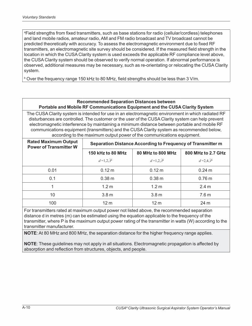
CUSA® Clarity Ultrasonic Surgical Aspirator System Operator’s ManualA-10
Voluntary Standards
aField strengths from fixed transmitters, such as base stations for radio (cellular/cordless) telephones and land mobile radios, amateur radio, AM and FM radio broadcast and TV broadcast cannot be predicted theoretically with accuracy. To assess the electromagnetic environment due to fixed RF transmitters, an electromagnetic site survey should be considered. If the measured field strength in the location in which the CUSA Clarity system is used exceeds the applicable RF compliance level above, the CUSA Clarity system should be observed to verify normal operation. If abnormal performance is observed, additional measures may be necessary, such as re-orientating or relocating the CUSA Clarity system.b Over the frequency range 150 kHz to 80 MHz, field strengths should be less than 3 V/m.
Recommended Separation Distances between Portable and Mobile RF Communications Equipment and the CUSA Clarity System
The CUSA Clarity system is intended for use in an electromagnetic environment in which radiated RF disturbances are controlled. The customer or the user of the CUSA Clarity system can help prevent electromagnetic interference by maintaining a minimum distance between portable and mobile RF communications equipment (transmitters) and the CUSA Clarity system as recommended below,
according to the maximum output power of the communications equipment.Rated Maximum Output Power of Transmitter W
Separation Distance According to Frequency of Transmitter m
150 kHz to 80 MHz 80 MHz to 800 MHz 800 MHz to 2.7 GHz
0.01 0.12 m 0.12 m 0.24 m
0.1 0.38 m 0.38 m 0.76 m
1 1.2 m 1.2 m 2.4 m
10 3.8 m 3.8 m 7.6 m
100 12 m 12 m 24 mFor transmitters rated at maximum output power not listed above, the recommended separation distance d in metres (m) can be estimated using the equation applicable to the frequency of the transmitter, where P is the maximum output power rating of the transmitter in watts (W) according to the transmitter manufacturer.NOTE: At 80 MHz and 800 MHz, the separation distance for the higher frequency range applies. NOTE: These guidelines may not apply in all situations. Electromagnetic propagation is affected by absorption and reflection from structures, objects, and people.
d =1,2P d =1,2P d =2,4P

CUSA® Clarity Ultrasonic Surgical Aspirator System Operator’s Manual B-1
Warranty
Integra LifeSciences Corporation and its wholly owned subsidiaries (“Integra”) warrant to Integra authorized distributors and to the original purchaser only that each new Integra® CUSA® Clarity Ultrasonic Surgical Aspirator System (“CUSA Clarity”) is free from defects in materials and workmanship under normal use and service for a period of one (1) year from the date of delivery (“Warranty Period”) by Integra to the original purchaser, but in no event beyond the expiration date stated on any product labeling (hereinafter the Warranty Period). For the purpose of products sold by Integra through an Integra-authorized distributor, “original purchaser” shall mean the purchaser of Integra products to whom an Integra-authorized distributor first sells the product. The original purchaser is hereinafter referred to as Customer.
1.1. Coverage. During the Warranty Period, Integra shall provide free-of-charge service and maintenance consistent with the provisions of Section 3 of this Warranty, so that the Equipment conforms to the specifications defined in the CUSA Clarity Operator’s Manual, as such Operator’s Manuals may be modified by Integra from time to time (the “Specifications”).
1.2. Exclusions. The Warranty shall not apply in any manner to service or maintenance of the Equipment, or to replacement of its parts, with respect to:
(i) use of Equipment with any tips, flues, and cartridge and tubing sets and accessories other than those manufactured by Integra LifeSciences;
(ii) defects arising out of materials or parts provided, modified, or designed by anyone other than an authorized Integra service agent (the “Integra Service Agent”);
(iii) defects emanating from improper or negligent installation, storage, or use of the Equipment or any component thereof, including but not limited to operating the Equipment not in accordance with instructions provided in the Operator’s Manual;
(iv) defects arising from improper or negligent cleaning or sterilization methods or improper maintenance of the Equipment;
(v) defects resulting from repairs or service of the Equipment provided other than by Integra or its authorized representatives;
Warranty
WarrantySECTION B
CUSA® Clarity Ultrasonic Surgical Aspirator System Operator’s ManualB-2
Warranty
(vi) defects arising from accidental damage to the Equipment, acts of God, electrical power damage, equipment malfunction, unusual stress, unreasonable operating procedures, or abnormal or extreme operating conditions; and
(vii) normal wear and tear.
2.1 Service and Repairs. All service and repairs covered by this Warranty may be referred to hereinafter as “in-warranty repairs,” and all service and repairs not covered by this Warranty may be referred to as “out-of-warranty repairs.” Integra’s sole obligation for in-warranty repairs shall be to make all necessary adjustments and repairs in accordance with this Warranty. Integra shall charge Customer at Integra’s then-standard rates for any out-of-warranty repair performed by Integra.
2.2 Equipment Replacement. The defective Equipment or part thereof that is replaced in accordance with the Warranty shall be the property of Integra. Integra reserves the right to fill spare parts requests using refurbished sub-assemblies provided that such sub-assemblies are functionally equivalent to new sub-assemblies and carry the same warranty as the replaced sub-assemblies.
2.3 Notification. In order to avail itself of its rights under the Warranty, Customer or Integra authorized distributors, must immediately notify Integra of any defects and provide Integra every opportunity to inspect and remedy defects.
3. 1 Included under the Warranty are the following services:
3.1.1 Consoles. Integra or its distributor, when authorized for this purpose, shall, if possible, perform on-site repair of consoles and where not possible or otherwise decided at the sole discretion of Integra, Integra or its distributor shall arrange and pay to ship the affected Equipment to the designated repair facility. Integra or its distributor authorized for this purpose shall repair the affected Equipment or replace a console by a new or refurbished console (at the discretion of Integra), that shall carry the same remaining warranty as the original equipment.
3.1.2 Handpieces. Integra shall repair or replace any defective handpieces covered by the Warranty by a new or refurbished handpiece (at the discretion of Integra) that shall carry the same remaining warranty as the original equipment.
Service, Repairs and Replacement
Repair Parts and Services

CUSA® Clarity Ultrasonic Surgical Aspirator System Operator’s Manual B-3
Warranty
Quality Control
Limitation of Liability
3.2 Modifications to Covered Equipment. From time to time, at its sole discretion, Integra may propose modifications to the covered Equipment and to the Specifications for the Equipment. Subject to Customer’s approval and at its sole expense, the Customer may request Integra to make such modifications to the covered Equipment and to the Specifications. Integra shall make such modifications for the Customer, which modifications may include the installation of new parts in the Equipment, at a price equal to the then-current list price for such modifications, as such list price is established by Integra in its sole discretion.
4. 1 Customer shall maintain reasonable standards of quality control, operations, procedures, safety testing and inspection of Equipment to ensure that unnecessary service or maintenance is not required hereunder.
4. 2 Customer shall provide a technical counterpart to Integra’s Service Agent for assistance in Integra’s telephonic diagnosis of the malfunction with the Equipment. Customer shall reasonably accept Integra’s determination whether a repair or service is an in-warranty repair or an out-of-warranty repair.
5. 1 Integra’s only responsibility under the warranties described in Section 1 shall be repair or replacement, at Integra’s option and election, of any Integra product (or part thereof) that Integra reasonably determines to be covered by this warranty and to be defective in workmanship or materials. Repair or replacement of products under this warranty does not extend the warranty period.
THE WARRANTIES DESCRIBED IN SECTION 1 HEREOF ARE EXCLUSIVE AND ARE GIVEN AND ACCEPTED IN LIEU OF ALL OTHER WARRANTIES OF INTEGRA OR ITS SERVICE AGENTS WITH RESPECT TO THE QUALITY, PERFORMANCE AND OPERATION OF THE EQUIPMENT, WRITTEN OR ORAL, EXPRESSED OR IMPLIED, AND WHETHER OR NOT ATTRIBUTABLE TO SERVICE PERFORMED PURSUANT TO THE WARRANTY. INTEGRA DISCLAIMS ALL OTHER WARRANTIES, EXPRESS OR IMPLIED, WITH RESPECT TO THE EQUIPMENT OR THE SERVICES, DIAGNOSES, ADVICE, ASSISTANCE OR PARTS TO BE TENDERED PURSUANT TO THE WARRANTY, INCLUDING, BUT NOT LIMITED TO, IMPLIED WARRANTIES OF MERCHANTABILITY AND FITNESS FOR A PARTICULAR PURPOSE, AND ANY IMPLIED WARRANTY ARISING FROM COURSE OF PERFORMANCE, COURSE OF DEALING, USAGE OR TRADE OR OTHERWISE, OR APPLIACTION OR WARRANTY OF QUALITY AS WELL AS ANY EXPRESS OR IMPLIED WARRANTY TO PATIENTS.

CUSA® Clarity Ultrasonic Surgical Aspirator System Operator’s ManualB-4
Warranty
Further, this warranty shall not apply to, and Integra shall not be responsible for, any loss arising in connection with the purchase or use of any Integra product that has been repaired by anyone other than an authorized Integra service representative or altered in any way so as, in Integra’s sole judgment, to affect its stability or reliability, or which has been subject to misuse, negligence or accident, or which has been used other than in accordance with the instructions furnished by Integra.
IN NO EVENT SHALL INTEGRA, ITS AFFILIATES, ASSIGNEES OR SERVICE AGENTS BE LIABLE FOR ANY INCIDENTAL, INDIRECT, CONSEQUENTIAL, SPECIAL OR PUNITIVE DAMAGES IN CONNECTION WITH THE ACQUISITION OR USE OF ANY INTEGRA PRODUCT, OR OF LOSS OF USE, REVENUE OR PROFIT, WHETHER ARISING IN CONTRACT OR IN TORT, BY VIRTUE OF THE WARRANTY OR ANY PERFORMANCE OR BREACH BY INTEGRA, ITS AFFILIATES, ASSIGNEES OR SERVICE AGENTS HEREUNDER OR PURSUANT HERETO.
5. 2 Customer agrees that, notwithstanding the technical assistance provided pursuant to the Warranty by Integra or its representatives, Customer shall be fully responsible for all treatments performed or attempted with the Equipment.
INTEGRA MAKES NO REPRESENTATION OR WARRANTY AS TO THE EFFICACY OF THE EQUIPMENT OR OF THE TECHNICAL ASSISTANCE TO BE RENDERED BY INTEGRA, ITS AFFILIATES, ASSIGNEES OR SERVICE AGENTS, FOR PURPOSES OF THE PARTICULAR TREATMENT THAT CUSTOMER UNDERTAKES TO PERFORM FOR THIRD PARTIES. Moreover, Customer shall not make any claim against Integra or any of its affiliates, assignees or representatives with respect to the efficacy of the Equipment or of said technical assistance or with respect to any claims by third parties related to any treatment undertaken by Customer.
5. 3 Force Majeure. Notwithstanding anything to the contrary herein contained, if the performance of the Warranty by Integra or Customer or any obligation of Integra or Customer hereunder is prevented, restricted or interfered with by reason of fire, explosion, act of God, labor disputes or accidents affecting performance under the Warranty, or war, mobilization, civil commotions, blockade or embargo, or any future law, regulation, ordinance or requirement of any government or regulatory agency or any other act, whatsoever similar to those above enumerated, or any other circumstance being beyond the reasonable control of Integra or Customer, then and in that event Integra or Customer, as the case may be, shall promptly notify the other party hereto of the resulting difficulties therefrom, and any of the foregoing events shall excuse any performance required under the Warranty.