Embed Size (px)
Citation preview
Rev 4
LEngineering StandardES -002 ]
Instrument Error Calculation andSetpoint Determination
This standard addresses:
/ A uniform method for establishing setpoints forinstrumentation channels; factors that must beconsidered when establishing instrument setpointsand how these factors are combined.
Approved By: I ' A -dDate: a/ 16 tJ_% C)
Originator Electrical Engineering InstrumentationThis Document. is within OQA Plan Scope
Design Verification Required
Nuclear Technical Functions Division
TABLE OF CONTENTS
1.0 PU RPOSE & SCOPE ................................................
2.0 APPLICABILITY ..................................................
3.0 REEE NEJE .....................................................
4.0 EFTNl moNs .................................. ...................
5.0 RE9MREMEN EST... ................................................5.1 Deternination of Setpoints ......................................5.2 Allowable Value (Technical Specification Limit)......................
3
3
3
3
666
6.0 CATLCTUIATTONS....................................6.1 Instrument Accuracy Baseline Data .................62 Combining Accuracy Errors .......................6.3 Discussion of Accuracy Calculations ................
[1] Process Measurement ......................[2] Static Pressure Errors ......................[3] Nornal Accurac .........................[4] Accident Accuracy ........................[5) Time Response ...........................
.........
.... ... ..
....... ..
.........
999
101010101113
14
...............
...............
...............
SUMMARY OF CHANGE ................... ;
Page 2 of 14
GF'U Nuclear
011/031
Instrument Error Calculation andSetpoint Determination
(ES-00; Rev 4)
��M
1.0 PURPOSE & SCOPE
This design standard describes a uniform method for establishing setpoints forinstrumentation channels. Setpoints are intended to initiate corrective or protective actionsin a timely manner before the safety of people and/or equipment are endangered.Therefore, those factors that influence the accuracy of the instruments initiating the setpointfunction must be considered to assure that the instrument trip signal will be generated whenit is required. This standard addresses the factors that must be considered whenestablishing an instrument setpoint and how these factors are combined. Included are therelationships of the instrument setpoint to the various limits of normal operation, designbasis event environmental conditions, and calibration and surveillance testing. The: scopeof this standard does not include the methods for determining equipment protective values,process safety limits, safety factors that should be utilized, or design basis event analysis thatapply. Factors affecting instrument accuracy are described, along with methods forcalculating their impact on overall loop accuracy, and setpoint.
2.0 APPLICABILITY
This standard shall apply to new designs, modifications of design, and for new calculationsrequired for safety system instruments with setpoints where specific actions are eitherinitiated, terminated or prohibited. The methods in this standard shall apply to both safetyrelated and Balance of Plant (BOP) calculations.
Error calculations that utilize this standard shall address every item in the RequirementsSection 5.0. If a requirement of this standard is evaluated as not applicable, then thecalculation shall provide a statement of the reasons why it is not included.
3.0 REFERENCES
3.1 ISA-S51.1 (1979) Process Instrument Terminology.
3.2 ISA-S67.04 (1982) Setpoints for Nuclear Safety-Related Instrumentation Used In NuclearPower Plants.
3.3 Regulatory Guide 1.105 revision 2 (February 1986) Instrumentation Setpoints forSafety-Related Systems.
3.4 NUREG/CR-3691 (September 1984) An Assessment of Terminal Blocks in the NuclearPower Industry.
4.0 DEFINMONS
4.1 Agoragy - In process instrumentation, degree of conformity of an indicated value to arecognized accepted standard value, or ideal value (Ref. 1).
Page 3 of 14
GPU Nuclear Instrument En-or Calculation and (ES-002 Rev 4)Setpoint Determination
011,1)31
��M
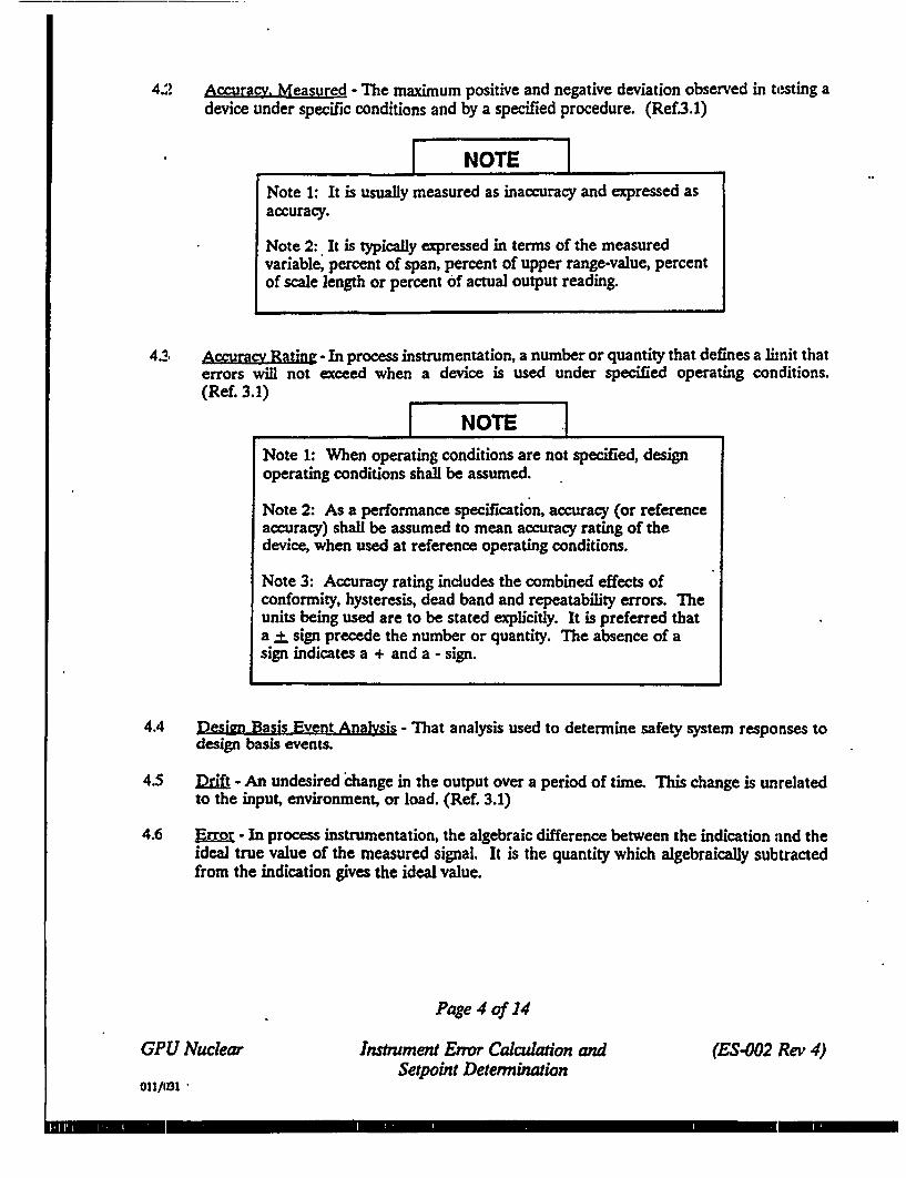
4.2 Accuracy. Measured - The maximum positive and negative deviation observed in testing adevice under specific conditions and by a specified procedure. (Ref3.1)
t
I NOTE INote 1: It is usually measured as inaccuracy and expressed asaccuracy.
Note 2: It is typically expressed in terms of the measuredvariable, percent of span, percent of upper range-value, percentof scale length or percent of actual output reading.
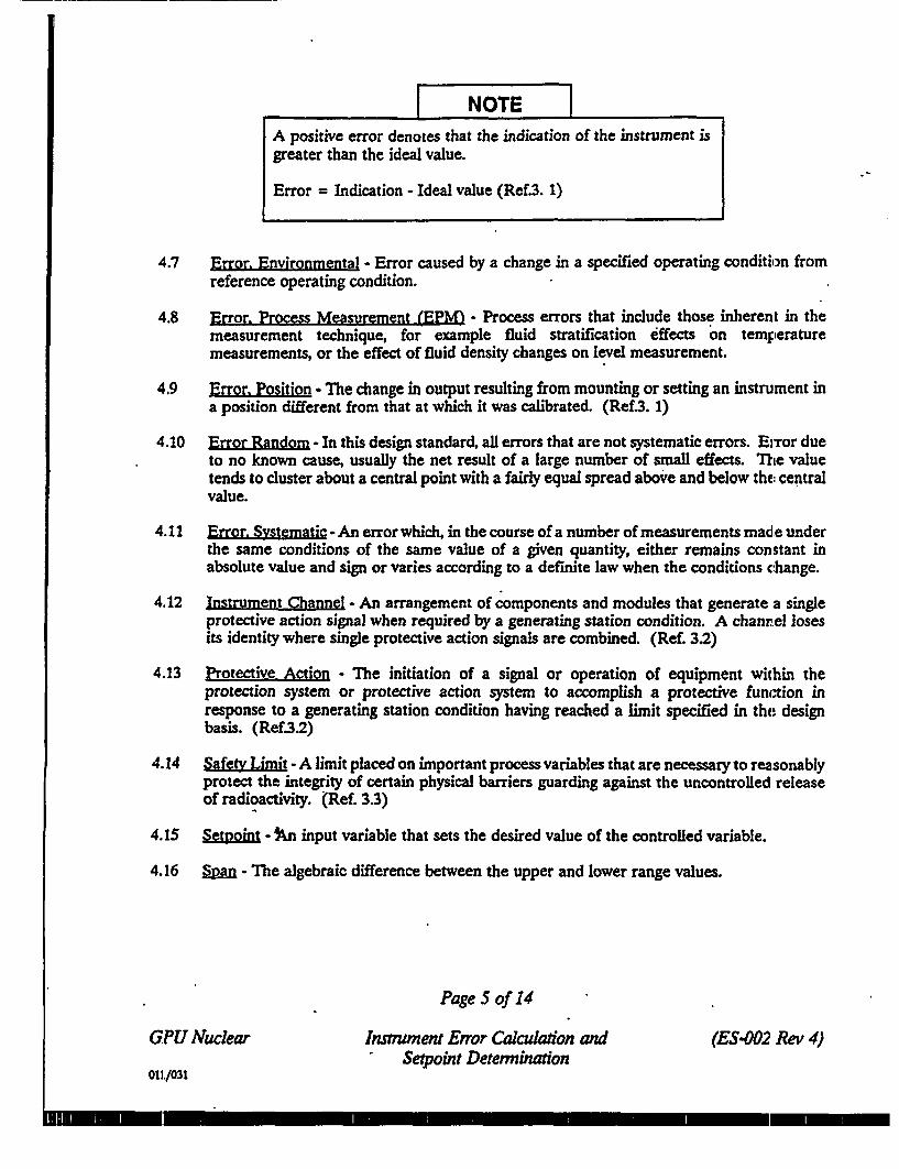
42at Accurac Rating - In process instrumentation, a number or quantity that defines a limnit thaterrors will not exceed when a device is used under specified operating conditions.(Ref. 3.1) t _
I NOTE .1Note 1: When operating conditions are not specified, designoperating conditions shall be assumed.
Note 2: As a performance specification, accuracy (or referenceaccuracy) shall be assumed to mean accuracy rating of thedevice, when used at reference operating conditions.
Note 3: Accuracy rating includes the combined effects ofconformity, hysteresis, dead band and repeatability errors. Theunits being used are to be stated explicitly. It is preferred thata + sign precede the number or quantity. The absence of asign indicates a + and a - sign.
4.4 Design Basis Event Analysis - That analysis used to determine safety system responses todesign basis events.
4.5 fdft - An undesired diange in the output over a period of time. This change is unrelatedto the input, environment, or load. (Ref. 3.1)
4.6 Error - In process instrumentation, the algebraic difference between the indication and theideal true value of the measured signal. It is the quantity which algebraically subtractedfrom the indication gives the ideal value.
Page 4 of 14
GPU Nuclear
01/1(1 -
Instrument Error Calculaion andSetpoint Determination
(ES-002 Rev 4)
I1__
I II NOTE I
A positive error denotes that the indication of the instrument isgreater than the ideal value.
Error = Indication - Ideal value (Ref3. 1)
4.7 Error. Environmental - Error caused by a change in a specified operating condition fromreference operating condition.
4.8 Error. Process Measurement (EPM' - Process errors that include those inherent in themeasurement technique, for example fluid stratification effects on temperaturemeasurements, or the effect of fluid density changes on level measurement.
4.9 Error. Position -The change in output resulting from mounting or setting an instrument ina position different from that at which it was calibrated. (Ref3. 1)
4.10 r[or Random - In this design standard, all errors that are not systematic errors. Error dueto no known cause, usually the net result of a large number of small effects. The valuetends to cluster about a central point with a fairly equal spread above and below the: centralvalue.
4.11 Error, Systematic - An error which, in the course of a number of measurements made underthe same conditions of the same value of a given quantity, either remains constant inabsolute value and sign or varies according to a definite law when the conditions change.
4.12 Instrument Channel - An arrangement of components and modules that generate a singleprotective action signal when required by a generating station condition. A channel losesits identity where single protective action signals are combined. (Ref. 3.2)
4.13 Protective Action - The initiation of a signal or operation of equipment within theprotection system or protective action system to accomplish a protective function inresponse to a generating station condition having reached a limit specified in the designbasis. (Ref3.2)
4.14 Safety Limi -A limit placed on important process variables that are necessary to reasonablyprotect the integrity of certain physical barriers guarding against the uncontrolled releaseof radioactivity. (Ref. 3.3)
4.15 Setnoint - Pn input variable that sets the desired value of the controlled variable.
4.16 Span - The algebraic difference between the upper and lower range values.
Page 5 of 14
GPU Nuclear Imntument Error Calculadon and (ES.002 Rev 4)Setpoint Detenninadon
011/031
I-

5.0 REQUIREMENTS
5.1 Determination of Setpoints
Setpoints shall be selected to provide sufficient margin between the protective action setpointand the system protection limits to account for all the inaccuracy inherent in the instrumentloop. This inaccuracy may be due to instrument inaccuracy, loop calibration tolerance,inaccuracy of the test equipment, process measurement inaccuracy, effects of transientovershoot, effects of time response characteristics, environmental effects, instrument drift,or the effects of normal process transients/upsets. Detailed requirements for the instrumentsetpoint relationships are delineated in this section and illustrated by Figure 1.
5.2 Allowable Value (Technical Specification I~mlt)
The technical specification limit shall be regarded as the operational allowable value.Operation within the allowable value shall provide assurance that automatic protective actionwill correct the most severe abnormal situation anticipated before a safety limit is exceeded.
(1] The allowances between the allowable value (technical specification limit) and thesafety limit shall include the following items unless they are included in thedetermination of the process safety limit.
a. The effects of potential transient overshoot as determined by the design basis eventanalysis.
b. The effects of the time response characteristics of the total instrument channel,including the sensor.
c. Environmental effects on instrument accuracy or time response characteristics causedby anticipated operational occurrences or design basis events for those instrumentsrequired to mitigate the consequences of such events.
[2]. Setpoints and Technical Specification Allowable Limits
The setpoint value to initiate protective action, combined with the instrument loopinaccuracies at normal operating conditions, shall not exceed the Allowable Value(Technical Specification Limit). This margin between setpoint and allowable, valuesshall provide allowance for:
a. The tolerance specified in the instrument loop calibration procedure, This value isconsidered a systematic error for conservatism.
b. All instrument random and systematic inaccuracies and drift that occur during normalenvironmental operating conditions.
c. Accuracy of the test equipment used for surveillance testing the instrument channel.
d. Process measurement accuracy such as the effects of fluid stratification and changingfluid density.
Page 6 of 14
GPU Nuclear Instrument Eror Calculation and (ES-002 Rev 4)Setpoint Determination
011/031
3] Setpoints and Operational Limits
Referring to Figure 1, the normal desired operation reference line represents thenominal value the operator desires for the process. This nominal value of the processvaries slightly with operational transients that are in an acceptable range to theoperator and this is represented by the Operational Limit reference line. Theinstrument trip setpoint specified must provide sufficient margin to assure thatinaccuracy and normal drift of the instruments do not cause the instrument to trip onprocess values within its Operational Limit.
[4] Setpoint Upper/Lower Limits (As Left Calibration Tolerance)
This is the tolerance specified in the surveillance test procedure that is acceptablewithout recalibration. The band between the setpoint and its upper or lower limitshall be broad enough to minimize the need for frequent instrument adjustment. Thesetpoint upper and lower limit (calibration tolerance) specified on the test proceduremay be derived from historical maintenance data or other engineering sources. Fornew designs, the test tolerance shall be calculated to include the statisticalcombination of the two sigma random accuracy ratings of all the instruments thatcomprise the loop, and the accuracy ratings of the test equipment used to calibratethose instruments. This value is expressed with a plus and minus sign that defines theupper and lower setpoint limits. For new designs, the setpoint is determined by*algebraically adding the calibration procedure tolerance to the calculated loop error.This is very conservative. Historical performance of the instrument loop may permita reduction in this conservatism and subsequent setpoint readjustment.
[5] Acceptable-as-Found Limit
The Acceptable-as-Found limit also known as the surveillance test Acceptance Criteriaat TMI-1, shall be used for the evaluation of surveillance test as-found data.. Thisband defines acceptable drift limits of the instruments included in the surveillance test,and is used to confirm that the instrument loop has not drifted beyond an acceptablepredicted value.
As-found limit shall include errors due to drift, temperature effect, and power supplyeffect in addition to those errors used to determine the upper/lower set point limit.
For some existing instrument loops at TMI-1 the surveillance test Acceptance Criteria(acceptable as found limit) is the same value as the setpoint upper/lower limi t value.For these instrument loops the values were either derived from historical instrumentperformance data, or were specified by the manufacturer that provided the instrumentloop.
Errors that are not measurable during a surveillance test are not included in theAcceptable-as-found limit. (e.g. Transmitter error when the transmitter is not part ofthe surveillance test.)
Page 7 of 14
GI'U Nuclear Instrument Error Calculation and (ES-002 .Rev 4)Setpoint Determination
011/031

Instrument Setpoint Relationship
This figure provides relative positiononly and is not intended to iply direction.
SAFETY LIMfIT I _ _ _ __ _ _ _
I besign Basis Event Analytic
I Safety Fsctoe
PROCESS SAFETY LIMIT
U iranslent Overshoot
Acident Environmental Effects en
Instff"lt Accuracy
Any Error PAttr Not Included SalowTime Response characteristics
See Section 5.2
See Section 5.2t53
See Section 5.2141
ALLOVABLE LININ (TEO0iCAL SPECIFICATION LIMIT)
* Proc.. Neaswreant Accuracy
* Znetrnent Accurac of Any
CoUp"*"% Not In TestAccuracy Tst Equipment Wsed In
Surveill aee Test
ACCEPTABLE-AS^FO i
* Accuracy ratin of Instrumefnt Tested
3 leperatur Error EffectI Power Supply Error Effect
a Drift of Instrwments Tested
UPPER SETPOI11 LIMIT
Tolerance allowed for setpoint by
ca lbration Procedures
SETPOINT
LOWER SETPOIiT LIMIT
_ .
CalibrationRequired
{ Calibration
Required
io Calibration
Required
ACCEPTABLE-AS FWUD
See Siclion 5.2131 OPERATIONAL LIMIT (DESIRED)
MAL (DESIRED OPERATION)Figure 1
II
I
Page 8 of 14
GPU Nuclear Insftument Error Calculation andSetpoim Determination
(ES-002 .Rev 4)
o1I/a31
_ _ M
-
.0 CALCULATIONS
(6.1 Instrument Accuracy Baseline Data
[1] Vendor product specifications and/or Environmental Qualification (EQ) files shallbe used to obtain accuracy data for each instrument for normal and harshenvironmental conditions. It is usual practice for instrument suppliers to expressaccuracy data as an upper limit based on test data inaccuracy values that none oftheir instruments will exceed (the confidence level is greater than 99.7%,). It isconservative to assume that the vendor accuracy data unless otherwise specified,represents a probability distribution of three sigma with a confidence level of 99.7%.
[2] For accuracy calculations the NRC staff has accepted 95.5% (two sigma value) asa probability limit for errors (Ref33). Therefore all calculations shall utilize allbaseline data of random values at two sigma to provide loop accuracy and set pointvalues at a two sigma probability.
[3] Three sigma baseline values can be converted to two sigma by multiplying bytwo-thirds.
[4] In an accuracy calculation of an instrument string of two or more componentsconvert all individual component errors into the common unit for the variable ofconcern. For example, a string consisting of a differential transmitter, an analyticalunit and a meter may have their individual accuracies expressed as % full range(psi), % of output (mv), and % of scale (ft. of water). If the variable of cotcern isft. of level, the accuracy of each component should be converted to feet of level forthe calibrated range of the application.
6.2 Combining Accuracy Errors
The accuracy error values of the instrument loop are combined using the following m ethods:
[I] All errors identified as random errors will be combined using the square root of thesum of the squares method.
[2] Systematic errors will be combined by algebraic summation.
[3] The total inaccuracy is the algebraic sum of the total random error and totalsystematic error.
Page 9 of 14
GI U Nuclear Instrument Efror Calculation and (ES-002 Rev 4)Setpoint Determination
011/031
6.3 Discussion or Accuracy Calculations
Following is a discussion of various errors to be considered.
[1] Process Measurement
Process errors in measurement are caused by process variables other than that beingmeasured. Flow and level measurements using differential pressure transmitters aresubject to errors due to changes in the temperature and the static pressure of theprocess fluid.
Temperature and pressure change influence the density of the fluid. This changesthe output of primary flow elements. It also changes the pressure produced by agiven level of fluid in a vessel or a level reference leg. Differential pressuretransmitters are calibrated to measure flow or level at a particular fluid pressure andtemperature. Any change from this condition produces an error. The error mustbe computed for the fluid pressure and temperature change of interest andexpressed as a percent of the differential pressure span to which the transmitter iscalibrated.
[2] Static Pressure Errors
Differential pressure transmitters can be calibrated to correct for the systematicerror from zero and span shifts at a particular static pressure. Any deviation fromthe calibration pressure caused by either a transient or a change in operatingconditions will produce a new error due to zero span shifts. When a differentialpressure transmitter is operated at a pressure different from the pressure :For zerosystematic error over a range of static pressures then the systematic error. shouldbe accounted for in the loop error calculation. Differential pressure transmittermanufacturers generally provide the error equations for their instruments.
Pressure instruments, absolute or gage, respond to the pressure head due to theheight difference between the point-of-interest and the pressure sensor. Include apressure head correction in both setpoint determination and accuracy calculations.
[3] Normal Accuracy
These calculations are performed taking into account normal (non-accident)conditions of humidity, temperature, etc., errors of the individual modules thatcomprise the loop considering the following
a. Module Accuracy Rating - The accuracy of the module under consideration includethe combined effects of probable error introduced as a result of dead band,repeatability, hysteresis, etc.
Page 10 of 14
GPU Nuclear Instrnment Error Calculation and (ES-002 Rev 4)Setpoint Determination
O11P)31

b. Calibration loop tolerance - This error is specified in the instrument loopsurveillance test procedure. For new designs this error is calculated by statisticallycombining the two sigma values of the accuracy ratings of all the modules thatcomprise the surveillance test loop and the accuracies of the test equipment usedduring calibration.
c. Temperature Error - This error is caused by changes in the module ambienttemperature from calibration conditions over the design range.
d. Drift * This error is caused by a change in accuracy within the design rangeconditions over a period of time.
e. Power Source - These are errors introduced as a result of fluctuations in the powersupply from calibration conditions over the designorange.
f. Test Instrument Error - This error is the accuracy of the test equipment used in thecalibration or surveillance testing of the instrument. Where the test equipmenttolerance is expressed as plus or minus % of reading a conservative (maximum)error value would be based on the upper (100%) calibrated span reading; of theinstrument.
e Calibration test equipment accuracies are used in calculating the calibration looptolerance error (63[3]b.
° Surveillance test equipment accuracies are used in calculating the total loop error(5.2.[2]c).
g. Miscellaneous Errors - Errors that may be peculiar to a particular module shouldbe included, i.e., self heating.
h. Wire Drop Errors - Errors introduced as a result of line drop, as signal currentpasses through dropping resistors, terminations, etc.
i. Radiation Exposure
[4] Accident Accuracy
a. Accident accuracy calculations are performed only for those instruments loops thathave any component physically located in a harsh environment. Only thosehumidity, temperature, and radiation errors due to the accident environment arecombined to define the Accident Accuracy.
Instruments are qualified to operate in the worst environment anticipated at itslocation. However, the accuracy calculations are performed for the intendedfunction, and may utilize environmental limits that exist when the intended functionis accomplished.
Page 11 of 14
GPU Nuclear Instrument Error Calculation and (ES-002 Rev 4)Setpoint Deteryination
011.1031
M �� __ -
b. The functional significance of the various accident errors may not be applicablewhen specific circuit functions and applications are reviewed. For instance, theinstrument may have performed its protective function before it is exposed tomaximum harsh accident environmental conditions. This is very common whenconsidering Circuit Insulation resistance error. Good practice is to identify the errorand state clearly the reasons or assumptions for not including the error in theaccident calculation.
Where maximum accident temperature and radiation errors do not occurconcurrently, perform two separate calculations and identify them by the time afterthe accident. Use the worst (greatest) error value of the two calculations to definethe Accident Accuracy.
In those instances where the instrument product data sheets or EQ test reportsprovide error values for environmental conditions much more severe than the designbasis event conditions, and the error calculations are not realistic, one of thefollowing methods may be applicable:
° Request the instrument manufacturer provide specific accuracy values at the desiredconditions and document the response with ED&CC and/or EQ files.
° Use straight line interpolation if the results will be conservative.
If the error is non-linear with the data points given, and is some unknownexponential function e, = eN, for N>O than a straight line interpolation will provideconservative error values between the extreme given values.
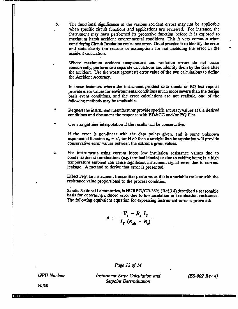
c. For instruments using current loops low insulation resistance values due tocondensation at terminations (e.g. terminal blocks) or due to cabling being irn a hightemperature ambient can cause significant instrument signal error due to currentleakage. A method to derive that error is presented:
Effectively, an instrument transmitter performs as if it is a variable resistor with theresistance value proportional to the process condition.
Sandia National Laboratories, in NUREG/CR-3691 (Ref3.4) described a reasonablebasis for determing induced error due to low insulation or termination resistance.The following equivalent equation for expressing instrument error is provided:
V -Re ITIT (Rs - R.)
Page 12 of 14
GPU Nuclear Instrument Error Calculation and (ES-002 Rev 4)Setpoint Determination
011/031

Where: e = Fractional Error of Reading
V, = Source Voltage (Volts)
R, = Equivalent Series Resistance of Loop (Ohms)
I, = Transmitter Output Current (Amps)
Et, = Insulation resistance of termination(s), cable/or splice(Including Adjustment for Length and Circuit Configuration)(Ohms)
[5] Time Rense
Time response calculations are determined by algebracially adding together theresponse time of each instrument in instrument channel. Response time is providedon the manufactures product specification. Use the absolute value provided, or thevalue required to obtain one time constant.
The time response is analyzed to insure the integrity of the protective action ismaintained by assuring that the process safety limit is not exceeded during the timerequired for the instrument channel to initiate the protective action signaL
Page 13 of 14
GIU Nuclear nstrumen Error Calculation andSetpoint Determination
(ES-002 Rev 4)
011/031
I3
=
Rev 1
Rev 2
Rev 3
Rev 4
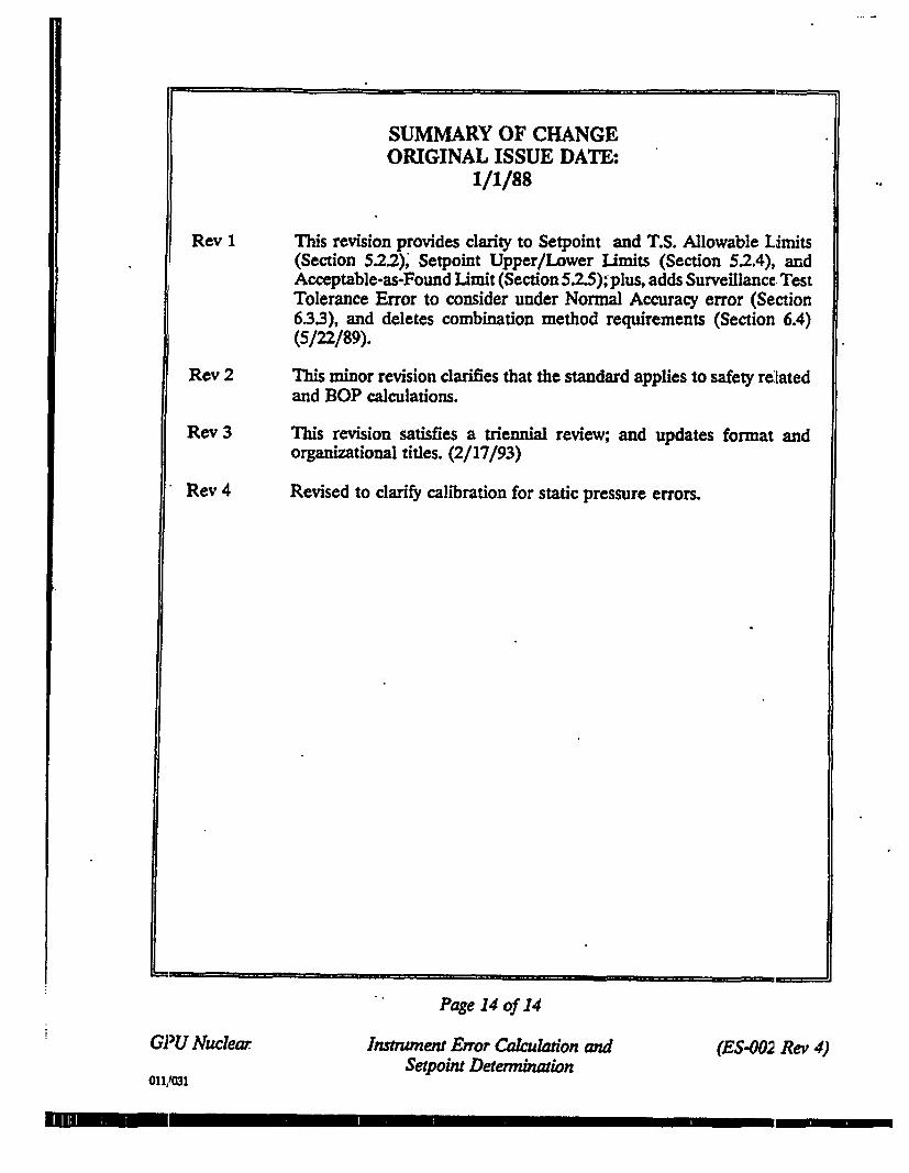
SUMMARY OF CHANGEORIGINAL ISSUE DATE:
1/1/88
This revision provides clarity to Setpoint and T.S. Allowable Limits(Section 5.2.2), Setpoint Upper/Lower Limits (Section 5.2.4), andAcceptable-as-Found Limit (Section 52.5); plus, adds Surveillance. TestTolerance Error to consider under Normal Accuracy error (Section6.33), and deletes combination method requirements (Section 6.4)(5/22/89).
This minor revision clarifies that the standard applies to safety relatedand BOP calculations.
This revision satisfies a triennial review; and updates format andorganizational titles. (2/17/93)
Revised to clarify calibration for static pressure errors.
Page 14 of 14
GPU Nuclear Instument Error Cakulation andSetpoint Detembination
(ES-002 Rev 4)
011,1031