Embed Size (px)
Citation preview
INSTRUCTIONS
CX21EDUCATION MICROSCOPE
A X 7 4 0 3
This instruction manual is for the Olympus Education Microscopes Model CX21. To ensure thesafety, obtain optimum performance and to familiarize yourself fully with the use of this microscope,we recommend that you study this manual thoroughly before operating the microscope. Retain thisinstruction manual in an easily accessible place near the work desk for future reference.

CX21
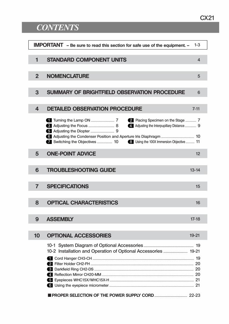
CONTENTS
4
5
6
7-11
IMPORTANT — Be sure to read this section for safe use of the equipment. —
1 STANDARD COMPONENT UNITS
2 NOMENCLATURE
3
4 DETAILED OBSERVATION PROCEDURE
SUMMARY OF BRIGHTFIELD OBSERVATION PROCEDURE
1-3
10-1 System Diagram of Optional Accessories ............................................................................ 1910-2 Installation and Operation of Optional Accessories ..................................... 19-21
1 Turning the Lamp ON ........................................... 7 3 Adjusting the Focus ................................................ 8 5 Adjusting the Diopter ............................................ 9
2 Placing Specimen on the Stage .................... 7 4 Adjusting the Interpupillary Distance ..................... 9
5 ONE-POINT ADVICE
6 TROUBLESHOOTING GUIDE
7 SPECIFICATIONS
8 OPTICAL CHARACTERISTICS
9 ASSEMBLY
10 OPTIONAL ACCESSORIES
12
13-14
15
16
17-18
19-21
1 Cord Hanger CH3-CH ............................................................................................................................................................................................ 19 2 Filter Holder CH2-FH ............................................................................................................................................................................................... 20 3 Darkfield Ring CH2-DS ........................................................................................................................................................................................ 20 4 Reflection Mirror CH20-MM .......................................................................................................................................................................... 20 5 Eyepieces WHC15X/WHC15X-H .............................................................................................................................................................................................. 21 6 Using the eyepiece micrometer ............................................................................................................................................................................................... 21
6 Adjusting the Condenser Position and Aperture Iris Diaphragm ............................................................. 10 7 Switching the Objectives ............................ 10 8 Using the 100X Immersion Objective .................... 11
PROPER SELECTION OF THE POWER SUPPLY CORD ....................................................... 22-23
1
IMPORTANT
SAFETY PRECAUTIONS
1. After the equipment has been used in an observation of a specimenthat is accompanied with a potential of infection, clean the partscoming in contact with the specimen to prevent infection. · Moving this product is accompanied with the risk of dropping the
specimen. Be sure to remove the specimen before moving this prod-uct.
· In case the specimen is damaged by erroneous operation, promptlytake the infection prevention measures.
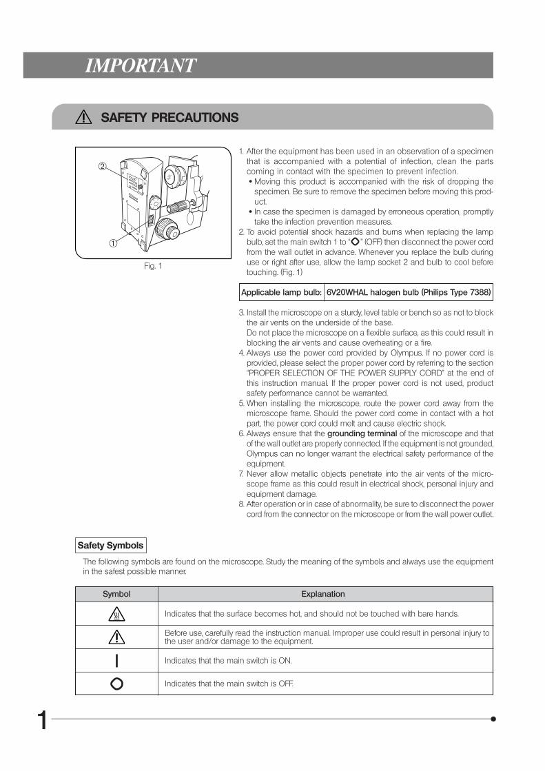
2. To avoid potential shock hazards and burns when replacing the lampbulb, set the main switch 1 to “ ” (OFF) then disconnect the power cordfrom the wall outlet in advance. Whenever you replace the bulb duringuse or right after use, allow the lamp socket 2 and bulb to cool beforetouching. (Fig. 1)
Applicable lamp bulb: 6V20WHAL halogen bulb (Philips Type 7388)
3. Install the microscope on a sturdy, level table or bench so as not to blockthe air vents on the underside of the base.Do not place the microscope on a flexible surface, as this could result inblocking the air vents and cause overheating or a fire.
4. Always use the power cord provided by Olympus. If no power cord isprovided, please select the proper power cord by referring to the section“PROPER SELECTION OF THE POWER SUPPLY CORD” at the end ofthis instruction manual. If the proper power cord is not used, productsafety performance cannot be warranted.
5. When installing the microscope, route the power cord away from themicroscope frame. Should the power cord come in contact with a hotpart, the power cord could melt and cause electric shock.
6. Always ensure that the grounding terminal of the microscope and thatof the wall outlet are properly connected. If the equipment is not grounded,Olympus can no longer warrant the electrical safety performance of theequipment.
7. Never allow metallic objects penetrate into the air vents of the micro-scope frame as this could result in electrical shock, personal injury andequipment damage.
8. After operation or in case of abnormality, be sure to disconnect the powercord from the connector on the microscope or from the wall power outlet.
Fig. 1
Safety Symbols
The following symbols are found on the microscope. Study the meaning of the symbols and always use the equipmentin the safest possible manner.
Symbol Explanation
Indicates that the surface becomes hot, and should not be touched with bare hands.
Indicates that the main switch is ON.
Indicates that the main switch is OFF.
Before use, carefully read the instruction manual. Improper use could result in personal injury tothe user and/or damage to the equipment.
@
²
2
CX21
Warning Label
A warning indication label is attached to every part where special precaution is required when handling and using themicroscope. Always heed the warnings.
Warning labelposition
Bottom of microscopeframe
[Warning against high temperature inlamp bulb replacement]
If the warning label is stained or peeled off, contact Olympus.
1 Getting Ready
1. A microscope is a precision instrument. Handle it with care and avoidsubjecting it to sudden or severe impact.
2. Do not use the microscope where it is subjected to direct sunlight,high temperature and humidity, dust or vibrations. (For the operatingconditions, see chapter 7, “SPECIFICATIONS” on Page 15.)
3. Always use the tension adjustment ring to adjust the rotation tension ofthe coarse adjustment knob.
4. The microscope is ventilated by natural convection. Be sure to leaveenough spaces (10 cm or more) around it when installing it.
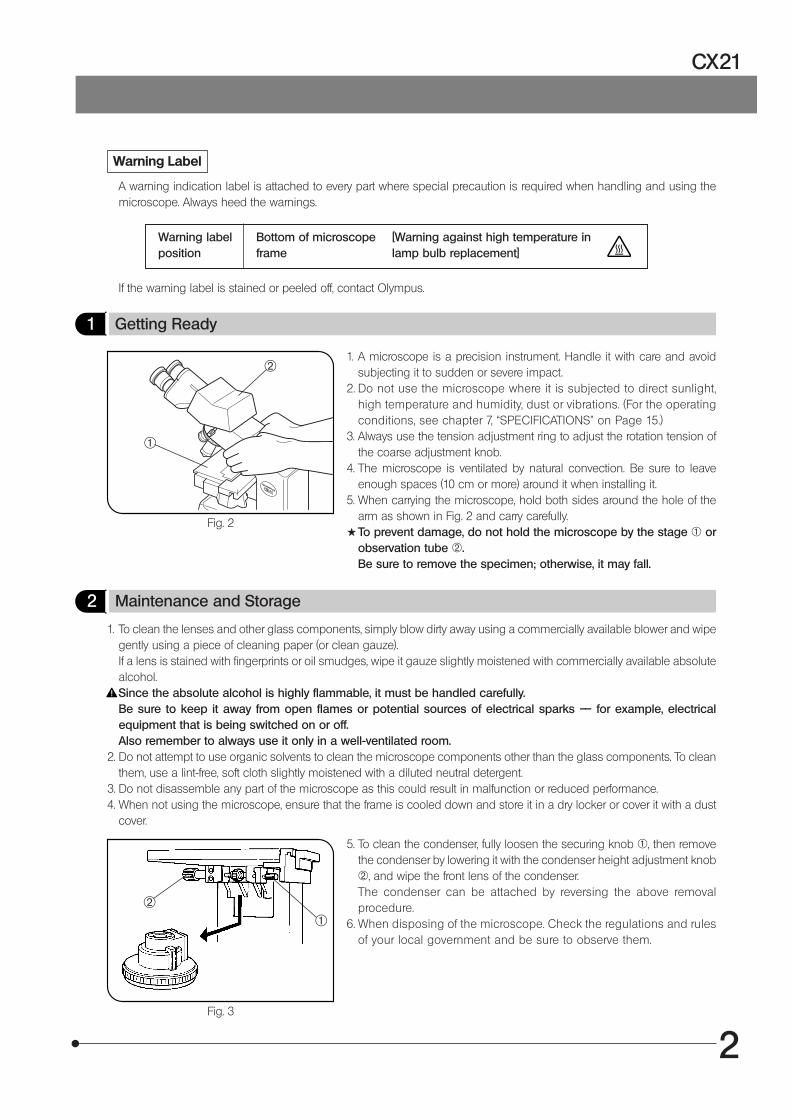
5. When carrying the microscope, hold both sides around the hole of thearm as shown in Fig. 2 and carry carefully.
#To prevent damage, do not hold the microscope by the stage 1 orobservation tube 2.Be sure to remove the specimen; otherwise, it may fall.
Fig. 2
2 Maintenance and Storage
1. To clean the lenses and other glass components, simply blow dirty away using a commercially available blower and wipegently using a piece of cleaning paper (or clean gauze).If a lens is stained with fingerprints or oil smudges, wipe it gauze slightly moistened with commercially available absolutealcohol.Since the absolute alcohol is highly flammable, it must be handled carefully.Be sure to keep it away from open flames or potential sources of electrical sparks –– for example, electricalequipment that is being switched on or off.Also remember to always use it only in a well-ventilated room.
2. Do not attempt to use organic solvents to clean the microscope components other than the glass components. To cleanthem, use a lint-free, soft cloth slightly moistened with a diluted neutral detergent.
3. Do not disassemble any part of the microscope as this could result in malfunction or reduced performance.4. When not using the microscope, ensure that the frame is cooled down and store it in a dry locker or cover it with a dust
cover.
Fig. 3
5. To clean the condenser, fully loosen the securing knob 1, then removethe condenser by lowering it with the condenser height adjustment knob2, and wipe the front lens of the condenser.The condenser can be attached by reversing the above removalprocedure.
6. When disposing of the microscope. Check the regulations and rulesof your local government and be sure to observe them.
@
²
@²
3
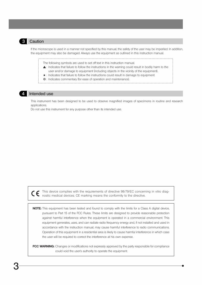
3 Caution
If the microscope is used in a manner not specified by this manual, the safety of the user may be imperiled. In addition,the equipment may also be damaged. Always use the equipment as outlined in this instruction manual.
The following symbols are used to set off text in this instruction manual.: Indicates that failure to follow the instructions in the warning could result in bodily harm to the
user and/or damage to equipment (including objects in the vicinity of the equipment).# : Indicates that failure to follow the instructions could result in damage to equipment.} : Indicates commentary (for ease of operation and maintenance).
NOTE: This equipment has been tested and found to comply with the limits for a Class A digital device,
pursuant to Part 15 of the FCC Rules. These limits are designed to provide reasonable protection
against harmful interference when the equipment is operated in a commercial environment. This
equipment generates, uses, and can radiate radio frequency energy and, if not installed and used in
accordance with the instruction manual, may cause harmful interference to radio communications.
Operation of this equipment in a residential area is likely to cause harmful interference in which case
the user will be required to correct the interference at his own expense.
FCC WARNING: Changes or modifications not expressly approved by the party responsible for compliance
could void the user’s authority to operate the equipment.
This device complies with the requirements of directive 98/79/EC concerning in vitro diag-nostic medical devices. CE marking means the conformity to the directive.
4 Intended use
This instrument has been designed to be used to observe magnified images of specimens in routine and researchapplications.Do not use this instrument for any purpose other than its intended use.
4
CX21
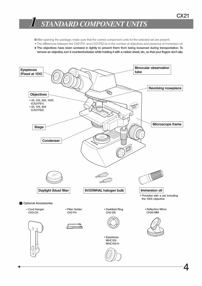
STANDARD COMPONENT UNITS
}After opening the package, make sure that the correct component units for the selected set are present. · The differences between the CX21FS1 and CX21FS2 lie in the number of objectives and presence of immersion oil.#The objectives have been screwed in tightly to prevent them from being loosened during transportation. To
remove an objective, turn it counterclockwise while holding it with a rubber sheet, etc., so that your fingers don’t slip.
Eyepieces(Fixed at 10X)
Stage
Condenser
Binocular observationtube
Revolving nosepiece
Microscope frame
Objectives
· 4X, 10X, 40X, 100X (CX21FS1) · 4X, 10X, 40X (CX21FS2)
6V20WHAL halogen bulb Immersion oil · Provided with a set including
the 100X objective.
Daylight (blue) filter
Optional Accessories
· Cord Hanger CH3-CH
· Filter Holder CH2-FH
· Reflection Mirror CH20-MM
· Eyepieces WHC15X WHC15X-H
· Darkfield Ring CH2-DS
5
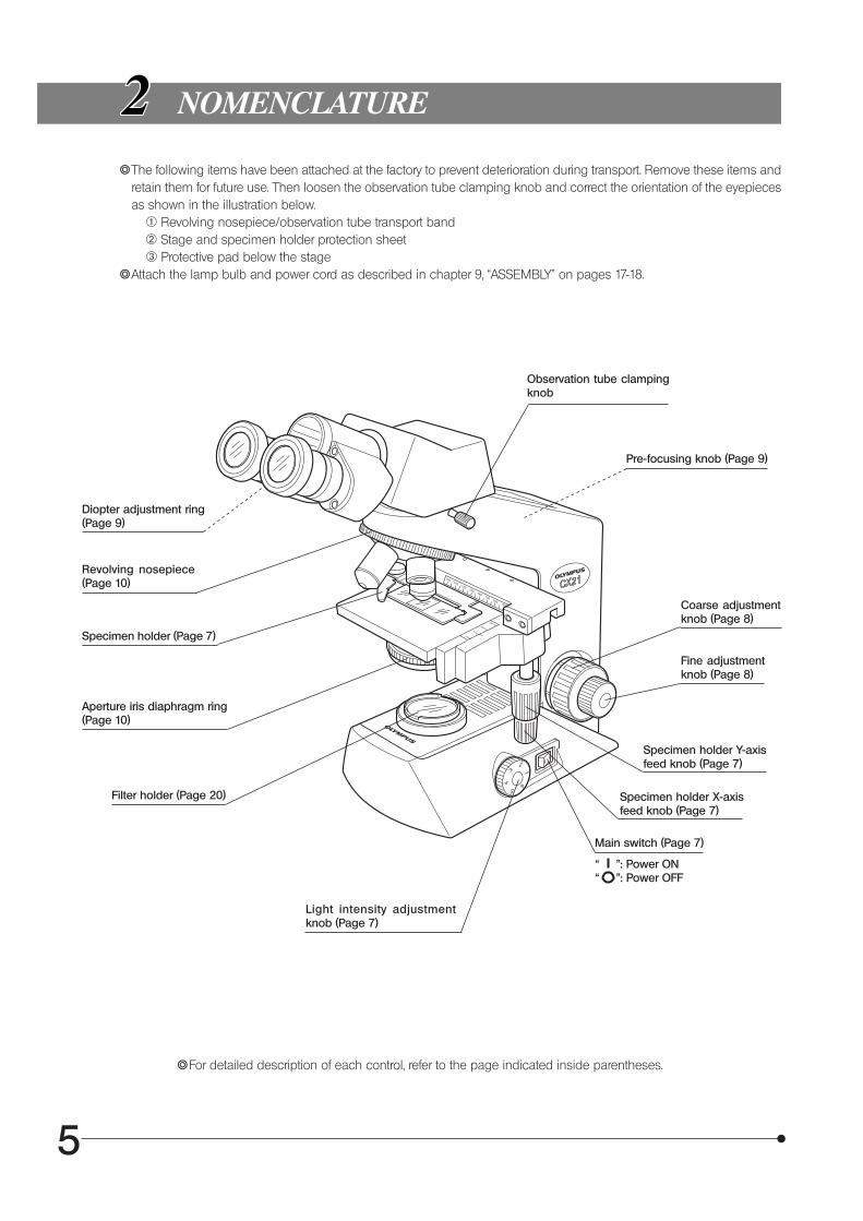
“ ”: Power ON“ ”: Power OFF
NOMENCLATURE
}The following items have been attached at the factory to prevent deterioration during transport. Remove these items andretain them for future use. Then loosen the observation tube clamping knob and correct the orientation of the eyepiecesas shown in the illustration below.
1 Revolving nosepiece/observation tube transport band 2 Stage and specimen holder protection sheet 3 Protective pad below the stage}Attach the lamp bulb and power cord as described in chapter 9, “ASSEMBLY” on pages 17-18.
Diopter adjustment ring(Page 9)
}For detailed description of each control, refer to the page indicated inside parentheses.
Specimen holder (Page 7)
Aperture iris diaphragm ring(Page 10)
Filter holder (Page 20)
Light intensity adjustmentknob (Page 7)
Revolving nosepiece(Page 10)
Observation tube clampingknob
Pre-focusing knob (Page 9)
Specimen holder Y-axisfeed knob (Page 7)
Specimen holder X-axisfeed knob (Page 7)
Fine adjustmentknob (Page 8)
Coarse adjustmentknob (Page 8)
Main switch (Page 7)
6
CX21
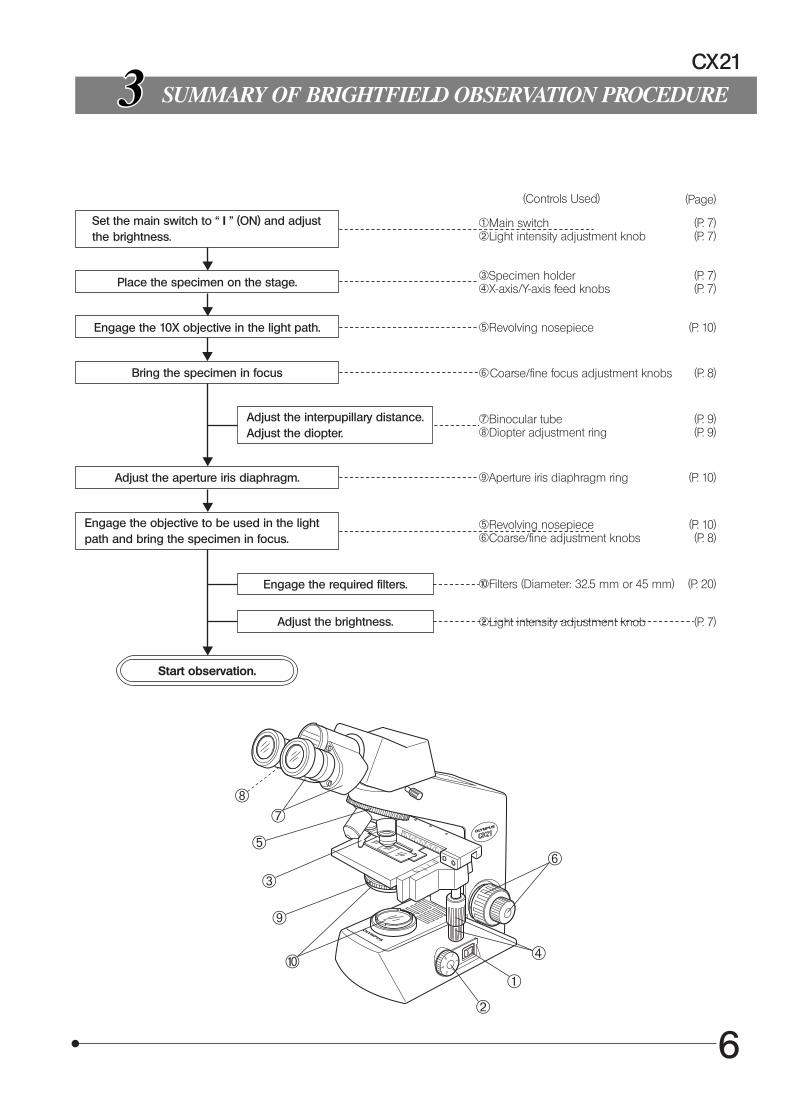
SUMMARY OF BRIGHTFIELD OBSERVATION PROCEDURE
Set the main switch to “ I " (ON) and adjustthe brightness.
1Main switch (P. 7)2Light intensity adjustment knob (P. 7)
Place the specimen on the stage. 3Specimen holder (P. 7)4X-axis/Y-axis feed knobs (P. 7)
Engage the 10X objective in the light path. 5Revolving nosepiece (P. 10)
Bring the specimen in focus 6Coarse/fine focus adjustment knobs (P. 8)
Adjust the interpupillary distance.Adjust the diopter.
7Binocular tube (P. 9)8Diopter adjustment ring (P. 9)
Adjust the aperture iris diaphragm. 9Aperture iris diaphragm ring (P. 10)
Engage the objective to be used in the lightpath and bring the specimen in focus.
aFilters (Diameter: 32.5 mm or 45 mm) (P. 20)Engage the required filters.
5Revolving nosepiece (P. 10)6Coarse/fine adjustment knobs (P. 8)
Adjust the brightness. 2Light intensity adjustment knob (P. 7)
Start observation.
(Controls Used) (Page)
1
2
4
6
a
9
3
5
78
7
Fig. 4
DETAILED OBSERVATION PROCEDURE
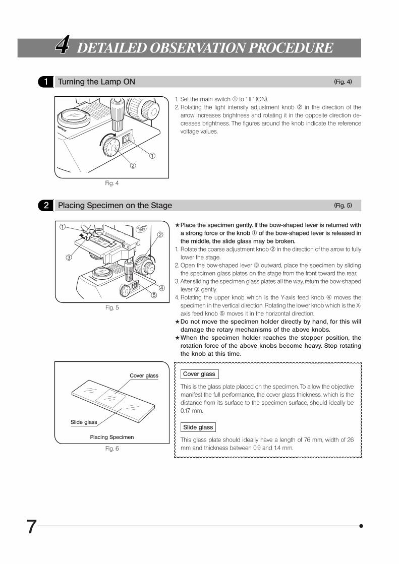
1 Turning the Lamp ON (Fig. 4)
1. Set the main switch 1 to “ I ” (ON).2. Rotating the light intensity adjustment knob 2 in the direction of the
arrow increases brightness and rotating it in the opposite direction de-creases brightness. The figures around the knob indicate the referencevoltage values.
2 Placing Specimen on the Stage (Fig. 5)
Fig. 5
#Place the specimen gently. If the bow-shaped lever is returned witha strong force or the knob 1 of the bow-shaped lever is released inthe middle, the slide glass may be broken.
1. Rotate the coarse adjustment knob 2 in the direction of the arrow to fullylower the stage.
2. Open the bow-shaped lever 3 outward, place the specimen by slidingthe specimen glass plates on the stage from the front toward the rear.
3. After sliding the specimen glass plates all the way, return the bow-shapedlever 3 gently.
4. Rotating the upper knob which is the Y-axis feed knob 4 moves thespecimen in the vertical direction. Rotating the lower knob which is the X-axis feed knob 5 moves it in the horizontal direction.
#Do not move the specimen holder directly by hand, for this willdamage the rotary mechanisms of the above knobs.
#When the specimen holder reaches the stopper position, therotation force of the above knobs become heavy. Stop rotatingthe knob at this time.
Cover glass
This is the glass plate placed on the specimen. To allow the objectivemanifest the full performance, the cover glass thickness, which is thedistance from its surface to the specimen surface, should ideally be0.17 mm.
Slide glass
This glass plate should ideally have a length of 76 mm, width of 26mm and thickness between 0.9 and 1.4 mm.Fig. 6
Placing Specimen
²@
²@
|
³
5
Cover glass
Slide glass
8
CX21
Fig. 7
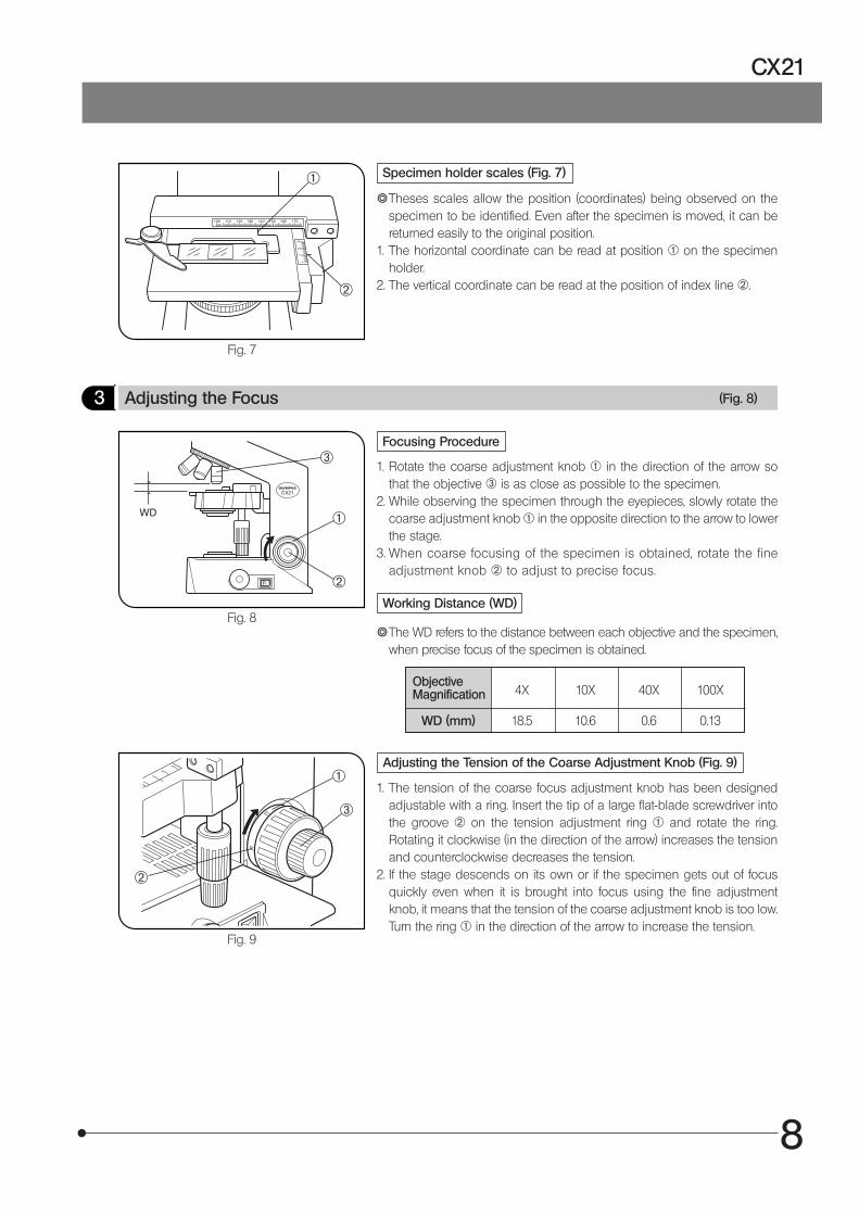
Specimen holder scales (Fig. 7)
}Theses scales allow the position (coordinates) being observed on thespecimen to be identified. Even after the specimen is moved, it can bereturned easily to the original position.
1. The horizontal coordinate can be read at position 1 on the specimenholder.
2. The vertical coordinate can be read at the position of index line 2.
Fig. 8
3 Adjusting the Focus (Fig. 8)
Focusing Procedure
1. Rotate the coarse adjustment knob @ in the direction of the arrow sothat the objective 3 is as close as possible to the specimen.
2. While observing the specimen through the eyepieces, slowly rotate thecoarse adjustment knob 1 in the opposite direction to the arrow to lowerthe stage.
3. When coarse focusing of the specimen is obtained, rotate the fineadjustment knob 2 to adjust to precise focus.
Working Distance (WD)
}The WD refers to the distance between each objective and the specimen,when precise focus of the specimen is obtained.
ObjectiveMagnification 4X 10X 40X 100X
WD (mm) 18.5 10.6 0.6 0.13
Fig. 9
Adjusting the Tension of the Coarse Adjustment Knob (Fig. 9)
1. The tension of the coarse focus adjustment knob has been designedadjustable with a ring. Insert the tip of a large flat-blade screwdriver intothe groove 2 on the tension adjustment ring 1 and rotate the ring.Rotating it clockwise (in the direction of the arrow) increases the tensionand counterclockwise decreases the tension.
2. If the stage descends on its own or if the specimen gets out of focusquickly even when it is brought into focus using the fine adjustmentknob, it means that the tension of the coarse adjustment knob is too low.Turn the ring 1 in the direction of the arrow to increase the tension.
²
@
²
@
³
²
@
³
9
Fig. 10
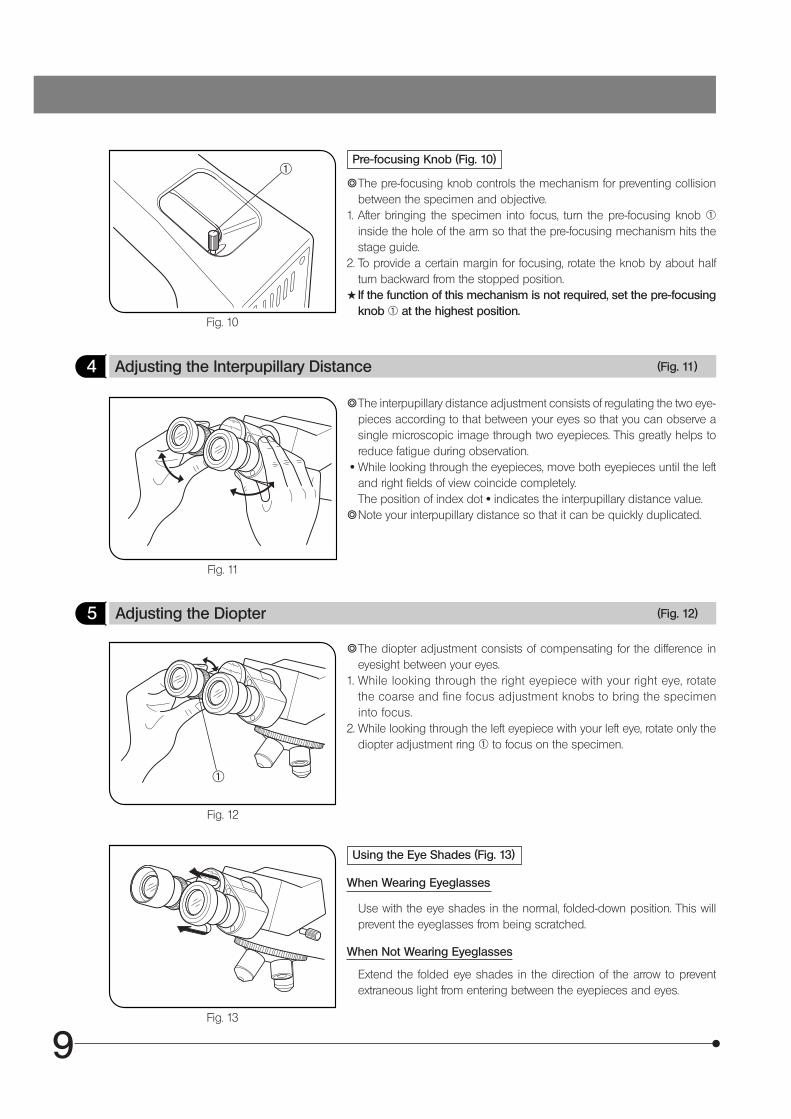
Pre-focusing Knob (Fig. 10)
}The pre-focusing knob controls the mechanism for preventing collisionbetween the specimen and objective.
1. After bringing the specimen into focus, turn the pre-focusing knob 1inside the hole of the arm so that the pre-focusing mechanism hits thestage guide.
2. To provide a certain margin for focusing, rotate the knob by about halfturn backward from the stopped position.
#If the function of this mechanism is not required, set the pre-focusingknob 1 at the highest position.
4 Adjusting the Interpupillary Distance (Fig. 11)
Fig. 11
}The interpupillary distance adjustment consists of regulating the two eye-pieces according to that between your eyes so that you can observe asingle microscopic image through two eyepieces. This greatly helps toreduce fatigue during observation.
· While looking through the eyepieces, move both eyepieces until the leftand right fields of view coincide completely.The position of index dot · indicates the interpupillary distance value.
}Note your interpupillary distance so that it can be quickly duplicated.
Fig. 12
Fig. 13
5 Adjusting the Diopter (Fig. 12)
}The diopter adjustment consists of compensating for the difference ineyesight between your eyes.
1. While looking through the right eyepiece with your right eye, rotatethe coarse and fine focus adjustment knobs to bring the specimeninto focus.
2. While looking through the left eyepiece with your left eye, rotate only thediopter adjustment ring 1 to focus on the specimen.
Using the Eye Shades (Fig. 13)
When Wearing Eyeglasses
Use with the eye shades in the normal, folded-down position. This willprevent the eyeglasses from being scratched.
When Not Wearing Eyeglasses
Extend the folded eye shades in the direction of the arrow to preventextraneous light from entering between the eyepieces and eyes.
@
@
10
CX21
Fig. 14
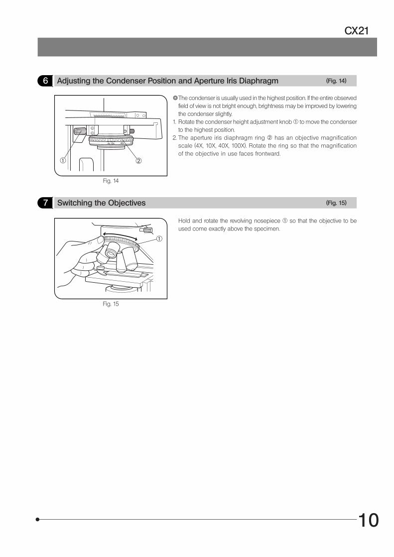
6 Adjusting the Condenser Position and Aperture Iris Diaphragm (Fig. 14)
}The condenser is usually used in the highest position. If the entire observedfield of view is not bright enough, brightness may be improved by loweringthe condenser slightly.
1. Rotate the condenser height adjustment knob 1 to move the condenserto the highest position.
2. The aperture iris diaphragm ring 2 has an objective magnificationscale (4X, 10X, 40X, 100X). Rotate the ring so that the magnificationof the objective in use faces frontward.
7 Switching the Objectives (Fig. 15)
Fig. 15
Hold and rotate the revolving nosepiece 1 so that the objective to beused come exactly above the specimen.
²@
@
11
Fig. 16
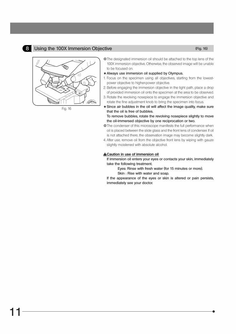
8 Using the 100X Immersion Objective (Fig. 16)
}The designated immersion oil should be attached to the top lens of the100X immersion objective. Otherwise, the observed image will be unableto be focused on.
#Always use immersion oil supplied by Olympus.1. Focus on the specimen using all objectives, starting from the lowest-
power objective to higher-power objective.2. Before engaging the immersion objective in the light path, place a drop
of provided immersion oil onto the specimen at the area to be observed.3. Rotate the revolving nosepiece to engage the immersion objective and
rotate the fine adjustment knob to bring the specimen into focus.#Since air bubbles in the oil will affect the image quality, make sure
that the oil is free of bubbles.To remove bubbles, rotate the revolving nosepiece slightly to movethe oil-immersed objective by one reciprocation or two.
}The condenser of this microscope manifests the full performance whenoil is placed between the slide glass and the front lens of condenser. If oilis not attached there, the observation image may become slightly dark.
4. After use, remove oil from the objective front lens by wiping with gauzeslightly moistened with absolute alcohol.
Caution in use of immersion oilIf immersion oil enters your eyes or contacts your skin, immediatelytake the following treatment.
Eyes: Rinse with fresh water (for 15 minutes or more).Skin : Rise with water and soap.
If the appearance of the eyes or skin is altered or pain persists,immediately see your doctor.
12
CX21
ONE-POINT ADVICE
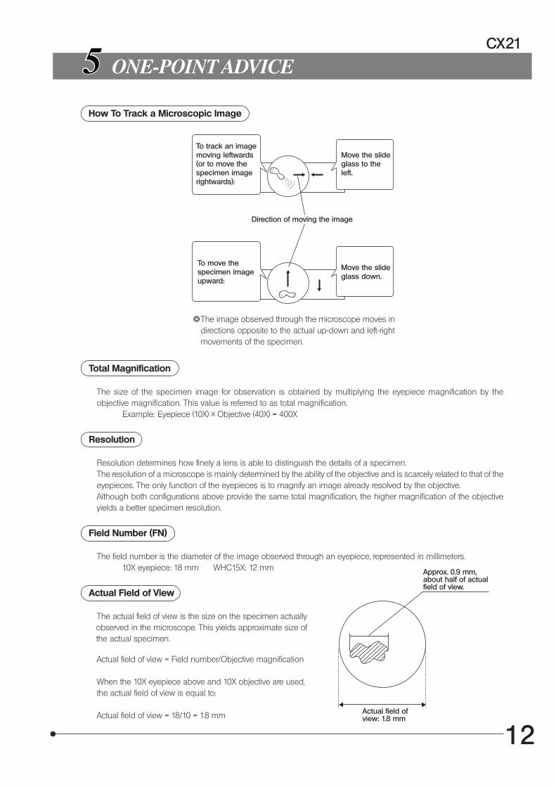
How To Track a Microscopic Image
To track an imagemoving leftwards(or to move thespecimen imagerightwards):
Direction of moving the image
Total Magnification
The size of the specimen image for observation is obtained by multiplying the eyepiece magnification by theobjective magnification. This value is referred to as total magnification.
Example: Eyepiece (10X) x Objective (40X) = 400X
Resolution
Resolution determines how finely a lens is able to distinguish the details of a specimen.The resolution of a microscope is mainly determined by the ability of the objective and is scarcely related to that of theeyepieces. The only function of the eyepieces is to magnify an image already resolved by the objective.Although both configurations above provide the same total magnification, the higher magnification of the objectiveyields a better specimen resolution.
Field Number (FN)
The field number is the diameter of the image observed through an eyepiece, represented in millimeters.10X eyepiece: 18 mm WHC15X: 12 mm
Actual Field of View
The actual field of view is the size on the specimen actually observed in the microscope. This yields approximate size of the actual specimen.
Actual field of view = Field number/Objective magnification
When the 10X eyepiece above and 10X objective are used,the actual field of view is equal to:
Actual field of view = 18/10 = 1.8 mm
Move the slideglass to theleft.
To move thespecimen imageupward:
Move the slideglass down.
}The image observed through the microscope moves indirections opposite to the actual up-down and left-rightmovements of the specimen.
Actual field ofview: 1.8 mm
Approx. 0.9 mm,about half of actualfield of view.
13
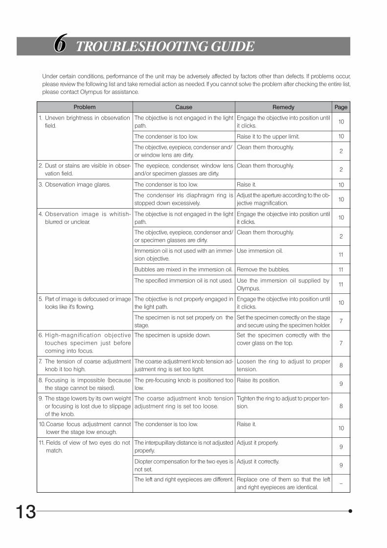
TROUBLESHOOTING GUIDE
Under certain conditions, performance of the unit may be adversely affected by factors other than defects. If problems occur,please review the following list and take remedial action as needed. If you cannot solve the problem after checking the entire list,please contact Olympus for assistance.
Problem Cause Remedy Page
101. Uneven brightness in observation
field.The objective is not engaged in the lightpath.
Engage the objective into position untilit clicks.
The condenser is too low. Raise it to the upper limit.
The objective, eyepiece, condenser and/or window lens are dirty.
Clean them thoroughly.
10
2
2. Dust or stains are visible in obser-vation field.
The eyepiece, condenser, window lensand/or specimen glasses are dirty.
Clean them thoroughly.2
3. Observation image glares. The condenser is too low. Raise it.
The condenser iris diaphragm ring isstopped down excessively.
Adjust the aperture according to the ob-jective magnification.
10
10
4. Observation image is whitish-blurred or unclear.
The objective is not engaged in the lightpath.
Engage the objective into position untilit clicks.
The objective, eyepiece, condenser and/or specimen glasses are dirty.
Clean them thoroughly.
10
2
Immersion oil is not used with an immer-sion objective.
Use immersion oil.
Bubbles are mixed in the immersion oil. Remove the bubbles.
The specified immersion oil is not used. Use the immersion oil supplied byOlympus.
11
11
11
5. Part of image is defocused or imagelooks like it’s flowing.
The objective is not properly engaged inthe light path.
Engage the objective into position untilit clicks.
The specimen is not set properly on thestage.
Set the specimen correctly on the stageand secure using the specimen holder.
6. High-magni f icat ion object ivetouches specimen just beforecoming into focus.
The specimen is upside down. Set the specimen correctly with thecover glass on the top.
7. The tension of coarse adjustmentknob it too high.
The coarse adjustment knob tension ad-justment ring is set too tight.
Loosen the ring to adjust to propertension.
10
7
7
8
8. Focusing is impossible (becausethe stage cannot be raised).
The pre-focusing knob is positioned toolow.
Raise its position.9
9. The stage lowers by its own weightor focusing is lost due to slippageof the knob.
The coarse adjustment knob tensionadjustment ring is set too loose.
Tighten the ring to adjust to proper ten-sion.
10.Coarse focus adjustment cannotlower the stage low enough.
The condenser is too low. Raise it.
8
10
11. Fields of view of two eyes do notmatch.
The interpupillary distance is not adjustedproperly.
Adjust it properly.9
Diopter compensation for the two eyes isnot set.
Adjust it correctly.
The left and right eyepieces are different. Replace one of them so that the leftand right eyepieces are identical.
9
--

14
CX21
Problem Cause Remedy Page
7
7
17
17
18
17
12. Objective hits the specimen whenan objective is switched to a higher-magnification objective.
The specimen is upside down. Set the specimen correctly with thecover glass on the top.
The cover glass is too thick. Use a cover glass with thickness of0.17 mm.
13. Lamp bulb does not light. Lamp bulb is not mounted. Attach a bulb.
Lamp bulb is blown. Replace the bulb.
The power cord is unplugged. Plug it securely.
14. Lamp bulb blows easily. The specified bulb is not used. Replace with a specified bulb.
15
SPECIFICATIONS
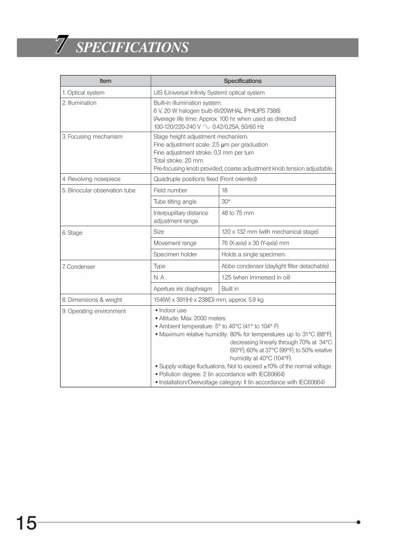
Item Specifications
1. Optical system UIS (Universal Infinity System) optical system
2. Illumination Built-in illumination system.6 V, 20 W halogen bulb 6V20WHAL (PHILIPS 7388)(Average life time: Approx. 100 hr. when used as directed)100-120/220-240 V 0.42/0.25A, 50/60 Hz
3. Focusing mechanism Stage height adjustment mechanism.Fine adjustment scale: 2.5 μm per graduationFine adjustment stroke: 0.3 mm per turnTotal stroke: 20 mm.Pre-focusing knob provided, coarse adjustment knob tension adjustable.
4. Revolving nosepiece Quadruple positions fixed (Front oriented)
5. Binocular observation tube Field number 18
Tube tilting angle 30°
Interpupillary distanceadjustment range
48 to 75 mm
6. Stage Size 120 x 132 mm (with mechanical stage)
Movement range 76 (X-axis) x 30 (Y-axis) mm
Specimen holder Holds a single specimen.
7. Condenser Type Abbe condenser (daylight filter detachable)
N. A . 1.25 (when immersed in oil)
Aperture iris diaphragm Built in
8. Dimensions & weight 154(W) x 391(H) x 238(D) mm, approx. 5.9 kg
9. Operating environment · Indoor use. · Altitude: Max. 2000 meters · Ambient temperature: 5° to 40°C (41° to 104° F) · Maximum relative humidity: 80% for temperatures up to 31°C (88°F),
decreasing linearly through 70% at 34°C(93°F), 60% at 37°C (99°F), to 50% relativehumidity at 40°C (104°F).
· Supply voltage fluctuations; Not to exceed ±10% of the normal voltage. · Pollution degree: 2 (in accordance with IEC60664) · Installation/Overvoltage category: II (in accordance with IEC60664)
16
CX21
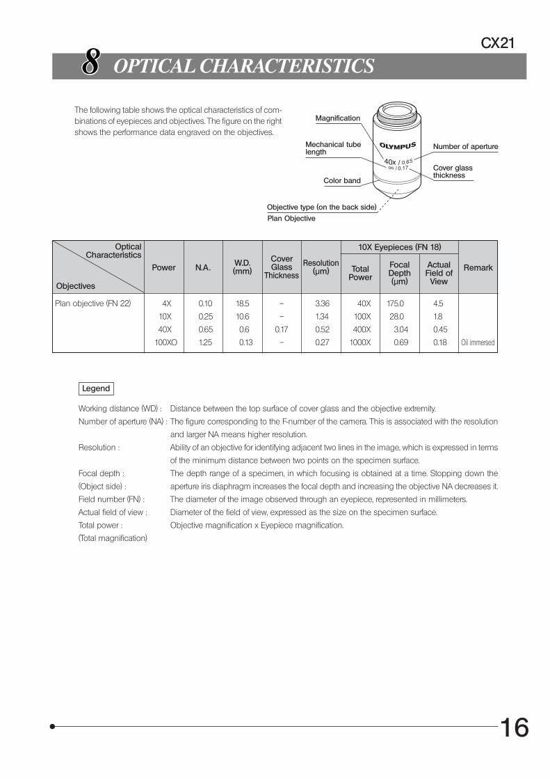
OPTICAL CHARACTERISTICS
OpticalCharacteristics
Objectives
Power N.A . W.D.(mm)
CoverGlass
Thickness
Resolution(μm)
10X Eyepieces (FN 18)
TotalPower
FocalDepth(μm)
ActualField of
View
Remark
Plan objective (FN 22) 4X 0.10 18.5 – 3.36 40X 175.0 4.5
10X 0.25 10.6 – 1.34 100X 28.0 1.8
40X 0.65 0.6 0.17 0.52 400X 3.04 0.45
100XO 1.25 0.13 – 0.27 1000X 0.69 0.18 Oil immersed
Legend
Working distance (WD) : Distance between the top surface of cover glass and the objective extremity.
Number of aperture (NA) : The figure corresponding to the F-number of the camera. This is associated with the resolution
and larger NA means higher resolution.
Resolution : Ability of an objective for identifying adjacent two lines in the image, which is expressed in terms
of the minimum distance between two points on the specimen surface.
Focal depth : The depth range of a specimen, in which focusing is obtained at a time. Stopping down the
aperture iris diaphragm increases the focal depth and increasing the objective NA decreases it.
Field number (FN) : The diameter of the image observed through an eyepiece, represented in millimeters.
Actual field of view : Diameter of the field of view, expressed as the size on the specimen surface.
Total power : Objective magnification x Eyepiece magnification.
(Total magnification)
(Object side) :
The following table shows the optical characteristics of com-binations of eyepieces and objectives. The figure on the rightshows the performance data engraved on the objectives.
Magnification
Mechanical tubelength
Color band
Objective type (on the back side)
Number of aperture
Cover glassthickness
Plan Objective
17
ASSEMBLY
}Each standard set can be assembled by simply attaching the lamp bulb, daylight (blue) filter and power cord.
Fig. 17
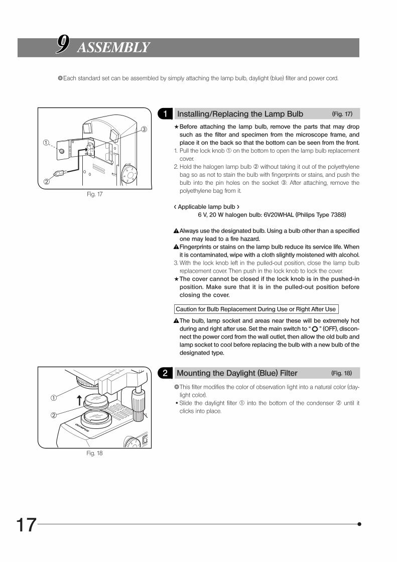
1 Installing/Replacing the Lamp Bulb (Fig. 17)
#Before attaching the lamp bulb, remove the parts that may dropsuch as the filter and specimen from the microscope frame, andplace it on the back so that the bottom can be seen from the front.
1. Pull the lock knob 1 on the bottom to open the lamp bulb replacementcover.
2. Hold the halogen lamp bulb 2 without taking it out of the polyethylenebag so as not to stain the bulb with fingerprints or stains, and push thebulb into the pin holes on the socket 3. After attaching, remove thepolyethylene bag from it.
< Applicable lamp bulb >6 V, 20 W halogen bulb: 6V20WHAL (Philips Type 7388)
Always use the designated bulb. Using a bulb other than a specifiedone may lead to a fire hazard.Fingerprints or stains on the lamp bulb reduce its service life. Whenit is contaminated, wipe with a cloth slightly moistened with alcohol.
3. With the lock knob left in the pulled-out position, close the lamp bulbreplacement cover. Then push in the lock knob to lock the cover.
#The cover cannot be closed if the lock knob is in the pushed-inposition. Make sure that it is in the pulled-out position beforeclosing the cover.
Caution for Bulb Replacement During Use or Right After Use
The bulb, lamp socket and areas near these will be extremely hotduring and right after use. Set the main switch to “ ” (OFF), discon-nect the power cord from the wall outlet, then allow the old bulb andlamp socket to cool before replacing the bulb with a new bulb of thedesignated type.
Fig. 18
2 Mounting the Daylight (Blue) Filter (Fig. 18)
}This filter modifies the color of observation light into a natural color (day-light color).
· Slide the daylight filter 1 into the bottom of the condenser 2 until itclicks into place.
²
@
³
²
@
18
CX21
Fig. 19
Fig. 20
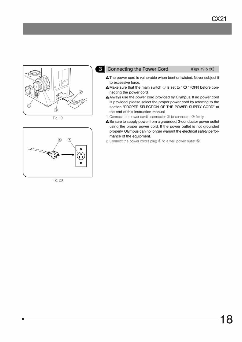
3 Connecting the Power Cord (Figs. 19 & 20)
The power cord is vulnerable when bent or twisted. Never subject itto excessive force.Make sure that the main switch 1 is set to “ ” (OFF) before con-necting the power cord.Always use the power cord provided by Olympus. If no power cordis provided, please select the proper power cord by referring to thesection “PROPER SELECTION OF THE POWER SUPPLY CORD” atthe end of this instruction manual.
1. Connect the power cord’s connector 2 to connector 3 firmly.Be sure to supply power from a grounded, 3-conductor power outletusing the proper power cord. If the power outlet is not groundedproperly, Olympus can no longer warrant the electrical safety perfor-mance of the equipment.
2. Connect the power cord’s plug | to a wall power outlet 5.
²
@³
5|
19
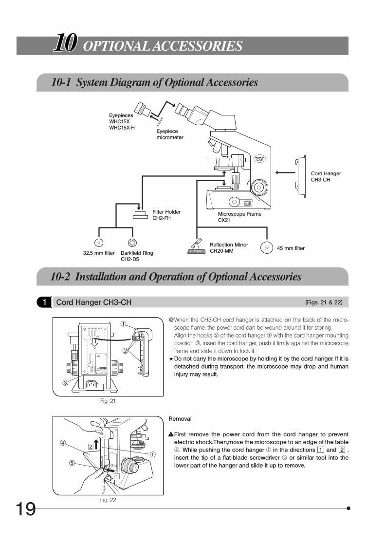
OPTIONAL ACCESSORIES
10-1 System Diagram of Optional Accessories
Fig. 21
Fig. 22
10-2 Installation and Operation of Optional Accessories
1 Cord Hanger CH3-CH (Figs. 21 & 22)
}When the CH3-CH cord hanger is attached on the back of the micro-scope frame, the power cord can be wound around it for storing.Align the hooks 2 of the cord hanger 1 with the cord hanger mountingposition 3, insert the cord hanger, push it firmly against the microscopeframe and slide it down to lock it.
#Do not carry the microscope by holding it by the cord hanger. If it isdetached during transport, the microscope may drop and humaninjury may result.
Removal
First remove the power cord from the cord hanger to preventelectric shock.Then,move the microscope to an edge of the table|. While pushing the cord hanger @ in the directions 1 and 2 ,insert the tip of a flat-blade screwdriver 5 or similar tool into thelower part of the hanger and slide it up to remove.
EyepiecesWHC15XWHC15X-H
Filter HolderCH2-FH
Reflection MirrorCH20-MM 45 mm filter
32.5 mm filter Darkfield RingCH2-DS
Cord HangerCH3-CH
Microscope FrameCX21
|
@5
²
@
³
Eyepiecemicrometer
20
CX21
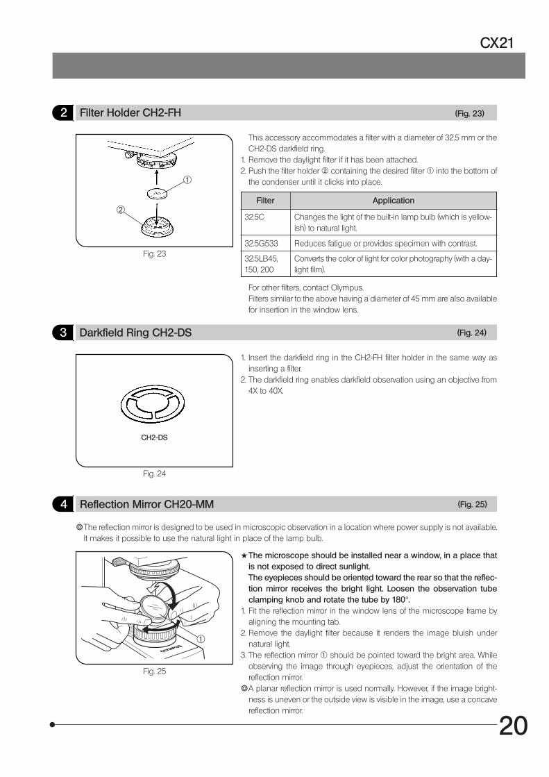
4 Reflection Mirror CH20-MM (Fig. 25)
}The reflection mirror is designed to be used in microscopic observation in a location where power supply is not available.It makes it possible to use the natural light in place of the lamp bulb.
Fig. 25
#The microscope should be installed near a window, in a place thatis not exposed to direct sunlight.The eyepieces should be oriented toward the rear so that the reflec-tion mirror receives the bright light. Loosen the observation tubeclamping knob and rotate the tube by 180°.
1. Fit the reflection mirror in the window lens of the microscope frame byaligning the mounting tab.
2. Remove the daylight filter because it renders the image bluish undernatural light.
3. The reflection mirror 1 should be pointed toward the bright area. Whileobserving the image through eyepieces, adjust the orientation of thereflection mirror.
}A planar reflection mirror is used normally. However, if the image bright-ness is uneven or the outside view is visible in the image, use a concavereflection mirror.
@
Fig. 23
2 Filter Holder CH2-FH (Fig. 23)
This accessory accommodates a filter with a diameter of 32.5 mm or theCH2-DS darkfield ring.
1. Remove the daylight filter if it has been attached.2. Push the filter holder 2 containing the desired filter 1 into the bottom of
the condenser until it clicks into place.
Filter Application
32.5C Changes the light of the built-in lamp bulb (which is yellow-ish) to natural light.
32.5G533 Reduces fatigue or provides specimen with contrast.
32.5LB45,150, 200
Converts the color of light for color photography (with a day-light film).
For other filters, contact Olympus.Filters similar to the above having a diameter of 45 mm are also availablefor insertion in the window lens.
Fig. 24
3 Darkfield Ring CH2-DS (Fig. 24)
1. Insert the darkfield ring in the CH2-FH filter holder in the same way asinserting a filter.
2. The darkfield ring enables darkfield observation using an objective from4X to 40X.
CH2-DS
²
@
21
Fig. 26
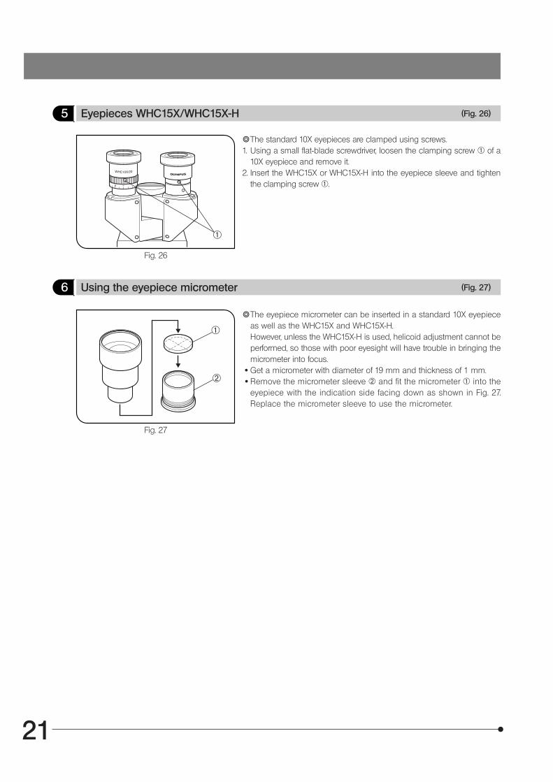
5 Eyepieces WHC15X/WHC15X-H (Fig. 26)
}The standard 10X eyepieces are clamped using screws.1. Using a small flat-blade screwdriver, loosen the clamping screw 1 of a
10X eyepiece and remove it.2. Insert the WHC15X or WHC15X-H into the eyepiece sleeve and tighten
the clamping screw 1.
@
}The eyepiece micrometer can be inserted in a standard 10X eyepieceas well as the WHC15X and WHC15X-H.However, unless the WHC15X-H is used, helicoid adjustment cannot beperformed, so those with poor eyesight will have trouble in bringing themicrometer into focus.
· Get a micrometer with diameter of 19 mm and thickness of 1 mm. · Remove the micrometer sleeve ² and fit the micrometer @ into the
eyepiece with the indication side facing down as shown in Fig. 27.Replace the micrometer sleeve to use the micrometer.
6 Using the eyepiece micrometer (Fig. 27)
Fig. 27
@
²
22
CX21
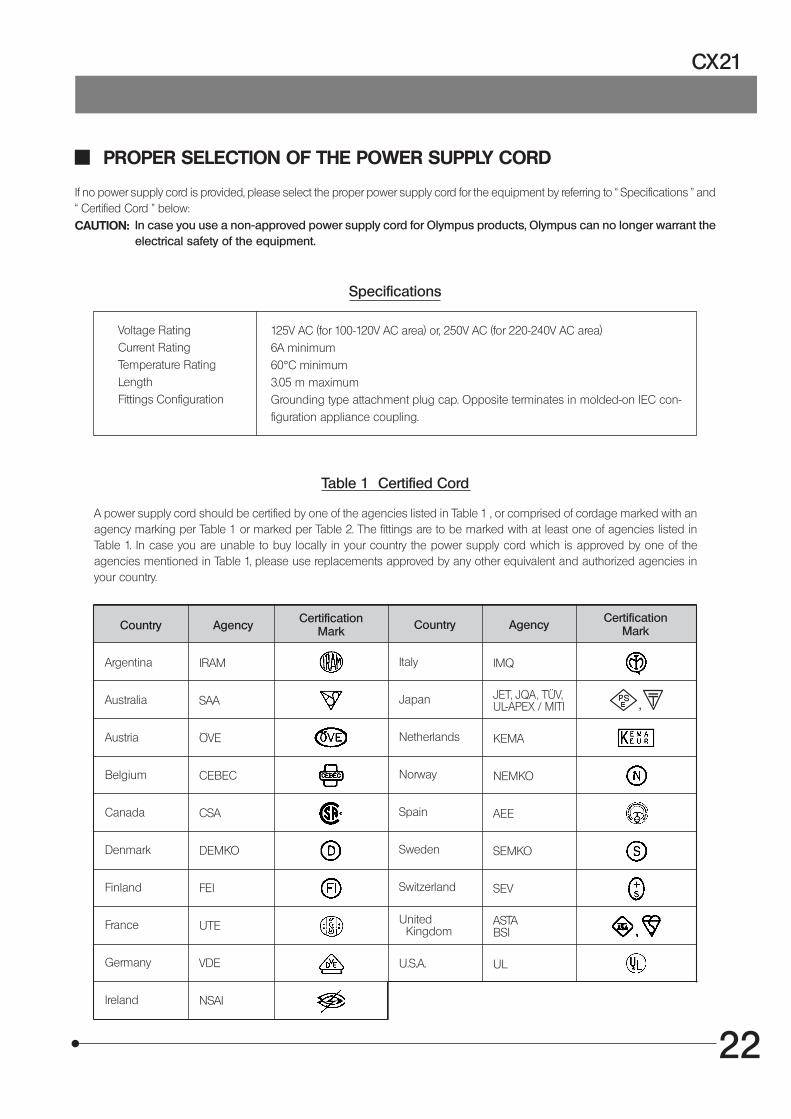
PROPER SELECTION OF THE POWER SUPPLY CORD
If no power supply cord is provided, please select the proper power supply cord for the equipment by referring to “ Specifications ” and“ Certified Cord ” below:CAUTION: In case you use a non-approved power supply cord for Olympus products, Olympus can no longer warrant the
electrical safety of the equipment.
Specifications
Voltage RatingCurrent RatingTemperature RatingLengthFittings Configuration
125V AC (for 100-120V AC area) or, 250V AC (for 220-240V AC area)6A minimum60°C minimum3.05 m maximumGrounding type attachment plug cap. Opposite terminates in molded-on IEC con-figuration appliance coupling.
Table 1 Certified Cord
A power supply cord should be certified by one of the agencies listed in Table 1 , or comprised of cordage marked with anagency marking per Table 1 or marked per Table 2. The fittings are to be marked with at least one of agencies listed inTable 1. In case you are unable to buy locally in your country the power supply cord which is approved by one of theagencies mentioned in Table 1, please use replacements approved by any other equivalent and authorized agencies inyour country.
Country AgencyCertification
Mark Country AgencyCertification
Mark
Argentina
Australia
Austria
Belgium
Canada
Denmark
Finland
France
Germany
Ireland
IRAM
SAA
ÖVE
CEBEC
CSA
DEMKO
FEI
UTE
VDE
NSAI
Italy
Japan
Netherlands
Norway
Spain
Sweden
Switzerland
United Kingdom
U.S.A.
IMQ
ASTABSI
UL
KEMA
NEMKO
AEE
SEMKO
SEV
JET, JQA, TÜV,UL-APEX / MITI

23
Table 2 HAR Flexible Cord
APPROVAL ORGANIZATIONS AND CORDAGE HARMONIZATION MARKING METHODS
Approval Organization
Printed or Embossed Harmoniza-tion Marking (May be located onjacket or insulation of internal wir-ing)
Alternative Marking UtilizingBlack-Red-Yellow Thread (Lengthof color section in mm)
Black Red Yellow
Comite Electrotechnique Belge(CEBEC)
Verband Deutscher Elektrotechniker(VDE) e.V. Prüfstelle
Union Technique de l´Electricite´(UTE)
Instituto Italiano del Marchio diQualita´ (IMQ)
British Approvals Service for ElectricCables (BASEC)
N.V. KEMA
SEMKO AB Svenska ElektriskaMaterielkontrollanstalter
Österreichischer Verband fürElektrotechnik (ÖVE)
Danmarks Elektriske Materialkontroll(DEMKO)
National Standards Authority of Ireland(NSAI)
Norges Elektriske Materiellkontroll(NEMKO)
Asociacion Electrotecnica YElectronica Espanola (AEE)
Hellenic Organization forStandardization (ELOT)
Instituto Portages da Qualidade(IPQ)
Schweizerischer ElektroTechnischer Verein (SEV)
Elektriska Inspektoratet
CEBEC <HAR>
<VDE> <HAR>
USE <HAR>
IEMMEQU <HAR>
BASEC <HAR>
KEMA-KEUR <HAR>
SEMKO <HAR>
<ÖVE> <HAR>
<DEMKO> <HAR>
<NSAI> <HAR>
NEMKO <HAR>
<UNED> <HAR>
ELOT <HAR>
np <HAR>
SEV <HAR>
SETI <HAR>
10 30 10
30 10 10
30 10 30
10 30 50
10 10 30
10 30 30
10 10 50
30 10 50
30 10 30
30 30 50
10 10 70
30 10 70
30 30 70
10 10 90
10 30 90
10 30 90
Underwriters Laboratories Inc. (UL) SV, SVT, SJ or SJT, 3 X 18AWGCanadian Standards Association (CSA) SV, SVT, SJ or SJT, 3 X 18AWG


Shinjuku Monolith, 3-1, Nishi Shinjuku 2-chome, Shinjuku-ku, Tokyo, Japan
Postfach 10 49 08, 20034, Hamburg, Germany
3500 Corporate Parkway, P.O. Box 610, Center Valley, PA 18034-0610, U.S.A.
491B River Valley Road, #12-01/04 Valley Point Office Tower, Singapore 248373
31 Gilby Road, Mount Waverley, VIC., 3149, Australia
5301 Blue Lagoon Drive, Suite 290 Miami, FL 33126, U.S.A.
Printed in Japan on May 21, 2008 M 100–²