Embed Size (px)
Citation preview

W 100Instructions for use
2
Safety instructions
Never open electronic units! If units are opened by customers in breach of thisinstruction, the warranty becomes null and void.
Keep the units away from central heating radiators and electric heaters.Never expose them to direct sunlight.
Use the units in dry rooms only.
Use a damp cloth for cleaning the units. Do not use any cleansing agents orsolvents.
Thank you for choosing Sennheiser!
We have designed this product to give you reliable operation over manyyears. Over half a century of accumulated expertise in the design andmanufacture of high-quality electro-acoustic equipment have made Senn-heiser a world-leading company in this field.
Please take a few moments to read these instructions carefully, as we wantyou to enjoy your new Sennheiser products quickly and to the fullest.
3
Contents
Safety instructions ................................................................................................. 2Contents ................................................................................................................... 3The evolution wireless series ew 100 G2 ........................................................... 4
The channel bank system ............................................................................................. 4System variants ...................................................................................................... 5Overview of operating controls ........................................................................... 6
EM 100 G2 rack-mount receiver .................................................................................. 6EK 100 G2 bodypack receiver ....................................................................................... 7SK 100 G2 bodypack transmitter ................................................................................ 8SKP 100 G2 plug-on transmitter ................................................................................. 9SKM 100 G2 radiomicrophone .................................................................................... 10Indications and displays on the receivers .................................................................. 11Indications and displays on the transmitters ........................................................... 13
Preparing the components for use ..................................................................... 14EM 100 G2 rack-mount receiver .................................................................................. 14EK 100 G2 bodypack receiver ....................................................................................... 17SK 100 G2 bodypack transmitter ................................................................................ 18SKP 100 G2 plug-on transmitter ................................................................................. 19SKM 100 G2 radiomicrophone ..................................................................................... 20
Using the components .......................................................................................... 22Switching the components on/off .............................................................................. 22Muting the transmitters ............................................................................................... 23Activating/deactivating the lock mode ..................................................................... 23Attaching the components to clothing ...................................................................... 24
The operating menu ............................................................................................... 25The buttons ..................................................................................................................... 25Overview of menus ......................................................................................................... 25Working with the operating menu ............................................................................. 26Operating menu of the receivers ................................................................................. 27Operating menu of the transmitters .......................................................................... 29
Adjustment tips for the operating menu .......................................................... 31Switching between channel banks ............................................................................. 31Switching between the channels in a channel bank ............................................... 31Selecting the frequencies to be stored in the channel bank “U” .......................... 31Scanning the channel banks for free channels (receivers only) ........................... 31Multi-channel operation ................................................................................................ 32Adjusting the sensitivity (transmitters only) .......................................................... 32Adjusting the audio output level (receivers only) ................................................... 33Adjusting the squelch threshold (receivers only) .................................................... 33Selecting the standard display .................................................................................... 34Entering a name .............................................................................................................. 34Loading the factory-preset default settings ............................................................. 35Activating/deactivating the pilot tone transmission or pilot tone evaluation .. 35Activating/deactivating the lock mode ..................................................................... 35Exiting the operating menu .......................................................................................... 35
If problems occur .................................................................................................... 36Error checklist .................................................................................................................. 36Recommendations and tips .......................................................................................... 37
Care and maintenance ........................................................................................... 38Additional information .......................................................................................... 39
HDX noise reduction ....................................................................................................... 39Wireless transmission systems ................................................................................... 40Squelch ............................................................................................................................. 40Diversity reception ......................................................................................................... 41
Specifications .......................................................................................................... 42Connector assignment ................................................................................................... 43Polar diagrams and frequency response curves of microphones/microphone heads ................................................................................. 44
Accessories .............................................................................................................. 45Manufacturer declarations ................................................................................... 46
Warranty regulations .................................................................................................... 46CE Declaration of Conformity ....................................................................................... 46Batteries or rechargeable batteries ............................................................................ 46WEEE Declaration ............................................................................................................ 46

4
The evolution wireless series ew 100 G2
With the evolution wireless series ew 100 G2, Sennheiser offers musicians,video and sound amateurs high-quality state-of-the-art RF transmission sys-tems with a high level of operational reliability and ease of use. Transmittersand receivers permit wireless transmission with studio-quality sound. Theexcellent transmission reliability of the ew 100 G2 series is based on the useof
further optimized PLL synthesizer and microprocessor technology,
the HDX noise reduction system,
the pilot tone squelch control,
the true diversity technology (rack-mount receiver only)
and the scan function for scanning the channel banks for free channels.
The channel bank system
The ew 100 G2 systems are available in five UHF frequency ranges with 1440transmission/receiving frequencies per frequency range. Please note: Fre-quency usage is different for each country. Your Sennheiser agent will haveall the necessary details on the available legal frequencies for your area:
Range A: 518 to 554 MHzRange B: 626 to 662 MHzRange C: 740 to 776 MHzRange D: 786 to 822 MHzRange E: 830 to 866 MHz
Transmitters and receivers have nine channel banks with four switchablechannels each.
The channel banks “1” to “8” have four switchable channels that are factory-preset to a transmission/receiving frequency (see enclosed frequency table).These transmission/receiving frequencies cannot be changed but have beenpreset so that e.g. country-specific regulations on frequency usage are takeninto account. The channel bank “U” (user bank) has four switchable channelsto store your selection out of 1440 transmission/receiving frequencies thatare freely selectable within the preset frequency range.
An advantage of the factory-preset frequencies is that
the systems are ready for immediate use after switch-on,
several systems can be operated simultaneously on the preset channelswithout causing intermodulation interference.
channel bank 1...8
channel 1
channel 2
channel 3
channel 4
preset frequency
preset frequency
preset frequency
preset frequency
channel bank U
channel 1
channel 2
channel 3
channel 4
freely selectable frequency
freely selectable frequency
freely selectable frequency
freely selectable frequency
5
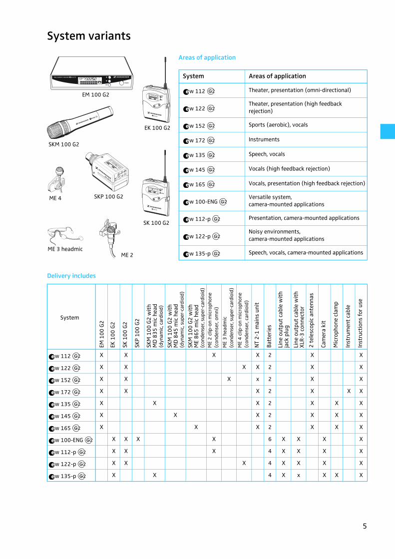
System variants
Areas of application
Delivery includes
EM 100 G2
ME 2
ME 4
EK 100 G2
SKM 100 G2
SKP 100 G2
SK 100 G2
ME 3 headmic
System Areas of application
w 112 Theater, presentation (omni-directional)
w 122Theater, presentation (high feedback rejection)
w 152 Sports (aerobic), vocals
w 172 Instruments
w 135 Speech, vocals
w 145 Vocals (high feedback rejection)
w 165 Vocals, presentation (high feedback rejection)
w 100-ENGVersatile system, camera-mounted applications
w 112-p Presentation, camera-mounted applications
w 122-pNoisy environments, camera-mounted applications
w 135-p Speech, vocals, camera-mounted applications
��
��
��
��
��
��
��
��
��
��
��
w 112 X X X X 2 X X
w 122 X X X X 2 X X
w 152 X X X x 2 X X
w 172 X X X 2 X X X
w 135 X X X 2 X X X
w 145 X X X 2 X X X
w 165 X X X 2 X X X
w 100-ENG X X X X 6 X X X X
w 112-p X X X 4 X X X X
w 122-p X X X 4 X X X X
w 135-p X X 4 X x X X X
System
EM 1
00 G
2
EK 1
00 G
2
SK 1
00 G
2
SKP
100
G2
SKM
100
G2
wit
h M
D 8
35 m
ic h
ead
(dyn
amic
, car
dioi
d)
SKM
100
G2
wit
h M
D 8
45 m
ic h
ead
(dyn
amic
, sup
er-c
ardi
oid)
SKM
100
G2
wit
h M
E 86
5 m
ic h
ead
(con
dens
er, s
uper
-car
dioi
d)M
E2
clip
-on
mic
roph
one
(con
dens
er, o
mni
)
ME
3 h
eadm
ic(c
onde
nser
, sup
er-c
ardi
oid)
ME
4 c
lip-o
n m
icro
phon
e(c
onde
nser
, car
dioi
d)
NT
2-1
mai
ns u
nit
Batt
erie
s
Line
out
put
cabl
e w
ith
jack
plu
g
Line
out
put
cabl
e w
ith
XLR
-3 c
onne
ctor
2 te
lesc
opic
ant
enna
s
Cam
era
kit
Mic
roph
one
clam
p
Inst
rum
ent
cabl
e
Inst
ruct
ions
for
use
��
��
��
��
��
��
��
��
��
��
��

6
Overview of operating controls
EM 100 G2 rack-mount receiver
� � � � � �
� �
� � � � �
� � � � � � � �
�
Operating controls LC display panel
� LC display
� � button (UP)
� � button (DOWN)
� SET button
� POWER button(serves as the ESC (cancel) key in the operating menu)
� Cable grip for power supply DC cable
� DC socket for connection of mains unit (DC IN)
� Audio output (AF OUT BAL),XLR-3M socket, balanced
� Audio output (AF OUT UNBAL),¼” (6.3 mm) jack socket, unbalanced
� Service interface (DATA)
� Antenna input II (ANT II), BNC socket
� Type plate
� Antenna input I (ANT I), BNC socket
� Display for the current channel bank “1 ... 8, U”
� Display for the current channel number “1 ... 4”
� “B.CH“ – abbreviation for channel Bank and CHannel number
� Alphanumeric display
“MHz“ – appears when the frequency is displayed
� Transmitter low battery icon (LOW BAT warning)
� Lock mode icon(lock mode is activated)
� 8-step level display for received RF signal “RF”
8-step level display for received audio signal “AF”, with “PEAK“ warning
“PILOT” display(pilot tone evaluation is activated)
� Diversity display (antenna I or antenna II active)
� “MUTE” display(audio output is muted)
7
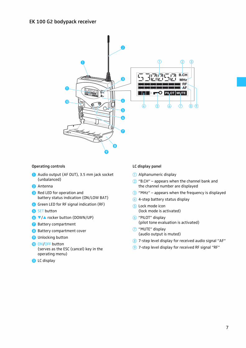
EK 100 G2 bodypack receiver
� �
�
�
�
�
�
�
�
�
�
� � � �
� �
�
�
Operating controls LC display panel
� Audio output (AF OUT), 3.5 mm jack socket (unbalanced)
� Antenna
� Red LED for operation and battery status indication (ON/LOW BAT)
� Green LED for RF signal indication (RF)
� SET button
� �/� rocker button (DOWN/UP)
� Battery compartment
� Battery compartment cover
� Unlocking button
� ON/OFF button(serves as the ESC (cancel) key in the operating menu)
� LC display
� Alphanumeric display
� “B.CH“ – appears when the channel bank and the channel number are displayed
� “MHz“ – appears when the frequency is displayed
� 4-step battery status display
Lock mode icon(lock mode is activated)
� “PILOT” display (pilot tone evaluation is activated)
� “MUTE” display(audio output is muted)
� 7-step level display for received audio signal “AF”
7-step level display for received RF signal “RF”
8
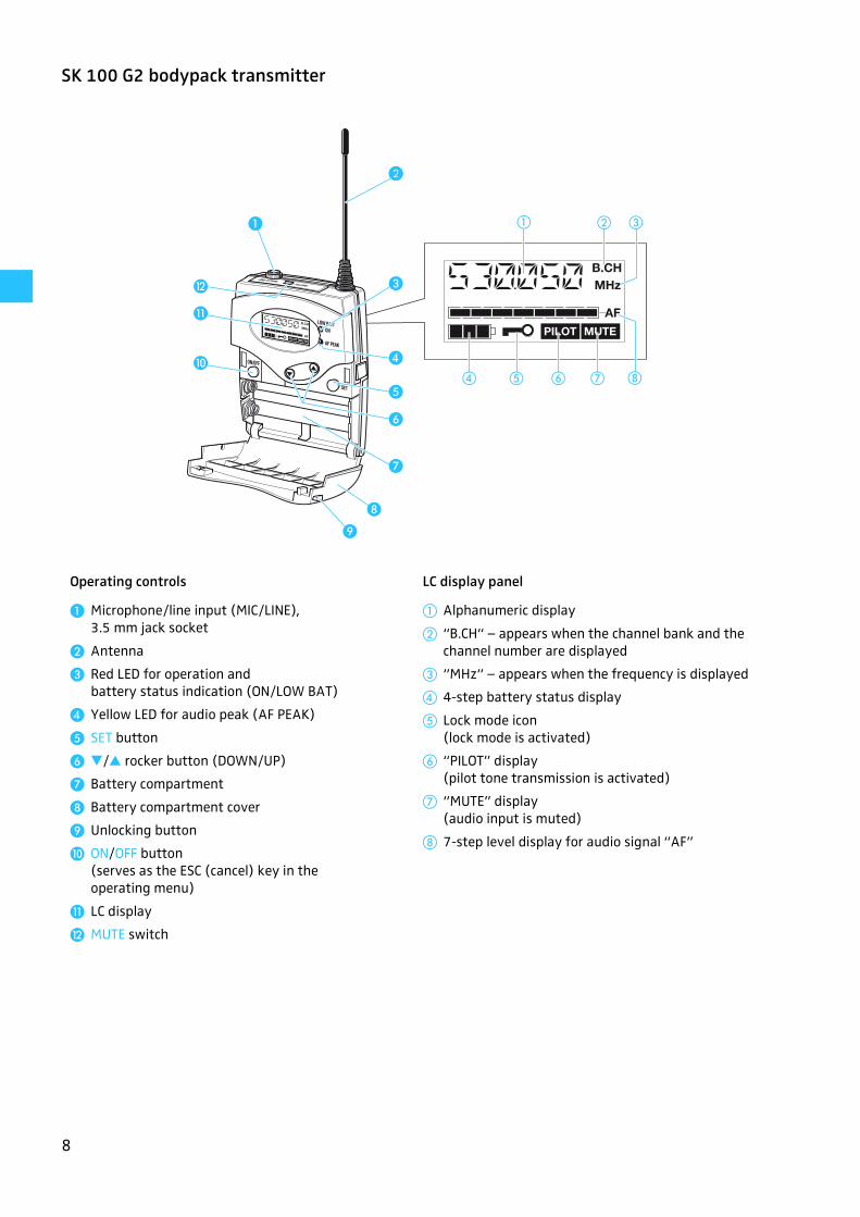
SK 100 G2 bodypack transmitter
� �
�
�
�
�
�
�
�
�
�
�
� � � �
�
�
� �
Operating controls LC display panel
� Microphone/line input (MIC/LINE),3.5 mm jack socket
� Antenna
� Red LED for operation and battery status indication (ON/LOW BAT)
� Yellow LED for audio peak (AF PEAK)
� SET button
� �/� rocker button (DOWN/UP)
� Battery compartment
� Battery compartment cover
� Unlocking button
� ON/OFF button(serves as the ESC (cancel) key in the operating menu)
� LC display
� MUTE switch
� Alphanumeric display
� “B.CH“ – appears when the channel bank and the channel number are displayed
� “MHz“ – appears when the frequency is displayed
� 4-step battery status display
Lock mode icon(lock mode is activated)
� “PILOT” display (pilot tone transmission is activated)
� “MUTE” display(audio input is muted)
� 7-step level display for audio signal “AF”
9
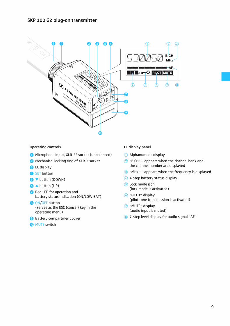
SKP 100 G2 plug-on transmitter
� � � ���
�
�
�
�
� �
� � � �
�
Operating controls LC display panel
� Microphone input, XLR-3F socket (unbalanced)
� Mechanical locking ring of XLR-3 socket
� LC display
� SET button
� � button (DOWN)
� � button (UP)
� Red LED for operation and battery status indication (ON/LOW BAT)
� ON/OFF button(serves as the ESC (cancel) key in the operating menu)
� Battery compartment cover
� MUTE switch
� Alphanumeric display
� “B.CH“ – appears when the channel bank and the channel number are displayed
� “MHz“ – appears when the frequency is displayed
� 4-step battery status display
Lock mode icon(lock mode is activated)
� “PILOT” display (pilot tone transmission is activated)
� “MUTE” display(audio input is muted)
� 7-step level display for audio signal “AF”

10
SKM 100 G2 radiomicrophone
� � � � � ��
�
�
� � � �
�
� �
�
�
�
� �
Operating controls LC display panel
� Sound inlet basket
� Color-coded identification ring for microphone heads
green: MD 835 microphone headblue: MD 845 microphone headred: ME 865 microphone head
� Body of radiomicrophone
� Battery compartment (not visible from outside)
� Display section
� LC display
� Turnable protective cap for operating controls (shown removed)
The following operating controls become acces-sible in turn by turning the protective cap:
� SET button
� � button (DOWN)
� � button (UP)
� Red LED for operation and battery status indication (ON/LOW BAT)
� ON/OFF button(serves as the ESC (cancel) key in the operating menu)
� MUTE switch
� Alphanumeric display
� “B.CH“ – appears when the channel bank and the channel number are displayed
� “MHz“ – appears when the frequency is displayed
� 4-step battery status display
Lock mode icon(lock mode is activated)
� “PILOT” display (pilot tone transmission is activated)
� “MUTE” display(audio input is muted)
� 7-step level display for audio signal “AF”
11
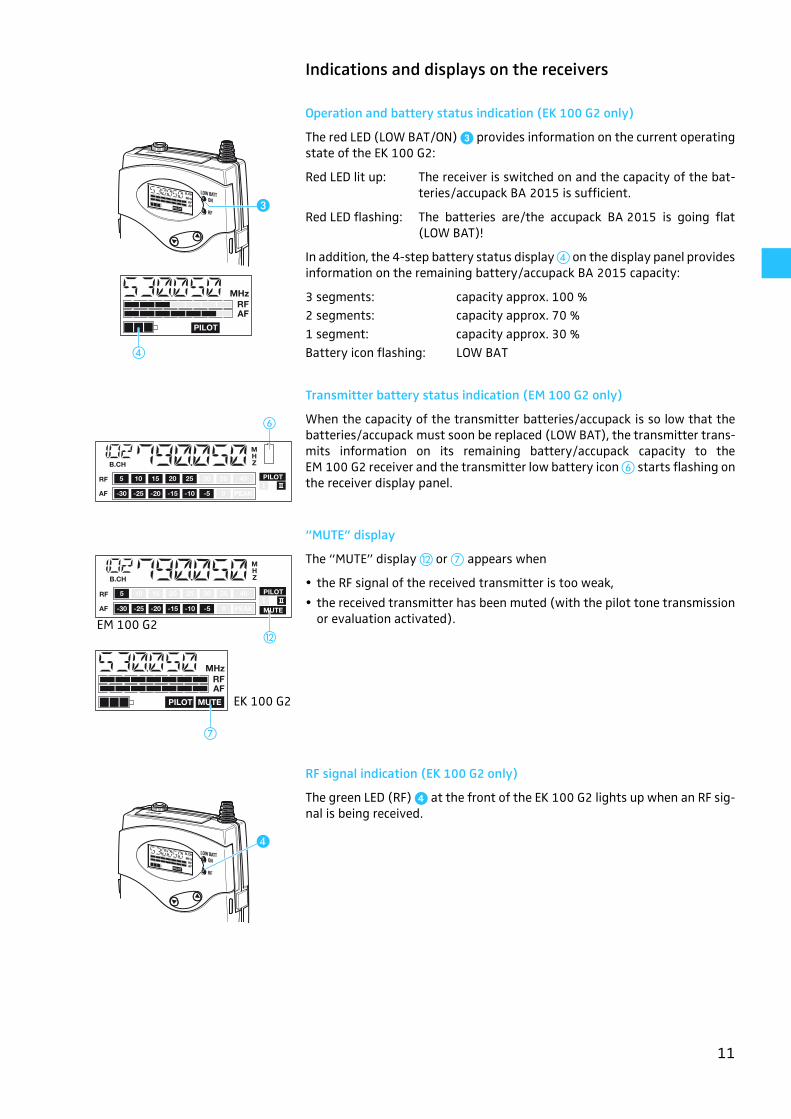
Indications and displays on the receivers
Operation and battery status indication (EK 100 G2 only)
The red LED (LOW BAT/ON) � provides information on the current operatingstate of the EK 100 G2:
Red LED lit up: The receiver is switched on and the capacity of the bat-teries/accupack BA 2015 is sufficient.
Red LED flashing: The batteries are/the accupack BA 2015 is going flat(LOW BAT)!
In addition, the 4-step battery status display � on the display panel providesinformation on the remaining battery/accupack BA 2015 capacity:
Transmitter battery status indication (EM 100 G2 only)
When the capacity of the transmitter batteries/accupack is so low that thebatteries/accupack must soon be replaced (LOW BAT), the transmitter trans-mits information on its remaining battery/accupack capacity to theEM 100 G2 receiver and the transmitter low battery icon � starts flashing onthe receiver display panel.
“MUTE” display
The “MUTE” display � or � appears when
the RF signal of the received transmitter is too weak,
the received transmitter has been muted (with the pilot tone transmissionor evaluation activated).
RF signal indication (EK 100 G2 only)
The green LED (RF) � at the front of the EK 100 G2 lights up when an RF sig-nal is being received.
�
�
3 segments: capacity approx. 100 %2 segments: capacity approx. 70 %1 segment: capacity approx. 30 %Battery icon flashing: LOW BAT
�
�
�
EK 100 G2
EM 100 G2
�
12
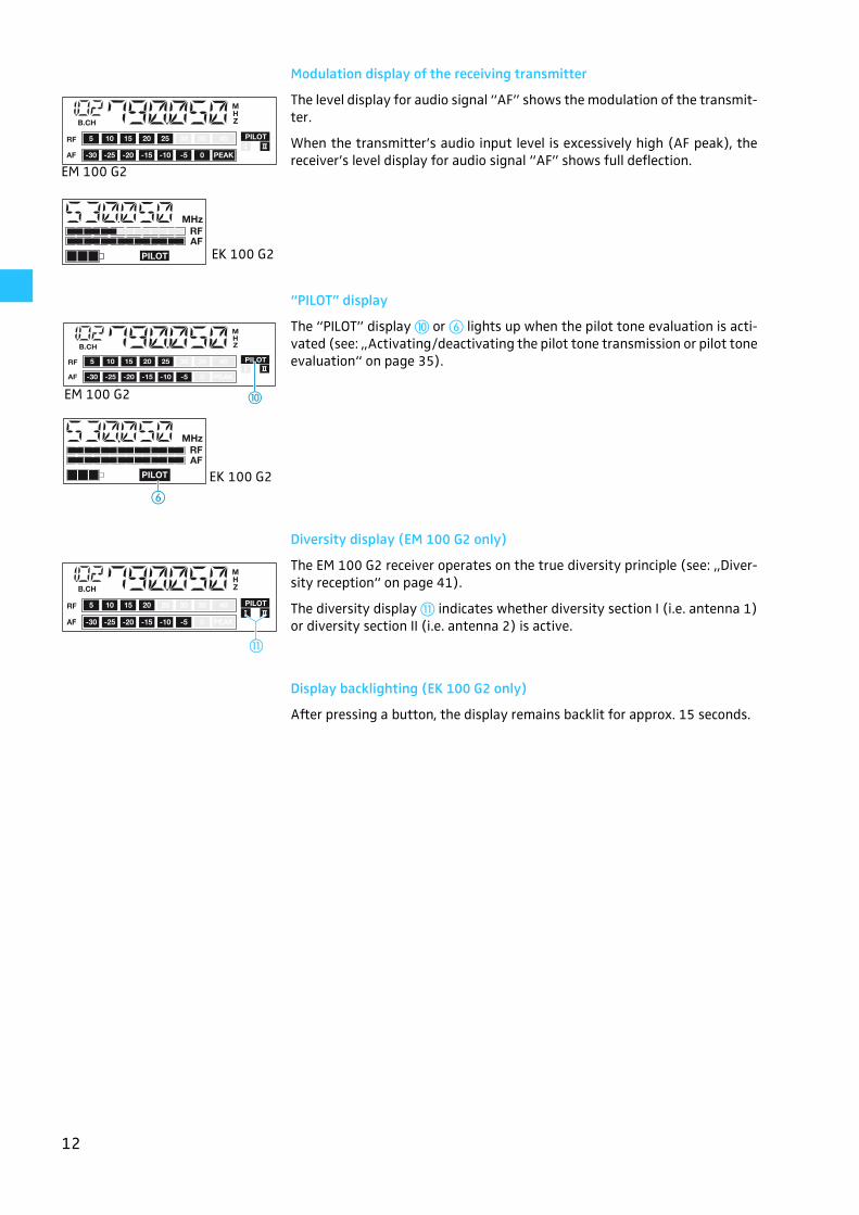
Modulation display of the receiving transmitter
The level display for audio signal “AF” shows the modulation of the transmit-ter.
When the transmitter’s audio input level is excessively high (AF peak), thereceiver’s level display for audio signal “AF” shows full deflection.
“PILOT” display
The “PILOT” display or � lights up when the pilot tone evaluation is acti-vated (see: „Activating/deactivating the pilot tone transmission or pilot toneevaluation“ on page 35).
Diversity display (EM 100 G2 only)
The EM 100 G2 receiver operates on the true diversity principle (see: „Diver-sity reception“ on page 41).
The diversity display � indicates whether diversity section I (i.e. antenna 1)or diversity section II (i.e. antenna 2) is active.
Display backlighting (EK 100 G2 only)
After pressing a button, the display remains backlit for approx. 15 seconds.
EM 100 G2
EK 100 G2
EK 100 G2
�
EM 100 G2
EK 100 G2
�
13
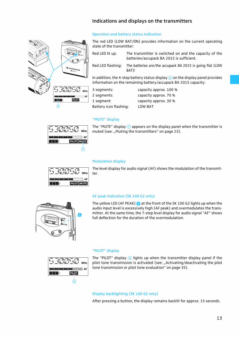
Indications and displays on the transmitters
Operation and battery status indication
The red LED (LOW BAT/ON) provides information on the current operatingstate of the transmitter:
Red LED lit up: The transmitter is switched on and the capacity of thebatteries/accupack BA 2015 is sufficient.
Red LED flashing: The batteries are/the accupack BA 2015 is going flat (LOWBAT)!
In addition, the 4-step battery status display � on the display panel providesinformation on the remaining battery/accupack BA 2015 capacity:
“MUTE” display
The “MUTE” display � appears on the display panel when the transmitter ismuted (see: „Muting the transmitters“ on page 23).
Modulation display
The level display for audio signal (AF) shows the modulation of the transmit-ter.
AF peak indication (SK 100 G2 only)
The yellow LED (AF PEAK) � at the front of the SK 100 G2 lights up when theaudio input level is excessively high (AF peak) and overmodulates the trans-mitter. At the same time, the 7-step level display for audio signal “AF” showsfull deflection for the duration of the overmodulation.
“PILOT” display
The “PILOT” display � lights up when the transmitter display panel if thepilot tone transmission is activated (see: „Activating/deactivating the pilottone transmission or pilot tone evaluation“ on page 35).
Display backlighting (SK 100 G2 only)
After pressing a button, the display remains backlit for approx. 15 seconds.
�
3 segments: capacity approx. 100 %2 segments: capacity approx. 70 %1 segment: capacity approx. 30 %Battery icon flashing: LOW BAT
�
�
�
14
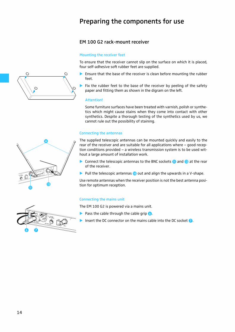
Preparing the components for use
EM 100 G2 rack-mount receiver
Mounting the receiver feet
To ensure that the receiver cannot slip on the surface on which it is placed,four self-adhesive soft rubber feet are supplied.
� Ensure that the base of the receiver is clean before mounting the rubberfeet.
� Fix the rubber feet to the base of the receiver by peeling of the safetypaper and fitting them as shown in the digram on the left.
Attention!
Some furniture surfaces have been treated with varnish, polish or synthe-tics which might cause stains when they come into contact with othersynthetics. Despite a thorough testing of the synthetics used by us, wecannot rule out the possibility of staining.
Connecting the antennas
The supplied telescopic antennas can be mounted quickly and easily to therear of the receiver and are suitable for all applications where – good recep-tion conditions provided – a wireless transmission system is to be used wit-hout a large amount of installation work.
� Connect the telescopic antennas to the BNC sockets � and � at the rearof the receiver.
� Pull the telescopic antennas � out and align the upwards in a V-shape.
Use remote antennas when the receiver position is not the best antenna posi-tion for optimum reception.
Connecting the mains unit
The EM 100 G2 is powered via a mains unit.
� Pass the cable through the cable grip �.
� Insert the DC connector on the mains cable into the DC socket �.
�
�
�
� �
15
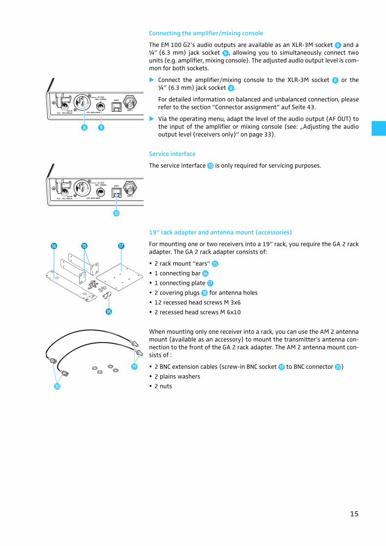
Connecting the amplifier/mixing console
The EM 100 G2’s audio outputs are available as an XLR-3M socket � and a¼” (6.3 mm) jack socket �, allowing you to simultaneously connect twounits (e.g. amplifier, mixing console). The adjusted audio output level is com-mon for both sockets.
� Connect the amplifier/mixing console to the XLR-3M socket � or the¼” (6.3 mm) jack socket �.
For detailed information on balanced and unbalanced connection, pleaserefer to the section “Connector assignment” auf Seite 43.
� Via the operating menu, adapt the level of the audio output (AF OUT) tothe input of the amplifier or mixing console (see: „Adjusting the audiooutput level (receivers only)“ on page 33).
Service interface
The service interface � is only required for servicing purposes.
19” rack adapter and antenna mount (accessories)
For mounting one or two receivers into a 19” rack, you require the GA 2 rackadapter. The GA 2 rack adapter consists of:
2 rack mount “ears” !
1 connecting bar "
1 connecting plate #
2 covering plugs $ for antenna holes
12 recessed head screws M 3x6
2 recessed head screws M 6x10
When mounting only one receiver into a rack, you can use the AM 2 antennamount (available as an accessory) to mount the transmitter’s antenna con-nection to the front of the GA 2 rack adapter. The AM 2 antenna mount con-sists of :
2 BNC extension cables (screw-in BNC socket % to BNC connector &)
2 plains washers
2 nuts
� �
�
" #
$
!
&
%
16
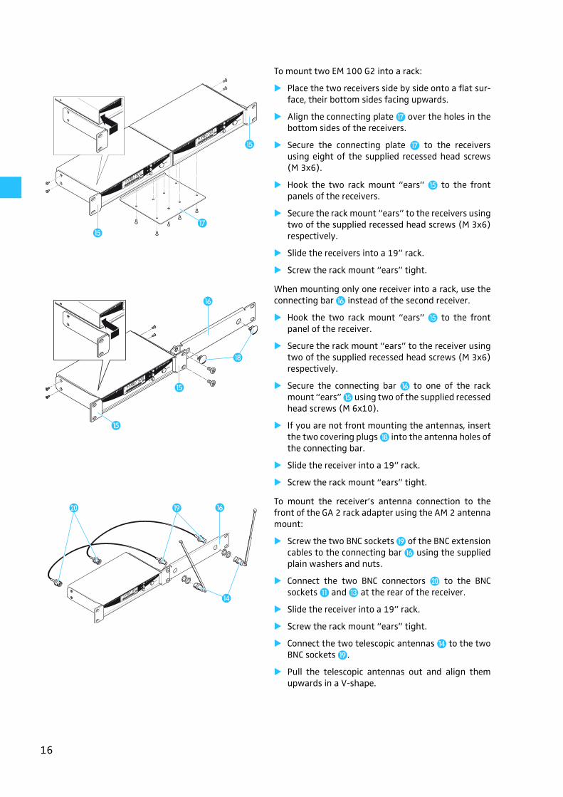
To mount two EM 100 G2 into a rack:
� Place the two receivers side by side onto a flat sur-face, their bottom sides facing upwards.
� Align the connecting plate # over the holes in thebottom sides of the receivers.
� Secure the connecting plate # to the receiversusing eight of the supplied recessed head screws(M 3x6).
� Hook the two rack mount “ears” ! to the frontpanels of the receivers.
� Secure the rack mount “ears” to the receivers usingtwo of the supplied recessed head screws (M 3x6)respectively.
� Slide the receivers into a 19” rack.
� Screw the rack mount “ears” tight.
When mounting only one receiver into a rack, use theconnecting bar " instead of the second receiver.
� Hook the two rack mount “ears” ! to the frontpanel of the receiver.
� Secure the rack mount “ears” to the receiver usingtwo of the supplied recessed head screws (M 3x6)respectively.
� Secure the connecting bar " to one of the rackmount “ears” ! using two of the supplied recessedhead screws (M 6x10).
� If you are not front mounting the antennas, insertthe two covering plugs $ into the antenna holes ofthe connecting bar.
� Slide the receiver into a 19” rack.
� Screw the rack mount “ears” tight.
To mount the receiver’s antenna connection to thefront of the GA 2 rack adapter using the AM 2 antennamount:
� Screw the two BNC sockets % of the BNC extensioncables to the connecting bar " using the suppliedplain washers and nuts.
� Connect the two BNC connectors & to the BNCsockets � and � at the rear of the receiver.
� Slide the receiver into a 19” rack.
� Screw the rack mount “ears” tight.
� Connect the two telescopic antennas � to the twoBNC sockets %.
� Pull the telescopic antennas out and align themupwards in a V-shape.
!
!
#
"
!
!
$
& % "
�
17
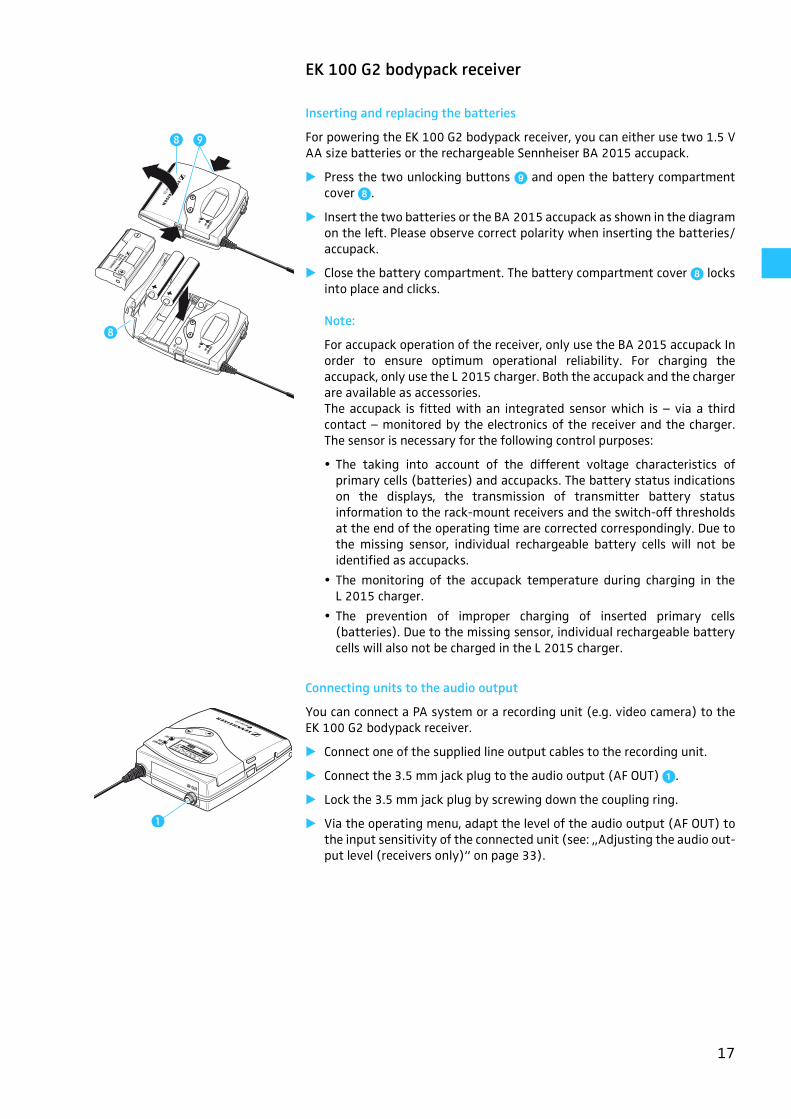
EK 100 G2 bodypack receiver
Inserting and replacing the batteries
For powering the EK 100 G2 bodypack receiver, you can either use two 1.5 VAA size batteries or the rechargeable Sennheiser BA 2015 accupack.
� Press the two unlocking buttons � and open the battery compartmentcover �.
� Insert the two batteries or the BA 2015 accupack as shown in the diagramon the left. Please observe correct polarity when inserting the batteries/accupack.
� Close the battery compartment. The battery compartment cover � locksinto place and clicks.
Note:
For accupack operation of the receiver, only use the BA 2015 accupack Inorder to ensure optimum operational reliability. For charging theaccupack, only use the L 2015 charger. Both the accupack and the chargerare available as accessories.The accupack is fitted with an integrated sensor which is – via a thirdcontact – monitored by the electronics of the receiver and the charger.The sensor is necessary for the following control purposes:
The taking into account of the different voltage characteristics ofprimary cells (batteries) and accupacks. The battery status indicationson the displays, the transmission of transmitter battery statusinformation to the rack-mount receivers and the switch-off thresholdsat the end of the operating time are corrected correspondingly. Due tothe missing sensor, individual rechargeable battery cells will not beidentified as accupacks.
The monitoring of the accupack temperature during charging in theL 2015 charger.
The prevention of improper charging of inserted primary cells(batteries). Due to the missing sensor, individual rechargeable batterycells will also not be charged in the L 2015 charger.
Connecting units to the audio output
You can connect a PA system or a recording unit (e.g. video camera) to theEK 100 G2 bodypack receiver.
� Connect one of the supplied line output cables to the recording unit.
� Connect the 3.5 mm jack plug to the audio output (AF OUT) '.
� Lock the 3.5 mm jack plug by screwing down the coupling ring.
� Via the operating menu, adapt the level of the audio output (AF OUT) tothe input sensitivity of the connected unit (see: „Adjusting the audio out-put level (receivers only)“ on page 33).
��
�
�
18
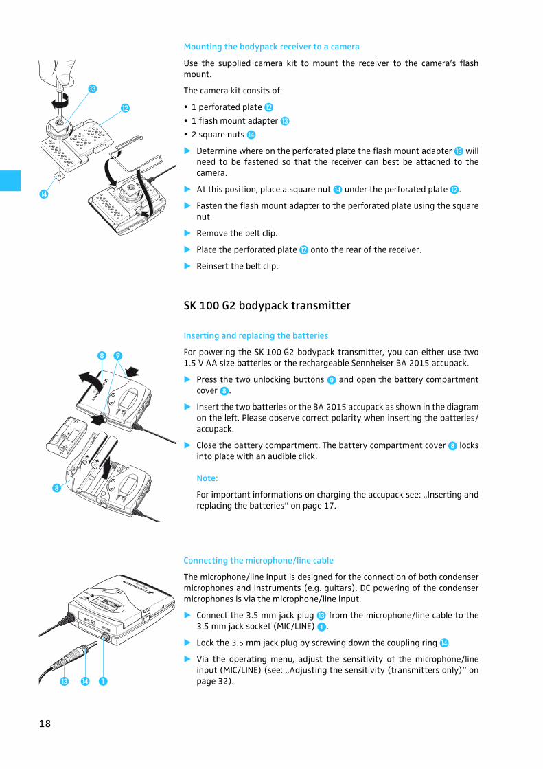
Mounting the bodypack receiver to a camera
Use the supplied camera kit to mount the receiver to the camera’s flashmount.
The camera kit consits of:
1 perforated plate �
1 flash mount adapter �
2 square nuts �
� Determine where on the perforated plate the flash mount adapter � willneed to be fastened so that the receiver can best be attached to thecamera.
� At this position, place a square nut � under the perforated plate �.
� Fasten the flash mount adapter to the perforated plate using the squarenut.
� Remove the belt clip.
� Place the perforated plate � onto the rear of the receiver.
� Reinsert the belt clip.
SK 100 G2 bodypack transmitter
Inserting and replacing the batteries
For powering the SK 100 G2 bodypack transmitter, you can either use two1.5 V AA size batteries or the rechargeable Sennheiser BA 2015 accupack.
� Press the two unlocking buttons � and open the battery compartmentcover �.
� Insert the two batteries or the BA 2015 accupack as shown in the diagramon the left. Please observe correct polarity when inserting the batteries/accupack.
� Close the battery compartment. The battery compartment cover � locksinto place with an audible click.
Note:
For important informations on charging the accupack see: „Inserting andreplacing the batteries“ on page 17.
Connecting the microphone/line cable
The microphone/line input is designed for the connection of both condensermicrophones and instruments (e.g. guitars). DC powering of the condensermicrophones is via the microphone/line input.
� Connect the 3.5 mm jack plug � from the microphone/line cable to the3.5 mm jack socket (MIC/LINE) '.
� Lock the 3.5 mm jack plug by screwing down the coupling ring �.
� Via the operating menu, adjust the sensitivity of the microphone/lineinput (MIC/LINE) (see: „Adjusting the sensitivity (transmitters only)“ onpage 32).
�
�
�
��
�
���
19
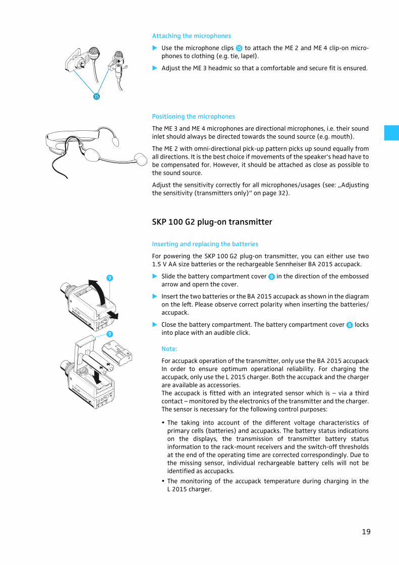
Attaching the microphones
� Use the microphone clips ! to attach the ME 2 and ME 4 clip-on micro-phones to clothing (e.g. tie, lapel).
� Adjust the ME 3 headmic so that a comfortable and secure fit is ensured.
Positioning the microphones
The ME 3 and ME 4 microphones are directional microphones, i.e. their soundinlet should always be directed towards the sound source (e.g. mouth).
The ME 2 with omni-directional pick-up pattern picks up sound equally fromall directions. It is the best choice if movements of the speaker’s head have tobe compensated for. However, it should be attached as close as possible tothe sound source.
Adjust the sensitivity correctly for all microphones/usages (see: „Adjustingthe sensitivity (transmitters only)“ on page 32).
SKP 100 G2 plug-on transmitter
Inserting and replacing the batteries
For powering the SKP 100 G2 plug-on transmitter, you can either use two1.5 V AA size batteries or the rechargeable Sennheiser BA 2015 accupack.
� Slide the battery compartment cover � in the direction of the embossedarrow and opern the cover.
� Insert the two batteries or the BA 2015 accupack as shown in the diagramon the left. Please observe correct polarity when inserting the batteries/accupack.
� Close the battery compartment. The battery compartment cover � locksinto place with an audible click.
Note:
For accupack operation of the transmitter, only use the BA 2015 accupackIn order to ensure optimum operational reliability. For charging theaccupack, only use the L 2015 charger. Both the accupack and the chargerare available as accessories.The accupack is fitted with an integrated sensor which is – via a thirdcontact – monitored by the electronics of the transmitter and the charger.The sensor is necessary for the following control purposes:
The taking into account of the different voltage characteristics ofprimary cells (batteries) and accupacks. The battery status indicationson the displays, the transmission of transmitter battery statusinformation to the rack-mount receivers and the switch-off thresholdsat the end of the operating time are corrected correspondingly. Due tothe missing sensor, individual rechargeable battery cells will not beidentified as accupacks.
The monitoring of the accupack temperature during charging in theL 2015 charger.
!
�
�
20
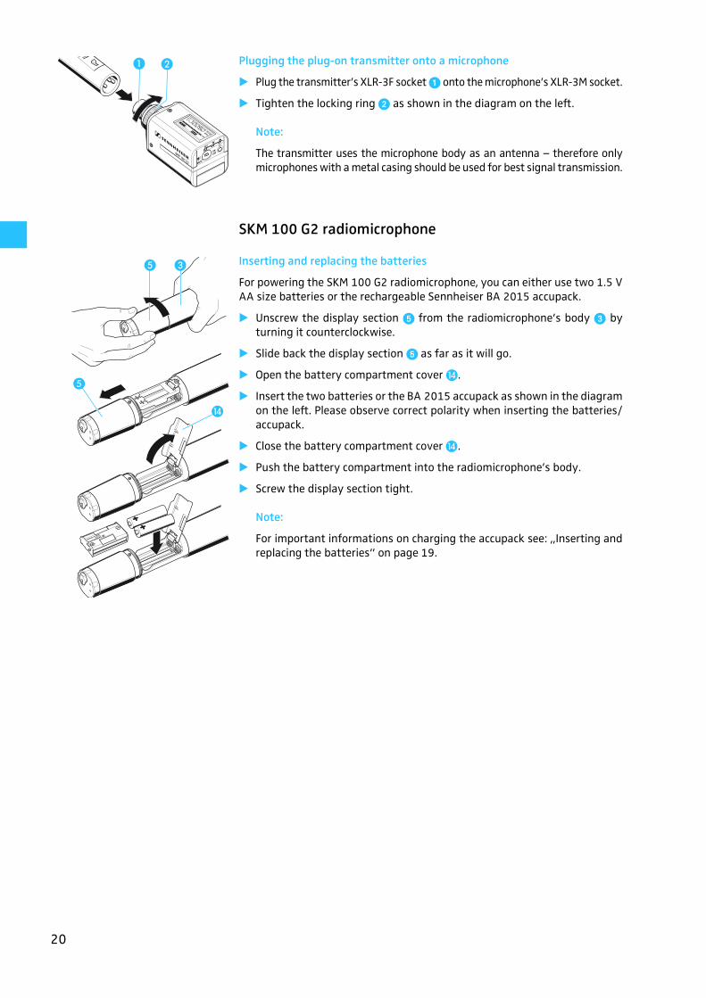
Plugging the plug-on transmitter onto a microphone
� Plug the transmitter’s XLR-3F socket ' onto the microphone’s XLR-3M socket.
� Tighten the locking ring ( as shown in the diagram on the left.
Note:
The transmitter uses the microphone body as an antenna – therefore onlymicrophones with a metal casing should be used for best signal transmission.
SKM 100 G2 radiomicrophone
Inserting and replacing the batteries
For powering the SKM 100 G2 radiomicrophone, you can either use two 1.5 VAA size batteries or the rechargeable Sennheiser BA 2015 accupack.
� Unscrew the display section ) from the radiomicrophone’s body � byturning it counterclockwise.
� Slide back the display section ) as far as it will go.
� Open the battery compartment cover �.
� Insert the two batteries or the BA 2015 accupack as shown in the diagramon the left. Please observe correct polarity when inserting the batteries/accupack.
� Close the battery compartment cover �.
� Push the battery compartment into the radiomicrophone’s body.
� Screw the display section tight.
Note:
For important informations on charging the accupack see: „Inserting andreplacing the batteries“ on page 19.
� �
�
�
� �
21
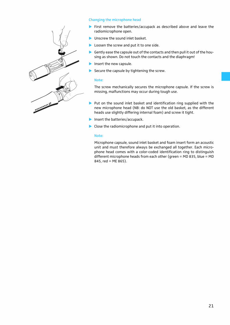
Changing the microphone head
� First remove the batteries/accupack as described above and leave theradiomicrophone open.
� Unscrew the sound inlet basket.
� Loosen the screw and put it to one side.
� Gently ease the capsule out of the contacts and then pull it out of the hou-sing as shown. Do not touch the contacts and the diaphragm!
� Insert the new capsule.
� Secure the capsule by tightening the screw.
Note:
The screw mechanically secures the microphone capsule. If the screw ismissing, malfunctions may occur during tough use.
� Put on the sound inlet basket and identification ring supplied with thenew microphone head (NB: do NOT use the old basket, as the differentheads use slightly differing internal foam) and screw it tight.
� Insert the batteries/accupack.
� Close the radiomicrophone and put it into operation.
Note:
Microphone capsule, sound inlet basket and foam insert form an acousticunit and must therefore always be exchanged all together. Each micro-phone head comes with a color-coded identification ring to distinguishdifferent microphone heads from each other (green = MD 835, blue = MD845, red = ME 865).
22
Using the components
Switching the components on/off
The ew 100 G2 transmitters and receivers can only be switched off when thestandard display is shown on the display panel. Within the operating menu,the ON/OFF button or the POWER button (EM 100 G2 only) serves as the ESC(cancel) key, i.e you cancel your entry and return to the standard display.
Note:
Remove the batteries or the accupack when the units will not be used forextended periods of time.
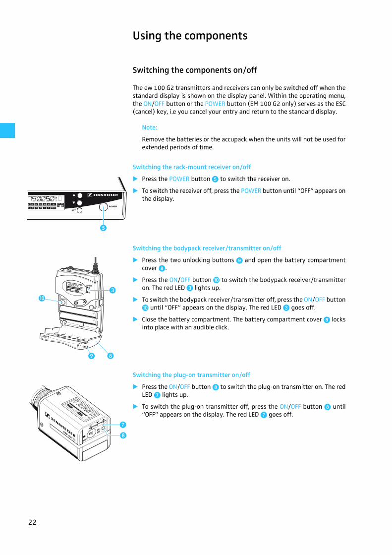
Switching the rack-mount receiver on/off
� Press the POWER button � to switch the receiver on.
� To switch the receiver off, press the POWER button until “OFF” appears onthe display.
Switching the bodypack receiver/transmitter on/off
� Press the two unlocking buttons � and open the battery compartmentcover �.
� Press the ON/OFF button � to switch the bodypack receiver/transmitteron. The red LED � lights up.
� To switch the bodypack receiver/transmitter off, press the ON/OFF button� until “OFF” appears on the display. The red LED � goes off.
� Close the battery compartment. The battery compartment cover � locksinto place with an audible click.
Switching the plug-on transmitter on/off
� Press the ON/OFF button � to switch the plug-on transmitter on. The redLED * lights up.
� To switch the plug-on transmitter off, press the ON/OFF button � until“OFF” appears on the display. The red LED * goes off.
�
� �
��
�
�
23
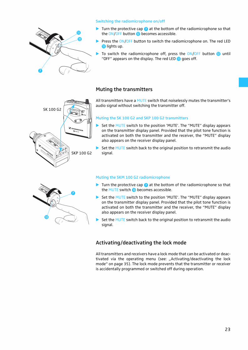
Switching the radiomicrophone on/off
� Turn the protective cap * at the bottom of the radiomicrophone so thatthe ON/OFF button � becomes accessible.
� Press the ON/OFF button to switch the radiomicrophone on. The red LED� lights up.
� To switch the radiomicrophone off, press the ON/OFF button � until“OFF” appears on the display. The red LED � goes off.
Muting the transmitters
All transmitters have a MUTE switch that noiselessly mutes the transmitter’saudio signal without switching the transmitter off.
Muting the SK 100 G2 and SKP 100 G2 transmitters
� Set the MUTE switch to the position ’MUTE’. The “MUTE” display appearson the transmitter display panel. Provided that the pilot tone function isactivated on both the transmitter and the receiver, the “MUTE” displayalso appears on the receiver display panel.
� Set the MUTE switch back to the original position to retransmit the audiosignal.
Muting the SKM 100 G2 radiomicrophone
� Turn the protective cap * at the bottom of the radiomicrophone so thatthe MUTE switch � becomes accessible.
� Set the MUTE switch to the position ’MUTE’. The “MUTE” display appearson the transmitter display panel. Provided that the pilot tone function isactivated on both the transmitter and the receiver, the “MUTE” displayalso appears on the receiver display panel.
� Set the MUTE switch back to the original position to retransmit the audiosignal.
Activating/deactivating the lock mode
All transmitters and receivers have a lock mode that can be activated or deac-tivated via the operating menu (see: „Activating/deactivating the lockmode“ on page 35). The lock mode prevents that the transmitter or receiveris accidentally programmed or switched off during operation.
�
�
�
SKP 100 G2
SK 100 G2
�
�
24
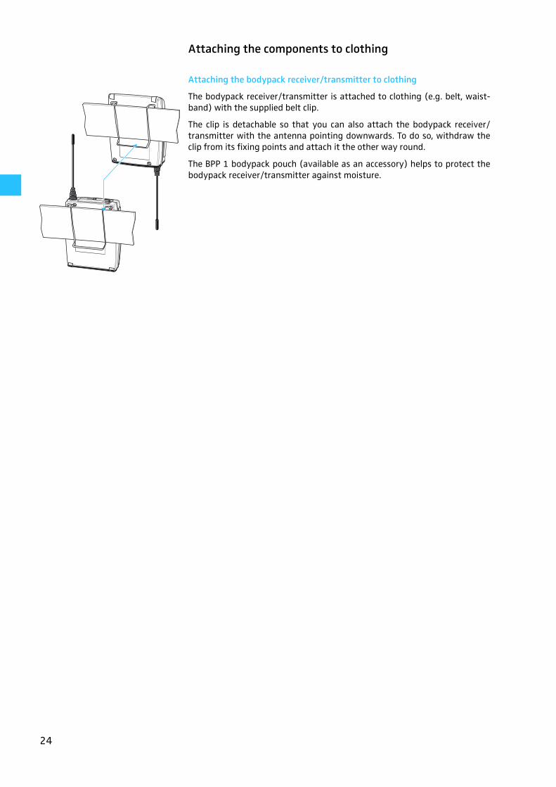
Attaching the components to clothing
Attaching the bodypack receiver/transmitter to clothing
The bodypack receiver/transmitter is attached to clothing (e.g. belt, waist-band) with the supplied belt clip.
The clip is detachable so that you can also attach the bodypack receiver/transmitter with the antenna pointing downwards. To do so, withdraw theclip from its fixing points and attach it the other way round.
The BPP 1 bodypack pouch (available as an accessory) helps to protect thebodypack receiver/transmitter against moisture.
25
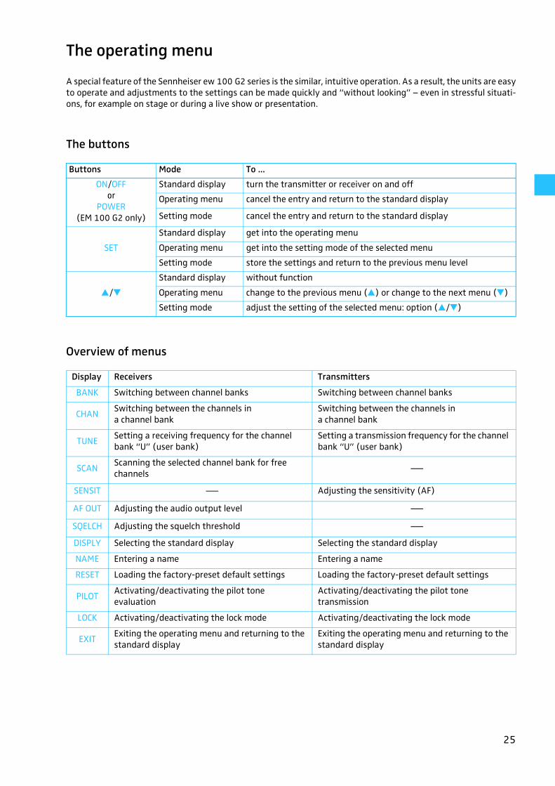
The operating menu
A special feature of the Sennheiser ew 100 G2 series is the similar, intuitive operation. As a result, the units are easyto operate and adjustments to the settings can be made quickly and “without looking” – even in stressful situati-ons, for example on stage or during a live show or presentation.
The buttons
Overview of menus
Buttons Mode To ...
ON/OFFor
POWER (EM 100 G2 only)
Standard display turn the transmitter or receiver on and off
Operating menu cancel the entry and return to the standard display
Setting mode cancel the entry and return to the standard display
SET
Standard display get into the operating menu
Operating menu get into the setting mode of the selected menu
Setting mode store the settings and return to the previous menu level
�/�Standard display without function
Operating menu change to the previous menu (�) or change to the next menu (�)
Setting mode adjust the setting of the selected menu: option (�/�)
Display Receivers Transmitters
BANK Switching between channel banks Switching between channel banks
CHANSwitching between the channels ina channel bank
Switching between the channels in a channel bank
TUNE Setting a receiving frequency for the channel bank “U” (user bank)
Setting a transmission frequency for the channel bank “U” (user bank)
SCANScanning the selected channel bank for free channels ⎯
SENSIT ⎯ Adjusting the sensitivity (AF)
AF OUT Adjusting the audio output level ⎯SQELCH Adjusting the squelch threshold ⎯DISPLY Selecting the standard display Selecting the standard display
NAME Entering a name Entering a name
RESET Loading the factory-preset default settings Loading the factory-preset default settings
PILOTActivating/deactivating the pilot tone evaluation
Activating/deactivating the pilot tone transmission
LOCK Activating/deactivating the lock mode Activating/deactivating the lock mode
EXITExiting the operating menu and returning to the standard display
Exiting the operating menu and returning to the standard display

26
Working with the operating menu
By way of example of the “TUNE” menu, this section describes how to use theoperating menu.
After switching the unit on, the standard display is shown on the displaypanel.
Getting into the operating menu
� Press the SET button to get from the standard display into the operatingmenu. The last menu selected flashes on the display.
Selecting a menu
� Press the �/� buttons to select a menu.
� Press the SET button to get into the setting mode of the selected menu.The current setting that can be adjusted flashes on the display.
Adjusting a setting
� Press the �/� buttons to adjust the setting. By briefly pressing the �/�buttons, the display jumps either forwards or backwards to the next set-ting. In the “CHAN”, “TUNE” and “NAME” menu, the �/� buttons featurea “fast search” function. If you hold down a button, the display cycles con-tinuously. The “fast search” function allows you to get fast and easily toyour desired setting. The new setting flashes on the display until it isstored.
Storing a setting
� Press the SET button to store the setting. “STORED” appears on the dis-play, indicating that the setting has been stored. The display then returnsto the previous menu level.
With most menus, new settings become effective immediately withouthaving to be stored. An exception are the “BANK”, “CHAN”, “TUNE” and“RESET” menus of the transmitters and the “RESET” menu of the recei-vers. With these menus, new settings only become effective after theyhave been stored (“STORED” appears on the display, indicating that thesetting has been stored).
Exiting the operating menu
� Select the “EXIT” menu to exit the operating menu and to return to thestandard display.
When you have entered the operating menu, the ON/OFF button or thePOWER button (EM 100 G2 receiver only) serves as the ESC (cancel) key,i.e. by briefly pressing the ON/OFF or POWER button, you cancel your entryand return to the standard display.
EM 100 G2
EK 100 G2
Trans-mitters

27
Operating menu of the receivers
SET
Changing the channel
STORED
CHAN 790.025 0101B . CH1. 790.100 0404
B . CH1.SET
Current channel (display depends on "DISPLY" setting)
� � / �: Channel 01...04
SET: Stores the setting
BANKChanging the channel bank
BANK 1 BANK USET
Current channel bank � � / �: 1...8, U (User Bank)
SET: Stores the setting
STORED
AF OUTSetting the audio output level
LEV +1818 LEV -24 SET
Current audio output level
� � / �: (in steps of 6 dB): EM 100 G2:+18...0...-24 dB EK 100 G2: +12...0...-30 dB
SET: Stores the setting
SQELCHSetting the squelch threshold
SET
Current squelch threshold
� � / �: LO, MID, HI
SET: Stores the setting
SQ LOLO SQ HIHI
STORED
DISPLY
TUNESetting the frequency for channel bank "U"
Current frequency on the selected channel
� � / �: Receiving frequency in steps of 25 kHz
SET: Stores the setting
790.025790.025 791.125791.125SET
STORED
SET
U. U.SCAN START Scanning the selected channel bank for free channels
� � / �: CLEAR, START
Start scan = STARTSET: Scans the selected channel bank for free channels
CLEAR
Delete result = CLEARSET: Releases locked channels
04 CH FREE
STORED
SET
STORED
EXIT
28
SQELCH
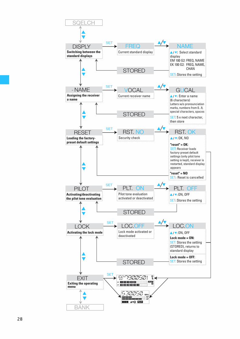
RESETLoading the factory-preset default settings
SET
Security check � � / �: OK, NO
"reset" = OK: SET: Receiver loads factory-preset default settings (only pilot tone setting is kept), receiver is restarted, standard display appears
RST. NONO RST. OKOK
PILOTActivating/deactivating the pilot tone evaluation
SET
Pilot tone evaluation activated or deactivated
� � / �: ON, OFF
SET: Stores the setting
� � / �: ON, OFFLock mode = ON: SET: Stores the setting (STORED), returns to standard display
Lock mode = OFF: SET: Stores the setting
PLT. ONON PLT. OFFOFF
LOCKActivating the lock mode
SET
SET
Lock mode activated or deactivated
LOC.OFFOFF LOC.ONON
EXITExiting the operating menu
STORED
NAMESET
Current receiver nameAssigning the receiver a name
� � / �: Enter a name (6 characters) Letters w/o pronounciation marks, numbers from 0...9, special characters, spaces
SET: 5 x next character, then store
VOCAL GUCAL
DISPLYSwitching between the standard displays
SET
Current standard display � � / �: Select standard display EM 100 G2: FREQ, NAME EK 100 G2: FREQ, NAME, CHAN
SET: Stores the setting
FREQFREQ NAMENAME
STORED
STORED
STORED
BANK
"reset" = NOSET: Reset is cancelled
29
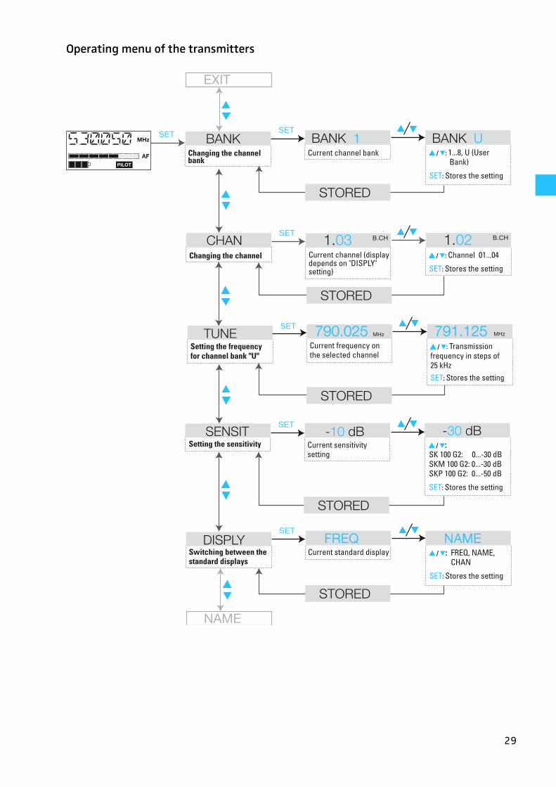
Operating menu of the transmitters
SET BANKChanging the channel bank
BANK 1 BANK USET
Current channel bank � � / �: 1...8, U (User Bank)
SET: Stores the setting
STORED
STORED
CHAN 1.03 B.CHSET
Current channel (display depends on "DISPLY" setting)
Changing the channel � � / �: Channel 01...04
SET: Stores the setting
SENSITSetting the sensitivity
-10 dB -30 dB SET
Current sensitivity setting
� � / �: SK 100 G2: 0...-30 dB SKM 100 G2: 0...-30 dB SKP 100 G2: 0...-50 dB
SET: Stores the setting
DISPLYSwitching between the standard displays
SET
Current standard display � � / �: FREQ, NAME, CHAN
SET: Stores the setting
FREQFREQ NAMENAME
STORED
STORED
TUNECurrent frequency on the selected channel
� � / �: Transmission frequency in steps of 25 kHzSET: Stores the setting
790.025790.025 791.125791.125SET
STORED
1.02 B.CH
MHz MHz
NAME
Setting the frequency for channel bank "U"
EXIT
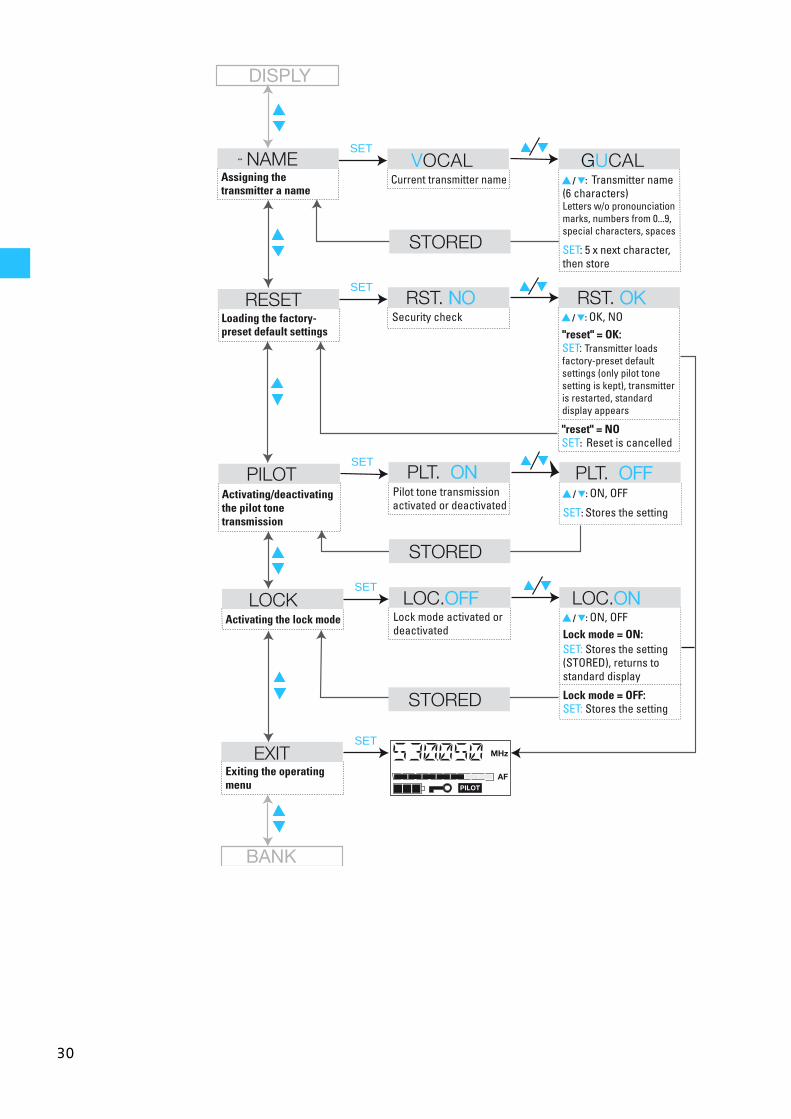
30
DISPLY
PILOTActivating/deactivating the pilot tone transmission
SET
Pilot tone transmission activated or deactivated
� � / �: ON, OFF
SET: Stores the setting
PLT. ONON PLT. OFFOFF
LOCKActivating the lock mode
SET
SET
Lock mode activated or deactivated
LOC.OFFOFF LOC.ONON
EXITExiting the operating menu
STORED
STORED
BANK
RESETLoading the factory-preset default settings
SET
Security checkRST. NONO RST. OKOK
NAMESET
Current transmitter nameAssigning the transmitter a name
� � / �: Transmitter name (6 characters) Letters w/o pronounciation marks, numbers from 0...9, special characters, spaces
SET: 5 x next character, then store
VOCAL GUCAL
STORED
� � / �: OK, NO"reset" = OK: SET: Transmitter loads factory-preset default settings (only pilot tone setting is kept), transmitter is restarted, standard display appears
"reset" = NOSET: Reset is cancelled
� � / �: ON, OFFLock mode = ON: SET: Stores the setting (STORED), returns to standard display
Lock mode = OFF: SET: Stores the setting
31
Adjustment tips for the operating menu
Switching between channel banks
BANK Via the “BANK” menu, you can switch between the nine channel banks of thetransmitters and receivers. The channel banks “1” to “8” have fourswitchable channels that are factory-preset to a transmission/receiving fre-quency (see: „The channel bank system“ on page 4). The channel bank “U”(user bank) has four switchable channels to store your selection out of 1440transmission/receiving frequencies that are freely selectable within the pre-set frequency range.
When switching from one channel bank to another, the channel with thelowest channel number is automatically displayed. If, during the last scan ofthis channel bank, an interfering frequency was detected on the channel withthe lowest channel number (see: „Scanning the channel banks for free chan-nels (receivers only)“ on page 31), the receiver display panel automaticallydisplays the next free channel.
Switching between the channels in a channel bank
CHAN Via the “CHAN” menu, you can switch between the four channels in a channelbank.
Always set the transmitter and the receiver of a transmission link to the samechannel. After scanning a channel bank (see: „Scanning the channel banks forfree channels (receivers only)“ on page 31), only the free channels are dis-played. Set the transmitter to one of the free channels.
Selecting the frequencies to be storedin the channel bank “U”
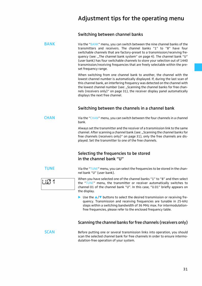
TUNE Via the “TUNE” menu, you can select the frequencies to be stored in the chan-nel bank “U” (user bank).
When you have selected one of the channel banks “1” to “8” and then selectthe “TUNE” menu, the transmitter or receiver automatically switches tochannel 01 of the channel bank “U”. In this case, “U.01” briefly appears onthe display.
� Use the �/� buttons to select the desired transmission or receiving fre-quency. Transmission and receiving frequencies are tunable in 25-kHzsteps within a switching bandwidth of 36 MHz max. For intermodulation-free frequencies, please refer to the enclosed frequency table.
Scanning the channel banks for free channels (receivers only)
SCAN Before putting one or several transmission links into operation, you shouldscan the selected channel bank for free channels In order to ensure intermo-dulation-free operation of your system.
32
Starting the scan and storing the scan result
� Before starting the scan, switch all transmitters of your system off, sincechannels used by switched-on transmitters will not be displayed as “freechannels”.
� Select the “SCAN” menu.
� Select “START” and confirm your selection by pressing the SET button.After the scan is completed, the number of free channels is displayed.Pressing the SET button once more will store the scan result and lock allchannels that are used or subject to interference.
Releasing locked channels
� Select the “SCAN” menu.
� Select “CLEAR” and confirm your selection by pressing the SET button. Allchannels in this channel bank can now be selected again.
Multi-channel operation
For multi-channel operation, only use the free channels in a channel bank.
Before putting the transmission links into operation, we recommend perfor-ming an auto scan.
� Select a channel bank on a receiver.
� Scan this channel bank for free channels. If not enough free channels areavailable in the selected channel bank, repeat the scan with another chan-nel bank.
� Apply the scan result to all other transmitters and receivers.
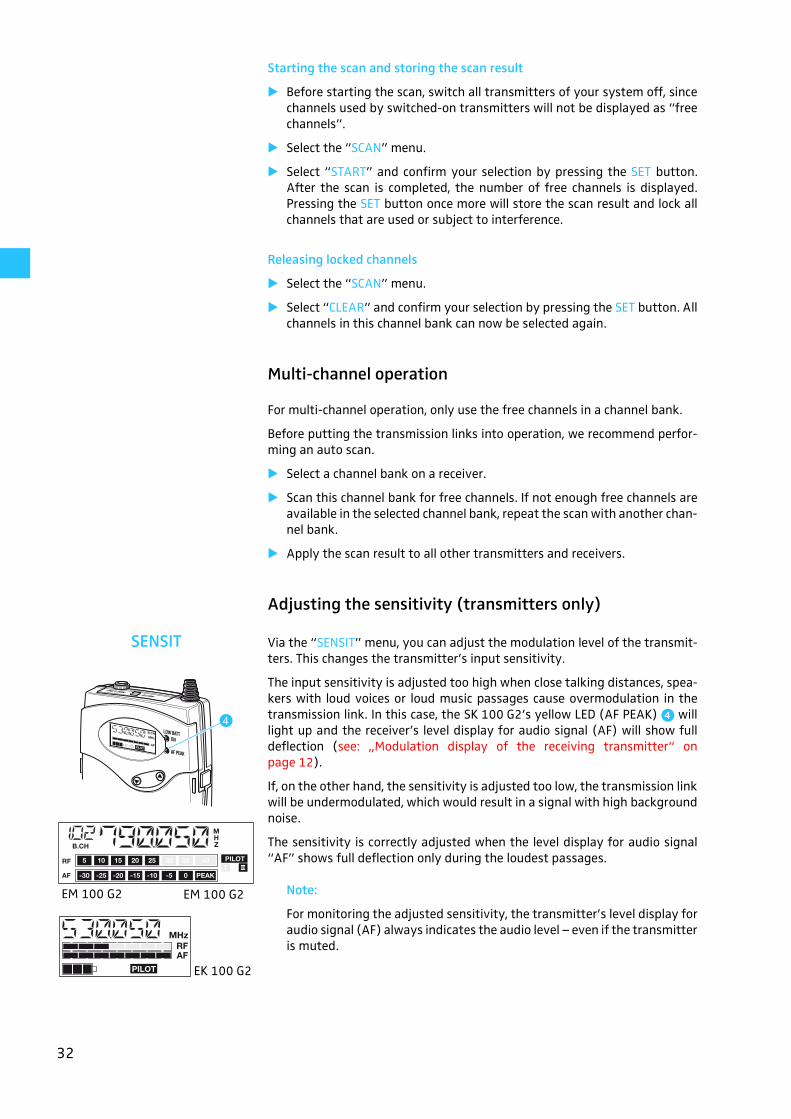
Adjusting the sensitivity (transmitters only)
SENSIT Via the “SENSIT” menu, you can adjust the modulation level of the transmit-ters. This changes the transmitter’s input sensitivity.
The input sensitivity is adjusted too high when close talking distances, spea-kers with loud voices or loud music passages cause overmodulation in thetransmission link. In this case, the SK 100 G2’s yellow LED (AF PEAK) � willlight up and the receiver’s level display for audio signal (AF) will show fulldeflection (see: „Modulation display of the receiving transmitter“ onpage 12).
If, on the other hand, the sensitivity is adjusted too low, the transmission linkwill be undermodulated, which would result in a signal with high backgroundnoise.
The sensitivity is correctly adjusted when the level display for audio signal“AF” shows full deflection only during the loudest passages.
EM 100 G2 Note:
For monitoring the adjusted sensitivity, the transmitter’s level display foraudio signal (AF) always indicates the audio level – even if the transmitteris muted.
�
EM 100 G2
EK 100 G2
33
The following figures are a guide to the best settings:
Loud music/vocals: –30 to –20 dB
Presentations: –20 to –10 dB
Interviews: –10 to 0 dB
Musical instruments:
– electric guitars with single coil pickups: –10 to 0 dB– electric guitars with humbucker pickups: –20 to –10 dB– guitars with active electronics
(active pickups, active EQs, piezo pickups): –30 to –20 dB
Special feature of the SKP 100 G2 plug-on transmitter:
In order to be able to use highly sensitive directional condenser microphoneswith separate powering, the SKP 100 G2 plug-on transmitter offers a sensiti-vity range extended by 20 dB. With the transmitter plugged onto a directio-nal condenser microphone, the following figures are a guide to the best set-tings:
Loud music/vocals: –50 to –40 dB
Presentations: –40 to –30 dB
Interviews: –30 to –20 dB
Adjusting the audio output level (receivers only)
AF OUT Via the “AF OUT” menu, you can adjust the audio output level of the receivers.The level can be adjusted in eight steps. Adapt the level of the audio output(AF OUT) to the input of the connected unit. The following figures are a guideto the best settings:
EM 100 G2 EK 100 G2
Line level input: 0 bis +18 dB 0 bis +12 dB
Microphone level input: –24 bis –6 dB –30 bis –6 dB
Adjusting the squelch threshold (receivers only)
SQELCH The receiver is equipped with a squelch that can be adjusted via the “SQELCH”menu. The squelch eliminates annoying noise when the transmitter isswitched off. It also suppresses sudden noise when there is no longersufficient transmitter power received by the receiver.
Note:
Before adjusting the squelch threshold to a different setting, set thevolume on a connected amplifier to the minimum.
There are three possible squelch settings:
LO = low
MID = middle
HI = high
Selecting the setting “LO” reduces the squelch threshold, selecting the set-ting “HI” increases the squelch threshold. Adjust the squelch threshold – withthe transmitter switched off – to the lowest possible setting that suppresseshissing noise.
34
IMPORTANT! Notes:
If the squelch threshold is adjusted too high, the transmission range willbe reduced. Therefore, always adjust the squelch threshold to the lowestpossible setting. The squelch threshold is factory-preset to “LO”.
When in the setting mode of the “SQELCH” menu, pressing the � button(DOWN) for more than three seconds will switch the squelch off. “SQ.OFF”appears on the display. If no RF signal is being received, hissing noise willoccur. This setting is for test purposes only.
Selecting the standard display
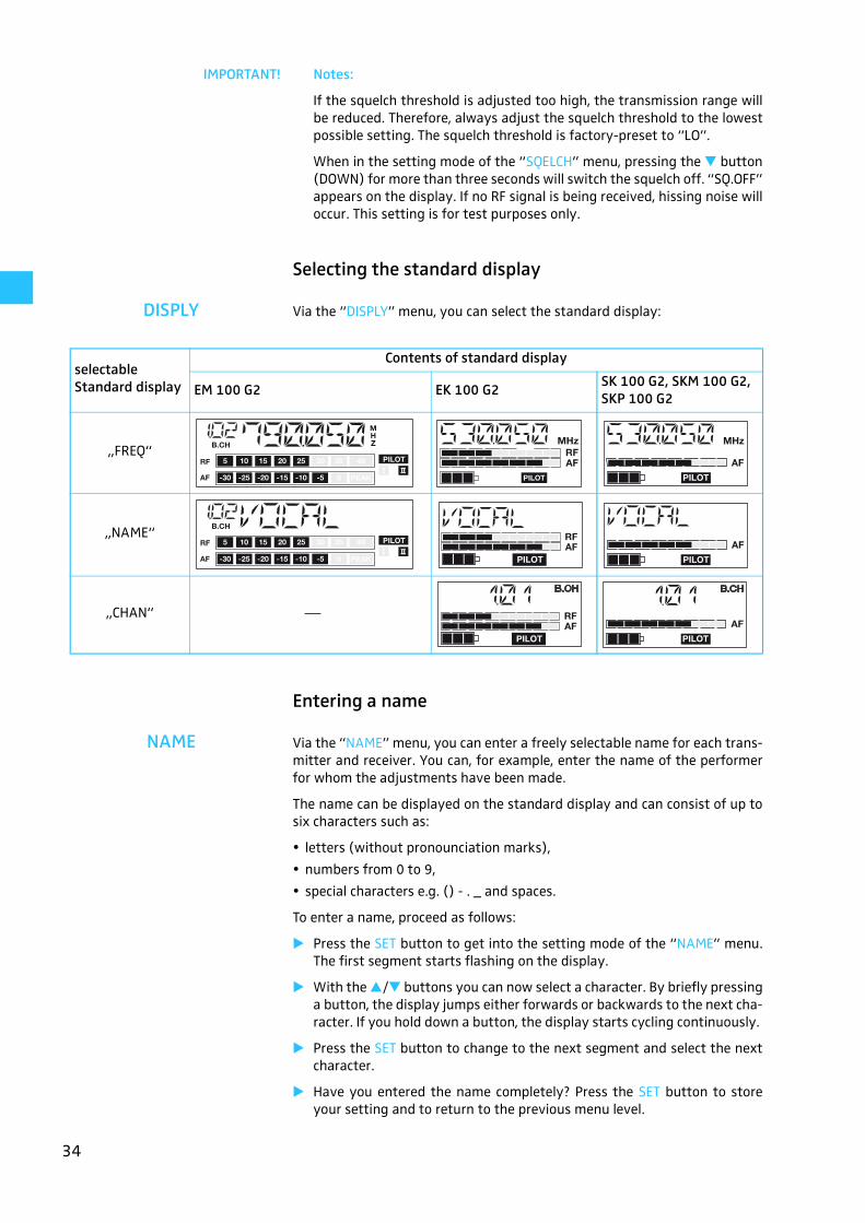
DISPLY Via the “DISPLY” menu, you can select the standard display:
Entering a name
NAME Via the “NAME” menu, you can enter a freely selectable name for each trans-mitter and receiver. You can, for example, enter the name of the performerfor whom the adjustments have been made.
The name can be displayed on the standard display and can consist of up tosix characters such as:
letters (without pronounciation marks),
numbers from 0 to 9,
special characters e.g. () - . _ and spaces.
To enter a name, proceed as follows:
� Press the SET button to get into the setting mode of the “NAME” menu.The first segment starts flashing on the display.
� With the �/� buttons you can now select a character. By briefly pressinga button, the display jumps either forwards or backwards to the next cha-racter. If you hold down a button, the display starts cycling continuously.
� Press the SET button to change to the next segment and select the nextcharacter.
� Have you entered the name completely? Press the SET button to storeyour setting and to return to the previous menu level.
selectable Standard display
Contents of standard display
EM 100 G2 EK 100 G2SK 100 G2, SKM 100 G2, SKP 100 G2
„FREQ“
„NAME“
„CHAN“ ⎯
35
Loading the factory-preset default settings
RESET Via the “RESET” menu, you can load the factory-preset default settings. Onlythe selected setting for the pilot tone remains unchanged. After the reset, theunit is restarted and the standard display is shown on the display panel.
Activating/deactivating the pilot tone transmission or pilot tone evaluation
PILOT Via the “PILOT” menu, you can activate or deactivate the pilot tone transmis-sion of the transmitters and the pilot tone evaluation of the receivers.
The pilot tone supports the squelch function (SQELCH) and protects againstinterference due to RF signals from other units. The transmitter adds an inau-dible signal, known as the pilot tone, to the transmitted signal. The receiverdetects and evaluates the pilot tone, and is thus able to identify the signal ofthe matching transmitter and mute all others.
Transmitters of the ew 100 series (first generation) do not transmit a pilottone and receivers of the ew 100 series (first generation) cannot evaluatethe pilot tone. Nevertheless, you can combine units of the ew 100 series (firstgeneration) with units of the ew 100 G2 series (second generation).
However, when combining units, please observe the following:
With an ew 100 G2 transmitter and an ew 100 G2 receiver:Activate the pilot tone function with both transmitter and receiver.
With an ew 100 transmitter and an ew 100 G2 receiver or vice versa:Deactivate the pilot tone function with the ew 100 G2 transmitter or recei-ver.
Activating/deactivating the lock mode
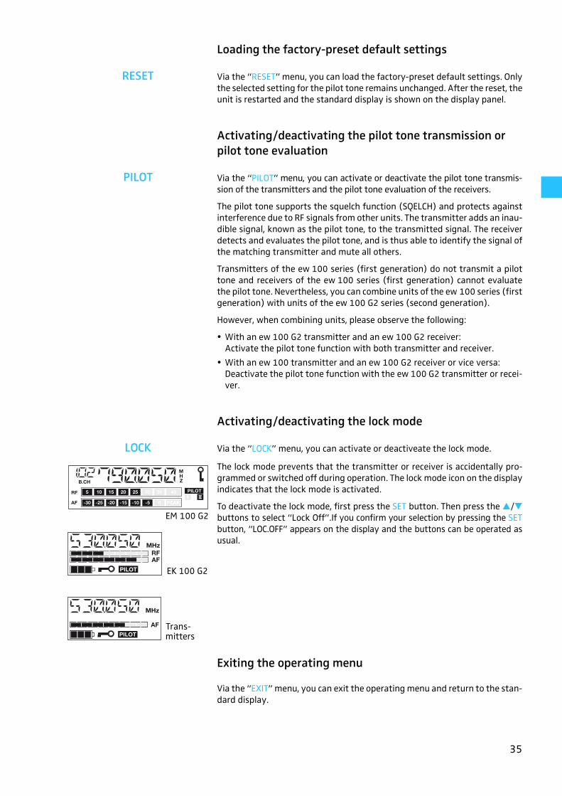
LOCK Via the “LOCK” menu, you can activate or deactiveate the lock mode.
The lock mode prevents that the transmitter or receiver is accidentally pro-grammed or switched off during operation. The lock mode icon on the displayindicates that the lock mode is activated.
To deactivate the lock mode, first press the SET button. Then press the �/�buttons to select “Lock Off”.If you confirm your selection by pressing the SETbutton, “LOC.OFF” appears on the display and the buttons can be operated asusual.
Exiting the operating menu
Via the “EXIT” menu, you can exit the operating menu and return to the stan-dard display.
EM 100 G2
EK 100 G2
Trans-mitters
36
If problems occur
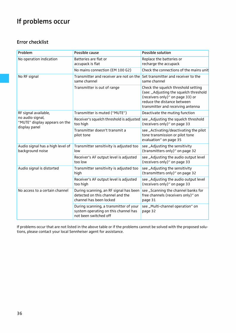
Error checklist
If problems occur that are not listed in the above table or if the problems cannot be solved with the proposed solu-tions, please contact your local Sennheiser agent for assistance.
Problem Possible cause Possible solution
No operation indication Batteries are flat or accupack is flat
Replace the batteries or recharge the accupack
No mains connection (EM 100 G2) Check the connections of the mains unit
No RF signal Transmitter and receiver are not on the same channel
Set transmitter and receiver to the same channel
Transmitter is out of range Check the squelch threshold setting (see: „Adjusting the squelch threshold (receivers only)“ on page 33) or reduce the distance between transmitter and receiving antenna
RF signal available, no audio signal,“MUTE” display appears on the display panel
Transmitter is muted (“MUTE”) Deactivate the muting function
Receiver’s squelch threshold is adjusted too high
see „Adjusting the squelch threshold (receivers only)“ on page 33
Transmitter doesn’t transmit a pilot tone
see „Activating/deactivating the pilot tone transmission or pilot tone evaluation“ on page 35
Audio signal has a high level of background noise
Transmitter sensitivity is adjusted too low
see „Adjusting the sensitivity (transmitters only)“ on page 32
Receiver’s AF output level is adjusted too low
see „Adjusting the audio output level (receivers only)“ on page 33
Audio signal is distorted Transmitter sensitivity is adjusted too high
see „Adjusting the sensitivity (transmitters only)“ on page 32
Receiver’s AF output level is adjusted too high
see „Adjusting the audio output level (receivers only)“ on page 33
No access to a certain channel During scanning, an RF signal has been detected on this channel and the channel has been locked
see „Scanning the channel banks for free channels (receivers only)“ on page 31
During scanning, a transmitter of your system operating on this channel has not been switched off
see „Multi-channel operation“ on page 32

37
Recommendations and tips
... for the ME 2 and ME 4 clip-on microphones
To reduce level variations to a minimum when the user turns his or her headaway from the microphone, attach the microphone as centrally as possible.
To protect the microphone against excessive sweat/moisture, avoid directskin contact.
Attach the microphone carefully and conduct the cable so that noise due tofriction is avoided.
Always use the ME 4 directional microphone with a windshield and directthe microphone towards the sound source (e.g. mouth).
... for the ME 3 headmic
Always use the microphone with a popshield and position the microphoneat the corner of the mouth.
You can vary the bass reproduction by increasing/decreasing the talkingdistance to the microphone.
Make sure that the sound inlet is directed towards the mouth. The soundinlet is marked with a little dot.
... for the SK 100 G2 bodypack transmitter
Make sure that the antenna and the microphone cable do not cross.
The antenna should hang freely and be at least 1 cm away from the body.The antenna must not be in direct contact with the skin.
For best results, make sure that the transmitter sensitivity is correctlyadjusted.
... for the SKM 100 G2 radiomicrophone
Hold the SKM 100 G2 in the middle of the microphone body. Holding it closeto the sound inlet basket will influence the microphone’s pick-up pattern,holding it at the lower part of the body will reduce the transmitter’s range.
You can vary the bass reproduction by increasing/decreasing the talkingdistance to the microphone.
For best results, make sure that the transmitter sensitivity is correctlyadjusted.
... for the EK 100 G2 bodypack receiver
The antenna should hang freely and be at least 1 cm away from the body.The antenna must not be in direct contact with the skin.
... for optimum reception
Transmission range depends to a large extent on location and can varyfrom about 10 m to about 150 m. There should be a “free line of sight” bet-ween transmitting and receiving antennas.
If, with the EM 100 G2 receiver, reception conditions are unfavourable, youshould use two remote antennas which are connected via antenna cable.
To avoid overmodulating the receiver, observe a minimum distance of 5 mbetween transmitting and receiving antennas.
Observe a minimum distance of 50 cm between receiving antennas andmetal objects (such as cross members or reinforced-concrete walls).
38
... for multi-channel operation
For multi-channel operation, you can only use the channels in a channelbank. Each of the channel banks “1” to “8” accommodates four factory-preset frequencies which are intermodulation-free. For alternative fre-quency combinations, please refer to the enclosed frequency table. The fre-ely selectable frequencies can be selected via the “TUNE” menu and can bestored in the channel bank “U”.
When using several transmitters simultaneously, interference can be avoi-ded by maintaining a minimum distance of 20 cm between two transmit-ters.
Use special accessories for multi-channel applications (see: „Accessories“on page 45).
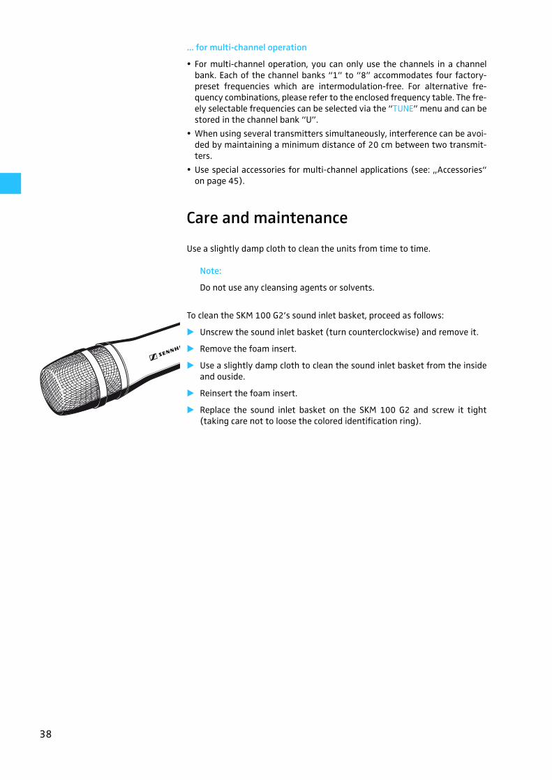
Care and maintenance
Use a slightly damp cloth to clean the units from time to time.
Note:
Do not use any cleansing agents or solvents.
To clean the SKM 100 G2’s sound inlet basket, proceed as follows:
� Unscrew the sound inlet basket (turn counterclockwise) and remove it.
� Remove the foam insert.
� Use a slightly damp cloth to clean the sound inlet basket from the insideand ouside.
� Reinsert the foam insert.
� Replace the sound inlet basket on the SKM 100 G2 and screw it tight(taking care not to loose the colored identification ring).

39
Additional information
HDX noise reduction
Progress you can hear:
The evolution wireless G2 series is equipped with HDX, the Sennheiser noisereduction system that reduces RF interference. It increases the signal-to-noise ratio in wireless audio transmission to more than 110 dB.
HDX is a wideband compander system which compresses the audio signal inthe transmitter in a 2:1 ratio (related to dB) to lift it above the inherent noisefloor of the RF link. A 110 dB dynamic range signal is thus transmitted withan effective dynamic range of only 55 dB, which is above the 60 dB noise floorof the RF link. In the receiver the signal is expanded in an identical and oppo-site way in a 1:2 ratio to restore the original signal, at the same time reducingthe RF noise to below the noise floor of the receiver.
HDX has been specially developed for high quality radiomicrophone systems.
Note:
Only transmitters and receivers that are equipped with HDX can work cor-rectly with each other. If non HDX equipment was mixed with HDX, thedynamic range would be drastically reduced and the transmission wouldsound blunt and flat. HDX is permanently active and cannot be switchedoff.
RF link
Transmitter Receiver
Inherent noise of the RF link

40
Wireless transmission systems
With the ew 100 G2 series, Sennheiser puts an end to cable tangles and enab-les complete freedom of movement. The systems operate exclusively in theUHF band. UHF transmission is extremely reliable and is far less prone tointerference than the overcrowded VHF band – harmonics from mains units,fluorescent tubes, refrigerators, computers, etc. are virtually eliminated. Alsoindoor propagation of UHF radio waves is better than VHF so that the RFpower can be kept low – this is also an advantage when using multi-channelsystems. Finally, UHF frequency ranges are being approved all over the worldfor radiomicrophone usage – in some countries licence-free.
There are three transmitter versions: The hand-held transmitter is a completeradiomicrophone in a single unit, the plug-on transmitter converts yourfavourite wired microphone into a radiomicrophone, the bodypack transmit-ter can accept a wide range of inputs including: omni-directional or cardioidclip-on microphones, head-worn microphone, guitar/instrument direct inputand auxiliary units via the optional CL 2 line input cable.
Correct adjustment of transmitter sensitivity is vital. Too high and you getovermodulation and distortion, too low and you get undermodulation and anoisy signal. Please set the sensitivity correctly for the microphone/usageand check it before every performance to ensure best operation.
Sennheiser miniature clip-on microphones can be attached in various ways:they can, for example, be attached to the hairline or to clothing (e.g. tie orlapel). However it is fixed, please make sure that the microphone is protectedagainst sweat/moisture and make-up.
Squelch
Pilot tone squelch
The transmitter adds a pilot tone to the audio signal. The receiver checksincoming audio signals to see if the pilot tone is present. In the absence of thesignal, the receiver’s audio output will remain muted, even if a strong RF sig-nal is present.
This prevents strong interfering signals from causing hissing noise in thereceiver when the transmitter is switched off.
In order to benefit from this feature, the pilot tone function must be activatedon both the transmitter and the receiver. The pilot tone function is factory-preset to “ON” (= activated).
Field strength-dependent squelch
Depending on the strength of the received RF signal, the receiver’s audio out-put is opened or muted. Via the “SQELCH” menu of the receiver, the squelchthreshold can be adjusted in three steps (LO, MID, HI).
41
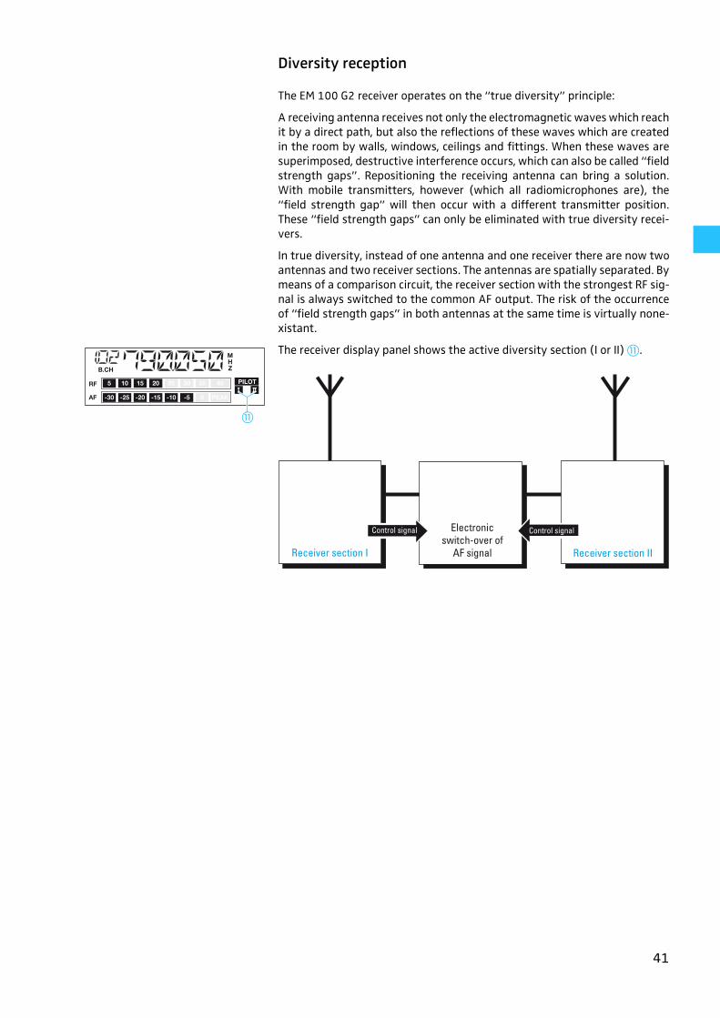
Diversity reception
The EM 100 G2 receiver operates on the “true diversity” principle:
A receiving antenna receives not only the electromagnetic waves which reachit by a direct path, but also the reflections of these waves which are createdin the room by walls, windows, ceilings and fittings. When these waves aresuperimposed, destructive interference occurs, which can also be called “fieldstrength gaps”. Repositioning the receiving antenna can bring a solution.With mobile transmitters, however (which all radiomicrophones are), the“field strength gap” will then occur with a different transmitter position.These “field strength gaps” can only be eliminated with true diversity recei-vers.
In true diversity, instead of one antenna and one receiver there are now twoantennas and two receiver sections. The antennas are spatially separated. Bymeans of a comparison circuit, the receiver section with the strongest RF sig-nal is always switched to the common AF output. The risk of the occurrenceof “field strength gaps” in both antennas at the same time is virtually none-xistant.
The receiver display panel shows the active diversity section (I or II) �.
�
Receiver section I
Electronicswitch-over of
AF signal Receiver section II
Control signalControl signal
42
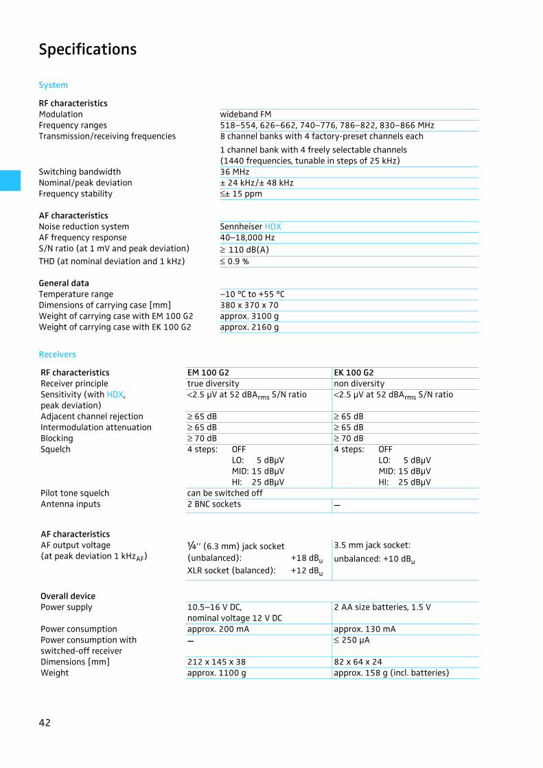
Specifications
System
Receivers
RF characteristicsModulation wideband FMFrequency ranges 518–554, 626–662, 740–776, 786–822, 830–866 MHz Transmission/receiving frequencies 8 channel banks with 4 factory-preset channels each
1 channel bank with 4 freely selectable channels (1440 frequencies, tunable in steps of 25 kHz)
Switching bandwidth 36 MHzNominal/peak deviation ± 24 kHz/± 48 kHzFrequency stability ≤ ± 15 ppm
AF characteristicsNoise reduction system Sennheiser HDXAF frequency response 40–18,000 HzS/N ratio (at 1 mV and peak deviation) ≥ 110 dB(A)THD (at nominal deviation and 1 kHz) ≤ 0.9 %
General dataTemperature range –10 °C to +55 °CDimensions of carrying case [mm] 380 x 370 x 70Weight of carrying case with EM 100 G2 approx. 3100 gWeight of carrying case with EK 100 G2 approx. 2160 g
RF characteristics EM 100 G2 EK 100 G2Receiver principle true diversity non diversitySensitivity (with HDX, peak deviation)
<2.5 μV at 52 dBArms S/N ratio <2.5 μV at 52 dBArms S/N ratio
Adjacent channel rejection ≥ 65 dB ≥ 65 dBIntermodulation attenuation ≥ 65 dB ≥ 65 dBBlocking ≥ 70 dB ≥ 70 dBSquelch 4 steps: OFF
LO: 5 dBμVMID: 15 dBμVHI: 25 dBμV
4 steps: OFF LO: 5 dBμVMID: 15 dBμVHI: 25 dBμV
Pilot tone squelch can be switched offAntenna inputs 2 BNC sockets –
AF characteristicsAF output voltage (at peak deviation 1 kHzAF)
¼’’ (6.3 mm) jack socket (unbalanced): +18 dBuXLR socket (balanced): +12 dBu
3.5 mm jack socket:
unbalanced: +10 dBu
Overall devicePower supply 10.5–16 V DC,
nominal voltage 12 V DC2 AA size batteries, 1.5 V
Power consumption approx. 200 mA approx. 130 mAPower consumption with switched-off receiver
– ≤ 250 μA
Dimensions [mm] 212 x 145 x 38 82 x 64 x 24Weight approx. 1100 g approx. 158 g (incl. batteries)

43
Transmitters
Microphones
Connector assignment
RF characteristics SK 100 G2 SKP 100 G2 SKM 100 G2RF output power at 50 Ω typ. 30 mW
AF characteristicsMax. input voltage (at peak deviation)
Microphone 1.8 Vrms, unbalanced 1.2 Veff, unbalanced –Line 2.4 Vrms – –
Input impedanceMicrophone 10 kΩ, unbalanced 10 kΩ, unbalanced –
Line 1 MΩ – –
Overall devicePower supply 2 AA size batteries, 1.5 VNominal voltage 2.4 V 2.4 V 2.4 VMax. power consumption at nominal voltage ≤ 170 mAPower consumption with switched-off transmitter
≤ 250 μA ≤ 250 μA ≤ 250 μA
Operating time (with batteries) > 8 h > 8 h > 8 hOperating time (with BA 2015 accupack) > 8 h > 8 h > 8 hDimensions [mm] 82 x 64 x 24 105 x 43 x 43 ∅ 50 x 225Weight (incl. batteries) approx. 158 g approx. 195 g approx. 450g
ME 2 ME 3 ME 4Transducer principle condenser condenser condenserSensitivity 20 mV/Pa 1.6 mV/Pa 40 mV/PaPick-up pattern omni-driectional super-cardioid cardioidMax. SPL 130 dB SPL 150 dB SPL 120 dB SPL
Microphone headsMD 835 MD 845 ME 865
Transducer principle dynamic dynamic condenserSensitivity 1.5 mV/Pa 1 mV/Pa 3 mV/PaPick-up pattern cardioid super-cardioid super-cardioidMax. SPL 150 dB SPL 154 dB SPL 144 dB SPLColor of identification ring green blue red
EM 100 G2:
¼’’ (6.3 mm) stereo jackplug, unbalanced
EM 100 G2:
¼’’ (6.3 mm) mono jackplug, unbalanced
EM 100 G2:
XLR-3F connector, balanced
EM 100 G2:
DC connector for power supply
SK 100 G2:
3.5 mm jack plug
EK 100 G2:
3.5 mm stereo jack plug, unbalanced
EK 100 G2:
3.5 mm mono jack plug, unbalanced
NC/GN D
2 1
3
+
EW_100_US.fm Seite 43 Freitag, 8. Dezember 2006 10:35 10
44
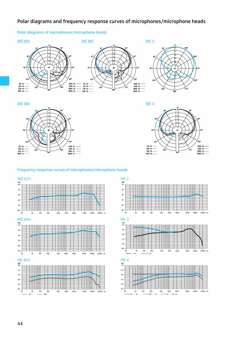
Polar diagrams and frequency response curves of microphones/microphone heads
Polar diagrams of microphones/microphone heads
Frequency response curves of microphones/microphone heads
MD 835 ME 865 ME 3
MD 845 ME 4
MD 835 ME 2
MD 845 ME 3
ME 865 ME 4
45
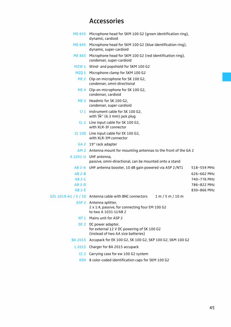
Accessories
MD 835 Microphone head for SKM 100 G2 (green identification ring),dynamic, cardioid
MD 845 Microphone head for SKM 100 G2 (blue identification ring),dynamic, super-cardioid
ME 865 Microphone head for SKM 100 G2 (red identification ring),condenser, super-cardioid
MZW 1 Wind- and popshield for SKM 100 G2
MZQ 1 Microphone clamp for SKM 100 G2
ME 2 Clip-on microphone for SK 100 G2,condenser, omni-directional
ME 4 Clip-on microphone for SK 100 G2,condenser, cardioid
ME 3 Headmic for SK 100 G2,condenser, super-cardioid
CI 1 Instrument cable for SK 100 G2,with ¼” (6.3 mm) jack plug
CL 2 Line input cable for SK 100 G2,with XLR-3F connector
CL 100 Line input cable for EK 100 G2,with XLR-3M connector
GA 2 19” rack adapter
AM 2 Antenna mount for mounting antennas to the front of the GA 2
A 1031-U UHF antenna,passive, omni-directional, can be mounted onto a stand
AB 2-A UHF antenna booster, 10 dB gain powered via ASP 2/NT1 518–554 MHz
AB 2-B 626–662 MHzAB 2-C 740–776 MHzAB 2-D 786–822 MHzAB 2-E 830–866 MHz
GZL 1019-A1 / 5 / 10 Antenna cable with BNC connectors 1 m / 5 m / 10 m
ASP 2 Antenna splitter,2 x 1:4, passive, for connecting four EM 100 G2 to two A 1031-U/AB 2
NT 1 Mains unit for ASP 2
DC 2 DC power adapter,for external 12 V DC powering of SK 100 G2(instead of two AA size batteries)
BA 2015 Accupack for EK 100 G2, SK 100 G2, SKP 100 G2, SKM 100 G2
L 2015 Charger for BA 2015 accupack
CC 2 Carrying case for ew 100 G2 system
KEN 8 color-coded identification caps for SKM 100 G2
46
Manufacturer declarations
Warranty regulations
The guarantee period for this Sennheiser product is 24 months from the date ofpurchase. Excluded are accessory items, rechargeable or disposable batteries that aredelivered with the product; due to their characteristics these products have a shorterservice life that is principally dependent on the individual frequency of use.
The guarantee period starts from the date of original purchase. For this reason, werecommend that the sales receipt be retained as proof of purchase. Without this proof(which is checked by the responsible Sennheiser service partner) you will not be reim-bursed for any repairs that are carried out.
Depending on our choice, guarantee service comprises, free of charge, the removal ofmaterial and manufacturing defects through repair or replacement of either indivi-dual parts or the entire device. Inappropriate usage (e.g. operating faults, mechanicaldamages, incorrect operating voltage), wear and tear, force majeure and defectswhich were known at the time of purchase are excluded from guarantee claims. Theguarantee is void if the product is manipulated by non-authorised persons or repairstations.
In the case of a claim under the terms of this guarantee, send the device, includingacces-sories and sales receipt, to the responsible service partner. To minimise the riskof transport damage, we recommend that the original packaging is used. Your legalrights against the seller, resulting from the contract of sale, are not affected by thisguarantee.
The guarantee can be claimed in all countries outside the U.S. provided that no natio-nal law limits our terms of guarantee.
CE Declaration of Conformity
This equipment is in compliance with the essential requirements and other relevantprovisions of Directives 1999/5/EC, 89/336/EC or 73/23/EC. The declaration is avai-lable on the internet site at www.sennheiser.com.
Before putting the device into operation, please observe the respective country-spe-cific regulations!
Batteries or rechargeable batteries
The supplied batteries or rechargeable batteries can be recycled. Pleasedispose of them as special waste or return them to your specialist dealer. Inorder to protect the environment, only dispose of exhausted batteries.
WEEE Declaration
Your Sennheiser product was developed and manufactured with highqualitymaterials and components which can be recycled and/or reused. This symbolindicates that electrical and electronic equipment must be disposed of sepa-rately from normal waste at the end of its operational lifetime.
Please dispose of this product by bringing it to your local collection point or recyclingcentre for such equipment. This will help to protect the environment in which we alllive.

Sennheiser electronic GmbH & Co. KG30900 Wedemark, GermanyPhone +49 (5130) 600 0Fax +49 (5130) 600 300www.sennheiser.com
Printed in Germany Publ. 01/07 090608/A3