Embed Size (px)
Citation preview
1
EN - english
Instructions for installation and operation
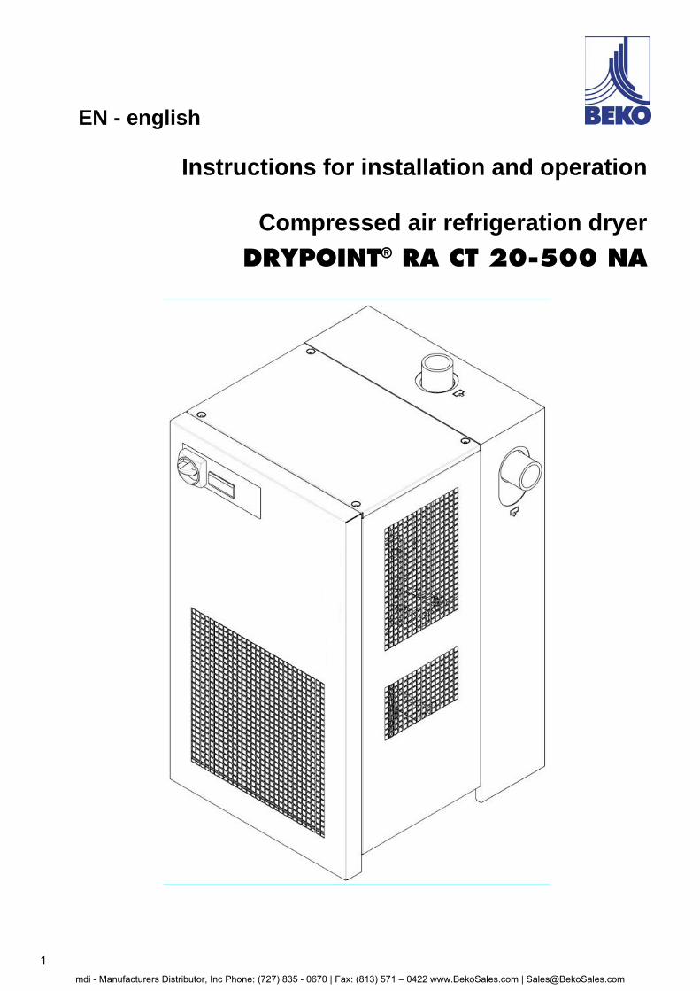
Compressed air refrigeration dryer
DRYPOINT® RA CT 20-500 NA
mdi - Manufacturers Distributor, Inc Phone: (727) 835 - 0670 | Fax: (813) 571 – 0422 www.BekoSales.com | [email protected]
2 DRYPOINT® RA CT 20-500 NA
Dear customer, Thank you for deciding in favour of the DRYPOINT® RA CT 20-500 NA compressed-air refrigeration dryer. Please read these installation and operating instructions carefully before mounting and starting up the DRYPOINT® RA CT 20-500 NA and follow our directions. Perfect functioning of the DRYPOINT® RA CT 20-500 NA and thus reliable compressed-air drying can only be guaranteed when the provisions and notes stipulated here are strictly adhered to.
mdi - Manufacturers Distributor, Inc Phone: (727) 835 - 0670 | Fax: (813) 571 – 0422 www.BekoSales.com | [email protected]
DRYPOINT® RA CT 20-500 NA 3
Contents
1 Type plate 5
2 Safety instructions 5 2.1 Safety pictograms in accordance with DIN 4844 6 2.2 Signal words in accordance with ANSI 8 2.3 Overview of the safety instructions 8
3 Proper use 11
4 Exclusion from a field of application 11
5 Operating instructions in accordance with the 97/23/EC Pressure Equipment Directive 11
6 Transport 12
7 Storage 12
8 Technical description 13 8.1 Control panel 13 8.2 Functional description 14 8.3 Flow chart 15 8.4 Refrigerating compressor 16 8.5 Condenser 16 8.6 Filter dryer 16 8.7 Capillary tube 16 8.8 Aluminium heat exchanger 16 8.9 Hot-gas bypass valve 17 8.10 Refrigerant pressure switches LPS – HPS – PV 17 8.11 Compressor crankcase heater (RA CT 200-500 NA 3phase) 17 8.12 DMC 51 electronics (control unit compressed-air dryer) 18 8.12.1 Switching the dryer on 18 8.12.2 Switching the dryer off 18 8.12.3 Indication of the operating parameters 18 8.12.4 Indication of a Service Warning 19 8.12.5 Indication of an Alarm 19 8.12.6 Operation of the Service Warning / Alarm signal 20 8.12.7 How to change operating parameters – SETUP menu 20 8.13 Electronically level-controlled BEKOMAT condensate drain 20
9 Installation 21 9.1 Place of installation 21 9.2 Installation plan 22 9.3 Correction factors 23 9.4 Connection to the compressed-air system 24 9.5 Electrical connections 25 9.6 Condensate drain 25
10 Start-up 26 10.1 Preliminary stages 26 10.2 Initial start-up 26 10.3 Shut down and restart 27
11 Technical data 28 11.1 Technical data DRYPOINT RA CT 20-200 NA 1/115/60 28 11.2 Technical data DRYPOINT RA CT 20-500 NA 1/230/60 29 11.3 Technical data DRYPOINT RA CT 200-500 NA 3phase 3/460/50 30 11.4 Technical data DRYPOINT RACT 200-500 NA 3phase 3/380/60 31
12 Maintenance, troubleshooting, spare parts and dismantling 32 12.1 Checks and maintenance 32 12.2 Troubleshooting 33 12.3 Recommended spare parts 38 12.4 Maintenance works at the refrigeration cycle 41 12.5 Dismantling the dryer 41
13 Appendices 42 13.1 Dryer dimensions 42 13.1.1 Dryer dimensions DRYPOINT RA CT 20-50 NA 42 13.1.2 Dryer dimensions DRYPOINT RA CT 75 NA 43
mdi - Manufacturers Distributor, Inc Phone: (727) 835 - 0670 | Fax: (813) 571 – 0422 www.BekoSales.com | [email protected]
4 DRYPOINT® RA CT 20-500 NA
13.1.3 Dryer dimensions DRYPOINT RA CT 100-150 NA 44 13.1.4 Dryer dimensions DRYPOINT RA CT 200-250 NA 45 13.1.5 Dryer dimensions DRYPOINT RA CT 300-350 NA 46 13.1.6 Dryer dimensions DRYPOINT RA CT 400-500 NA 47 13.1.7 Dryer dimensions DRYPOINT RA CT 200-250 NA 3phase 48 13.1.8 Dryer dimensions DRYPOINT RA CT 300-350 NA 3phase 49 13.1.9 Dryer dimensions DRYPOINT RA CT 400-500 NA 3phase 50 13.2 Exploded diagrams 51 13.2.1 Components of the exploded diagrams 51 13.2.2 Exploded diagram DRYPOINT RA CT 20-30 NA 52 13.2.3 Exploded diagram DRYPOINT RA CT 50 NA 53 13.2.4 Exploded diagram DRYPOINT RA CT 75 NA 54 13.2.5 Exploded diagram DRYPOINT RA CT 100 NA 55 13.2.6 Exploded diagram DRYPOINT RA CT 125-150 NA 56 13.2.7 Exploded diagram DRYPOINT RA CT 200-250 NA 57 13.2.8 Exploded diagram DRYPOINT RA CT 300-350 NA 58 13.2.9 Exploded diagram DRYPOINT RA CT 400-500 NA 59 13.2.10 Exploded diagram DRYPOINT RA CT 200-250 NA 3phase 60 13.2.11 Exploded diagram DRYPOINT RA CT 300-350 NA 3phase 61 13.2.12 Exploded diagram DRYPOINT RA CT 400-500 NA 3phase 62 13.3 Electric diagrams 63 13.3.1 Electric diagrams – list of components 63 13.3.2 Electric diagram DRYPOINT RA CT 20-100 NA 64 13.3.3 Electric diagram DRYPOINT RA CT 125-150 NA 65 13.3.4 Electric diagram DRYPOINT RA CT 200-250 NA 66 13.3.5 Electric diagram DRYPOINT RA CT 300-350 NA 67 13.3.6 Electric diagram DRYPOINT RA CT 400-500 NA 68 13.3.7 Electric diagram DRYPOINT RA CT 200-500 NA 3phase 1/3 69 13.3.8 Electric diagram DRYPOINT RA CT 200-500 NA 3phase 2/3 70 13.3.9 Electric diagram DRYPOINT RA CT 200-500 NA 3phase 3/3 71 Pos: 1 /Beko Technische Dokumentation/Überschriften/1/Sicherheitshinweise @ 0\mod_1183637609261_6.doc @ 5365
mdi - Manufacturers Distributor, Inc Phone: (727) 835 - 0670 | Fax: (813) 571 – 0422 www.BekoSales.com | [email protected]
Type plate
DRYPOINT® RA CT 20-500 NA 5
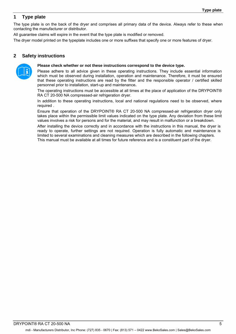
1 Type plate
The type plate is on the back of the dryer and comprises all primary data of the device. Always refer to these when contacting the manufacturer or distributor. All guarantee claims will expire in the event that the type plate is modified or removed. The dryer model printed on the typeplate includes one or more suffixes that specify one or more features of dryer.
2 Safety instructions Pos: 2 /Beko Technische Dokumentation/Globale Texte/Allgemeiner Hinweis BM @ 0\mod_1183615737313_6.doc @ 4004 Pos: 3 /Beko Technische Dokumentation/Sicherheit/Hinweis Anleitung BEKO @ 0\mod_1184147787557_6.doc @ 5758
Please check whether or not these instructions correspond to the device type.
Please adhere to all advice given in these operating instructions. They include essential information which must be observed during installation, operation and maintenance. Therefore, it must be ensured that these operating instructions are read by the fitter and the responsible operator / certified skilled personnel prior to installation, start-up and maintenance.
The operating instructions must be accessible at all times at the place of application of the DRYPOINT® RA CT 20-500 NA compressed-air refrigeration dryer. In addition to these operating instructions, local and national regulations need to be observed, where required . Ensure that operation of the DRYPOINT® RA CT 20-500 NA compressed-air refrigeration dryer only takes place within the permissible limit values indicated on the type plate. Any deviation from these limit values involves a risk for persons and for the material, and may result in malfunction or a breakdown. After installing the device correctly and in accordance with the instructions in this manual, the dryer is ready to operate, further settings are not required. Operation is fully automatic and maintenance is limited to several examinations and cleaning measures which are described in the following chapters. This manual must be available at all times for future reference and is a constituent part of the dryer.
mdi - Manufacturers Distributor, Inc Phone: (727) 835 - 0670 | Fax: (813) 571 – 0422 www.BekoSales.com | [email protected]
Safety instructions
6 DRYPOINT® RA CT 20-500 NA
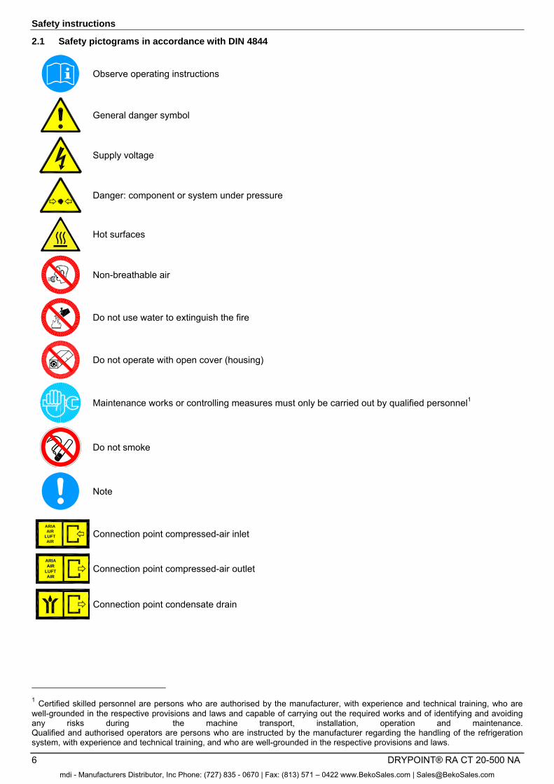
2.1 Safety pictograms in accordance with DIN 4844
Observe operating instructions
General danger symbol
Supply voltage
Danger: component or system under pressure
Hot surfaces
Non-breathable air
Do not use water to extinguish the fire
Do not operate with open cover (housing)
Maintenance works or controlling measures must only be carried out by qualified personnel1
Do not smoke
Note
Pos: 4 /Beko Technische Dokumentation/Sicherheit/Gefahr Druckluft @ 0\mod_1184148143854_6.doc @ 577 6
ARIAAIR
LUFTAIR
Connection point compressed-air inlet
ARIAAIR
LUFTAIR
Connection point compressed-air outlet
Connection point condensate drain
1 Certified skilled personnel are persons who are authorised by the manufacturer, with experience and technical training, who are well-grounded in the respective provisions and laws and capable of carrying out the required works and of identifying and avoiding any risks during the machine transport, installation, operation and maintenance. Qualified and authorised operators are persons who are instructed by the manufacturer regarding the handling of the refrigeration system, with experience and technical training, and who are well-grounded in the respective provisions and laws.
mdi - Manufacturers Distributor, Inc Phone: (727) 835 - 0670 | Fax: (813) 571 – 0422 www.BekoSales.com | [email protected]
Safety instructions
DRYPOINT® RA CT 20-500 NA 7
Works can be carried out by the operator of the plant, provided that they are skilled accordingly2.
NOTE: Text that contains important specifications to be considered – does not refer to safety precautions.
The device was carefully designed with particular attention paid to environmental protection: CFC-free refrigerants CFC-free insulation material Energy-saving design Limited acoustic emissions Dryer and packaging comprise reusable materials This symbol advises the user to observe the environmental aspects and comply with the recommendations connected with this symbol.
2 Certified skilled personnel are persons who are authorised by the manufacturer, with experience and technical training, who are well-grounded in the respective provisions and laws and capable of carrying out the required works and of identifying and avoiding any risks during the machine transport, installation, operation and maintenance. Qualified and authorised operators are persons who are instructed by the manufacturer regarding the handling of the refrigeration system, with experience and technical training, and who are well-grounded in the respective provisions and laws.
mdi - Manufacturers Distributor, Inc Phone: (727) 835 - 0670 | Fax: (813) 571 – 0422 www.BekoSales.com | [email protected]
Safety instructions
8 DRYPOINT® RA CT 20-500 NA
2.2 Signal words in accordance with ANSI
Danger! Imminent hazard Consequences of non-observance: serious injury or death
Warning! Potential hazard Consequences of non-observance: possible serious injury or death
Caution! Imminent hazard Consequences of non-observance: possible injury or property damage
Notice! Potential hazard Consequences of non-observance: possible injury or property damage
Important! Additional advice, info, hints Consequences of non-observance: disadvantages during operation and maintenance, no danger
2.3 Overview of the safety instructions
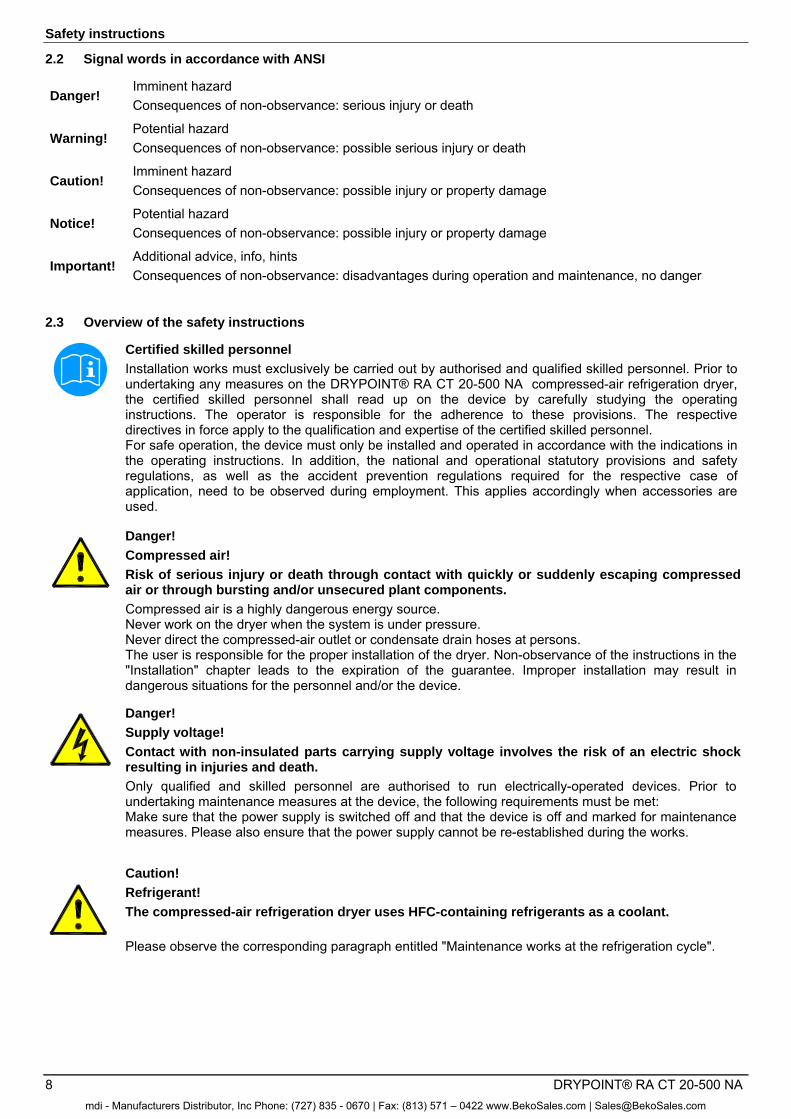
Certified skilled personnel
Installation works must exclusively be carried out by authorised and qualified skilled personnel. Prior to undertaking any measures on the DRYPOINT® RA CT 20-500 NA compressed-air refrigeration dryer, the certified skilled personnel shall read up on the device by carefully studying the operating instructions. The operator is responsible for the adherence to these provisions. The respective directives in force apply to the qualification and expertise of the certified skilled personnel. For safe operation, the device must only be installed and operated in accordance with the indications in the operating instructions. In addition, the national and operational statutory provisions and safety regulations, as well as the accident prevention regulations required for the respective case of application, need to be observed during employment. This applies accordingly when accessories are used.
Danger!
Compressed air!
Risk of serious injury or death through contact with quickly or suddenly escaping compressed air or through bursting and/or unsecured plant components.
Compressed air is a highly dangerous energy source. Never work on the dryer when the system is under pressure. Never direct the compressed-air outlet or condensate drain hoses at persons. The user is responsible for the proper installation of the dryer. Non-observance of the instructions in the "Installation" chapter leads to the expiration of the guarantee. Improper installation may result in dangerous situations for the personnel and/or the device.
Pos: 5 /Beko Technische Dokumentation/Sicherheit/Maßnahmen Druckluft BM @ 0\mod_1184148284291_6.doc @ 5812 Pos: 6 /Beko Technische Dokumentation/Sicherheit/Gefahr Netzspannung @ 0\mod_1184148186948_6.doc @ 5794
Danger!
Supply voltage!
Contact with non-insulated parts carrying supply voltage involves the risk of an electric shock resulting in injuries and death.
Only qualified and skilled personnel are authorised to run electrically-operated devices. Prior to undertaking maintenance measures at the device, the following requirements must be met: Make sure that the power supply is switched off and that the device is off and marked for maintenance measures. Please also ensure that the power supply cannot be re-established during the works.
Pos: 7 /Beko Technische Dokumentation/Sicherheit/Maßnahmen Netzspannung BM 31/32/33 @ 0\mod_1216898430699_6.doc @ 11319
Caution!
Refrigerant!
The compressed-air refrigeration dryer uses HFC-containing refrigerants as a coolant.
Please observe the corresponding paragraph entitled "Maintenance works at the refrigeration cycle".
mdi - Manufacturers Distributor, Inc Phone: (727) 835 - 0670 | Fax: (813) 571 – 0422 www.BekoSales.com | [email protected]
Safety instructions
DRYPOINT® RA CT 20-500 NA 9
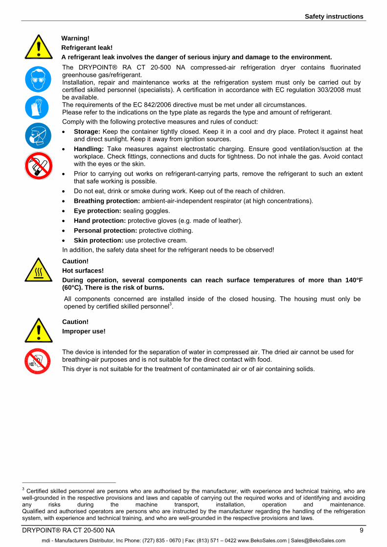
Warning!
Refrigerant leak!
A refrigerant leak involves the danger of serious injury and damage to the environment.
The DRYPOINT® RA CT 20-500 NA compressed-air refrigeration dryer contains fluorinated greenhouse gas/refrigerant. Installation, repair and maintenance works at the refrigeration system must only be carried out by certified skilled personnel (specialists). A certification in accordance with EC regulation 303/2008 must be available. The requirements of the EC 842/2006 directive must be met under all circumstances. Please refer to the indications on the type plate as regards the type and amount of refrigerant. Comply with the following protective measures and rules of conduct: Storage: Keep the container tightly closed. Keep it in a cool and dry place. Protect it against heat
and direct sunlight. Keep it away from ignition sources. Handling: Take measures against electrostatic charging. Ensure good ventilation/suction at the
workplace. Check fittings, connections and ducts for tightness. Do not inhale the gas. Avoid contact with the eyes or the skin.
Prior to carrying out works on refrigerant-carrying parts, remove the refrigerant to such an extent that safe working is possible.
Do not eat, drink or smoke during work. Keep out of the reach of children. Breathing protection: ambient-air-independent respirator (at high concentrations). Eye protection: sealing goggles. Hand protection: protective gloves (e.g. made of leather). Personal protection: protective clothing. Skin protection: use protective cream. In addition, the safety data sheet for the refrigerant needs to be observed!
Caution!
Hot surfaces!
During operation, several components can reach surface temperatures of more than 140°F (60°C). There is the risk of burns.
All components concerned are installed inside of the closed housing. The housing must only be opened by certified skilled personnel3.
Caution!
Improper use!
The device is intended for the separation of water in compressed air. The dried air cannot be used for breathing-air purposes and is not suitable for the direct contact with food. This dryer is not suitable for the treatment of contaminated air or of air containing solids.
3 Certified skilled personnel are persons who are authorised by the manufacturer, with experience and technical training, who are well-grounded in the respective provisions and laws and capable of carrying out the required works and of identifying and avoiding any risks during the machine transport, installation, operation and maintenance. Qualified and authorised operators are persons who are instructed by the manufacturer regarding the handling of the refrigeration system, with experience and technical training, and who are well-grounded in the respective provisions and laws.
mdi - Manufacturers Distributor, Inc Phone: (727) 835 - 0670 | Fax: (813) 571 – 0422 www.BekoSales.com | [email protected]
Safety instructions
10 DRYPOINT® RA CT 20-500 NA
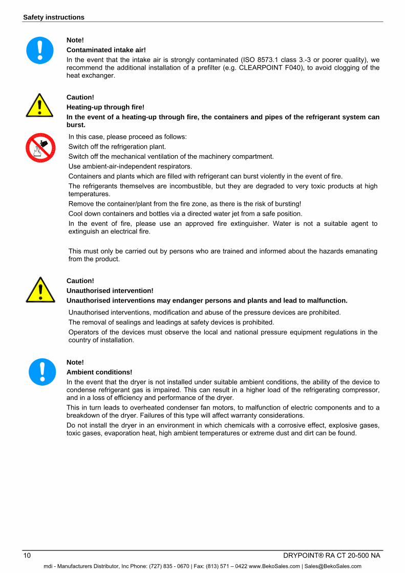
Note!
Contaminated intake air!
In the event that the intake air is strongly contaminated (ISO 8573.1 class 3.-3 or poorer quality), we recommend the additional installation of a prefilter (e.g. CLEARPOINT F040), to avoid clogging of the heat exchanger.
Caution!
Heating-up through fire!
In the event of a heating-up through fire, the containers and pipes of the refrigerant system can burst.
In this case, please proceed as follows: Switch off the refrigeration plant. Switch off the mechanical ventilation of the machinery compartment. Use ambient-air-independent respirators. Containers and plants which are filled with refrigerant can burst violently in the event of fire. The refrigerants themselves are incombustible, but they are degraded to very toxic products at high temperatures. Remove the container/plant from the fire zone, as there is the risk of bursting! Cool down containers and bottles via a directed water jet from a safe position. In the event of fire, please use an approved fire extinguisher. Water is not a suitable agent to extinguish an electrical fire. This must only be carried out by persons who are trained and informed about the hazards emanating from the product.
Caution!
Unauthorised intervention!
Unauthorised interventions may endanger persons and plants and lead to malfunction.
Unauthorised interventions, modification and abuse of the pressure devices are prohibited. The removal of sealings and leadings at safety devices is prohibited. Operators of the devices must observe the local and national pressure equipment regulations in the country of installation.
Pos: 8 /Beko Technische Dokumentation/Sicherheit/Sicherheitshinweise, weitere BM (nicht Ex) @ 0\mod_1183616103770_6.doc @ 4009os: 9 /Beko Technische Dokumentation/Sicherheit/Zusatz Sicherheitshinweise BM33 @ 0\mod_1231926887620_6.doc @ 12829s: 10 /Beko Technische Dokumentation/Sicherheit/Vorsicht Fehlfunktion @ 0\mod_1214378096290_6.doc @ 9359
Note!
Ambient conditions!
In the event that the dryer is not installed under suitable ambient conditions, the ability of the device to condense refrigerant gas is impaired. This can result in a higher load of the refrigerating compressor, and in a loss of efficiency and performance of the dryer. This in turn leads to overheated condenser fan motors, to malfunction of electric components and to a breakdown of the dryer. Failures of this type will affect warranty considerations. Do not install the dryer in an environment in which chemicals with a corrosive effect, explosive gases, toxic gases, evaporation heat, high ambient temperatures or extreme dust and dirt can be found.
Pos: 12 /Beko Technische Dokumentation/Überschriften/1/Bestimmungsgemäße Verwendung @ 0\mod_1183637706293_6.doc @ 5383
mdi - Manufacturers Distributor, Inc Phone: (727) 835 - 0670 | Fax: (813) 571 – 0422 www.BekoSales.com | [email protected]
Proper use
DRYPOINT® RA CT 20-500 NA 11
3 Proper use
This dryer was designed, manufactured and tested to separate the moisture which normally exists in compressed air. Any other use is considered improper. The manufacturer shall not be liable for problems occurring as a consequence of improper use. The user alone is responsible for any damage resulting from that. Furthermore, the correct use includes the compliance with the installation instructions, in particular in respect of: • The voltage and frequency of the main voltage supply. • The pressure, temperature and flow rate of the inlet air. • The ambient temperature. When delivered, the dryer is tested and fully assembled. The customer only needs to connect the device to the system in accordance with the instructions in the following chapters. Pos: 15 /Beko Technische Dokumentation/Übeschriften/1/Ausschluss vom Anwendungsbereich @ 0\mod_1236003439359_6.doc @ 13709
4 Exclusion from a field of application
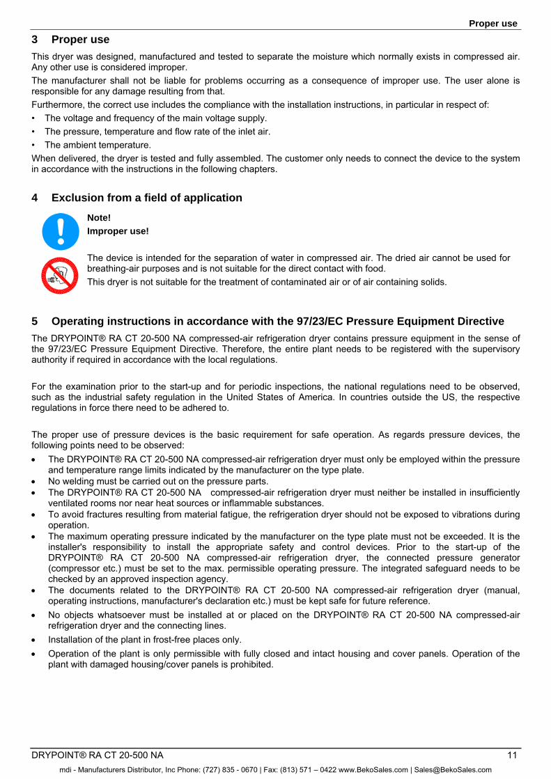
Note!
Improper use! The device is intended for the separation of water in compressed air. The dried air cannot be used for breathing-air purposes and is not suitable for the direct contact with food. This dryer is not suitable for the treatment of contaminated air or of air containing solids.
Pos: 16 /Beko Technische Dokumentation/Bestimmungsgemäße Verwendung/BEKOMAT/Ausschluß Anwendung BM 31/32/33 @ 0\mod_1236003837511_6.doc @ 13736
5 Operating instructions in accordance with the 97/23/EC Pressure Equipment Directive
The DRYPOINT® RA CT 20-500 NA compressed-air refrigeration dryer contains pressure equipment in the sense of the 97/23/EC Pressure Equipment Directive. Therefore, the entire plant needs to be registered with the supervisory authority if required in accordance with the local regulations. For the examination prior to the start-up and for periodic inspections, the national regulations need to be observed, such as the industrial safety regulation in the United States of America. In countries outside the US, the respective regulations in force there need to be adhered to. The proper use of pressure devices is the basic requirement for safe operation. As regards pressure devices, the following points need to be observed: The DRYPOINT® RA CT 20-500 NA compressed-air refrigeration dryer must only be employed within the pressure
and temperature range limits indicated by the manufacturer on the type plate. No welding must be carried out on the pressure parts. The DRYPOINT® RA CT 20-500 NA compressed-air refrigeration dryer must neither be installed in insufficiently
ventilated rooms nor near heat sources or inflammable substances. To avoid fractures resulting from material fatigue, the refrigeration dryer should not be exposed to vibrations during
operation. The maximum operating pressure indicated by the manufacturer on the type plate must not be exceeded. It is the
installer's responsibility to install the appropriate safety and control devices. Prior to the start-up of the DRYPOINT® RA CT 20-500 NA compressed-air refrigeration dryer, the connected pressure generator (compressor etc.) must be set to the max. permissible operating pressure. The integrated safeguard needs to be checked by an approved inspection agency.
The documents related to the DRYPOINT® RA CT 20-500 NA compressed-air refrigeration dryer (manual, operating instructions, manufacturer's declaration etc.) must be kept safe for future reference.
No objects whatsoever must be installed at or placed on the DRYPOINT® RA CT 20-500 NA compressed-air refrigeration dryer and the connecting lines.
Installation of the plant in frost-free places only. Operation of the plant is only permissible with fully closed and intact housing and cover panels. Operation of the
plant with damaged housing/cover panels is prohibited.
mdi - Manufacturers Distributor, Inc Phone: (727) 835 - 0670 | Fax: (813) 571 – 0422 www.BekoSales.com | [email protected]
Transport
12 DRYPOINT® RA CT 20-500 NA
6 Transport
Check the packaging for visible loss or damage. If no visible damage can be ascertained, place the unit in close proximity to the place of installation and unpack the device. During this procedure, the dryer must always remain in an upright position. The components may be damaged when the unit is tilted or turned upside down. Store the device in a dry environment and do not expose it to extreme weather conditions. Handle with care. Strong shocks can cause irreparable damage. 7 Storage
SC
C00
01
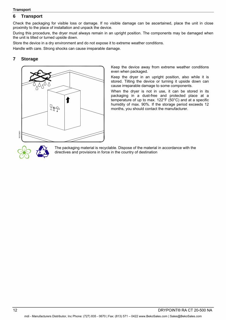
Keep the device away from extreme weather conditions even when packaged. Keep the dryer in an upright position, also while it is stored. Tilting the device or turning it upside down can cause irreparable damage to some components. When the dryer is not in use, it can be stored in its packaging in a dust-free and protected place at a temperature of up to max. 122°F (50°C) and at a specific humidity of max. 90%. If the storage period exceeds 12 months, you should contact the manufacturer.
The packaging material is recyclable. Dispose of the material in accordance with the directives and provisions in force in the country of destination
mdi - Manufacturers Distributor, Inc Phone: (727) 835 - 0670 | Fax: (813) 571 – 0422 www.BekoSales.com | [email protected]
Technical description
DRYPOINT® RA CT 20-500 NA 13
8 Technical description
8.1 Control panel
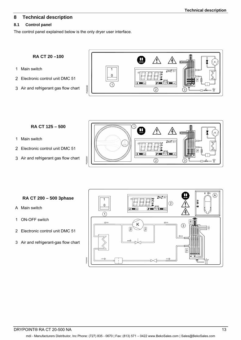
The control panel explained below is the only dryer user interface.
RA CT 20 –100 K
1
2 3PQ
S008
0
1
0
Set
reset
K
1 Main switch
2 Electronic control unit DMC 51
3 Air and refrigerant gas flow chart
RA CT 125 – 500 K
2 3
PQS0
081
1
Set
reset
K
1 Main switch
2 Electronic control unit DMC 51
3 Air and refrigerant gas flow chart
RA CT 200 – 500 3phase
K 3
A
PQ
S00
82
T4 T3
T1
T2
0
1
1
2Set
reset
K
A Main switch
1 ON-OFF switch
2 Electronic control unit DMC 51
3 Air and refrigerant-gas flow chart
mdi - Manufacturers Distributor, Inc Phone: (727) 835 - 0670 | Fax: (813) 571 – 0422 www.BekoSales.com | [email protected]
Technical description
14 DRYPOINT® RA CT 20-500 NA
8.2 Functional description
Operating principle – All dryer models described in this manual function according to the same principle. The hot and moisture-loaded air is led into an air/air heat exchanger. Afterwards, the air flows through an evaporator, which is also known as an air/refrigerant heat exchanger. The air temperature is reduced to approximately 36°F (2°C), so that water vapour condenses to liquid. The continuously accumulating condensate is collected in the separator to be discharged via the condensate drain. Subsequently, the cold and dry air is led through the air/air heat exchanger, so that it is reheated to up to 46°F (8°C) below the inlet temperature when leaving the dryer.
Refrigeration cycle – The refrigerant is conducted through the compressor and reaches a condenser under high pressure. There, cooling-down takes place, making the refrigerant condense to a liquid state which is under high pressure. The liquid is pressed through a capillary tube where the resulting pressure drop ensures that the refrigerant evaporates at a defined temperature. The liquid refrigerant which is under low pressure is led into the heat exchanger, where it expands. The cold resulting from the expansion serves to cool down the compressed air in the heat exchanger. During this process, the refrigerant evaporates. The low-pressure gas is resupplied to the compressor, where it is compressed again.
Operation in cycling mode (Energy Saving, ESS=YES – see section 8.12.7) – The DMC51 electronic controller constantly monitors the temperature of the DewPoint. In low load conditions, the temperature of the DewPoint tends to fall close to the freezing point, at this point the DMC51 controls the switching off of the compressor.
The compressor will be started again when the DewPoint temperature rises above a target value. To avoid an excessive number of cycles, DMC51 keeps the compressor on for a minimum time (about 6 minutes) within which, if necessary, will activate a solenoid valve EVH that enables the operation of the hot gas by-pass valve. In this way the compressor cannot make more than 10 cycles per hour. The solenoid valve EVL and the check valve CHV (where installed) help to extend the off time of the compressor and avoid the immediate balancing of high and low pressures of the refrigerant circuit. The solenoid valve EVL is activated before the compressor to balance the pressures and is kept active for the entire time during which the compressor is on.
With these dryers, the energy consumption will be adjusted closely proportional to the thermal load applied to the dryer itself, allowing considerable energy savings in the majority of applications.
Operation in hot gas by-pass mode (NO Energy Saving, ESS=NO – see section 8.12.7) – The DMC51 electronic controller constantly keep activated the compressor, the solenoid valve EVH and the solenoid valve EVL. In cases of a reduced compressed-air load, the excess refrigerant is bypassed automatically to the compressor via the hot gas bypass valve.
mdi - Manufacturers Distributor, Inc Phone: (727) 835 - 0670 | Fax: (813) 571 – 0422 www.BekoSales.com | [email protected]
Technical description
DRYPOINT® RA CT 20-500 NA 15
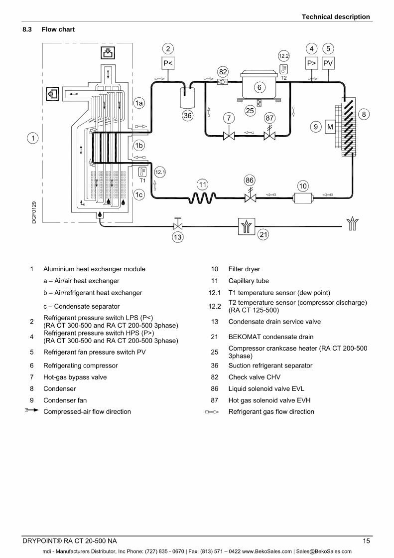
8.3 Flow chart
13
1
1c
T1
1b
1a
10
6
9 M
8
DG
F012
9
21
12.1
36
8611
87
82
7
T2
12.2
25
P<
2 4
P>
5
PV
1 Aluminium heat exchanger module 10 Filter dryer
a – Air/air heat exchanger 11 Capillary tube
b – Air/refrigerant heat exchanger 12.1 T1 temperature sensor (dew point)
c – Condensate separator 12.2 T2 temperature sensor (compressor discharge) (RA CT 125-500)
2 Refrigerant pressure switch LPS (P<) (RA CT 300-500 and RA CT 200-500 3phase) 13 Condensate drain service valve
4 Refrigerant pressure switch HPS (P>) (RA CT 300-500 and RA CT 200-500 3phase) 21 BEKOMAT condensate drain
5 Refrigerant fan pressure switch PV 25 Compressor crankcase heater (RA CT 200-500 3phase)
6 Refrigerating compressor 36 Suction refrigerant separator
7 Hot-gas bypass valve 82 Check valve CHV
8 Condenser 86 Liquid solenoid valve EVL
9 Condenser fan 87 Hot gas solenoid valve EVH Compressed-air flow direction Refrigerant gas flow direction
mdi - Manufacturers Distributor, Inc Phone: (727) 835 - 0670 | Fax: (813) 571 – 0422 www.BekoSales.com | [email protected]
Technical description
16 DRYPOINT® RA CT 20-500 NA
8.4 Refrigerating compressor
The employed refrigerating compressors are constructed by leading manufacturers. The hermetically sealed construction is absolutely gastight. The integrated safeguard protects the compressor against overheating and excess current. The protection is automatically reset as soon as the nominal conditions are reached again.
8.5 Condenser
The condenser is the component in which the gas coming from the compressor is cooled down, condensed and liquefied. Under no circumstances must the temperature of the ambient air exceed the nominal values. It is also important that the condenser unit is kept free from dust and other impurities.
8.6 Filter dryer
Despite controlled vacuuming, traces of moisture can accumulate in the refrigeration cycle. The filter dryer serves to absorb this moisture and to bond it.
8.7 Capillary tube
The capillary tube is a copper tube with a reduced diameter which is located between the condenser and the evaporator, serving as a restrictor to reduce the pressure of the refrigerant. The pressure reduction serves to reach an optimum temperature inside of the evaporator. The lower the outlet pressure at the capillary tube, the lower the evaporation temperature. The length and the inner diameter of the capillary tube are exactly dimensioned to ensure the performance of the dryer. Settings or maintenance works are not required.
8.8 Aluminium heat exchanger
The heat exchanger module consists of an air/air heat exchanger, an air/refrigerant heat exchanger, and of a high-performance separator. The compressed air flows top-down through the heat exchanger. The large cross-sections of the flow passages cause low flow rates and low compressed-air losses. In the air/air heat exchanger, the heat exchange is effected in a reverse current. This guarantees maximum heat transfer. The heat transfer in the air/refrigerant heat exchanger also takes place in a reverse current. This allows full evaporation of the refrigerant. The high-performance separator ensures almost complete separation of the condensate. Maintenance of the high-performance separator is not required.
mdi - Manufacturers Distributor, Inc Phone: (727) 835 - 0670 | Fax: (813) 571 – 0422 www.BekoSales.com | [email protected]
Technical description
DRYPOINT® RA CT 20-500 NA 17
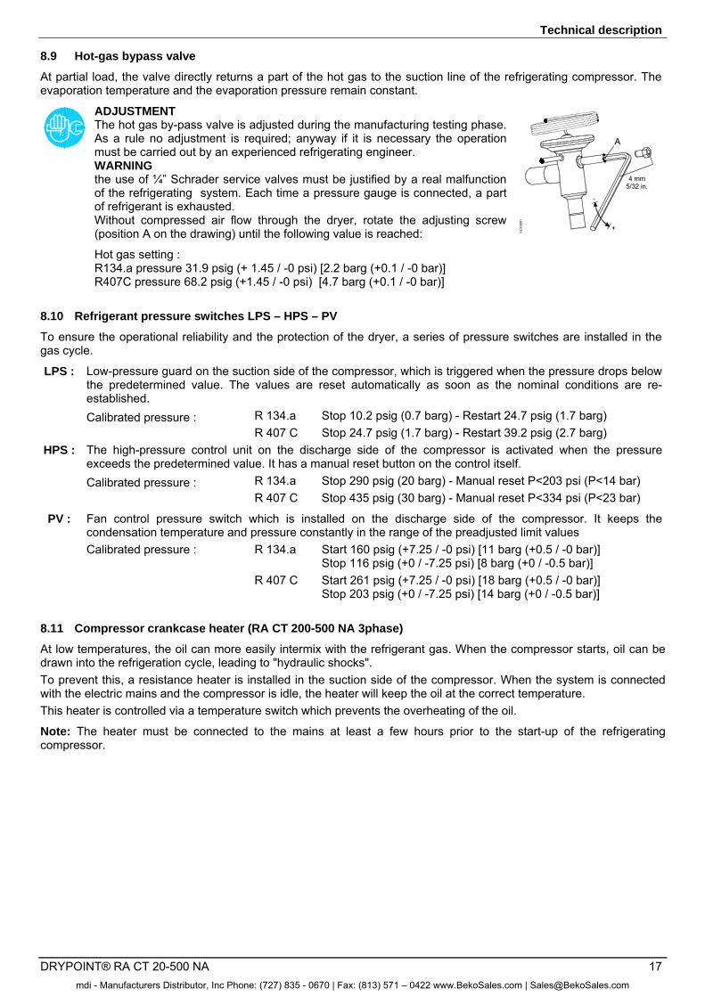
8.9 Hot-gas bypass valve
At partial load, the valve directly returns a part of the hot gas to the suction line of the refrigerating compressor. The evaporation temperature and the evaporation pressure remain constant.
ADJUSTMENT The hot gas by-pass valve is adjusted during the manufacturing testing phase. As a rule no adjustment is required; anyway if it is necessary the operation must be carried out by an experienced refrigerating engineer. WARNING the use of ¼” Schrader service valves must be justified by a real malfunction of the refrigerating system. Each time a pressure gauge is connected, a part of refrigerant is exhausted. Without compressed air flow through the dryer, rotate the adjusting screw (position A on the drawing) until the following value is reached:
Hot gas setting : R134.a pressure 31.9 psig (+ 1.45 / -0 psi) [2.2 barg (+0.1 / -0 bar)] R407C pressure 68.2 psig (+1.45 / -0 psi) [4.7 barg (+0.1 / -0 bar)]
A
4 mm5/32 in.
+
-
VLY
0001
8.10 Refrigerant pressure switches LPS – HPS – PV
To ensure the operational reliability and the protection of the dryer, a series of pressure switches are installed in the gas cycle.
LPS : Low-pressure guard on the suction side of the compressor, which is triggered when the pressure drops below the predetermined value. The values are reset automatically as soon as the nominal conditions are re-established.
Calibrated pressure : R 134.a Stop 10.2 psig (0.7 barg) - Restart 24.7 psig (1.7 barg) R 407 C Stop 24.7 psig (1.7 barg) - Restart 39.2 psig (2.7 barg) HPS : The high-pressure control unit on the discharge side of the compressor is activated when the pressure
exceeds the predetermined value. It has a manual reset button on the control itself. Calibrated pressure : R 134.a Stop 290 psig (20 barg) - Manual reset P<203 psi (P<14 bar) R 407 C Stop 435 psig (30 barg) - Manual reset P<334 psi (P<23 bar)
PV : Fan control pressure switch which is installed on the discharge side of the compressor. It keeps the condensation temperature and pressure constantly in the range of the preadjusted limit values
Calibrated pressure : R 134.a Start 160 psig (+7.25 / -0 psi) [11 barg (+0.5 / -0 bar)] Stop 116 psig (+0 / -7.25 psi) [8 barg (+0 / -0.5 bar)]
R 407 C Start 261 psig (+7.25 / -0 psi) [18 barg (+0.5 / -0 bar)] Stop 203 psig (+0 / -7.25 psi) [14 barg (+0 / -0.5 bar)]
8.11 Compressor crankcase heater (RA CT 200-500 NA 3phase)
At low temperatures, the oil can more easily intermix with the refrigerant gas. When the compressor starts, oil can be drawn into the refrigeration cycle, leading to "hydraulic shocks". To prevent this, a resistance heater is installed in the suction side of the compressor. When the system is connected with the electric mains and the compressor is idle, the heater will keep the oil at the correct temperature. This heater is controlled via a temperature switch which prevents the overheating of the oil.
Note: The heater must be connected to the mains at least a few hours prior to the start-up of the refrigerating compressor.
mdi - Manufacturers Distributor, Inc Phone: (727) 835 - 0670 | Fax: (813) 571 – 0422 www.BekoSales.com | [email protected]
Technical description
18 DRYPOINT® RA CT 20-500 NA
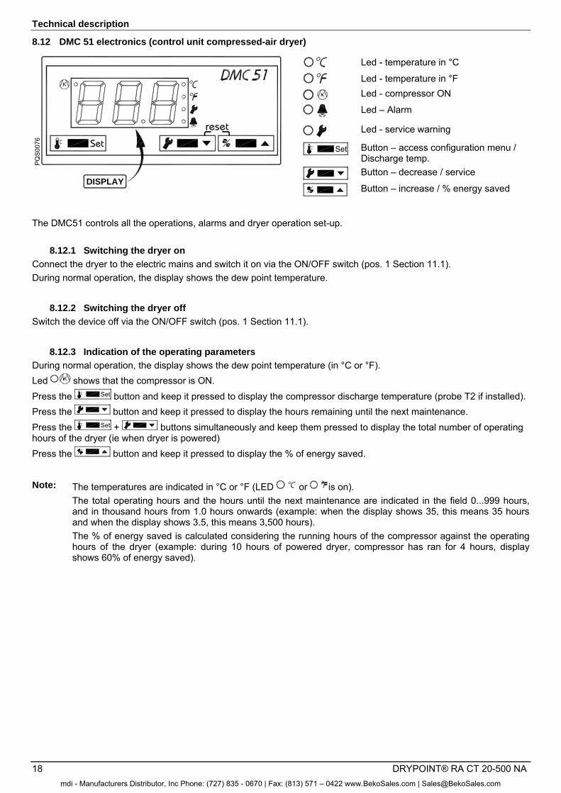
8.12 DMC 51 electronics (control unit compressed-air dryer)
Set
PQ
S00
7 6
DISPLAY
reset
K
Led - temperature in °C
Led - temperature in °F Led - compressor ON
Led – Alarm
Led - service warning
Set Button – access configuration menu / Discharge temp. Button – decrease / service
Button – increase / % energy saved
The DMC51 controls all the operations, alarms and dryer operation set-up.
8.12.1 Switching the dryer on
Connect the dryer to the electric mains and switch it on via the ON/OFF switch (pos. 1 Section 11.1). During normal operation, the display shows the dew point temperature.
8.12.2 Switching the dryer off
Switch the device off via the ON/OFF switch (pos. 1 Section 11.1).
8.12.3 Indication of the operating parameters
During normal operation, the display shows the dew point temperature (in °C or °F). Led shows that the compressor is ON. Press the Set button and keep it pressed to display the compressor discharge temperature (probe T2 if installed). Press the button and keep it pressed to display the hours remaining until the next maintenance. Press the Set + buttons simultaneously and keep them pressed to display the total number of operating hours of the dryer (ie when dryer is powered) Press the button and keep it pressed to display the % of energy saved.
Note: The temperatures are indicated in °C or °F (LED or is on). The total operating hours and the hours until the next maintenance are indicated in the field 0...999 hours, and in thousand hours from 1.0 hours onwards (example: when the display shows 35, this means 35 hours and when the display shows 3.5, this means 3,500 hours). The % of energy saved is calculated considering the running hours of the compressor against the operating hours of the dryer (example: during 10 hours of powered dryer, compressor has ran for 4 hours, display shows 60% of energy saved).
mdi - Manufacturers Distributor, Inc Phone: (727) 835 - 0670 | Fax: (813) 571 – 0422 www.BekoSales.com | [email protected]
Technical description
DRYPOINT® RA CT 20-500 NA 19
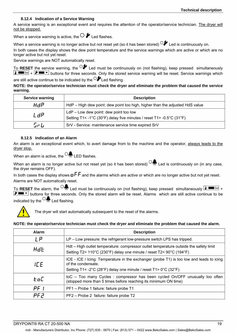
8.12.4 Indication of a Service Warning
A service warning is an exceptional event and requires the attention of the operator/service technician. The dryer will not be stopped.
When a service warning is active, the Led flashes.
When a service warning is no longer active but not reset yet (so it has been stored) Led is continuously on. In both cases the display shows the dew point temperature and the service warnings which are active or which are no longer active but not yet reset. Service warnings are NOT automatically reset.
To RESET the service warning, the Led must be continuously on (not flashing), keep pressed simultaneously Set + buttons for three seconds. Only the stored service warning will be reset. Service warnings which
are still active continue to be indicated by the Led flashing. NOTE: the operator/service technician must check the dryer and eliminate the problem that caused the service warning.
Service warning Description
HdP – High dew point: dew point too high, higher than the adjusted HdS value
LdP – Low dew point: dew point too low Setting T1< -1°C (30°F) delay five minutes / reset T1> -0.5°C (31°F)
SrV - Service: maintenance service time expired SrV
8.12.5 Indication of an Alarm
An alarm is an exceptional event which, to avert damage from to the machine and the operator, always leads to the dryer stop.
When an alarm is active, the LED flashes.
When an alarm is no longer active but not reset yet (so it has been stored) Led is continuously on (in any case, the dryer remains OFF). In both cases the display shows and the alarms which are active or which are no longer active but not yet reset. Alarms are NOT automatically reset.
To RESET the alarm, the Led must be continuously on (not flashing), keep pressed simultaneously Set + buttons for three seconds. Only the stored alarm will be reset. Alarms which are still active continue to be
indicated by the Led flashing.
The dryer will start automatically subsequent to the reset of the alarms.
NOTE: the operator/service technician must check the dryer and eliminate the problem that caused the alarm.
Alarm Description
LP – Low pressure: the refrigerant low-pressure switch LPS has tripped.
Hdt – High outlet temperature: compressor outlet temperature outside the safety limit Setting T2> 110°C (230°F) delay one minute / reset T2< 90°C (194°F)
ICE - ICE / Icing: Temperature in the exchanger (probe T1) is too low and leads to icing of the condensate. Setting T1< -2°C (28°F) delay one minute / reset T1> 0°C (32°F)
toC – Too many Cycles : compressor has been cycled On/OFF unusually too often (stopped more than 5 times before reaching its minimum ON time)
PF1 – Probe 1 failure: failure probe T1
PF2 – Probe 2 failure: failure probe T2
mdi - Manufacturers Distributor, Inc Phone: (727) 835 - 0670 | Fax: (813) 571 – 0422 www.BekoSales.com | [email protected]
Technical description
20 DRYPOINT® RA CT 20-500 NA
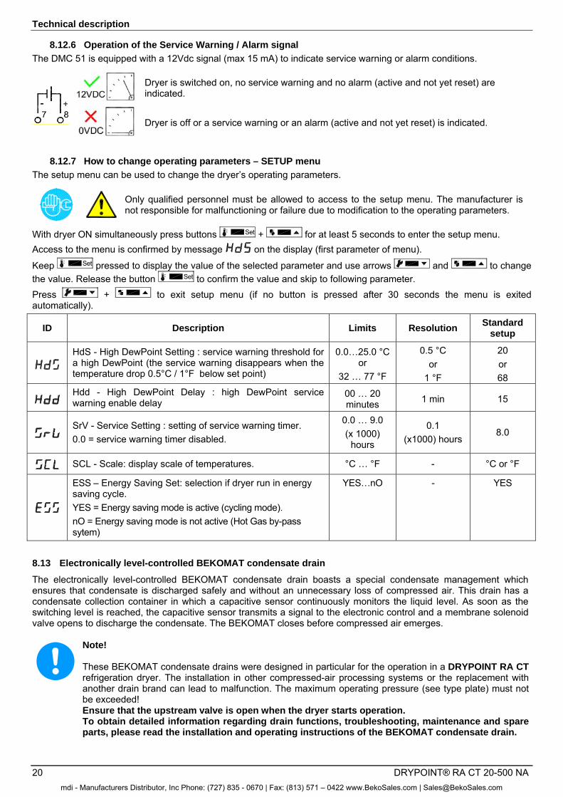
8.12.6 Operation of the Service Warning / Alarm signal
The DMC 51 is equipped with a 12Vdc signal (max 15 mA) to indicate service warning or alarm conditions.
Dryer is switched on, no service warning and no alarm (active and not yet reset) are indicated.
Dryer is off or a service warning or an alarm (active and not yet reset) is indicated.
8.12.7 How to change operating parameters – SETUP menu
The setup menu can be used to change the dryer’s operating parameters.
Only qualified personnel must be allowed to access to the setup menu. The manufacturer is not responsible for malfunctioning or failure due to modification to the operating parameters.
With dryer ON simultaneously press buttons Set + for at least 5 seconds to enter the setup menu. Access to the menu is confirmed by message on the display (first parameter of menu).
Keep Set pressed to display the value of the selected parameter and use arrows and to change the value. Release the button Set to confirm the value and skip to following parameter. Press + to exit setup menu (if no button is pressed after 30 seconds the menu is exited automatically).
ID Description Limits Resolution Standard
setup
HdS - High DewPoint Setting : service warning threshold for a high DewPoint (the service warning disappears when the temperature drop 0.5°C / 1°F below set point)
0.0…25.0 °C or
32 … 77 °F
0.5 °C or
1 °F
20 or 68
Hdd - High DewPoint Delay : high DewPoint service warning enable delay
00 … 20 minutes 1 min 15
SrV - Service Setting : setting of service warning timer. 0.0 = service warning timer disabled.
0.0 … 9.0 (x 1000)
hours
0.1 (x1000) hours
8.0
SCL - Scale: display scale of temperatures. °C … °F - °C or °F
ESS – Energy Saving Set: selection if dryer run in energy saving cycle. YES = Energy saving mode is active (cycling mode). nO = Energy saving mode is not active (Hot Gas by-pass sytem)
YES…nO - YES
8.13 Electronically level-controlled BEKOMAT condensate drain
The electronically level-controlled BEKOMAT condensate drain boasts a special condensate management which ensures that condensate is discharged safely and without an unnecessary loss of compressed air. This drain has a condensate collection container in which a capacitive sensor continuously monitors the liquid level. As soon as the switching level is reached, the capacitive sensor transmits a signal to the electronic control and a membrane solenoid valve opens to discharge the condensate. The BEKOMAT closes before compressed air emerges.
Note! These BEKOMAT condensate drains were designed in particular for the operation in a DRYPOINT RA CT refrigeration dryer. The installation in other compressed-air processing systems or the replacement with another drain brand can lead to malfunction. The maximum operating pressure (see type plate) must not be exceeded! Ensure that the upstream valve is open when the dryer starts operation. To obtain detailed information regarding drain functions, troubleshooting, maintenance and spare parts, please read the installation and operating instructions of the BEKOMAT condensate drain.
mdi - Manufacturers Distributor, Inc Phone: (727) 835 - 0670 | Fax: (813) 571 – 0422 www.BekoSales.com | [email protected]
Installation
DRYPOINT® RA CT 20-500 NA 21
9 Installation
9.1 Place of installation
Note!
Ambient conditions!
In the event that the dryer is not installed under suitable ambient conditions, the ability of the device to condense refrigerant gas is impaired. This can result in a higher load of the refrigerating compressor, and in a loss of efficiency and performance of the dryer. This in turn leads to overheated condenser fan motors, to malfunction of electric components and to a breakdown of the dryer. Failures of this type will affect warranty considerations. Do not install the dryer in an environment in which chemicals with a corrosive effect, explosive gases, toxic gases, evaporation heat, high ambient temperatures or extreme dust and dirt can be found.
Minimum installation requirements:
• Choose an area which is clean and dry, free from dust and protected against atmospheric disturbances. • The load-bearing zone must be even, horizontal and able to bear the weight of the dryer. • Minimum ambient temperature 34°F (+1°C). • Maximum ambient temperature +122°F (+50°C). • Ensure a proper cooling air replacement. • Allow a sufficient clearance on each side of the dryer for proper ventilation and to facilitate maintenance operations.
The dryer does not require attachment to the floor surface.
Do not obstruct the ventilation grille.
Prevent any recirculation of the outgoing cooling air. Protect the dryer against draughts.
Note!
Dryers models RA CT 20 – 75 can be wall-mounted. See fixing dimensions on dimensional drawings in the appendices section. The hanging mounting inevitably causes the obstruction of the ventilation grid positioned on the panel facing the wall fixing. This obstruction, in any case, does not prejudge the efficiency of the ventilation inside the dryer which is guaranteed by other grids on the other panels.
mdi - Manufacturers Distributor, Inc Phone: (727) 835 - 0670 | Fax: (813) 571 – 0422 www.BekoSales.com | [email protected]
Installation
22 DRYPOINT® RA CT 20-500 NA
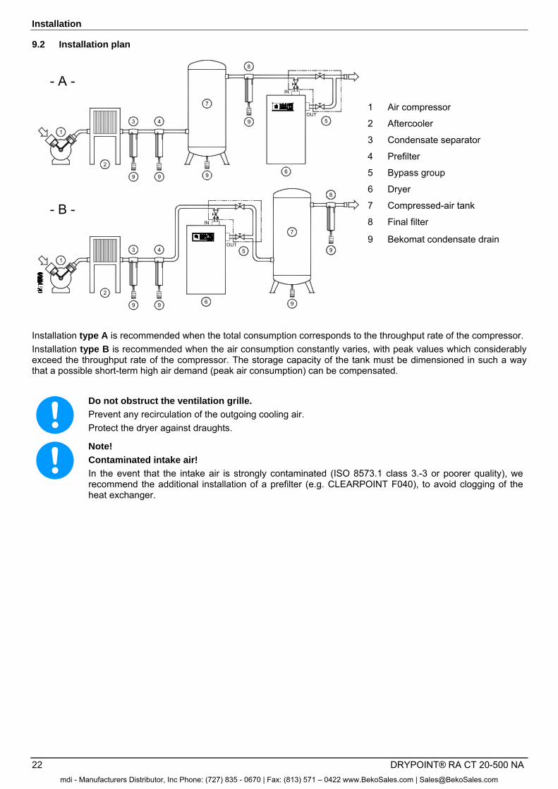
9.2 Installation plan
2
2
1
IN
OUT
7
- A -
- B -
1
7
6
IN
OUT5
9
8
9
4
9
3
9
9 9
3 4
9
9
8
6
5
1 Air compressor
2 Aftercooler
3 Condensate separator
4 Prefilter
5 Bypass group
6 Dryer
7 Compressed-air tank
8 Final filter
9 Bekomat condensate drain
Installation type A is recommended when the total consumption corresponds to the throughput rate of the compressor. Installation type B is recommended when the air consumption constantly varies, with peak values which considerably exceed the throughput rate of the compressor. The storage capacity of the tank must be dimensioned in such a way that a possible short-term high air demand (peak air consumption) can be compensated.
Do not obstruct the ventilation grille.
Prevent any recirculation of the outgoing cooling air. Protect the dryer against draughts.
Note!
Contaminated intake air!
In the event that the intake air is strongly contaminated (ISO 8573.1 class 3.-3 or poorer quality), we recommend the additional installation of a prefilter (e.g. CLEARPOINT F040), to avoid clogging of the heat exchanger.
mdi - Manufacturers Distributor, Inc Phone: (727) 835 - 0670 | Fax: (813) 571 – 0422 www.BekoSales.com | [email protected]
Installation
DRYPOINT® RA CT 20-500 NA 23
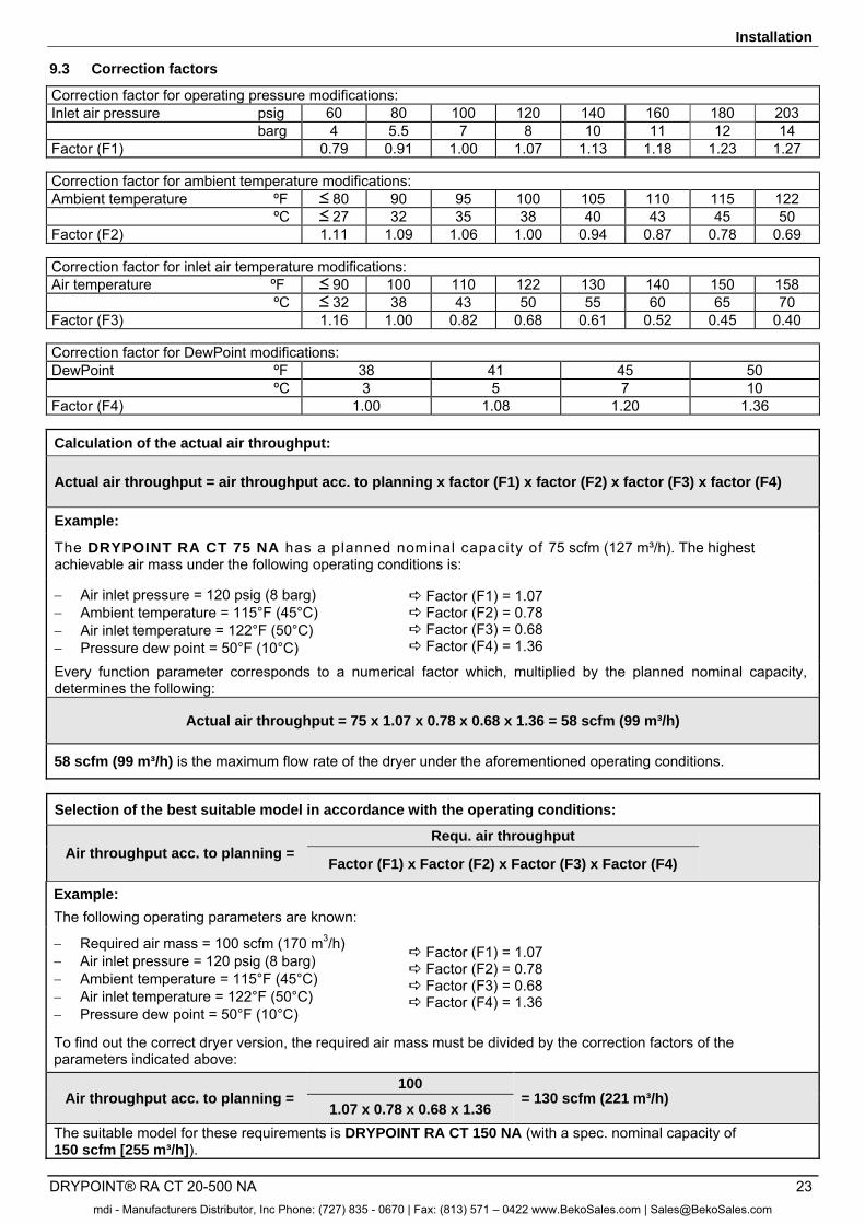
9.3 Correction factors
Correction factor for operating pressure modifications: Inlet air pressure psig 60 80 100 120 140 160 180 203
barg 4 5.5 7 8 10 11 12 14 Factor (F1) 0.79 0.91 1.00 1.07 1.13 1.18 1.23 1.27
Correction factor for ambient temperature modifications: Ambient temperature ºF 80 90 95 100 105 110 115 122
ºC 27 32 35 38 40 43 45 50 Factor (F2) 1.11 1.09 1.06 1.00 0.94 0.87 0.78 0.69
Correction factor for inlet air temperature modifications: Air temperature ºF 90 100 110 122 130 140 150 158
ºC 32 38 43 50 55 60 65 70 Factor (F3) 1.16 1.00 0.82 0.68 0.61 0.52 0.45 0.40 Correction factor for DewPoint modifications: DewPoint ºF 38 41 45 50
ºC 3 5 7 10 Factor (F4) 1.00 1.08 1.20 1.36
Calculation of the actual air throughput:
Actual air throughput = air throughput acc. to planning x factor (F1) x factor (F2) x factor (F3) x factor (F4)
Example:
The DRYPOINT RA CT 75 NA has a planned nominal capacity of 75 scfm (127 m³/h). The highest achievable air mass under the following operating conditions is:
Air inlet pressure = 120 psig (8 barg) Ambient temperature = 115°F (45°C) Air inlet temperature = 122°F (50°C) Pressure dew point = 50°F (10°C)
Factor (F1) = 1.07 Factor (F2) = 0.78 Factor (F3) = 0.68 Factor (F4) = 1.36
Every function parameter corresponds to a numerical factor which, multiplied by the planned nominal capacity, determines the following:
Actual air throughput = 75 x 1.07 x 0.78 x 0.68 x 1.36 = 58 scfm (99 m³/h)
58 scfm (99 m³/h) is the maximum flow rate of the dryer under the aforementioned operating conditions.
Selection of the best suitable model in accordance with the operating conditions:
Air throughput acc. to planning = Requ. air throughput
Factor (F1) x Factor (F2) x Factor (F3) x Factor (F4)
Example: The following operating parameters are known:
Required air mass = 100 scfm (170 m3/h) Air inlet pressure = 120 psig (8 barg) Ambient temperature = 115°F (45°C) Air inlet temperature = 122°F (50°C) Pressure dew point = 50°F (10°C)
Factor (F1) = 1.07 Factor (F2) = 0.78 Factor (F3) = 0.68 Factor (F4) = 1.36
To find out the correct dryer version, the required air mass must be divided by the correction factors of the parameters indicated above:
Air throughput acc. to planning = 100
= 130 scfm (221 m³/h) 1.07 x 0.78 x 0.68 x 1.36
The suitable model for these requirements is DRYPOINT RA CT 150 NA (with a spec. nominal capacity of 150 scfm [255 m³/h]).
mdi - Manufacturers Distributor, Inc Phone: (727) 835 - 0670 | Fax: (813) 571 – 0422 www.BekoSales.com | [email protected]
Installation
24 DRYPOINT® RA CT 20-500 NA
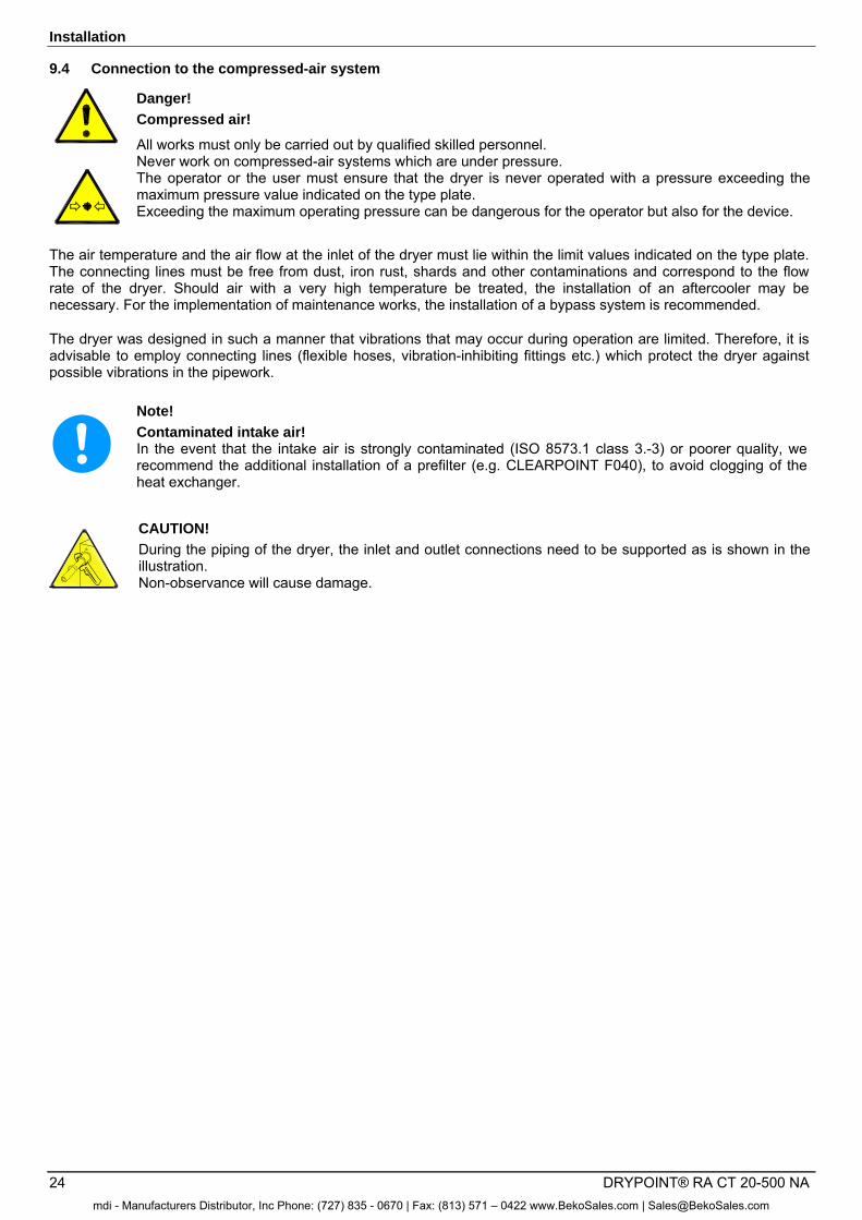
9.4 Connection to the compressed-air system
Danger!
Compressed air!
All works must only be carried out by qualified skilled personnel. Never work on compressed-air systems which are under pressure. The operator or the user must ensure that the dryer is never operated with a pressure exceeding the maximum pressure value indicated on the type plate. Exceeding the maximum operating pressure can be dangerous for the operator but also for the device.
The air temperature and the air flow at the inlet of the dryer must lie within the limit values indicated on the type plate. The connecting lines must be free from dust, iron rust, shards and other contaminations and correspond to the flow rate of the dryer. Should air with a very high temperature be treated, the installation of an aftercooler may be necessary. For the implementation of maintenance works, the installation of a bypass system is recommended.
The dryer was designed in such a manner that vibrations that may occur during operation are limited. Therefore, it is advisable to employ connecting lines (flexible hoses, vibration-inhibiting fittings etc.) which protect the dryer against possible vibrations in the pipework. ===== Ende der Stückliste =====
Note!
Contaminated intake air! In the event that the intake air is strongly contaminated (ISO 8573.1 class 3.-3) or poorer quality, we recommend the additional installation of a prefilter (e.g. CLEARPOINT F040), to avoid clogging of the heat exchanger.
CAUTION! During the piping of the dryer, the inlet and outlet connections need to be supported as is shown in the illustration. Non-observance will cause damage.
mdi - Manufacturers Distributor, Inc Phone: (727) 835 - 0670 | Fax: (813) 571 – 0422 www.BekoSales.com | [email protected]
Installation
DRYPOINT® RA CT 20-500 NA 25
9.5 Electrical connections
Danger! Supply voltage!
The connection to the electric mains should only be carried out by qualified skilled personnel and must correspond to the legal provisions in force in your region.
Prior to connecting the device, please check the type plate to avoid exceeding the indicated values. The voltage tolerance is +/- 10%. DRYPOINT RA CT 20-500 NA dryers are supplied with a power cord and safety plug (two-pole and earth connection). or with a junction box on the back plate. Make sure that suitable fuses or circuit breakers in accordance with the indications on the type plate are available. A residual-current device (RCD) with In =0.03A is suggested. The cross-section of the power supply cable must correspond to the power consumption of the dryer. In this respect, the ambient temperature, the cable laying conditions, the length of the cables and the requirements of the local electricity supplier need to be considered.
Danger!
Supply voltage and missing earth connection! Important: ensure that the plant is connected to earth-ground. Do not use plug adapters at the power plug. Possible replacement of the power plug must only be carried out by a qualified electrician.
9.6 Condensate drain
Danger! Compressed air and condensate under pressure!
The condensate is discharged at system pressure. The drain pipe needs to be secured. Never direct the condensate drain pipe at persons.
The dryer is delivered with an already integrated electronically level-controlled BEKOMAT condensate drain. Connect the condensate drain with a collection system or container by properly screwing it on. Do not connect the drain with pressurised plants.
Do not discharge the condensate into the environment. The condensate accumulating in the dryer contains oil particles which were released into the air by the compressor. Dispose of the condensate in accordance with the local provisions. It is advisable to install a water-oil separator, to which the total amount of condensate from the compressors, dryers, tanks, filters etc. is supplied. We recommend ÖWAMAT oil-water separators for dispersed compressor condensate and BEKOSPLIT emulsion-splitting plants for emulsified condensate.
mdi - Manufacturers Distributor, Inc Phone: (727) 835 - 0670 | Fax: (813) 571 – 0422 www.BekoSales.com | [email protected]
Start-up
26 DRYPOINT® RA CT 20-500 NA
10 Start-up
10.1 Preliminary stages
Note!
Exceeding of the operating parameters!
Ensure that the operating parameters comply with the nominal values indicated on the type plate of the dryer (voltage, frequency, air pressure, air temperature, ambient temperature etc.).
Prior to delivery, this dryer was thoroughly tested, checked and packed. Please verify the reliability of the dryer during the initial start-up and check the perfect functioning during the first operating hours.
The initial start-up must be carried out by qualified personnel. During the installation and operation of this device, all national regulations regarding electronics and any other federal and state ordinances, as well as local provisions, need to be adhered to. The operator and the user must ensure that the dryer is not operated without panels.
10.2 Initial start-up
Note!
The number of starts/stops by pressing the ON-OFF switch - pos. 1 control panel must be limited to six per hour. Irreparable damage can be caused by starting up the device too often.
The method below should be applied during the first start-up, after longer downtimes or subsequent to maintenance works. The start-up must be carried out by certified skilled personnel.
Processing sequence (see Section 11.1 "Control panel")
1. Ensure that all steps of the "Installation" chapter have been carried correctly. 2. Ensure that the connection to the compressed-air system is in accordance with the provisions and that the lines
are fixed and supported properly. 3. Ensure that the condensate drain pipe is fixed in accordance with the provisions and that it is connected with a
collection system or a container and open the drain service valve. 4. Ensure that the bypass system (if installed) is open and that the dryer is disconnected from the compressed-air
system. 5. Remove any packaging material and other items which may block the space around the dryer. 6. Establish the mains connection (plug into socket). 7. RA CT 200-500 3phase - switch on the main switch - pos. A control panel. 8. NOTE! RA CT 200-500 3phase - wait at least two hours before starting the dryer (the crankcase heater of the
compressor needs to heat up the compressor oil). 9. Start the dryer by switching on the ON-OFF switch on the control panel (pos. 1). 10. Make sure that the DMC 51 electronic control unit is switched on. 11. If the temperature displayed on the DMC51 electronic control unit is sufficiently high, verify that the refrigerating
compressor starts within a few minutes. NOTE! – With low temperatures, the refrigerating compressor will remain OFF
12. Ensure that the fan runs properly – wait for the first interventions. 13. Wait until the dew point remains stable. 14. Slowly open the air inlet valve. 15. Slowly open the air outlet valve. 16. Slowly close the central bypass valve of the system (if installed). 17. Check the pipes for air leakage. 18. Ensure the proper functioning of the condensate drain cycle (wait for the first condensate discharges).
Note!
A dew point between 32°F (0°C) and +50°F (+10°C) displayed on the DMC 51 control unit is considered to be correct according to the possible operating conditions (flow rate, air inlet temperature, ambient temperature etc.).
mdi - Manufacturers Distributor, Inc Phone: (727) 835 - 0670 | Fax: (813) 571 – 0422 www.BekoSales.com | [email protected]
Start-up
DRYPOINT® RA CT 20-500 NA 27
In the cycling operating mode (Energy Saving, ESS=YES – see section 8.12.7), the refigerating compressor is switched ON and OFF by the DMC51 electronic control unit, according to thermal load applied to the dryer. The dryer needs to be switched on during the entire compressed-air usage time, even if the compressed-air compressor works periodically.
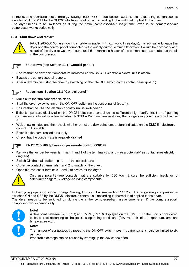
10.3 Shut down and restart
RA CT 200-500 3phase - during short-term inactivity (max. two to three days), it is advisable to leave the dryer and the control panel connected to the supply current circuit. Otherwise, it would be necessary at a restart of the dryer to wait two hours, until the crankcase heater of the compressor has heated up the oil in the compressor.
Shut down (see Section 11.1 "Control panel")
• Ensure that the dew point temperature indicated on the DMC 51 electronic control unit is stable. • Bypass the compressed-air supply. • After a few minutes, stop the dryer by switching off the ON-OFF switch on the control panel (pos. 1).
Restart (see Section 11.1 "Control panel")
• Make sure that the condenser is clean. • Start the dryer by switching on the ON-OFF switch on the control panel (pos. 1). • Ensure that the DMC 51 electronic control unit is switched on. • If the temperature displayed on the DMC51 electronic control unit is sufficiently high, verify that the refrigerating
compressor starts within a few minutes. NOTE! – With low temperatures, the refrigerating compressor will remain OFF
• Wait a few minutes and then check whether or not the dew point temperature indicated on the DMC 51 electronic control unit is stable
• Establish the compressed-air supply. • Check that the condensate is regularly drained
RA CT 200-500 3phase - dryer remote control ON/OFF
• Remove the jumper between terminals 1 and 2 of the terminal strip and wire a potential-free contact (see electric diagram).
• Switch ON the main switch - pos. 1 on the control panel. • Close the contact at terminals 1 and 2 to switch on the dryer. • Open the contact at terminals 1 and 2 to switch off the dryer.
Only use potential-free contacts that are suitable for 230 Vac. Ensure the sufficient insulation of potentially dangerous voltage-carrying components.
In the cycling operating mode (Energy Saving, ESS=YES – see section 11.12.7), the refigerating compressor is switched ON and OFF by the DMC51 electronic control unit, according to thermal load applied to the dryer. The dryer needs to be switched on during the entire compressed-air usage time, even if the compressed-air compressor works periodically.
Note! A dew point between 32°F (0°C) and +50°F (+10°C) displayed on the DMC 51 control unit is considered to be correct according to the possible operating conditions (flow rate, air inlet temperature, ambient temperature etc.).
Note!
The number of starts/stops by pressing the ON-OFF switch - pos. 1 control panel should be limited to six per hour. Irreparable damage can be caused by starting up the device too often.
mdi - Manufacturers Distributor, Inc Phone: (727) 835 - 0670 | Fax: (813) 571 – 0422 www.BekoSales.com | [email protected]
Technical data
28 DRYPOINT® RA CT 20-500 NA
11 Technical data
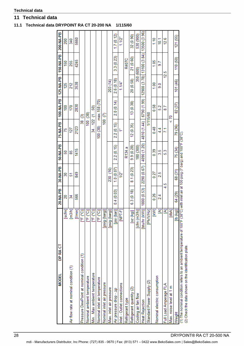
11.1 Technical data DRYPOINT RA CT 20-200 NA 1/115/60
mdi - Manufacturers Distributor, Inc Phone: (727) 835 - 0670 | Fax: (813) 571 – 0422 www.BekoSales.com | [email protected]
Technical data
DRYPOINT® RA CT 20-500 NA 29
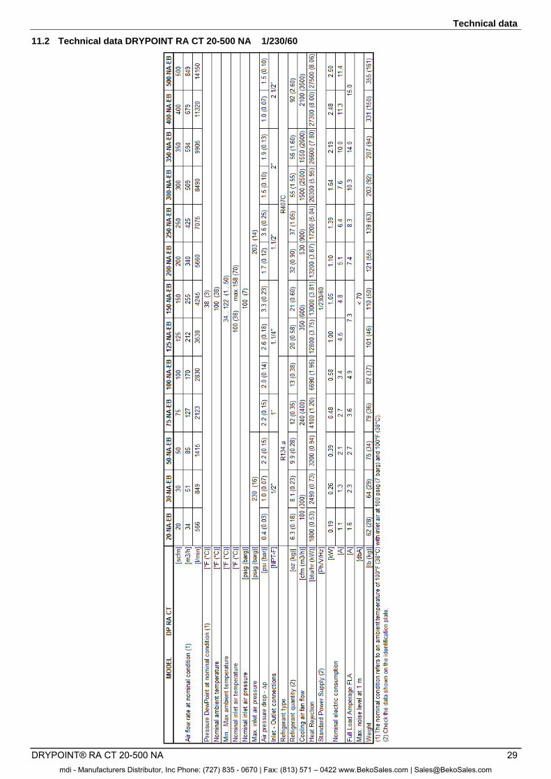
11.2 Technical data DRYPOINT RA CT 20-500 NA 1/230/60
mdi - Manufacturers Distributor, Inc Phone: (727) 835 - 0670 | Fax: (813) 571 – 0422 www.BekoSales.com | [email protected]
Technical data
30 DRYPOINT® RA CT 20-500 NA
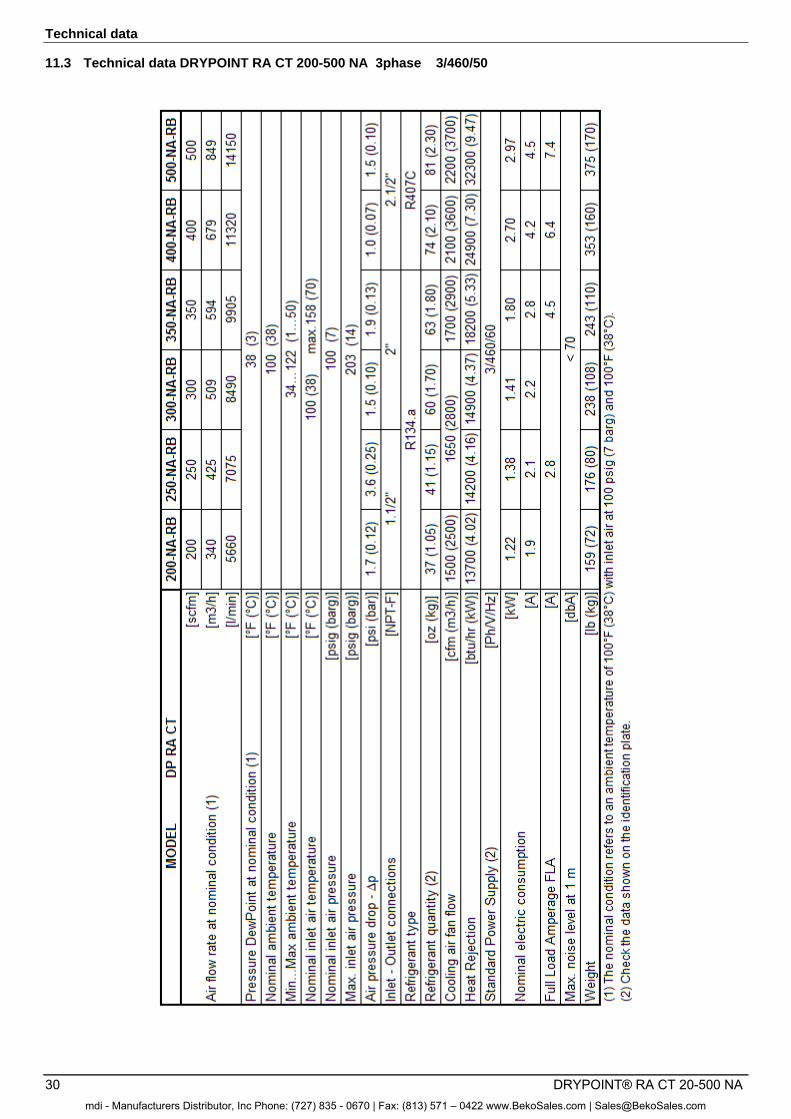
11.3 Technical data DRYPOINT RA CT 200-500 NA 3phase 3/460/50
mdi - Manufacturers Distributor, Inc Phone: (727) 835 - 0670 | Fax: (813) 571 – 0422 www.BekoSales.com | [email protected]
Technical data
DRYPOINT® RA CT 20-500 NA 31
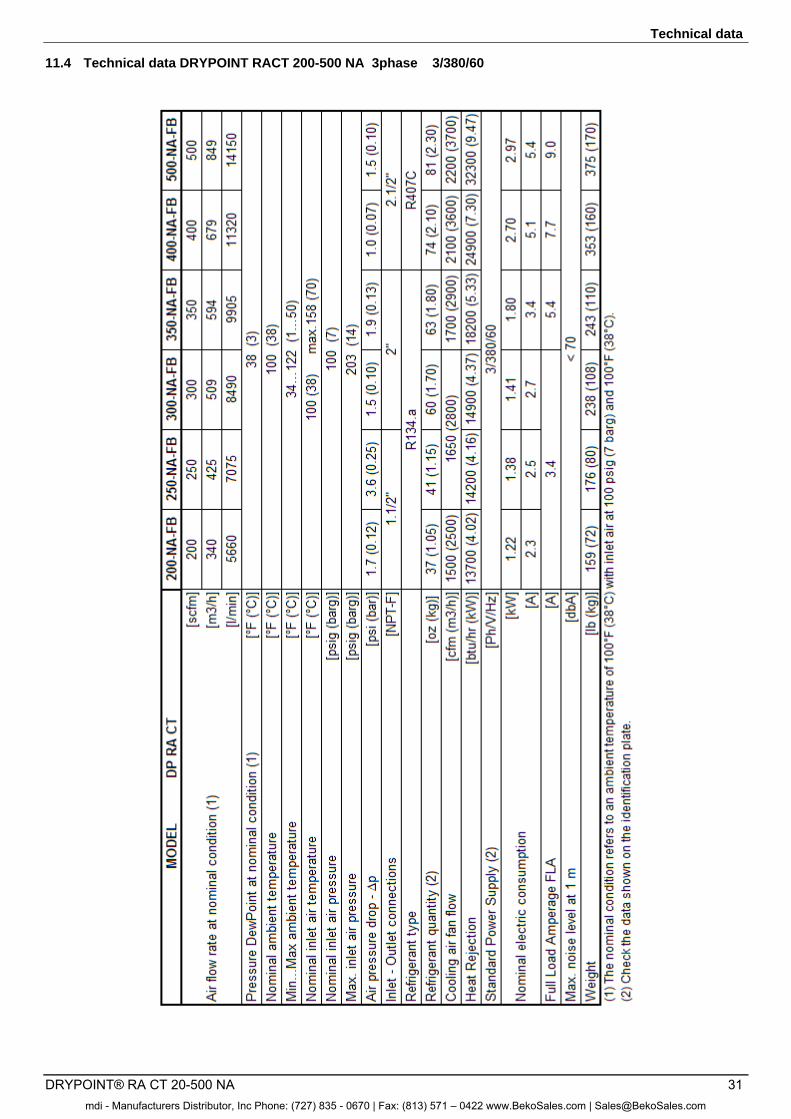
11.4 Technical data DRYPOINT RACT 200-500 NA 3phase 3/380/60
mdi - Manufacturers Distributor, Inc Phone: (727) 835 - 0670 | Fax: (813) 571 – 0422 www.BekoSales.com | [email protected]
Maintenance, troubleshooting, spare parts and dismantling
32 DRYPOINT® RA CT 20-500 NA
12 Maintenance, troubleshooting, spare parts and dismantling
12.1 Checks and maintenance
Certified skilled personnel
Installation works must exclusively be carried out by authorised and qualified skilled personnel. Prior to undertaking any measures on the DRYPOINT® RA CT 20-500 NA compressed-air refrigeration dryer, the certified skilled personnel4 shall read up on the device by carefully studying the operating instructions. The operator is responsible for the adherence to these provisions. The respective directives in force apply to the qualification and expertise of the certified skilled personnel. For safe operation, the device must only be installed and operated in accordance with the indications in the operating instructions. In addition, the national and operational statutory provisions and safety regulations, as well as the accident prevention regulations required for the respective case of application, need to be observed during employment. This applies accordingly when accessories are used.
Danger!
Compressed air!
Risk of serious injury or death through contact with quickly or suddenly escaping compressed air or through bursting and/or unsecured plant components.
Compressed air is a highly dangerous energy source. Never work on the dryer when the system is under pressure. Never direct the compressed-air outlet or condensate drain hoses at persons. The user is responsible for the proper maintenance of the dryer. Non-observance of the instructions in the "Installation" and "Maintenance, troubleshooting, spare parts and dismantling" chapters leads to the expiration of the guarantee. Improper maintenance may result in dangerous situations for the personnel and/or the device.
Danger!
Supply voltage!
Contact with non-insulated parts carrying supply voltage involves the risk of an electric shock resulting in injuries and death.
Only qualified and skilled personnel are authorised to run electrically-operated devices. Prior to undertaking maintenance measures at the device, the following requirements must be met: Make sure that the power supply is switched off and that the device is off and marked for maintenance measures. Please also ensure that the power supply cannot be re-established during the works.
Prior to carrying out maintenance works at the dryer, switch it off and wait for at least 30 minutes.
Caution!
Hot surfaces!
During operation, several components can reach surface temperatures of more than 140°F (60°C). There is the risk of burns.
All components concerned are installed inside of the closed housing. The housing must only be opened by certified skilled personnel. Some components can reach high temperatures during operation. Avoid any contact until the system or the component has cooled down.
4 Certified skilled personnel are persons who are authorised by the manufacturer, with experience and technical training, who are well-grounded in the respective provisions and laws and capable of carrying out the required works and of identifying and avoiding any risks during the machine transport, installation, operation and maintenance. Qualified and authorised operators are persons who are instructed by the manufacturer regarding the handling of the refrigeration system, with experience and technical training, and who are well-grounded in the respective provisions and laws.
mdi - Manufacturers Distributor, Inc Phone: (727) 835 - 0670 | Fax: (813) 571 – 0422 www.BekoSales.com | [email protected]
Maintenance, troubleshooting, spare parts and dismantling
DRYPOINT® RA CT 20-500 NA 33
DAILY:
• Check whether the dew point indicated on the electronics is correct. • Ensure that the condensate drain system functions properly. • Make sure that the condenser is clean.
EVERY 200 HOURS OR MONTHLY
• Clean the condenser using an air jet (max. 2 bar / 30 psig) inside out. Make sure not to damage the aluminium lamellae of the cooling package.
• Finally, verify the operation of the device.
EVERY 1,000 HOURS OR ANNUALLY
• Verify all screws, clamps and connections of the electric system to make sure that they are fastened securely. Check the device for broken and ruptured cables or cables without insulation.
• Check the refrigeration cycle for signs of oil and refrigerant leaks. • Measure the current strength and note it down. Ensure that the read values are within the permissible
limit values, as indicated in the specification table. • Check the hose lines of the condensate drain and replace them, if required. • Finally, verify the operation of the device.
EVERY 8,000 HOURS
• Replace BEKOMAT Service Unit. • Replace compressor operating relay KC (RA CT 125-500 NA)
12.2 Troubleshooting
Certified skilled personnel
Installation works must exclusively be carried out by authorised and qualified skilled personnel. Prior to undertaking any measures on the DRYPOINT® RA CT 20-500 NA compressed-air refrigeration dryer, the certified skilled personnel shall read up on the device by carefully studying the operating instructions. The operator is responsible for the adherence to these provisions. The respective directives in force apply to the qualification and expertise of the certified skilled personnel. For safe operation, the device must only be installed and operated in accordance with the indications in the operating instructions. In addition, the national and operational statutory provisions and safety regulations, as well as the accident prevention regulations required for the respective case of application, need to be observed during employment. This applies accordingly when accessories are used.
Danger!
Compressed air!
Risk of serious injury or death through contact with quickly or suddenly escaping compressed air or through bursting and/or unsecured plant components.
Compressed air is a highly dangerous energy source. Never work on the dryer when the system is under pressure. Never direct the compressed-air outlet or condensate drain hoses at persons. The user is responsible for the proper maintenance of the dryer. Non-observance of the instructions in the "Installation" and "Maintenance, troubleshooting, spare parts and dismantling" chapters leads to the expiration of the guarantee. Improper maintenance may result in dangerous situations for the personnel and/or the device.
Danger!
Supply voltage!
Contact with non-insulated parts carrying supply voltage involves the risk of an electric shock resulting in injuries and death.
Only qualified and skilled personnel are authorised to run electrically-operated devices. Prior to undertaking maintenance measures at the device, the following requirements must be met: Make sure that the power supply is switched off and that the device is off and marked for maintenance measures. Please also ensure that the power supply cannot be re-established during the works.
mdi - Manufacturers Distributor, Inc Phone: (727) 835 - 0670 | Fax: (813) 571 – 0422 www.BekoSales.com | [email protected]
Maintenance, troubleshooting, spare parts and dismantling
34 DRYPOINT® RA CT 20-500 NA
Prior to carrying out maintenance works at the dryer, switch it off and wait for at least 30 minutes.
Caution!
Hot surfaces!
During operation, several components can reach surface temperatures of more than 140°F (60°C). There is the risk of burns.
All components concerned are installed inside of the closed housing. The housing must only be opened by certified skilled personnel. Some components can reach high temperatures during operation. Avoid any contact until the system or the component has cooled down.
FAULT POSSIBLE REASON – SUGGESTED MEASURE
The display of DMC51 is not lit
Verify that the system is powered. Verify the electric wiring. If installed – HPS pressure switch has been activated – see specific point RA CT 200-500 3phase - Blow of fuse (FU2 on the electric diagram) of the auxiliary
circuit - replace it and check the proper operation of the dryer. RA CT 200-500 3phase – The remote control is OFF (see contact on terminals 1-2 on
electric diagram) The compressor does
not work. If ESS=YES (see section 8.12.7) – the Dew Point displayed on DMC51 is sufficiently
low, the led is OFF, so the compressor is not active – wait that the temperature becomes higher.
Activation of the compressor internal thermal protection – wait 30 minutes and then retry.
Verify the electric wiring. If installed – the KC relay is faulty – replace it If installed – replace the internal thermal protection and/or the start-up relay and/or
the start-up capacitor and/or the working capacitor.
DMC51 – The led is ON – see specific point. If the compressor still does not work, replace it.
If ESS=YES (see section 8.12.7) - The compressor remains OFF unexpected short time.
The OFF time of the compressor is related to the actual dryer thermal load. If dryer is running in low or no-load conditions and at mild/low ambient temperatures, and the compressor remains OFF for too short time (less than 3-5 minutes), check which of the following reasons is creating the malfunction:
1. The DewPoint probe T1 doesn’t correctly detect the temperature - ensure the sensor is pushed into the bottom of probe well.
2. The thermal insulation of DewPoint probe T1 is damaged – restore the thermal insulation
3. The ambient temperature is too high or the room aeration is insufficient - provide proper ventilation.
4. The solenoid valve EVL is not operating correctly - see specific point. 5. If installed - The check valve CHV is jammed (open) - contact a BEKO service
technician to replace it. The fan of the
condenser does not work
Verify the electric wiring. PV pressure switch is faulty. Contact a BEKO service technician. RA CT 200-500 3phase- Blow of fuse (FU1-FU2 on the electric diagram) - replace it
and check the proper operation of the dryer. There is a leak in the refrigerant circuit – contact a BEKO service technician. If the fan still does not work, replace it.
mdi - Manufacturers Distributor, Inc Phone: (727) 835 - 0670 | Fax: (813) 571 – 0422 www.BekoSales.com | [email protected]
Maintenance, troubleshooting, spare parts and dismantling
DRYPOINT® RA CT 20-500 NA 35
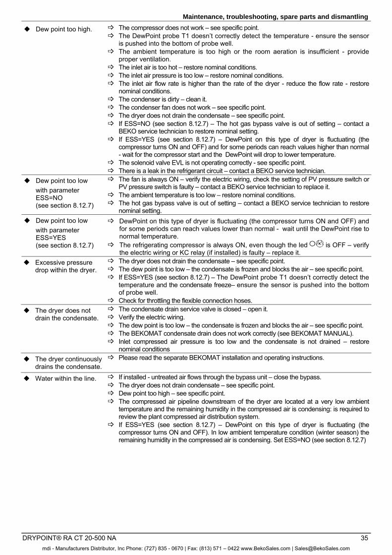
Dew point too high. The compressor does not work – see specific point. The DewPoint probe T1 doesn’t correctly detect the temperature - ensure the sensor
is pushed into the bottom of probe well. The ambient temperature is too high or the room aeration is insufficient - provide
proper ventilation. The inlet air is too hot – restore nominal conditions. The inlet air pressure is too low – restore nominal conditions. The inlet air flow rate is higher than the rate of the dryer - reduce the flow rate - restore
nominal conditions. The condenser is dirty – clean it. The condenser fan does not work – see specific point. The dryer does not drain the condensate – see specific point. If ESS=NO (see section 8.12.7) – The hot gas bypass valve is out of setting – contact a
BEKO service technician to restore nominal setting. If ESS=YES (see section 8.12.7) – DewPoint on this type of dryer is fluctuating (the
compressor turns ON and OFF) and for some periods can reach values higher than normal - wait for the compressor start and the DewPoint will drop to lower temperature.
The solenoid valve EVL is not operating correctly - see specific point. There is a leak in the refrigerant circuit – contact a BEKO service technician.
Dew point too low with parameter ESS=NO (see section 8.12.7)
The fan is always ON – verify the electric wiring, check the setting of PV pressure switch or PV pressure switch is faulty – contact a BEKO service technician to replace it.
The ambient temperature is too low – restore nominal conditions. The hot gas bypass valve is out of setting – contact a BEKO service technician to restore
nominal setting. Dew point too low
with parameter ESS=YES (see section 8.12.7)
DewPoint on this type of dryer is fluctuating (the compressor turns ON and OFF) and for some periods can reach values lower than normal - wait until the DewPoint rise to normal temperature.
The refrigerating compressor is always ON, even though the led is OFF – verify the electric wiring or KC relay (if installed) is faulty – replace it.
Excessive pressure drop within the dryer.
The dryer does not drain the condensate – see specific point. The dew point is too low – the condensate is frozen and blocks the air – see specific point. If ESS=YES (see section 8.12.7) – The DewPoint probe T1 doesn’t correctly detect the
temperature and the condensate freeze– ensure the sensor is pushed into the bottom of probe well.
Check for throttling the flexible connection hoses. The dryer does not
drain the condensate. The condensate drain service valve is closed – open it. Verify the electric wiring. The dew point is too low – the condensate is frozen and blocks the air – see specific point. The BEKOMAT condensate drain does not work correctly (see BEKOMAT MANUAL). Inlet compressed air pressure is too low and the condensate is not drained – restore
nominal conditions The dryer continuously
drains the condensate. Please read the separate BEKOMAT installation and operating instructions.
Water within the line. If installed - untreated air flows through the bypass unit – close the bypass. The dryer does not drain condensate – see specific point. Dew point too high – see specific point. The compressed air pipeline downstream of the dryer are located at a very low ambient
temperature and the remaining humidity in the compressed air is condensing: is required to review the plant compressed air distribution system.
If ESS=YES (see section 8.12.7) – DewPoint on this type of dryer is fluctuating (the compressor turns ON and OFF). In low ambient temperature condition (winter season) the remaining humidity in the compressed air is condensing. Set ESS=NO (see section 8.12.7)
mdi - Manufacturers Distributor, Inc Phone: (727) 835 - 0670 | Fax: (813) 571 – 0422 www.BekoSales.com | [email protected]
Maintenance, troubleshooting, spare parts and dismantling
36 DRYPOINT® RA CT 20-500 NA
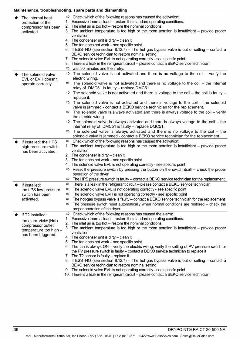
The internal heat protection of the compressor has been activated
Check which of the following reasons has caused the activation: 1. Excessive thermal load – restore the standard operating conditions. 2. The inlet air is too hot – restore the nominal conditions. 3. The ambient temperature is too high or the room aeration is insufficient – provide proper
ventilation. 4. The condenser unit is dirty – clean it. 5. The fan does not work – see specific point. 6. If ESS=NO (see section 8.12.7) – The hot gas bypass valve is out of setting – contact a
BEKO service technician to restore nominal setting. 7. The solenoid valve EVL is not operating correctly - see specific point. 8. There is a leak in the refrigerant circuit – please contact a BEKO service technician. wait 30 minutes and then retry.
The solenoid valve EVL or EVH doesn’t operate correctly
The solenoid valve is not activated and there is no voltage to the coil – verify the electric wiring.
The solenoid valve is not activated and there is no voltage to the coil – the internal relay of DMC51 is faulty – replace DMC51.
The solenoid valve is not activated and there is voltage to the coil – the coil is faulty – replace it.
The solenoid valve is not activated and there is voltage to the coil – the solenoid valve is jammed - contact a BEKO service technician for the replacement.
The solenoid valve is always activated and there is always voltage to the coil – verify the electric wiring
The solenoid valve is always activated and there is always voltage to the coil – the internal relay of DMC51 is faulty – replace DMC51.
The solenoid valve is always activated and there is no voltage to the coil – the solenoid valve is jammed - contact a BEKO service technician for the replacement.
If installed: the HPS high-pressure switch has been activated.
Check which of the following reasons has caused the activation: 1. The ambient temperature is too high or the room aeration is insufficient – provide proper
ventilation. 2. The condenser is dirty – clean it. 3. The fan does not work – see specific point. 4. The solenoid valve EVL is not operating correctly - see specific point Reset the pressure switch by pressing the button on the switch itself – check the proper
operation of the dryer. The HPS pressure switch is faulty – contact a BEKO service technician for the replacement.
If installed: the LPS low-pressure switch has been activated.
There is a leak in the refrigerant circuit – please contact a BEKO service technician. The solenoid valve EVL is not operating correctly - see specific point The solenoid valve EVH is not operating correctly - see specific point The hot-gas bypass valve is faulty – contact a BEKO service technician for the replacement The pressure switch reset automatically when normal conditions are restored – check the
proper operation of the dryer. If T2 installed:
the alarm (Hdt) compressor outlet temperature too high – has been triggered.
Check which of the following reasons has caused the alarm: 1. Excessive thermal load – restore the standard operating conditions. 2. The inlet air is too hot – restore the nominal conditions. 3. The ambient temperature is too high or the room aeration is insufficient – provide proper
ventilation. 4. The condenser unit is dirty – clean it. 5. The fan does not work – see specific point. 6. The fan is always ON – verify the electric wiring, verify the setting of PV pressure switch or
the PV pressure switch is faulty – contact a BEKO service technician to replace it 7. The T2 sensor is faulty – replace it 8. If ESS=NO (see section 8.12.7) – The hot gas bypass valve is out of setting – contact a
BEKO service technician to restore nominal setting. 9. The solenoid valve EVL is not operating correctly - see specific point 10. There is a leak in the refrigerant circuit – please contact a BEKO service technician.
mdi - Manufacturers Distributor, Inc Phone: (727) 835 - 0670 | Fax: (813) 571 – 0422 www.BekoSales.com | [email protected]
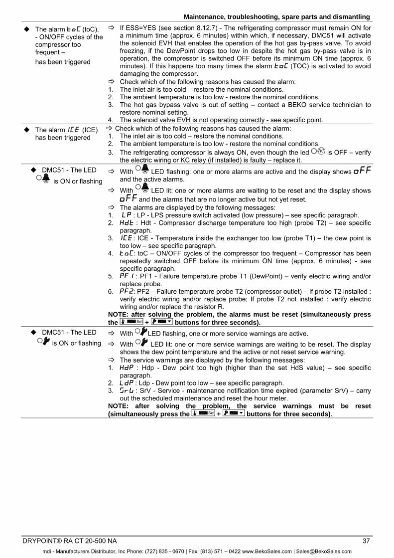
Maintenance, troubleshooting, spare parts and dismantling
DRYPOINT® RA CT 20-500 NA 37
The alarm (toC), - ON/OFF cycles of the compressor too frequent – has been triggered
If ESS=YES (see section 8.12.7) - The refrigerating compressor must remain ON for a minimum time (approx. 6 minutes) within which, if necessary, DMC51 will activate the solenoid EVH that enables the operation of the hot gas by-pass valve. To avoid freezing, if the DewPoint drops too low in despite the hot gas by-pass valve is in operation, the compressor is switched OFF before its minimum ON time (approx. 6 minutes). If this happens too many times the alarm (TOC) is activated to avoid damaging the compressor.
Check which of the following reasons has caused the alarm: 1. The inlet air is too cold – restore the nominal conditions. 2. The ambient temperature is too low - restore the nominal conditions. 3. The hot gas bypass valve is out of setting – contact a BEKO service technician to
restore nominal setting. 4. The solenoid valve EVH is not operating correctly - see specific point.
The alarm (ICE) has been triggered
Check which of the following reasons has caused the alarm: 1. The inlet air is too cold – restore the nominal conditions. 2. The ambient temperature is too low - restore the nominal conditions. 3. The refrigerating compressor is always ON, even though the led is OFF – verify
the electric wiring or KC relay (if installed) is faulty – replace it. DMC51 - The LED
is ON or flashing With LED flashing: one or more alarms are active and the display shows
and the active alarms.
With LED lit: one or more alarms are waiting to be reset and the display shows and the alarms that are no longer active but not yet reset.
The alarms are displayed by the following messages: 1. : LP - LPS pressure switch activated (low pressure) – see specific paragraph. 2. : Hdt - Compressor discharge temperature too high (probe T2) – see specific
paragraph. 3. : ICE - Temperature inside the exchanger too low (probe T1) – the dew point is
too low – see specific paragraph. 4. : toC – ON/OFF cycles of the compressor too frequent – Compressor has been
repeatedly switched OFF before its minimum ON time (approx. 6 minutes) - see specific paragraph.
5. : PF1 - Failure temperature probe T1 (DewPoint) – verify electric wiring and/or replace probe.
6. : PF2 – Failure temperature probe T2 (compressor outlet) – If probe T2 installed : verify electric wiring and/or replace probe; If probe T2 not installed : verify electric wiring and/or replace the resistor R.
NOTE: after solving the problem, the alarms must be reset (simultaneously press the Set + buttons for three seconds).
DMC51 - The LED is ON or flashing
With LED flashing, one or more service warnings are active. With LED lit: one or more service warnings are waiting to be reset. The display
shows the dew point temperature and the active or not reset service warning. The service warnings are displayed by the following messages: 1. : Hdp - Dew point too high (higher than the set HdS value) – see specific
paragraph. 2. : Ldp - Dew point too low – see specific paragraph. 3. : SrV - Service - maintenance notification time expired (parameter SrV) – carry
out the scheduled maintenance and reset the hour meter. NOTE: after solving the problem, the service warnings must be reset (simultaneously press the Set + buttons for three seconds).
mdi - Manufacturers Distributor, Inc Phone: (727) 835 - 0670 | Fax: (813) 571 – 0422 www.BekoSales.com | [email protected]
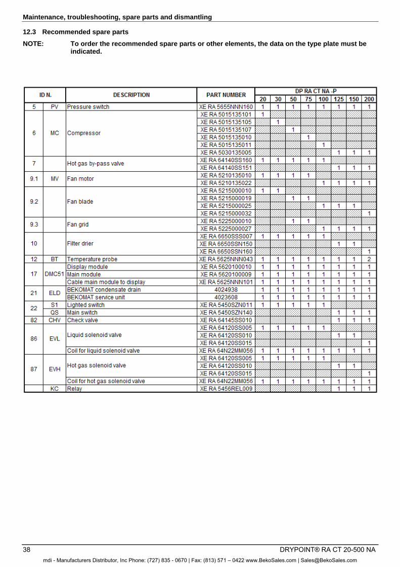
Maintenance, troubleshooting, spare parts and dismantling
38 DRYPOINT® RA CT 20-500 NA
12.3 Recommended spare parts
NOTE: To order the recommended spare parts or other elements, the data on the type plate must be indicated.
mdi - Manufacturers Distributor, Inc Phone: (727) 835 - 0670 | Fax: (813) 571 – 0422 www.BekoSales.com | [email protected]
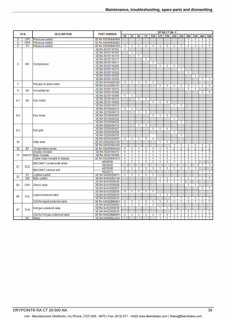
Maintenance, troubleshooting, spare parts and dismantling
DRYPOINT® RA CT 20-500 NA 39
mdi - Manufacturers Distributor, Inc Phone: (727) 835 - 0670 | Fax: (813) 571 – 0422 www.BekoSales.com | [email protected]
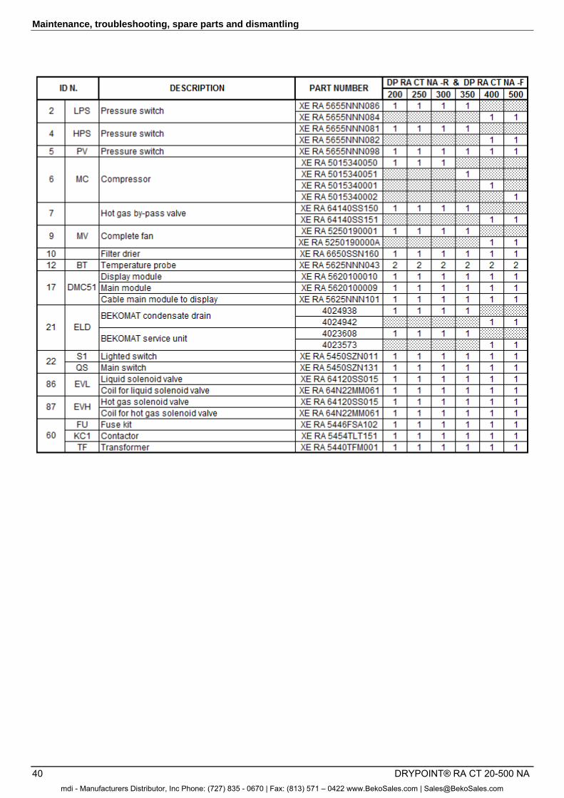
Maintenance, troubleshooting, spare parts and dismantling
40 DRYPOINT® RA CT 20-500 NA
mdi - Manufacturers Distributor, Inc Phone: (727) 835 - 0670 | Fax: (813) 571 – 0422 www.BekoSales.com | [email protected]
Maintenance, troubleshooting, spare parts and dismantling
DRYPOINT® RA CT 20-500 NA 41
12.4 Maintenance works at the refrigeration cycle
Caution!
Refrigerant!
Maintenance and repair works at refrigeration systems must only be carried out by BEKO service technicians in accordance with the local provisions. The total amount of refrigerant in the system must be collected for recycling purposes, resource recovery or disposal. The refrigerant must not be discharged into the environment.
When delivered, the dryer is ready to operate and filled with a refrigerant of the R134a or R407C type.
Should you detect a refrigerant leak, please contact a BEKO service technician. Prior to any intervention, the room needs to be ventilated. When the refrigeration cycle needs to be refilled, please also contact a BEKO service technician. You will find the refrigerant type and amount on the type plate of the dryer.
Properties of the refrigerants used:
Refrigerant Chemical formula MIK GWP
R134a - HFC CH2FCF3 1000 ppm 1300
R407C - HFC R32/125/134a (23/25/52) CHF2CF3/CH2F2/CH2FCF3
1000 ppm 1653
12.5 Dismantling the dryer
When the dryer is dismantled, all parts and operating materials related to the plant need to be disposed of separately.
Component Material
Refrigerant R407C, R134a, oil Roof and supports Structural steel, epoxy paint coat Refrigerating compressor Steel, copper, aluminium, oil Aluminium heat exchanger Aluminium Condenser unit Aluminium, copper, structural steel Pipe Copper Fan Aluminium, copper, steel BEKOMAT condensate drain PVC, aluminium, steel Insulant Synthetic rubber without CFCs, polysterene, polyurethane Electric cable Copper, PVC Electric parts PVC, copper, brass
We recommend observing the safety provisions in force for the disposal of each material type. The refrigerant contains lubricating-oil droplets which are released by the compressor. The refrigerant must not be discharged into the environment. It must to be sucked off from the dryer using a suitable device, and then needs to be supplied to a collection point.
mdi - Manufacturers Distributor, Inc Phone: (727) 835 - 0670 | Fax: (813) 571 – 0422 www.BekoSales.com | [email protected]
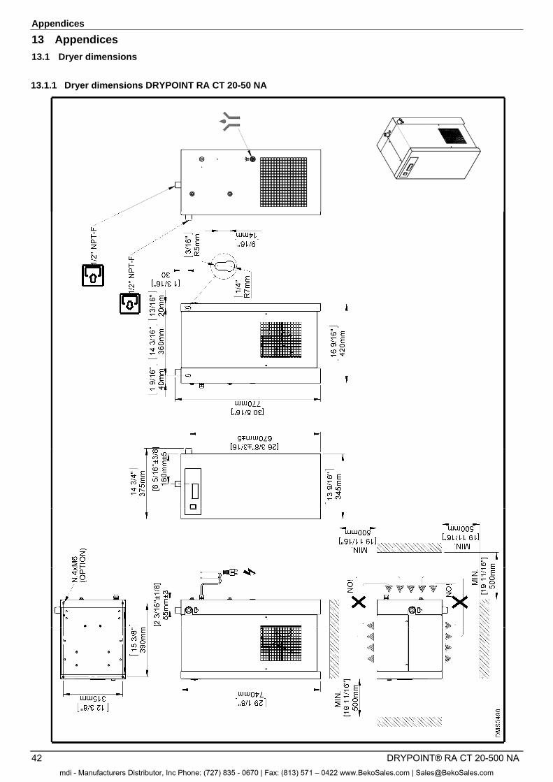
Appendices
42 DRYPOINT® RA CT 20-500 NA
13 Appendices
13.1 Dryer dimensions
13.1.1 Dryer dimensions DRYPOINT RA CT 20-50 NA
mdi - Manufacturers Distributor, Inc Phone: (727) 835 - 0670 | Fax: (813) 571 – 0422 www.BekoSales.com | [email protected]
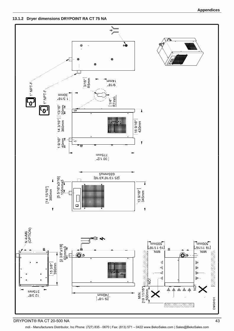
Appendices
DRYPOINT® RA CT 20-500 NA 43
13.1.2 Dryer dimensions DRYPOINT RA CT 75 NA
mdi - Manufacturers Distributor, Inc Phone: (727) 835 - 0670 | Fax: (813) 571 – 0422 www.BekoSales.com | [email protected]
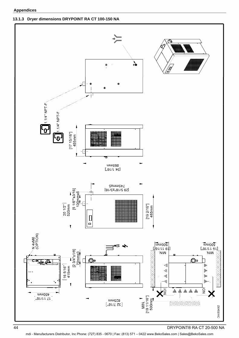
Appendices
44 DRYPOINT® RA CT 20-500 NA
13.1.3 Dryer dimensions DRYPOINT RA CT 100-150 NA
mdi - Manufacturers Distributor, Inc Phone: (727) 835 - 0670 | Fax: (813) 571 – 0422 www.BekoSales.com | [email protected]
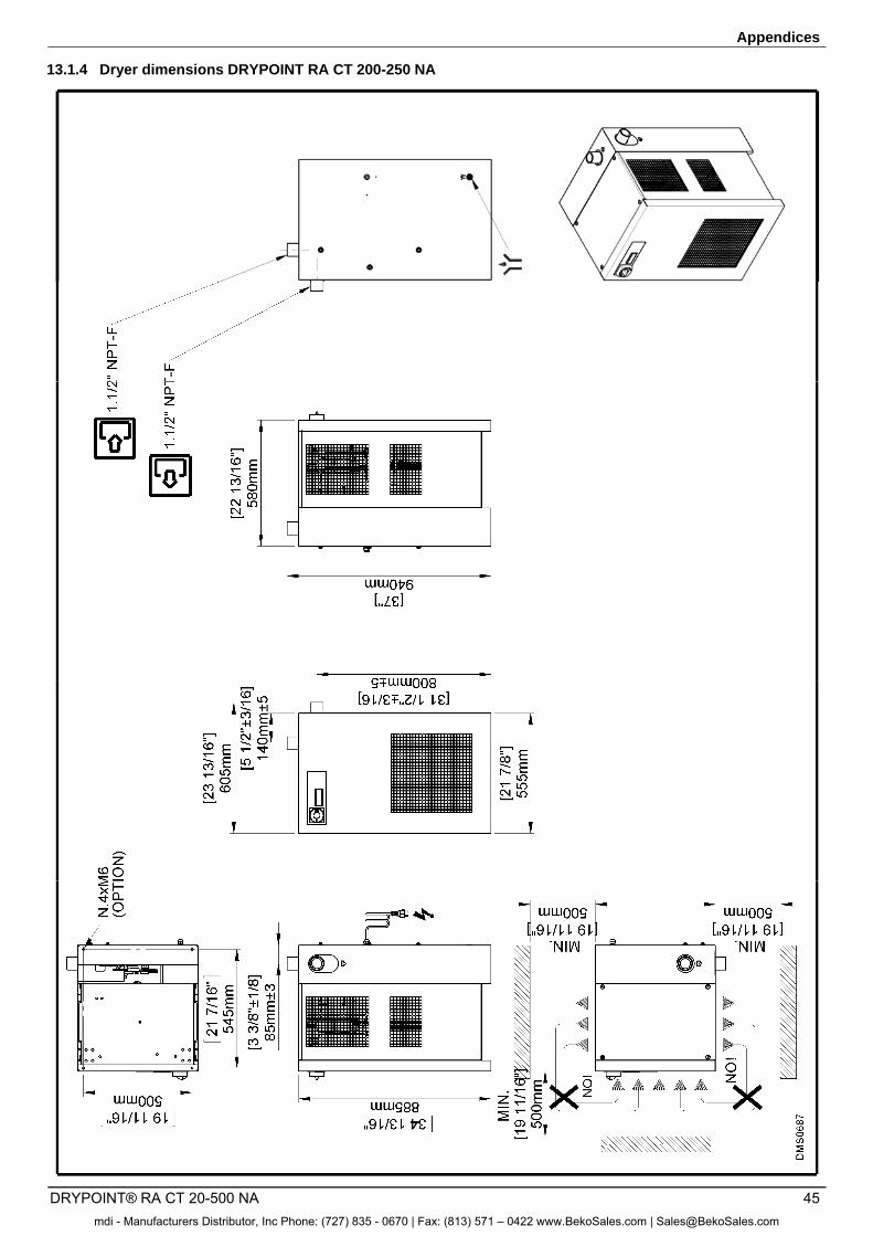
Appendices
DRYPOINT® RA CT 20-500 NA 45
13.1.4 Dryer dimensions DRYPOINT RA CT 200-250 NA
mdi - Manufacturers Distributor, Inc Phone: (727) 835 - 0670 | Fax: (813) 571 – 0422 www.BekoSales.com | [email protected]
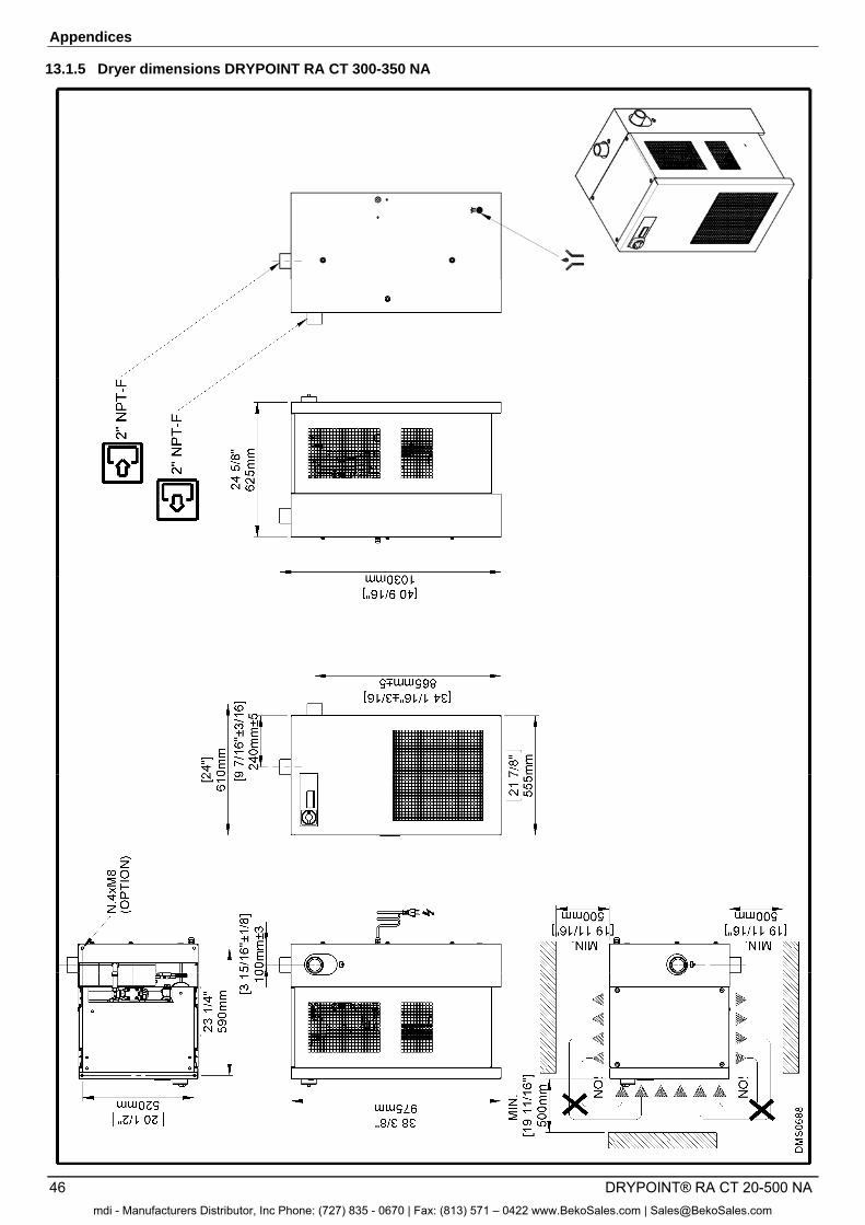
Appendices
46 DRYPOINT® RA CT 20-500 NA
13.1.5 Dryer dimensions DRYPOINT RA CT 300-350 NA
mdi - Manufacturers Distributor, Inc Phone: (727) 835 - 0670 | Fax: (813) 571 – 0422 www.BekoSales.com | [email protected]
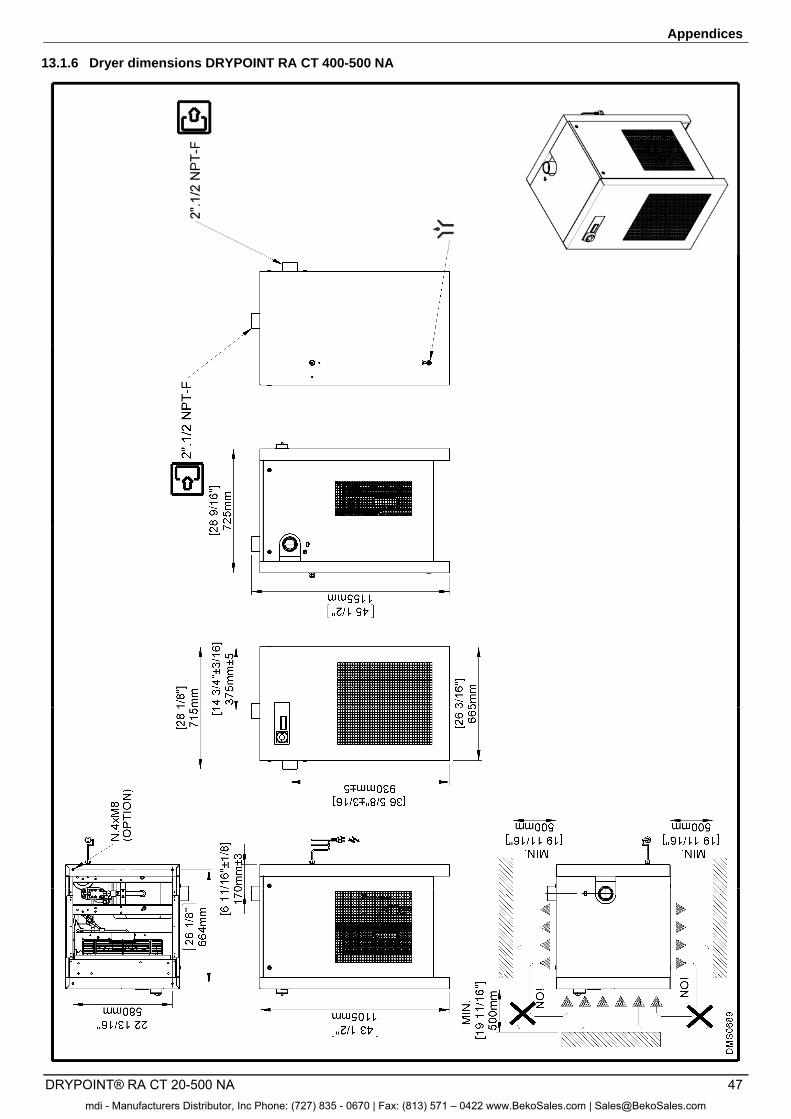
Appendices
DRYPOINT® RA CT 20-500 NA 47
13.1.6 Dryer dimensions DRYPOINT RA CT 400-500 NA
mdi - Manufacturers Distributor, Inc Phone: (727) 835 - 0670 | Fax: (813) 571 – 0422 www.BekoSales.com | [email protected]
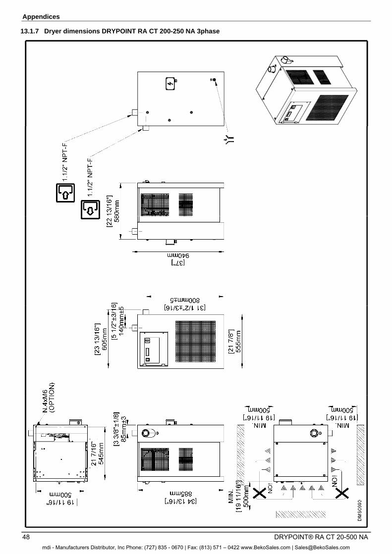
Appendices
48 DRYPOINT® RA CT 20-500 NA
13.1.7 Dryer dimensions DRYPOINT RA CT 200-250 NA 3phase
mdi - Manufacturers Distributor, Inc Phone: (727) 835 - 0670 | Fax: (813) 571 – 0422 www.BekoSales.com | [email protected]
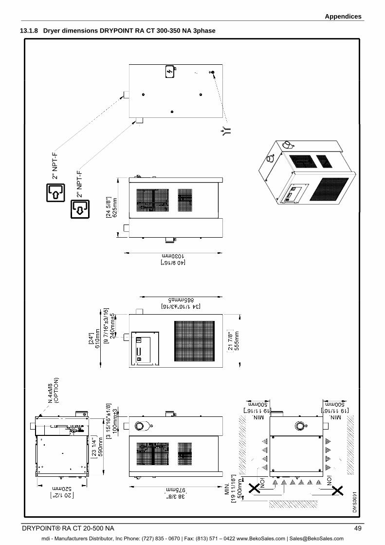
Appendices
DRYPOINT® RA CT 20-500 NA 49
13.1.8 Dryer dimensions DRYPOINT RA CT 300-350 NA 3phase
mdi - Manufacturers Distributor, Inc Phone: (727) 835 - 0670 | Fax: (813) 571 – 0422 www.BekoSales.com | [email protected]
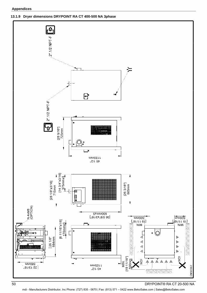
Appendices
50 DRYPOINT® RA CT 20-500 NA
13.1.9 Dryer dimensions DRYPOINT RA CT 400-500 NA 3phase
mdi - Manufacturers Distributor, Inc Phone: (727) 835 - 0670 | Fax: (813) 571 – 0422 www.BekoSales.com | [email protected]
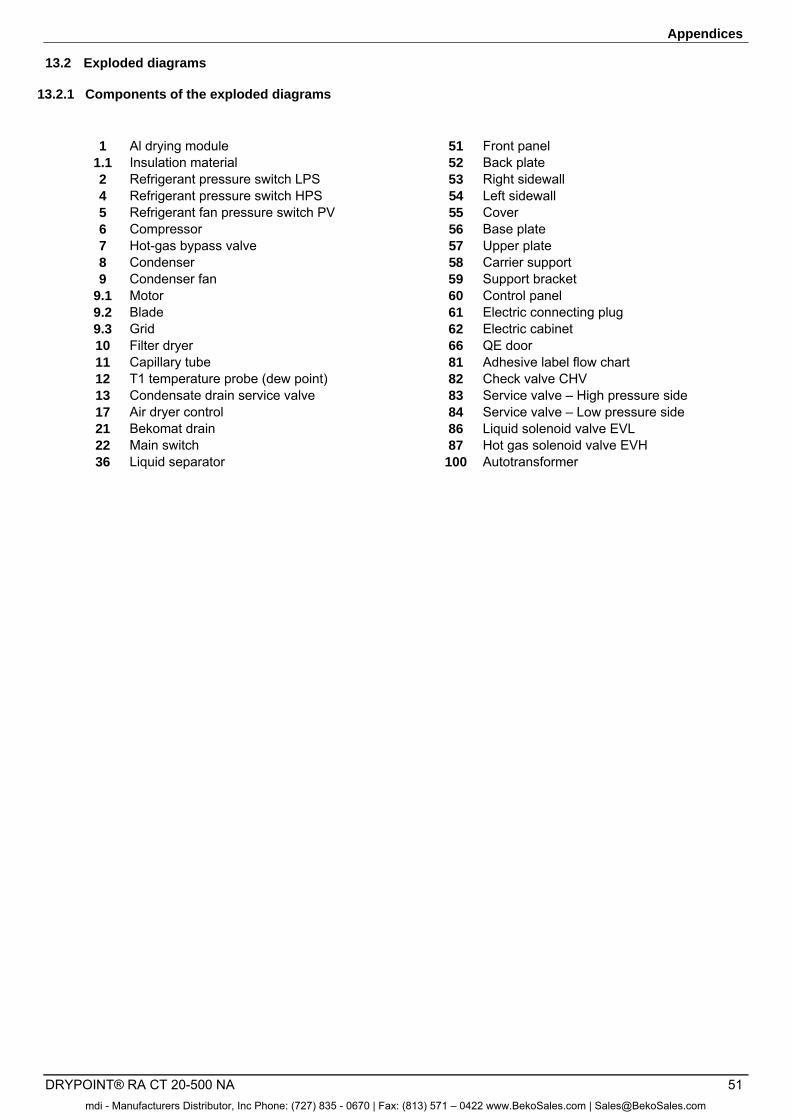
Appendices
DRYPOINT® RA CT 20-500 NA 51
13.2 Exploded diagrams
13.2.1 Components of the exploded diagrams
1 Al drying module 51 Front panel 1.1 Insulation material 52 Back plate 2 Refrigerant pressure switch LPS 53 Right sidewall 4 Refrigerant pressure switch HPS 54 Left sidewall 5 Refrigerant fan pressure switch PV 55 Cover 6 Compressor 56 Base plate 7 Hot-gas bypass valve 57 Upper plate 8 Condenser 58 Carrier support 9 Condenser fan 59 Support bracket 9.1 Motor 60 Control panel 9.2 Blade 61 Electric connecting plug 9.3 Grid 62 Electric cabinet 10 Filter dryer 66 QE door 11 Capillary tube 81 Adhesive label flow chart 12 T1 temperature probe (dew point) 82 Check valve CHV 13 Condensate drain service valve 83 Service valve – High pressure side 17 Air dryer control 84 Service valve – Low pressure side 21 Bekomat drain 86 Liquid solenoid valve EVL 22 Main switch 87 Hot gas solenoid valve EVH 36 Liquid separator 100 Autotransformer
mdi - Manufacturers Distributor, Inc Phone: (727) 835 - 0670 | Fax: (813) 571 – 0422 www.BekoSales.com | [email protected]
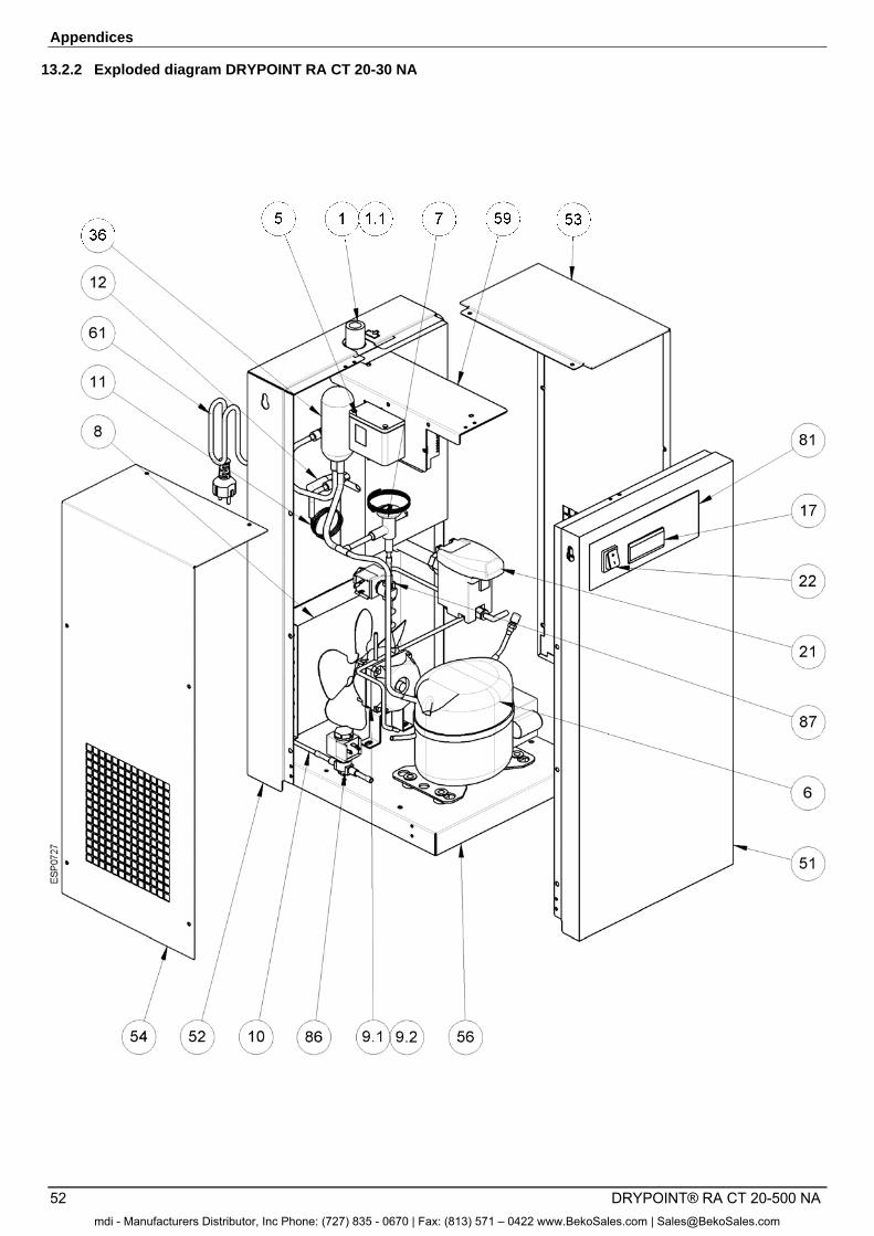
Appendices
52 DRYPOINT® RA CT 20-500 NA
13.2.2 Exploded diagram DRYPOINT RA CT 20-30 NA
mdi - Manufacturers Distributor, Inc Phone: (727) 835 - 0670 | Fax: (813) 571 – 0422 www.BekoSales.com | [email protected]
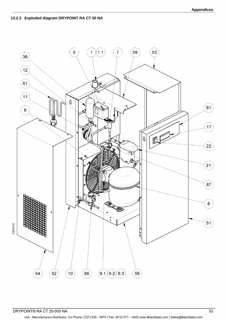
Appendices
DRYPOINT® RA CT 20-500 NA 53
13.2.3 Exploded diagram DRYPOINT RA CT 50 NA
mdi - Manufacturers Distributor, Inc Phone: (727) 835 - 0670 | Fax: (813) 571 – 0422 www.BekoSales.com | [email protected]
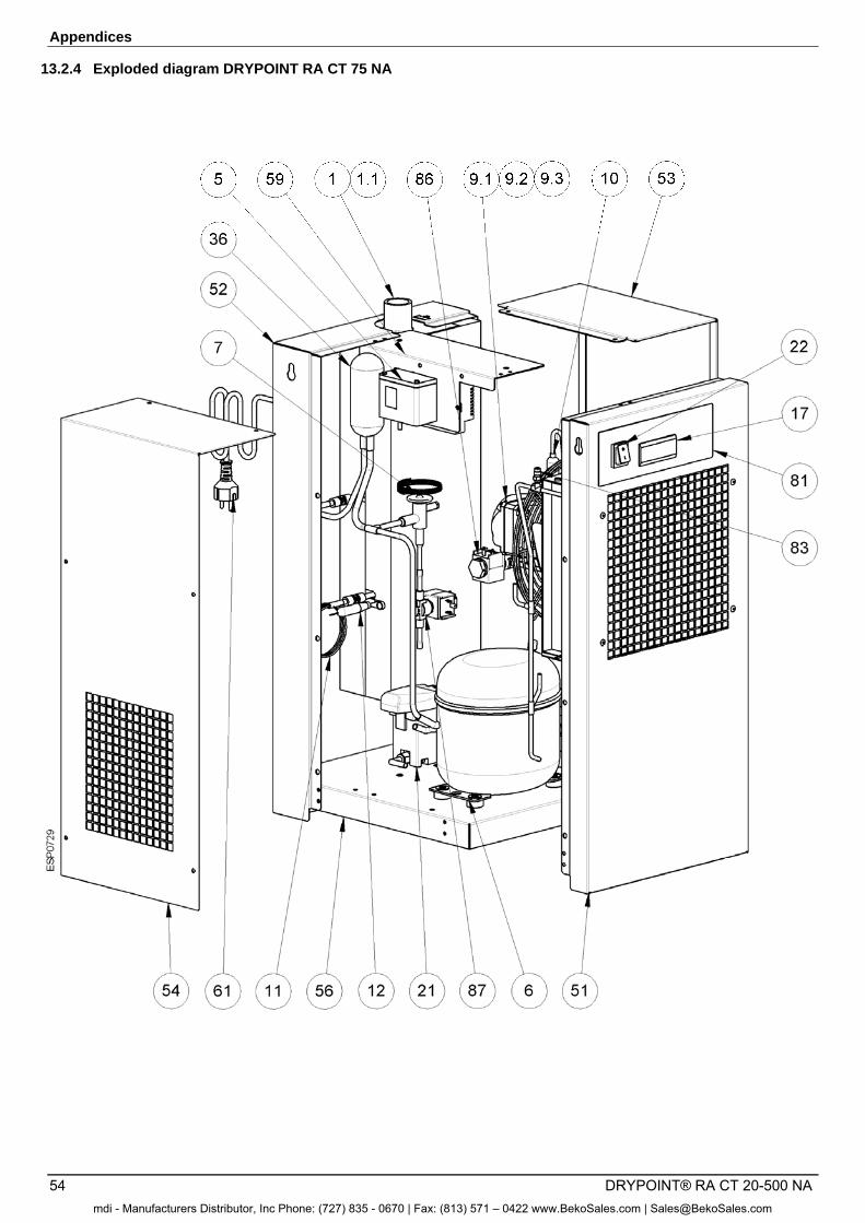
Appendices
54 DRYPOINT® RA CT 20-500 NA
13.2.4 Exploded diagram DRYPOINT RA CT 75 NA
mdi - Manufacturers Distributor, Inc Phone: (727) 835 - 0670 | Fax: (813) 571 – 0422 www.BekoSales.com | [email protected]
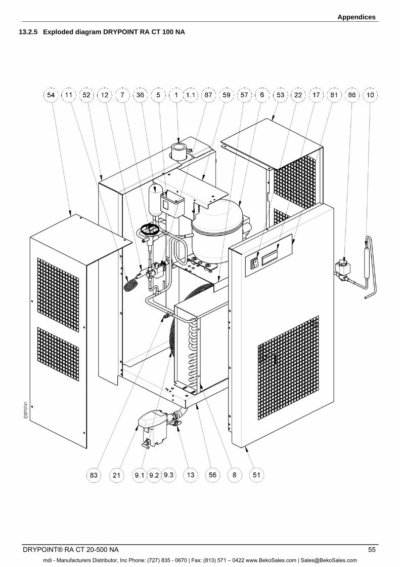
Appendices
DRYPOINT® RA CT 20-500 NA 55
13.2.5 Exploded diagram DRYPOINT RA CT 100 NA
mdi - Manufacturers Distributor, Inc Phone: (727) 835 - 0670 | Fax: (813) 571 – 0422 www.BekoSales.com | [email protected]
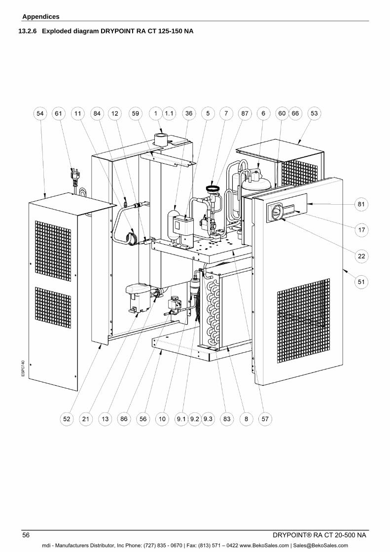
Appendices
56 DRYPOINT® RA CT 20-500 NA
13.2.6 Exploded diagram DRYPOINT RA CT 125-150 NA
mdi - Manufacturers Distributor, Inc Phone: (727) 835 - 0670 | Fax: (813) 571 – 0422 www.BekoSales.com | [email protected]
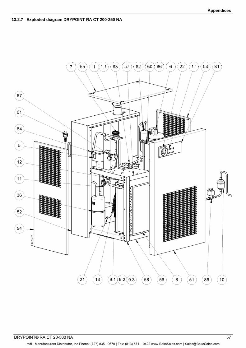
Appendices
DRYPOINT® RA CT 20-500 NA 57
13.2.7 Exploded diagram DRYPOINT RA CT 200-250 NA
mdi - Manufacturers Distributor, Inc Phone: (727) 835 - 0670 | Fax: (813) 571 – 0422 www.BekoSales.com | [email protected]
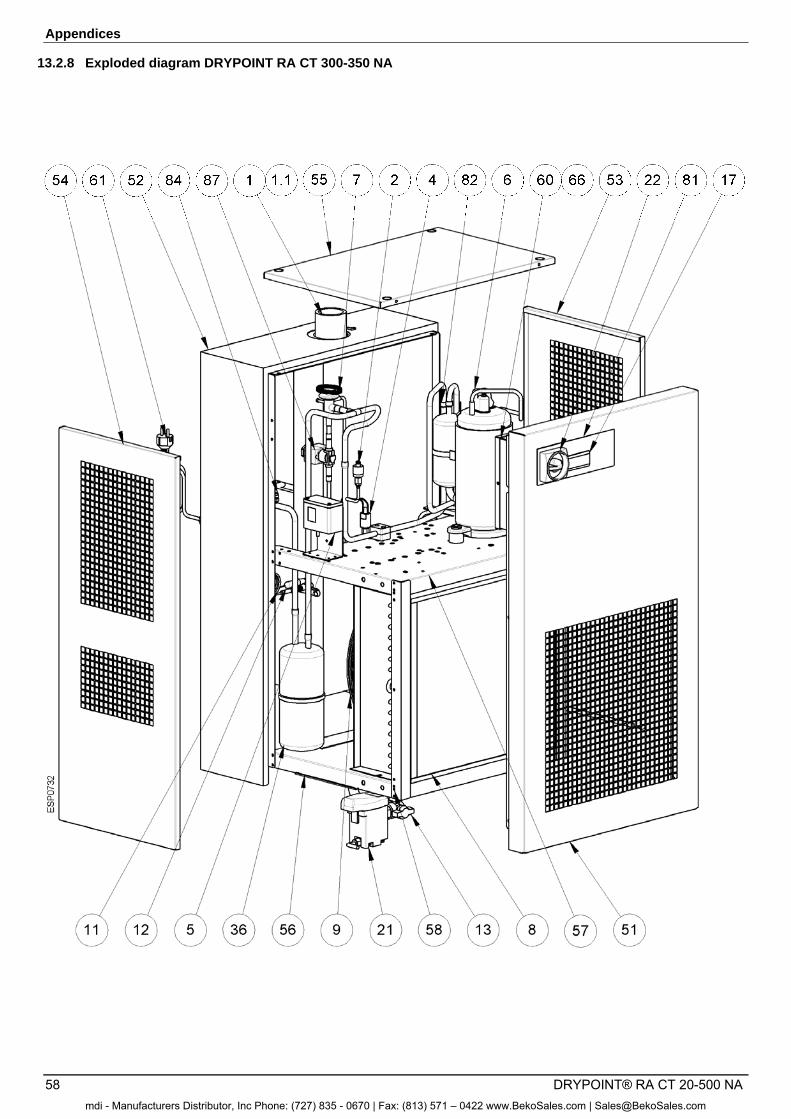
Appendices
58 DRYPOINT® RA CT 20-500 NA
13.2.8 Exploded diagram DRYPOINT RA CT 300-350 NA
mdi - Manufacturers Distributor, Inc Phone: (727) 835 - 0670 | Fax: (813) 571 – 0422 www.BekoSales.com | [email protected]
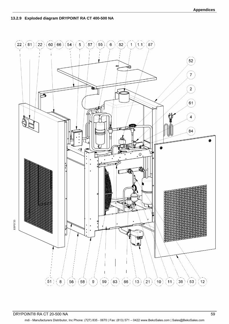
Appendices
DRYPOINT® RA CT 20-500 NA 59
13.2.9 Exploded diagram DRYPOINT RA CT 400-500 NA
mdi - Manufacturers Distributor, Inc Phone: (727) 835 - 0670 | Fax: (813) 571 – 0422 www.BekoSales.com | [email protected]
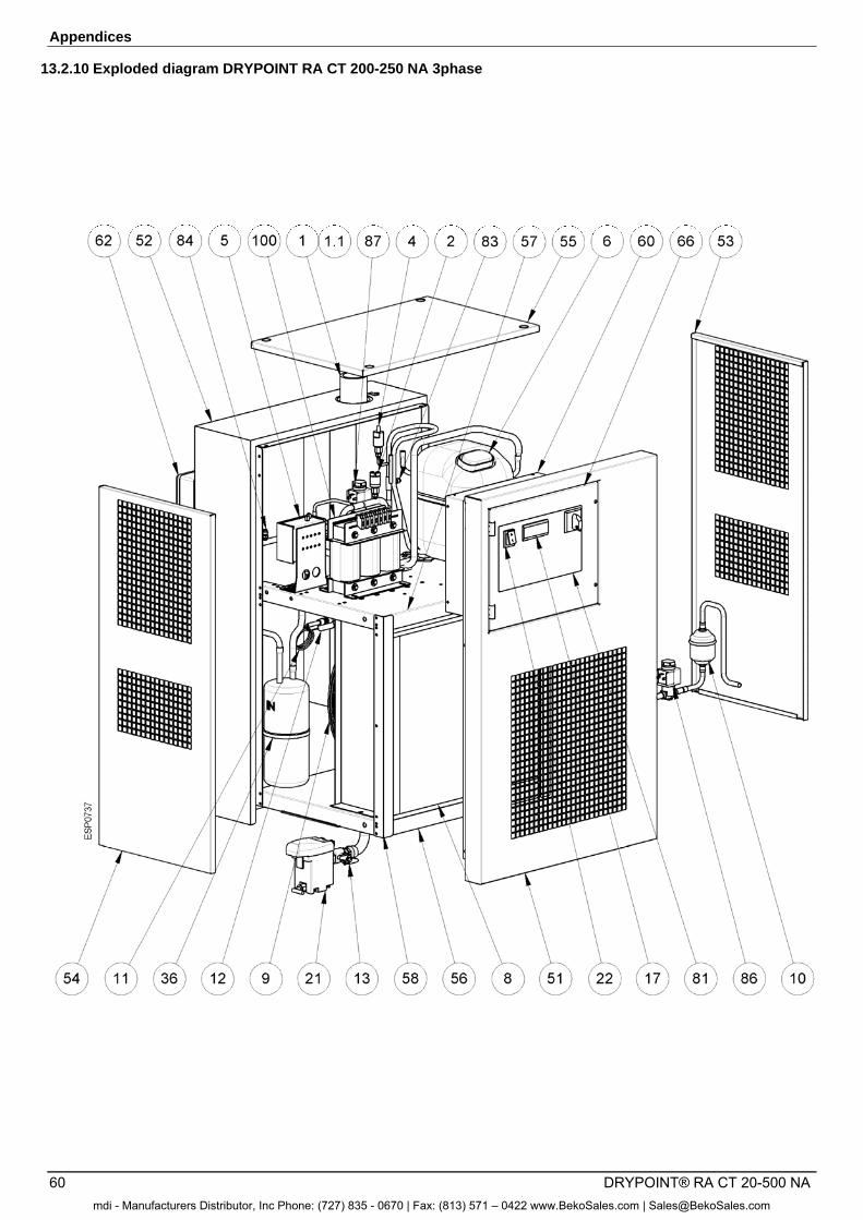
Appendices
60 DRYPOINT® RA CT 20-500 NA
13.2.10 Exploded diagram DRYPOINT RA CT 200-250 NA 3phase
mdi - Manufacturers Distributor, Inc Phone: (727) 835 - 0670 | Fax: (813) 571 – 0422 www.BekoSales.com | [email protected]
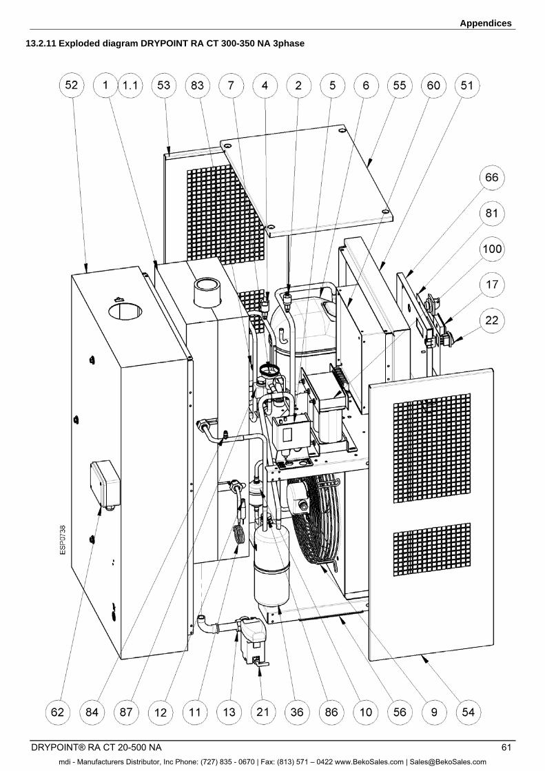
Appendices
DRYPOINT® RA CT 20-500 NA 61
13.2.11 Exploded diagram DRYPOINT RA CT 300-350 NA 3phase
mdi - Manufacturers Distributor, Inc Phone: (727) 835 - 0670 | Fax: (813) 571 – 0422 www.BekoSales.com | [email protected]
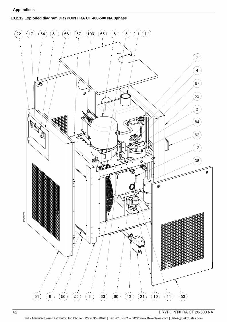
Appendices
62 DRYPOINT® RA CT 20-500 NA
13.2.12 Exploded diagram DRYPOINT RA CT 400-500 NA 3phase
mdi - Manufacturers Distributor, Inc Phone: (727) 835 - 0670 | Fax: (813) 571 – 0422 www.BekoSales.com | [email protected]
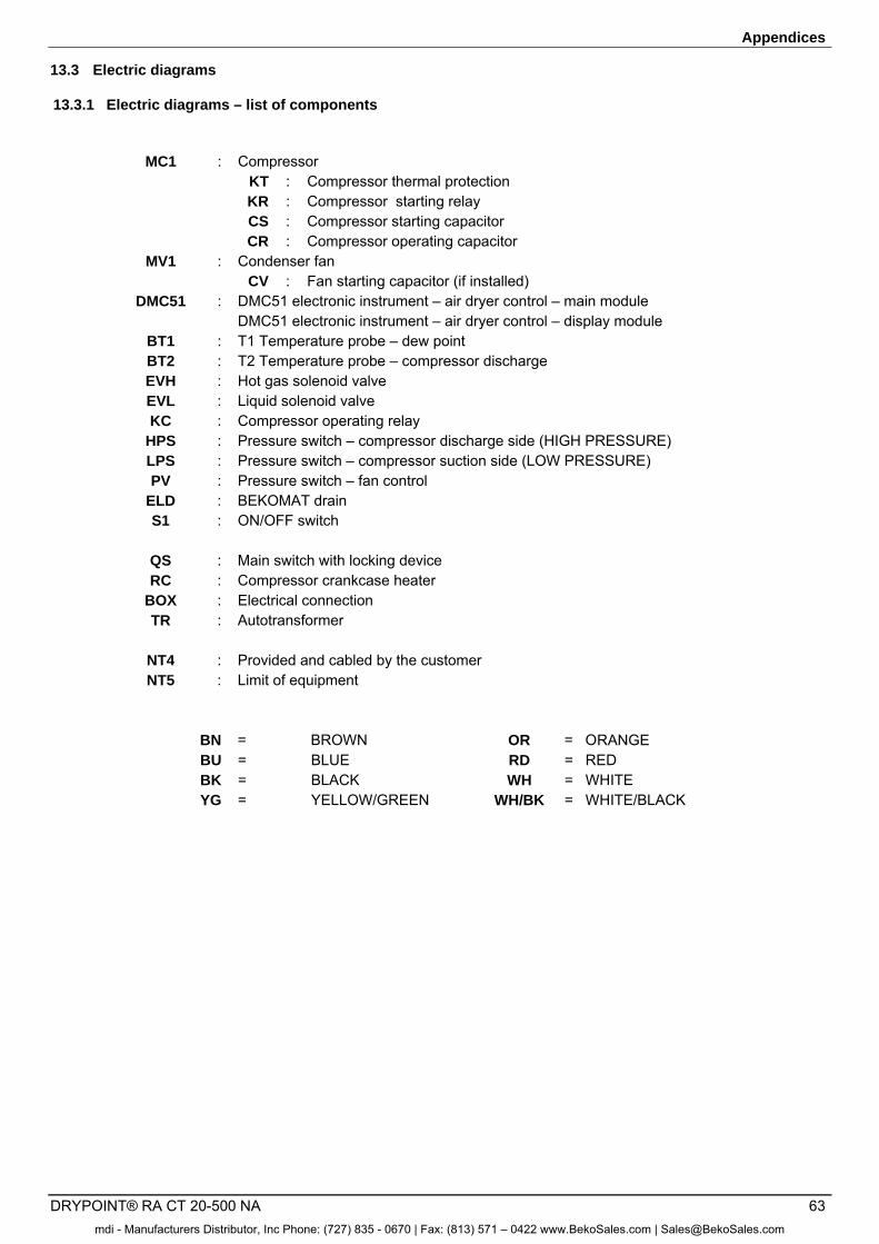
Appendices
DRYPOINT® RA CT 20-500 NA 63
13.3 Electric diagrams
13.3.1 Electric diagrams – list of components
MC1 : Compressor KT : Compressor thermal protection KR : Compressor starting relay CS : Compressor starting capacitor CR : Compressor operating capacitor MV1 : Condenser fan CV : Fan starting capacitor (if installed) DMC51 : DMC51 electronic instrument – air dryer control – main module DMC51 electronic instrument – air dryer control – display module BT1 : T1 Temperature probe – dew point BT2 : T2 Temperature probe – compressor discharge EVH : Hot gas solenoid valve EVL : Liquid solenoid valve KC : Compressor operating relay HPS : Pressure switch – compressor discharge side (HIGH PRESSURE) LPS : Pressure switch – compressor suction side (LOW PRESSURE) PV : Pressure switch – fan control ELD : BEKOMAT drain S1 : ON/OFF switch QS : Main switch with locking device RC : Compressor crankcase heater BOX : Electrical connection TR : Autotransformer NT4 : Provided and cabled by the customer NT5 : Limit of equipment BN = BROWN OR = ORANGE BU = BLUE RD = RED BK = BLACK WH = WHITE YG = YELLOW/GREEN WH/BK = WHITE/BLACK
mdi - Manufacturers Distributor, Inc Phone: (727) 835 - 0670 | Fax: (813) 571 – 0422 www.BekoSales.com | [email protected]
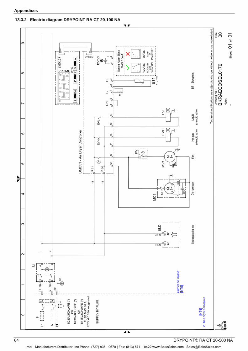
Appendices
64 DRYPOINT® RA CT 20-500 NA
13.3.2 Electric diagram DRYPOINT RA CT 20-100 NA
DM
C51
- Ai
r Dry
er C
ontro
ller
PE
L N
BN
-1
BU
-2
Tech
nica
l mod
ifica
tions
are
sub
ject
to c
hang
e w
ithou
t not
ice;
err
ors
not e
xclu
ded.
01
32
45
67
89
Rev
.
Not
e :
She
et01
of
Dra
win
g no
. :
0100
PE
NL14 1
25
(*) S
ee d
ryer
nam
epla
te
RC
D Id
0.0
3A s
ugge
sted
1/23
0V/5
0Hz+
PE
(*)
FUS
E M
AX
10
A
1/23
0V/6
0Hz+
PE
(*)
OR
SU
PPLY
BY
PLU
G
1/11
5V/6
0Hz+
PE
(*)
OR
EVH
EVL
124
CV
MV
1M 1~
ELD
NTC
10k
BT1
BN-1
BU-2
1314
Set
reset
K
MC
1 KT
M 1~C
CS
KR
RS
13 (N
)
14 (L
)
1216
1115
1017
EVH
EVL
K
78
-+
12VD
C
21
3T2
T15
6LP
S
PV
R
BK
RA
EC
OS
EL0
170
Pow
er O
FF
Ala
rmN
O A
larm
Pow
er O
Nan
dor
MAX
15m
A
0VD
C12
VD
C
X1.
1L/
+X
1.2
N/-
mdi - Manufacturers Distributor, Inc Phone: (727) 835 - 0670 | Fax: (813) 571 – 0422 www.BekoSales.com | [email protected]
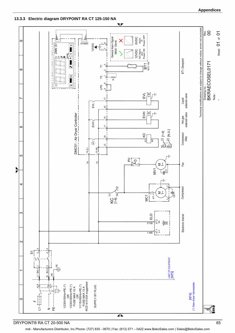
Appendices
DRYPOINT® RA CT 20-500 NA 65
13.3.3 Electric diagram DRYPOINT RA CT 125-150 NA
PE
BN-1
BU-2
Tech
nica
l mod
ifica
tions
are
sub
ject
to c
hang
e w
ithou
t not
ice;
err
ors
not e
xclu
ded.
01
32
45
67
89
Rev
.
Not
e :
She
et01
of
Dra
win
g no
. :
0100
PENL1
(*) S
ee d
ryer
nam
epla
te
RC
D Id
0.0
3A s
ugge
sted
1/23
0V/5
0Hz+
PE
(*)
FUS
E M
AX
13
A
1/23
0V/6
0Hz+
PE
(*)
OR
SU
PP
LY B
Y P
LUG
1/11
5V/6
0Hz+
PE
(*)
OR
ELD
DM
C51
- A
ir D
ryer
Con
trolle
r
13 (N
)
14 (L
)
1216
1115
1017
EVH
EVL
K
EV
HE
VL
KC
KT
S
CR
R
C M 1~
PV
124
CV
MV
1M 1~
KC
[1-6
] 1411
12
[1-4
]12
1114
MC
1
21
35
6LP
SBN-1
BU-2
1314
Set
reset
K
FUS
E M
AX
10
A
BKR
AEC
OSE
L017
1
Pow
er O
FF
Ala
rmN
O A
larm
Pow
er O
Nan
dor
MA
X 15
mA
0VD
C12
VD
C
24 2221
[N.U
.]
A1 A2
NTC
10k
BT1
R
X1.
1L/
+X
1.2
N/-
T2T1
431
22 4
78
-+
12V
DC
mdi - Manufacturers Distributor, Inc Phone: (727) 835 - 0670 | Fax: (813) 571 – 0422 www.BekoSales.com | [email protected]
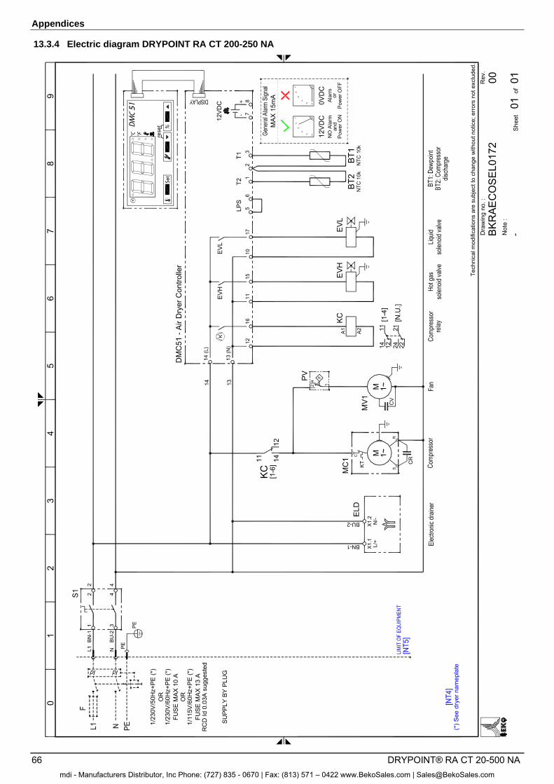
Appendices
66 DRYPOINT® RA CT 20-500 NA
13.3.4 Electric diagram DRYPOINT RA CT 200-250 NA
PE
BN
-1
BU
-2
Tech
nica
l mod
ifica
tions
are
sub
ject
to c
hang
e w
ithou
t not
ice;
err
ors
not e
xclu
ded.
01
32
45
67
89
Rev
.
Not
e :
She
et01
of
Dra
win
g no
. :
0100
PE
NL1
(*) S
ee d
ryer
nam
epla
te
RC
D Id
0.0
3A s
ugge
sted
1/23
0V/5
0Hz+
PE
(*)
FUS
E M
AX
13 A
1/23
0V/6
0Hz+
PE
(*)
OR
SU
PPLY
BY
PLU
G
1/11
5V/6
0Hz+
PE
(*)
OR
431
22 4
ELD
DM
C51
- A
ir D
ryer
Con
trolle
r
13 (N
)
14 (L
)
1216
1115
1017
EVH
EVL
K
EVH
EV
LKC
KT S
CR
R
C M 1~
PV
124
CV
MV1
M 1~
KC [1-6
] 1411
12
MC
1
21
35
6LP
SBN-1
BU-2
1314
Set
reset
K
FUS
E M
AX
10 A
BKR
AEC
OS
EL0
172
Pow
er O
FF
Ala
rmN
O A
larm
Pow
er O
Nan
dor
MAX
15m
A
0VD
C12
VD
C
[1-4
]12
1114 24 22
21[N
.U.]
A1
A2
NTC
10k
NTC
10k
BT2
BT1
X1.
1L/
+X
1.2
N/-
T2T1
78
-+
12VD
C
mdi - Manufacturers Distributor, Inc Phone: (727) 835 - 0670 | Fax: (813) 571 – 0422 www.BekoSales.com | [email protected]
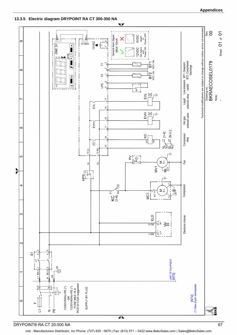
Appendices
DRYPOINT® RA CT 20-500 NA 67
13.3.5 Electric diagram DRYPOINT RA CT 300-350 NA
Tech
nica
l mod
ifica
tions
are
sub
ject
to c
hang
e w
ithou
t not
ice;
err
ors
not e
xclu
ded.
01
32
45
67
89
Rev
.
Not
e :
She
et01
of
Dra
win
g no
. :
0100
(*) S
ee d
ryer
nam
epla
te
ELD
FUS
E M
AX
16
A1/
230V
/60H
z+P
E (*
)
1/23
0V/5
0Hz+
PE
(*)
RC
D Id
0.0
3A s
ugge
sted
OR
Set
reset
K
EV
HE
VL
KC
KT S
CR
R
C M 1~
124
CV
MV
1M 1~
KC
[1-6
] 1411
12
1211
14
MC
1
BN-1
BU-2
1314
13 (N
)
14 (L
)
1216
1115
1017
EV
HE
VL
K
21
35
6LP
S
PV
Pow
er O
FF
Ala
rmN
O A
larm
Pow
er O
Nan
dor
MA
X 1
5mA
0VD
C12
VD
C
PE
BN
-1
BU
-2
PE
NL1
431
22 4
SU
PPLY
BY
PLU
G
[1-4
]24 22
21[N
.U.]
P
HP
S
P
BK
RA
EC
OS
EL0
179
X1.
1L/
+X
1.2
N/-
T2T1
NTC
10k
NTC
10k
BT2
BT1
78
-+
12V
DC
A1
A2
mdi - Manufacturers Distributor, Inc Phone: (727) 835 - 0670 | Fax: (813) 571 – 0422 www.BekoSales.com | [email protected]
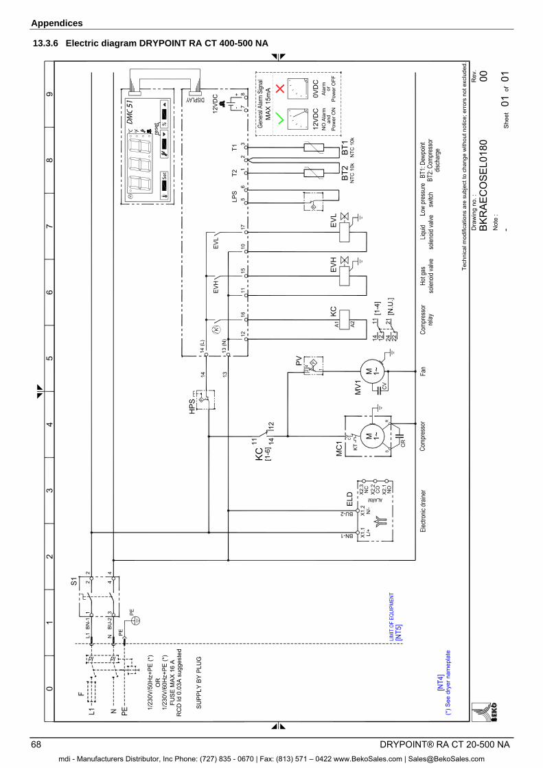
Appendices
68 DRYPOINT® RA CT 20-500 NA
13.3.6 Electric diagram DRYPOINT RA CT 400-500 NA
Tech
nica
l mod
ifica
tions
are
sub
ject
to c
hang
e w
ithou
t not
ice;
err
ors
not e
xclu
ded.
01
32
45
67
89
Rev
.
Not
e :
She
et01
of
Dra
win
g no
. :
0100
(*) S
ee d
ryer
nam
epla
te
FUS
E M
AX
16 A
1/23
0V/6
0Hz+
PE (*
)
1/23
0V/5
0Hz+
PE (*
)
RC
D Id
0.0
3A s
ugge
sted
OR
BN-1
BU-2
ELD
Set
reset
K
EV
HE
VL
KC
KT
S
CR
R
C M 1~
124
CV
MV
1M 1~
KC
[1-6
] 1411
12
1211
14
MC
1
1314
13 (N
)
14 (L
)
1216
1115
1017
EVH
EVL
K
21
35
6LP
S
PV
Pow
er O
FF
Ala
rmN
O A
larm
Pow
er O
Nan
dor
MA
X 15
mA
0VD
C12
VD
C
PE
BN
-1
BU
-2
PE
NL1
431
22 4
SU
PPLY
BY
PLU
G
[1-4
]24 22
21[N
.U.]
P
BK
RA
ECO
SEL0
180
CO
X2.
2N
CX
2.3
NO
X2.
1
X1.
1L/
+X
1.2
N/-
T2T1
NTC
10k
NTC
10k
BT2
BT1
78
-+
12VD
C
A1
A2
P
HP
S
mdi - Manufacturers Distributor, Inc Phone: (727) 835 - 0670 | Fax: (813) 571 – 0422 www.BekoSales.com | [email protected]
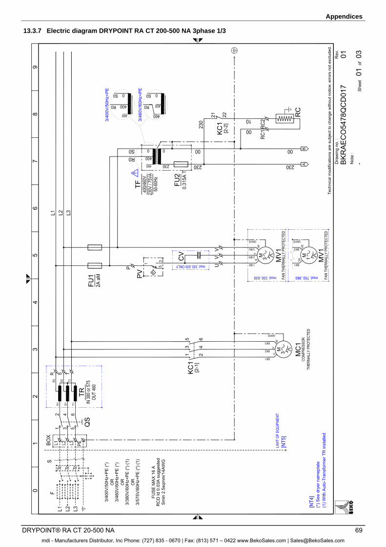
Appendices
DRYPOINT® RA CT 20-500 NA 69
13.3.7 Electric diagram DRYPOINT RA CT 200-500 NA 3phase 1/3 0
13
24
56
78
9
KC
1[2
-1]
21
46
35
W
MC
1
M 3UV
Rev
.
Not
e :
She
et01
of
Dra
win
g no
. :
0301
AB
RC
KC1
[2-2
]
FU2
TF
21 22
PV P
FU1
3/40
0V/5
0Hz+
PE
3/46
0V/6
0Hz+
PE
Tech
nica
l mod
ifica
tions
are
sub
ject
to c
hang
e w
ithou
t not
ice;
err
ors
not e
xclu
ded.
CV M 3
TS
TP
MV1
MV1
TPU
2
1M
3/40
0V/5
0Hz+
PE
(*)
OR
3/46
0V/6
0Hz+
PE
(*)
OR
3/38
0V/6
0Hz+
PE (*
) (1)
OR
3/57
5V/6
0Hz+
PE (*
) (1)
FUS
E M
AX
16
AR
CD
Id 0
.03A
sug
gest
edS
min
2.5
sqm
m/1
4AW
G
TR
(*) S
ee d
ryer
nam
epla
te(1
) With
Aut
o-Tr
ansf
orm
er T
R in
stal
led
BK
RA
EC
O54
78Q
CD
017
mdi - Manufacturers Distributor, Inc Phone: (727) 835 - 0670 | Fax: (813) 571 – 0422 www.BekoSales.com | [email protected]
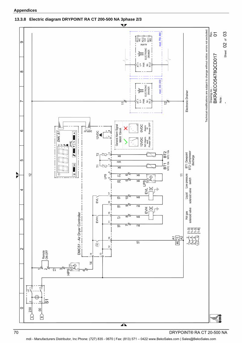
Appendices
70 DRYPOINT® RA CT 20-500 NA
13.3.8 Electric diagram DRYPOINT RA CT 200-500 NA 3phase 2/3 0
13
24
56
78
9
Rev
.
Not
e :
She
et02
of
Dra
win
g no
. :
0301
Tech
nica
l mod
ifica
tions
are
sub
ject
to c
hang
e w
ithou
t not
ice;
err
ors
not e
xclu
ded.
A B
S152
41
Set
reset
K
DM
C51
- A
ir D
ryer
Con
trolle
r
1314
1216
1115
1017
EVH
EV
LK
78
-+
12V
DC
21
3
T1T2
56
LPS
EV
H
NTC
10k
NTC
10k
BT1
BT2
42 1
42
1
HP
S
BK
WH
BK
LPS
A1
A2
KC
1
12
[1-3
]
115126
34
[1-8
]
[1-3
][1
-3]
EV
L
BU
BN
BU
BN
BK
BK
X1.
2
X1.
1
N/-
L/+
X1.
2
X1.
1
N/-
L/+
CO
X2.
2N
CX
2.3
NO
X2.
1P
ower
OFF
Ala
rmN
O A
larm
Pow
er O
Nan
dor
MA
X 15
mA
0VD
C12
VD
C
BK
RA
EC
O54
78Q
CD
017
mdi - Manufacturers Distributor, Inc Phone: (727) 835 - 0670 | Fax: (813) 571 – 0422 www.BekoSales.com | [email protected]
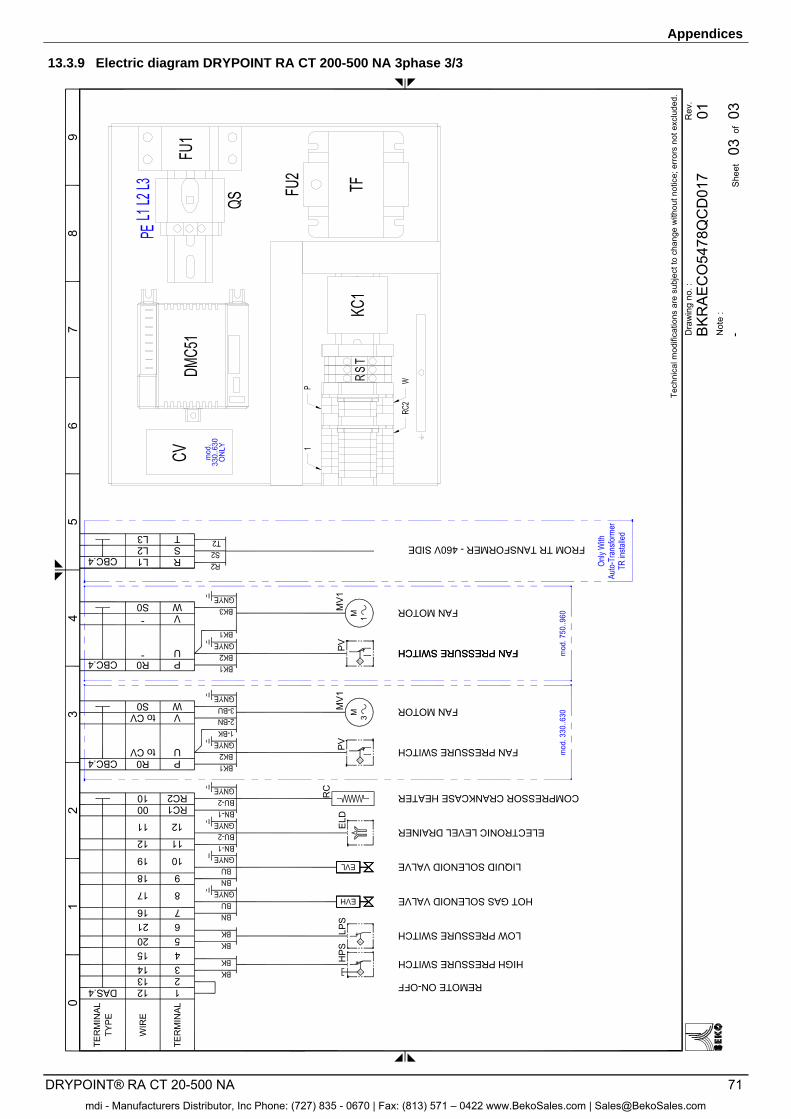
Appendices
DRYPOINT® RA CT 20-500 NA 71
13.3.9 Electric diagram DRYPOINT RA CT 200-500 NA 3phase 3/3 0
13
24
56
78
9
Rev
.
Not
e :
She
et03
of
Dra
win
g no
. :
0301
TER
MIN
AL
COMPRESSOR CRANKCASE HEATER
3
RC
TER
MIN
ALTY
PE
WIR
E14 HIGH PRESSURE SWITCH
LOW PRESSURE SWITCH
4520
HP
SLP
S
15
RC2RC100
10
716621
817
918
1019
1112
1211 ELECTRONIC LEVEL DRAINERELD
LIQUID SOLENOID VALVE
HOT GAS SOLENOID VALVE
Tech
nica
l mod
ifica
tions
are
sub
ject
to c
hang
e w
ithou
t not
ice;
err
ors
not e
xclu
ded.
112DAS.4213 REMOTE ON-OFF
PU
R0to CV
VW
to CVS0
CBC.4P
VM 3
MV
1
FAN PRESSURE SWITCH
FAN MOTOR
FAN PRESSURE SWITCH
FAN MOTOR
PV
M 1
MV
1
-R0
UPCBC.4
S0-
WV
FAN PRESSURE SWITCH
BK
RA
EC
O54
78Q
CD
017
SRL1CBC.4
TL2L3
FROM TR TANSFORMER - 460V SIDE
mdi - Manufacturers Distributor, Inc Phone: (727) 835 - 0670 | Fax: (813) 571 – 0422 www.BekoSales.com | [email protected]

Appendices
72 DRYPOINT® RA CT 20-500 NA
mdi - Manufacturers Distributor, Inc Phone: (727) 835 - 0670 | Fax: (813) 571 – 0422 www.BekoSales.com | [email protected]
Appendices
DRYPOINT® RA CT 20-500 NA 73
mdi - Manufacturers Distributor, Inc Phone: (727) 835 - 0670 | Fax: (813) 571 – 0422 www.BekoSales.com | [email protected]
Appendices
74 DRYPOINT® RA CT 20-500 NA
mdi - Manufacturers Distributor, Inc Phone: (727) 835 - 0670 | Fax: (813) 571 – 0422 www.BekoSales.com | [email protected]
DRYPOINT® RA CT 20-500 NA 75
A
Advice, safety instructions .................................... 5 Appendices ......................................................... 42
B
BEKOMAT .......................................................... 20
C
Capillary tube ...................................................... 16 Certified skilled personnel .............................. 8; 33 Circuit diagram ....................................... 64; 65; 66 Circuit diagrams .................................................. 63 Condensate drain ............................................... 25 Condenser .......................................................... 16 Connection to the compressed-air system ......... 24 Contaminated intake air ...................................... 22 Control panel ...................................................... 13 Correction factors ............................................... 23
D
Danger compressed air .................. 8; 9; 32; 33; 34 Danger supply voltage .............................. 8; 32; 33 Dismantling ......................................................... 32 Dismantling the dryer .......................................... 41 Dryer dimensions .................. 42; 43; 44; 45; 47; 48
E
Electrical connections ......................................... 25 Exclusion from a field of application ................... 11 Exclusion of a field of application ....................... 11 Exploded diagram .... 51; 52; 53; 54; 55; 56; 57; 58
F
Field of application .............................................. 11 Filter dryer........................................................... 16 Flow chart ........................................................... 15 Functional description ......................................... 14
H
Heat exchanger .................................................. 16
Hot-gas bypass valve ......................................... 17
I
Initial start-up ...................................................... 26 Installation ........................................................... 21 Installation plan ................................................... 22
M
Maintenance ....................................................... 32 Maintenance works at the refrigeration cycle ..... 41 Minimum installation requirements ..................... 21
O
Overview of the safety instructions ....................... 8
P
Place of installation ............................................. 21 Pressure Equipment Directive ............................ 11 Proper use .......................................................... 11
R
Recommended spare parts ................................ 38 Refrigerating compressor ................................... 16 Removal from service ......................................... 27 Restart ................................................................ 27
S
Safety instructions ............................................ 5; 8 Safety pictograms in accordance with DIN 4844 .. 6 Spare parts ................................................... 32; 38 Start-up ............................................................... 26 Storage ............................................................... 12
T
Technical data ................................. 28; 29; 30; 31 Technical description .......................................... 13 Transport............................................................. 12 Troubleshooting .................................................. 32 Type plate ............................................................. 5
U
Unauthorised intervention ................................... 10
mdi - Manufacturers Distributor, Inc Phone: (727) 835 - 0670 | Fax: (813) 571 – 0422 www.BekoSales.com | [email protected]

Original operating instructions in English. Subject to technical changes / errors excepted. DRYPOINT_RACT_20-500_NA_manual_en_2014_09
7425MUM281_EN_2014-09
mdi - Manufacturers Distributor, Inc Phone: (727) 835 - 0670 | Fax: (813) 571 – 0422 www.BekoSales.com | [email protected]