Embed Size (px)
Citation preview
INSTRUCTIONS
BX46CLINICAL MICROSCOPE
This instruction manual is for the Olympus Clinical Microscope Model BX46.To ensure the safety, obtain optimum performance and to familiarize yourself fully with the use of this microscope, we recommend that you study this manual thoroughly before operating the microscope.Retain this instruction manual in an easily accessible place near the work desk for future reference.
A X 7 8 5 3
In accordance with European Directive 2002/96/EC on Waste Electrical and Electronic Equipment,
this symbol indicates that the product must not be disposed of as unsorted municipal waste, but
should be collected separately.
Refer to your local Olympus distributor in EU for return and/or collection systems available in your
country.
NOTE: This equipment has been tested and found to comply with the limits for a Class A digital device,
pursuant to Part 15 of the FCC Rules. These limits are designed to provide reasonable protection
against harmful interference when the equipment is operated in a commercial environment. This
equipment generates, uses, and can radiate radio frequency energy and, if not installed and used in
accordance with the instruction manual, may cause harmful interference to radio communications.
Operation of this equipment in a residential area is likely to cause harmful interference in which case
the user will be required to correct the interference at his own expense.
FCC WARNING: Changes or modifications not expressly approved by the party responsible for compliance
could void the user 's authority to operate the equipment.

BX46
CONTENTSCorrect assembly and adjustments are critical for the microscope to exhibit its full performance. If you are going to assemble the microscope yourself, please read section 10, “ASSEMBLY" (pages 31 to 34) carefully.
IMPORTANT -- Be sure to read this section for safe use of the equipment. -- 1-3
13-23
4
5-7
8,9
10-12
1 MODULE NOMENCLATURE
2 CONTROLS
3 FLOW OF OBSERVATION
4 SIMPLIFIED OBSERVATION PROCEDURE
4-1 Basic Operation (Until Observation of Specimen) ........................................................................10,11
4-2 Microscope Adjustments (How to Improve the Observed Image) ........................11,12
1 Adjusting the Interpupillary Distance .................................................................................11
2 Adjusting the Diopter ..........................................11
3 Adjusting the Centering ..................................12 4 Adjusting the Contrast ......................................12
5 USING THE CONTROLS
5-1 Base .................................................................................................................................................................................................................13,14
1 Adjusting the Brightness ...............................13 2 Setting the LIM Brightness ..........................13
3 Using the Filters ..........................................................14
5-2 Focusing Block ................................................................................................................................................................................15,16
1 Focusing Controls ..................................................15 2 Adjusting the Focus .............................................15
3 Replacing the Fine Adjustment Knob ............................................................................................16
4 Adjusting the Coarse Adjustment Knob Tension..................................................................16
5 Pre-focusing Lever ..................................................16
5-3 Stage................................................................................................................................................................................................................17,18
1 Placing the Specimen .......................................17 2 Adjusting the X- and Y-Axis Knob Tension ...................................................................................18
3 Rotating the Stage .................................................18
5-4 Observation Tube .................................................................................................................................................................... 19-22
1 Adjusting the Diopter ..........................................19 2 Using the Eye Shades .......................................19
3 Using the Eyepiece Micrometer Disk ............................................................................................ 20
4 Selecting the Light Path of the Trinocular Tube ......................................................... 20
5 Adjusting the Tilt ..................................................... 21 6 Using Eyepieces Incorporating a Micrometer ...................................................................... 22
5-5 Condenser ................................................................................................................................................................................................... 22
5-6 Immersion Objectives ................................................................................................................................................................. 23
6 CAMERA RECORDING
7 TROUBLESHOOTING GUIDE
8 SPECIFICATIONS
9 OPTICAL CHARACTERISTICS (UIS2 Series)
10 ASSEMBLY -- See this section for the replacement of the light bulb. --
11 HALOGEN LAMP SOCKET INSPECTION SHEET
24
25-27
28,29
30
31-34
35
n PROPER SELECTION OF THE POWER SUPPLY CORD .......................................................... 36,37

1
BX46
SAFETY PRECAUTIONS (Fig. 1)
IMPORTANT
1. If potentially infectious samples may be observed, use protective gloves or other protective means to prevent the skin from contacting with samples directly.
After observation, be sure to clean the portion contacted with samples. · Moving this product is accompanied with the risk of dropping the
samples. Be sure to remove the samples before moving this product. · In case the samples is damaged by erroneous operation, promptly
take the infection prevention measures. · Follow the procedures described in Chapter “Getting Ready” (see on
page 2) prior to using the accessories of this product. Otherwise, the stability of the device will be lost and the dropped samples will cause the possibility of infection.
· When you maintain the device which may have contacted with potentially infectious reagents, be sure to wear the protectors such as gloves, or clean the device prior to operation.
· Before disposing of device contacted with potentially infectious samples, be sure to follow the regulations and rules of your local government.
2. Install the microscope on a sturdy, level table or bench.3. Be careful not to tilt the microscope too much. Otherwise, the mobile
parts such as the light path selector knob may move in unintended directions.
4. Always use the power cord provided by Olympus. If no power cord is provided, please select the proper power cord by referring to the section “PROPER SELECTION OF THE POWER SUPPLY CORD” at the end of this instruction manual.
If the proper power cord is not used, product safety performance cannot be warranted.
5. Always ensure that the grounding terminal of the microscope and that of the wall outlet are properly connected. If the equipment is not grounded, Olympus can no longer warrant the electrical safety performance of the equipment.
Fig. 1
Operation Using the LED Lamp
Safety Note on LED (Light Emitting Diode)
The LED incorporated in the LED lamp housing is a class 1 LED product. The light emitted by LED is basically safe, but do not look at the illumination light directly for an extended period to prevent your eye from being injured
CLASS 1 LED PRODUCT
Operation Using the Halogen Bulb
1. To avoid potential shock hazards and burns when replacing the halogen bulb, set the main switch of the TL4 power supply unit to “ ” (OFF) and allow the lamp socket @ and bulb to cool before touching them.
Designated bulb 6V30WHAL (PHILIPS 5761)
Always use the designated lamp bulb. Using other bulb may cause malfunction.
2. If the lamp cable or power cord comes in contact with the lamp socket or its surroundings, the cable or cord may be melted by the heat, causing an electric shock or fire hazard. To prevent this, distribute the lamp cable and power cord at enough distances from the lamp socket.
3. The standard service life of the lamp socket is eight (8) years of use or 20,000 hours of total power ON period, whichever is the shorter period.
For details, see Inspection Sheet on page 35.
1CAUTION
2
Safety Symbols
The following symbols are found on the microscope. Study the meaning of the symbols and always use the equipment in the safest possible manner.
Symbol Explanation
Indicates that the surface becomes hot, and should not be touched with bare hands.
Indicates a non-specific general hazard. Follow the description given after this symbol or in instruction manual.
Indicates that the main switch is ON.
Indicates that the main switch is OFF.
Caution engraving/label
Caution engraving and label are placed at parts where special precaution is required when handling and using the microscope. Always heed the cautions.
Caution engraving position
Halogen lamp socket[Caution against high temperature]
Caution label position
Rear panel[Caution against high temperature]
If a caution engraving or label is dirty or peeled off, contact Olympus for the replacement or other inquiry.
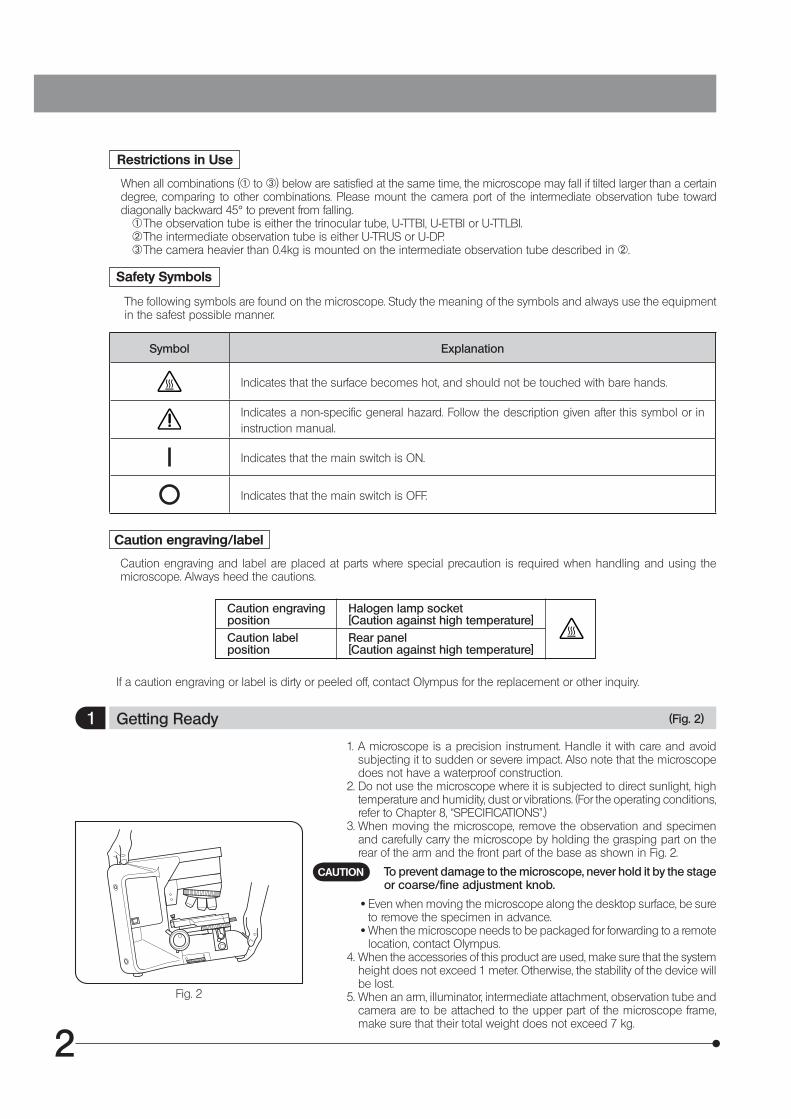
1 Getting Ready (Fig. 2)
1. A microscope is a precision instrument. Handle it with care and avoid subjecting it to sudden or severe impact. Also note that the microscope does not have a waterproof construction.
2. Do not use the microscope where it is subjected to direct sunlight, high temperature and humidity, dust or vibrations. (For the operating conditions, refer to Chapter 8, “SPECIFICATIONS”.)
3. When moving the microscope, remove the observation and specimen and carefully carry the microscope by holding the grasping part on the rear of the arm and the front part of the base as shown in Fig. 2.
To prevent damage to the microscope, never hold it by the stage or coarse/fine adjustment knob.
· Even when moving the microscope along the desktop surface, be sure to remove the specimen in advance.
· When the microscope needs to be packaged for forwarding to a remote location, contact Olympus.
4. When the accessories of this product are used, make sure that the system height does not exceed 1 meter. Otherwise, the stability of the device will be lost.
5. When an arm, illuminator, intermediate attachment, observation tube and camera are to be attached to the upper part of the microscope frame, make sure that their total weight does not exceed 7 kg.
Fig. 2
CAUTION
Restrictions in Use
When all combinations (@ to ³) below are satisfied at the same time, the microscope may fall if tilted larger than a certain degree, comparing to other combinations. Please mount the camera port of the intermediate observation tube toward diagonally backward 45° to prevent from falling.
@ The observation tube is either the trinocular tube, U-TTBI, U-ETBI or U-TTLBI.² The intermediate observation tube is either U-TRUS or U-DP.³ The camera heavier than 0.4kg is mounted on the intermediate observation tube described in ².

3
BX46
2 Maintenance and Storage
1. To clean the lenses and other glass components, simply blow dirt away using a commercially available blower and wipe gently using a piece of cleaning paper (or clean gauze).
If a lens is stained with fingerprints or oil smudges, wipe it gauze slightly moistened with commercially available absolute alcohol.
· Since the absolute alcohol is highly flammable, it must be handled carefully. Be sure to keep it away from open flames or potential sources of electrical sparks --- for example, electrical
equipment that is being switched on or off, which could cause ignition of a fire. Also remember to always use it only in a well-ventilated room. · Set the main switch to “ ” (OFF) and wait for the lamp housing to cool down sufficiently before proceeding
to maintenance.
2. Do not use organic solvents to clean the microscope components other than the glass components. To clean them, use a lint-free, soft cloth slightly moistened with a diluted neutral detergent.
3. Do not disassemble any part of the microscope except for the parts that are specified to be disassembled in this manual, as this could result in malfunction or reduced performance.
4. After using the microscope, set the main switch to “ ” (OFF), (wait for the lamp socket to cool down sufficiently if the halogen bulb has been used,) and keep it covered with a dust cover during storage.
5. Before disposing of this product, be sure to follow the regulations and rules of your local government.
3 Caution
If the microscope is used in a manner not specified by this manual, the safety of the user may be imperiled. In addition, the equipment may also be damaged. Always use the equipment as outlined in this instruction manual.
CAUTION
The following symbols are used to set off text in this instruction manual.
: Indicates a potentially hazardous situation which, if not avoided, may result in minor or moderate injury or damage to the equipment or other property. It may also be used to alert against unsafe practices.
} : Indicates commentary (for ease of operation and maintenance).
CAUTION
4 Intended use
This product has been designed to be used to observe magnified images of specimens in various routine work and research applications.
Do not use this product for any purpose other than its intended use. This product is considered a medical device in the following country: US.
This product complies with the requirements of directive 98/79/EC concerning in vitro diagnostic
medical devices. CE marking means the conformity to the directive.
Safety and EMC Precautions
· This product complies with the emission and immunity requirements described in IEC61326 series. · The electromagnetic environment should be evaluated prior to operation of this product. Do not use this product in
close proximity to the sources of strong electromagnetic radiation to prevent interference with the proper operation. · Use only power cord which OLYMPUS specifies. Otherwise the safety and EMC performance of the product can not
be assured. · Be sure to ground the product. Otherwise our intended electric safety and EMC performance of the product can not
be assured.

4
MODULE NOMENCLATURE1} The modules mentioned below show only the typical product names. As there are some products that are not mentioned but
also applicable to this microscope, check the latest catalogues or consult Olympus. For the products marked “ * ”, also read their instruction manuals.
Eyepieces
· WHN10X · WHN10X-H
Slide holder
· U-HLST-4 · U-HLS-4
Stage
· U-SVRC · U-SVRC-CY
Observation tube
· U-TTLBI · U-TBI-3 · U-BI30-2
Intermediate attachment
· U-TRU · U-CA · U-DO3
Lamp housing
· U-LH100-3 · U-LS30ADP + U-LS30-5 + TL4*

5
BX46
CONTROLS22 · If you have not yet assembled the microscope, read section 10, “ASSEMBLY” (pages 31 to 34).
Interpupillary distance adjustment scale (Page 11)
Diopter adjustment ring (Page 19)
Slide holder (Page 17)
Aperture iris diaphragm ring (Page 12)
Field iris diaphragm ring (Page 12)
Allen screwdriver holder
Y-axis knob (Page 18)
X-axis knob (Page 18)
Coarse adjustment knob (Page 15)
Coarse adjustment tension adjustment ring (Page 16)
Filter slider insertion slot

6
Main switch (Page 10)
I : ON : OFF
Fine adjustment knob (Page 15)
Detachable.
Pre-focusing lever (Page 16)
LIM indicator
ON : Lit (Green)OFF : Extinguished
LIM ON-OFF switch (Page 13)
LED brightness adjustment knob (Page 13)
Condenser height adjustment knob(Page 12)
Top lens swing-out lever (Page 12)
LIM setting switch (Page 13)
7
BX46
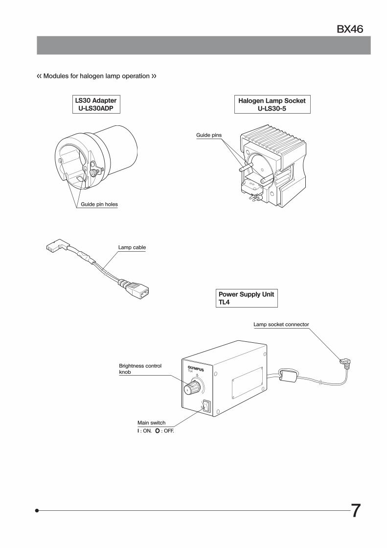
<< Modules for halogen lamp operation >>
LS30 AdapterU-LS30ADP
Guide pin holes
Halogen Lamp SocketU-LS30-5
Guide pins
Power Supply UnitTL4
Lamp cable
Brightness controlknob
Main switch
I : ON. : OFF.
Lamp socket connector

8
33 FLOW OF OBSERVATION
} When the LED lamp is used and the LIM is set, the LED brightness adjustment knob is defeated.} When the halogen bulb is used, set the 32LBD filter in the filter slider and insert it into the insertion slot @.
Set the main switch to “ I ” (ON) and adjust the brightness.
Select the light path (trinocular tube).
Place the specimen on the stage.
Engage the 10X objective in the light path.
Bring the specimen in focus.
Adjust the interpupillary distance.Adjust the diopter.Adjust the light axis.
Adjust the aperture iris and field iris diaphragms.
Engage the objective to be used in the light path and bring the specimen in focus.
Adjust the brightness.
Engage the required filters.
Start observation.
(Controls Used) (Page)
LED lamp Halogen bulb
@ Main switch2 LED brightness adjustment knob*
2 LED brightness adjustment knob*
3 Main switch4 Brightness adjustment knob
4 Brightness adjustment knob
5 Light path selector knob (P. 20)
6 Slide holder (P. 17)7 X-/Y-axis knobs (P. 18)
8 Revolving nosepiece 9 Top lens swing-out lever (P. 12)
a Coarse/fine adjustment knobs (P. 15)
b Binocular tube (P. 11)c Diopter adjustment ring (P. 19)d Condenser height adjustment knob (P. 12)e Condenser centering screws (P. 12)
f Aperture iris diaphragm ring (P. 12)g Field iris diaphragm ring (P. 12)
8 Revolving nosepiece 9 Top lens swing-out lever (P. 12)
h Filter mount (P. 14)
(P. 13)(P. 13)
(P. 13)
* The LED brightness adjustment knob is defeated when the LIM is set (see page 13).
9
BX46
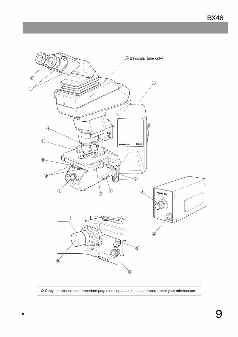
5 (trinocular tube only)
} Copy the observation procedure pages on separate sheets and post it near your microscope.
c
b
8
6
f
e
2
a
9
d
h g
7
1
4
3

10
4 SIMPLIFIED OBSERVATION PROCEDURE
4-1 Basic Operation (Until Observation of Specimen)
Fig. 3
1
This section describes the basic operation of the microscope until the start of observation of a specimen. For the detailed operating procedure of each control, please read the description page specified below.
Press the main switch of the microscope frame to “ I ” (ON).
Fig. 4
Fig. 5
2
3
4
3
4
Rotate the knob to adjust the lamp brightness. (Details: Page 13)
Rotate the knob to lower the stage. (Details: Page 16)
Open the clamping lever of the slide holder and place the specimen slide. (Details: Page 17)
1
2

11
BX46
Fig. 6
5
6
7
Rotate the revolving nosepiece to engage the 10X objective in the light path.
Rotate the coarse and fine adjustment knobs to bring the specimen in focus. (Details: Page 19)
Rotate the stage knob to adjust the observation position.
Now you can observe the magnified image of the specimen. To improve the observation further, read section 4-2, “Microscope Adjustments” below.
4-2 Microscope Adjustments (How to Improve the Observed Image)
Fig. 7
Fig. 8
1
1
Adjust the microscope as described below to improve the observed image.
1 Adjusting the Interpupillary Distance
While looking through the eyepieces, adjust for binocular vision until the left and right fields of view coincide completely. } Note your interpupillary distance so that it can be quickly duplica-
ted.
2 Adjusting the Diopter
The diopter adjustment ensures parfocality from low to high magni-fications and makes it possible to avoid defocusing even when the objective is switched.For details, see page 19.
5
67

12
1
2
3
4
5
6
7
8
9
10
11
Place the specimen.
Rotate the revolving nosepiece to select the 10X objective.
Raise the lever to engage the top lens in the light path.
Rotate the knobs to bring the specimen in focus.
Rotate the knob to raise the condenser to its upper limit.
Rotate the field iris diaphragm ring in the direction of the arrow so that the diaphragm image comes inside the field of view.
Rotate the knobs to focus on the field iris diaphragm image (A in Fig. 9).
Pull out the two condenser centering screws.
Insert the two condenser centering screws into the condenser centering thread holes and turn the two condenser centering screws to move the iris diaphragm image to the center of the field of view (B in Fig. 9).
Gradually open the field iris diaphragm until its image is inscribed in the field of view (C in Fig. 9).
Open the field diaphragm slightly until its image circumscribes the field of view slightly (D in Fig. 9).
} With the 100X objective, the field iris diaphragm image cannot be observed unless the iris diaphragm is minimized. With the 4X objective, maximize the iris diaphragm to observe it.
1
2
1
Fig. 9 Movement of Field Iris Diaphragm Image
A B C D
3 Adjusting the Centering
4 Adjusting the Contrast
NA scale
Set the condenser aperture iris diaphragm ring so that the condenser NA scale position indicates 70% of the NA of the objective in use. After this, observe the image and fine adjust the aperture iris diaphragm to the desired condition.
The image of the aperture iris diaphragm can be viewed by removing the eyepieces and looking into the observation tube. Adjust so that the image looks approximately like that shown in the figure above.
2
Aperture irisdiaphragm image
Objective pupil
70-80%
30-20%
1
2
5 67
8
10 11
9
34
13
BX46
5 USING THE CONTROLS
5-1 Base
Fig. 10
Fig. 11
Fig. 12
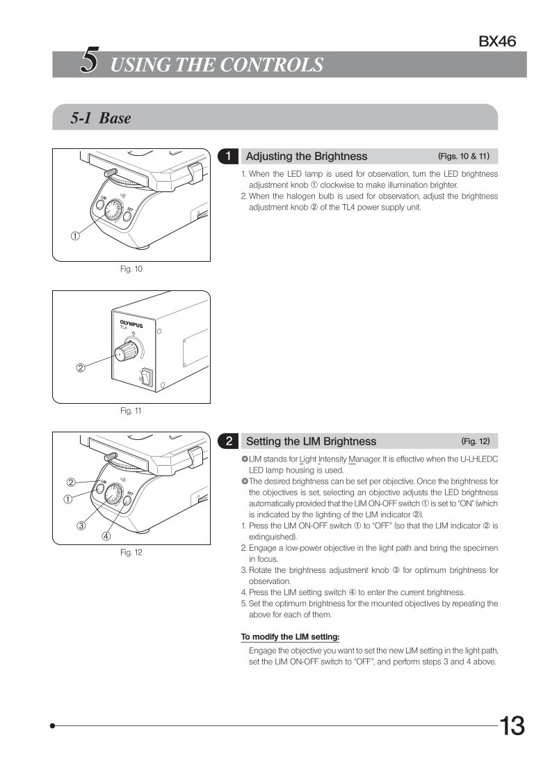
1 Adjusting the Brightness (Figs. 10 & 11)
1. When the LED lamp is used for observation, turn the LED brightness adjustment knob @ clockwise to make illumination brighter.
2. When the halogen bulb is used for observation, adjust the brightness adjustment knob 2 of the TL4 power supply unit.
2 Setting the LIM Brightness (Fig. 12)
} LIM stands for Light Intensity Manager. It is effective when the U-LHLEDC LED lamp housing is used.
} The desired brightness can be set per objective. Once the brightness for the objectives is set, selecting an objective adjusts the LED brightness automatically provided that the LIM ON-OFF switch @ is set to “ON” (which is indicated by the lighting of the LIM indicator 2).
1. Press the LIM ON-OFF switch @ to “OFF” (so that the LIM indicator 2 is extinguished).
2. Engage a low-power objective in the light path and bring the specimen in focus.
3. Rotate the brightness adjustment knob 3 for optimum brightness for observation.
4. Press the LIM setting switch 4 to enter the current brightness.5. Set the optimum brightness for the mounted objectives by repeating the
above for each of them.
To modify the LIM setting:
Engage the objective you want to set the new LIM setting in the light path, set the LIM ON-OFF switch to “OFF”, and perform steps 3 and 4 above.
1
2
1
2
34

14
Fig. 13
3 Using the Filters (Fig. 13)
} One of the filters listed below can be engaged in the light path by inserting the filter @ in the filter slider 2 and engaging the filter slider in the light path.
Usable Filters Applications
32LND1.5/3/6/12/25/50For light brightness control, transmittance 1.5/3/6/12/25/50%
32LBD For color temperature conversion
32IF550 For B&W contrast (Green)
} The LBD filter is not required when the LED lamp is used.
What is LBD filter?The color of the sun at the noon of a clear day is called the daylight color, which looks white to human eyes. On the other hand, the halogen bulb used as the light source of this microscope does not emit the daylight-color light. so the LBD filter is engaged in the light path to convert the color of halogen bulb light into daylight. In general, engaging the LBD filter makes it possible to observe specimens in natural color tones.
1
2

15
BX46
5-2 Focusing Block
Fig. 14
Fig. 15
Fig. 16
1
2
5
1
3
4
} The stage of this microscope is fixed at a low height to facilitate replacement of specimens. Take care not to let your hand and fingers interfere with the stage when operating the coarse adjustment knob.
1 Focusing Controls (Figs. 14 & 15)
The focusing block consists of the controls listed in the following table, which also describes the functions of the controls.
No. Name Function
1 Coarse adjustment knob
Moves the focus position widely.
2 Fine adjustment dial Fine adjusts the focus position.
3 Fine adjustment knob
Fine adjusts the focus position. This knob can be attached to the fine adjustment dial on either the left or right side. (When the microscope is shipped, it is attached to the right-side dial.)
4 Pre-focusing lever Sets the lower limit of the objective position (to prevent contact between the specimen and objective).
5 Tension adjustment ring
Adjusts the force required to rotate the coarse adjustment knob.
2 Adjusting the Focus (Fig. 16)
With both the coarse adjustment knob @ and fine adjustment knob 2, rotating the knob in the direction of the arrow raises the objective (lets the specimen approach the objective).
1
2

16
Fig. 17
Fig. 19
3 Replacing the Fine Adjustment Knob (Fig. 17)
The fine adjustment knob has been attached on the left side at the factory.
} The fine adjustment knob is designed detachable to prevent interference with hand during manipulation of the X-and Y-axis knobs.
Usually attach the fine adjustment knob on the opposite side to the X- and Y-axis knobs.
1. Pull and remove the rubber cap @ from the fine adjustment knob.2. Using the Allen screwdriver, loosen the clamping screw 2 and remove
the fine adjustment knob 3.3. Remove the seal from the fine adjustment knob screw hole on the other
side and attach the knob by reversing the removal procedure.4. Attach a provided seal on the screw hole 5 of the fine adjustment dial
|, from which the fine adjustment knob has been removed.} The fine adjustment dial | can be operated with your fingertip or finger
surface at the same time as manipulating the X- and Y-axis knobs.
4 Adjusting the Coarse Adjustment Knob Tension (Fig. 18)
Adjust the coarse adjustment knob tension using the tension adjustment ring @.
The coarse adjustment knob tension is preadjusted for easy use. However, if desired, you can change the tension using the tension adjustment ring @. Turning the ring in the direction of the arrow increases tension, and vice versa.
The tension is too low if the stage drops by itself of focus is quickly lost after adjustment with the fine adjustment knob. In this case, turn the ring in the direction of the arrow to increase tension.
5 Pre-focusing Lever (Fig. 19)
} The pre-focusing lever ensures that the objective does not come in contact with the specimen and simplifies focusing.
After focusing on the specimen with the coarse adjustment knob, turn this lever @ in the direction of the arrow and lock; the lower limit on coarse adjustment movement is set at the locked position.
After changing a specimen, approximate refocusing is easily accomplis-hed by rotating the coarse adjustment knob to reach the pre-focused position. After this, all you have to do is make fine adjustments with the fine adjustment knob.
} The objective’s vertical movement activated by the fine adjustment knob is not locked.
} When the pre-focusing lever is locked, a coarse movement stroke is reduced due to the microscope’s mechanism, causing the revolving nosepiece not to be able to be lowered to the lower limit. To lower the revolving nosepiece to the lower limit, release the pre-focusing lever.
1
2 3 5
4
1
CAUTION
CAUTION
Fig. 18
1

17
BX46
Fig. 20
Fig. 21
5-3 Stage
} When the U-SP plain stage is used, place the slide specimen directly on the stage because this model does not have the slide holder.
1 Placing the Specimen (Figs. 20 & 21)
} The dimensions of the slide glass should be 26 x 76 mm with thickness of 0.9 to 1.2 mm, and the cover glass should have thickness of 0.17 mm.
} When observing very large specimens, remove the slide holder and place the specimen directly on the stage.
Microscopy with Double-Slide Holder (Fig. 20)
1. Turn the coarse adjustment knob @ to upper the objective.2. Open the spring-loaded curved finger 2 on the slide holder and place
one or two specimen slides on the stage from the front.3. After placing the sides as far as they will go, gently release the curved
finger.
Microscopy with Single-Slide Holder (Fig. 21)
The specimen side can easily be placed by sliding it into the slide holder from the front.
1
2
18
Fig. 22
Fig. 23
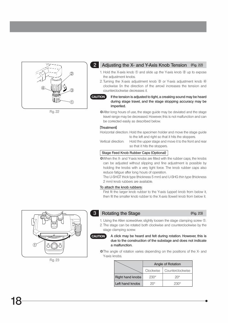
2 Adjusting the X- and Y-Axis Knob Tension (Fig. 22)
1. Hold the X-axis knob @ and slide up the Y-axis knob 2 up to expose the adjustment knobs.
2. Turning the X-axis adjustment knob 3 or Y-axis adjustment knob | clockwise (in the direction of the arrow) increases the tension and counterclockwise decreases it.
If the tension is adjusted to tight, a creaking sound may be heard during stage travel, and the stage stopping accuracy may be imperiled.
} After long hours of use, the stage guide may be deviated and the stage travel range may be decreased. However, this is not malfunction and can be corrected easily as described below.
[Treatment]Horizontal direction: Hold the specimen holder and move the stage guide
to the left and right so that it hits the stoppers.Vertical direction: Hold the upper stage and move it to the front and rear
so that it hits the stoppers.
Stage Feed Knob Rubber Caps (Optional)
}When the X- and Y-axis knobs are fitted with the rubber caps, the knobs can be adjusted without slipping and fine adjustment is possible by holding the knobs with a very light force. The knob rubber caps also reduce fatigue after long hours of operation.
The U-SHGT thick type (thickness 5 mm) and U-SHG thin type (thickness 2 mm) knob rubbers are available.
To attach the knob rubbers: First fit the larger knob rubber to the Y-axis (upper) knob from below it,
then fit the smaller knob rubber to the X-axis (lower) knob from below it.
3 Rotating the Stage (Fig. 23)
1. Using the Allen screwdriver, slightly loosen the stage clamping screw @.2. The stage can be rotated both clockwise and counterclockwise by the
stage clamping screw.
A click may be heard and felt during rotation. However, this is due to the construction of the substage and does not indicate a malfunction.
} The angle of rotation varies depending on the positions of the X- and Y-axis knobs.
Angle of Rotation
Clockwise Counterclockwise
Right hand knobs 230° 20°
Left hand knobs 20° 230°
CAUTION
CAUTION
1
3
2
4
1
19
BX46
Fig. 24
Fig. 25
5-4 Observation Tube
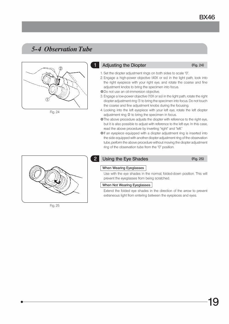
1 Adjusting the Diopter (Fig. 24)
1. Set the diopter adjustment rings on both sides to scale “0”.2. Engage a high-power objective (40X or so) in the light path, look into
the right eyepiece with your right eye, and rotate the coarse and fine adjustment knobs to bring the specimen into focus.
} Do not use an oil-immersion objective.3. Engage a low-power objective (10X or so) in the light path, rotate the right
diopter adjustment ring @ to bring the specimen into focus. Do not touch the coarse and fine adjustment knobs during the focusing.
4. Looking into the left eyepiece with your left eye, rotate the left diopter adjustment ring 2 to bring the specimen in focus.
} The above procedure adjusts the diopter with reference to the right eye, but it is also possible to adjust with reference to the left eye. In this case, read the above procedure by inverting “right” and “left.”
} If an eyepiece equipped with a diopter adjustment ring is inserted into the side equipped with another diopter adjustment ring of the observation tube, perform the above procedure without moving the diopter adjustment ring of the observation tube from the “0” position.
2 Using the Eye Shades (Fig. 25)
When Wearing Eyeglasses
Use with the eye shades in the normal, folded-down position. This will prevent the eyeglasses from being scratched.
When Not Wearing Eyeglasses
Extend the folded eye shades in the direction of the arrow to prevent extraneous light from entering between the eyepieces and eyes.
1
2
20
Fig. 26
Fig. 27
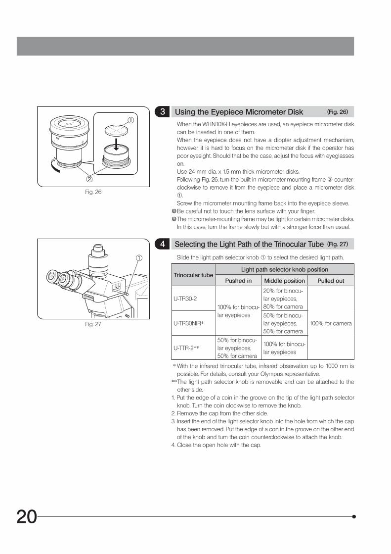
3 Using the Eyepiece Micrometer Disk (Fig. 26)
When the WHN10X-H eyepieces are used, an eyepiece micrometer disk can be inserted in one of them.
When the eyepiece does not have a diopter adjustment mechanism, however, it is hard to focus on the micrometer disk if the operator has poor eyesight. Should that be the case, adjust the focus with eyeglasses on.
Use 24 mm dia. x 1.5 mm thick micrometer disks. Following Fig. 26, turn the built-in micrometer-mounting frame 2 counter-
clockwise to remove it from the eyepiece and place a micrometer disk @.
Screw the micrometer mounting frame back into the eyepiece sleeve.} Be careful not to touch the lens surface with your finger.} The micrometer-mounting frame may be tight for certain micrometer disks.
In this case, turn the frame slowly but with a stronger force than usual.
4 Selecting the Light Path of the Trinocular Tube (Fig. 27)
Slide the light path selector knob @ to select the desired light path.
Trinocular tubeLight path selector knob position
Pushed in Middle position Pulled out
U-TR30-2100% for binocu-lar eyepieces
20% for binocu-lar eyepieces, 80% for camera
100% for cameraU-TR30NIR*50% for binocu-lar eyepieces, 50% for camera
U-TTR-2**50% for binocu-lar eyepieces, 50% for camera
100% for binocu-lar eyepieces
* With the infrared trinocular tube, infrared observation up to 1000 nm is possible. For details, consult your Olympus representative.
** The light path selector knob is removable and can be attached to the other side.
1. Put the edge of a coin in the groove on the tip of the light path selector knob. Turn the coin clockwise to remove the knob.
2. Remove the cap from the other side.3. Insert the end of the light selector knob into the hole from which the cap
has been removed. Put the edge of a con in the groove on the other end of the knob and turn the coin counterclockwise to attach the knob.
4. Close the open hole with the cap.
2
1
1

21
BX46
Fig. 28
Fig. 29
Fig. 30
Fig. 31
5 Adjusting the Tilt (Figs. 28 to 31)
Adjust the height and tilt of the observation tube to obtain the most comfortable viewing position.
U-TBI-3 5° to 35°
U-TBI-3-CLI 5° to 35°
U-ETBI 0° to 25°
U-TTBI 0° to 25°
U-TTR-2 5° to 35°
U-TTLBI 0° to 27°
With the U-TBI-3 (Fig. 28)
Holding the binocular section @ with both hands, raise or lower it to the desired position.
Never attempt to force the binocular section past the upper or lower stop position. Applying excessive force could destroy the limiting mechanism.
} The U-TBI-3/U-TBI-3-CLI can be used in combination with only one intermediate attachment.
} If you need photography using the U-TBI-3/U-TBI-3-CLI, use the U-TRU trinocular intermediate tube.
With the U-ETBI/U-TTBI (Fig. 29)
The U-ETBI and U-TTBI are ergonomic observation tubes with normal field, capable of the adjustments of the positioning angle (0° to 25°) as well as front-rear positioning (by 45 mm) of the eyepieces. The U-ETBI is the erect image model and the U-TTBI is the inverted image model, and both models are of the same size.
With the U-TTLBI (Fig. 30)
The U-TTLBI is a Tilting, Telescopic, Lifting binocular tube with the following adjustment capabilities.
· Eyepiece angle adjustment (0° to 27°) · Eyepiece up-down position adjustment (45 mm) · Observation tube front-rear position adjustment (55 mm)
} When adjusting front-rear position of the observation tube, hold the base of the observation tube as shown in Fig. 31.
} When storing the microscope, increase the angle of the eyepieces so as to prevent the eyepieces from dropping.
} To adjust the up-down position of the eyepiece, turn the dial 2.
The intermediate attachments that can be combined with the U-TTBI and U-TTLBI are limited. For details, please contact Olympus.
CAUTION
CAUTION
15° to 35°
2

22
Fig. 32
6 Using Eyepieces Incorporating a Micrometer (Fig. 32)
} When the eyepieces in use incorporate a micrometer, the accuracy of the left-right focusing adjustment (diopter adjustment) can be improved further.
1. Looking into the right eyepiece with your right eye, turn the top of the eyepiece @ so that the micrometer in the field of view looks sharpest (Fig. 32).
2. Looking into the right eyepiece, rotate the coarse and fine adjustment knobs to bring the specimen and micrometer (cross lines, etc.) into focus.
3. Looking into the left eyepiece with your left eye, rotate the diopter adjustment ring 2 to bring the specimen into focus.
1
2
5-5 Condenser For how to adjust the centering of the condenser, see page 12.
1 Compatibility of Objectives and Condensers
Objective Magnification BX45 Condenser Field iris diaphragm Aperture iris diaphragm
2X/4X Applicable by swing the top lens out. Used as the aperture iris diaphragm
Opened
10X/20X/40X Applicable by engaging the top lens in the light path.
Field iris diaphragm Aperture iris diaphragm
} The 1.25X to 2X objectives can also be used but the surroundings of the field of view may become dark.

23
BX46
Fig. 34
5-6 Immersion Objectives
Be sure to use the provided Olympus Immersion oil.
1 Using Immersion Objectives (Fig. 34)
1. Focus on the specimen with objectives in the order of lower-power to higher-power ones.
2. Before engaging the immersion objective, place a drop of provided immersion oil onto the specimen at the area to be observed.
3. Turn the revolving nosepiece to engage the immersion objective, then focus using the fine adjustment knob.
Since air bubbles in the oil will affect the image quality, make sure that the oil is free of bubbles.
a. To check for bubbles, remove the eyepiece and fully open the field and aperture iris diaphragms, then look at the exit pupil of the objective inside the observation tube. (The pupil should appear round and bright.)
b. To remove bubbles, turn the revolving nosepiece to repeatedly defocus and refocus the oil immersion objective.
} If the condenser engraving shows a numerical aperture (NA) of 1.0 or higher, the number applies only when oil is applied between the slide glass and the top surface of the condenser. When oil is not present, the NA is about 0.9.
4. After use, remove immersion oil from the objective front lens by wiping with gauze slightly moistened with absolute alcohol.
Caution in use of immersion oil
If immersion oil enters your eyes or contacts with your skin, imme-diately take the following treatment. Eyes: Rinse with fresh water (for 15 minutes or more). Skin: Rinse with water and soap.If the appearance of the eyes or skin is altered or pain persists, immediately see your doctor.
CAUTION
CAUTION
CAUTION
24
66 CAMERA RECORDING
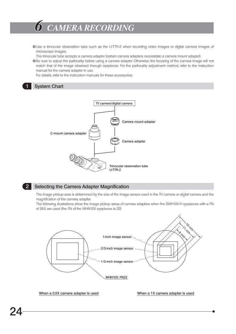
} Use a trinocular observation tube such as the U-TTR-2 when recording video images or digital camera images of microscope images.
The trinocular tube accepts a camera adapter (certain camera adapters necessitate a camera mount adapter).} Be sure to adjust the parfocality before using a camera adapter. Otherwise, the focusing of the camera image will not
match that of the image observed through eyepieces. For the parfocality adjustment method, refer to the instruction manual for the camera adapter in use.
For details, refer to the instruction manuals for these accessories.
1 System Chart
TV camera/digital camera
Camera mount adapter
Camera adapter
C-mount camera adapter
Trinocular observation tubeU-TTR-2
2 Selecting the Camera Adapter Magnification
The image pickup area is determined by the size of the image sensor used in the TV camera or digital camera and the magnification of the camera adapter.
The following illustrations show the image pickup areas of camera adapters when the SWH10X-H eyepieces with a FN of 26.5 are used (the FN of the WHN10X eyepieces is 22).
1-inch image sensor
2/3-inch image sensor
1/2-inch image sensor
WHN10X: FN22
When a 0.5X camera adapter is used When a 1X camera adapter is used
25
BX46
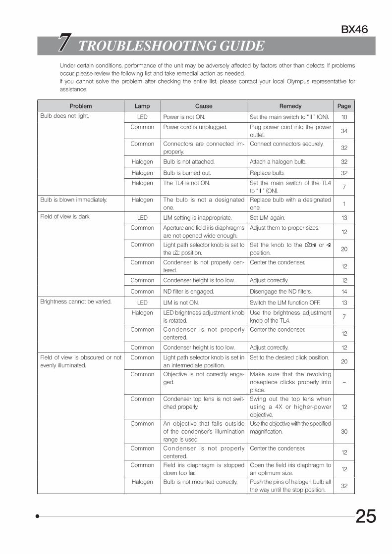
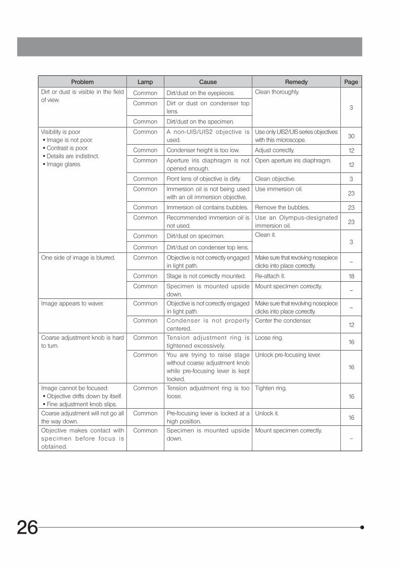
7 TROUBLESHOOTING GUIDE Under certain conditions, performance of the unit may be adversely affected by factors other than defects. If problems
occur, please review the following list and take remedial action as needed. If you cannot solve the problem after checking the entire list, please contact your local Olympus representative for
assistance.
Problem Lamp Cause Remedy Page
Bulb does not light. LED Power is not ON. Set the main switch to “ I ” (ON). 10
Common Power cord is unplugged. Plug power cord into the power outlet.
34
Common Connectors are connected im-properly.
Connect connectors securely.32
Halogen Bulb is not attached. Attach a halogen bulb. 32
Halogen Bulb is burned out. Replace bulb. 32
Halogen The TL4 is not ON. Set the main switch of the TL4 to “ I ” (ON).
7
Bulb is blown immediately. Halogen The bulb is not a designated one.
Replace bulb with a designated one.
1
Field of view is dark. LED LIM setting is inappropriate. Set LIM again. 13
Common Aperture and field iris diaphragms are not opened wide enough.
Adjust them to proper sizes.12
Common Light path selector knob is set to the position.
Set the knob to the or position.
20
Common Condenser is not properly cen-tered.
Center the condenser.12
Common Condenser height is too low. Adjust correctly. 12
Common ND filter is engaged. Disengage the ND filters. 14
Brightness cannot be varied. LED LIM is not ON. Switch the LIM function OFF. 13
Halogen LED brightness adjustment knob is rotated.
Use the brightness adjustment knob of the TL4.
7
Common Condenser is not proper ly centered.
Center the condenser.12
Common Condenser height is too low. Adjust correctly. 12
Field of view is obscured or not evenly illuminated.
Common Light path selector knob is set in an intermediate position.
Set to the desired click position.20
Common Objective is not correctly enga-ged.
Make sure that the revolving nosepiece clicks properly into place.
–
Common Condenser top lens is not swit-ched properly.
Swing out the top lens when using a 4X or higher-power objective.
12
Common An objective that falls outside of the condenser’s illumination range is used.
Use the objective with the specified magnification. 30
Common Condenser is not proper ly centered.
Center the condenser.12
Common Field iris diaphragm is stopped down too far.
Open the field iris diaphragm to an optimum size.
12
Halogen Bulb is not mounted correctly. Push the pins of halogen bulb all the way until the stop position.
32
26
Problem Lamp Cause Remedy Page
Dirt or dust is visible in the field of view.
Common Dirt/dust on the eyepieces. Clean thoroughly.
3Common Dirt or dust on condenser top
lens.
Common Dirt/dust on the specimen.
Visibility is poor · Image is not poor. · Contrast is poor. · Details are indistinct. · Image glares.
Common A non-UIS/UIS2 objective is used.
Use only UIS2/UIS series objectives with this microscope.
30
Common Condenser height is too low. Adjust correctly. 12
Common Aperture iris diaphragm is not opened enough.
Open aperture iris diaphragm.12
Common Front lens of objective is dirty. Clean objective. 3
Common Immersion oil is not being used with an oil immersion objective.
Use immersion oil.23
Common Immersion oil contains bubbles. Remove the bubbles. 23
Common Recommended immersion oil is not used.
Use an Olympus-designated immersion oil.
23
Common Dirt/dust on specimen. Clean it.3
Common Dirt/dust on condenser top lens.
One side of image is blurred. Common Objective is not correctly engaged in light path.
Make sure that revolving nosepiece clicks into place correctly.
–
Common Stage is not correctly mounted. Re-attach it. 18
Common Specimen is mounted upside down.
Mount specimen correctly.–
Image appears to waver. Common Objective is not correctly engaged in light path.
Make sure that revolving nosepiece clicks into place correctly.
–
Common Condenser is not proper ly centered.
Center the condenser.12
Coarse adjustment knob is hard to turn.
Common Tension adjustment r ing is tightened excessively.
Loose ring.16
Common You are trying to raise stage without coarse adjustment knob while pre-focusing lever is kept locked.
Unlock pre-focusing lever.
16
Image cannot be focused: · Objective drifts down by itself. · Fine adjustment knob slips.
Common Tension adjustment ring is too loose.
Tighten ring.16
Coarse adjustment will not go all the way down.
Common Pre-focusing lever is locked at a high position.
Unlock it.16
Objective makes contact with spec imen be fo re focus is obtained.
Common Specimen is mounted upside down.
Mount specimen correctly.–

27
BX46
Problem Lamp Cause Remedy Page
Field of view of one eye does not match that of the other.
Common Interpupillary distance is incorrect. Adjust interpupillary distance. 11
Common Diopter adjustment is incorrect. Adjust diopter. 19
Common Different eyepieces are used on left and right.
Change one eyepiece to match the other so that both sides are the same type.
33
Common Your view is not accustomed to microscope observation.
Upon looking into eyepieces, try looking at overall field before concentrating on specimen range. You may also find it helpful to look up and into distance for a moment before looking back into microscope.
–
Image shifts when you touch stage.
Common Stage is not properly mounted. Clamp stage.18
X- and Y-axis knobs are too tight or too loose.
Common Tension of X- and Y-axis knobs is too high or too low.
Adjust tension.18
Stroke has reduced. Common Stage guide is deviated. Correct deviation as described. 18
28
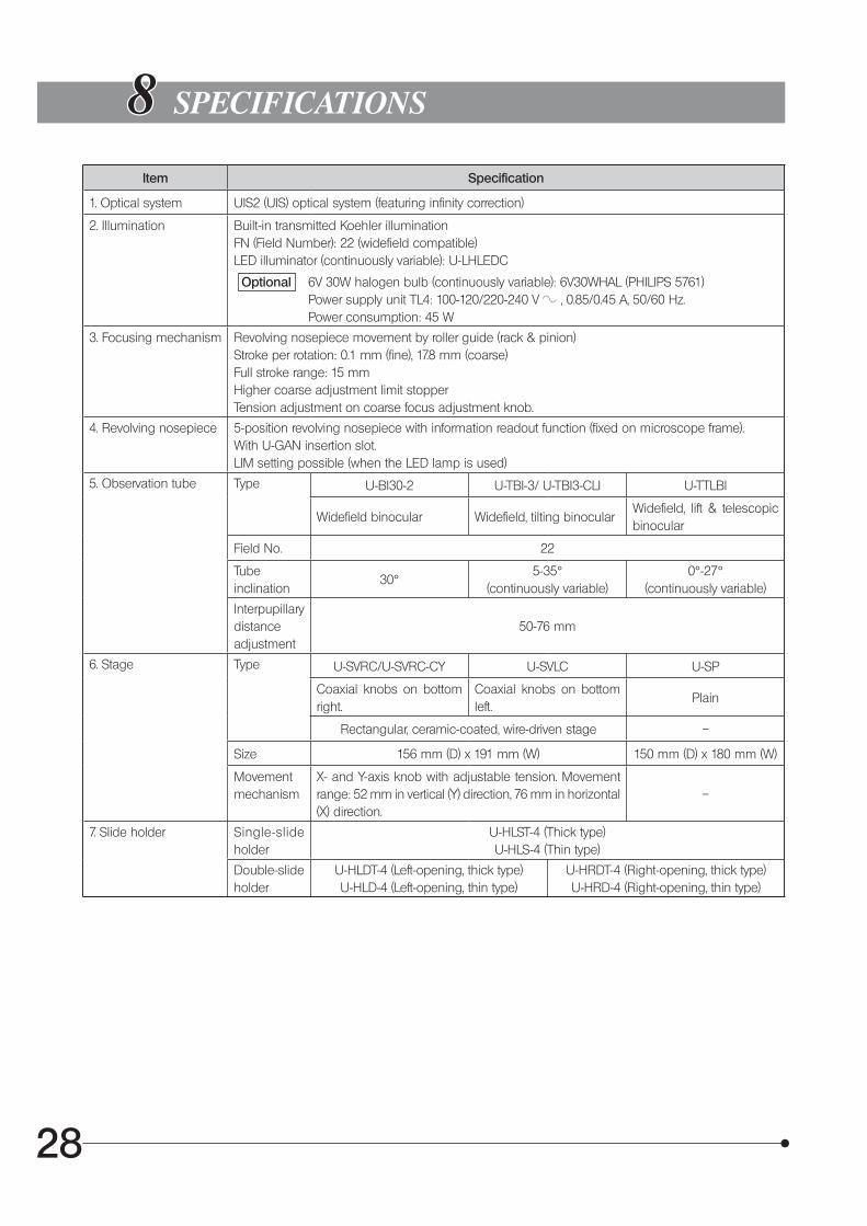
88 SPECIFICATIONS
Item Specification
1. Optical system UIS2 (UIS) optical system (featuring infinity correction)
2. Illumination Built-in transmitted Koehler illuminationFN (Field Number): 22 (widefield compatible)LED illuminator (continuously variable): U-LHLEDC
Optional 6V 30W halogen bulb (continuously variable): 6V30WHAL (PHILIPS 5761) Power supply unit TL4: 100-120/220-240 V $ , 0.85/0.45 A, 50/60 Hz. Power consumption: 45 W
3. Focusing mechanism Revolving nosepiece movement by roller guide (rack & pinion)Stroke per rotation: 0.1 mm (fine), 17.8 mm (coarse)Full stroke range: 15 mmHigher coarse adjustment limit stopperTension adjustment on coarse focus adjustment knob.
4. Revolving nosepiece 5-position revolving nosepiece with information readout function (fixed on microscope frame).With U-GAN insertion slot.LIM setting possible (when the LED lamp is used)
5. Observation tube Type U-BI30-2 U-TBI-3/ U-TBI3-CLI U-TTLBI
Widefield binocular Widefield, tilting binocularWidefield, lift & telescopic binocular
Field No. 22
Tubeinclination
30°5-35°
(continuously variable)0°-27°
(continuously variable)
Interpupillary distanceadjustment
50-76 mm
6. Stage Type U-SVRC/U-SVRC-CY U-SVLC U-SP
Coaxial knobs on bottom right.
Coaxial knobs on bottom left.
Plain
Rectangular, ceramic-coated, wire-driven stage –
Size 156 mm (D) x 191 mm (W) 150 mm (D) x 180 mm (W)
Movement mechanism
X- and Y-axis knob with adjustable tension. Movement range: 52 mm in vertical (Y) direction, 76 mm in horizontal (X) direction.
–
7. Slide holder Single-slide holder
U-HLST-4 (Thick type)U-HLS-4 (Thin type)
Double-slide holder
U-HLDT-4 (Left-opening, thick type)U-HLD-4 (Left-opening, thin type)
U-HRDT-4 (Right-opening, thick type)U-HRD-4 (Right-opening, thin type)
29
BX46
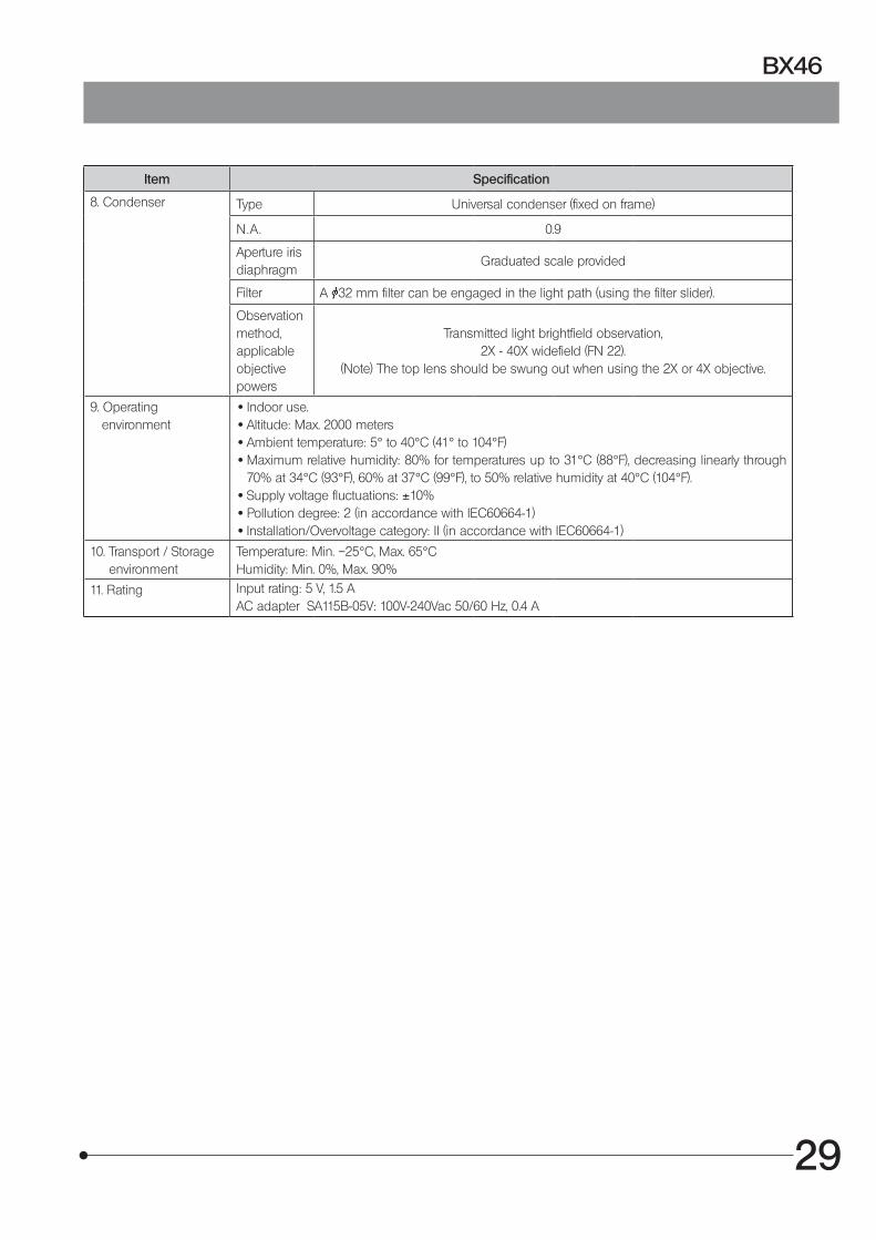
Item Specification
8. Condenser Type Universal condenser (fixed on frame)
N.A . 0.9
Aperture iris diaphragm
Graduated scale provided
Filter A 32 mm filter can be engaged in the light path (using the filter slider).
Observation method, applicable objective powers
Transmitted light brightfield observation,2X - 40X widefield (FN 22).
(Note) The top lens should be swung out when using the 2X or 4X objective.
9. Operating environment
· Indoor use. · Altitude: Max. 2000 meters · Ambient temperature: 5° to 40°C (41° to 104°F) · Maximum relative humidity: 80% for temperatures up to 31°C (88°F), decreasing linearly through
70% at 34°C (93°F), 60% at 37°C (99°F), to 50% relative humidity at 40°C (104°F). · Supply voltage fluctuations: ±10% · Pollution degree: 2 (in accordance with IEC60664-1) · Installation/Overvoltage category: II (in accordance with IEC60664-1)
10. Transport / Storage environment
Temperature: Min. –25°C, Max. 65°CHumidity: Min. 0%, Max. 90%
11. Rating Input rating: 5 V, 1.5 AAC adapter SA115B-05V: 100V-240Vac 50/60 Hz, 0.4 A
30
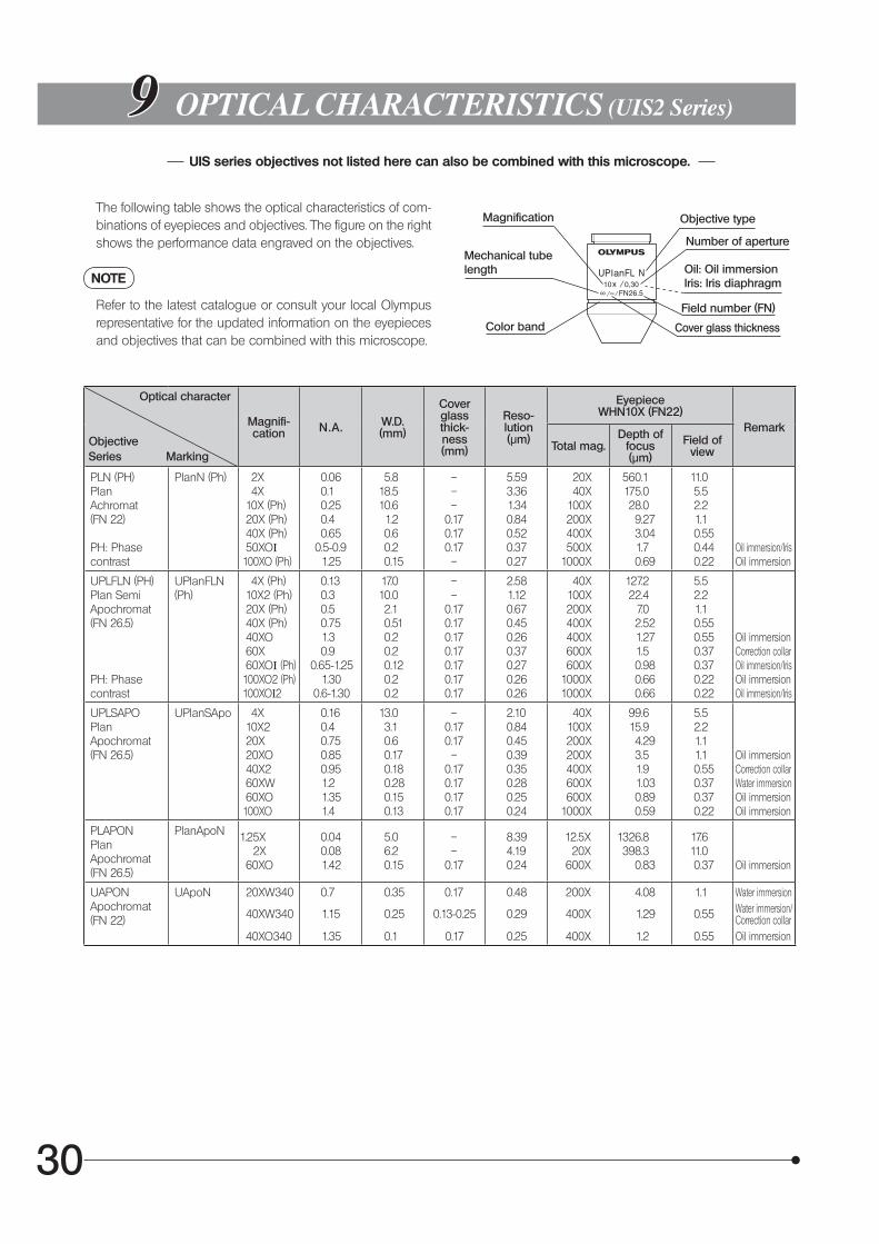
99 OPTICAL CHARACTERISTICS (UIS2 Series)
UIS series objectives not listed here can also be combined with this microscope.
The following table shows the optical characteristics of com-binations of eyepieces and objectives. The figure on the right shows the performance data engraved on the objectives.
NOTE
Refer to the latest catalogue or consult your local Olympus representative for the updated information on the eyepieces and objectives that can be combined with this microscope.
Objective type
Number of aperture
Magnification
Cover glass thickness
Mechanical tubelength
Color band
Oil: Oil immersionIris: Iris diaphragm
Field number (FN)
Magnifi-cation N.A. W.D.
(mm)
Cover glass thick-ness (mm)
Reso-lution(µm)
EyepieceWHN10X (FN22)
Remark
Total mag.Depth of
focus (µm)
Field of view
PLN (PH) PlanAchromat(FN 22)
PH: Phase contrast
PlanN (Ph) 2X 4X 10X (Ph) 20X (Ph) 40X (Ph) 50XOI 100XO (Ph)
0.06 0.1 0.25 0.4 0.65
0.5-0.9 1.25
5.818.510.61.20.60.20.15
–––
0.170.170.17–
5.593.361.340.840.520.370.27
20X40X
100X200X400X500X
1000X
560.1175.028.09.273.041.70.69
11.05.52.21.10.550.440.22
Oil immersion/IrisOil immersion
UPLFLN (PH)Plan SemiApochromat(FN 26.5)
PH: Phase contrast
UPlanFLN (Ph)
4X (Ph) 10X2 (Ph) 20X (Ph) 40X (Ph) 40XO 60X 60XOI (Ph) 100XO2 (Ph) 100XOI2
0.13 0.3 0.5 0.75 1.3 0.9 0.65-1.25 1.30 0.6-1.30
17.010.02.10.510.20.20.120.20.2
––
0.170.170.170.170.170.170.17
2.581.120.670.450.260.370.270.260.26
40X100X200X400X400X600X600X
1000X1000X
127.222.4
7.02.521.271.50.980.660.66
5.52.21.10.550.550.370.370.220.22
Oil immersionCorrection collarOil immersion/IrisOil immersionOil immersion/Iris
UPLSAPOPlanApochromat(FN 26.5)
UPlanSApo 4X 10X2 20X 20XO 40X2 60XW 60XO 100XO
0.16 0.4 0.75 0.85 0.95 1.2 1.35 1.4
13.03.10.60.170.180.280.150.13
–0.170.17–
0.170.170.170.17
2.100.840.450.390.350.280.250.24
40X100X200X200X400X600X600X
1000X
99.615.94.293.51.91.030.890.59
5.52.21.11.10.550.370.370.22
Oil immersionCorrection collarWater immersionOil immersionOil immersion
PLAPONPlanApochromat(FN 26.5)
PlanApoN 1.25X 2X 60XO
0.04 0.08 1.42
5.06.20.15
––
0.17
8.394.190.24
12.5X 20X 600X
1326.8398.3
0.83
17.611.00.37 Oil immersion
UAPONApochromat(FN 22)
UApoN 20XW340
40XW340
40XO340
0.7
1.15
1.35
0.35
0.25
0.1
0.17
0.13-0.25
0.17
0.48
0.29
0.25
200X
400X
400X
4.08
1.29
1.2
1.1
0.55
0.55
Water immersionWater immersion/Correction collarOil immersion
Optical character
ObjectiveSeries Marking
6
7
7
5
8
2
2
2
22
99
4
3
1
31
BX46
1010 ASSEMBLY
10-1 Assembly Diagram
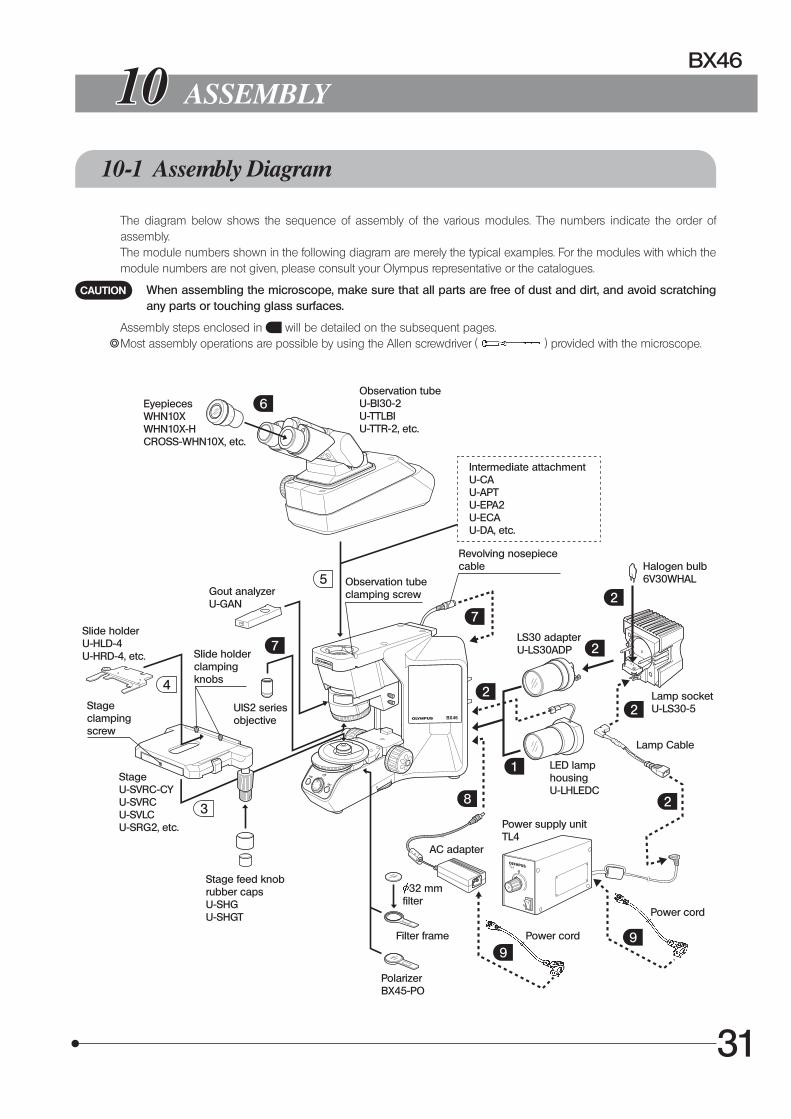
The diagram below shows the sequence of assembly of the various modules. The numbers indicate the order of assembly.
The module numbers shown in the following diagram are merely the typical examples. For the modules with which the module numbers are not given, please consult your Olympus representative or the catalogues.
When assembling the microscope, make sure that all parts are free of dust and dirt, and avoid scratching any parts or touching glass surfaces.
Assembly steps enclosed in will be detailed on the subsequent pages.} Most assembly operations are possible by using the Allen screwdriver ( ) provided with the microscope.
EyepiecesWHN10XWHN10X-HCROSS-WHN10X, etc.
Slide holderU-HLD-4U-HRD-4, etc.
UIS2 series objective
Slide holder clamping knobs
Gout analyzer U-GAN
Stage clamping screw
Stage feed knob rubber capsU-SHGU-SHGT
Observation tubeU-BI30-2U-TTLBIU-TTR-2, etc.
Intermediate attachmentU-CAU-APTU-EPA2U-ECAU-DA, etc.
Observation tube clamping screw
Revolving nosepiece cable
LS30 adapterU-LS30ADP
Halogen bulb6V30WHAL
Lamp socketU-LS30-5
LED lamp housingU-LHLEDC
Lamp Cable
Power supply unitTL4
AC adapter
Power cord
Power cord
32 mm filter
Filter frame
Polarizer BX45-PO
CAUTION
StageU-SVRC-CYU-SVRCU-SVLCU-SRG2, etc.
32
10-2 Detailed Assembly Procedures
Fig. 35
Fig. 36
Fig. 37
Fig. 38
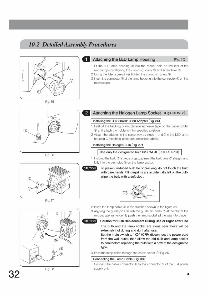
1 Attaching the LED Lamp Housing (Fig. 35)
1. Fit the LED lamp housing @ into the mount hole on the rear of the microscope by aligning the clamping screw 2 and screw hole 3.
2. Using the Allen screwdriver, tighten the clamping screw 2.3. Insert the connector | of the lamp housing into the connector 5 on the
microscope.
2 Attaching the Halogen Lamp Socket (Figs. 36 to 38)
Installing the U-LS30ADP LS30 Adapter (Fig. 36)
1. Peel off the backing of double-side adhesive tape on the cable holder @ and attach the holder on the specified position.
2. Attach the adapter in the same way as steps 1 and 2 in the LED lamp housing C attaching procedure described above.
Installing the Halogen Bulb (Fig. 37)
Use only the designated bulb 6V30WHAL (PHILIPS 5761).
1. Holding the bulb 2 a piece of gauze, insert the bulb pins 3 straight and fully into the pin holes | on the lamp socket.
To prevent reduced bulb life or cracking, do not touch the bulb with bare hands. If fingerprints are accidentally left on the bulb, wipe the bulb with a soft cloth.
2. Insert the lamp cable 5 in the direction shown in the figure 38.3. Aligning the guide pins 6 with the guide pin holes 7 at the rear of the
microscope frame, gently push the lamp socket all the way into place.
Caution for Bulb Replacement During Use or Right After Use
The bulb and the lamp socket are areas near these will be extremely hot during and right after use.
Set the main switch to “ ” (OFF), disconnect the power cord from the wall outlet, then allow the old bulb and lamp socket to cool before replacing the bulb with a new of the designated type.
4 Pass the lamp cable through the cable holder @ (Fig. 36).
Connecting the Lamp Cable (Fig. 38)
Connect the cable connector 8 to the connector 9 of the TL4 power supply unit.
CAUTION
CAUTION
1
1
2
43
5
2
34
5
6
7
89
33
BX46
Fig. 39
1
2
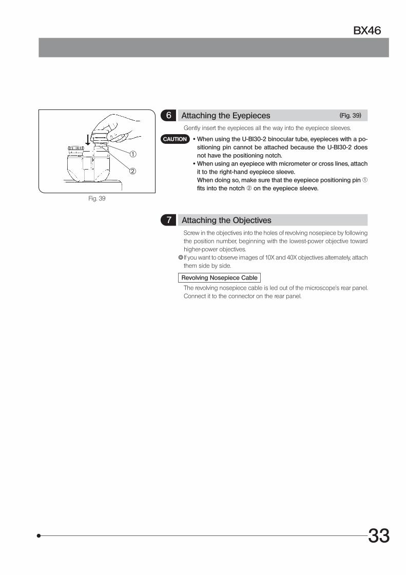
6 Attaching the Eyepieces (Fig. 39)
Gently insert the eyepieces all the way into the eyepiece sleeves.
· When using the U-BI30-2 binocular tube, eyepieces with a po-sitioning pin cannot be attached because the U-BI30-2 does not have the positioning notch.
· When using an eyepiece with micrometer or cross lines, attach it to the right-hand eyepiece sleeve.
When doing so, make sure that the eyepiece positioning pin @ fits into the notch 2 on the eyepiece sleeve.
7 Attaching the Objectives Screw in the objectives into the holes of revolving nosepiece by following
the position number, beginning with the lowest-power objective toward higher-power objectives.
} If you want to observe images of 10X and 40X objectives alternately, attach them side by side.
Revolving Nosepiece Cable
The revolving nosepiece cable is led out of the microscope’s rear panel. Connect it to the connector on the rear panel.
CAUTION

34
Fig. 40
Fig. 41
Fig. 42
Fig. 43
8 Attaching the AC Adapter (Fig. 40)
· Cables and cords are vulnerable when bent or twisted. Never subject them to excessive force.
· Make sure that the main switch is set to “ ” (OFF) before connecting the power cord (Fig. 40).
1. Insert the connector @ of the AC adapter firmly into the connector 2 on the microscope.
Always use the designated AC adapter. Using a non-designated AC adapter may cause malfunction.
9 Attaching the Power Cord (Figs. 41 to 43)
Always use the power cord provided by Olympus. If no power cord is provided with the microscope, please select the proper power cord by referring to section “ PROPER SELECTION OF THE POWER SUPPLY CORD ” at the end of this instruction manual.
Operation Using the AC Adapter (Fig. 41)
1. Insert the connector @ of the power cord firmly into the input connector 2 of the AC adapter (Fig. 41).
The power cord should be connected to a grounded/earthed, 3-conductor power outlet. If the power outlet is not grounded/earthed properly, Olympus can no longer warrant the electrical safety performance of the equipment.
2. Plug the power cord plug 3 into the wall outlet 4 (Fig. 43).
Should the power cord come in contact with the hot lamp socket, the power cord could melt and cause electric shock. Be sure to route the power cord away from the lamp socket.
Operation Using the TL4 Power Supply Unit (Fig. 42)
} The following operation is not required when the LED lamp is used.1. Insert the connector @ of the power cord firmly into the input connector
2 of the TL4 (Fig. 42).2. Plug the power cord plug 3 into the wall outlet 4 (Fig. 43).
43
CAUTION
CAUTION
CAUTION
CAUTION
CAUTION
12
1
2
2
1

35
BX46
11 HALOGEN LAMP SOCKET INSPECTION SHEET
{ For safe use of the lamp socket, we recommend performing the following inspection periodically (every time you replace the lamp bulb and at least every 6 months).
{ The table below identified the check items to be observed. Put (X) if not applicable or ( ) if applicable.{ If there is any ( ) mark noted, immediately stop use of the product, and consult Olympus for detailed inspections or replace
the lamp soket.{ If you detect an abnormality other than that listed below or with other Olympus product, also stop the use of the product and
contact Olympus for detailed inspections.{Note that the service, replacement and detailed inspections are charged after expiration of the warranty period.
If you have any questions, please contact Olympus.
Check results (Date)
Check items / / / /
1. More than 8 years have passed since original purchase or the total power ON time exceeds 20,000 hours.
2. Lamp does not light sometimes even though the main switch is set to on.
3. Illumination flickers when you move the lamp cable or lamp socket.
4. Scorching or burning odor is produced during use.
5. Illumination still flickers after replacement with a new lamp bulb.
6. Deformation, backlash, or looseness, etc. when you assemble the lamp socket.
7. Extreme discoloration of the lamp socket connection terminal or lamp socket lamp bulb mount.
8. Discoloration, deformation or cracking of the lamp socket.
9. Melting, crack, deformation or solidification of the lamp cable or a wiring part.
10. Increased frequency of servicing compared to similar devices put into use at the same time as the lamp socket.
* When the Check Result columns become insufficient, copy this sheet.

36
n PROPER SELECTION OF THE POWER SUPPLY CORD
If no power supply cord is provided, please select the proper power supply cord for the equipment by referring to “ Specifications ” and “ Certified Cord ” below:CAUTION: In case you use a non-approved power supply cord for Olympus products, Olympus can no longer warrant the
electrical safety of the equipment.
Specifications
Voltage RatingCurrent RatingTemperature RatingLengthFittings Configuration
125V AC (for 100-120V AC area) or, 250V AC (for 220-240V AC area)6A minimum60˚C minimum3.05 m maximumGrounding type attachment plug cap. Opposite terminates in molded-on IEC configuration appliance coupling.
Table 1 Certified Cord
A power supply cord should be certified by one of the agencies listed in Table 1 , or comprised of cordage marked with an agency marking per Table 1 or marked per Table 2. The fittings are to be marked with at least one of agencies listed in Table 1. In case you are unable to buy locally in your country the power supply cord which is approved by one of the agencies mentioned in Table 1, please use replacements approved by any other equivalent and authorized agencies in your country.
Country AgencyCertification
Mark Country AgencyCertification
Mark
Argentina IRAM Italy IMQ
Australia SAA Japan JET, JQA, TÜV,UL-APEX/MITI
Austria ÖVE Netherlands KEMA
Belgium CEBEC Norway NEMKO
Canada CSA Spain AEE
Denmark DEMKO Sweden SEMKO
Finland FEI Switzerland SEV
France UTE United Kingdom
ASTABSI
Germany VDE U.S.A. UL
Ireland NSAI
37
BX46
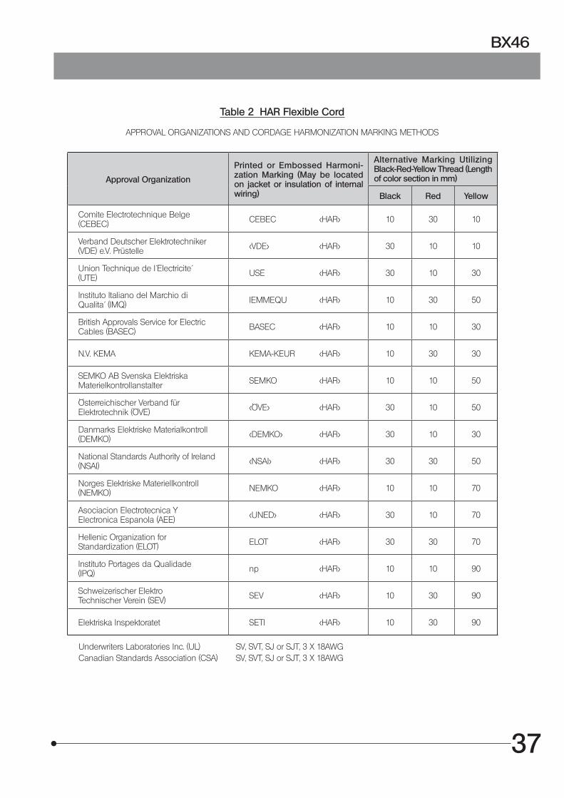
Table 2 HAR Flexible Cord
APPROVAL ORGANIZATIONS AND CORDAGE HARMONIZATION MARKING METHODS
Approval Organization
Printed or Embossed Harmoni-zation Marking (May be located on jacket or insulation of internal wiring)
Alternative Marking Utilizing Black-Red-Yellow Thread (Length of color section in mm)
Black Red Yellow
Comite Electrotechnique Belge(CEBEC) CEBEC <HAR> 10 30 10
Verband Deutscher Elektrotechniker(VDE) e.V. Prüstelle <VDE> <HAR> 30 10 10
Union Technique de I´Electricite´(UTE) USE <HAR> 30 10 30
Instituto Italiano del Marchio diQualita´ (IMQ) IEMMEQU <HAR> 10 30 50
British Approvals Service for ElectricCables (BASEC) BASEC <HAR> 10 10 30
N.V. KEMA KEMA-KEUR <HAR> 10 30 30
SEMKO AB Svenska ElektriskaMaterielkontrollanstalter SEMKO <HAR> 10 10 50
Österreichischer Verband fürElektrotechnik (ÖVE) <ÖVE> <HAR> 30 10 50
Danmarks Elektriske Materialkontroll(DEMKO) <DEMKO> <HAR> 30 10 30
National Standards Authority of Ireland (NSAI) <NSAI> <HAR> 30 30 50
Norges Elektriske Materiellkontroll(NEMKO) NEMKO <HAR> 10 10 70
Asociacion Electrotecnica YElectronica Espanola (AEE) <UNED> <HAR> 30 10 70
Hellenic Organization forStandardization (ELOT) ELOT <HAR> 30 30 70
Instituto Portages da Qualidade(IPQ) np <HAR> 10 10 90
Schweizerischer ElektroTechnischer Verein (SEV) SEV <HAR> 10 30 90
Elektriska Inspektoratet SETI <HAR> 10 30 90
Underwriters Laboratories Inc. (UL) SV, SVT, SJ or SJT, 3 X 18AWG Canadian Standards Association (CSA) SV, SVT, SJ or SJT, 3 X 18AWG

MEMO


Printed in Japan on September 14, 2010 M 010-05