Embed Size (px)
Citation preview
Instructions and operation of the pivoting vertical ventilation device
manufactured by CB2 INDUSTRIES LLC.

TABLE OF CONTENTS
Contents
Introduction ______________________________________________________________________________________________ 1
Installation ________________________________________________________________________________________________ 2
Operation _________________________________________________________________________________________________ 6
Maintenance ____________________________________________________________________________________________ 10
Safety ____________________________________________________________________________________________________ 11
Diagrams ________________________________________________________________________________________________ 12
Replacement Parts _____________________________________________________________________________________ 13
Company Information __________________________________________________________________________________ 13
VENTPROPTM
Page 1
Introduction
THE BASICS
The VENTPROPTM is a patent pending device that provides an efficient and cost effective way to train
firefighters in vertical ventilation. The device can be installed on most simulated roof props or training
facilities built for vertical ventilation. The device is installed over a four foot by four foot hole in the roof and
allows strips of material to be arranged around the perimeter. The cutting strips used can be made of any
material that fits in the device and is appropriate to cut with ventilation saws.
THE BENEFITS
First and foremost is the cost savings. One of the reasons this device was designed was to save cost
during budget cuts. Most training departments use Oriented Strand Board (OSB) or plywood on
their ventilation props. When using 4x8 sheets of material one can only cut one or two ventilation
holes. That same sheet of plywood can be cut into multiple strips, greatly increasing the number of
holes one can cut.
Next is how the device works as a guide for the inexperienced firefighter. Until they cut multiple
ventilation holes, many firefighters struggle with knowing exactly how big a hole they need to cut.
The size and shape of the device allows the firefighter to visualize what size the ventilation hole
should be. The replaceable cutting guide is made of durable UHMV, a tough polyethylene sheet that
will not damage saws if accidently cut.
Furthermore, many firefighters have spent little time on a sloped roof, and may not feel comfortable
carrying a large 4x8 foot sheet of plywood onto the roof. By using disposable cutting strips instead
of sheets of plywood, the firefighter can simply carry four thin strips onto the roof to prepare the
device for the next operation. This can reduce the risk of injuries during vertical ventilation
training.
The device greatly decreases the amount of material needed for training. Because of the design of
the device, the decreased amount and the shape of waste material can also benefit the agency. The
large, irregular shape of plywood or USB sheets take up a huge amount of space. After using the
pivoting vertical ventilation device, the waste is arranged in uniform strips of material no longer
than 48 inches, and only a few inches wide.
By using this device, an agency has much more flexibility in the type of material used in vertical
ventilation training. The device can be used with OSB, plywood, standard 1”x6” lumber, 3/4” x 6”
fence boards, 2”x6” lumber (with optional extension), wooden boards recovered from freight
pallets, and even the shipping crate that the device came in can be disassembled and used. Because
of this benefit, some departments may completely eliminate material cost for ventilation training by
using local resources to acquire materials.
VENTPROPTM
Page 2
Installation
WHERE TO INSTALL THE VENTPROPTM
This device is designed to be installed on any standard 2x6 (1 ½” wide) dimensional
lumber. Therefore, almost any existing simulated roof or any training structure built to
standard framing guidelines can be used.
Any structure used for ventilation training should be properly engineered for the
increased working loads during training, and have proper fall protection in place.
Safety of the firefighter during training is critical.
Some modifications to structure may be needed, please take steps to ensure that the
strength of a roof is not decreased in anyway. CB2 Industries recommends that you
consult with a licensed building contractor and/or structural engineer to determine
the necessary supports to handle any additional weight on structures.
TYPICAL MATERIALS AND TOOLS NEEDED FOR INSTALLATION
(2) 2x6x8 structural lumber for various framing supports
Sheets of plywood or Oriented Strand Board (OSB)
Framing nails or screws for securing supports
Impact driver or cordless drill/driver
Saw for cutting 2x6 and plywood sheeting
5/16th” drill bit
Standard size wrenches
Rubber mallet
Spray grease or synthetic lubricant
HOW TO INSTALL THE DEVICE
Because of various designs of ventilation roofs, understand that some installation steps may or may not be
needed. Please contact CB2 Industries LLC at: [email protected] with any questions regarding installation.
1. Preparing the roof structure
a. Choose the desired location on the roof
b. Remove a section of roof sheeting 46 ½” square, exposing one rafter or engineered truss in
the center (vertically), and up to the rafter on each side of it.
c. Install 2x6 dimensional lumber between the exposed rafters at the top and bottom of the
opening. This support should be secured underneath the roof sheeting, providing support
when a firefighter steps between the rafters either above or below the device. These also
VENTPROPTM
Page 3
provide support that the cutting strips will be secured to, and will need to be replaced
occasionally.
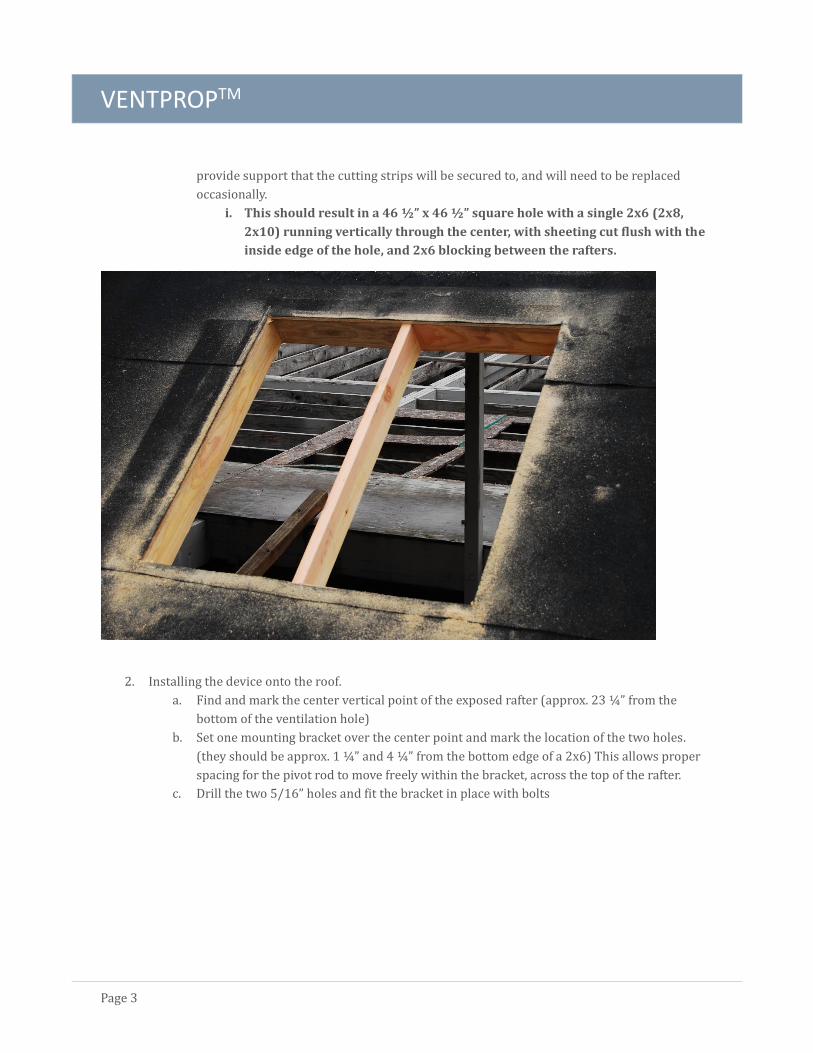
i. This should result in a 46 ½” x 46 ½” square hole with a single 2x6 (2x8,
2x10) running vertically through the center, with sheeting cut flush with the
inside edge of the hole, and 2x6 blocking between the rafters.
2. Installing the device onto the roof.
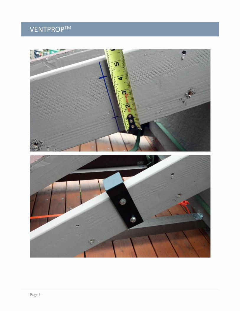
a. Find and mark the center vertical point of the exposed rafter (approx. 23 ¼” from the
bottom of the ventilation hole)
b. Set one mounting bracket over the center point and mark the location of the two holes.
(they should be approx. 1 ¼” and 4 ¼” from the bottom edge of a 2x6) This allows proper
spacing for the pivot rod to move freely within the bracket, across the top of the rafter.
c. Drill the two 5/16” holes and fit the bracket in place with bolts
VENTPROPTM
Page 4
VENTPROPTM
Page 5
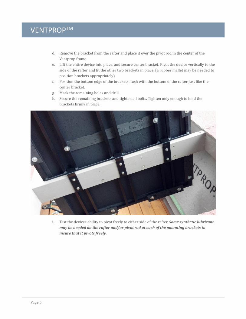
d. Remove the bracket from the rafter and place it over the pivot rod in the center of the
Ventprop frame.
e. Lift the entire device into place, and secure center bracket. Pivot the device vertically to the
side of the rafter and fit the other two brackets in place. (a rubber mallet may be needed to
position brackets appropriately)
f. Position the bottom edge of the brackets flush with the bottom of the rafter just like the
center bracket.
g. Mark the remaining holes and drill.
h. Secure the remaining brackets and tighten all bolts. Tighten only enough to hold the
brackets firmly in place.
i. Test the devices ability to pivot freely to either side of the rafter. Some synthetic lubricant
may be needed on the rafter and/or pivot rod at each of the mounting brackets to
insure that it pivots freely.
VENTPROPTM
Page 6
Operation
PREPARING THE PROP FOR USE
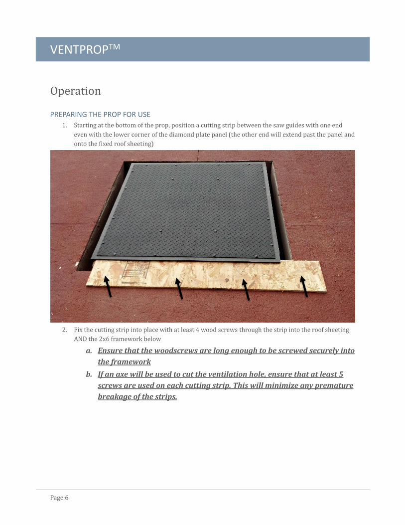
1. Starting at the bottom of the prop, position a cutting strip between the saw guides with one end
even with the lower corner of the diamond plate panel (the other end will extend past the panel and
onto the fixed roof sheeting)
2. Fix the cutting strip into place with at least 4 wood screws through the strip into the roof sheeting
AND the 2x6 framework below
a. Ensure that the woodscrews are long enough to be screwed securely into
the framework
b. If an axe will be used to cut the ventilation hole, ensure that at least 5
screws are used on each cutting strip. This will minimize any premature
breakage of the strips.
VENTPROPTM
Page 7
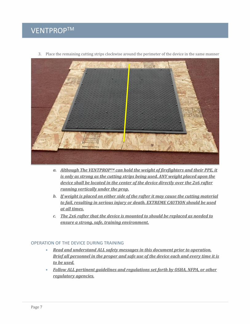
3. Place the remaining cutting strips clockwise around the perimeter of the device in the same manner
a. Although The VENTPROPTM can hold the weight of firefighters and their PPE, it
is only as strong as the cutting strips being used. ANY weight placed upon the
device shall be located in the center of the device directly over the 2x6 rafter
running vertically under the prop.
b. If weight is placed on either side of the rafter it may cause the cutting material
to fail, resulting in serious injury or death. EXTREME CAUTION should be used
at all times.
c. The 2x6 rafter that the device is mounted to should be replaced as needed to
ensure a strong, safe, training environment.
OPERATION OF THE DEVICE DURING TRAINING
• Read and understand ALL safety messages in this document prior to operation.
Brief all personnel in the proper and safe use of the device each and every time it is
to be used.
• Follow ALL pertinent guidelines and regulations set forth by OSHA, NFPA, or other
regulatory agencies.
VENTPROPTM
Page 8
• ALL training shall be supervised by properly certified fire instructors with
experience in vertical ventilation and roof operations.
Always follow the steps for access and ventilation as stated in your agency’s Standard Operating Guidelines
(SOGs/SOPs)
The following steps are not meant to be complete, or to cover all training for vertical ventilation.
1. Access the roof using ladders as needed, secure a roof ladder next to the device leaving enough
space between the ladder and the device to cut the hole
2. Place an appropriate tool in the roof section below the device for a foothold
a. If any weight is placed directly on the device, ensure it is placed directly
over the center rafter running vertically underneath the device.
3. Begin cutting the ventilation hole at the farthest, uppermost corner of the device and cutting
down to the lower corner
4. Return to the farthest, uppermost corner and cut the top strip toward the ladder
5. Cut from the farthest, lower corner toward the ladder
a. Be aware that the device is only held in place by one strip now, and is very
unstable. NO WEIGHT SHOULD BE PLACED INSIDE THE CUTTING AREA.
6. Cut the remaining strip from top to bottom while standing on the ladder
7. Using the appropriate tool pivot the device to the side of the rafter
Simulate removal of any ceiling material
RESTORING THE PROP FOR NEXT EVOLUTION
Always restore the prop when training is complete. The prop should be secured parallel with
roof surface any time it is not in use.
Materials needed:
Four disposable cutting strips at least 5 ½” x 44 ½” (when using OSB or plywood strips, we
recommend using 8” or wider strips. This will provide better support, and will allow you to
reverse the strips for a second evolution.
2 ½´ exterior grade wood screws (minimum of 16)
Cordless driver or impact driver
Follow the steps on page #6 for preparing the prop for use.
VENTPROPTM
Page 9
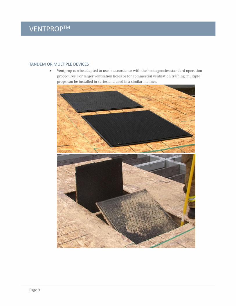
TANDEM OR MULTIPLE DEVICES
Ventprop can be adapted to use in accordance with the host agencies standard operation
procedures. For larger ventilation holes or for commercial ventilation training, multiple
props can be installed in series and used in a similar manner.
VENTPROPTM
Page 10
Maintenance
CLEANING AND INSPECTING
The device should be cleaned and inspected after every use. Typically, loose material and
saw dust can be removed with a small diameter hose and clean water. More thorough
cleaning can be done with warm soapy water and a soft brush.
Each part should be inspected for damage, especially around the perimeter of the device
where saws and /or axes are used.
o The saw guides are meant to be replaced as needed, however minor damage to the
guides should not affect the operation of the prop.
ANY damage to the metal frame or brackets requires proper repair before
continuing use. Contact CB2 Industries for information on repairs or replacement
If the prop is not pivoting smoothly to either side of the rafter, lubricate the pivot rod at
each bracket and between the pivot rod and the rafter. A clear silicone spray lubricant
works best.
REPLACEMENT OF SAW GUIDES
Saw guides are designed for multiple uses and only need to be replaced periodically. They
can be removed by simply removing the 4 bolts that hold them in, and sliding them from
between the diamond plate panel and the frame. The guides can be turned over and
reinstalled revealing a new, undamaged edge. After reversing the guides once, the guides
should be replaced as needed.
REPAIR
Repair of minor scratches or nicks in the powder coated finish can be done with black
enamel paint. This should be done periodically to protect the aluminum from corrosion
Larger gouges or cuts may need to be repaired by a qualified aluminum fabrication shop or
replaced. Please contact CB2 Industries with questions.
VENTPROPTM
Page 11
Safety
PERSONAL PROTECTIVE EQUIPMENT (PPE)
Each training agency is responsible for providing appropriate PPE for every individual using or operating
around the device (including instructors). ALL pertinent local and federal safety regulations shall be
followed. Typical equipment needed should include, but is not limited to:
Hearing protection
Helmet, bunker pants, jacket, and boots that meet current NFPA standards
Eye protection (goggles, face mask, or SCBA mask)
Chain saw chaps and/or other protective clothing/equipment required for operating
chainsaws.
FALL PROTECTION
Due to the nature of this training, Firefighters must be able to work on steep pitch roofs while elevated
above the ground level. Each district must evaluate the need and required fall protection to have in place
prior to training. OSHA and other occupational safety groups should be contacted for appropriate
guidelines.
EXHAUSTION AND REHAB
Increased physical activity with saws and other fire ground tools places personnel at greater risk for injury.
Each department should be actively monitoring personnel for signs of physical stress during training.
Especially during extreme hot or cold weather. Personnel should be reminded to drink plenty of fluids and
rehab as needed. Medical personnel should be on standby and each member should be trained in the local
rehab plan.
TRAINING
Instructors should be qualified in accordance with any state or national standards that are recognized by the
host agency. They should be experienced in the training of personnel, ladders, saw use, roof operations, and
vertical ventilation.
VENTPROPTM
Page 12
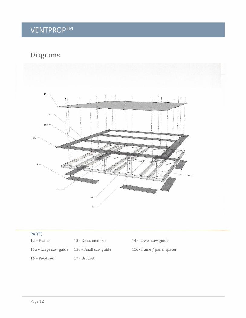
Diagrams
PARTS
12 – Frame 13 - Cross member 14 - Lower saw guide
15a – Large saw guide 15b - Small saw guide 15c - frame / panel spacer
16 – Pivot rod 17 - Bracket

VENTPROPTM
Page 13
Replacement Parts
Parts can be ordered by contacting CB2 Industries. Please have parts numbers and quantity needed
when calling or emailing.
Company Information
PO Box 71, Vernonia, Oregon 97064
Tel 503-475-4378
www.ventprop.com
email: [email protected]
Version 1.14

VENTPROPTM
Page 14


![Direct Methods for Solving Linear Systems [0.125in]3 ...mamu/courses/231/Slides/CH06_2A.pdf · Motivation Partial Pivoting Scaled Partial Pivoting Outline 1 Why Pivoting May be Necessary](https://img.dokumen.tips/doc/110x75/5ab8ef507f8b9aa6018d3c00/direct-methods-for-solving-linear-systems-0125in3-mamucourses231slidesch062apdfmotivation.jpg)