Embed Size (px)
Citation preview
Instruction manual Manuale di istruzioni
Ver. 1.0 DIS151
Serial number/numero di serie
Date of purchase/data di acquisto
Retailer/fornitore
Address/indirizzo
Suburb/cap/città
Capital city/provincial
State/stato
Tel./fax
Please note in the space provided above the relative service information of the model and the retailer from whom you purchased your Reflection LEDko P : this information will assist us in providing spare parts, repairs or in answering any technical enquiries with the utmost speed and accuracy.
Prendete nota, nello spazio apposite, dei dati relative al modello e al rivenditore del vostro Reflection LEDko P questi dati ci permetteranno di assistervi con la massima rapidità e precisione.
WARNING: the security of the fixture is granted only if these instructions are strictly followed; therefore it is absolutely necessary to keep this manual.
ATTENZIONE: la sicurezza dell’apparecchio è garantita solo con l’uso appropriato delle presenti istruzioni, pertanto è necessario conservarle.
User Manual Version 1.0 edition July, 2012
English
5
Index 1.Packaging and transportation ....................................................................................................................................................... 6
1.1 Packaging ................................................................................................................................................................................. 6 1.2 Trasportation ............................................................................................................................................................................. 6
2. General information ...................................................................................................................................................................... 6
2.1 Important safety information. ..................................................................................................................................................... 6 2.2 Warranty conditions .................................................................................................................................................................. 6 2.3 EC Norms ................................................................................................................................................................................. 6
3. Product specifications .................................................................................................................................................................. 7
3.1 Technical characteristics ........................................................................................................................................................... 7 3.2 Dimensions ............................................................................................................................................................................... 7 3.3 Unit’s main components ............................................................................................................................................................ 8 3.4 Rear panel, description ............................................................................................................................................................. 8
4. Installation ..................................................................................................................................................................................... 9
4.1 Optical installation ..................................................................................................................................................................... 9 4.2 Mechanical installation ............................................................................................................................................................ 10 4.3 Safety chain ............................................................................................................................................................................ 10 4.4 Adjusting unit’s tilt ................................................................................................................................................................... 10
5. Powering up ................................................................................................................................................................................. 11
5.1 Operating voltage and frequency. ........................................................................................................................................... 11 5.2 Connection to mains power ..................................................................................................................................................... 11
6. Control signal connections ........................................................................................................................................................ 12
6.1 Control signal connection by XLR5 plugs. ............................................................................................................................... 12 7. Turning on the projector ............................................................................................................................................................. 12
7.1 DMX address of the unit .......................................................................................................................................................... 12 7.2 DMX functions ......................................................................................................................................................................... 13
8. Display panel functions .............................................................................................................................................................. 14
8.1 Quick guide to menu ............................................................................................................................................................... 14 8.2 Rapid count ............................................................................................................................................................................. 14 8.3 Main function menu (FUNC) ................................................................................................................................................... 15 8.4 Measures and test s(MEAS) ................................................................................................................................................... 16 8.5 User settings (MODE) ............................................................................................................................................................. 17 8.6 Connecting DR1 and DR1 Plus ............................................................................................................................................... 17 8.7 Electronic alignment of the leds. ............................................................................................................................................. 17
9. Error messages ........................................................................................................................................................................... 19
10.Accessories and spare parts ..................................................................................................................................................... 19
11. Maintenance ............................................................................................................................................................................... 20
11.1 Periodic cleaning ................................................................................................................................................................... 20 11.2 Periodic controls.................................................................................................................................................................... 20 11.3 Fuses: ................................................................................................................................................................................... 20
12. F.A.Q. and answers ................................................................................................................................................................... 20
English
6
Thank you for having purchased a Coemar product. You have assured yourself of a fixture of the highest quality, both in the componentry and in the technology used. We renew our invitation to you to complete the service information form on the previous page. This will assist in providing prompt and accurate advice from your Coemar service centre, which you can thoroughly trust and to which you can submit any requests for service or information. Following the instructions and procedures outlined in this manual will ensure the maximum efficiency of this product for years to come.
1.Packaging and transportation 1.1 Packaging Open the packaging and make sure that no part of the equipment has suffered any damage during the transportation. In case of damage to the fixture, contact your currier and your supplier immediately by telephone, fax or email, and inform them you will formally notify them in writing through registered letter. Packing List Make sure the packaging contains: 1 Reflection LEDko P 2 This instruction manual. 3-main power plugs
1.2 Trasportation Reflection LEDko P must be transported exclusively in its original packaging or in an appropriate flight case.
2. General information 2.1 Important safety information. Fire prevention: 1.Never locate the fixture on any flammable surface. 2.Minimum distance from flammable materials: 0,5m. 3.Minimum distance from the closet illuminable surface: 0,5m. 4. Connect the projector to mains power protected by a thermal magnetic circuit breaker.
Preventing from electric shock. 1. Presence of high voltage inside of the fixture. Insulate the projector from mains supply before opening or performing any function which involves touching the inside of the fixture, including lamp replacement.. 2. For the connection to the mains, adhere strictly to the guidelines outlined in this manual. 3. The level of technology of Reflection LEDko P requires the use of specialised personnel for all service applications; refer all work to your authorised Coemar service centre. 4. A good earth connection is essential for the proper functioning of the projector. Never connect the fixture if there is no earth connection. 5.Mains cables must not come into contact with other cables. 6.Do not operate the projector with wet hands or in an area where water is present. 7.The fixture must never be located in an exposed position, or in areas of extreme humidity.
Safety. 1. The projector must always be installed with bolts, clamps, or other fixing devices which are suitably rated to support the weight of the projector. 2. Always use a secondary safety fixing device with chain or steel wire of a suitable rating to sustain the weight of the unit in case of failure of the principal fixing point. 3. The external surfaces of the unit, at various points, may reach 60°C. Never handle the unit until at least 10 minutes have elapsed since the lamp was turned off 4. Never install the fixture in an enclosed area lacking sufficient air flow; the room temperature must not exceed 35°C. 5. The projector contains electronic and electrical components which must under no circumstances be in contact with water, oil or any other liquid. Failure to do so will compromise the proper functioning of the projector.
2.2 Warranty conditions 1. The fixture is guaranteed for a period of 12 months from the date of purchase against manufacturing or materials defects. 2. The warranty does not extend to damage caused by inappropriate usage, use by inexperienced operators or inadequate maintenance. 3. The warranty is immediately void if the projector has been tampered or opened by unauthorized personnel. 4. The warranty does not extend to fixture replacement. 5. Both the serial number and the model of the projector are required for any advice or service from your authorised service centre.
2.3 EC Norms The projector meets all fundamental applicable EC requirements.
English
7
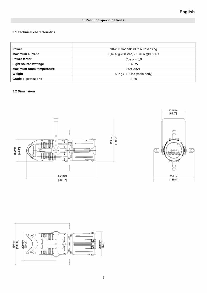
3. Product specifications
3.1 Technical characteristics
Power
90-250 Vac 50/60Hz Autosensing Maximum current 0,67A @230 Vac, - 1,76 A @90VAC
Power factor Cos ϕ = 0,9 Light source wattage 140 W
Maximum room temperature 35°C/95°F Weight 5 Kg./11.2 lbs (main body) Grado di protezione IP20
3.2 Dimensions
English
8
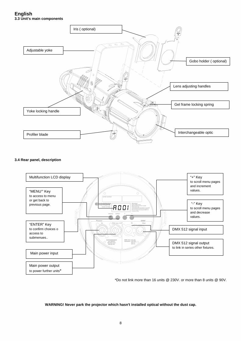
3.3 Unit’s main components
3.4 Rear panel, description
*Do not link more than 16 units @ 230V. or more than 8 units @ 90V.
WARNING! Never park the projector which hasn't installed optical without the dust cap.
Adjustable yoke
Iris ( optional)
Gobo holder ( optional)
Yoke locking handle
Interchangeable optic Profiler blade
Gel frame locking spring
Lens adjusting handles
Multifunction LCD display
“MENU’” Key to access to menu or get back to previous page.
“ENTER” Key to confirm choices o access to submenues..
“+” Key to scroll menu pages and increment values.
“-” Key to scroll menu pages and decrease values.
Main power input
Main power output to power further units*
DMX 512 signal input
DMX 512 signal output to link in series other fixtures.
English
9
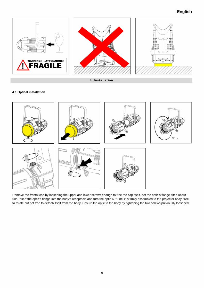
4. Installation
4.1 Optical installation
Remove the frontal cap by loosening the upper and lower screws enough to free the cap itself, set the optic’s flange tilted about 60°. Insert the optic’s flange into the body’s receptacle and turn the optic 60° until it is firmly assembled to the projector body, free to rotate but not free to detach itself from the body. Ensure the optic to the body by tightening the two screws previously loosened.
English
10
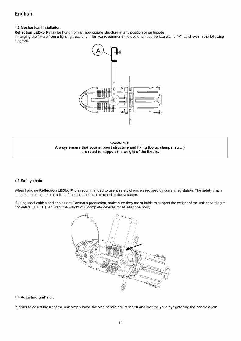
4.2 Mechanical installation Reflection LEDko P may be hung from an appropriate structure in any position or on tripode. If hanging the fixture from a lighting truss or similar, we recommend the use of an appropriate clamp “A”, as shown in the following diagram.
WARNING!
Always ensure that your support structure and fixing (bolts, clamps, etc…) are rated to support the weight of the fixture.
4.3 Safety chain When hanging Reflection LEDko P it is recommended to use a safety chain, as required by current legislation. The safety chain must pass through the handles of the unit and then attached to the structure.
If using steel cables and chains not Coemar's production, make sure they are suitable to support the weight of the unit according to normative UL/ETL ( required: the weight of 6 complete devices for at least one hour)
4.4 Adjusting unit’s tilt In order to adjust the tilt of the unit simply loose the side handle adjust the tilt and lock the yoke by tightening the handle again.
A
English
11
5. Powering up
5.1 Operating voltage and frequency. The unit may operates at voltages ranges from 90 to 250VaC at a frequency of 50 or 60 Hz. It is not needed to effect any setup procedures: Reflection LEDko P will automatically adjust its operation to suit any frequency or voltage within this range.
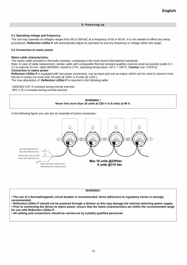
5.2 Connection to mains power Mains cable characteristics The mains cable provided is thermally resistant, complying to the most recent International standards. Note: in case of cable replacement, similar cable with comparable thermal resistant qualities must be used exclusively (cable 3 X 1,5 ø external 10 mm, rated 300/500V, tested to 2 KV, operating temperature -40°C + 180°C, Coemar cod. CV5311). Connection to mains power Reflection LEDko P is equipped with two power connectors, one as input and one as output, which can be used to connect more fixtures in series (no more than 16 units @ 230V or 8 units @ 115V.). The max absorption of Reflection LEDko P is reported in the following table:
-230/240V 0,67 A constant during normal exercise. -90V 1,76 A constant during normal exercise.
WARNING ! Never link more than 16 units at 230 V or 8 units at 90 V.
In the following figure you can see an example of series connection:
WARNING!
• The use of a thermal/magnetic circuit breaker is recommended. Strict adherence to regulatory norms is strongly recommended. • Reflection LEDko P should not be powered through a dimmer as this may damage the internal switching power supply. • Prior to connecting the device to mains power, ensure that the mains characteristics are within the recommended range for use with Reflection LEDko P. • All cabling and connections should be carried out by suitably qualified personnel.
Blu (CE) / Bianco(UL-ETL)
Blue (CE) / White (UL-ETL)
Marrone (CE) / Nero (UL-ETL)
Brown (CE) / Black (UL-ETL)
Giallo verde (CE) / Verde (UL-ETL)
Green yellow (CE) / Green (UL-ETL)
English
12
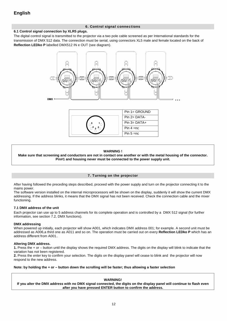
6. Control signal connections 6.1 Control signal connection by XLR5 plugs. The digital control signal is transmitted to the projector via a two pole cable screened as per International standards for the transmission of DMX 512 data. The connection must be serial, using connectors XL5 male and female located on the back of Reflection LEDko P labelled DMX512 IN e OUT (see diagram).
Pin 1= GROUND Pin 2= DATA- Pin 3= DATA+
Pin 4 =nc Pin 5 =nc
WARNING ! Make sure that screening and conductors are not in contact one another or with the metal housing of the connector.
Pin#1 and housing never must be connected to the power supply unit.
7. Turning on the projector After having followed the preceding steps described, proceed with the power supply and turn on the projector connecting it to the mains power. The software version installed on the internal microprocessors will be shown on the display, suddenly it will show the current DMX addressing. If the address blinks, it means that the DMX signal has not been received. Check the connection cable and the mixer functioning.
7.1 DMX address of the unit Each projector can use up to 5 address channels for its complete operation and is controlled by a DMX 512 signal (for further information, see section 7.2, DMX functions).
DMX addressing When powered up initially, each projector will show A001, which indicates DMX address 001; for example. A second unit must be addressed as A006,a third one as A011 and so on. The operation must be carried out on every Reflection LEDko P which has an address different from A001..
Altering DMX address. 1. Press the + or – button until the display shows the required DMX address. The digits on the display will blink to indicate that the variation has not been registered. 2. Press the enter key to confirm your selection. The digits on the display panel will cease to blink and the projector will now respond to the new address.
Note: by holding the + or – button down the scrolling will be faster; thus allowing a faster selection
WARNING! If you alter the DMX address with no DMX signal connected, the digits on the display panel will continue to flash even
after you have pressed ENTER button to confirm the address.
English
13
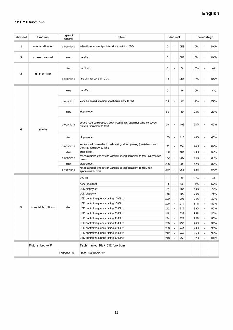
7.2 DMX functions
c hanneltype of c ontrol
1 proportional 0 - 255 0% - 100%
2 step 0 - 255 0% - 100%
step 0 - 9 0% - 4%
proportional 10 - 255 4% - 100%
step 0 - 9 0% - 4%
proportional 10 - 57 4% - 22%
step 58 - 59 23% - 23%
proportional 60 - 108 24% - 42%
step 109 - 110 43% - 43%
proportional 111 - 159 44% - 62%
step 160 - 161 63% - 63%
proportional 162 - 207 64% - 81%
step 208 - 209 82% - 82%
proportional 210 - 255 82% - 100%
0 - 9 0% - 4%
10 - 133 4% - 52%
134 - 185 53% - 73%
186 - 199 73% - 78%
200 - 205 78% - 80%
206 - 211 81% - 83%
212 - 217 83% - 85%
218 - 223 85% - 87%
224 - 229 88% - 90%
230 - 235 90% - 92%
236 - 241 93% - 95%
242 - 247 95% - 97%
248 - 255 97% - 100%
Edizione: 0
LED control frequency tuning 4500Hz
LED control frequency tuning 5000Hz
Fixture: Ledk o P Table name: DMX 512 func tions
Data: 03/ 05/ 2012
LED control frequency tuning 1500Hz
LED control frequency tuning 2000Hz
LED control frequency tuning 2500Hz
LED control frequency tuning 3000Hz
LED control frequency tuning 3500Hz
LED control frequency tuning 4000Hz
stop strobe
random strobe effect with variable speed from slow to fast, non syncronised colors.
5 spec ial func tions step
600 Hz
park, no effect
LCD display off
LCD display on
LED control frequency tuning 1000Hz
4 strobe
no effect
variable speed strobing effect, from slow to fast
stop strobe
sequenced pulse effect, slow closing, fast opening( variable speed pulsing, from slow to fast)
stop strobe
sequenced pulse effect, fast closing, slow opening ( variable speed pulsing, from slow to fast)
stop strobe
random strobe effect with variable speed from slow to fast, syncronised colors.
spare c hannel no effect
3 dimmer f ine
no effect
fine dimmer control 16 bit.
func tion effec t dec imal perc entage
master dimmer adjust luminous output intensity from 0 to 100%
English
14
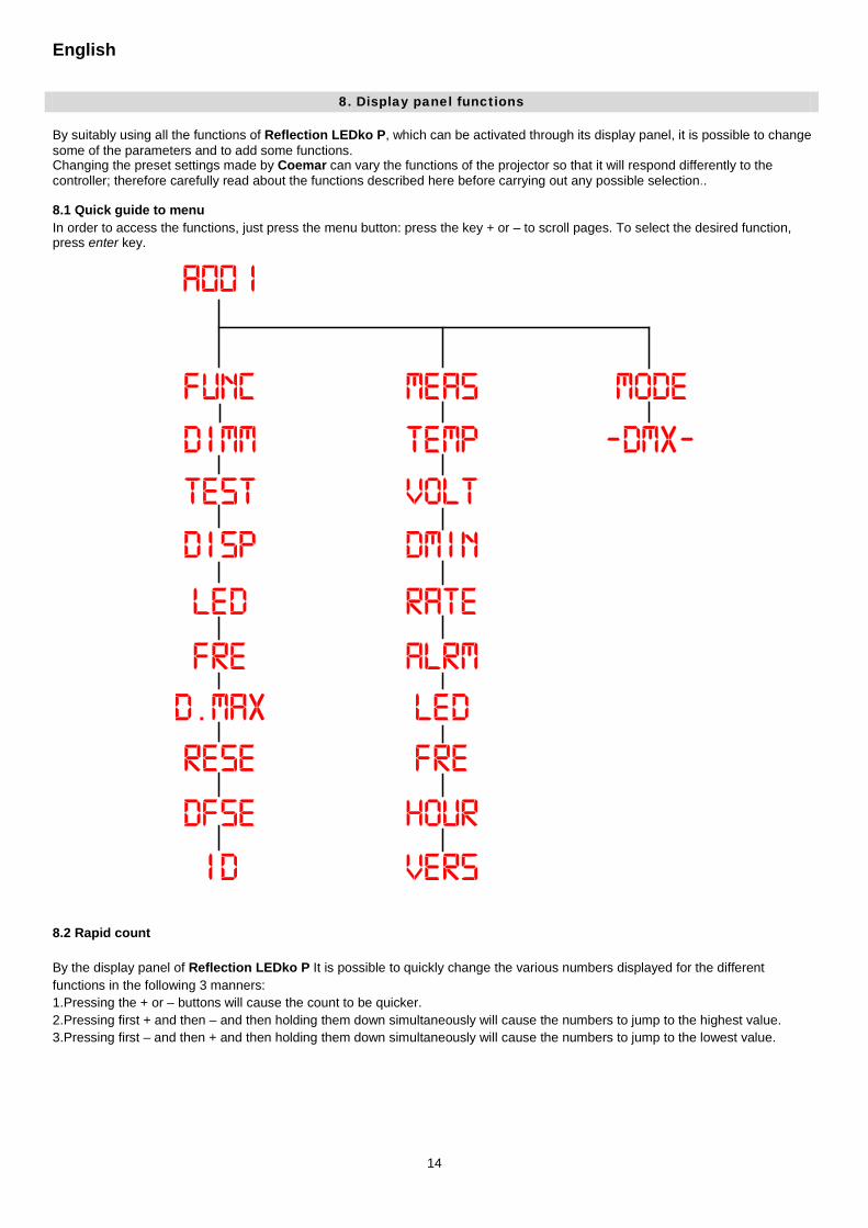
8. Display panel functions By suitably using all the functions of Reflection LEDko P, which can be activated through its display panel, it is possible to change some of the parameters and to add some functions. Changing the preset settings made by Coemar can vary the functions of the projector so that it will respond differently to the controller; therefore carefully read about the functions described here before carrying out any possible selection..
8.1 Quick guide to menu In order to access the functions, just press the menu button: press the key + or – to scroll pages. To select the desired function, press enter key.
8.2 Rapid count By the display panel of Reflection LEDko P It is possible to quickly change the various numbers displayed for the different functions in the following 3 manners: 1.Pressing the + or – buttons will cause the count to be quicker. 2.Pressing first + and then – and then holding them down simultaneously will cause the numbers to jump to the highest value. 3.Pressing first – and then + and then holding them down simultaneously will cause the numbers to jump to the lowest value.
English
15
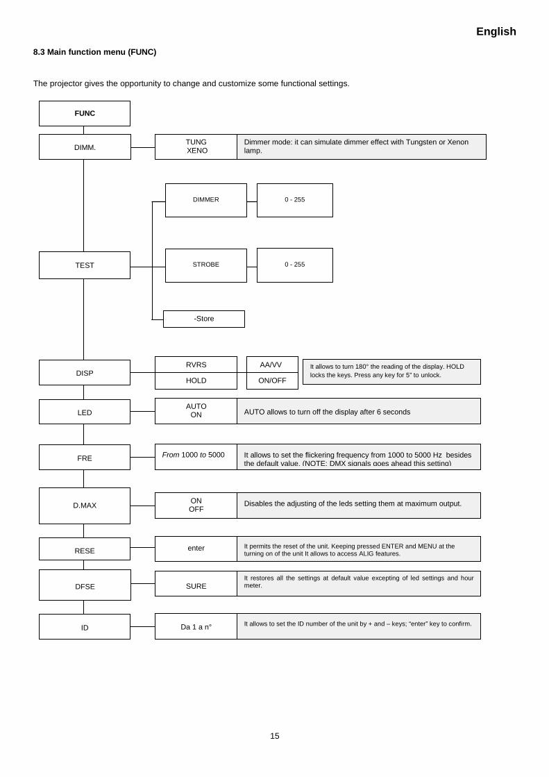
8.3 Main function menu (FUNC)
The projector gives the opportunity to change and customize some functional settings.
FUNC
DIMM.
Dimmer mode: it can simulate dimmer effect with Tungsten or Xenon lamp.
TUNG XENO
ID
It allows to set the ID number of the unit by + and – keys; “enter” key to confirm.
Da 1 a n°
TEST
DISP It allows to turn 180° the reading of the display. HOLD locks the keys. Press any key for 5” to unlock.
RVRS
HOLD
AA/VV
ON/OFF
-Store
DIMMER
STROBE
0 - 255
0 - 255
D.MAX
RESE
DFSE
Disables the adjusting of the leds setting them at maximum output.
It permits the reset of the unit. Keeping pressed ENTER and MENU at the turning on of the unit It allows to access ALIG features.
It restores all the settings at default value excepting of led settings and hour meter.
ON OFF
enter
SURE
LED AUTO allows to turn off the display after 6 seconds AUTO
ON
FRE It allows to set the flickering frequency from 1000 to 5000 Hz besides the default value. (NOTE: DMX signals goes ahead this setting)
From 1000 to 5000
English
16
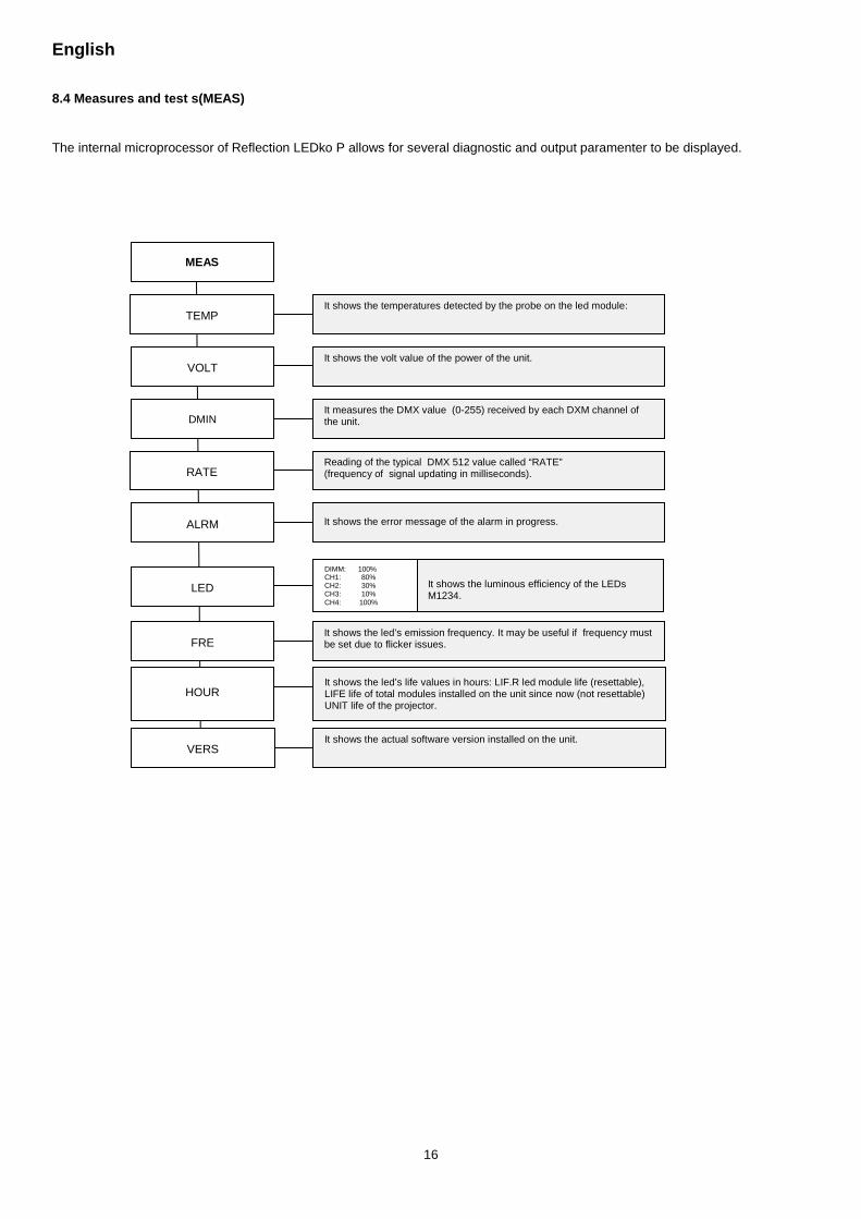
8.4 Measures and test s(MEAS)
The internal microprocessor of Reflection LEDko P allows for several diagnostic and output paramenter to be displayed.
MEAS
It shows the temperatures detected by the probe on the led module:
It shows the volt value of the power of the unit.
It measures the DMX value (0-255) received by each DXM channel of the unit.
Reading of the typical DMX 512 value called “RATE” (frequency of signal updating in milliseconds).
It shows the error message of the alarm in progress.
It shows the luminous efficiency of the LEDs M1234.
It shows the led’s life values in hours: LIF.R led module life (resettable), LIFE life of total modules installed on the unit since now (not resettable) UNIT life of the projector.
It shows the led’s emission frequency. It may be useful if frequency must be set due to flicker issues.
TEMP
VOLT
DMIN
RATE
ALRM
LED
HOUR
FRE
DIMM: 100% CH1: 80% CH2: 30% CH3: 10% CH4: 100%
It shows the actual software version installed on the unit. VERS
English
17
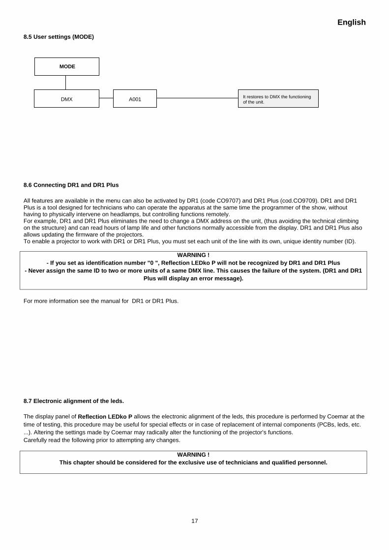
8.5 User settings (MODE)
8.6 Connecting DR1 and DR1 Plus All features are available in the menu can also be activated by DR1 (code CO9707) and DR1 Plus (cod.CO9709). DR1 and DR1 Plus is a tool designed for technicians who can operate the apparatus at the same time the programmer of the show, without having to physically intervene on headlamps, but controlling functions remotely. For example, DR1 and DR1 Plus eliminates the need to change a DMX address on the unit, (thus avoiding the technical climbing on the structure) and can read hours of lamp life and other functions normally accessible from the display. DR1 and DR1 Plus also allows updating the firmware of the projectors. To enable a projector to work with DR1 or DR1 Plus, you must set each unit of the line with its own, unique identity number (ID).
WARNING ! - If you set as identification number "0 ", Reflection LEDko P will not be recognized by DR1 and DR1 Plus
- Never assign the same ID to two or more units of a same DMX line. This causes the failure of the system. (DR1 and DR1 Plus will display an error message).
For more information see the manual for DR1 or DR1 Plus.
8.7 Electronic alignment of the leds. The display panel of Reflection LEDko P allows the electronic alignment of the leds, this procedure is performed by Coemar at the time of testing, this procedure may be useful for special effects or in case of replacement of internal components (PCBs, leds, etc. ...). Altering the settings made by Coemar may radically alter the functioning of the projector’s functions. Carefully read the following prior to attempting any changes.
WARNING ! This chapter should be considered for the exclusive use of technicians and qualified personnel.
MODE
DMX It restores to DMX the functioning of the unit. A001
English
18
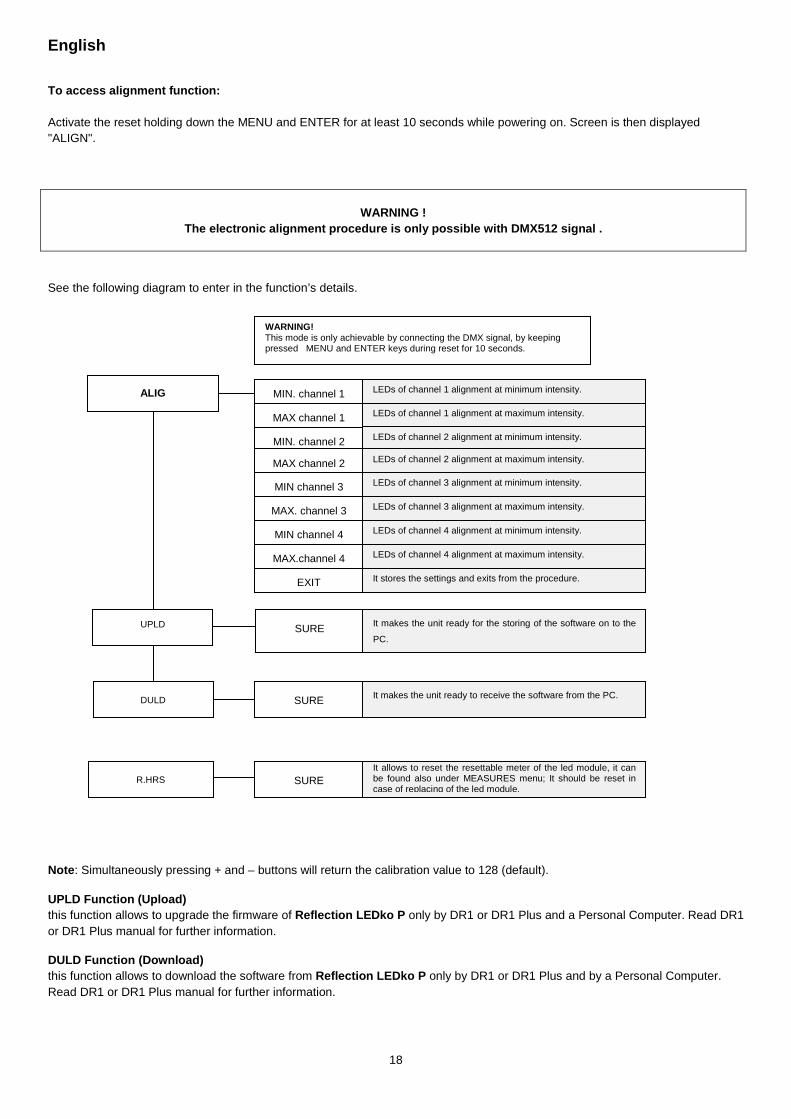
To access alignment function: Activate the reset holding down the MENU and ENTER for at least 10 seconds while powering on. Screen is then displayed "ALIGN".
WARNING ! The electronic alignment procedure is only possible with DMX512 signal .
See the following diagram to enter in the function’s details.
Note: Simultaneously pressing + and – buttons will return the calibration value to 128 (default).
UPLD Function (Upload) this function allows to upgrade the firmware of Reflection LEDko P only by DR1 or DR1 Plus and a Personal Computer. Read DR1 or DR1 Plus manual for further information.
DULD Function (Download) this function allows to download the software from Reflection LEDko P only by DR1 or DR1 Plus and by a Personal Computer. Read DR1 or DR1 Plus manual for further information.
ALIG
WARNING! This mode is only achievable by connecting the DMX signal, by keeping pressed MENU and ENTER keys during reset for 10 seconds.
MIN. channel 1
MAX channel 1
MIN. channel 2
MAX channel 2
MIN channel 3
MAX. channel 3
MAX.channel 4
MIN channel 4
LEDs of channel 1 alignment at minimum intensity.
LEDs of channel 1 alignment at maximum intensity.
LEDs of channel 2 alignment at minimum intensity.
LEDs of channel 2 alignment at maximum intensity.
LEDs of channel 3 alignment at minimum intensity.
LEDs of channel 3 alignment at maximum intensity.
LEDs of channel 4 alignment at minimum intensity.
LEDs of channel 4 alignment at maximum intensity.
SURE It allows to reset the resettable meter of the led module, it can be found also under MEASURES menu; It should be reset in case of replacing of the led module.
R.HRS
SURE
SURE
It makes the unit ready to receive the software from the PC.
It makes the unit ready for the storing of the software on to the
PC.
DULD
UPLD
EXIT It stores the settings and exits from the procedure.
English
19
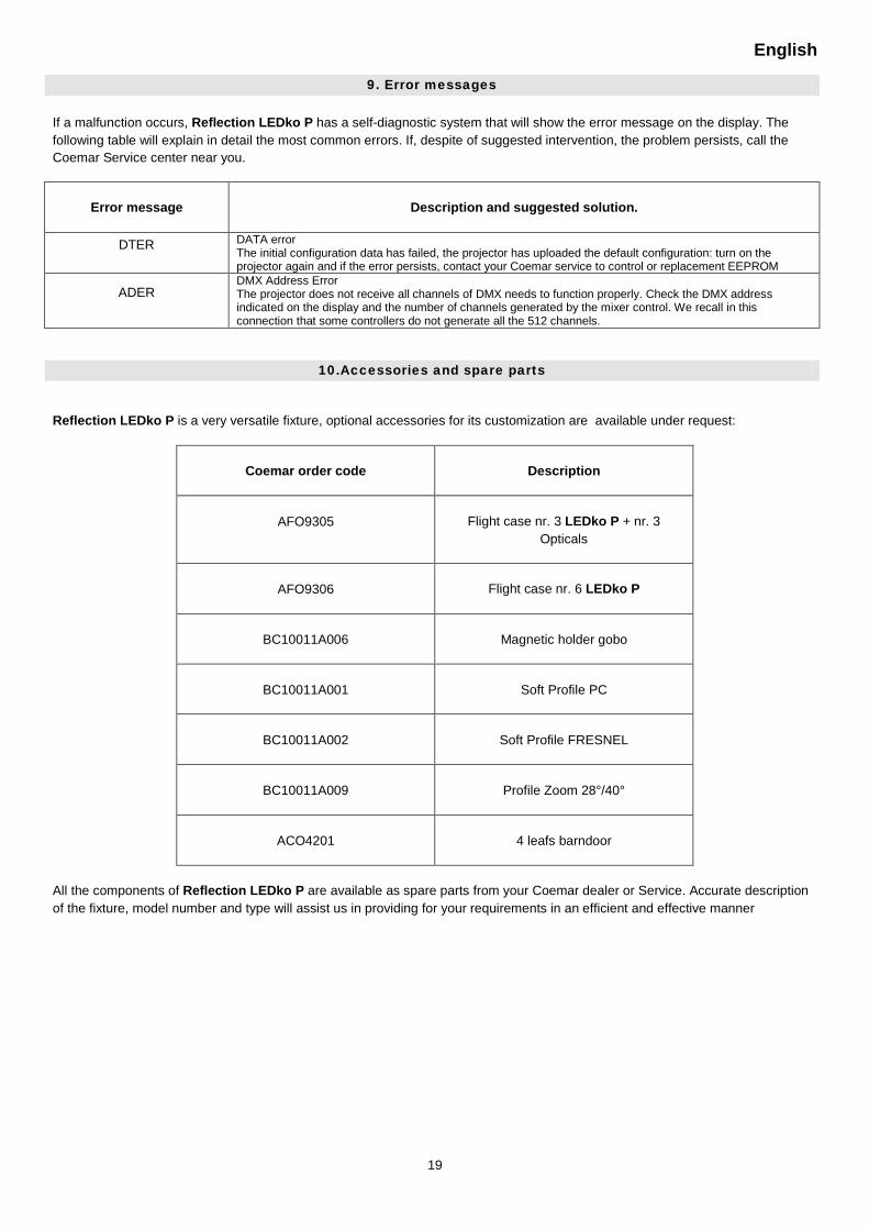
9. Error messages If a malfunction occurs, Reflection LEDko P has a self-diagnostic system that will show the error message on the display. The following table will explain in detail the most common errors. If, despite of suggested intervention, the problem persists, call the Coemar Service center near you.
Error message
Description and suggested solution.
DTER DATA error The initial configuration data has failed, the projector has uploaded the default configuration: turn on the projector again and if the error persists, contact your Coemar service to control or replacement EEPROM
ADER DMX Address Error The projector does not receive all channels of DMX needs to function properly. Check the DMX address indicated on the display and the number of channels generated by the mixer control. We recall in this connection that some controllers do not generate all the 512 channels.
10.Accessories and spare parts
Reflection LEDko P is a very versatile fixture, optional accessories for its customization are available under request:
Coemar order code Description
AFO9305 Flight case nr. 3 LEDko P + nr. 3 Opticals
AFO9306 Flight case nr. 6 LEDko P
BC10011A006 Magnetic holder gobo
BC10011A001 Soft Profile PC
BC10011A002 Soft Profile FRESNEL
BC10011A009 Profile Zoom 28°/40°
ACO4201 4 leafs barndoor
All the components of Reflection LEDko P are available as spare parts from your Coemar dealer or Service. Accurate description of the fixture, model number and type will assist us in providing for your requirements in an efficient and effective manner
English
20
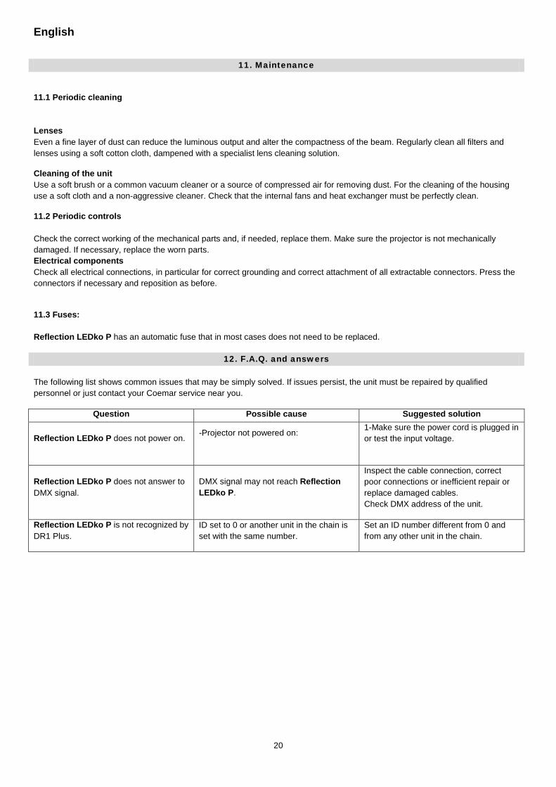
11. Maintenance
11.1 Periodic cleaning Lenses Even a fine layer of dust can reduce the luminous output and alter the compactness of the beam. Regularly clean all filters and lenses using a soft cotton cloth, dampened with a specialist lens cleaning solution.
Cleaning of the unit Use a soft brush or a common vacuum cleaner or a source of compressed air for removing dust. For the cleaning of the housing use a soft cloth and a non-aggressive cleaner. Check that the internal fans and heat exchanger must be perfectly clean.
11.2 Periodic controls Check the correct working of the mechanical parts and, if needed, replace them. Make sure the projector is not mechanically damaged. If necessary, replace the worn parts. Electrical components Check all electrical connections, in particular for correct grounding and correct attachment of all extractable connectors. Press the connectors if necessary and reposition as before.
11.3 Fuses: Reflection LEDko P has an automatic fuse that in most cases does not need to be replaced.
12. F.A.Q. and answers The following list shows common issues that may be simply solved. If issues persist, the unit must be repaired by qualified personnel or just contact your Coemar service near you.
Question Possible cause Suggested solution
Reflection LEDko P does not power on. -Projector not powered on:
1-Make sure the power cord is plugged in or test the input voltage.
Reflection LEDko P does not answer to DMX signal.
DMX signal may not reach Reflection LEDko P.
Inspect the cable connection, correct poor connections or inefficient repair or replace damaged cables. Check DMX address of the unit.
Reflection LEDko P is not recognized by DR1 Plus.
ID set to 0 or another unit in the chain is set with the same number.
Set an ID number different from 0 and from any other unit in the chain.
English
21
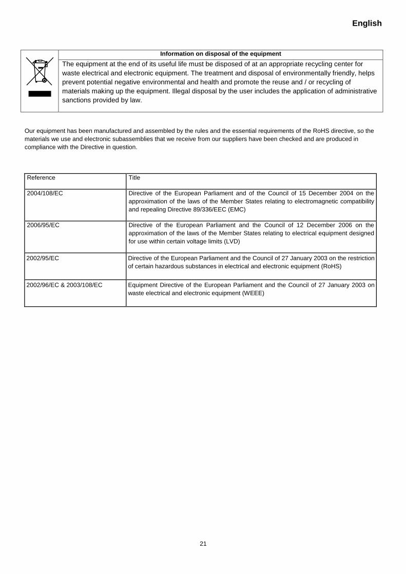
Information on disposal of the equipment
The equipment at the end of its useful life must be disposed of at an appropriate recycling center for waste electrical and electronic equipment. The treatment and disposal of environmentally friendly, helps prevent potential negative environmental and health and promote the reuse and / or recycling of materials making up the equipment. Illegal disposal by the user includes the application of administrative sanctions provided by law.
Our equipment has been manufactured and assembled by the rules and the essential requirements of the RoHS directive, so the materials we use and electronic subassemblies that we receive from our suppliers have been checked and are produced in compliance with the Directive in question.
Reference Title
2004/108/EC Directive of the European Parliament and of the Council of 15 December 2004 on the approximation of the laws of the Member States relating to electromagnetic compatibility and repealing Directive 89/336/EEC (EMC)
2006/95/EC Directive of the European Parliament and the Council of 12 December 2006 on the approximation of the laws of the Member States relating to electrical equipment designed for use within certain voltage limits (LVD)
2002/95/EC Directive of the European Parliament and the Council of 27 January 2003 on the restriction of certain hazardous substances in electrical and electronic equipment (RoHS)
2002/96/EC & 2003/108/EC Equipment Directive of the European Parliament and the Council of 27 January 2003 on waste electrical and electronic equipment (WEEE)

Coemar s.p.a.
via Inghilterra 2/A - 46042 Castel Goffredo (Mantova) Italyph. +39 0376/77521 - fax +39 0376/780657
Coemar si riserva il diritto di apportare modifiche senza preavviso.
Coemar reserves the right to effect modifications without notification