Embed Size (px)
Citation preview
6Installing,Configuring,Managing,Monitoring, andTroubleshootingNetwork ProtocolsCERTIFICATION OBJECTIVES
6.01 Windows 2000 TCP/IP
6.02 IP Addressing
6.03 Installing, Configuring, Managing, andMonitoring TCP/IP
6.04 Installing and Configuring NWLink
✓ Two-Minute Drill
Q&A Self Test
CertPrs8 / MCSE Windows® 2000 Network Administration Study Guide (Exam 70-216) / Syngress / 2383-4 / Chapter 6Blind Folio 6:387
CertPrs8 / MCSE Windows® 2000 Network Administration Study Guide (Exam 70-216) / Syngress / 2383-4 / Chapter 6Blind Folio 6:387
P:\010Comp\CertPrs8\383-4\ch06.vpFriday, June 30, 2000 1:06:13 PM
Color profile: Generic CMYK printer profileComposite Default screen
388 Chapter 6: Installing, Configuring, Managing, Monitoring, and Troubleshooting Network Protocols
CertPrs8 / MCSE Windows® 2000 Network Administration Study Guide (Exam 70-216) / Syngress / 2383-4 / Chapter 6
The Windows NT 4.0 certification track included an elective exam (taken by the vastmajority of MCSE candidates) on the intricacies of the TCP/IP protocol suite and itsimplementation in various network environments. The new Windows 2000 track does
not include an exam on this topic, which may lead some candidates to mistakenly believe that it isno longer necessary to study and understand TCP/IP. Nothing could be farther from the truth
IntroductionThere is a good reason for the fact that there is no TCP/IP elective in the Windows2000 MCSE track: a thorough knowledge and understanding of this set of protocolsis no longer optional. TCP/IP is the foundation upon which Windows 2000networking is built, and it is the default protocol stack installed with the operatingsystem. The components of the suite and how to use them will be integral topics inthe Windows 2000 core exams, especially Exam 70-216, “Implementing andAdministering a Windows 2000 Network Infrastructure.”
TCP/IP is not peculiar to Microsoft networks. In fact, not so long ago, TCP/IPwas regarded as a somewhat sluggish, difficult-to-configure protocol used primarilyby university or government networks participating in an exotic wide areanetworking project called ARPAnet. Few private organizations used it for theirLANS because it was considered too slow and complex.
There were other protocols available that seemed to offer many advantages overthe TCP/IP suite. Microsoft and IBM workgroups could use NetBEUI, a fast andsimple transport protocol that could be set up easily and quickly by someonewithout a great deal of expertise. Novell NetWare networks, prior to NetWare 5.0,required the IPX/SPX stack, which was routable and thus could be used with largerserver-based networks. Few business networks had any need for a powerful buthigh-overhead set of protocols like TCP/IP.
That was before the explosive popularity of the global wide area network we callthe Internet. Inexpensive and easy to implement instant worldwide connectivitychanged the lives of many people—and it changed the nature of networking. Thegrowth of the Internet, more than any other single phenomenon, was responsible forthe popularity enjoyed by TCP/IP in networking today. TCP/IP is the protocolstack on which the Internet runs.
In this chapter, we will focus primarily on the TCP/IP protocol suite. We’llbriefly discuss the history and evolution of TCP/IP, and the purposes of the variousprotocols included in the suite. We’ll pay particular attention to how to configureand use TCP/IP in a Windows 2000 network, and we’ll examine some commontroubleshooting scenarios.
P:\010Comp\CertPrs8\383-4\ch06.vpFriday, June 30, 2000 1:06:13 PM
Color profile: Generic CMYK printer profileComposite Default screen
Windows 2000 TCP/IP 389
CertPrs8 / MCSE Windows® 2000 Network Administration Study Guide (Exam 70-216) / Syngress / 2383-4 / Chapter 6
An important part of implementing and administering a TCP/IP-based networkis working with IP addressing issues, and we will delve into this topic in some depth.We will include information on IP subnetting and supernetting, and talk about newdevelopments on the TCP/IP front, such as Classless InterDomain Routing (CIDR)and IPv6, the future incarnation of the Internet Protocol.
Although TCP/IP is Microsoft’s obvious protocol of choice for Windows 2000local area networks, there are still many hybrid networks in existence, in whichWindows 2000 machines must coexist with current and older versions of NovellNetWare. Microsoft provides support for NWLink, its own implementation of theIPX/SPX protocol stack that is necessary for connection to NetWare networks priorto version 5. We will look briefly at how to install and configure the NWLinkprotocol, and discuss the importance of binding orders when running multipleprotocols on a Windows 2000 computer.
CERTIFICATION OBJECTIVE 6.01
Windows 2000 TCP/IPThe Transmission Control Protocol/Internet Protocol (TCP/IP) stack is often calledthe protocol of the Internet. It is also the protocol of choice for Windows 2000. TheWindows 2000 implementation of TCP/IP is based on industry standards anddesigned to support networks of all sizes, up to the largest enterprise environments,as well as providing connectivity to the Internet.
Windows 2000 TCP/IP also includes a variety of built-in utilities used toconfigure, maintain, and troubleshoot the protocols, and to provide connectivity tomany different types of systems, such as:
■ Internet host computers
■ Apple Macintosh systems
■ IBM mainframe systems
■ UNIX systems
■ Open VMS systems
■ Microsoft Windows NT and Windows 2000 computers
■ Microsoft Windows 95 and 98 computers
P:\010Comp\CertPrs8\383-4\ch06.vpFriday, June 30, 2000 1:06:13 PM
Color profile: Generic CMYK printer profileComposite Default screen
390 Chapter 6: Installing, Configuring, Managing, Monitoring, and Troubleshooting Network Protocols
CertPrs8 / MCSE Windows® 2000 Network Administration Study Guide (Exam 70-216) / Syngress / 2383-4 / Chapter 6
■ Microsoft Windows for Workgroups computers
■ Microsoft LAN Manager networks
■ Network-ready printers, such as HP JetDirect-equipped printers
Windows 2000 TCP/IP also includes utilities such as File Transfer Protocol(FTP) and Telnet. FTP is a character-based application protocol that allows youto connect to FTP servers and transfer files. Telnet is an application that allows youto log in to remote computers and issue commands as if you were sitting at thekeyboard of the remote computer. There are many variations of FTP, Telnet, andother programs based on earlier Internet standards available on the Internet asfreeware/shareware or for purchase from third-party vendors.
We will take a more detailed look at these utilities and how they are used, later inthis chapter.
Introduction to TCP/IPBefore we can understand the function of the TCP/IP protocols, we must firstunderstand the role of protocols in computing and computer networking. A protocolis sometimes likened to a language that computers “speak” to communicate withone another, but a better analogy would be to think of the protocol as the syntax ofa language. Protocols are sets of rules that specify the order and manner in whichprocesses occur (in this case, the elements of the network communications process).A common protocol is necessary for two computers to “understand” one another.
Although TCP/IP is often referred to as “a” LAN protocol, in reality it is a set ofprotocols, also called a protocol stack or protocol suite. A stack consists of two or moreprotocols working together to accomplish a purpose (communication with anothercomputer across a network). A suite is a more elaborate collection of communicationprotocols, utilities, tools, and applications. TCP and IP make up the stack, whichhandles the most important tasks of communication such as handling addressingand routing issues, error checking, and flow control. The suite includes a largenumber of additional protocols, used in various situations and for differentpurposes. Different vendors may include different tools and utilities in theirimplementations of the TCP/IP suite.
Some protocols that were developed specifically for the TCP/IP suite includeSimple Mail Transfer Protocol (SMTP), Simple Network ManagementProtocol (SNMP), and File Transfer Protocol (FTP).
P:\010Comp\CertPrs8\383-4\ch06.vpFriday, June 30, 2000 1:06:14 PM
Color profile: Generic CMYK printer profileComposite Default screen
TCP/IP is known as an open standard protocol. In other words, it does not“belong” to any specific vendor, but is open to implementation by differentcompanies. Thus we have not only Windows 2000 TCP/IP, but Novell’s TCP/IPstack, UNIX stacks, TCP/IP stacks that are designed to run on Macintosh systemsor mainframe computers, and so on. In order to maintain compatibility across thesedifferent operating systems and environments, all these vendors must adhere tocertain standards.
TCP/IP StandardsStandards and specifications relating to various aspects of the TCP/IP suite arepublished as RFCs (Requests for Comments) on the Internet and serve as guidelinesto promote standardization. The Windows 2000 implementation of MicrosoftTCP/IP supports a large number of RFCs that define how the protocols work.These documents are used to describe Internet standards, and go through a formalapproval process before being adopted.
Windows 2000 TCP/IP 391
CertPrs8 / MCSE Windows® 2000 Network Administration Study Guide (Exam 70-216) / Syngress / 2383-4 / Chapter 6
RFCs
RFCs are submitted by any interested partyand assigned an RFC number. Not all RFCsdescribe standards, but if a document is tobecome a standard, it goes through threestages: Proposed Standard, Draft Standard, andInternet Standard (RFC 2226, “Instructions toAuthors,” contains information on how to writeand format a draft). The Internet EngineeringSteering Group (IESG) then reviews thedocument. The IESG is a part of the InternetEngineering Task Force (IETF). The IETF’sworking groups (WGs) create a large numberof the Internet Drafts. (For more detailedinformation, see www.ietf.org/home.html).
After review and approval, it is edited andpublished. The RFC editor, employed by theInternet Society, maintains and publishes amaster list of RFCs, and is also responsiblefor final editing of the documents. TheRFC Editor’s homepage is located atwww.rfc-editor.org/. For more informationabout the RFC submission and approvalprocess, see RFC 2026, at ftp://ftp.isi.edu/in-notes/rfc2026.txt . Request For Comments(RFC) 1180, available on the Web, providesan authoritative tutorial on the TCP/IPprotocol suite.
—Debra Littlejohn Shinder, MCSE, MCP+I, MCT
FROM THE CLASSROOM
P:\010Comp\CertPrs8\383-4\ch06.vpFriday, June 30, 2000 1:06:14 PM
Color profile: Generic CMYK printer profileComposite Default screen
392 Chapter 6: Installing, Configuring, Managing, Monitoring, and Troubleshooting Network Protocols
CertPrs8 / MCSE Windows® 2000 Network Administration Study Guide (Exam 70-216) / Syngress / 2383-4 / Chapter 6
Standards are also supported through the use of common networking models,such as the Open Systems Interconnection (OSI) model, developed by theInternational Organization for Standardization, and the DoD (Department ofDefense) model, developed by the U.S. government in conjunction with the designof the TCP/IP protocols themselves during the creation of the ARPAnet. ARPAnetwas a wide area network of U.S. military installations and major educationalinstitutions that was the predecessor to today’s Internet.
Brief History of TCP/IPIn the 1960s, at the height of the cold war, the U.S. Department of Defenserecognized that it would be valuable to establish electronic communications linksbetween its major military installations, to ensure continued communicationcapabilities in the event of the mass destruction that would prevail if a nuclear waroccurred. Major universities were already involved in their own networking projects.The DoD established the Advanced Research Projects Agency (ARPA), whichfunded research sites throughout the United States. In 1968, ARPA contracted witha company called BNN to build a network based on packet-switching technology.
A packet-switching network is one in which there is no dedicated pathway orcircuit established. It is also known as a “connectionless” technology. If yousend data from your computer to your company’s national headquarters inNew York over a packet-switched network, each individual packet, or chunkof data, can take a different physical route to get there. Most traffic sentacross the Internet uses packet switching.
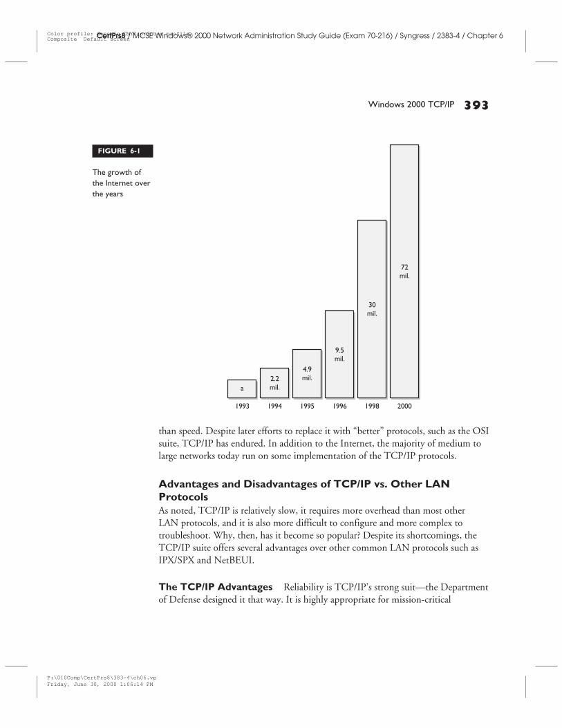
The ARPAnet grew, as nodes (computers attached to the network) were addedeach year. Eventually the military network split off, calling itself MILNET. Theremaining membership of the ARPAnet consisted primarily of an elite group ofacademics at major universities. However, in the late 1980s and early 1990s, theinternational network caught the eye of the business world. As commercialenterprises moved onto the network (which changed its name again during thisperiod), access became less expensive and widely available to companies andindividuals. The original ARPAnet thus evolved into today’s global Internet.According to most estimates, by 1999 there were over 50 million host computersconnected to the Internet. Figure 6-1 illustrates the growth of the Internet.
From its ARPAnet beginnings, the Internet has grown into a huge, world-widenetwork. The protocol suite upon which the ARPAnet was built was the TCP/IPsuite. The DoD designed it for that purpose, and the focus was reliability, rather
P:\010Comp\CertPrs8\383-4\ch06.vpFriday, June 30, 2000 1:06:14 PM
Color profile: Generic CMYK printer profileComposite Default screen
Windows 2000 TCP/IP 393
CertPrs8 / MCSE Windows® 2000 Network Administration Study Guide (Exam 70-216) / Syngress / 2383-4 / Chapter 6
than speed. Despite later efforts to replace it with “better” protocols, such as the OSIsuite, TCP/IP has endured. In addition to the Internet, the majority of medium tolarge networks today run on some implementation of the TCP/IP protocols.
Advantages and Disadvantages of TCP/IP vs. Other LANProtocolsAs noted, TCP/IP is relatively slow, it requires more overhead than most otherLAN protocols, and it is also more difficult to configure and more complex totroubleshoot. Why, then, has it become so popular? Despite its shortcomings, theTCP/IP suite offers several advantages over other common LAN protocols such asIPX/SPX and NetBEUI.
The TCP/IP Advantages Reliability is TCP/IP’s strong suit—the Departmentof Defense designed it that way. It is highly appropriate for mission-critical
FIGURE 6-1
The growth ofthe Internet overthe years
P:\010Comp\CertPrs8\383-4\ch06.vpFriday, June 30, 2000 1:06:14 PM
Color profile: Generic CMYK printer profileComposite Default screen
communications. But there are many other ways in which TCP/IP outdoes thecompetition and justifies the extra effort required to implement it:
■ Compatibility TCP/IP could almost be considered the universal protocol.It is supported by most operating systems and platforms, and allows highlydiverse systems—such as Macintosh workstations, UNIX servers, andWindows computers—to communicate with one another. Connectionto the Internet requires the TCP/IP protocols.
■ Scalability More than any other set of protocols in use, TCP/IP can scalefrom the smallest home network to the largest network of all: the Internet.Because of its unique addressing scheme, TCP/IP is especially suitable forlarge internetworks (networks that are interconnected with other networks).
■ Routability Closely related to scalability is the protocol stack’s capabilityof spanning subnets. Unlike unroutable protocols such as NetBEUI, its datapackets can cross from one network, or subnet, to another by travelingthrough devices called routers. Internet communication often involves ajourney through many different networks before the data reaches itsdestination.
Disadvantages of TCP/IP As already mentioned, compared to NetBEUI andNWLink (IPX/SPX), the TCP/IP protocols are slow. More resource overhead isrequired, and configuring the protocols correctly (IP address, subnet mask, defaultgateway) requires more knowledge and expertise. Most networking professionals feelthat these are small prices to pay for TCP/IP’s flexibility and power.
The TCP/IP Protocol SuiteTCP and IP make up the protocol “stack” that gets the messages to theirdestination, and ensures that they get there reliably. However, an entire suite ofprotocols has come to be associated with the name and included with most vendors’implementations.
Some of these are used to provide additional services, while others are usefulprimarily as information-gathering or troubleshooting tools. The different membersof the suite work at different “layers” of the networking process. In order tounderstand this, let’s take a look at the concept of layered networking models.
394 Chapter 6: Installing, Configuring, Managing, Monitoring, and Troubleshooting Network Protocols
CertPrs8 / MCSE Windows® 2000 Network Administration Study Guide (Exam 70-216) / Syngress / 2383-4 / Chapter 6
P:\010Comp\CertPrs8\383-4\ch06.vpFriday, June 30, 2000 1:06:15 PM
Color profile: Generic CMYK printer profileComposite Default screen
Windows 2000 TCP/IP 395
CertPrs8 / MCSE Windows® 2000 Network Administration Study Guide (Exam 70-216) / Syngress / 2383-4 / Chapter 6
TCP/IP and the DOD/OSI Networking ModelsIn the early days of computer networking, protocols were proprietary; that is, eachvendor of networking products developed its own set of rules. This meant thatcomputers using the same vendor’s products would be able to communicate witheach other, but not with computers that were using the networking product of adifferent vendor.
The solution to this problem was to develop protocols that are based on openstandards. Organizations such as the International Organization for Standardization(also called the ISO, which derives from the Greek word for “equal”) took on theresponsibility of overseeing the definition and control of these standards, andpublishing them so that they would be available to any vendor who wanted to createproducts that adhered to them. This is an advantage to consumers, because they areno longer forced to use the products of only one vendor. It can also benefit thevendors, in that its products are more widely compatible and can be used innetworks that started out using a different vendor’s products.
Graphical models were developed to represent these open standards. Modelsprovide an easy-to-understand description of the networking architecture and serveas the framework for the standards. The ISO’s OSI model has become a commonreference point for discussion of network protocols and connection devices. Anotherwidely used model is the DoD (Department of Defense) networking model, onwhich TCP/IP is based. Both of these are layered models that represent thecommunication process as a series of steps or levels. This layered approach providesa logical division of responsibility, where each layer handles prescribed functions.
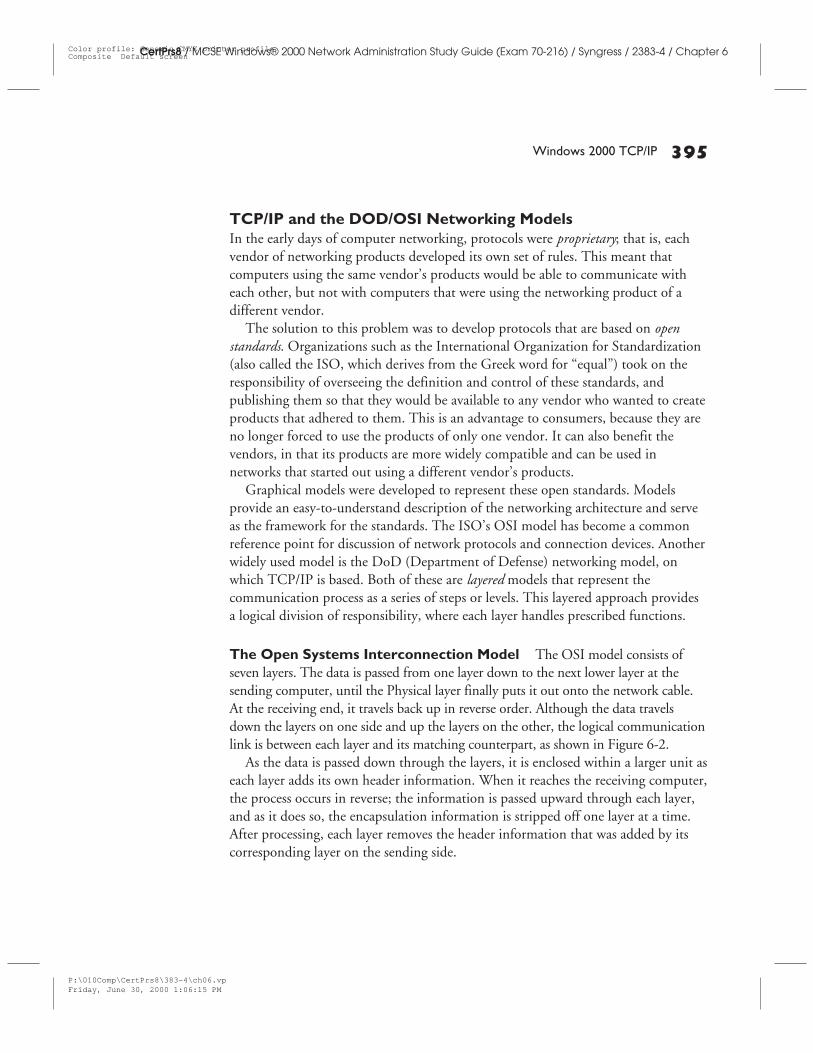
The Open Systems Interconnection Model The OSI model consists ofseven layers. The data is passed from one layer down to the next lower layer at thesending computer, until the Physical layer finally puts it out onto the network cable.At the receiving end, it travels back up in reverse order. Although the data travelsdown the layers on one side and up the layers on the other, the logical communicationlink is between each layer and its matching counterpart, as shown in Figure 6-2.
As the data is passed down through the layers, it is enclosed within a larger unit aseach layer adds its own header information. When it reaches the receiving computer,the process occurs in reverse; the information is passed upward through each layer,and as it does so, the encapsulation information is stripped off one layer at a time.After processing, each layer removes the header information that was added by itscorresponding layer on the sending side.
P:\010Comp\CertPrs8\383-4\ch06.vpFriday, June 30, 2000 1:06:15 PM
Color profile: Generic CMYK printer profileComposite Default screen
396 Chapter 6: Installing, Configuring, Managing, Monitoring, and Troubleshooting Network Protocols
CertPrs8 / MCSE Windows® 2000 Network Administration Study Guide (Exam 70-216) / Syngress / 2383-4 / Chapter 6
The process of enclosing data within a larger unit, with header informationadded by the protocol that is doing the enclosing, is called encapsulation.
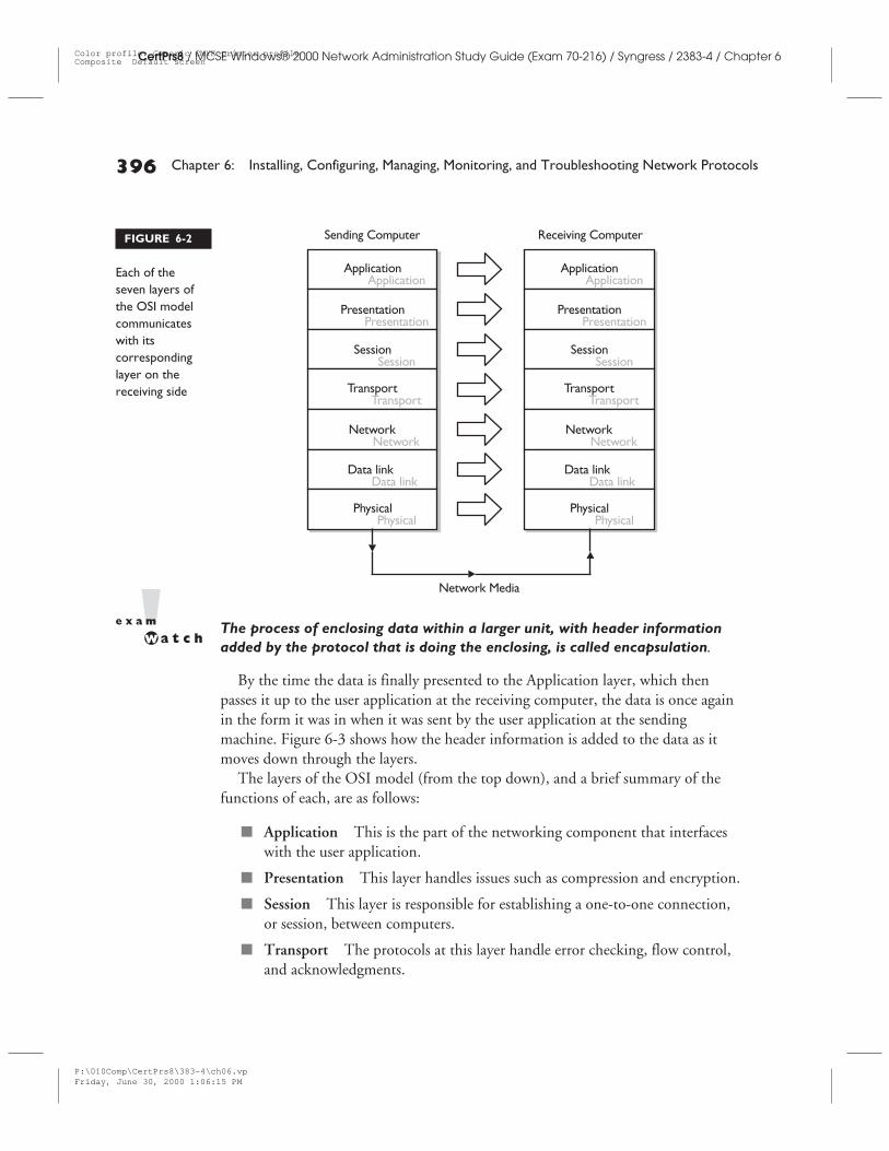
By the time the data is finally presented to the Application layer, which thenpasses it up to the user application at the receiving computer, the data is once againin the form it was in when it was sent by the user application at the sendingmachine. Figure 6-3 shows how the header information is added to the data as itmoves down through the layers.
The layers of the OSI model (from the top down), and a brief summary of thefunctions of each, are as follows:
■ Application This is the part of the networking component that interfaceswith the user application.
■ Presentation This layer handles issues such as compression and encryption.
■ Session This layer is responsible for establishing a one-to-one connection,or session, between computers.
■ Transport The protocols at this layer handle error checking, flow control,and acknowledgments.
FIGURE 6-2
Each of theseven layers ofthe OSI modelcommunicateswith itscorrespondinglayer on thereceiving side
P:\010Comp\CertPrs8\383-4\ch06.vpFriday, June 30, 2000 1:06:15 PM
Color profile: Generic CMYK printer profileComposite Default screen
Windows 2000 TCP/IP 397
CertPrs8 / MCSE Windows® 2000 Network Administration Study Guide (Exam 70-216) / Syngress / 2383-4 / Chapter 6
■ Network This layer is responsible for routing and logical addressing issues.
■ Data Link This layer deals with the physical addressing and linkestablishment.
■ Physical This layer interfaces with the hardware, and does not add headersto the data.
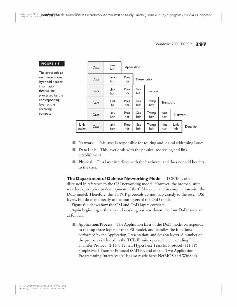
The Department of Defense Networking Model TCP/IP is oftendiscussed in reference to the OSI networking model. However, the protocol suitewas developed prior to development of the OSI model, and in conjunction with theDoD model. Therefore, the TCP/IP protocols do not map exactly to the seven OSIlayers, but do map directly to the four layers of the DoD model.
Figure 6-4 shows how the OSI and DoD layers correlate.Again beginning at the top and working our way down, the four DoD layers are
as follows:
■ Application/Process The Application layer of the DoD model correspondsto the top three layers of the OSI model, and handles the functionsperformed by the Application, Presentation, and Session layers. A number ofthe protocols included in the TCP/IP suite operate here, including FileTransfer Protocol (FTP), Telnet, HyperText Transfer Protocol (HTTP),Simple Mail Transfer Protocol (SMTP), and others. Two ApplicationProgramming Interfaces (APIs) also reside here: NetBIOS and WinSock
FIGURE 6-3
The protocols ateach networkinglayer add headerinformationthat will beprocessed by thecorrespondinglayer at thereceivingcomputer
P:\010Comp\CertPrs8\383-4\ch06.vpFriday, June 30, 2000 1:06:16 PM
Color profile: Generic CMYK printer profileComposite Default screen
398 Chapter 6: Installing, Configuring, Managing, Monitoring, and Troubleshooting Network Protocols
CertPrs8 / MCSE Windows® 2000 Network Administration Study Guide (Exam 70-216) / Syngress / 2383-4 / Chapter 6
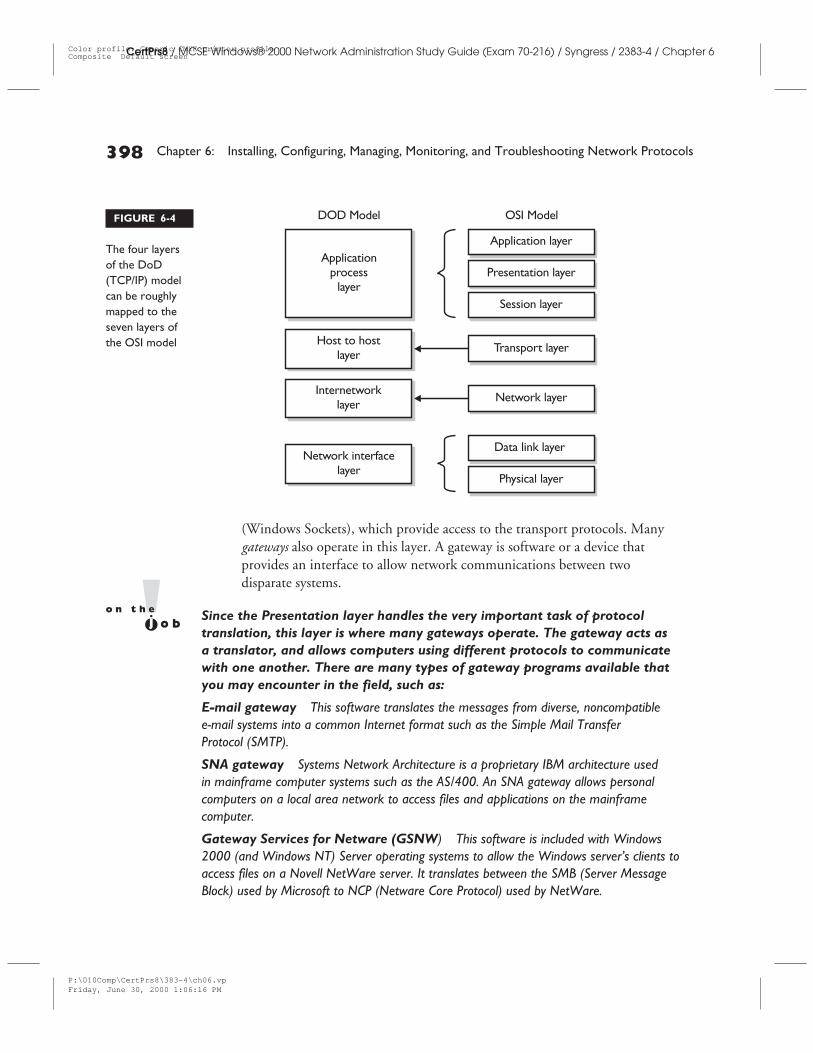
(Windows Sockets), which provide access to the transport protocols. Manygateways also operate in this layer. A gateway is software or a device thatprovides an interface to allow network communications between twodisparate systems.
Since the Presentation layer handles the very important task of protocoltranslation, this layer is where many gateways operate. The gateway acts asa translator, and allows computers using different protocols to communicatewith one another. There are many types of gateway programs available thatyou may encounter in the field, such as:
E-mail gateway This software translates the messages from diverse, noncompatiblee-mail systems into a common Internet format such as the Simple Mail TransferProtocol (SMTP).
SNA gateway Systems Network Architecture is a proprietary IBM architecture usedin mainframe computer systems such as the AS/400. An SNA gateway allows personalcomputers on a local area network to access files and applications on the mainframecomputer.
Gateway Services for Netware (GSNW) This software is included with Windows2000 (and Windows NT) Server operating systems to allow the Windows server’s clients toaccess files on a Novell NetWare server. It translates between the SMB (Server MessageBlock) used by Microsoft to NCP (Netware Core Protocol) used by NetWare.
FIGURE 6-4
The four layersof the DoD(TCP/IP) modelcan be roughlymapped to theseven layers ofthe OSI model
P:\010Comp\CertPrs8\383-4\ch06.vpFriday, June 30, 2000 1:06:16 PM
Color profile: Generic CMYK printer profileComposite Default screen
CertPrs8 / MCSE Windows® 2000 Network Administration Study Guide (Exam 70-216) / Syngress / 2383-4 / Chapter 6
■ Host to Host (Transport) This layer is basically the same as the Transportlayer in the OSI model. It is responsible for flow control, acknowledgments,sequencing (ordering) of packets, and establishment of end-to-endcommunications. TCP and the User Datagram Protocol (UDP) operateat this level.
■ Internetwork This layer matches the Network layer in the OSI model.The Internet Protocol (IP) works here to route and deliver packets to thecorrect destination address. Other protocols that operate at this layer includethe Address Resolution Protocol (ARP), Reverse Address Resolution Protocol(RARP), and the Internet Control Message Protocol (ICMP).
■ Network Interface This bottom layer of the DoD model corresponds toboth the Data Link and Physical layers of OSI. It provides the interfacebetween the network architecture (Ethernet, Token Ring, AppleTalk, etc.)and the upper layers, as well as the physical (hardware) issues.
The most critical members of the TCP/IP suite are the Network and Transportlayer protocols (or Internetwork and Host-to-Host): TCP/UDP and IP.
The Internetwork Layer ProtocolsThe protocols that operate at the Internet layer of the DoD model (Network layerof the OSI model) handle logical (IP) addressing issues and routing.
Routers work at the Internetwork layer. A router can be a dedicated device,or you can configure a Windows NT or Windows 2000 computer to routeIP packets by installing multiple network interface cards and enabling IPforwarding. Routers are necessary for communication to take place betweencomputers that are not on the same network (subnet).
IP routing involves discovering a pathway from the sending computer (orforwarding router) to the destination computer whose address is designated inthe IP header.
The protocol most commonly associated with this layer is IP, the InternetProtocol (IPX, as part of the IPX/SPX stack, also operates at this layer, andWindows 2000 also supports IPX routing).
IP IP is a connectionless protocol; this means it must depend on TCP at theTransport layer above it to provide a connection if necessary.
Windows 2000 TCP/IP 399
CertPrs8 / MCSE Windows® 2000 Network Administration Study Guide (Exam 70-216) / Syngress / 2383-4 / Chapter 6
P:\010Comp\CertPrs8\383-4\ch06.vpFriday, June 30, 2000 1:06:16 PM
Color profile: Generic CMYK printer profileComposite Default screen
400 Chapter 6: Installing, Configuring, Managing, Monitoring, and Troubleshooting Network Protocols
CertPrs8 / MCSE Windows® 2000 Network Administration Study Guide (Exam 70-216) / Syngress / 2383-4 / Chapter 6
A connection-oriented protocol is one that establishes a direct connectionbefore sending data. A connection-oriented protocol works something like aphone call: If you wish to have a conversion with Mr. Smith, you would dialhis number, ask for him, and verify that he is the party to whom you’respeaking before plunging into the discussion. Connectionless protocols workmore like sending a postcard: You write your message, address it to Mr. Smith,and drop it in the mailbox, hoping it will reach its destination. Mr. Smith wasnot aware that the message was coming until it arrived, and you have no wayof knowing whether or not Mr. Smith received your communication.
Although IP does not establish a connection or acknowledgment receipt ofmessages, it is able to use number sequencing to break down and reassemblemessages, and uses a checksum to perform error checking on the IP header.
ICMP and IGMP The Internet Control Message Protocol (ICMP) is a TCP/IPstandard that allows hosts and routers that use IP communication to report errorsand exchange limited control and status information. The PING utility (discussedlater in this chapter) works by sending an ICMP echo request message and recordingthe response of echo replies.
The Internet Group Management Protocol is used for multicasting, which is amethod of sending a message to multiple hosts but only addressing it to a singleaddress. Members of a multicast group can be defined, and then when a message issent to the group address, only those computers that belong to the group will receiveit. IGMP is used to exchange membership status information between IP routersthat support multicasting and members of multicast groups.
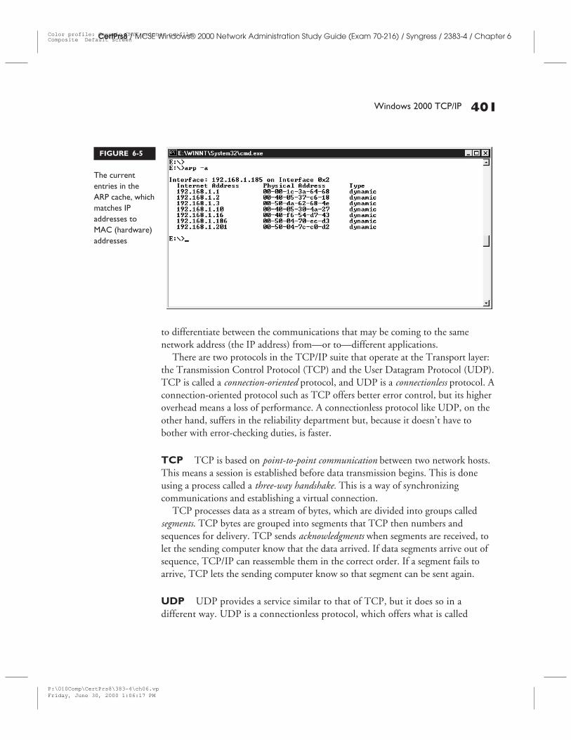
ARP and RARP The Address Resolution Protocol (ARP) is used to resolve IP(logical) addresses to Media Access Control (MAC) physical hardware addresses.ARP uses broadcasts to discover the hardware addresses, and stores the informationin its arp cache.
RARP is the Reverse Address Resolution Protocol, which does the same thing inreverse; that is, it takes a physical address and resolves it to an IP address. The arp –acommand can be used to view the current entries in the ARP cache. See Figure 6-5for an illustration of this IP address to MAC address list.
The Transport Layer ProtocolsRemember that the Transport layer’s primary responsibility is reliability; it mustverify that the data arrives complete and in good condition,. It also must have a way
P:\010Comp\CertPrs8\383-4\ch06.vpFriday, June 30, 2000 1:06:16 PM
Color profile: Generic CMYK printer profileComposite Default screen
Windows 2000 TCP/IP 401
CertPrs8 / MCSE Windows® 2000 Network Administration Study Guide (Exam 70-216) / Syngress / 2383-4 / Chapter 6
to differentiate between the communications that may be coming to the samenetwork address (the IP address) from—or to—different applications.
There are two protocols in the TCP/IP suite that operate at the Transport layer:the Transmission Control Protocol (TCP) and the User Datagram Protocol (UDP).TCP is called a connection-oriented protocol, and UDP is a connectionless protocol. Aconnection-oriented protocol such as TCP offers better error control, but its higheroverhead means a loss of performance. A connectionless protocol like UDP, on theother hand, suffers in the reliability department but, because it doesn’t have tobother with error-checking duties, is faster.
TCP TCP is based on point-to-point communication between two network hosts.This means a session is established before data transmission begins. This is doneusing a process called a three-way handshake. This is a way of synchronizingcommunications and establishing a virtual connection.
TCP processes data as a stream of bytes, which are divided into groups calledsegments. TCP bytes are grouped into segments that TCP then numbers andsequences for delivery. TCP sends acknowledgments when segments are received, tolet the sending computer know that the data arrived. If data segments arrive out ofsequence, TCP/IP can reassemble them in the correct order. If a segment fails toarrive, TCP lets the sending computer know so that segment can be sent again.
UDP UDP provides a service similar to that of TCP, but it does so in adifferent way. UDP is a connectionless protocol, which offers what is called
FIGURE 6-5
The currententries in theARP cache, whichmatches IPaddresses toMAC (hardware)addresses
P:\010Comp\CertPrs8\383-4\ch06.vpFriday, June 30, 2000 1:06:17 PM
Color profile: Generic CMYK printer profileComposite Default screen
402 Chapter 6: Installing, Configuring, Managing, Monitoring, and Troubleshooting Network Protocols
CertPrs8 / MCSE Windows® 2000 Network Administration Study Guide (Exam 70-216) / Syngress / 2383-4 / Chapter 6
best-effort delivery. This means that UDP does not guarantee delivery, nor does itverify sequencing. If a sending host needs reliable communication, it should useeither TCP or a program that provides its own sequencing and acknowledgmentservices at the Application level.
Applications that need to send only a small amount of data at a time, or thosethat place a priority on speed of transmission rather than reliability, use UDP.
Ports and Sockets Thanks to the multitasking capabilities of Windows 2000and other modern operating systems, you can use more than one networkapplication simultaneously. For example, you can use your Web browser to accessyour company’s homepage at the same time your e-mail software is downloadingyour e-mail. You probably know that TCP/IP uses an IP address to identify yourcomputer on the network, and get the messages to the correct system, but how doesit separate the response to your browser’s request from your incoming mail whenboth arrive at the same IP address?
That’s where ports come in. Remember we said that the two parts of an IPaddress that represent the network identification and the host (individualcomputer) identification are somewhat like a street name and an individual streetnumber. In this analogy, the port number designates the specific apartment orsuite within the building.
TCP and UDP, the Transport layer protocols, both use port numbers to ensurethat the data intended for Apartment A doesn’t get sent to Apartment B instead.
A socket is the combination of an IP address and a port number.
TCP Sliding Windows TCP is a reliable protocol, and as a result, in a TCPcommunication, every segment sent must be acknowledged. That way, if onesegment doesn’t arrive at its destination (and thus the receiving computer does notsend back an acknowledgment for it), it will be sent again.
TCP has to have a way to control the “flow” of data transmission when multipleTCP connections have to share a busy link. Flow control is necessary so that thereceiving computer doesn’t get “overwhelmed” by a sending computer that delugesit with data faster than it can be processed, or alternately so that the receiver doesn’tsit around waiting for the data to “trickle” in.
Flow control is the process of matching the outflow of data from the sendingcomputer to the receiving computer’s inflow. This is done by setting a limit on thenumber of packets that can be sent before acknowledgment is required, whichsignals the sender to slow down (or stop and wait) if data is “piling up” in the
P:\010Comp\CertPrs8\383-4\ch06.vpFriday, June 30, 2000 1:06:17 PM
Color profile: Generic CMYK printer profileComposite Default screen
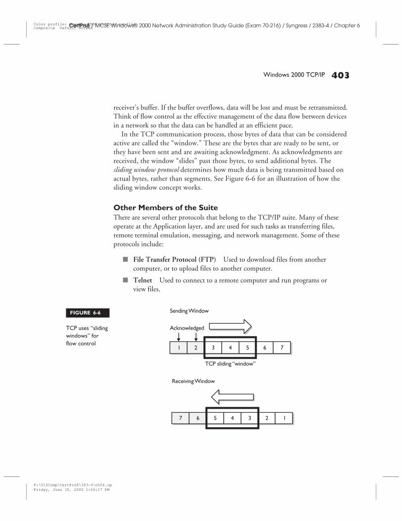
receiver’s buffer. If the buffer overflows, data will be lost and must be retransmitted.Think of flow control as the effective management of the data flow between devicesin a network so that the data can be handled at an efficient pace.
In the TCP communication process, those bytes of data that can be consideredactive are called the “window.” These are the bytes that are ready to be sent, orthey have been sent and are awaiting acknowledgment. As acknowledgments arereceived, the window “slides” past those bytes, to send additional bytes. Thesliding window protocol determines how much data is being transmitted based onactual bytes, rather than segments. See Figure 6-6 for an illustration of how thesliding window concept works.
Other Members of the SuiteThere are several other protocols that belong to the TCP/IP suite. Many of theseoperate at the Application layer, and are used for such tasks as transferring files,remote terminal emulation, messaging, and network management. Some of theseprotocols include:
■ File Transfer Protocol (FTP) Used to download files from anothercomputer, or to upload files to another computer.
■ Telnet Used to connect to a remote computer and run programs orview files.
Windows 2000 TCP/IP 403
CertPrs8 / MCSE Windows® 2000 Network Administration Study Guide (Exam 70-216) / Syngress / 2383-4 / Chapter 6
FIGURE 6-6
TCP uses “slidingwindows” forflow control
P:\010Comp\CertPrs8\383-4\ch06.vpFriday, June 30, 2000 1:06:17 PM
Color profile: Generic CMYK printer profileComposite Default screen
■ Simple Mail Transfer Protocol Used for sending Internet mail (usuallyused in conjunction with the Post Office Protocol (POP), which is used toretrieve incoming mail from the mail server.
■ Simple Network Management Protocol (SNMP) Used to monitor andmanage TCP/IP networks. SNMP has two components, the SNMP Agentand the SNMP Management System, which use SNMP messages sent usingUDP to communicate host information, which is stored in a ManagementInformation Base (MIB).
The Application Programming Interfaces, APIs, are called boundary layersin Microsoft’s own Windows networking model. The two supported APIsin Windows 2000 networking are NetBIOS and WinSock. NetBIOScommunications use a destination name (called a NetBIOS name) and amessage location to get the data to the correct destination. NetBIOS supports asession mode, for establishing a connection and transfer of large messages, anda datagram mode, for connectionless transmissions such as broadcast messages.A WinSock program handles input/output requests for Internet applications in aWindows operating system, using the sockets convention for connecting with andexchanging data between two processes. WinSock runs as a .dll file (dynamic linklibrary). A .dll file is a collection of small programs, any of which can be loadedwhen an application needs to use it, but it isn’t required to be included as partof the application.
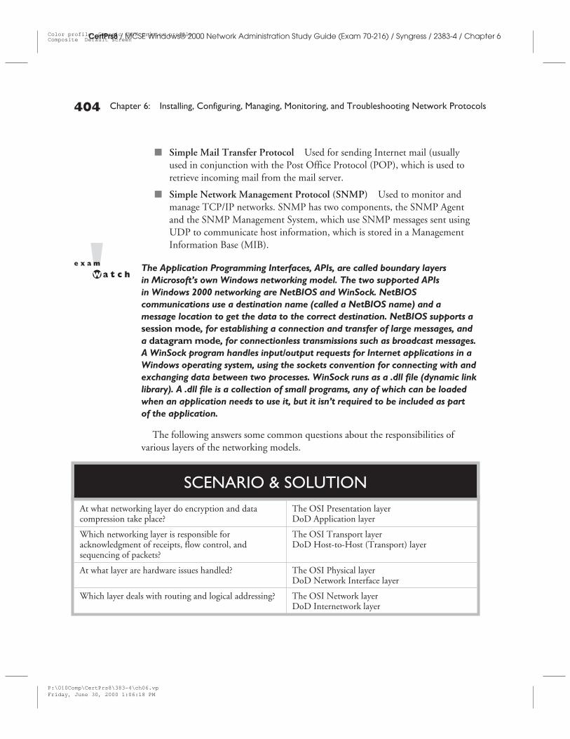
The following answers some common questions about the responsibilities ofvarious layers of the networking models.
CertPrs8 / MCSE Windows® 2000 Network Administration Study Guide (Exam 70-216) / Syngress / 2383-4 / Chapter 6
404 Chapter 6: Installing, Configuring, Managing, Monitoring, and Troubleshooting Network Protocols
At what networking layer do encryption and datacompression take place?
The OSI Presentation layerDoD Application layer
Which networking layer is responsible foracknowledgment of receipts, flow control, andsequencing of packets?
The OSI Transport layerDoD Host-to-Host (Transport) layer
At what layer are hardware issues handled? The OSI Physical layerDoD Network Interface layer
Which layer deals with routing and logical addressing? The OSI Network layerDoD Internetwork layer
SCENARIO & SOLUTION
P:\010Comp\CertPrs8\383-4\ch06.vpFriday, June 30, 2000 1:06:18 PM
Color profile: Generic CMYK printer profileComposite Default screen
Windows 2000 TCP/IP 405
CertPrs8 / MCSE Windows® 2000 Network Administration Study Guide (Exam 70-216) / Syngress / 2383-4 / Chapter 6
EX
ER
CIS
E6-
1
CertCam 6-1
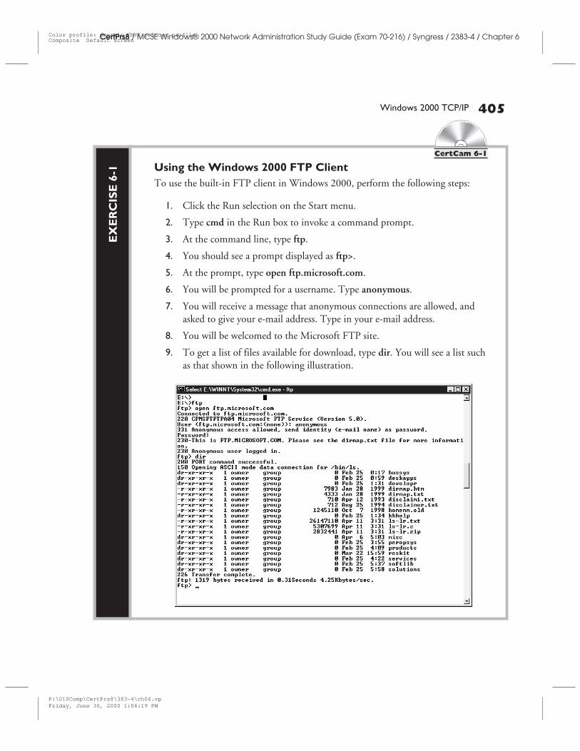
Using the Windows 2000 FTP ClientTo use the built-in FTP client in Windows 2000, perform the following steps:
1. Click the Run selection on the Start menu.
2. Type cmd in the Run box to invoke a command prompt.
3. At the command line, type ftp.
4. You should see a prompt displayed as ftp>.
5. At the prompt, type open ftp.microsoft.com.
6. You will be prompted for a username. Type anonymous.
7. You will receive a message that anonymous connections are allowed, andasked to give your e-mail address. Type in your e-mail address.
8. You will be welcomed to the Microsoft FTP site.
9. To get a list of files available for download, type dir. You will see a list suchas that shown in the following illustration.
P:\010Comp\CertPrs8\383-4\ch06.vpFriday, June 30, 2000 1:06:19 PM
Color profile: Generic CMYK printer profileComposite Default screen
406 Chapter 6: Installing, Configuring, Managing, Monitoring, and Troubleshooting Network Protocols
CertPrs8 / MCSE Windows® 2000 Network Administration Study Guide (Exam 70-216) / Syngress / 2383-4 / Chapter 6
You can use the GET command to specify a file to be downloaded, or the PUTcommand to specify a file to be uploaded. For a complete listing of FTP commands,type help at the ftp prompt.
CERTIFICATION OBJECTIVE 6.02
IP AddressingThe IP address is a logical address, assigned by the network administrator. It bearsno direct relation to the network interface card’s physical address (called the MACaddress because it is used at the Media Access Control sublayer of the OSI’s DataLink layer). The MAC address is hard-coded into a chip on the network cardin 1the typical Ethernet network. The Address Resolution Protocol (ARP), whichwas discussed earlier in this chapter, has the task of translating IP addresses toMAC addresses.
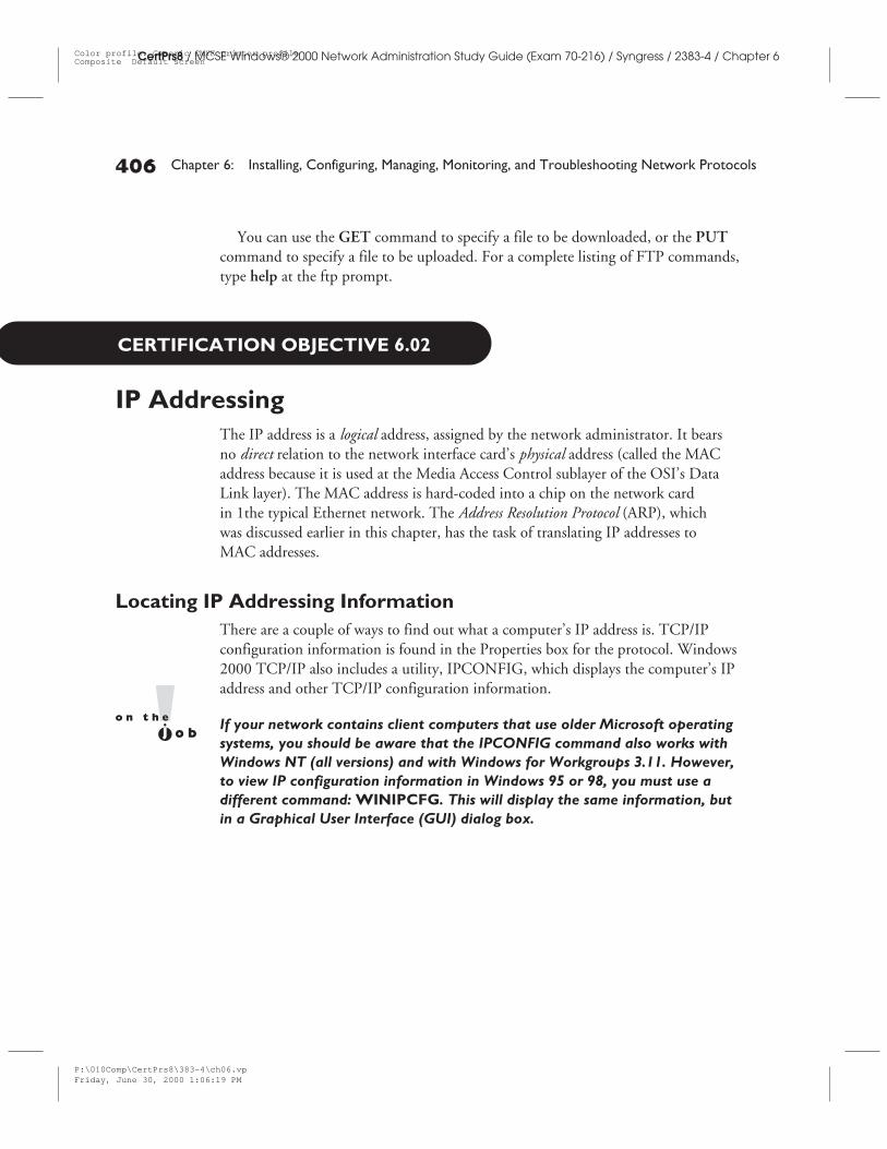
Locating IP Addressing InformationThere are a couple of ways to find out what a computer’s IP address is. TCP/IPconfiguration information is found in the Properties box for the protocol. Windows2000 TCP/IP also includes a utility, IPCONFIG, which displays the computer’s IPaddress and other TCP/IP configuration information.
If your network contains client computers that use older Microsoft operatingsystems, you should be aware that the IPCONFIG command also works withWindows NT (all versions) and with Windows for Workgroups 3.11. However,to view IP configuration information in Windows 95 or 98, you must use adifferent command: WINIPCFG. This will display the same information, butin a Graphical User Interface (GUI) dialog box.
P:\010Comp\CertPrs8\383-4\ch06.vpFriday, June 30, 2000 1:06:19 PM
Color profile: Generic CMYK printer profileComposite Default screen
IP Addressing 407
CertPrs8 / MCSE Windows® 2000 Network Administration Study Guide (Exam 70-216) / Syngress / 2383-4 / Chapter 6
EX
ER
CIS
E6-
2
CertCam 6-2
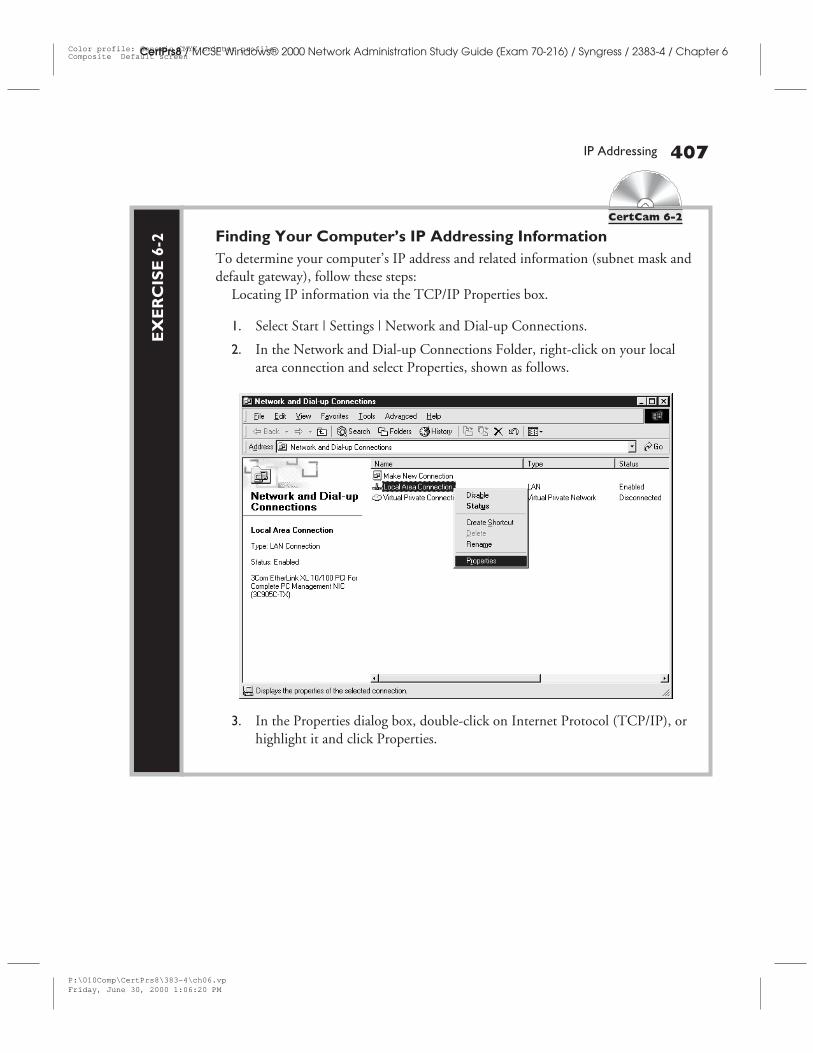
Finding Your Computer’s IP Addressing InformationTo determine your computer’s IP address and related information (subnet mask anddefault gateway), follow these steps:
Locating IP information via the TCP/IP Properties box.
1. Select Start | Settings | Network and Dial-up Connections.
2. In the Network and Dial-up Connections Folder, right-click on your localarea connection and select Properties, shown as follows.
3. In the Properties dialog box, double-click on Internet Protocol (TCP/IP), orhighlight it and click Properties.
P:\010Comp\CertPrs8\383-4\ch06.vpFriday, June 30, 2000 1:06:20 PM
Color profile: Generic CMYK printer profileComposite Default screen
408 Chapter 6: Installing, Configuring, Managing, Monitoring, and Troubleshooting Network Protocols
CertPrs8 / MCSE Windows® 2000 Network Administration Study Guide (Exam 70-216) / Syngress / 2383-4 / Chapter 6
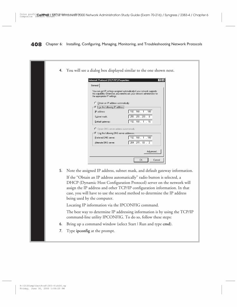
4. You will see a dialog box displayed similar to the one shown next.
5. Note the assigned IP address, subnet mask, and default gateway information.
If the “Obtain an IP address automatically” radio button is selected, aDHCP (Dynamic Host Configuration Protocol) server on the network willassign the IP address and other TCP/IP configuration information. In thatcase, you will have to use the second method to determine the IP addressbeing used by the computer.
Locating IP information via the IPCONFIG command.
The best way to determine IP addressing information is by using the TCP/IPcommand-line utility IPCONFIG. To do so, follow these steps:
6. Bring up a command window (select Start | Run and type cmd).
7. Type ipconfig at the prompt.
P:\010Comp\CertPrs8\383-4\ch06.vpFriday, June 30, 2000 1:06:20 PM
Color profile: Generic CMYK printer profileComposite Default screen
IP Addressing 409
CertPrs8 / MCSE Windows® 2000 Network Administration Study Guide (Exam 70-216) / Syngress / 2383-4 / Chapter 6
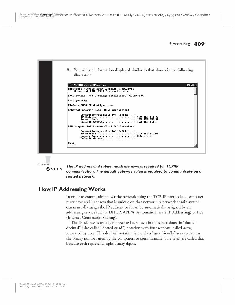
The IP address and subnet mask are always required for TCP/IPcommunication. The default gateway value is required to communicate on arouted network.
How IP Addressing WorksIn order to communicate over the network using the TCP/IP protocols, a computermust have an IP address that is unique on that network. A network administratorcan manually assign the IP address, or it can be automatically assigned by anaddressing service such as DHCP, APIPA (Automatic Private IP Addressing),or ICS(Internet Connection Sharing).
The IP address is usually represented as shown in the screenshots, in “dotteddecimal” (also called “dotted quad”) notation with four sections, called octets,separated by dots. This decimal notation is merely a “user friendly” way to expressthe binary number used by the computers to communicate. The octets are called thatbecause each represents eight binary digits.
8. You will see information displayed similar to that shown in the followingillustration.
P:\010Comp\CertPrs8\383-4\ch06.vpFriday, June 30, 2000 1:06:21 PM
Color profile: Generic CMYK printer profileComposite Default screen
410 Chapter 6: Installing, Configuring, Managing, Monitoring, and Troubleshooting Network Protocols
CertPrs8 / MCSE Windows® 2000 Network Administration Study Guide (Exam 70-216) / Syngress / 2383-4 / Chapter 6
To identify which octet we’re talking about, they are often referred to as the “W,”“X,” “Y,” and “Z” as follows:
w.x.y.z
Ones and Zeros: Binary AddressingLet’s take a look at how IP addresses look in binary. This will help you tounderstand what the numbers really represent and how the computer uses them forcommunication.
For example: The IP address 192.168.1.185 really represents the following binarynumber: 11000000.10101000.00000001.10111001.
This number is made up of four groups of eight binary digits, the octetsmentioned earlier. Binary uses only two digits—0 and 1—to represent all numerical
The IP address
IP addressing, used by the network protocolsto deliver packets to the proper destination, isanalogous to street addressing used by the postalservice to deliver mail to the proper home oroffice. If you wish to send a letter to a specificlocation, you must indicate the street addresson the envelope. Similarly, the computer’sIP address is placed on the data packet’s“envelope,” in the form of header information.You also place a return address on the envelopeso the post office will know where it originated
in case it can’t be delivered. The sendingcomputer’s address, called the source address,is likewise included in the header (there maybe other information in addition to the sourceand destination address in some headers, justas you might have additional information orinstructions, such as “Do not forward” or“Fragile—Do not bend” on the envelopeyou send through the postal system).
—Debra Littlejohn Shinder, MCSE, MCP+I, MCT
FROM THE CLASSROOM
P:\010Comp\CertPrs8\383-4\ch06.vpFriday, June 30, 2000 1:06:21 PM
Color profile: Generic CMYK printer profileComposite Default screen
IP Addressing 411
CertPrs8 / MCSE Windows® 2000 Network Administration Study Guide (Exam 70-216) / Syngress / 2383-4 / Chapter 6
values. Binary is a base two system, as opposed to decimal, which is a base ten systembecause it uses ten digits—0 through 9—to represent all numerical values.
How do you convert decimal to its binary equivalent? Well, you could just use theWindows calculator in scientific mode (choose “Scientific” from the View menu).Check the dec radio button and enter the number in decimal, then click on the binradio button and Tada! As if by magic, you have the binary equivalent.
But you also need to know how to perform the calculation without the assistanceof a calculator. It’s really not as difficult as you may think.
Converting Decimal to BinaryLet’s take a look at an octet:
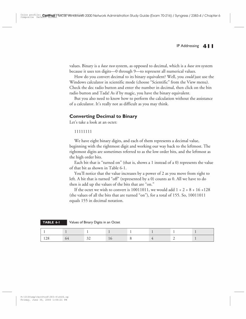
11111111
We have eight binary digits, and each of them represents a decimal value,beginning with the rightmost digit and working our way back to the leftmost. Therightmost digits are sometimes referred to as the low order bits, and the leftmost asthe high order bits.
Each bit that is “turned on” (that is, shows a 1 instead of a 0) represents the valueof that bit as shown in Table 6-1.
You’ll notice that the value increases by a power of 2 as you move from right toleft. A bit that is turned “off” (represented by a 0) counts as 0. All we have to dothen is add up the values of the bits that are “on.”
If the octet we wish to convert is 10011011, we would add 1 + 2 + 8 + 16 +128(the values of all the bits that are turned “on”), for a total of 155. So, 10011011equals 155 in decimal notation.
1 1 1 1 1 1 1 1
128 64 32 16 8 4 2 1
TABLE 6-1 Values of Binary Digits in an Octet
P:\010Comp\CertPrs8\383-4\ch06.vpFriday, June 30, 2000 1:06:21 PM
Color profile: Generic CMYK printer profileComposite Default screen
412 Chapter 6: Installing, Configuring, Managing, Monitoring, and Troubleshooting Network Protocols
CertPrs8 / MCSE Windows® 2000 Network Administration Study Guide (Exam 70-216) / Syngress / 2383-4 / Chapter 6
The Components of an IP AddressWhat does this mean, then, in terms of the IP addresses we work with every day?Generally, when we configure TCP/IP properties, we enter IP addresses in dotteddecimal notation. An IP address in its “pure” binary form consists of four octets (eachoctet being made up of eight binary digits), or 32 bits. The dotted decimal formshows the octets converted to their decimal equivalent with each octet separated bya dot. Thus, the address that the computer sees as 10011110 11101000 0001100111111001 will be expressed as 158.232.25.249 (do the calculations as shown earlieror use the scientific calculator to make the conversion).
Network and Host ID This address is really made up of two parts, just as yourstreet address contains both the house number and the street name; for example, 123Main Street. Many houses share the “street name” portion of the address (everyoneelse on your street). There may also be other houses in your neighborhood that havethe house number “123,” but they will be on different streets. It’s the combinationof the house number and street name that makes up the unique identifier thatdescribes to others which house is yours.
IP addresses work in a similar fashion. Part of the address is the network ID,which identifies the network (or subnet) on which the computer is located. Allcomputers on the subnet share this part of the address. The second part of an IPaddress is called the host ID, and identifies the individual computer on that networkor subnet. Combined, they create a unique address that differentiates this computerfrom all others on the internetwork.
The Role of the Subnet Mask How do we know which of the octets, or partsof the IP address, indicate the network ID, and which ones indicate the host ID? Itwould be easier if, for instance, the first octet always indicated the network, and thelast three always indicated the host. Unfortunately, it’s not that simple. However, wecan determine what part of the IP address pertains to which by taking a look at oursubnet mask.
The subnet mask is another 32-bit binary number, expressed in the same formas an IP address, but its purpose is to tell us (and more importantly, to tell thecomputers) which part of the IP address is masked (and thus represents the networkID). In the binary form of the subnet mask, the masked bits are those that are “on,”or set to 1.
If the first eight bits from the left in the subnet mask (the first octet) are all ones,and the rest of the bits are zeros, that means the first octet represents the network ID
P:\010Comp\CertPrs8\383-4\ch06.vpFriday, June 30, 2000 1:06:21 PM
Color profile: Generic CMYK printer profileComposite Default screen
CertPrs8 / MCSE Windows® 2000 Network Administration Study Guide (Exam 70-216) / Syngress / 2383-4 / Chapter 6
and the remaining three octets represent the host ID. Let’s convert that to decimal,since we usually see the subnet mask expressed in dotted decimal in the TCP/IPconfiguration.
11111111.00000000.00000000.00000000 =255.0.0.0.
This generally means the first portion of the IP address identifies the network onwhich the computer “lives,” and the last three parts identify the specific computer(host) on that network. In other words, if our IP address is 103.24.125.6 with asubnet mask of 255.0.0.0, the first octet (103) identifies the network, and theremaining three (24.125.6) identify the host computer on that network.
Certain addresses are used for special purposes. A host number of all 0s isused to identify the network, and a host number of all 255s is used as thebroadcast address, to send messages to all computers on that network.
There is one more thing we must factor in: the address class to which the IPaddress belongs.
Address ClassesIn order for computers to communicate on a worldwide global internetwork like theInternet, which requires that each computer have a unique IP address, there must besome centralized authority in charge of assigning addresses and ensuring that noneare duplicated. This has been handled by the Internet Assigned Numbers Authority(IANA) and the InterNIC, a company tasked with that responsibility. Traditionally,blocks of IP addresses have been assigned in “lumps” to organizations and InternetService Providers (ISPs), depending on how many host addresses were needed fortheir networks.
These blocks of addresses came in three basic sizes: large, medium, and small. Thenetworks for which these blocks of addresses were assigned were called Class A, B,and C networks.
Class A AddressesClass A addresses are for the “large size” networks, those that have a tremendousnumber of computers, and thus a need for many host addresses. Class A addressesalways begin with a 0 in the first octet (also called the W octet). This will be the first
IP Addressing 413
P:\010Comp\CertPrs8\383-4\ch06.vpFriday, June 30, 2000 1:06:21 PM
Color profile: Generic CMYK printer profileComposite Default screen
414 Chapter 6: Installing, Configuring, Managing, Monitoring, and Troubleshooting Network Protocols
CertPrs8 / MCSE Windows® 2000 Network Administration Study Guide (Exam 70-216) / Syngress / 2383-4 / Chapter 6
bit on the left. This leaves seven bits for the individual network ID, and 24 bits toidentify the host computers. When we convert to decimal, we see that this means aClass A address will have a decimal value in the first octet of 127 or less.
Class A networks can be assigned addresses with a first octet of 1–126. The127.0.0.0 network, although technically a Class A, is reserved for use as the“loopback Network ID.” This is a test Network ID used to troubleshootTCP/IP connectivity. The address 127.0.0.1 is generally known as the“loopback” address, but a message sent to any valid IP address with theloopback network will “loop back” to the sender (regardless of the sender’sIP address). Unfortunately, this means the more than 24 million additionaladdresses in the 127.0.0.0 network cannot be assigned and are wasted.
Class A addresses, because they use only the first octet to identify the network, arelimited in number. However, each Class A network can have a huge number of hostcomputers, over 16 million. The Class A network numbers were all used up sometime ago; they have been assigned to very large organizations such as IBM, MIT,and General Electric.
Class B AddressesClass B networks are the “medium size” networks. Class B networks use the first twooctets (the 16 leftmost bits) to identify the network, and the last two octets (or the16 rightmost bits) to identify the host computers. This means there can be far moreClass B networks than Class As (over 16,000), but each can have fewer hosts (“only”65,535 each). Class B addresses always begin with a 10 for the two leftmost bits inthe W octet, and the network is defined by the first two octets, which translates todecimal values of 128 through 191 for the first octet. 16 bits identify the NetworkID, and the remaining 16 bits identify the Host ID. Microsoft’s network is anexample of a Class B network.
Class C AddressesThe smallest sized block of addresses designated by a class is the Class C network,each of which can have only 254 hosts. However, there can be over 2 million ClassC networks. A Class C network always has 110 as its first three bits. This leaves 24
P:\010Comp\CertPrs8\383-4\ch06.vpFriday, June 30, 2000 1:06:22 PM
Color profile: Generic CMYK printer profileComposite Default screen
IP Addressing 415
CertPrs8 / MCSE Windows® 2000 Network Administration Study Guide (Exam 70-216) / Syngress / 2383-4 / Chapter 6
bits to identify the network, with only 8 bits to use for host IDs. A Class C network,in decimal notation, will have a first octet decimal value of 192 through 223.
Don’t be confused if you read in some texts that the network ID in a Class Bnetwork is identified by 14 bits rather than 16, or in a Class C by 21 insteadof 24. Technically this is correct—the first 2 bits define the address class, andthe next 14 define the individual network. To simplify our understanding ofaddressing, these two are usually referred to together as the “network ID.”
There are many, many class C networks. Most Internet Service Providers (ISPs)have been assigned Class C network numbers.
The address ranges 10.x.x.x, 172.16.x.x, and 192.168.x.x are reserved for useas private addresses. That is, these address ranges cannot be assigned by theInternet authorities to any network connected to the public Internet, but canbe used as internal addresses that are not connected to the public network,without being required to be registered. Private addresses cannot send toor receive traffic from the Internet—at least, not directly. If a LAN is usingprivate addresses, and the computers on the LAN need to communicatewith Internet locations, the private addresses must be translated to a publicaddress. NAT (Network Address Translation) software is used for this purpose,and Windows 2000 includes built-in NAT support.
Class D and E AddressesWe said there are three network sizes, so where do the Class D and E addressesfit in? These two classes are not assigned to networks, but are reserved and usedfor special purposes.
Class D addresses, whose four high order (leftmost) bits in the W octet are1110, are used for multicasting. This is a method of sending a message to multiplecomputers simultaneously.
Class E addresses, with four high order bits of 1111, are reserved to be usedfor experimental and testing purposes.
The following provides a quick reference for defining the ranges of IPaddress classes.
P:\010Comp\CertPrs8\383-4\ch06.vpFriday, June 30, 2000 1:06:22 PM
Color profile: Generic CMYK printer profileComposite Default screen
416 Chapter 6: Installing, Configuring, Managing, Monitoring, and Troubleshooting Network Protocols
CertPrs8 / MCSE Windows® 2000 Network Administration Study Guide (Exam 70-216) / Syngress / 2383-4 / Chapter 6
Default Subnet MasksWhen an entire block of addresses from a specified class is assigned and used as onenetwork (either a Class A, B, or C), the subnet mask is easy to determine andunderstand. Either the first, first two, or first three octets are “masked”; that is, allbits in those octets are 1s (turned “on”), indicating that those bits represent thenetwork ID. The subnet masks used in these cases are called the default subnet masksfor each address class. The default masks are as follows:
■ Class A 255.0.0.0 (11111111.00000000.00000000.00000000)
■ Class B 255.255.0.0. (11111111.11111111.00000000.00000000)
■ Class C 255.255.255.0 (11111111.11111111.11111111.00000000)
Often, however, a block of addresses (such as the 254 addresses available in anassigned Class C network) needs to be split into two or more smaller networks. Thisis called subnetting. There are many reasons for subnetting a network, one of whichis to cut down on broadcast traffic (broadcast messages go only to the computers onthe same subnet) and make better use of network bandwidth.
It is also possible to do the opposite: combine two or more Class C networkstogether to create a larger network. This is referred to as supernetting.
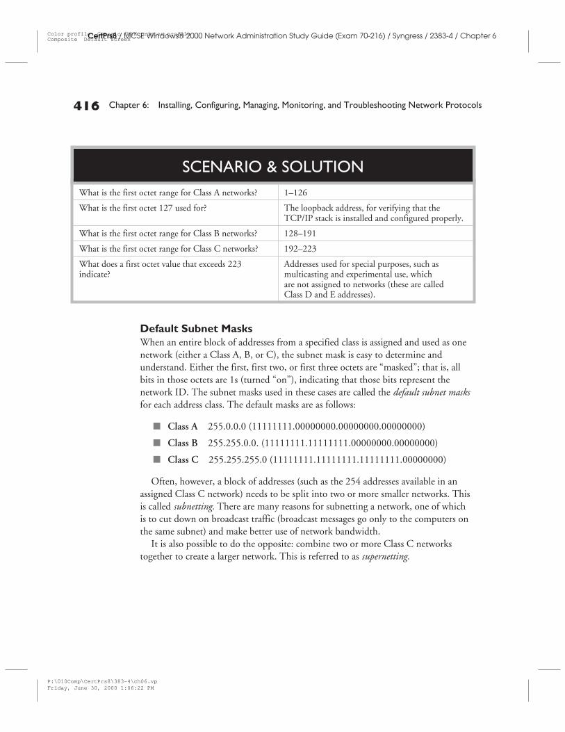
What is the first octet range for Class A networks? 1–126
What is the first octet 127 used for? The loopback address, for verifying that theTCP/IP stack is installed and configured properly.
What is the first octet range for Class B networks? 128–191
What is the first octet range for Class C networks? 192–223
What does a first octet value that exceeds 223indicate?
Addresses used for special purposes, such asmulticasting and experimental use, whichare not assigned to networks (these are calledClass D and E addresses).
SCENARIO & SOLUTION
P:\010Comp\CertPrs8\383-4\ch06.vpFriday, June 30, 2000 1:06:22 PM
Color profile: Generic CMYK printer profileComposite Default screen
IP Addressing 417
CertPrs8 / MCSE Windows® 2000 Network Administration Study Guide (Exam 70-216) / Syngress / 2383-4 / Chapter 6
Remember that the default subnet masks indicate unsubnetted networksonly when applied to the network class listed. This means the subnet mask of255.255.0.0 when applied to a Class B network indicates an unsubnetted network.However, the same mask of 255.255.0.0, if applied to a Class A network, wouldbe a subnetted network. The network class is always determined by the highorder (leftmost) bits, as discussed earlier. A common mistake for newadministrators is to assume that if the subnet mask is 255.255.255.0,for example, the network is a Class C network.
Subnetting and SupernettingBoth subnetting and supernetting are ways of modifying the IP address by “stealing”bits from one portion (network ID or host ID) to “give” to the other. To do this,you must use a variable length (or custom) subnet mask to indicate which bits in theIP address pertain to the network ID and which to the host. Routers use the subnetmask to determine to which subnetwork a data packet should be sent.
Subnetting a network turns it into a routed network, as an IP router (eithera dedicated device or a computer configured to function as a router) will berequired for computers on one subnet to communicate with the computerson other subnets.
Subnetting BasicsIf you are allocated an entire Class C network, remember that the default subnetmask is 255.255.255.0, or in binary, 11111111.11111111.11111111.00000000.
The eight bits on the right, represented as zeroes, are “yours.” You can use all ofthem for host addresses, or you can “loan” some of them to the network ID, todivide your Class C network into two or more smaller networks.
To understand variable-length subnet masks, which indicate that the network isdivided into subnets, you must work with the binary or you will probably end uphopelessly confused. Variable-length subnet masks are created by taking bits fromthe portion of the IP address normally used for the host ID and using it for the
P:\010Comp\CertPrs8\383-4\ch06.vpFriday, June 30, 2000 1:06:22 PM
Color profile: Generic CMYK printer profileComposite Default screen
network (or subnet) ID. For instance, if you borrow four bits from the host portionof a class C network address, your subnet mask will look like this:
11111111 11111111 11111111 11110000
or, in decimal:
255 255 255 240
This technique allows us to divide our Class C network into 14 usable subnetswith 14 hosts on each subnet, using the following formula:
Number of subnets = 2x -2, where x = the number of bits borrowed fromthe host ID.
Number of hosts = 2x – 2, where x = the number of unmasked host IDbits remaining.
Note that we subtract two from the number of subnets, because conventional IPsubnetting rules say we can’t have a subnet ID that is all 1s or all 0s. Thus we must“throw out” the first and last subnet IDs. We also subtract two from the number ofhosts, because two host addresses are always reserved for use as the network ID andthe broadcast address.
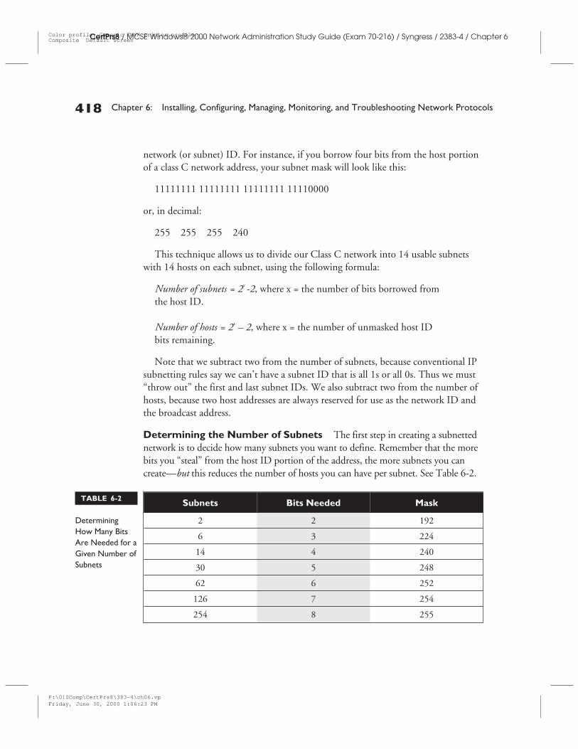
Determining the Number of Subnets The first step in creating a subnettednetwork is to decide how many subnets you want to define. Remember that the morebits you “steal” from the host ID portion of the address, the more subnets you cancreate—but this reduces the number of hosts you can have per subnet. See Table 6-2.
418 Chapter 6: Installing, Configuring, Managing, Monitoring, and Troubleshooting Network Protocols
CertPrs8 / MCSE Windows® 2000 Network Administration Study Guide (Exam 70-216) / Syngress / 2383-4 / Chapter 6
Subnets Bits Needed Mask
2 2 192
6 3 224
14 4 240
30 5 248
62 6 252
126 7 254
254 8 255
TABLE 6-2
DeterminingHow Many BitsAre Needed for aGiven Number ofSubnets
P:\010Comp\CertPrs8\383-4\ch06.vpFriday, June 30, 2000 1:06:23 PM
Color profile: Generic CMYK printer profileComposite Default screen
Table 6-2 illustrates how many new subnets can be created for each bit that you“steal” from the host ID. Use the formula 2n–2 (where n is the number of bits thatare available to be used for the host ID) to figure out the number of host addressesyou will have. Remember that Class A addresses have 24 bits minus the number ofbits used for the mask, Class B addresses have 16 bits minus the number used in themask, and Class C addresses have 8 bits minus the number used in the mask.
Determining the Mask There are three basic steps involved in determining theappropriate subnet mask:
1. Determine the number of subnets you want.
2. Convert the number to binary. Notice how many bits were required.
3. Covert the number of bits required to decimal.
About SupernettingSupernetting is a way of combining several small networks into a larger one. Forexample, a company may need a Class B network, but because those have all beenassigned, it can’t get one. However, Class C networks are available, so the companycan be assigned multiple Class C networks with contiguous addresses. By “stealing”bits again, but in the opposite direction (sort of like taking from the poor andgiving to the rich instead of vice versa), you can use some of the bits that originallyrepresented the network ID to represent host IDs, reducing the number of networksbut increasing the number of hosts available per network.
For instance, you can combine two Class C networks using a subnet mask of255.255.254.0, to provide for 512 hosts on the network instead of the 254 to whicha Class C network is traditionally limited. Or, we could combine 1024 Class Cnetworks with a subnet mask of 255.252.0.0 and obtain 262,144 host addresses(although we probably wouldn’t want to).
The addresses of the two Class C networks must be contiguous for this to work.
Supernetting often is used in conjunction with an IP addressing schemecalled CIDR.
IP Addressing 419
CertPrs8 / MCSE Windows® 2000 Network Administration Study Guide (Exam 70-216) / Syngress / 2383-4 / Chapter 6
P:\010Comp\CertPrs8\383-4\ch06.vpFriday, June 30, 2000 1:06:23 PM
Color profile: Generic CMYK printer profileComposite Default screen
Classless Addressing: CIDRThe use of address classes is the traditional way of working with IP addressing andsubnetting. A more recent development is called Classless InterDomain Routing,abbreviated as CIDR (and pronounced “cider”).
One Internet resource describes CIDR as “subnetting on steroids.” CIDRnetworks are referred to as “slash x” networks, with the “x” representing the numberof bits assigned originally as the network ID (before subnetting). Think of this as thenumber of bits that don’t “belong” to you.
With CIDR, the subnet mask actually becomes part of the routing tables. CIDRallows us to break networks into subnets and combine networks into supernets.
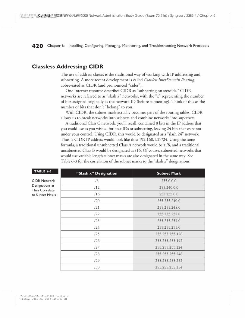
A traditional Class C network, you’ll recall, contained 8 bits in the IP address thatyou could use as you wished for host IDs or subnetting, leaving 24 bits that were notunder your control. Using CIDR, this would be designated as a “slash 24” network.Thus, a CIDR IP address would look like this: 192.168.1.27/24. Using the sameformula, a traditional unsubnetted Class A network would be a /8, and a traditionalunsubnetted Class B would be designated as /16. Of course, subnetted networks thatwould use variable length subnet masks are also designated in the same way. SeeTable 6-3 for the correlation of the subnet masks to the “slash x” designations.
420 Chapter 6: Installing, Configuring, Managing, Monitoring, and Troubleshooting Network Protocols
CertPrs8 / MCSE Windows® 2000 Network Administration Study Guide (Exam 70-216) / Syngress / 2383-4 / Chapter 6
“Slash x” Designation Subnet Mask
/8 255.0.0.0
/12 255.240.0.0
/16 255.255.0.0
/20 255.255.240.0
/21 255.255.248.0
/22 255.255.252.0
/23 255.255.254.0
/24 255.255.255.0
/25 255.255.255.128
/26 255.255.255.192
/27 255.255.255.224
/28 255.255.255.248
/29 255.255.255.252
/30 255.255.255.254
TABLE 6-3
CIDR NetworkDesignations asThey Correlateto Subnet Masks
P:\010Comp\CertPrs8\383-4\ch06.vpFriday, June 30, 2000 1:06:23 PM
Color profile: Generic CMYK printer profileComposite Default screen
CERTIFICATION OBJECTIVE 6.03
Installing, Configuring, Managing, and MonitoringTCP/IP
In order to put all this theory into practice, you must first install (if you haven’talready) and configure the TCP/IP protocol on your Windows 2000 computer.Network protocols are installed via the Network and Dial-up Connections window(this is different from NT 4.0, where you could right-click on NetworkNeighborhood and bring up the Properties sheet to install new protocols). In thiscase, you will select your local area connection, right-click, and choose Properties.
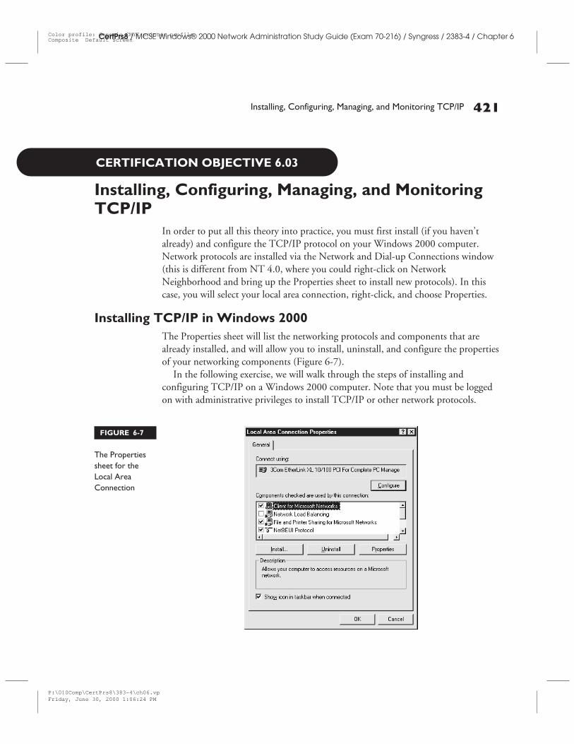
Installing TCP/IP in Windows 2000The Properties sheet will list the networking protocols and components that arealready installed, and will allow you to install, uninstall, and configure the propertiesof your networking components (Figure 6-7).
In the following exercise, we will walk through the steps of installing andconfiguring TCP/IP on a Windows 2000 computer. Note that you must be loggedon with administrative privileges to install TCP/IP or other network protocols.
Installing, Configuring, Managing, and Monitoring TCP/IP 421
CertPrs8 / MCSE Windows® 2000 Network Administration Study Guide (Exam 70-216) / Syngress / 2383-4 / Chapter 6
FIGURE 6-7
The Propertiessheet for theLocal AreaConnection
P:\010Comp\CertPrs8\383-4\ch06.vpFriday, June 30, 2000 1:06:24 PM
Color profile: Generic CMYK printer profileComposite Default screen
422 Chapter 6: Installing, Configuring, Managing, Monitoring, and Troubleshooting Network Protocols
CertPrs8 / MCSE Windows® 2000 Network Administration Study Guide (Exam 70-216) / Syngress / 2383-4 / Chapter 6
EX
ER
CIS
E6-
3
CertCam 6-3
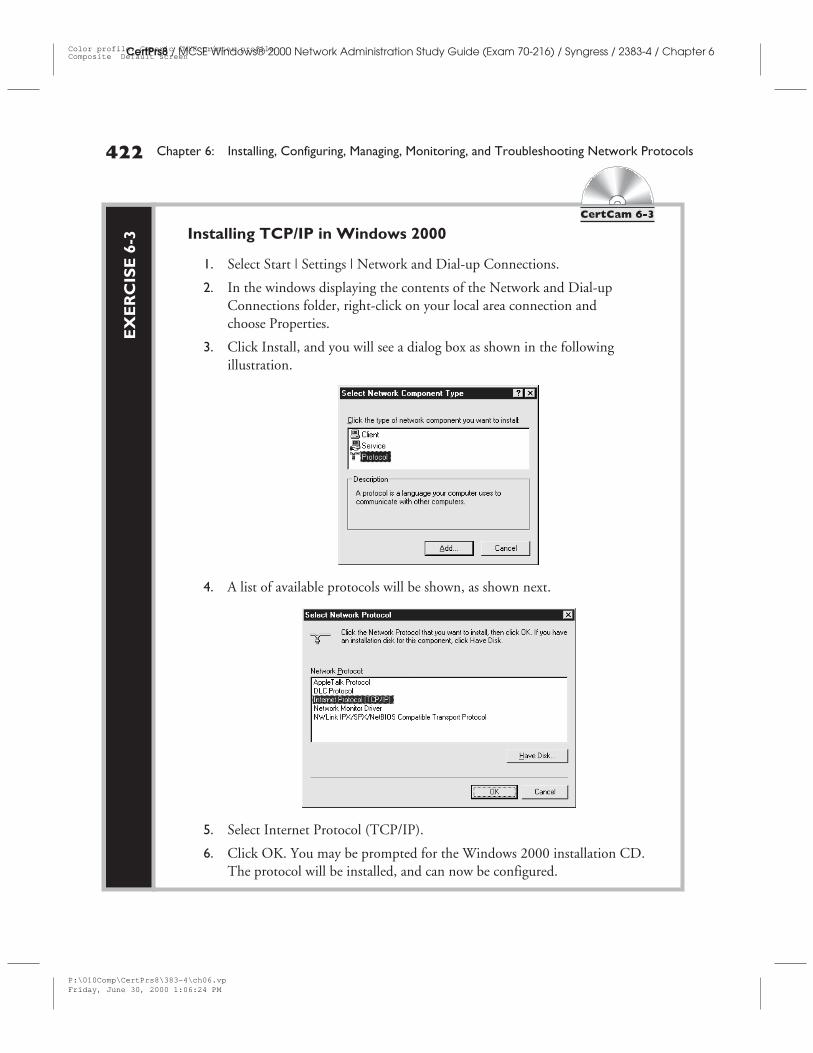
Installing TCP/IP in Windows 2000
1. Select Start | Settings | Network and Dial-up Connections.
2. In the windows displaying the contents of the Network and Dial-upConnections folder, right-click on your local area connection andchoose Properties.
3. Click Install, and you will see a dialog box as shown in the followingillustration.
4. A list of available protocols will be shown, as shown next.
5. Select Internet Protocol (TCP/IP).
6. Click OK. You may be prompted for the Windows 2000 installation CD.The protocol will be installed, and can now be configured.
P:\010Comp\CertPrs8\383-4\ch06.vpFriday, June 30, 2000 1:06:24 PM
Color profile: Generic CMYK printer profileComposite Default screen
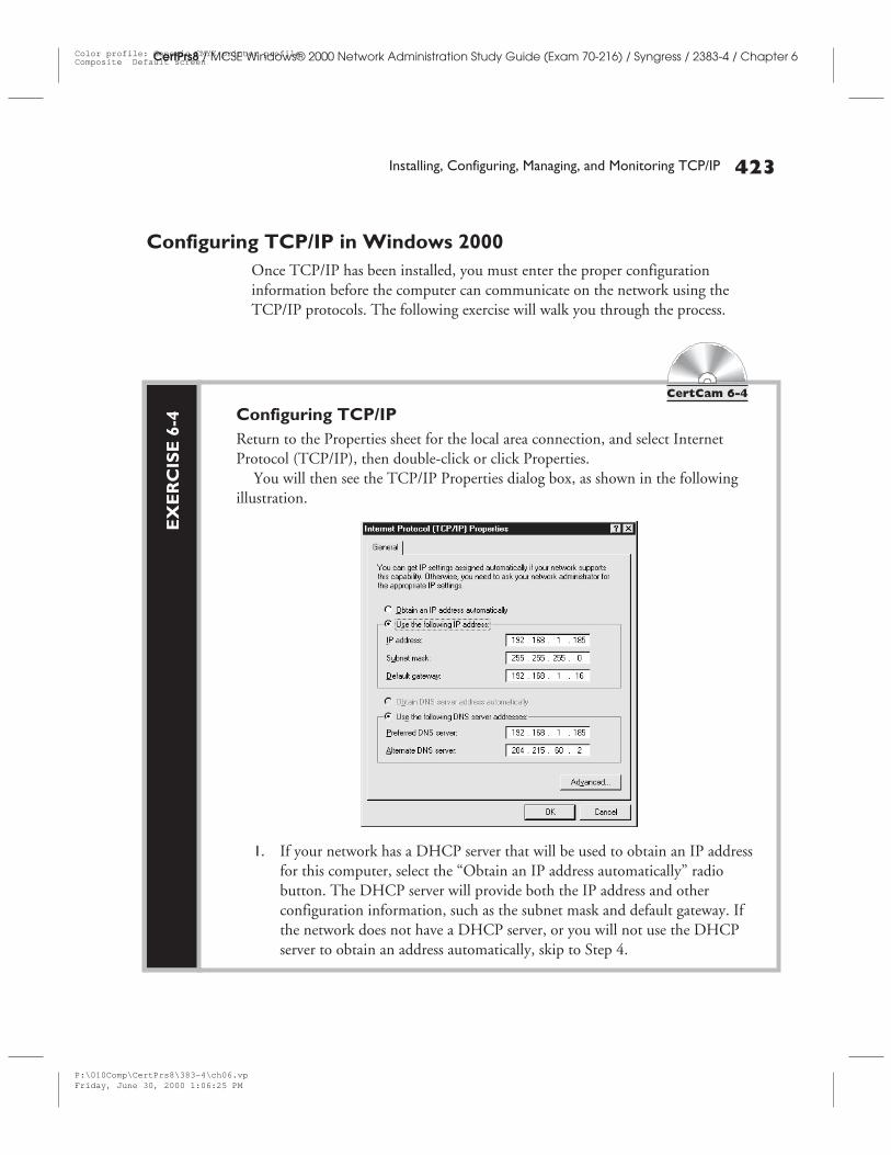
Configuring TCP/IP in Windows 2000Once TCP/IP has been installed, you must enter the proper configurationinformation before the computer can communicate on the network using theTCP/IP protocols. The following exercise will walk you through the process.
Installing, Configuring, Managing, and Monitoring TCP/IP 423
CertPrs8 / MCSE Windows® 2000 Network Administration Study Guide (Exam 70-216) / Syngress / 2383-4 / Chapter 6
EX
ER
CIS
E6-
4
CertCam 6-4
Configuring TCP/IPReturn to the Properties sheet for the local area connection, and select InternetProtocol (TCP/IP), then double-click or click Properties.
You will then see the TCP/IP Properties dialog box, as shown in the followingillustration.
1. If your network has a DHCP server that will be used to obtain an IP addressfor this computer, select the “Obtain an IP address automatically” radiobutton. The DHCP server will provide both the IP address and otherconfiguration information, such as the subnet mask and default gateway. Ifthe network does not have a DHCP server, or you will not use the DHCPserver to obtain an address automatically, skip to Step 4.
P:\010Comp\CertPrs8\383-4\ch06.vpFriday, June 30, 2000 1:06:25 PM
Color profile: Generic CMYK printer profileComposite Default screen
424 Chapter 6: Installing, Configuring, Managing, Monitoring, and Troubleshooting Network Protocols
CertPrs8 / MCSE Windows® 2000 Network Administration Study Guide (Exam 70-216) / Syngress / 2383-4 / Chapter 6
The default gateway address must be on the same subnet as the computer’sIP address.
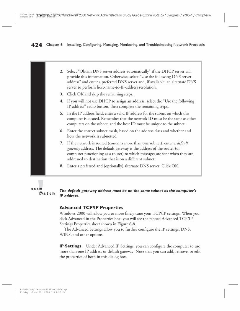
Advanced TCP/IP PropertiesWindows 2000 will allow you to more finely tune your TCP/IP settings. When youclick Advanced in the Properties box, you will see the tabbed Advanced TCP/IPSettings Properties sheet shown in Figure 6-8.
The Advanced Settings allow you to further configure the IP settings, DNS,WINS, and other options.
IP Settings Under Advanced IP Settings, you can configure the computer to usemore than one IP address or default gateway. Note that you can add, remove, or editthe properties of both in this dialog box.
2. Select “Obtain DNS server address automatically” if the DHCP server willprovide this information. Otherwise, select “Use the following DNS serveraddress” and enter a preferred DNS server and, if available, an alternate DNSserver to perform host-name-to-IP-address resolution.
3. Click OK and skip the remaining steps.
4. If you will not use DHCP to assign an address, select the “Use the followingIP address” radio button, then complete the remaining steps.
5. In the IP address field, enter a valid IP address for the subnet on which thiscomputer is located. Remember that the network ID must be the same as othercomputers on the subnet, and the host ID must be unique to the subnet.
6. Enter the correct subnet mask, based on the address class and whether andhow the network is subnetted.
7. If the network is routed (contains more than one subnet), enter a defaultgateway address. The default gateway is the address of the router (orcomputer functioning as a router) to which messages are sent when they areaddressed to destination that is on a different subnet.
8. Enter a preferred and (optionally) alternate DNS server. Click OK.
P:\010Comp\CertPrs8\383-4\ch06.vpFriday, June 30, 2000 1:06:25 PM
Color profile: Generic CMYK printer profileComposite Default screen
CertPrs8 / MCSE Windows® 2000 Network Administration Study Guide (Exam 70-216) / Syngress / 2383-4 / Chapter 6
Assigning Multiple IP Addresses You can use multiple IP addresses invarious situations, such as public addresses used for the Internet and privateaddresses used for an internal network, or for multiple logical IP networks on thesame physical network segment.
Assigning Multiple Default Gateways Windows 2000 supports a featurecalled dead gateway detection, which is used to detect routers that have gone down. Ifmultiple default gateways are configured, a failing TCP connection will update the IProuting table with the next default gateway in the list. Although you can assign multiplegateways, the second (or subsequent) gateway(s) will be used only if the first fails. Inother words, more than one default gateway cannot be active simultaneously.
The Interface Metric You can specify a custom metric for the connection bytyping a value in this field (the default value is 1). A metric is the cost of using aparticular route from one destination to another. Generally this will be the numberof hops to the IP destination. Anything on the local subnet is one hop, and everytime a router is crossed, this adds 1 to the hop count. The value of this is that it letsWindows 2000 select the route with the lowest metric if there are multiple routes tothe same destination.
Installing, Configuring, Managing, and Monitoring TCP/IP 425
CertPrs8 / MCSE Windows® 2000 Network Administration Study Guide (Exam 70-216) / Syngress / 2383-4 / Chapter 6
FIGURE 6-8
The AdvancedTCP/IP SettingsProperty sheet
P:\010Comp\CertPrs8\383-4\ch06.vpFriday, June 30, 2000 1:06:25 PM
Color profile: Generic CMYK printer profileComposite Default screen
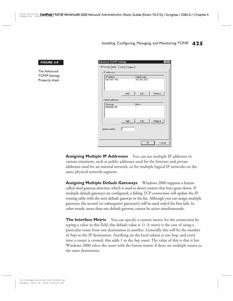
Advanced DNS Settings The DNS tab on the Advanced Settings sheet isshown in Figure 6-9.
You can configure the following Advanced settings for DNS:
■ Multiple DNS servers If there are multiple DNS servers configured on thenetwork, and TCP/IP doesn’t receive any response from the current DNSserver, the next DNS server will be used.
■ Unqualified name resolution You can configure TCP/IP to resolveunqualified names by either (1) appending the primary and connection- specificDNS suffixes to the unqualified name for DNS queries, or (2) appending a seriesof configured DNS suffixes to the unqualified name for DNS queries.
■ Connection-specific DNS suffixes Each connection in the Network andDial-up Connections can be set up to have its own DNS suffix, along withthe primary DNS suffix that is configured for the computer on the NetworkIdentification tab in the System applet (in Control Panel).
426 Chapter 6: Installing, Configuring, Managing, Monitoring, and Troubleshooting Network Protocols
CertPrs8 / MCSE Windows® 2000 Network Administration Study Guide (Exam 70-216) / Syngress / 2383-4 / Chapter 6
FIGURE 6-9
You can fine-tuneDNS settingswith theAdvancedSettings Propertysheet
P:\010Comp\CertPrs8\383-4\ch06.vpFriday, June 30, 2000 1:06:26 PM
Color profile: Generic CMYK printer profileComposite Default screen
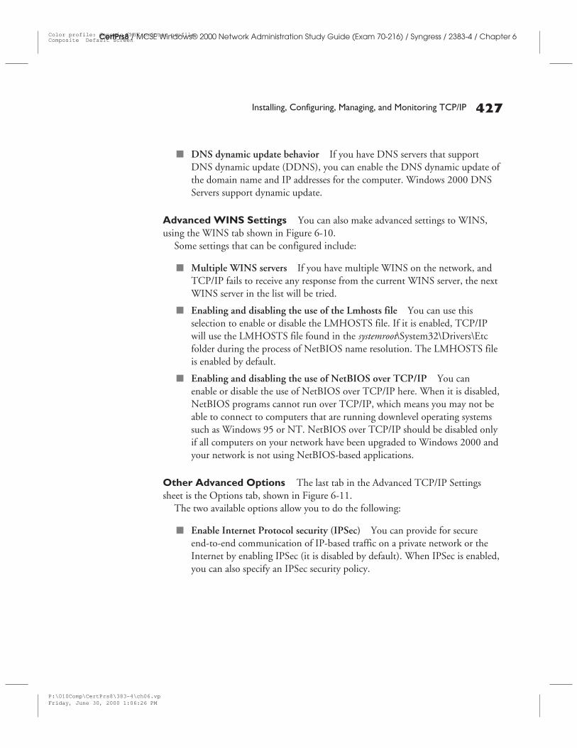
Installing, Configuring, Managing, and Monitoring TCP/IP 427
CertPrs8 / MCSE Windows® 2000 Network Administration Study Guide (Exam 70-216) / Syngress / 2383-4 / Chapter 6
■ DNS dynamic update behavior If you have DNS servers that supportDNS dynamic update (DDNS), you can enable the DNS dynamic update ofthe domain name and IP addresses for the computer. Windows 2000 DNSServers support dynamic update.
Advanced WINS Settings You can also make advanced settings to WINS,using the WINS tab shown in Figure 6-10.
Some settings that can be configured include:
■ Multiple WINS servers If you have multiple WINS on the network, andTCP/IP fails to receive any response from the current WINS server, the nextWINS server in the list will be tried.
■ Enabling and disabling the use of the Lmhosts file You can use thisselection to enable or disable the LMHOSTS file. If it is enabled, TCP/IPwill use the LMHOSTS file found in the systemroot\System32\Drivers\Etcfolder during the process of NetBIOS name resolution. The LMHOSTS fileis enabled by default.
■ Enabling and disabling the use of NetBIOS over TCP/IP You canenable or disable the use of NetBIOS over TCP/IP here. When it is disabled,NetBIOS programs cannot run over TCP/IP, which means you may not beable to connect to computers that are running downlevel operating systemssuch as Windows 95 or NT. NetBIOS over TCP/IP should be disabled onlyif all computers on your network have been upgraded to Windows 2000 andyour network is not using NetBIOS-based applications.
Other Advanced Options The last tab in the Advanced TCP/IP Settingssheet is the Options tab, shown in Figure 6-11.
The two available options allow you to do the following:
■ Enable Internet Protocol security (IPSec) You can provide for secureend-to-end communication of IP-based traffic on a private network or theInternet by enabling IPSec (it is disabled by default). When IPSec is enabled,you can also specify an IPSec security policy.
P:\010Comp\CertPrs8\383-4\ch06.vpFriday, June 30, 2000 1:06:26 PM
Color profile: Generic CMYK printer profileComposite Default screen
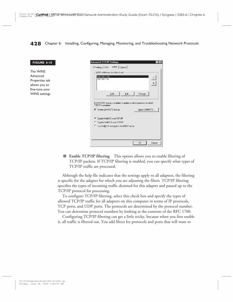
428 Chapter 6: Installing, Configuring, Managing, Monitoring, and Troubleshooting Network Protocols
CertPrs8 / MCSE Windows® 2000 Network Administration Study Guide (Exam 70-216) / Syngress / 2383-4 / Chapter 6
■ Enable TCP/IP filtering This option allows you to enable filtering ofTCP/IP packets. If TCP/IP filtering is enabled, you can specify what types ofTCP/IP traffic are processed.
Although the help file indicates that the settings apply to all adapters, the filteringis specific for the adapter for which you are adjusting the filters. TCP/IP filteringspecifies the types of incoming traffic destined for this adapter and passed up to theTCP/IP protocol for processing.
To configure TCP/IP filtering, select this check box and specify the types ofallowed TCP/IP traffic for all adapters on this computer in terms of IP protocols,TCP ports, and UDP ports. The protocols are determined by the protocol number.You can determine protocol numbers by looking at the contents of the RFC 1700.
Configuring TCP/IP filtering can get a little tricky, because when you first enableit, all traffic is filtered out. You add filters for protocols and ports that will want to
FIGURE 6-10
The WINSAdvancedProperties taballows you tofine-tune yourWINS settings
P:\010Comp\CertPrs8\383-4\ch06.vpFriday, June 30, 2000 1:06:27 PM
Color profile: Generic CMYK printer profileComposite Default screen
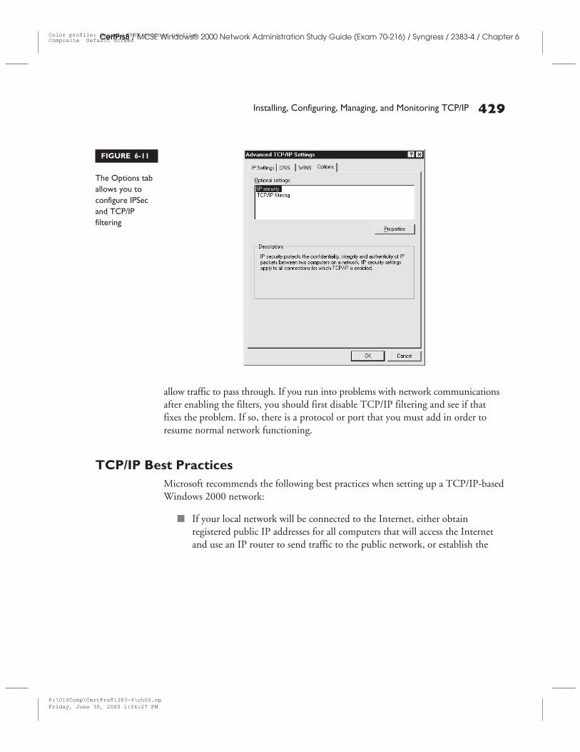
Installing, Configuring, Managing, and Monitoring TCP/IP 429
CertPrs8 / MCSE Windows® 2000 Network Administration Study Guide (Exam 70-216) / Syngress / 2383-4 / Chapter 6
allow traffic to pass through. If you run into problems with network communicationsafter enabling the filters, you should first disable TCP/IP filtering and see if thatfixes the problem. If so, there is a protocol or port that you must add in order toresume normal network functioning.
TCP/IP Best PracticesMicrosoft recommends the following best practices when setting up a TCP/IP-basedWindows 2000 network:
■ If your local network will be connected to the Internet, either obtainregistered public IP addresses for all computers that will access the Internetand use an IP router to send traffic to the public network, or establish the
FIGURE 6-11
The Options taballows you toconfigure IPSecand TCP/IPfiltering
P:\010Comp\CertPrs8\383-4\ch06.vpFriday, June 30, 2000 1:06:27 PM
Color profile: Generic CMYK printer profileComposite Default screen
Internet connection using one computer, install Network Address Translation(NAT) on that computer, assign private (nonregistered) IP addresses to theother computers on the internal network, and let NAT translate the privateaddresses to the public address to provide access to the Internet for all thecomputers on the LAN.
■ If you assign private addresses, use the address ranges in each class that aredesignated as reserved for that purpose by IANA.
Troubleshooting TCP/IPTCP/IP is a powerful, flexible, and reliable protocol suite. Generally it works well,but because it is so complex, there are many ways in which it can be misconfiguredor, for other reasons, fail to provide network communications.
Troubleshooting TCP/IP is thus a complicated topic, and an entire book couldbe written about it (and in fact, several have been). This chapter can only touch onthe basics of TCP/IP troubleshooting. For more detailed information, see our bookTroubleshooting Windows 2000 TCP/IP by Debra Littlejohn Shinder and ThomasW. Shinder, published by Syngress Media.
Windows 2000 TCP/IP comes with several useful utilities that can provide youwith valuable troubleshooting information and help you to diagnose the problemwhen your TCP/IP network experiences connectivity problems. These includethe command-line utilities IPCONFIG, PING/PATHPING, TRACERT,and NETSTAT/NBTSTAT, as well as Windows 2000’s protocol analysis tool,Network Monitor.
Using TCP/IP UtilitiesThe command-line utilities included with Windows 2000 are useful in identifyingand resolving TCP/IP problems.
IPCONFIG This utility displays current TCP/IP configuration values, andcan be used to manually release and renew (with the /release and /renew switches,respectively) a TCP/IP configuration lease assigned by a DHCP server. It can alsobe used to reset DNS name registrations with the /registerdns switch. TypingIPCONFIG provides basic configuration information: IP address, subnet mask,and default gateway. Typing IPCONFIG /ALL provides more detailed information,as shown in Figure 6-12.
CertPrs8 / MCSE Windows® 2000 Network Administration Study Guide (Exam 70-216) / Syngress / 2383-4 / Chapter 6
430 Chapter 6: Installing, Configuring, Managing, Monitoring, and Troubleshooting Network Protocols
P:\010Comp\CertPrs8\383-4\ch06.vpFriday, June 30, 2000 1:06:27 PM
Color profile: Generic CMYK printer profileComposite Default screen
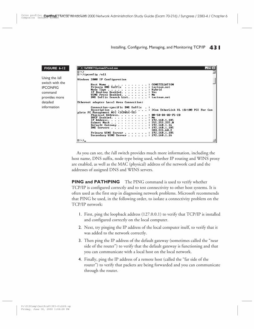
Installing, Configuring, Managing, and Monitoring TCP/IP 431
CertPrs8 / MCSE Windows® 2000 Network Administration Study Guide (Exam 70-216) / Syngress / 2383-4 / Chapter 6
As you can see, the /all switch provides much more information, including thehost name, DNS suffix, node type being used, whether IP routing and WINS proxyare enabled, as well as the MAC (physical) address of the network card and theaddresses of assigned DNS and WINS servers.
PING and PATHPING The PING command is used to verify whetherTCP/IP is configured correctly and to test connectivity to other host systems. It isoften used as the first step in diagnosing network problems. Microsoft recommendsthat PING be used, in the following order, to isolate a connectivity problem on theTCP/IP network:
1. First, ping the loopback address (127.0.0.1) to verify that TCP/IP is installedand configured correctly on the local computer.
2. Next, try pinging the IP address of the local computer itself, to verify that itwas added to the network correctly.
3. Then ping the IP address of the default gateway (sometimes called the “nearside of the router”) to verify that the default gateway is functioning and thatyou can communicate with a local host on the local network.
4. Finally, ping the IP address of a remote host (called the “far side of therouter”) to verify that packets are being forwarded and you can communicatethrough the router.
FIGURE 6-12
Using the /allswitch with theIPCONFIGcommandprovides moredetailedinformation
P:\010Comp\CertPrs8\383-4\ch06.vpFriday, June 30, 2000 1:06:28 PM
Color profile: Generic CMYK printer profileComposite Default screen
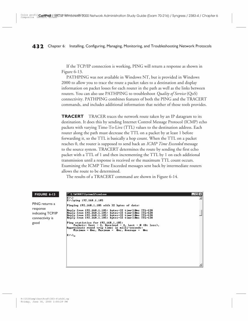
If the TCP/IP connection is working, PING will return a response as shown inFigure 6-13.
PATHPING was not available in Windows NT, but is provided in Windows2000 to allow you to trace the route a packet takes to a destination and displayinformation on packet losses for each router in the path as well as the links betweenrouters. You can also use PATHPING to troubleshoot Quality of Service (QoS)connectivity. PATHPING combines features of both the PING and the TRACERTcommands, and includes additional information that neither of those tools provides.
TRACERT TRACER traces the network route taken by an IP datagram to itsdestination. It does this by sending Internet Control Message Protocol (ICMP) echopackets with varying Time-To-Live (TTL) values to the destination address. Eachrouter along the path must decrease the TTL on a packet by at least 1 beforeforwarding it, so the TTL is basically a hop count. When the TTL on a packetreaches 0, the router is supposed to send back an ICMP Time Exceeded messageto the source system. TRACERT determines the route by sending the first echopacket with a TTL of 1 and then incrementing the TTL by 1 on each additionaltransmission until a response is received or the maximum TTL count occurs.Examining the ICMP Time Exceeded messages sent back by intermediate routersallows the route to be determined.
The results of a TRACERT command are shown in Figure 6-14.
432 Chapter 6: Installing, Configuring, Managing, Monitoring, and Troubleshooting Network Protocols
CertPrs8 / MCSE Windows® 2000 Network Administration Study Guide (Exam 70-216) / Syngress / 2383-4 / Chapter 6
FIGURE 6-13
PING returns aresponseindicating TCP/IPconnectivity isgood
P:\010Comp\CertPrs8\383-4\ch06.vpFriday, June 30, 2000 1:06:29 PM
Color profile: Generic CMYK printer profileComposite Default screen
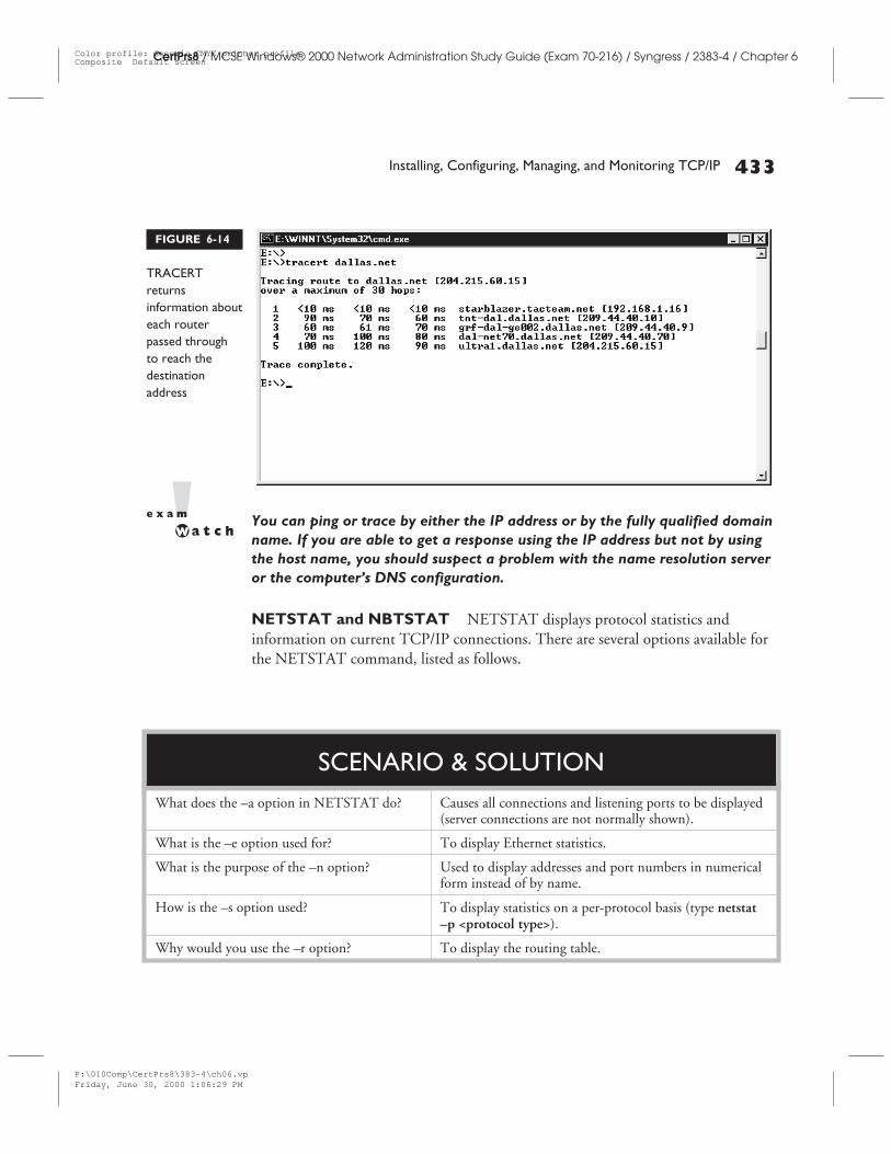
You can ping or trace by either the IP address or by the fully qualified domainname. If you are able to get a response using the IP address but not by usingthe host name, you should suspect a problem with the name resolution serveror the computer’s DNS configuration.
NETSTAT and NBTSTAT NETSTAT displays protocol statistics andinformation on current TCP/IP connections. There are several options available forthe NETSTAT command, listed as follows.
Installing, Configuring, Managing, and Monitoring TCP/IP 433
CertPrs8 / MCSE Windows® 2000 Network Administration Study Guide (Exam 70-216) / Syngress / 2383-4 / Chapter 6
FIGURE 6-14
TRACERTreturnsinformation abouteach routerpassed throughto reach thedestinationaddress
What does the –a option in NETSTAT do? Causes all connections and listening ports to be displayed(server connections are not normally shown).
What is the –e option used for? To display Ethernet statistics.
What is the purpose of the –n option? Used to display addresses and port numbers in numericalform instead of by name.
How is the –s option used? To display statistics on a per-protocol basis (type netstat–p <protocol type>).
Why would you use the –r option? To display the routing table.
SCENARIO & SOLUTION
P:\010Comp\CertPrs8\383-4\ch06.vpFriday, June 30, 2000 1:06:29 PM
Color profile: Generic CMYK printer profileComposite Default screen
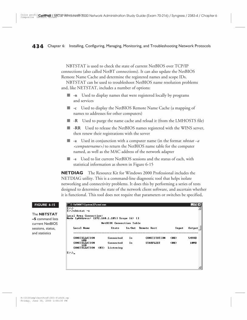
NBTSTAT is used to check the state of current NetBIOS over TCP/IPconnections (also called NetBT connections). It can also update the NetBIOSRemote Name Cache and determine the registered names and scope IDs.
NBTSTAT can be used to troubleshoot NetBIOS name resolution problemsand, like NETSTAT, includes a number of options:
■ -n Used to display names that were registered locally by programsand services
■ -c Used to display the NetBIOS Remote Name Cache (a mapping ofnames to addresses for other computers)
■ -R Used to purge the name cache and reload it (from the LMHOSTS file)
■ -RR Used to release the NetBIOS names registered with the WINS server,then renew their registrations with the server
■ -a Used in conjunction with a computer name (in the format nbtstat –a<computername>) to return the NetBIOS name table for the computernamed, as well as the MAC address of the network adapter
■ -s Used to list current NetBIOS sessions and the status of each, withstatistical information as shown in Figure 6-15
NETDIAG The Resource Kit for Windows 2000 Professional includes theNETDIAG utility. This is a command-line diagnostic tool that helps isolatenetworking and connectivity problems. It does this by performing a series of testsdesigned to determine the state of the network client software, and ascertain whetherit is functional. This tool does not require that parameters or switches be specified,
434 Chapter 6: Installing, Configuring, Managing, Monitoring, and Troubleshooting Network Protocols
CertPrs8 / MCSE Windows® 2000 Network Administration Study Guide (Exam 70-216) / Syngress / 2383-4 / Chapter 6
FIGURE 6-15
The NBTSTAT–S command listscurrent NetBIOSsessions, status,and statistics
P:\010Comp\CertPrs8\383-4\ch06.vpFriday, June 30, 2000 1:06:30 PM
Color profile: Generic CMYK printer profileComposite Default screen
Installing, Configuring, Managing, and Monitoring TCP/IP 435
CertPrs8 / MCSE Windows® 2000 Network Administration Study Guide (Exam 70-216) / Syngress / 2383-4 / Chapter 6
which means support personnel and network administrators can focus on analyzingthe output, rather than training users on how to use the tool.
The resource kits for both Windows 2000 Professional and Server containmany useful tools for isolating, diagnosing, and sometimes even fixingproblems. It is an excellent idea to familiarize yourself with the tools includedin the resource kits, as well as those that ship with the product. Third partiesalso provide a variety of troubleshooting utilities for Windows 2000.
Managing and Monitoring Network TrafficBecause TCP/IP is such a widely used set of protocols, there are numerous hardwareand software tools available for monitoring and managing traffic on a TCP/IPnetwork. You can practice preventative maintenance, establish baselines, ortroubleshoot existing problems. One of the most popular types of tools is called aprotocol analyzer. This is usually a software program that allows you to copy theindividual packets and analyze their structure. The process of copying frames forreview and analysis is called capturing.
Windows 2000 Server includes a “lite” version of the protocol monitor thatcomes with Systems Management Server (SMS), Network Monitor. This tool canbe used to capture and display the frames or packets that a Windows 2000 Serverreceives from a LAN. You can use Network Monitor to detect and troubleshootmany networking problems.
Installing the Windows 2000 Network MonitorThe Network Monitor tool can be installed on Windows 2000 Server from theAdd/Remove Programs applet in Control Panel. Open the applet and click onAdd/Remove Windows Components, select Management and Monitoring Tools,and then click Details. Select the Network Monitor check box. You may beprompted to insert your Windows 2000 installation CD.
After installation is complete, the Network Monitor will appear in theAdministrative Tools submenu of the Programs menu.
Using the Windows 2000 Network MonitorThe version of Network Monitor included in Windows 2000 has some limitations.It cannot run in what is referred to as promiscuous mode. This is a state in which thenetwork card can listen to all the traffic on the network, not just that which is sentfrom or received by the computer running the Network Monitor software. Themore sophisticated version of Network Monitor that comes with SMS is capable of
P:\010Comp\CertPrs8\383-4\ch06.vpFriday, June 30, 2000 1:06:30 PM
Color profile: Generic CMYK printer profileComposite Default screen
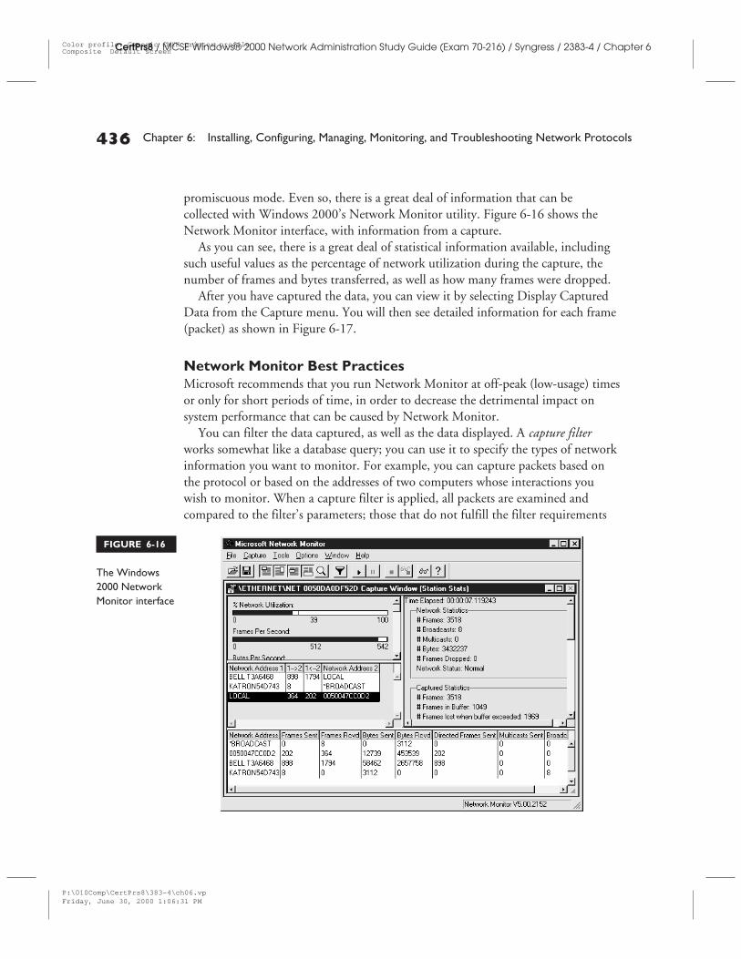
promiscuous mode. Even so, there is a great deal of information that can becollected with Windows 2000’s Network Monitor utility. Figure 6-16 shows theNetwork Monitor interface, with information from a capture.
As you can see, there is a great deal of statistical information available, includingsuch useful values as the percentage of network utilization during the capture, thenumber of frames and bytes transferred, as well as how many frames were dropped.
After you have captured the data, you can view it by selecting Display CapturedData from the Capture menu. You will then see detailed information for each frame(packet) as shown in Figure 6-17.
Network Monitor Best PracticesMicrosoft recommends that you run Network Monitor at off-peak (low-usage) timesor only for short periods of time, in order to decrease the detrimental impact onsystem performance that can be caused by Network Monitor.
You can filter the data captured, as well as the data displayed. A capture filterworks somewhat like a database query; you can use it to specify the types of networkinformation you want to monitor. For example, you can capture packets based onthe protocol or based on the addresses of two computers whose interactions youwish to monitor. When a capture filter is applied, all packets are examined andcompared to the filter’s parameters; those that do not fulfill the filter requirements
436 Chapter 6: Installing, Configuring, Managing, Monitoring, and Troubleshooting Network Protocols
CertPrs8 / MCSE Windows® 2000 Network Administration Study Guide (Exam 70-216) / Syngress / 2383-4 / Chapter 6
FIGURE 6-16
The Windows2000 NetworkMonitor interface
P:\010Comp\CertPrs8\383-4\ch06.vpFriday, June 30, 2000 1:06:31 PM
Color profile: Generic CMYK printer profileComposite Default screen
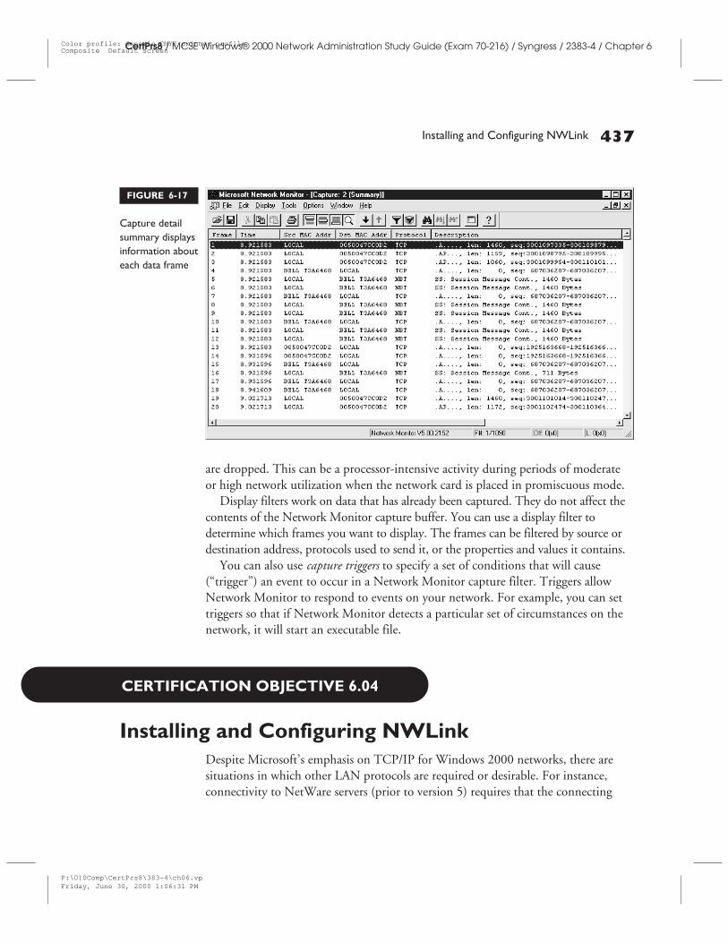
Installing and Configuring NWLink 437
CertPrs8 / MCSE Windows® 2000 Network Administration Study Guide (Exam 70-216) / Syngress / 2383-4 / Chapter 6
are dropped. This can be a processor-intensive activity during periods of moderateor high network utilization when the network card is placed in promiscuous mode.
Display filters work on data that has already been captured. They do not affect thecontents of the Network Monitor capture buffer. You can use a display filter todetermine which frames you want to display. The frames can be filtered by source ordestination address, protocols used to send it, or the properties and values it contains.
You can also use capture triggers to specify a set of conditions that will cause(“trigger”) an event to occur in a Network Monitor capture filter. Triggers allowNetwork Monitor to respond to events on your network. For example, you can settriggers so that if Network Monitor detects a particular set of circumstances on thenetwork, it will start an executable file.
CERTIFICATION OBJECTIVE 6.04
Installing and Configuring NWLinkDespite Microsoft’s emphasis on TCP/IP for Windows 2000 networks, there aresituations in which other LAN protocols are required or desirable. For instance,connectivity to NetWare servers (prior to version 5) requires that the connecting
FIGURE 6-17
Capture detailsummary displaysinformation abouteach data frame
P:\010Comp\CertPrs8\383-4\ch06.vpFriday, June 30, 2000 1:06:31 PM
Color profile: Generic CMYK printer profileComposite Default screen
computer(s) be running an IPX/SPX protocol stack. NWLink is Microsoft’simplementation of IPX/SPX (the Internetwork Packet Exchange/Sequenced PacketExchange protocols). You can install NWLink on Windows 2000 machines to allowthem to access NetWare servers.
Be aware that although NWLink and IPX/SPX are often thought of inMicrosoft networking circles as “the protocols used to connect to NetWarenetworks,” you can also use these protocols to connect Windows machines toone another. Because NWLink is faster and easier to configure than TCP/IPand routable (unlike NetBEUI), it can be an appropriate LAN protocol choicefor a small or medium network that is not connected to the Internet, even ifthere are no NetWare servers anywhere in sight.
Installing the NWLink ProtocolNWLink is installed in the same way as TCP/IP, through the Network and Dial-upConnections properties box. Note that you must be logged on with administrativeprivileges to install NWLink or other network protocols.
When you install the NWLink protocols, they will be installed on all yournetwork connections. However, you can change this. After the installation iscompleted, if you do not want to use NWLink on a particular connection,you can right-click that connection, click Properties and uncheck the NWLinkIPX/SPX/NetBIOS Compatible Transport Protocol check box on either theGeneral or Networking tab.
Configuring NWLinkThere is less configuration information required to set up NWLink than is necessaryfor TCP/IP, but there are still a few pieces of information you will need to have onhand. The configuration box asks you for a network number; if you are uncertain ofthis number, the default value of 00000000 will usually work.
Another setting that can be configured is the frame type. You can use automaticframe type detection, however. In most cases, this is preferred.
You can use the IPXROUTE CONFIG command to get information about theinternal network number being used by the routers on the network, as well as theframe type being used by the servers.
438 Chapter 6: Installing, Configuring, Managing, Monitoring, and Troubleshooting Network Protocols
CertPrs8 / MCSE Windows® 2000 Network Administration Study Guide (Exam 70-216) / Syngress / 2383-4 / Chapter 6
P:\010Comp\CertPrs8\383-4\ch06.vpFriday, June 30, 2000 1:06:32 PM
Color profile: Generic CMYK printer profileComposite Default screen
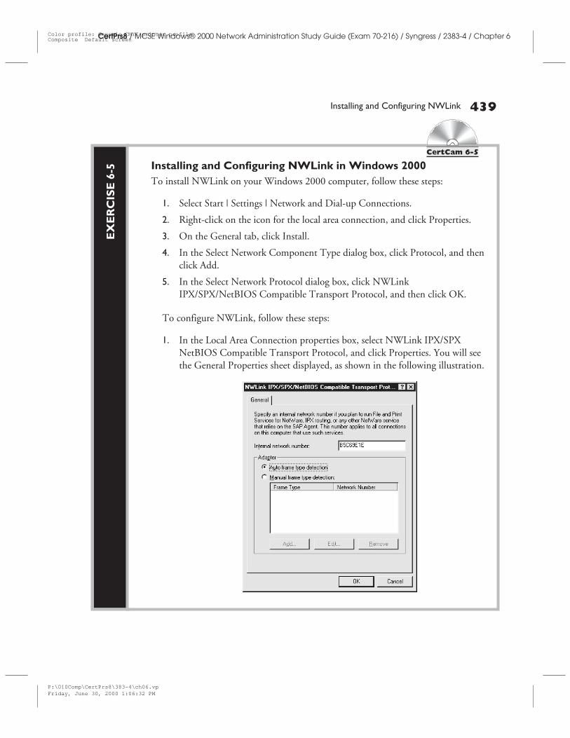
Installing and Configuring NWLink 439
CertPrs8 / MCSE Windows® 2000 Network Administration Study Guide (Exam 70-216) / Syngress / 2383-4 / Chapter 6
EX
ER
CIS
E6-
5
CertCam 6-5
Installing and Configuring NWLink in Windows 2000To install NWLink on your Windows 2000 computer, follow these steps:
1. Select Start | Settings | Network and Dial-up Connections.
2. Right-click on the icon for the local area connection, and click Properties.
3. On the General tab, click Install.
4. In the Select Network Component Type dialog box, click Protocol, and thenclick Add.
5. In the Select Network Protocol dialog box, click NWLinkIPX/SPX/NetBIOS Compatible Transport Protocol, and then click OK.
To configure NWLink, follow these steps:
1. In the Local Area Connection properties box, select NWLink IPX/SPXNetBIOS Compatible Transport Protocol, and click Properties. You will seethe General Properties sheet displayed, as shown in the following illustration.
P:\010Comp\CertPrs8\383-4\ch06.vpFriday, June 30, 2000 1:06:32 PM
Color profile: Generic CMYK printer profileComposite Default screen
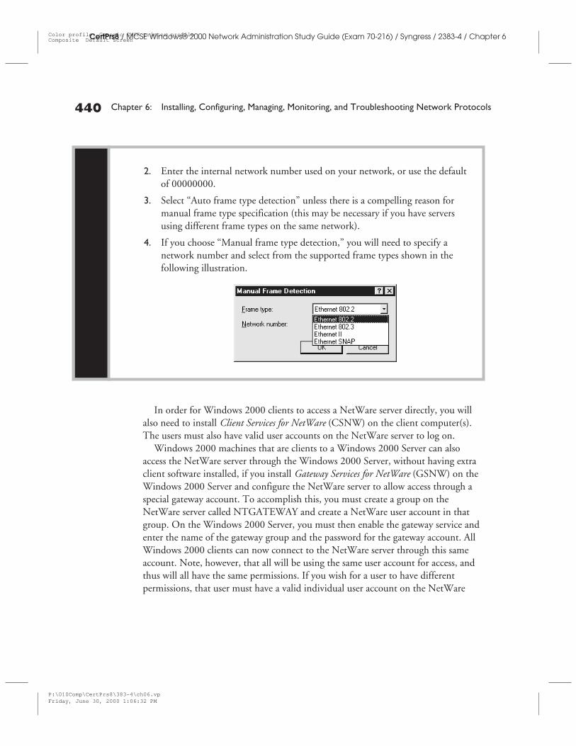
In order for Windows 2000 clients to access a NetWare server directly, you willalso need to install Client Services for NetWare (CSNW) on the client computer(s).The users must also have valid user accounts on the NetWare server to log on.
Windows 2000 machines that are clients to a Windows 2000 Server can alsoaccess the NetWare server through the Windows 2000 Server, without having extraclient software installed, if you install Gateway Services for NetWare (GSNW) on theWindows 2000 Server and configure the NetWare server to allow access through aspecial gateway account. To accomplish this, you must create a group on theNetWare server called NTGATEWAY and create a NetWare user account in thatgroup. On the Windows 2000 Server, you must then enable the gateway service andenter the name of the gateway group and the password for the gateway account. AllWindows 2000 clients can now connect to the NetWare server through this sameaccount. Note, however, that all will be using the same user account for access, andthus will all have the same permissions. If you wish for a user to have differentpermissions, that user must have a valid individual user account on the NetWare
440 Chapter 6: Installing, Configuring, Managing, Monitoring, and Troubleshooting Network Protocols
CertPrs8 / MCSE Windows® 2000 Network Administration Study Guide (Exam 70-216) / Syngress / 2383-4 / Chapter 6
2. Enter the internal network number used on your network, or use the defaultof 00000000.
3. Select “Auto frame type detection” unless there is a compelling reason formanual frame type specification (this may be necessary if you have serversusing different frame types on the same network).
4. If you choose “Manual frame type detection,” you will need to specify anetwork number and select from the supported frame types shown in thefollowing illustration.
P:\010Comp\CertPrs8\383-4\ch06.vpFriday, June 30, 2000 1:06:32 PM
Color profile: Generic CMYK printer profileComposite Default screen
server through which he or she can access the server’s resources and client softwareinstalled on the client machine.
Protocol Binding OrderNetwork protocols are bound to network services installed on a particular client orserver. Multiple protocols can be bound to multiple network services. For example,you can bind NetBEUI, TCP/IP, and NWLink to the Microsoft network client.
When a client attempts to establish a session with a server, it will request to usethe protocol on the top of its binding order for the particular service. If the serviceis the Microsoft Network Client, then the protocol binding order for that list isprocessed. Just as was the case with Windows NT 4.0, the client determines thepreferred protocol.
For example, the Microsoft network client service on the client has NetBEUI andTCP/IP installed, with NetBEUI on the top of the binding order. The destinationserver also has NetBEUI and TCP/IP installed, but has TCP/IP on top of thebinding order. Since the caller determines the binding order, they will negotiateusing TCP/IP first, because that is on top of the client’s binding order.
To change the binding order you must open the Network and Dial-upConnections folder first. After opening the folder, click on the Advanced menuand click Advanced Settings. On the Adapters and Bindings tab, you will beable to use the UP and DOWN arrows to change the binding order.
CERTIFICATION SUMMARYThis chapter has covered a wide scope of topics pertaining to the networkingprotocols used for communication by the Windows 2000 operating systems,particularly the members of the TCP/IP protocol suite. In fact, we started thechapter with an introduction to the Windows 2000 implementation of TCP/IP anda brief history of the protocols, discussed the advantages and disadvantages ofTCP/IP and where it fits into the popular networking models, the Open SystemsInterconnection (OSI) model and the Department of Defense (DoD) model.
TCP/IP is the protocol stack of the global Internet, so we discussed the growth ofthe Internet and how TCP/IP played a part in that growth. We talked about IP
Installing and Configuring NWLink 441
CertPrs8 / MCSE Windows® 2000 Network Administration Study Guide (Exam 70-216) / Syngress / 2383-4 / Chapter 6
P:\010Comp\CertPrs8\383-4\ch06.vpFriday, June 30, 2000 1:06:33 PM
Color profile: Generic CMYK printer profileComposite Default screen
addressing, including subnetting and supernetting, and we walked through anexercise on how to install and configure the TCP/IP protocols in Windows 2000.
Then we briefly discussed troubleshooting TCP/IP connectivity problems, andsome of the tools and utilities included in Windows 2000 or available elsewhere thatmake troubleshooting easier. We examined the Network Monitor protocol analysistool that Windows 2000 includes, and learned how to install it and how to use it tocapture packets on the network.
Finally, we turned our attention to another popular protocol stack, IPX/SPX,which is used in many NetWare networks and is implemented in Windows 2000 asNWLink. We completed an exercise in installing and configuring NWLink, and wediscussed the services—Client Services for NetWare and Gateway Services forNetWare—that are used, along with the NWLink protocols, to allow Windows2000 machines to connect to and access the resources of NetWare servers.
442 Chapter 6: Installing, Configuring, Managing, Monitoring, and Troubleshooting Network Protocols
CertPrs8 / MCSE Windows® 2000 Network Administration Study Guide (Exam 70-216) / Syngress / 2383-4 / Chapter 6
P:\010Comp\CertPrs8\383-4\ch06.vpFriday, June 30, 2000 1:06:33 PM
Color profile: Generic CMYK printer profileComposite Default screen
✓TWO-MINUTE DRILL
Windows 2000 TCP/IP❑ TCP/IP is the default network transport protocol in Windows 2000, and is
required for connectivity to the Internet.
❑ The TCP/IP protocol suite is relatively slow and difficult to configure, buthas the advantages over NWLink and NetBEUI of a flexible, scalableaddressing scheme, compatibility with many platforms and operatingsystems, and routability.
❑ The TCP/IP suite consists of many different protocols that operate atdifferent layers of the networking model, including IP, ICMP and IGMP,ARP/RARP, TCP, UDP, FTP, Telnet, SMTP, SNMP, and others.
IP Addressing❑ IP addresses are 32-bit binary numbers (often expressed as their dotted
decimal equivalent), in which one portion represents the network ID and theother portion represents the host ID.
❑ The subnet mask is a 32-bit binary number used to indicate which bits in theIP address represent the network and which represent the host.
❑ IP networks were traditionally divided into three classes: Class A for largenetworks, Class B for medium-sized networks, and Class C for smallnetworks.
❑ Classless InterDomain Routing (CIDR) is a newer method of allocatingaddresses to networks that does not use the class system, but instead appendsa “slash x” number to the end of the IP address that indicates how many bitsare used for the network ID.
❑ Subnetting is a method of “stealing” bits from the designated host ID andadding them to the network ID in order to create more networks, but withfewer hosts each.
❑ Supernetting is a method of combining two or more smaller networks intoone larger network, by “stealing” bits from the network ID portion of the IPaddress and adding them to the host portion, to create a network that allowsfor more hosts.
Two-Minute Drill 443
CertPrs8 / MCSE Windows® 2000 Network Administration Study Guide (Exam 70-216) / Syngress / 2383-4 / Chapter 6
P:\010Comp\CertPrs8\383-4\ch06.vpFriday, June 30, 2000 1:06:35 PM
Color profile: Generic CMYK printer profileComposite Default screen
Installing, Configuring, and Monitoring TCP/IP❑ Utilities included with TCP/IP that are useful for troubleshooting include
IPCONFIG, PING and PATHPING, TRACERT, NETSTAT andNBTSTAT, and a resource kit utility called NETDIAG.
❑ Network Monitor is a software protocol analyzer included with Windows2000 Server that allows you to capture and analyze packets sent to or fromthe Windows 2000 machine on which the software is installed.
❑ Windows 2000 supports assigning multiple IP addresses, multiple gateways,and setting the interface metric under Advanced TCP/IP settings.
❑ Disabling of NetBIOS over TCP/IP (NetBT) is done via the AdvancedWINS configuration options, and should only be done if your network doesnot have any non-Windows 2000 machines and does not use NetBIOSapplications.
❑ TCP/IP filtering allows you to specify what types of TCP/IP traffic areprocessed.
Installing and Configuring NWLink❑ NWLink is Microsoft’s implementation of the IPX/SPX protocol stack used
by Novell for its NetWare networks. It can be installed, along with NetWareclient or gateway software, to provide access by Windows 2000 machines to aNetWare server, or it can be used as the LAN protocol for Microsoftnetworks that don’t need to connect to the Internet.
❑ Connectivity to NetWare servers (prior to version 5) requires that theconnecting computer(s) be running an IPX/SPX protocol stack.
❑ Configuration settings for NWLink include the internal and externalnetwork numbers and the frame type.
❑ The protocol binding order on the client machine determines which LANprotocol will be used for the connection if multiple protocols are installedand configured.
444 Chapter 6: Installing, Configuring, Managing, Monitoring, and Troubleshooting Network Protocols
CertPrs8 / MCSE Windows® 2000 Network Administration Study Guide (Exam 70-216) / Syngress / 2383-4 / Chapter 6
P:\010Comp\CertPrs8\383-4\ch06.vpFriday, June 30, 2000 1:06:38 PM
Color profile: Generic CMYK printer profileComposite Default screen

Self Test 445
CertPrs8 / MCSE Windows® 2000 Network Administration Study Guide (Exam 70-216) / Syngress / 2383-4 / Chapter 6
SELF TESTThe following questions will help you measure your understanding of the material presented in thischapter. Read all of the choices carefully, as there may be more than one correct answer. Choose allcorrect answers for each question.
Windows 2000 TCP/IP
1. Which of the following is an advantage of the TCP/IP protocol stack over other common LANprotocols such as NetBEUI and IPX/SPX (NWLink)?
A. TCP/IP is faster than other LAN protocols.
B. TCP/IP is more scalable than other LAN protocols.
C. TCP/IP is easier to configure than other LAN protocols.
D. TCP/IP has lower overhead than other LAN protocols.
2. Your network is experiencing problems that seem to be related to IP addressing and routing. Atwhich layer of the OSI networking model should you start the diagnostic procedure?
A. The Physical Layer
B. The Transport Layer
C. The Application Layer
D. The Network Layer
3. You have an application that needs to send messages quickly, in real time. Speed of transfer ismore important in this case than reliability. Which Transport layer protocol will thisapplication most likely use to communicate?
A. UDP
B. TCP
C. IP
D. SNMP
4. You do not know the IP address of your computer. You look at the TCP/IP properties settings foryour local area connection, but discover that your computer is obtaining an IP address from aDHCP server. How can you find out what IP address has been assigned by the DHCP server?
A. Click Advanced on the TCP/IP properties sheet.
B. Use the IPCONFIG command-line utility.
C. Right-click on Network Neighborhood and select “IP address” from the right context menu.
D. Reboot the computer and enter Setup to locate your IP address in the CMOS settings.
P:\010Comp\CertPrs8\383-4\ch06.vpFriday, June 30, 2000 1:06:38 PM
Color profile: Generic CMYK printer profileComposite Default screen
446 Chapter 6: Installing, Configuring, Managing, Monitoring, and Troubleshooting Network Protocols
CertPrs8 / MCSE Windows® 2000 Network Administration Study Guide (Exam 70-216) / Syngress / 2383-4 / Chapter 6
IP Addressing
5. You have a Class C network, which you wish to divide into six usable subnets with an equalnumber of hosts on each. Which of the following default subnet masks would you use toidentify the network and host portions of the IP address?
A. 255.255.255.252
B. 255.255.255.248
C. 255.255.255.224
D. 255.255.255.128
6. Which of the following “slash x” designations would represent a network with a subnet mask of255.255.252.0 in CIDR terminology?
A. /12
B. /16
C. /18
D. /22
7. Using traditional classful addressing, which of the following would be an IP address of acomputer on a Class B network?
A. 192.168.2.34
B. 14.244.22.9
C. 185.21.1.1
D. 224.32.128.4
8. Which of the following defines the cost of using a particular route from a source to a destination?
A. The default route
B. The metric
C. The address class
D. The TTL
9. You wish to configure your TCP/IP computer so there will be fault tolerance if the assigneddefault gateway (router) should fail. How can you accomplish this?
A. Configure a secondary gateway in the TCP/IP properties sheet.
B. Configure a static route in the routing table.
C. Configure multiple default gateways in the Advanced TCP/IP properties.
D. There is no way to provide fault tolerance in case of failure of a default gateway.
P:\010Comp\CertPrs8\383-4\ch06.vpFriday, June 30, 2000 1:06:38 PM
Color profile: Generic CMYK printer profileComposite Default screen
Installing, Configuring, and Monitoring TCP/IP
10. You need to provide end-to-end security for your TCP/IP communications. How can youaccomplish this in Windows 2000, using no third-party utilities?
A. Enable IP forwarding.
B. Enable IP filtering.
C. Enable RIP.
D. Enable IPSec.
11. You have a small private unsubnetted, unrouted Class C network. One of your users is unableto connect to the other computers on the network. You run IPCONFIG and it shows thefollowing: IP address 192.168.1.2, subnet mask 255.0.0.0, default gateway (none). Which,if any, of these settings is your first suspect as to the source of the trouble?
A. Invalid IP address.
B. Incorrect subnet mask.
C. Missing default gateway.
D. None of these is the source of the problem.
12. You have a medium size Class B network that is connected to the Internet via a routedconnection. One of the computers on the network is unable to communicate with computerson its subnet or with the Internet. You run IPCONFIG and it displays the following: IPaddress – 192.168.255.255, subnet mask 255.255.0.0, default gateway – 161.23.2.1. Which,if any, of these settings do you first suspect as the source of the problem?
A. Invalid IP address.
B. Incorrect subnet mask.
C. Incorrect default gateway.
D. None of these is the source of the problem.
13. You need to know what node type is being used by your computer. Which of the followingcommands could you use to display that information?
A. IPCONFIG
B. NETSTAT -R
C. NBTSTAT
D. IPCONFIG /ALL
Self Test 447
CertPrs8 / MCSE Windows® 2000 Network Administration Study Guide (Exam 70-216) / Syngress / 2383-4 / Chapter 6
P:\010Comp\CertPrs8\383-4\ch06.vpFriday, June 30, 2000 1:06:38 PM
Color profile: Generic CMYK printer profileComposite Default screen
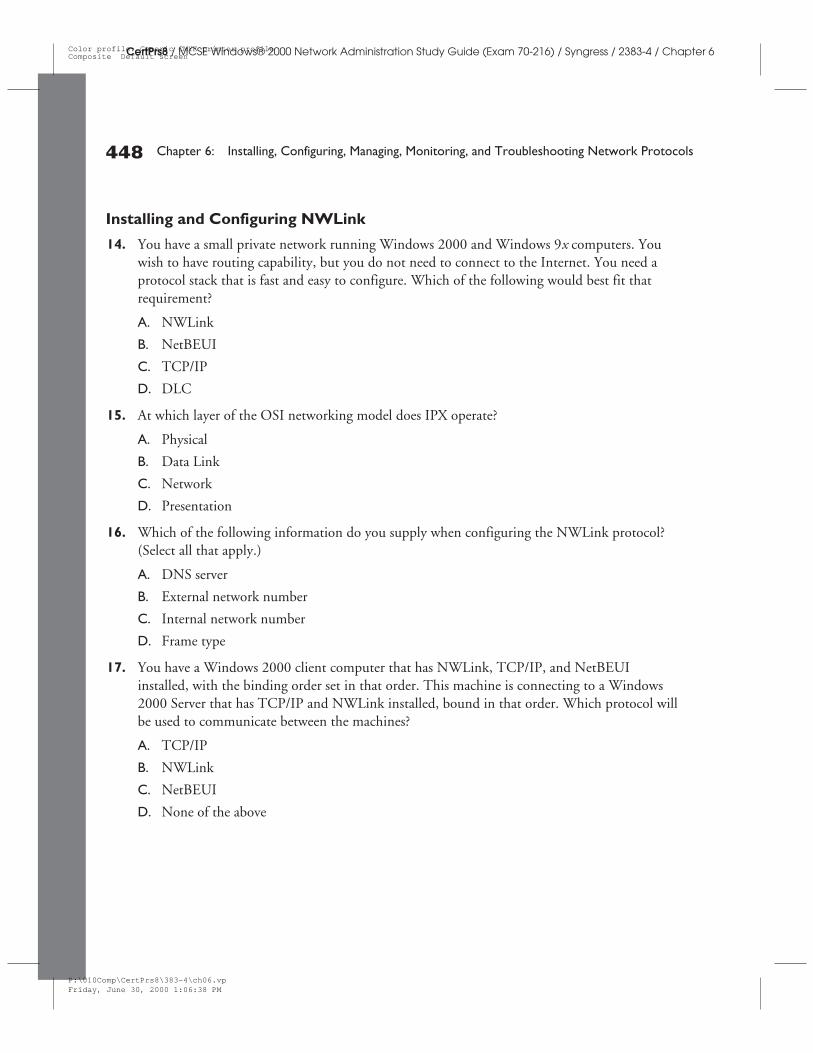
Installing and Configuring NWLink
14. You have a small private network running Windows 2000 and Windows 9x computers. Youwish to have routing capability, but you do not need to connect to the Internet. You need aprotocol stack that is fast and easy to configure. Which of the following would best fit thatrequirement?
A. NWLink
B. NetBEUI
C. TCP/IP
D. DLC
15. At which layer of the OSI networking model does IPX operate?
A. Physical
B. Data Link
C. Network
D. Presentation
16. Which of the following information do you supply when configuring the NWLink protocol?(Select all that apply.)
A. DNS server
B. External network number
C. Internal network number
D. Frame type
17. You have a Windows 2000 client computer that has NWLink, TCP/IP, and NetBEUIinstalled, with the binding order set in that order. This machine is connecting to a Windows2000 Server that has TCP/IP and NWLink installed, bound in that order. Which protocol willbe used to communicate between the machines?
A. TCP/IP
B. NWLink
C. NetBEUI
D. None of the above
448 Chapter 6: Installing, Configuring, Managing, Monitoring, and Troubleshooting Network Protocols
CertPrs8 / MCSE Windows® 2000 Network Administration Study Guide (Exam 70-216) / Syngress / 2383-4 / Chapter 6
P:\010Comp\CertPrs8\383-4\ch06.vpFriday, June 30, 2000 1:06:38 PM
Color profile: Generic CMYK printer profileComposite Default screen
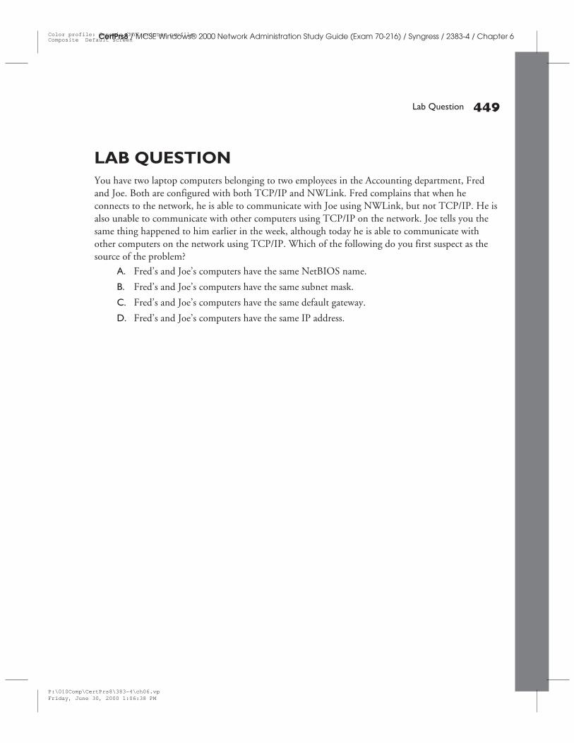
LAB QUESTIONYou have two laptop computers belonging to two employees in the Accounting department, Fredand Joe. Both are configured with both TCP/IP and NWLink. Fred complains that when heconnects to the network, he is able to communicate with Joe using NWLink, but not TCP/IP. He isalso unable to communicate with other computers using TCP/IP on the network. Joe tells you thesame thing happened to him earlier in the week, although today he is able to communicate withother computers on the network using TCP/IP. Which of the following do you first suspect as thesource of the problem?
A. Fred’s and Joe’s computers have the same NetBIOS name.
B. Fred’s and Joe’s computers have the same subnet mask.
C. Fred’s and Joe’s computers have the same default gateway.
D. Fred’s and Joe’s computers have the same IP address.
Lab Question 449
CertPrs8 / MCSE Windows® 2000 Network Administration Study Guide (Exam 70-216) / Syngress / 2383-4 / Chapter 6
P:\010Comp\CertPrs8\383-4\ch06.vpFriday, June 30, 2000 1:06:38 PM
Color profile: Generic CMYK printer profileComposite Default screen
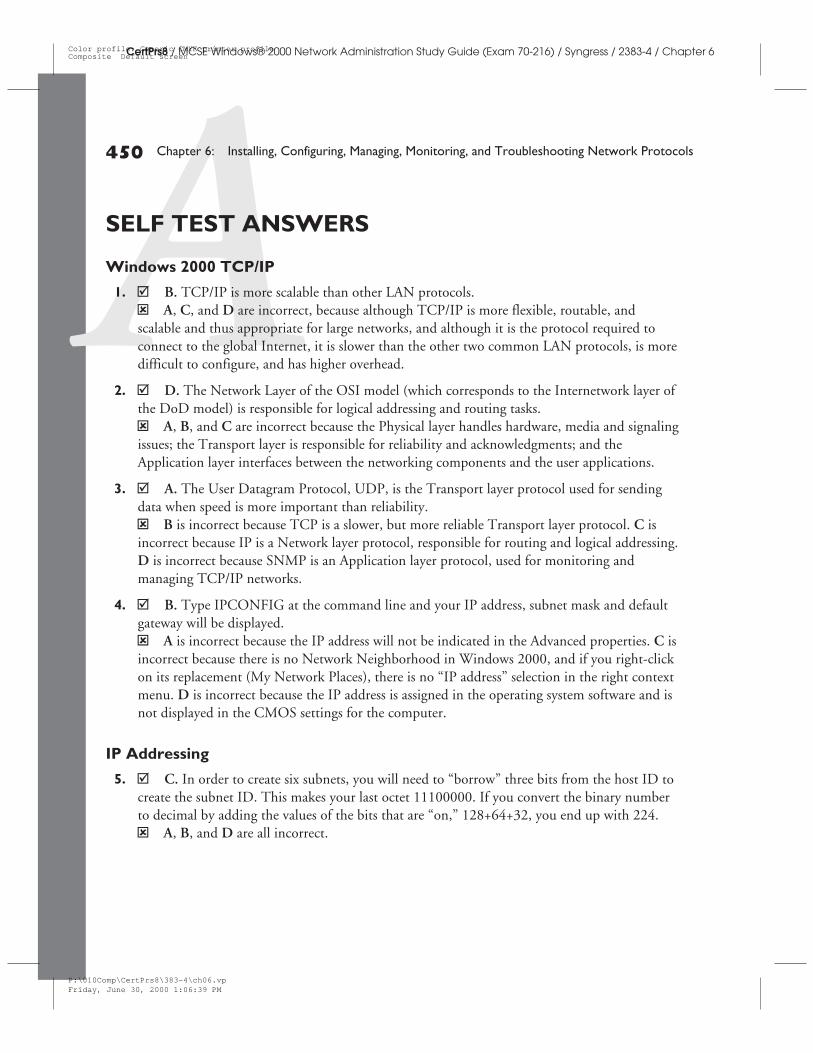
450 Chapter 6: Installing, Configuring, Managing, Monitoring, and Troubleshooting Network Protocols
CertPrs8 / MCSE Windows® 2000 Network Administration Study Guide (Exam 70-216) / Syngress / 2383-4 / Chapter 6
SELF TEST ANSWERS
Windows 2000 TCP/IP
1. þ B. TCP/IP is more scalable than other LAN protocols.ý A, C, and D are incorrect, because although TCP/IP is more flexible, routable, andscalable and thus appropriate for large networks, and although it is the protocol required toconnect to the global Internet, it is slower than the other two common LAN protocols, is moredifficult to configure, and has higher overhead.
2. þ D. The Network Layer of the OSI model (which corresponds to the Internetwork layer ofthe DoD model) is responsible for logical addressing and routing tasks.ý A, B, and C are incorrect because the Physical layer handles hardware, media and signalingissues; the Transport layer is responsible for reliability and acknowledgments; and theApplication layer interfaces between the networking components and the user applications.
3. þ A. The User Datagram Protocol, UDP, is the Transport layer protocol used for sendingdata when speed is more important than reliability.ý B is incorrect because TCP is a slower, but more reliable Transport layer protocol. C isincorrect because IP is a Network layer protocol, responsible for routing and logical addressing.D is incorrect because SNMP is an Application layer protocol, used for monitoring andmanaging TCP/IP networks.
4. þ B. Type IPCONFIG at the command line and your IP address, subnet mask and defaultgateway will be displayed.ý A is incorrect because the IP address will not be indicated in the Advanced properties. C isincorrect because there is no Network Neighborhood in Windows 2000, and if you right-clickon its replacement (My Network Places), there is no “IP address” selection in the right contextmenu. D is incorrect because the IP address is assigned in the operating system software and isnot displayed in the CMOS settings for the computer.
IP Addressing
5. þ C. In order to create six subnets, you will need to “borrow” three bits from the host ID tocreate the subnet ID. This makes your last octet 11100000. If you convert the binary numberto decimal by adding the values of the bits that are “on,” 128+64+32, you end up with 224.ý A, B, and D are all incorrect.
P:\010Comp\CertPrs8\383-4\ch06.vpFriday, June 30, 2000 1:06:39 PM
Color profile: Generic CMYK printer profileComposite Default screen
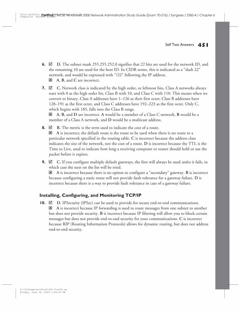
Self Test Answers 451
CertPrs8 / MCSE Windows® 2000 Network Administration Study Guide (Exam 70-216) / Syngress / 2383-4 / Chapter 6
6. þ D. The subnet mask 255.255.252.0 signifies that 22 bits are used for the network ID, andthe remaining 10 are used for the host ID. In CIDR terms, this is indicated as a “slash 22”network, and would be expressed with “/22” following the IP address.ý A, B, and C are incorrect.
7. þ C. Network class is indicated by the high order, or leftmost bits. Class A networks alwaysstart with 0 as the high order bit, Class B with 10, and Class C with 110. This means when weconvert to binary, Class A addresses have 1–126 as their first octet, Class B addresses have128–191 as the first octet, and Class C addresses have 192–223 as the first octet. Only C,which begins with 185, falls into the Class B range.ý A, B, and D are incorrect. A would be a member of a Class C network, B would be amember of a Class A network, and D would be a multicast address.
8. þ B. The metric is the term used to indicate the cost of a route.ý A is incorrect; the default route is the route to be used when there is no route to aparticular network specified in the routing table. C is incorrect because the address classindicates the size of the network, not the cost of a route. D is incorrect because the TTL is theTime to Live, used to indicate how long a receiving computer or router should hold or use thepacket before it expires.
9. þ C. If you configure multiple default gateways, the first will always be used unless it fails, inwhich case the next on the list will be tried.ý A is incorrect because there is no option to configure a “secondary” gateway. B is incorrectbecause configuring a static route will not provide fault tolerance for a gateway failure. D isincorrect because there is a way to provide fault tolerance in case of a gateway failure.
Installing, Configuring, and Monitoring TCP/IP
10. þ D. IPSecurity (IPSec) can be used to provide for secure end-to-end communications.ý A is incorrect because IP forwarding is used to route messages from one subnet to anotherbut does not provide security. B is incorrect because IP filtering will allow you to block certainmessages but does not provide end-to-end security for your communications. C is incorrectbecause RIP (Routing Information Protocols) allows for dynamic routing, but does not addressend-to-end security.
P:\010Comp\CertPrs8\383-4\ch06.vpFriday, June 30, 2000 1:06:39 PM
Color profile: Generic CMYK printer profileComposite Default screen
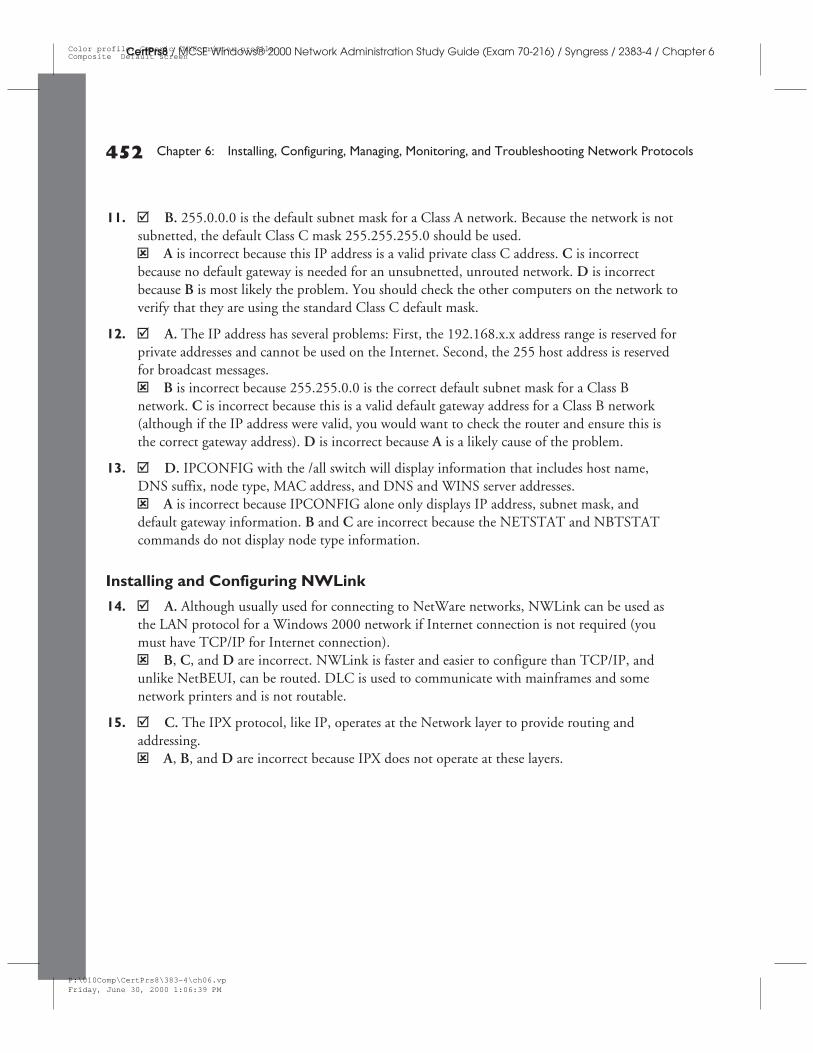
452 Chapter 6: Installing, Configuring, Managing, Monitoring, and Troubleshooting Network Protocols
CertPrs8 / MCSE Windows® 2000 Network Administration Study Guide (Exam 70-216) / Syngress / 2383-4 / Chapter 6
11. þ B. 255.0.0.0 is the default subnet mask for a Class A network. Because the network is notsubnetted, the default Class C mask 255.255.255.0 should be used.ý A is incorrect because this IP address is a valid private class C address. C is incorrectbecause no default gateway is needed for an unsubnetted, unrouted network. D is incorrectbecause B is most likely the problem. You should check the other computers on the network toverify that they are using the standard Class C default mask.
12. þ A. The IP address has several problems: First, the 192.168.x.x address range is reserved forprivate addresses and cannot be used on the Internet. Second, the 255 host address is reservedfor broadcast messages.ý B is incorrect because 255.255.0.0 is the correct default subnet mask for a Class Bnetwork. C is incorrect because this is a valid default gateway address for a Class B network(although if the IP address were valid, you would want to check the router and ensure this isthe correct gateway address). D is incorrect because A is a likely cause of the problem.
13. þ D. IPCONFIG with the /all switch will display information that includes host name,DNS suffix, node type, MAC address, and DNS and WINS server addresses.ý A is incorrect because IPCONFIG alone only displays IP address, subnet mask, anddefault gateway information. B and C are incorrect because the NETSTAT and NBTSTATcommands do not display node type information.
Installing and Configuring NWLink
14. þ A. Although usually used for connecting to NetWare networks, NWLink can be used asthe LAN protocol for a Windows 2000 network if Internet connection is not required (youmust have TCP/IP for Internet connection).ý B, C, and D are incorrect. NWLink is faster and easier to configure than TCP/IP, andunlike NetBEUI, can be routed. DLC is used to communicate with mainframes and somenetwork printers and is not routable.
15. þ C. The IPX protocol, like IP, operates at the Network layer to provide routing andaddressing.ý A, B, and D are incorrect because IPX does not operate at these layers.
P:\010Comp\CertPrs8\383-4\ch06.vpFriday, June 30, 2000 1:06:39 PM
Color profile: Generic CMYK printer profileComposite Default screen
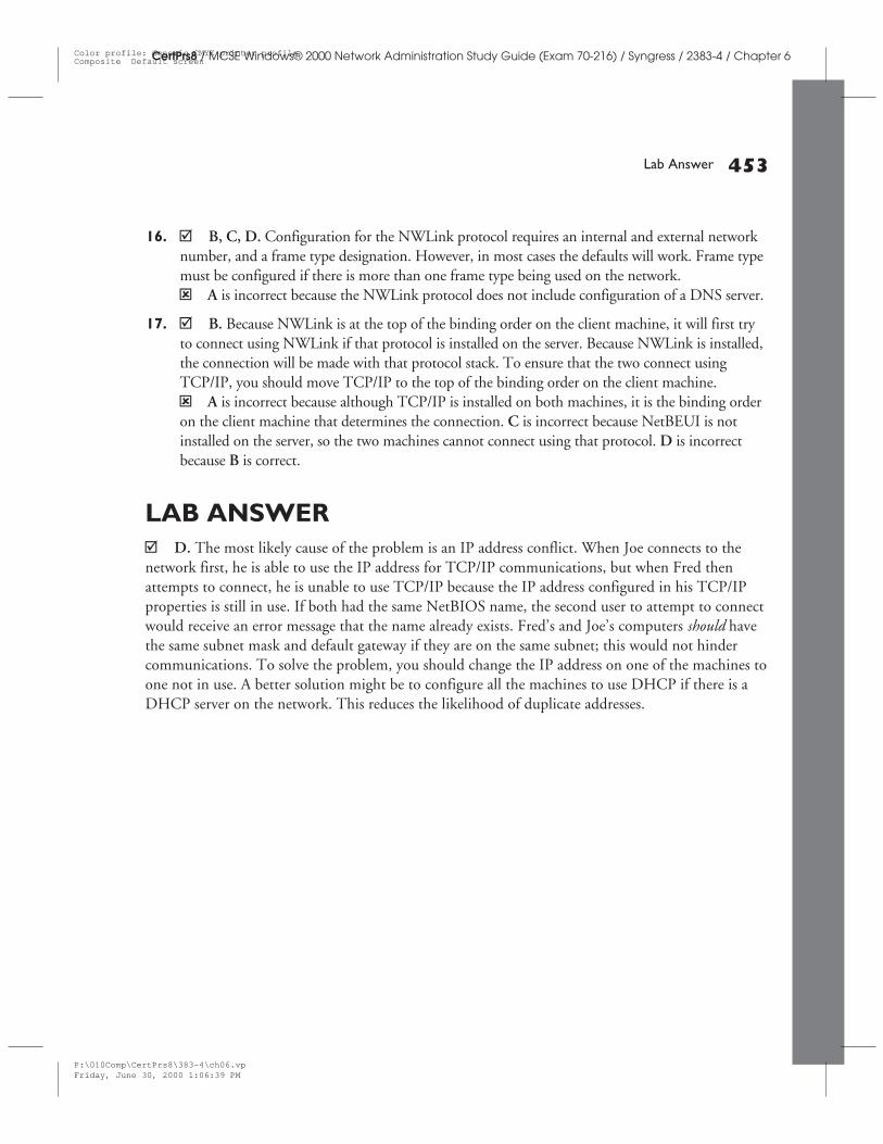
16. þ B, C, D. Configuration for the NWLink protocol requires an internal and external networknumber, and a frame type designation. However, in most cases the defaults will work. Frame typemust be configured if there is more than one frame type being used on the network.ý A is incorrect because the NWLink protocol does not include configuration of a DNS server.
17. þ B. Because NWLink is at the top of the binding order on the client machine, it will first tryto connect using NWLink if that protocol is installed on the server. Because NWLink is installed,the connection will be made with that protocol stack. To ensure that the two connect usingTCP/IP, you should move TCP/IP to the top of the binding order on the client machine.ý A is incorrect because although TCP/IP is installed on both machines, it is the binding orderon the client machine that determines the connection. C is incorrect because NetBEUI is notinstalled on the server, so the two machines cannot connect using that protocol. D is incorrectbecause B is correct.
LAB ANSWERþ D. The most likely cause of the problem is an IP address conflict. When Joe connects to thenetwork first, he is able to use the IP address for TCP/IP communications, but when Fred thenattempts to connect, he is unable to use TCP/IP because the IP address configured in his TCP/IPproperties is still in use. If both had the same NetBIOS name, the second user to attempt to connectwould receive an error message that the name already exists. Fred’s and Joe’s computers should havethe same subnet mask and default gateway if they are on the same subnet; this would not hindercommunications. To solve the problem, you should change the IP address on one of the machines toone not in use. A better solution might be to configure all the machines to use DHCP if there is aDHCP server on the network. This reduces the likelihood of duplicate addresses.
Lab Answer 453
CertPrs8 / MCSE Windows® 2000 Network Administration Study Guide (Exam 70-216) / Syngress / 2383-4 / Chapter 6
P:\010Comp\CertPrs8\383-4\ch06.vpFriday, June 30, 2000 1:06:39 PM
Color profile: Generic CMYK printer profileComposite Default screen

CertPrs8 / MCSE Windows® 2000 Network Administration Study Guide (Exam 70-216) / Syngress / 2383-4Blind Folio 454
P:\010Comp\CertPrs8\383-4\ch06.vpFriday, June 30, 2000 1:06:39 PM
Color profile: Generic CMYK printer profileComposite Default screen
![[1]Oracle® Fusion Middleware Installing and Configuring ... · Installing and Configuring Oracle Enterprise Data Quality 12c ... Oracle Fusion Middleware Installing and Configuring](https://img.dokumen.tips/doc/110x75/5b8396637f8b9a47588d872b/1oracle-fusion-middleware-installing-and-configuring-installing-and.jpg)