Embed Size (px)
Citation preview

1
1
1 | P a g e
Installation/Service &
Operators Manual
Model 13-FBT-4WFT-E2
4 Way Float Top X-Ray Table
Tingle X-Ray, LLC 5481 Skyland Boulevard East
Cottondale, Alabama 35453
Telephone (205) 556-3803
DO NOT INSTALL OR OPERATE THIS FLOAT TOP TABLE WITHOUT FIRST READING AND UNDERSTANDING THIS MANUAL.

1
1
2 | P a g e
TXR
Title: User/Assembler Manual
Model 13-FBT-4WFT-E2 Technical Publication 780.205.00
Revision Date Implemented Reason for
Change
Approved By
0 6-7-2007 New Edition Jerry Tingle
1 8-10-2009 Table Redesign Jerry Tingle
2 10-12-2009 Various Changes RD/BB/DH
3 6-10-2011 Table Top Redesign RD/BB/DH
4 1-20-2012 Revised Content B Barnhill
5 3-16-2013 Review &
Specification Revision
Dana Emakoji
Larry West
1
1
3 | P a g e
Table of Contents
DISCLAIMER........................................................................................................... 5
SECTION 1 PRE-INSTALLATION ......................................................................... 5
SECTION 2 INTRODUCTION................................................................................. 5
SECTION 3 SAFETY .............................................................................................. 6
SECTION 4 INSTALLATION .................................................................................. 7
SECTION 5 OPERATING PROCEDURES .......................................................... 15
SECTION 6 SPECIFICATIONS ............................................................................ 16
SECTION 7 ROUTINE MAINTENANCE .............................................................. 16
SECTION 8 SERVICE .......................................................................................... 16
SECTION 9 SCHEMATICS .................................................................................. 17

1
1
4 | P a g e
IMPORTANT! … X-Ray Protection
X-RAY EQUIPMENT IS DANGEROUS TO BOTH PATIENT AND OPERATOR UNLESS
MEASURES OF PROTECTION ARE STRICTLY OBSERVED
X-ray equipment if not properly used may cause injury. Accordingly, the instructions herein should be thoroughly read and understood before attempting to place this equipment in operation. We will be glad to assist and cooperate in placing this equipment in use. Although this apparatus is built to the highest safety standards and incorporates a high degree of protection against X-radiation other than the useful beam, no practical design of equipment can provide complete protection. No can any practical design compel the operator to take adequate precautions to prevent the possibility of any persons carelessly, unwisely, or unknowingly exposing themselves of others to X-radiation. It is important that everyone working with X-radiation be properly trained and take adequate steps to insure protection against injury. The manufacturer assumes that all operator and service personnel authorized to use, install, calibrate and maintain this equipment is cognizant of the danger of excessive exposure to X-radiation, is sufficiently trained and has the required knowledge for it. The equipment herin described is sold with the understanding that the manufacturer, its agents, and representatives are not liable for injury or damage which may result from exposure to X-radiation.Various protective material and devices are available. It is recommended that such materials and devices be used.
------------------------------------------------------------------------------------------------------------------------
!IMPORTANTE! …Proteccion ante los rayos-X
LOS EQUIPOS DE RAYOS-X SON PELIGROSOS PARA EL PACIENTE Y EL OPERADOR A MENOS QUE LAS MEDIDAS DE PROTECCION SEAN ESTRICTAMENTE OBSERVADAS
Si el equipo de rayos-X no se usa adecuadamente, puede causar lesions. Por este motive, las instrucciones aqui incluidas se deben leer y comprender en su totalidad antes de intentar poner el equipo en funcionamiento. Estaremos gustosos de asistir y cooperar en poner el equipo en marcha. Aunque el equipo esta construido segun las normas de seguridad mas estrictas y presenta un alto grado de proteccion contra las radiaciones-X, ningun diseno practico puede ofecer una proteccion complete. Tampoco ningun diseno practico puede obligor al operador a tomar las precauciones adecuadas para prevenir la posibilidad de que caulquier persona de manera descuidada, poco sensate o ignorante, se exponga a radiaciones directas o indirectas. Es importante que caulquier persona relacionada con radiaciones-X este debidamente entrenada y torne las medidas adecuadas para asegurar la proteccion contra posibles lesions. El fabricante assume que todo operador y personal de servicio authorizado para manejar, instalar, calibrar o mantener este equipo, es consciente del peligro que conlieva la exposicion excesiva a las radiaciones-X, esta suficientemente entrenado y posee los conocimiento necesarios para ello. Por lo tanto, el equipo aqui descrito se vende entendiendo que el fabricante, sus agents y representantes no tienen ninguna responsabilidad en case de lesions o danos que puedan resultar de las exposicion a dichas radiaciones. Existen diversos materials y dispositivos protectors, cuyo uso es recomendavie.

1
1
5 | P a g e
Section 1 Pre-Installation Prior to installation, perform any necessary floor preparations to guarantee the floor is structurally sound and level. Review the table specifications from page 15 of this manual and map out the position the table will be placed within the room. This method will ensure you are able to take full advantage of the full range of table top motion allowed.
Section 2 Introduction The 13-FBT-4WFT-E2 Float Top Table with Aluminum Extruded Rails has been designed for use in medical x-ray environments. This table provides cross and lateral movement of the table-top and lateral movement of a Grid Cabinet or Bucky. Magnetic locks are provided for cross and lateral table-top movement along with Bucky/Grid Cabinet movement. Each table has a name plate (Certification Label) which provides the serial number, date of manufacture and model identification number. This label is located on the back right-hand side of the table if you are facing the table. It is imperative you locate the certified label and have all the information available from that label when you contact your original installer for service or parts.
Notice: If unique situations or applications arise that are not covered in this manual, please call for assistance.
1
1
6 | P a g e
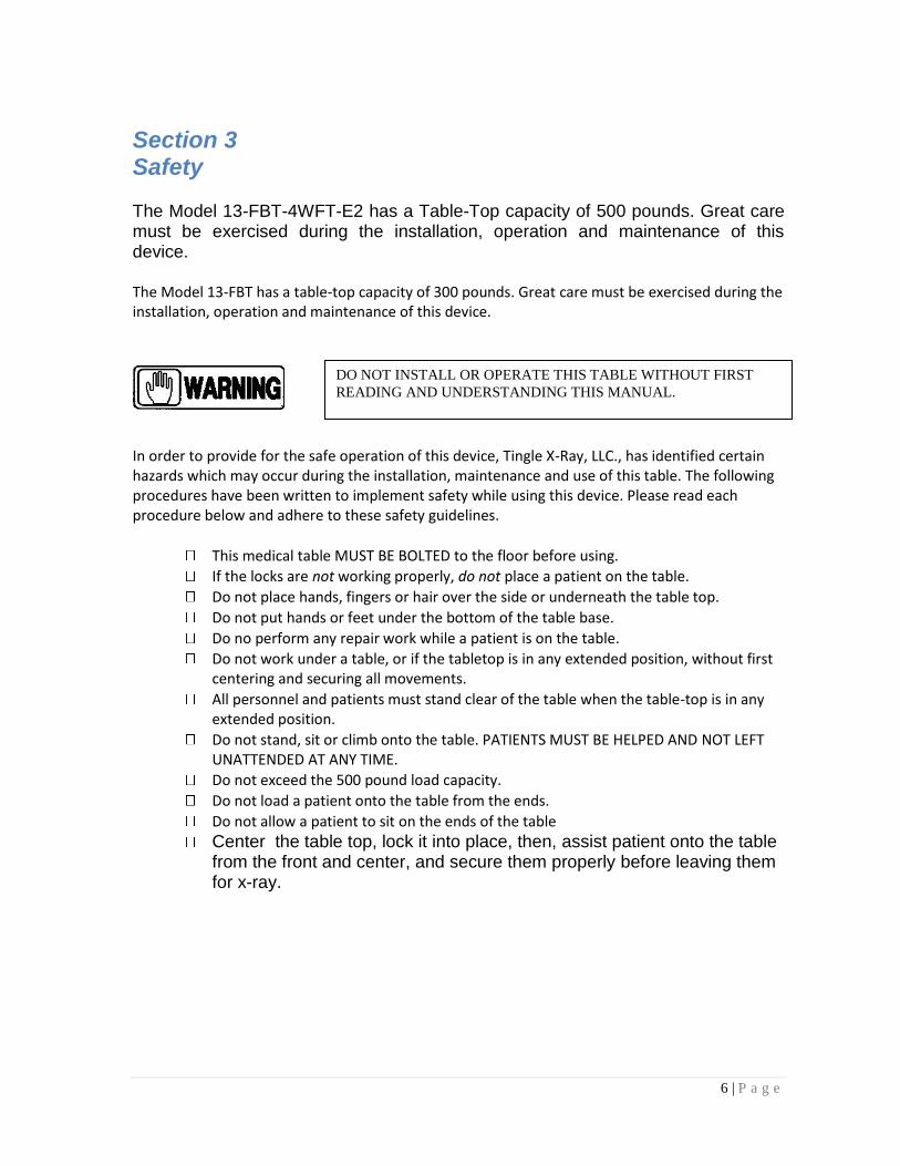
Section 3 Safety The Model 13-FBT-4WFT-E2 has a Table-Top capacity of 500 pounds. Great care must be exercised during the installation, operation and maintenance of this device. The Model 13-FBT has a table-top capacity of 300 pounds. Great care must be exercised during the installation, operation and maintenance of this device.
In order to provide for the safe operation of this device, Tingle X-Ray, LLC., has identified certain hazards which may occur during the installation, maintenance and use of this table. The following procedures have been written to implement safety while using this device. Please read each procedure below and adhere to these safety guidelines.
This medical table MUST BE BOLTED to the floor before using.
If the locks are not working properly, do not place a patient on the table.
Do not place hands, fingers or hair over the side or underneath the table top.
Do not put hands or feet under the bottom of the table base.
Do no perform any repair work while a patient is on the table.
Do not work under a table, or if the tabletop is in any extended position, without first centering and securing all movements.
All personnel and patients must stand clear of the table when the table-top is in any extended position.
Do not stand, sit or climb onto the table. PATIENTS MUST BE HELPED AND NOT LEFT UNATTENDED AT ANY TIME.
Do not exceed the 500 pound load capacity.
Do not load a patient onto the table from the ends.
Do not allow a patient to sit on the ends of the table
Center the table top, lock it into place, then, assist patient onto the table from the front and center, and secure them properly before leaving them for x-ray.
DO NOT INSTALL OR OPERATE THIS TABLE WITHOUT FIRST
READING AND UNDERSTANDING THIS MANUAL.
1
1
7 | P a g e
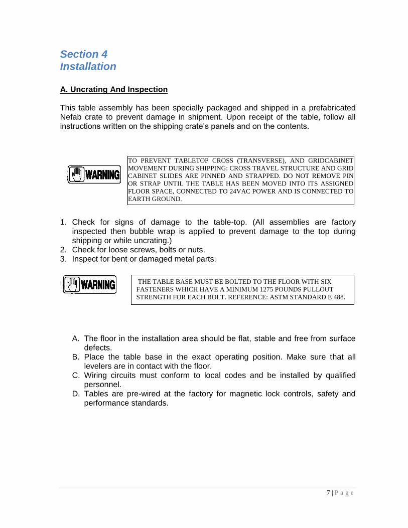
Section 4 Installation A. Uncrating And Inspection This table assembly has been specially packaged and shipped in a prefabricated Nefab crate to prevent damage in shipment. Upon receipt of the table, follow all instructions written on the shipping crate’s panels and on the contents.
1. Check for signs of damage to the table-top. (All assemblies are factory
inspected then bubble wrap is applied to prevent damage to the top during shipping or while uncrating.)
2. Check for loose screws, bolts or nuts. 3. Inspect for bent or damaged metal parts.
A. The floor in the installation area should be flat, stable and free from surface defects.
B. Place the table base in the exact operating position. Make sure that all levelers are in contact with the floor.
C. Wiring circuits must conform to local codes and be installed by qualified personnel.
D. Tables are pre-wired at the factory for magnetic lock controls, safety and performance standards.
TO PREVENT TABLETOP CROSS (TRANSVERSE), AND GRIDCABINET
MOVEMENT DURING SHIPPING: CROSS TRAVEL STRUCTURE AND GRID
CABINET SLIDES ARE PINNED AND STRAPPED. DO NOT REMOVE PIN
OR STRAP UNTIL THE TABLE HAS BEEN MOVED INTO ITS ASSIGNED
FLOOR SPACE, CONNECTED TO 24VAC POWER AND IS CONNECTED TO
EARTH GROUND.
THE TABLE BASE MUST BE BOLTED TO THE FLOOR WITH SIX
FASTENERS WHICH HAVE A MINIMUM 1275 POUNDS PULLOUT
STRENGTH FOR EACH BOLT. REFERENCE: ASTM STANDARD E 488.

1
1
8 | P a g e
B. Table Top Preparation
The Table Top, when shipped, is locked down by two shipping brackets. These brackets must be removed prior to operation. The table top panel is attached to the Table Frame by Velcro. Carefully separate the hooks and loops of the Velcro down the long side of one side of the table, then, slowly lift the panel top up and away from the Table Frame.
Next, remove and discard the two shipping brackets shown here in the photo.
Shipping Bracket
Shipping Bracket

1
1
9 | P a g e
Remove foam blocks to free the bucky/cabinet movement as shown.
After the brackets and foam blocks have been removed, check for full motion of table frame and receptor cabinet. If both are moving smoothly with no binding, replace the table top. C. Leveling Depending on the floor conditions, it may be necessary to level the table to the floor. The table is provided with four leveling feet for this purpose. Using a wrench, the levelers may be adjusted accordingly. (See Photo). Levelers are shipped in the fully retracted position.
Foam Block
Foam Block

1
1
10 | P a g e
The base must be anchored to the floor. Minimum requirements (4) fasteners with a 1275 pound pullout strength for each bolt. (4) Anchoring Plates have been provided for this purpose. See Photo. (Reference: ASTM Standard E 488.)
D. Power Supply The Power Supply Board is located inside the table base under a cover.(See Photos).

1
1
11 | P a g e
The Power Supply Board supplies all three lock assemblies and requires 24 VAC Input. The circuit is protected by a 3 amp fuse. If replacement is necessary, replace with only an equivalent fuse.
24 VAC Input
24 VDC to Locks
Foot Switch Cable
DO NOT ATTEMPT TO MODIFY OR CHANGE THE ELECTRICAL CIRCUIT. ANY ALTERATIONS WILL CAUSE DAMAGE TO THE POWER SUPPLY AND POSSIBLE PHYSICAL INJURY. ONLY AUTHORIZED QUALIFIED PERSONNEL SHOULD SERVICE THE ELECTRICAL CIRCUITS.
1
1
12 | P a g e
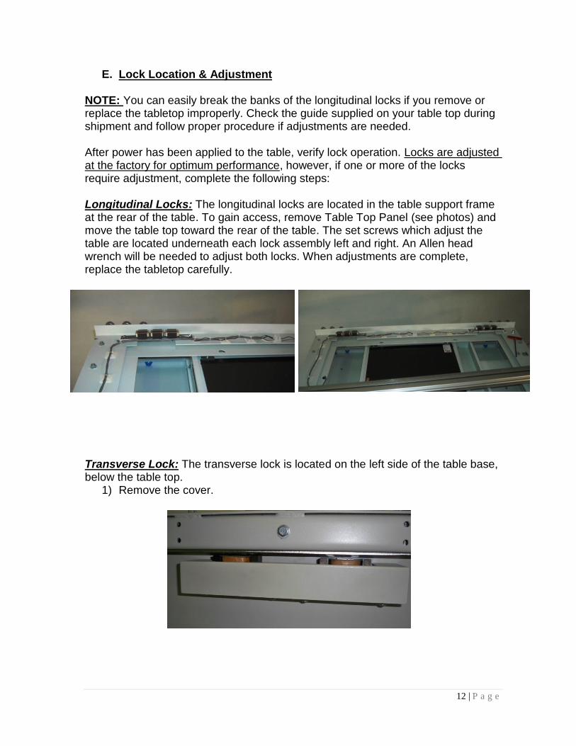
E. Lock Location & Adjustment NOTE: You can easily break the banks of the longitudinal locks if you remove or replace the tabletop improperly. Check the guide supplied on your table top during shipment and follow proper procedure if adjustments are needed. After power has been applied to the table, verify lock operation. Locks are adjusted at the factory for optimum performance, however, if one or more of the locks require adjustment, complete the following steps: Longitudinal Locks: The longitudinal locks are located in the table support frame at the rear of the table. To gain access, remove Table Top Panel (see photos) and move the table top toward the rear of the table. The set screws which adjust the table are located underneath each lock assembly left and right. An Allen head wrench will be needed to adjust both locks. When adjustments are complete, replace the tabletop carefully.
Transverse Lock: The transverse lock is located on the left side of the table base, below the table top.
1) Remove the cover.

1
1
13 | P a g e
All locks on the table adjust in a similar fashion. Each magnetic lock can be raised or lowered by loosening the hex nut then turning the adjusting screw in or out for the appropriate height. The distance between the magnetic lock and the strip it is adhering to should only be a hairline distance. When power is placed on the lock, the flex plate on the magnetic lock will close the gap and stop movement of the area in which the lock is placed. After all adjustments have been made retighten each hex nut to secure the lock in the proper position. (See Photo).
Replace the covers.
Locknut
Adjusting Nut

1
1
14 | P a g e
Bucky or Grid Cabinet Lock: The bucky or grid cabinet lock is located underneath the table top and mounted directly to the middle left-hand side of the cabinet. The lock can be adjusted to the lock plate using the screws located on the top of the lock box, as shown.
Rear Base Cover
Receptor Lock
1
1
15 | P a g e
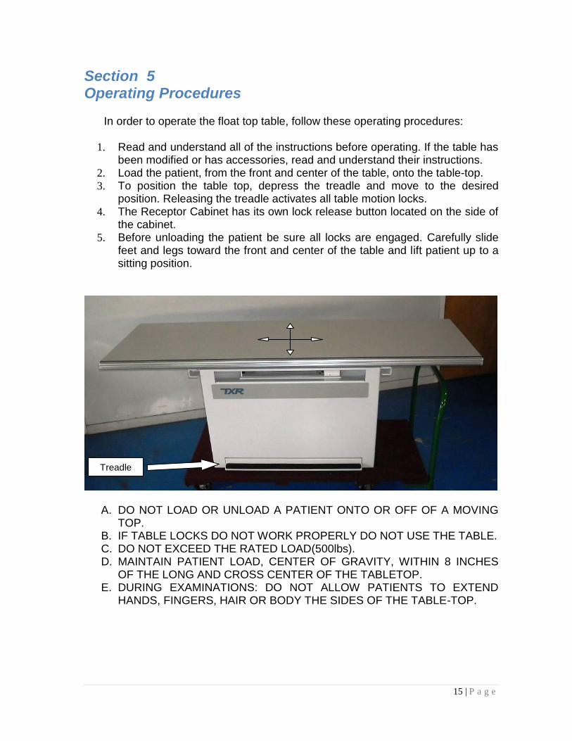
Section 5 Operating Procedures
In order to operate the float top table, follow these operating procedures:
1. Read and understand all of the instructions before operating. If the table has been modified or has accessories, read and understand their instructions.
2. Load the patient, from the front and center of the table, onto the table-top. 3. To position the table top, depress the treadle and move to the desired
position. Releasing the treadle activates all table motion locks. 4. The Receptor Cabinet has its own lock release button located on the side of
the cabinet. 5. Before unloading the patient be sure all locks are engaged. Carefully slide
feet and legs toward the front and center of the table and lift patient up to a sitting position.
A. DO NOT LOAD OR UNLOAD A PATIENT ONTO OR OFF OF A MOVING TOP.
B. IF TABLE LOCKS DO NOT WORK PROPERLY DO NOT USE THE TABLE. C. DO NOT EXCEED THE RATED LOAD(500lbs). D. MAINTAIN PATIENT LOAD, CENTER OF GRAVITY, WITHIN 8 INCHES
OF THE LONG AND CROSS CENTER OF THE TABLETOP. E. DURING EXAMINATIONS: DO NOT ALLOW PATIENTS TO EXTEND
HANDS, FINGERS, HAIR OR BODY THE SIDES OF THE TABLE-TOP.
Treadle
1
1
16 | P a g e
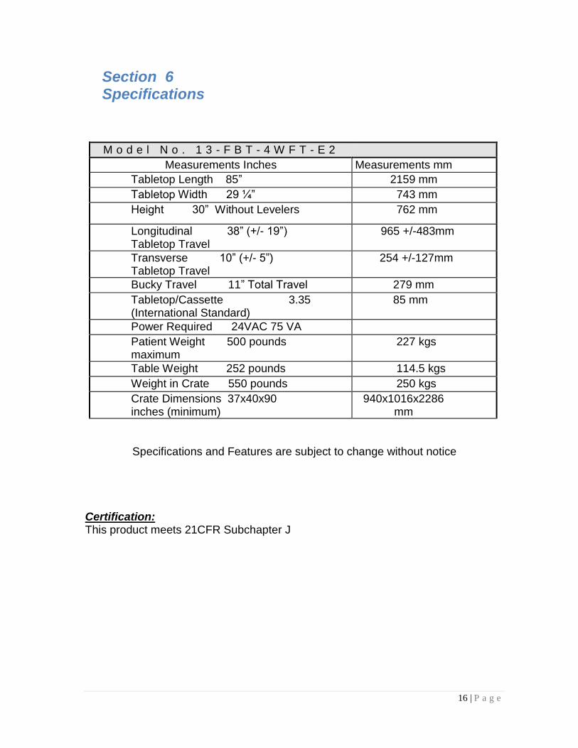
Section 6 Specifications
M o d e l N o . 1 3 - F B T - 4 W F T - E 2
Measurements Inches Measurements mm
Tabletop Length 85” 2159 mm
Tabletop Width 29 ¼” 743 mm
Height 30” Without Levelers 762 mm
Longitudinal 38” (+/- 19”) Tabletop Travel
965 +/-483mm
Transverse 10” (+/- 5”) Tabletop Travel
254 +/-127mm
Bucky Travel 11” Total Travel 279 mm
Tabletop/Cassette 3.35 (International Standard)
85 mm
Power Required 24VAC 75 VA
Patient Weight 500 pounds maximum
227 kgs
Table Weight 252 pounds 114.5 kgs
Weight in Crate 550 pounds 250 kgs
Crate Dimensions 37x40x90 inches (minimum)
940x1016x2286 mm
Specifications and Features are subject to change without notice Certification: This product meets 21CFR Subchapter J

1
1
17 | P a g e
Section 7 Routine Maintenance
All routine maintenance should be performed on a yearly basis. Before performing any maintenance, shut the power off. Center the table-top over the base and secure. Perform the routine listed checks. 1. Inspect all bearings for signs of wear. Replace if damaged. 2. Inspect wiring for damage or wear. Replace damaged wire immediately. 2. Check all table base fasteners. 3. Inspect table top for any physical damage.
Section 8 Service
There are no user serviceable components/parts on this table. If service is required, it should only be performed by qualified service personnel.
Section 9 Schematic