Embed Size (px)
Citation preview
Installation ManualSUNNY BOY 240SUNNY MULTIGATE
SMA-SB240-IA-en-12 | Version 1.2 AMERICAN ENGLISH
Legal ProvisionsThe information contained in these documents is property of SMA Solar Technology AG. Anypublication, whether in whole or in part, requires prior written approval by SMA Solar TechnologyAG. Internal reproduction used solely for the purpose of product evaluation or other proper use isallowed and does not require prior approval.
SMA WarrantyYou can download the current warranty conditions from the Internet at www.SMA-Solar.com.
TrademarksAll trademarks are recognized, even if not explicitly identified as such. A lack of identification doesnot mean that a product or symbol is not trademarked.The BLUETOOTH® word mark and logos are registered trademarks of Bluetooth SIG, Inc. and anyuse of these marks by SMA Solar Technology AG is under license.Modbus® is a registered trademark of Schneider Electric and is licensed by the ModbusOrganization, Inc.QR Code is a registered trademark of DENSO WAVE INCORPORATED.Phillips® and Pozidriv® are registered trademarks of Phillips Screw Company.Torx® is a registered trademark of Acument Global Technologies, Inc.
SMA Solar Technology AGSonnenallee 134266 NiestetalGermanyTel. +49 561 9522-0Fax +49 561 9522-100www.SMA.deE-mail: [email protected]© 2004 to 2014 SMA Solar Technology AG. All rights reserved.
Legal Provisions SMA Solar Technology AG
Installation ManualSMA-SB240-IA-en-122
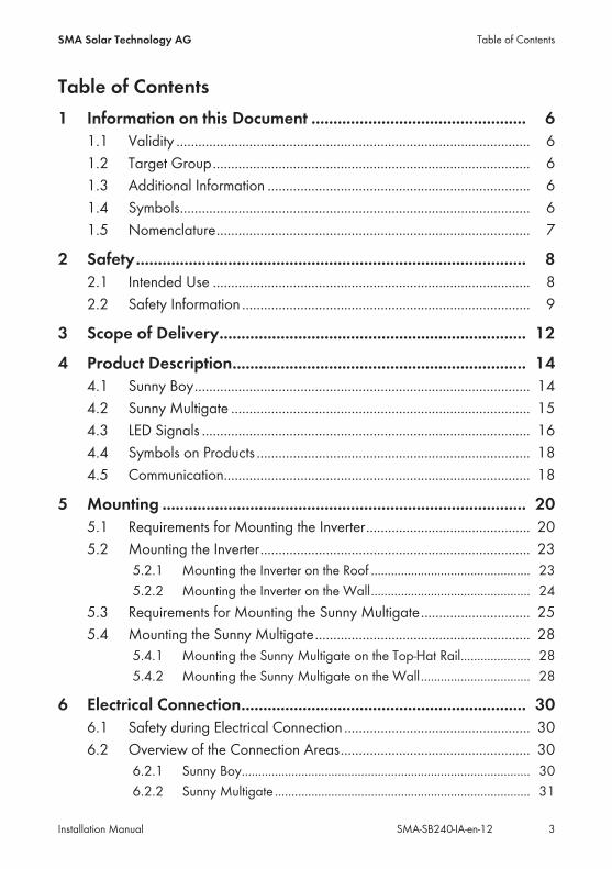
Table of Contents1 Information on this Document ................................................. 61.1 Validity ................................................................................................. 61.2 Target Group....................................................................................... 61.3 Additional Information ........................................................................ 61.4 Symbols................................................................................................ 61.5 Nomenclature...................................................................................... 7
2 Safety......................................................................................... 82.1 Intended Use ....................................................................................... 82.2 Safety Information ............................................................................... 9
3 Scope of Delivery...................................................................... 12
4 Product Description................................................................... 144.1 Sunny Boy............................................................................................ 144.2 Sunny Multigate .................................................................................. 154.3 LED Signals .......................................................................................... 164.4 Symbols on Products ........................................................................... 184.5 Communication.................................................................................... 18
5 Mounting ................................................................................... 205.1 Requirements for Mounting the Inverter............................................. 205.2 Mounting the Inverter.......................................................................... 23
5.2.1 Mounting the Inverter on the Roof ................................................ 235.2.2 Mounting the Inverter on the Wall................................................ 24
5.3 Requirements for Mounting the Sunny Multigate.............................. 255.4 Mounting the Sunny Multigate........................................................... 28
5.4.1 Mounting the Sunny Multigate on the Top-Hat Rail..................... 285.4.2 Mounting the Sunny Multigate on the Wall................................. 28
6 Electrical Connection................................................................. 306.1 Safety during Electrical Connection ................................................... 306.2 Overview of the Connection Areas.................................................... 30
6.2.1 Sunny Boy....................................................................................... 306.2.2 Sunny Multigate ............................................................................. 31
Table of ContentsSMA Solar Technology AG
Installation Manual 3SMA-SB240-IA-en-12
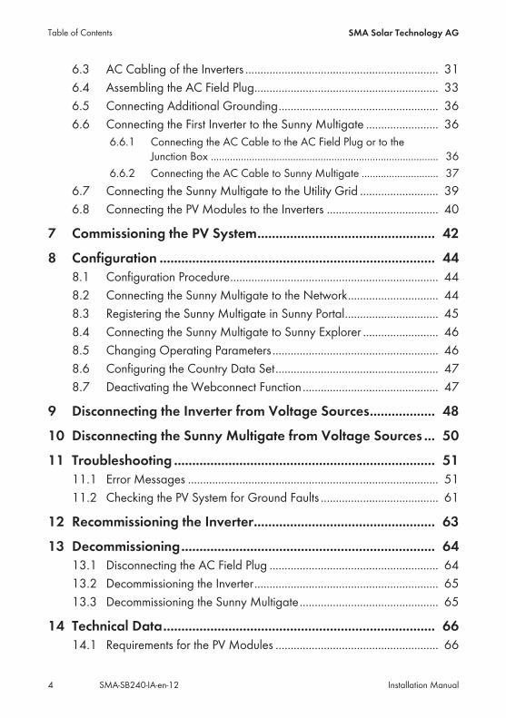
6.3 AC Cabling of the Inverters ................................................................ 316.4 Assembling the AC Field Plug............................................................. 336.5 Connecting Additional Grounding..................................................... 366.6 Connecting the First Inverter to the Sunny Multigate ........................ 36
6.6.1 Connecting the AC Cable to the AC Field Plug or to theJunction Box ................................................................................... 36
6.6.2 Connecting the AC Cable to Sunny Multigate ............................ 376.7 Connecting the Sunny Multigate to the Utility Grid .......................... 396.8 Connecting the PV Modules to the Inverters ..................................... 40
7 Commissioning the PV System................................................. 42
8 Configuration ............................................................................ 448.1 Configuration Procedure..................................................................... 448.2 Connecting the Sunny Multigate to the Network.............................. 448.3 Registering the Sunny Multigate in Sunny Portal............................... 458.4 Connecting the Sunny Multigate to Sunny Explorer ......................... 468.5 Changing Operating Parameters ....................................................... 468.6 Configuring the Country Data Set...................................................... 478.7 Deactivating the Webconnect Function............................................. 47
9 Disconnecting the Inverter from Voltage Sources.................. 48
10 Disconnecting the Sunny Multigate from Voltage Sources ... 50
11 Troubleshooting ........................................................................ 5111.1 Error Messages ................................................................................... 5111.2 Checking the PV System for Ground Faults ....................................... 61
12 Recommissioning the Inverter.................................................. 63
13 Decommissioning...................................................................... 6413.1 Disconnecting the AC Field Plug ........................................................ 6413.2 Decommissioning the Inverter............................................................. 6513.3 Decommissioning the Sunny Multigate.............................................. 65
14 Technical Data........................................................................... 6614.1 Requirements for the PV Modules ...................................................... 66
Table of Contents SMA Solar Technology AG
Installation ManualSMA-SB240-IA-en-124
14.2 Sunny Boy 240 ................................................................................... 6614.3 Sunny Multigate .................................................................................. 6914.4 Torques of AC Field Plugs................................................................... 71
15 Spare Parts and Accessories.................................................... 72
16 Contact....................................................................................... 74
17 EC Declaration of Conformity .................................................. 77
Table of ContentsSMA Solar Technology AG
Installation Manual 5SMA-SB240-IA-en-12
1 Information on this Document
1.1 ValidityThis document is valid for the following device types:• SB 240-10 (Sunny Boy 240)• Multigate-10 (Sunny Multigate)
1.2 Target GroupThe tasks described in this document must only be performed by qualified persons. Qualifiedpersons must have the following skills:• Knowledge of how an inverter works and is operated• Training in how to deal with the dangers and risks associated with installing and usingelectrical devices and installations
• Training in the installation and commissioning of electrical devices and installations• Knowledge of the applicable standards and directives• Knowledge of and compliance with this document and all safety precautions
1.3 Additional InformationLinks to additional information can be found at www.SMA-Solar.com:
Document title Document type"Micro Inverters in Sunny Portal"Monitoring and Visualization of Micro Inverters in Sunny Portal
User Manual
"Sunny Explorer"Software for Visualizing and Administrating a Speedwire System
User Manual
"Circuit Breaker"Dimensioning and Selection of a Suitable AC Circuit Breaker for In-verters under PV-Specific Influences
Technical Information
"Criteria for Selecting a Residual-Current Device" Technical Information
"Order Form for the SMA Grid Guard Code" Certificate
1.4 SymbolsSymbol Explanation
Indicates a hazardous situation which, if notavoided, will result in death or serious injury
Indicates a hazardous situation which, if notavoided, can result in death or serious injury
1 Information on this Document SMA Solar Technology AG
Installation ManualSMA-SB240-IA-en-126
Symbol ExplanationIndicates a hazardous situation which, if notavoided, can result in minor or moderate injury
Indicates a situation which, if not avoided, canresult in property damage
Information that is important for a specific topicor goal, but is not safety-relevant
Indicates a requirement for meeting a specificgoal
Desired result
A problem that might occur
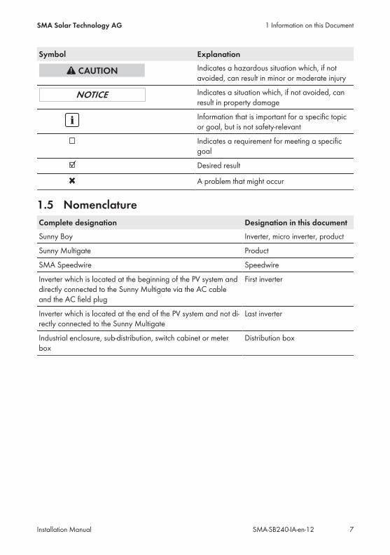
1.5 NomenclatureComplete designation Designation in this documentSunny Boy Inverter, micro inverter, product
Sunny Multigate Product
SMA Speedwire Speedwire
Inverter which is located at the beginning of the PV system anddirectly connected to the Sunny Multigate via the AC cableand the AC field plug
First inverter
Inverter which is located at the end of the PV system and not di-rectly connected to the Sunny Multigate
Last inverter
Industrial enclosure, sub-distribution, switch cabinet or meterbox
Distribution box
1 Information on this DocumentSMA Solar Technology AG
Installation Manual 7SMA-SB240-IA-en-12
2 Safety
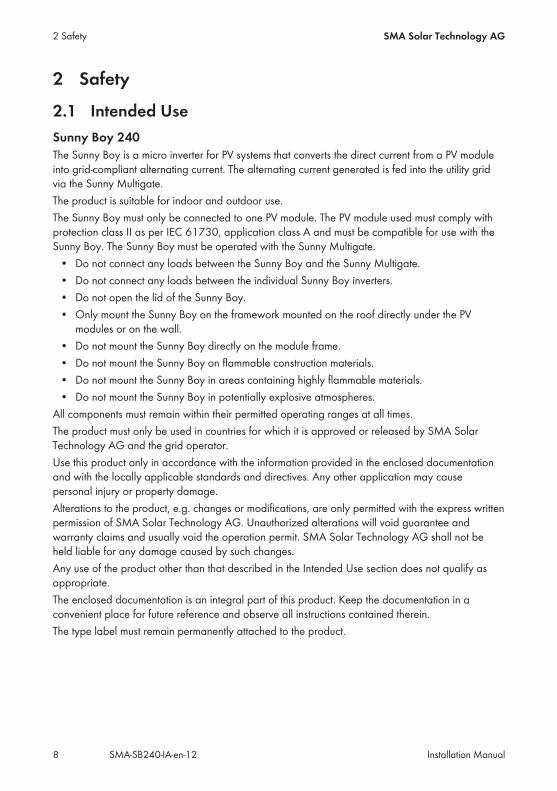
2.1 Intended UseSunny Boy 240The Sunny Boy is a micro inverter for PV systems that converts the direct current from a PV moduleinto grid-compliant alternating current. The alternating current generated is fed into the utility gridvia the Sunny Multigate.The product is suitable for indoor and outdoor use.The Sunny Boy must only be connected to one PV module. The PV module used must comply withprotection class II as per IEC 61730, application class A and must be compatible for use with theSunny Boy. The Sunny Boy must be operated with the Sunny Multigate.• Do not connect any loads between the Sunny Boy and the Sunny Multigate.• Do not connect any loads between the individual Sunny Boy inverters.• Do not open the lid of the Sunny Boy.• Only mount the Sunny Boy on the framework mounted on the roof directly under the PVmodules or on the wall.
• Do not mount the Sunny Boy directly on the module frame.• Do not mount the Sunny Boy on flammable construction materials.• Do not mount the Sunny Boy in areas containing highly flammable materials.• Do not mount the Sunny Boy in potentially explosive atmospheres.All components must remain within their permitted operating ranges at all times.The product must only be used in countries for which it is approved or released by SMA SolarTechnology AG and the grid operator.Use this product only in accordance with the information provided in the enclosed documentationand with the locally applicable standards and directives. Any other application may causepersonal injury or property damage.Alterations to the product, e.g. changes or modifications, are only permitted with the express writtenpermission of SMA Solar Technology AG. Unauthorized alterations will void guarantee andwarranty claims and usually void the operation permit. SMA Solar Technology AG shall not beheld liable for any damage caused by such changes.Any use of the product other than that described in the Intended Use section does not qualify asappropriate.The enclosed documentation is an integral part of this product. Keep the documentation in aconvenient place for future reference and observe all instructions contained therein.The type label must remain permanently attached to the product.
2 Safety SMA Solar Technology AG
Installation ManualSMA-SB240-IA-en-128
Sunny MultigateThe Sunny Multigate is a communication unit and forms the electrical connection point of the PVsystem with a maximum of twelve micro inverters to the utility grid. The Sunny Multigate is equippedwith an integrated disconnection point for grid monitoring. The Sunny Multigate is connectedbetween the micro inverters and the utility grid to feed the alternating current of the micro inverterscollectively into the utility grid.The product is designed for indoor use only.The Sunny Multigate must be installed and operated in a distribution box.• A maximum of twelve micro inverters can be connected to the Sunny Multigate.• No loads must be connected between the Sunny Boy and the Sunny Multigate.• No loads must be connected between the Sunny Multigate and the circuit breaker.• The grounding conductor of the AC cable from the inverter must be connected to the SunnyMultigate.
• The grounding conductor of the Sunny Multigate must be connected to the equipotentialbonding of the AC distribution board.
• The Sunny Multigate must not be opened.All components must remain within their permitted operating ranges at all times.The product must only be used in countries for which it is approved or released by SMA SolarTechnology AG and the grid operator.Use this product only in accordance with the information provided in the enclosed documentationand with the locally applicable standards and directives. Any other application may causepersonal injury or property damage.Alterations to the product, e.g. changes or modifications, are only permitted with the express writtenpermission of SMA Solar Technology AG. Unauthorized alterations will void guarantee andwarranty claims and usually void the operation permit. SMA Solar Technology AG shall not beheld liable for any damage caused by such changes.Any use of the product other than that described in the Intended Use section does not qualify asappropriate.The enclosed documentation is an integral part of this product. Keep the documentation in aconvenient place for future reference and observe all instructions contained therein.The type label must remain permanently attached to the product.
2.2 Safety InformationThis section contains safety information that must be observed at all times when working on or withthe product.To prevent personal injury and property damage and to ensure long-term operation of the product,read this section carefully and observe all safety information at all times.
2 SafetySMA Solar Technology AG
Installation Manual 9SMA-SB240-IA-en-12
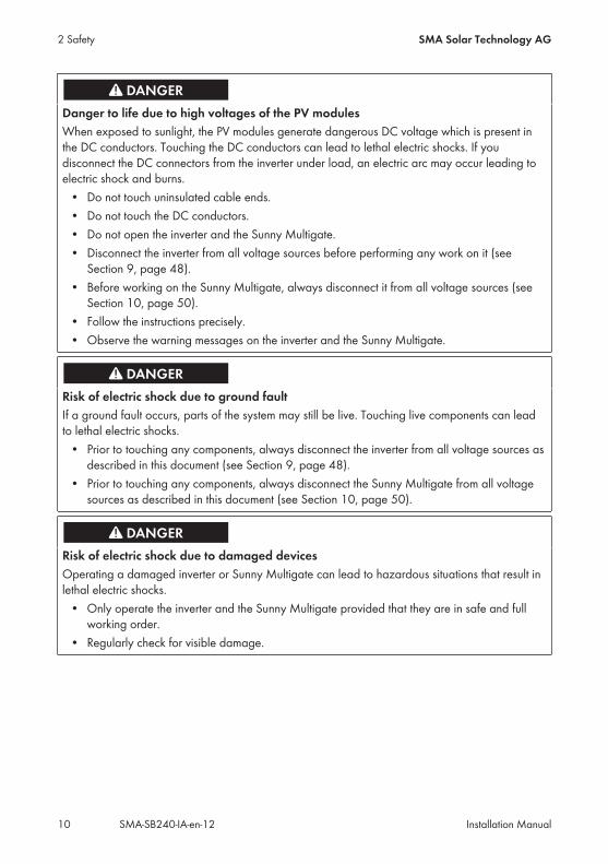
Danger to life due to high voltages of the PV modulesWhen exposed to sunlight, the PV modules generate dangerous DC voltage which is present inthe DC conductors. Touching the DC conductors can lead to lethal electric shocks. If youdisconnect the DC connectors from the inverter under load, an electric arc may occur leading toelectric shock and burns.• Do not touch uninsulated cable ends.• Do not touch the DC conductors.• Do not open the inverter and the Sunny Multigate.• Disconnect the inverter from all voltage sources before performing any work on it (seeSection 9, page 48).
• Before working on the Sunny Multigate, always disconnect it from all voltage sources (seeSection 10, page 50).
• Follow the instructions precisely.• Observe the warning messages on the inverter and the Sunny Multigate.
Risk of electric shock due to ground faultIf a ground fault occurs, parts of the system may still be live. Touching live components can leadto lethal electric shocks.• Prior to touching any components, always disconnect the inverter from all voltage sources asdescribed in this document (see Section 9, page 48).
• Prior to touching any components, always disconnect the Sunny Multigate from all voltagesources as described in this document (see Section 10, page 50).
Risk of electric shock due to damaged devicesOperating a damaged inverter or Sunny Multigate can lead to hazardous situations that result inlethal electric shocks.• Only operate the inverter and the Sunny Multigate provided that they are in safe and fullworking order.
• Regularly check for visible damage.
2 Safety SMA Solar Technology AG
Installation ManualSMA-SB240-IA-en-1210
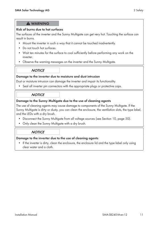
Risk of burns due to hot surfacesThe surfaces of the inverter and the Sunny Multigate can get very hot. Touching the surface canresult in burns.• Mount the inverter in such a way that it cannot be touched inadvertently.• Do not touch hot surfaces.• Wait ten minutes for the surface to cool sufficiently before performing any work on theinverter.
• Observe the warning messages on the inverter and the Sunny Multigate.
Damage to the inverter due to moisture and dust intrusionDust or moisture intrusion can damage the inverter and impair its functionality.• Seal all inverter pin connectors with the appropriate plugs or protective caps.
Damage to the Sunny Multigate due to the use of cleaning agentsThe use of cleaning agents may cause damage to components of the Sunny Multigate. If theSunny Multigate is dirty or dusty, you can clean the enclosure, the ventilation slots, the type label,and the LEDs with a dry brush.• Disconnect the Sunny Multigate from all voltage sources (see Section 10, page 50).• Only clean the Sunny Multigate with a dry brush.
Damage to the inverter due to the use of cleaning agents• If the inverter is dirty, clean the enclosure, the enclosure lid and the type label only usingclear water and a cloth.
2 SafetySMA Solar Technology AG
Installation Manual 11SMA-SB240-IA-en-12
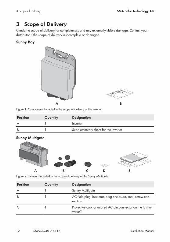
3 Scope of DeliveryCheck the scope of delivery for completeness and any externally visible damage. Contact yourdistributor if the scope of delivery is incomplete or damaged.
Sunny Boy
Figure 1: Components included in the scope of delivery of the inverter
Position Quantity DesignationA 1 Inverter
B 1 Supplementary sheet for the inverter
Sunny Multigate
Figure 2: Elements included in the scope of delivery of the Sunny Multigate
Position Quantity DesignationA 1 Sunny Multigate
B 1 AC field plug: insulator, plug enclosure, seal, screw con-nection
C 1 Protective cap for unused AC pin connector on the last in-verter*
3 Scope of Delivery SMA Solar Technology AG
Installation ManualSMA-SB240-IA-en-1212
Position Quantity DesignationD 1 Label with registration ID (RID) and identification key (PIC)
for registration in Sunny Portal**
E 1 Installation manual for Sunny Boy and Sunny Multigate,mounting overview, supplementary sheet with default set-tings
* Last inverter: The inverter that is located at the end of the PV system and not directly connected to theSunny Multigate but only to one other inverter, is called the "last inverter" in this document. An AC pinconnector remains unused on the last inverter and must be closed with a protective cap.
** Keep this label with your access data for registration in Sunny Portal. The access data can be found onthe Sunny Multigate type label.
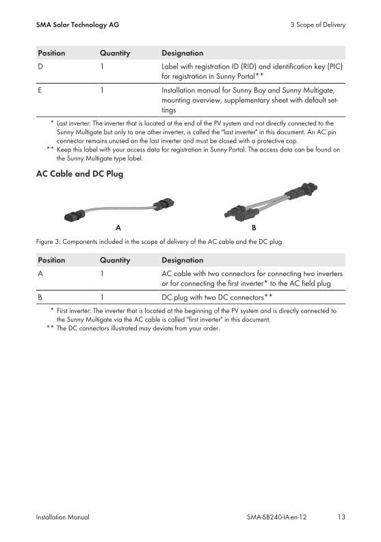
AC Cable and DC Plug
Figure 3: Components included in the scope of delivery of the AC cable and the DC plug
Position Quantity DesignationA 1 AC cable with two connectors for connecting two inverters
or for connecting the first inverter* to the AC field plug
B 1 DC plug with two DC connectors*** First inverter: The inverter that is located at the beginning of the PV system and is directly connected tothe Sunny Multigate via the AC cable is called "first inverter" in this document.
** The DC connectors illustrated may deviate from your order.
3 Scope of DeliverySMA Solar Technology AG
Installation Manual 13SMA-SB240-IA-en-12
4 Product Description
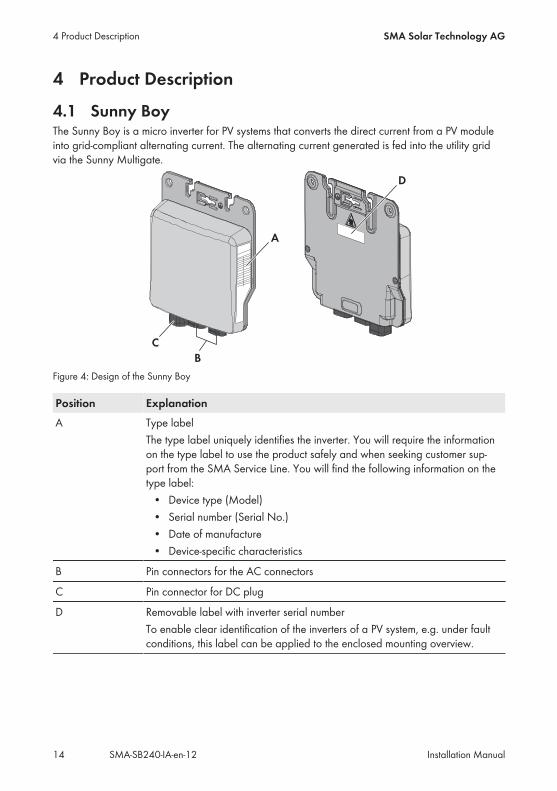
4.1 Sunny BoyThe Sunny Boy is a micro inverter for PV systems that converts the direct current from a PV moduleinto grid-compliant alternating current. The alternating current generated is fed into the utility gridvia the Sunny Multigate.
Figure 4: Design of the Sunny Boy
Position ExplanationA Type label
The type label uniquely identifies the inverter. You will require the informationon the type label to use the product safely and when seeking customer sup-port from the SMA Service Line. You will find the following information on thetype label:• Device type (Model)• Serial number (Serial No.)• Date of manufacture• Device-specific characteristics
B Pin connectors for the AC connectors
C Pin connector for DC plug
D Removable label with inverter serial numberTo enable clear identification of the inverters of a PV system, e.g. under faultconditions, this label can be applied to the enclosed mounting overview.
4 Product Description SMA Solar Technology AG
Installation ManualSMA-SB240-IA-en-1214
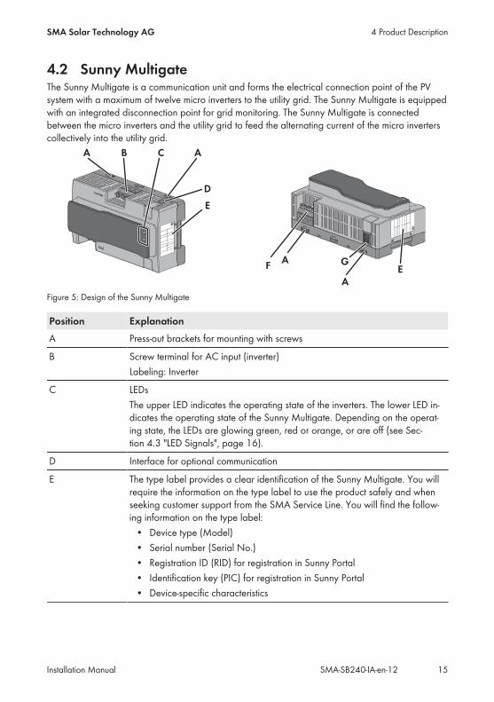
4.2 Sunny MultigateThe Sunny Multigate is a communication unit and forms the electrical connection point of the PVsystem with a maximum of twelve micro inverters to the utility grid. The Sunny Multigate is equippedwith an integrated disconnection point for grid monitoring. The Sunny Multigate is connectedbetween the micro inverters and the utility grid to feed the alternating current of the micro inverterscollectively into the utility grid.
Figure 5: Design of the Sunny Multigate
Position ExplanationA Press-out brackets for mounting with screws
B Screw terminal for AC input (inverter)Labeling: Inverter
C LEDsThe upper LED indicates the operating state of the inverters. The lower LED in-dicates the operating state of the Sunny Multigate. Depending on the operat-ing state, the LEDs are glowing green, red or orange, or are off (see Sec-tion 4.3 "LED Signals", page 16).
D Interface for optional communication
E The type label provides a clear identification of the Sunny Multigate. You willrequire the information on the type label to use the product safely and whenseeking customer support from the SMA Service Line. You will find the follow-ing information on the type label:• Device type (Model)• Serial number (Serial No.)• Registration ID (RID) for registration in Sunny Portal• Identification key (PIC) for registration in Sunny Portal• Device-specific characteristics
4 Product DescriptionSMA Solar Technology AG
Installation Manual 15SMA-SB240-IA-en-12
Position ExplanationF Screw terminal for AC output (utility grid)
Labeling: Grid
G Pin connector for connecting the network cable (RJ45)
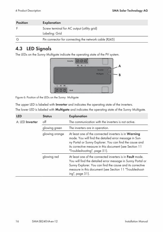
4.3 LED SignalsThe LEDs on the Sunny Multigate indicate the operating state of the PV system.
Figure 6: Position of the LEDs on the Sunny Multigate
The upper LED is labeled with Inverter and indicates the operating state of the inverters.The lower LED is labeled with Multigate and indicates the operating state of the Sunny Multigate.
LED Status ExplanationA: LED Inverter off The communication with the inverters is not active.
glowing green The inverters are in operation.
glowing orange At least one of the connected inverters is in Warningmode. You will find the detailed error message in Sun-ny Portal or Sunny Explorer. You can find the cause andits corrective measure in this document (see Section 11"Troubleshooting", page 51).
glowing red At least one of the connected inverters is in Fault mode.You will find the detailed error message in Sunny Portal orSunny Explorer. You can find the cause and its correctivemeasure in this document (see Section 11 "Troubleshoot-ing", page 51).
4 Product Description SMA Solar Technology AG
Installation ManualSMA-SB240-IA-en-1216
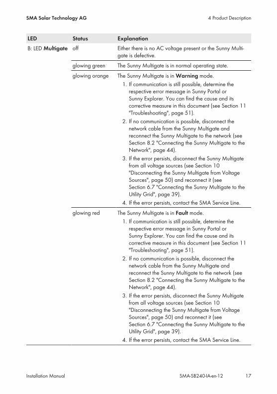
LED Status ExplanationB: LED Multigate off Either there is no AC voltage present or the Sunny Multi-
gate is defective.
glowing green The Sunny Multigate is in normal operating state.
glowing orange The Sunny Multigate is in Warning mode.1. If communication is still possible, determine therespective error message in Sunny Portal orSunny Explorer. You can find the cause and itscorrective measure in this document (see Section 11"Troubleshooting", page 51).
2. If no communication is possible, disconnect thenetwork cable from the Sunny Multigate andreconnect the Sunny Multigate to the network (seeSection 8.2 "Connecting the Sunny Multigate to theNetwork", page 44).
3. If the error persists, disconnect the Sunny Multigatefrom all voltage sources (see Section 10"Disconnecting the Sunny Multigate from VoltageSources", page 50) and reconnect it (seeSection 6.7 "Connecting the Sunny Multigate to theUtility Grid", page 39).
4. If the error persists, contact the SMA Service Line.
glowing red The Sunny Multigate is in Fault mode.1. If communication is still possible, determine therespective error message in Sunny Portal orSunny Explorer. You can find the cause and itscorrective measure in this document (see Section 11"Troubleshooting", page 51).
2. If no communication is possible, disconnect thenetwork cable from the Sunny Multigate andreconnect the Sunny Multigate to the network (seeSection 8.2 "Connecting the Sunny Multigate to theNetwork", page 44).
3. If the error persists, disconnect the Sunny Multigatefrom all voltage sources (see Section 10"Disconnecting the Sunny Multigate from VoltageSources", page 50) and reconnect it (seeSection 6.7 "Connecting the Sunny Multigate to theUtility Grid", page 39).
4. If the error persists, contact the SMA Service Line.
4 Product DescriptionSMA Solar Technology AG
Installation Manual 17SMA-SB240-IA-en-12
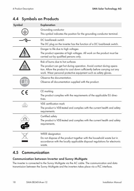
4.4 Symbols on ProductsSymbol Explanation
Grounding conductorThis symbol indicates the position for the grounding conductor terminal.
DC load-break switchThe DC plug on the inverter has the function of a DC load-break switch.
Danger to life due to high voltagesThe product operates at high voltages. All work on the product must becarried out by qualified persons only.
Risk of burns due to hot surfacesThe product can get hot during operation. Avoid contact during opera-tion. Allow the product to cool down sufficiently before carrying out anywork. Wear personal protective equipment such as safety gloves.
Observe the documentation.Observe all documentation supplied with the product.
CE markingThe product complies with the requirements of the applicable EU direc-tives.
VDE certification markThe product is VDE-tested and complies with the current health and safetyrequirements.
Certified safetyThe product is VDE-tested and complies with the current health and safetyrequirements.
WEEE designationDo not dispose of the product together with the household waste but inaccordance with the locally applicable disposal regulations for electronicwaste.
4.5 CommunicationCommunication between Inverter and Sunny MultigateThe inverter is connected to the Sunny Multigate via the AC cable. The communication and datatransmission between the Sunny Multigate and the inverters takes place via a PLC interface.
4 Product Description SMA Solar Technology AG
Installation ManualSMA-SB240-IA-en-1218
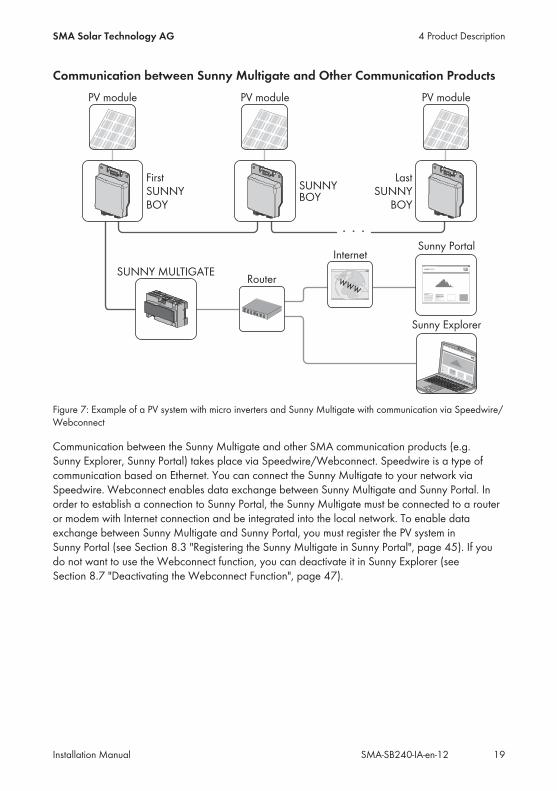
Communication between Sunny Multigate and Other Communication Products
Figure 7: Example of a PV system with micro inverters and Sunny Multigate with communication via Speedwire/Webconnect
Communication between the Sunny Multigate and other SMA communication products (e.g.Sunny Explorer, Sunny Portal) takes place via Speedwire/Webconnect. Speedwire is a type ofcommunication based on Ethernet. You can connect the Sunny Multigate to your network viaSpeedwire. Webconnect enables data exchange between Sunny Multigate and Sunny Portal. Inorder to establish a connection to Sunny Portal, the Sunny Multigate must be connected to a routeror modem with Internet connection and be integrated into the local network. To enable dataexchange between Sunny Multigate and Sunny Portal, you must register the PV system inSunny Portal (see Section 8.3 "Registering the Sunny Multigate in Sunny Portal", page 45). If youdo not want to use the Webconnect function, you can deactivate it in Sunny Explorer (seeSection 8.7 "Deactivating the Webconnect Function", page 47).
4 Product DescriptionSMA Solar Technology AG
Installation Manual 19SMA-SB240-IA-en-12
5 Mounting
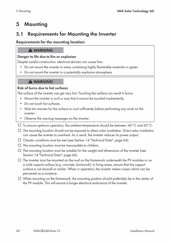
5.1 Requirements for Mounting the InverterRequirements for the mounting location:
Danger to life due to fire or explosionDespite careful construction, electrical devices can cause fires.• Do not mount the inverter in areas containing highly flammable materials or gases.• Do not mount the inverter in a potentially explosive atmosphere.
Risk of burns due to hot surfacesThe surface of the inverter can get very hot. Touching the surface can result in burns.• Mount the inverter in such a way that it cannot be touched inadvertently.• Do not touch hot surfaces.• Wait ten minutes for the surface to cool sufficiently before performing any work on theinverter.
• Observe the warning messages on the inverter.
☐ To ensure optimum operation, the ambient temperature should be between -40°C and 65°C.☐ The mounting location should not be exposed to direct solar irradiation. Direct solar irradiationcan cause the inverter to overheat. As a result, the inverter reduces its power output.
☐ Climatic conditions must be met (see Section 14 "Technical Data", page 66).☐ The mounting location must be inaccessible to children.☐ The mounting location must be suitable for the weight and dimensions of the inverter (seeSection 14 "Technical Data", page 66).
☐ The inverter must be mounted on the roof on the framework underneath the PV modules or ona solid support surface (e.g. concrete, brickwork). In living areas, ensure that the supportsurface is not drywall or similar. When in operation, the inverter makes noises which can beperceived as a nuisance.
☐ When mounting on the framework, the mounting position should preferably be in the center ofthe PV module. This will ensure a longer electrical endurance of the inverter.
5 Mounting SMA Solar Technology AG
Installation ManualSMA-SB240-IA-en-1220
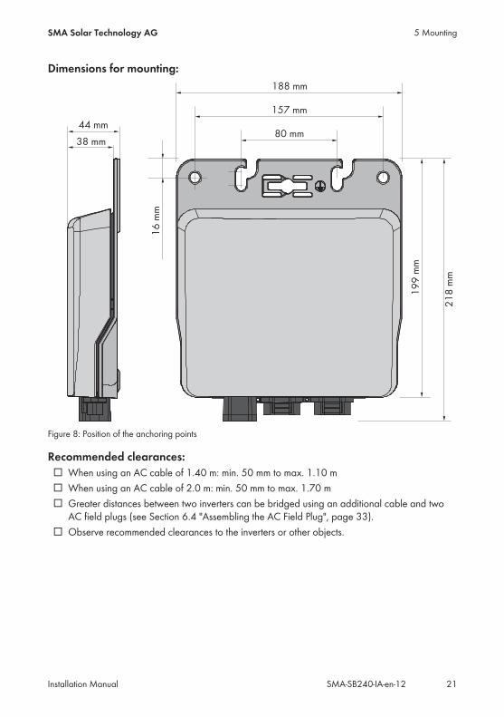
Dimensions for mounting:
Figure 8: Position of the anchoring points
Recommended clearances:☐ When using an AC cable of 1.40 m: min. 50 mm to max. 1.10 m☐ When using an AC cable of 2.0 m: min. 50 mm to max. 1.70 m☐ Greater distances between two inverters can be bridged using an additional cable and twoAC field plugs (see Section 6.4 "Assembling the AC Field Plug", page 33).
☐ Observe recommended clearances to the inverters or other objects.
5 MountingSMA Solar Technology AG
Installation Manual 21SMA-SB240-IA-en-12
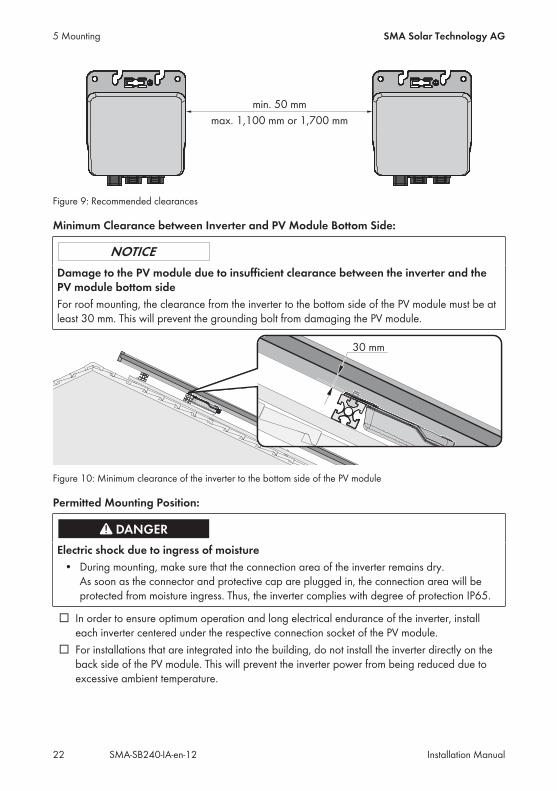
Figure 9: Recommended clearances
Minimum Clearance between Inverter and PV Module Bottom Side:
Damage to the PV module due to insufficient clearance between the inverter and thePV module bottom sideFor roof mounting, the clearance from the inverter to the bottom side of the PV module must be atleast 30 mm. This will prevent the grounding bolt from damaging the PV module.
Figure 10: Minimum clearance of the inverter to the bottom side of the PV module
Permitted Mounting Position:
Electric shock due to ingress of moisture• During mounting, make sure that the connection area of the inverter remains dry.As soon as the connector and protective cap are plugged in, the connection area will beprotected from moisture ingress. Thus, the inverter complies with degree of protection IP65.
☐ In order to ensure optimum operation and long electrical endurance of the inverter, installeach inverter centered under the respective connection socket of the PV module.
☐ For installations that are integrated into the building, do not install the inverter directly on theback side of the PV module. This will prevent the inverter power from being reduced due toexcessive ambient temperature.
5 Mounting SMA Solar Technology AG
Installation ManualSMA-SB240-IA-en-1222
5.2 Mounting the Inverter
5.2.1 Mounting the Inverter on the Roof
Risk of falling when working on the roofThere is a risk of falling or slipping when working on the rooftop. Observe the applicableaccident prevention regulations for work on rooftops.• Before stepping on the rooftop, ensure the load bearing capacity of all parts subjected toload.
• In accordance with the accident prevention regulations, a safety harness must be worn or asafety scaffold must be used.
• Use a fall protection.
When mounting the inverter on the roof underneath the PV modules, proceed as follows.You can mount the inverter with the back panel or with the enclosure lid to the roof. SMA SolarTechnology AG recommends mounting the inverter with the enclosure lid to the roof. This will allowfor better heat dissipation. Observe the minimum clearance of the inverter to the PV module (seeSection 5.1 "Requirements for Mounting the Inverter", page 20).
Information on the figures in this sectionThe figures show the recommended mounting option for the inverter with the lid facing theroof. The procedure for mounting the inverter with the back panel facing the roof is identicaland is not depicted in the figures in this section.
Position of the inverterIn order to ensure optimum operation and long electrical endurance of the inverter, installeach inverter centered under the respective junction box of the PV module.
Additionally required mounting material (not included in the scope of delivery):☐ The required fastening material must be selected according to the profile rail used.☐ The mounting material must be made of stainless steel.☐ Diameter of the screws: maximum 8 mm
Damage to the PV module due to screws being too longThe length of the screws must be suitable for the clearance between the inverter and the PVmodule bottom side.• Make sure that the PV module is not damaged by the screws being used.
There are several options for attaching the inverter to the framework on the roof. In the followingexample, mounting with T-head bolts is described.
5 MountingSMA Solar Technology AG
Installation Manual 23SMA-SB240-IA-en-12
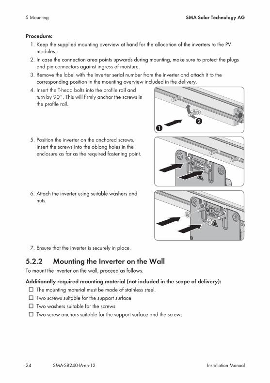
Procedure:1. Keep the supplied mounting overview at hand for the allocation of the inverters to the PVmodules.
2. In case the connection area points upwards during mounting, make sure to protect the plugsand pin connectors against ingress of moisture.
3. Remove the label with the inverter serial number from the inverter and attach it to thecorresponding position in the mounting overview included in the delivery.
4. Insert the T-head bolts into the profile rail andturn by 90°. This will firmly anchor the screws inthe profile rail.
5. Position the inverter on the anchored screws.Insert the screws into the oblong holes in theenclosure as far as the required fastening point.
6. Attach the inverter using suitable washers andnuts.
7. Ensure that the inverter is securely in place.
5.2.2 Mounting the Inverter on the WallTo mount the inverter on the wall, proceed as follows.
Additionally required mounting material (not included in the scope of delivery):☐ The mounting material must be made of stainless steel.☐ Two screws suitable for the support surface☐ Two washers suitable for the screws☐ Two screw anchors suitable for the support surface and the screws
5 Mounting SMA Solar Technology AG
Installation ManualSMA-SB240-IA-en-1224
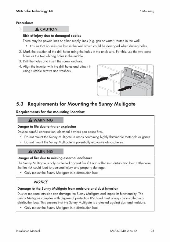
Procedure:1.
Risk of injury due to damaged cablesThere may be power lines or other supply lines (e.g. gas or water) routed in the wall.• Ensure that no lines are laid in the wall which could be damaged when drilling holes.
2. Mark the position of the drill holes using the holes in the enclosure. For this, use the two outerholes or the two oblong holes in the middle.
3. Drill the holes and insert the screw anchors.4. Align the inverter with the drill holes and attach itusing suitable screws and washers.
5.3 Requirements for Mounting the Sunny MultigateRequirements for the mounting location:
Danger to life due to fire or explosionDespite careful construction, electrical devices can cause fires.• Do not mount the Sunny Multigate in areas containing highly flammable materials or gases.• Do not mount the Sunny Multigate in potentially explosive atmospheres.
Danger of fire due to missing external enclosureThe Sunny Multigate is only protected against fire if it is installed in a distribution box. Otherwise,the fire risk could lead to personal injury and property damage.• Only mount the Sunny Multigate in a distribution box.
Damage to the Sunny Multigate from moisture and dust intrusionDust or moisture intrusion can damage the Sunny Multigate and impair its functionality. TheSunny Multigate complies with degree of protection IP20 and must always be installed in adistribution box. This ensures that the Sunny Multigate is protected against dust and moisture.• Only mount the Sunny Multigate in a distribution box.
5 MountingSMA Solar Technology AG
Installation Manual 25SMA-SB240-IA-en-12

☐ The mounting location must be suitable for the installation of the Sunny Multigate in adistribution box.
☐ The mounting location must be suitable for the weight and dimensions of the Sunny Multigate(see Section 14 "Technical Data", page 66).
☐ The mounting location must be inaccessible to children.☐ AC cable route of the entire PV system with Sunny Multigate: maximum 30 mWhen installing several Sunny Multigate devices in a PV system, you must lay the AC cable ofeach Sunny Multigate to the respective inverter separately in order to guarantee trouble-freecommunication between the Sunny Multigate and the inverter.
Figure 11: Maximum AC cable route of the PV system (left: last inverter; right: first inverter connected toSunny Multigate).
☐ A robust support surface must be available for mounting the device, e.g. concrete, walls. Inliving areas, ensure that the support surface is not drywall or similar.
☐ The mounting location should be freely and safely accessible at all times without the need forany auxiliary equipment (such as scaffolding or lifting platforms). Non-fulfillment of thesecriteria may restrict servicing.
☐ The mounting location should not be exposed to direct solar irradiation.☐ Climatic conditions must be met (see Section 14 "Technical Data", page 66).☐ The ambient temperature must be between -40°C and 25°C. This will ensure optimaloperation of the Sunny Multigate.
Clearances:☐ The clearance inside a metal distribution box must be at least 12.7 mm to walls or othercomponents.
☐ Within an industrial closure, observe the following clearances to ensure sufficient ventilation:
5 Mounting SMA Solar Technology AG
Installation ManualSMA-SB240-IA-en-1226

Figure 12: Recommended clearances
Position DimensionsA 98 mm
B 150 mm
Permitted mounting positions of the Sunny Multigate:☐ Only mount the Sunny Multigate horizontally.
Dimensions for mounting the Sunny Multigate with screws:
Figure 13: Dimensions of the Sunny Multigate and the drill holes for mounting with screws
5 MountingSMA Solar Technology AG
Installation Manual 27SMA-SB240-IA-en-12
5.4 Mounting the Sunny Multigate
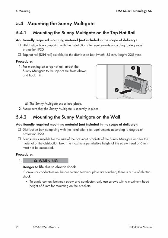
5.4.1 Mounting the Sunny Multigate on the Top-Hat RailAdditionally required mounting material (not included in the scope of delivery):☐ Distribution box complying with the installation site requirements according to degree ofprotection IP20
☐ Top-hat rail (DIN rail) suitable for the distribution box (width: 35 mm, length: 235 mm).
Procedure:1. For mounting on a top-hat rail, attach theSunny Multigate to the top-hat rail from above,and hook it in.
☑ The Sunny Multigate snaps into place.2. Make sure that the Sunny Multigate is securely in place.
5.4.2 Mounting the Sunny Multigate on the WallAdditionally required mounting material (not included in the scope of delivery):☐ Distribution box complying with the installation site requirements according to degree ofprotection IP20
☐ Four screws suitable for the size of the press-out brackets of the Sunny Multigate and for thematerial of the distribution box. The maximum permissible height of the screw head of 6 mmmust not be exceeded.
Procedure:1.
Danger to life due to electric shockIf screws or conductors on the connecting terminal plate are touched, there is a risk of electricshock.• To avoid contact between screw and conductor, only use screws with a maximum headheight of 6 mm for mounting on the brackets.
5 Mounting SMA Solar Technology AG
Installation ManualSMA-SB240-IA-en-1228

2. Press the four brackets on the back side of theSunny Multigate out from the inside.
☑ The brackets snap audibly into place.3. Mark the drill holes using the brackets as a template.4. Drill the holes.5. Insert screws with a maximum head height of6 mm through the brackets and tighten. Makesure not to damage the brackets.
6. Make sure that the Sunny Multigate is securely in place.
5 MountingSMA Solar Technology AG
Installation Manual 29SMA-SB240-IA-en-12
6 Electrical Connection
6.1 Safety during Electrical Connection
Risk of electric shock due to contact with live components when opening theSunny MultigateThere are live components inside the Sunny Multigate. There is a risk of electric shock if you openthe Sunny Multigate.• Never open the Sunny Multigate.
Damage to the inverter due to moisture ingressWhen the inverter is open, moisture can penetrate and cause damage to the inverter. Thetightness is no longer intact and the function of the inverter cannot be guaranteed.• Never open the inverter.
6.2 Overview of the Connection Areas
6.2.1 Sunny Boy
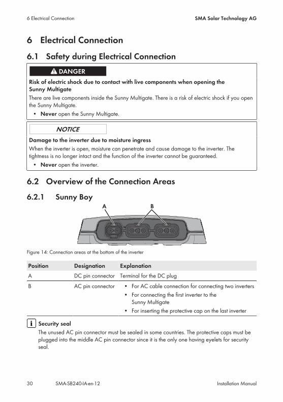
Figure 14: Connection areas at the bottom of the inverter
Position Designation ExplanationA DC pin connector Terminal for the DC plug
B AC pin connector • For AC cable connection for connecting two inverters• For connecting the first inverter to theSunny Multigate
• For inserting the protective cap on the last inverter
Security sealThe unused AC pin connector must be sealed in some countries. The protective caps must beplugged into the middle AC pin connector since it is the only one having eyelets for securityseal.
6 Electrical Connection SMA Solar Technology AG
Installation ManualSMA-SB240-IA-en-1230
6.2.2 Sunny Multigate
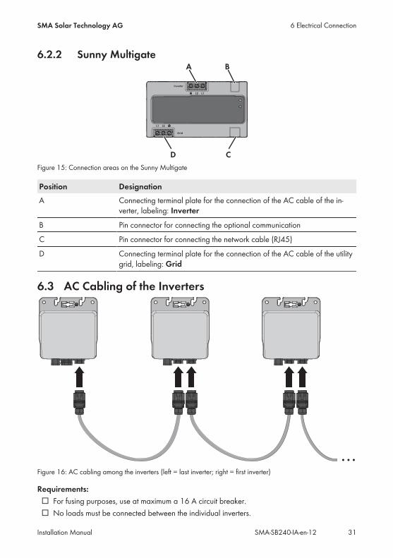
Figure 15: Connection areas on the Sunny Multigate
Position DesignationA Connecting terminal plate for the connection of the AC cable of the in-
verter, labeling: Inverter
B Pin connector for connecting the optional communication
C Pin connector for connecting the network cable (RJ45)
D Connecting terminal plate for the connection of the AC cable of the utilitygrid, labeling: Grid
6.3 AC Cabling of the Inverters
Figure 16: AC cabling among the inverters (left = last inverter; right = first inverter)
Requirements:☐ For fusing purposes, use at maximum a 16 A circuit breaker.☐ No loads must be connected between the individual inverters.
6 Electrical ConnectionSMA Solar Technology AG
Installation Manual 31SMA-SB240-IA-en-12

☐ For the AC cable connection to the Sunny Boy, only use the AC cable recommended bySMA Solar Technology AG (see Section 15 "Spare Parts and Accessories", page 72).
☐ To allow for greater distances between two inverters, use the AC field plug (see Section 6.4"Assembling the AC Field Plug", page 33).
Procedure:1.
Danger to life due to electric shockDo not disconnect the AC connectors under load.• Ensure that the circuit breaker is switched off and that it cannot be reconnected.• Make sure that the PV modules are covered.
2. Plug one end of the supplied AC cable into theouter AC pin connector of the last inverter of thePV system.
☑ The plug snaps into place.3. Plug the protective cap into the middle AC pinconnector of the last inverter.
☑ The protective cap snaps into place.4. Seal the protective cap, if necessary. Make sure that the AC cable of the last inverter isplugged into the outer AC pin connector. Only the middle AC pin connector can be used forthe security seal since it is the only one having eyelets for the security seal.
5. Ensure that the AC connector and the protective cap in the inverter pin connectors are securelyin place.
6. Plug the other end of the AC cable into themiddle AC pin connector of the next inverter.
☑ The plug snaps into place.7. Connect further inverters following the same procedure.
6 Electrical Connection SMA Solar Technology AG
Installation ManualSMA-SB240-IA-en-1232
8. If necessary, use AC field plugs to bridge greater distances (see Section 6.4 "Assembling theAC Field Plug", page 33).
9. If necessary, additionally ground the inverters (see Section 6.5 "Connecting AdditionalGrounding", page 36).
10. Connect the free end of the AC cable of the first inverter to the Sunny Multigate (seeSection 6.6, page 36).
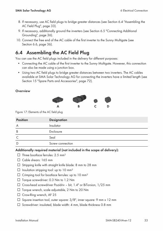
6.4 Assembling the AC Field PlugYou can use the AC field plugs included in the delivery for different purposes:• Connecting the AC cable of the first inverter to the Sunny Multigate. However, this connectioncan also be made using a junction box.
• Using two AC field plugs to bridge greater distances between two inverters. The AC cablesavailable at SMA Solar Technology AG for connecting the inverters have a limited length (seeSection 15 "Spare Parts and Accessories", page 72).
Overview
Figure 17: Elements of the AC field plug
Position DesignationA Insulator
B Enclosure
C Seal
D Screw connection
Additionally required material (not included in the scope of delivery):☐ Three bootlace ferrules: 2.5 mm²☐ Cable shears: 165 mm☐ Stripping knife with straight knife blade: 8 mm to 28 mm☐ Insulation stripping tool: up to 10 mm²☐ Crimping tool for bootlace ferrules: up to 10 mm²☐ Torque screwdriver: 0.3 Nm to 1.2 Nm☐ Cross-head screwdriver Pozidriv – bit, 1.4" or BiTorsion, 1/25 mm☐ Torque wrench, scale adjustable, 2 Nm to 20 Nm☐ Crow-Ring wrench, AF 25☐ Square insertion tool, outer square: 3/8", inner square: 9 mm x 12 mm☐ Screwdriver: insulated, blade width: 4 mm, blade thickness 0.8 mm
6 Electrical ConnectionSMA Solar Technology AG
Installation Manual 33SMA-SB240-IA-en-12
Danger to life due to electric shock• Do not disconnect or connect the AC field plug under load.• Only assemble the AC field plug in a dry environment.• Observe the operating temperature range of −40°C to +85°C.
Cable requirements:☐ Cable cross-section: 2.5 mm²☐ Temperature-resistant up to at least +90°C☐ External diameter of the cable sheath: 9.6 mm to 10 mm☐ Number of stranded wires: 46☐ Cable type: copper wire, tin-plated☐ Wire cross-section: 0.25 mm²
Removing and reassembling the AC field plug is only possible within 72 hours• In total, the AC field plug may at maximum be removed three times and only within thefirst 72 hours after the first assembly.
• After the period of 72 hours has expired, the AC field plug must not be removed.• The cable must be shortened again before each assembly.• Only disconnect and disassemble the AC field plug following the instructions in thisdocument (see Section 13.1 "Disconnecting the AC Field Plug", page 64).
Procedure:To assemble and connect the AC field plug, carry out the following steps in the given sequence. Theexact procedure is described in the paragraphs below.• Assembling the Cable• Premounting the AC Field Plug• Mounting the Insulator• Completing Mounting of the AC Field Plug
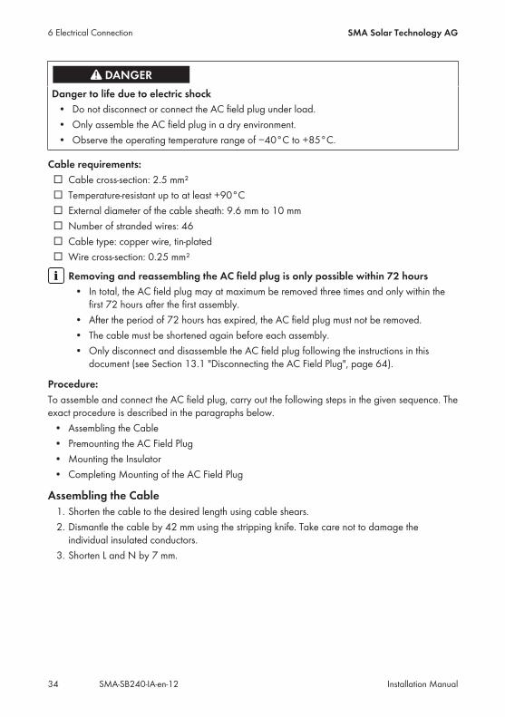
Assembling the Cable1. Shorten the cable to the desired length using cable shears.2. Dismantle the cable by 42 mm using the stripping knife. Take care not to damage theindividual insulated conductors.
3. Shorten L and N by 7 mm.
6 Electrical Connection SMA Solar Technology AG
Installation ManualSMA-SB240-IA-en-1234
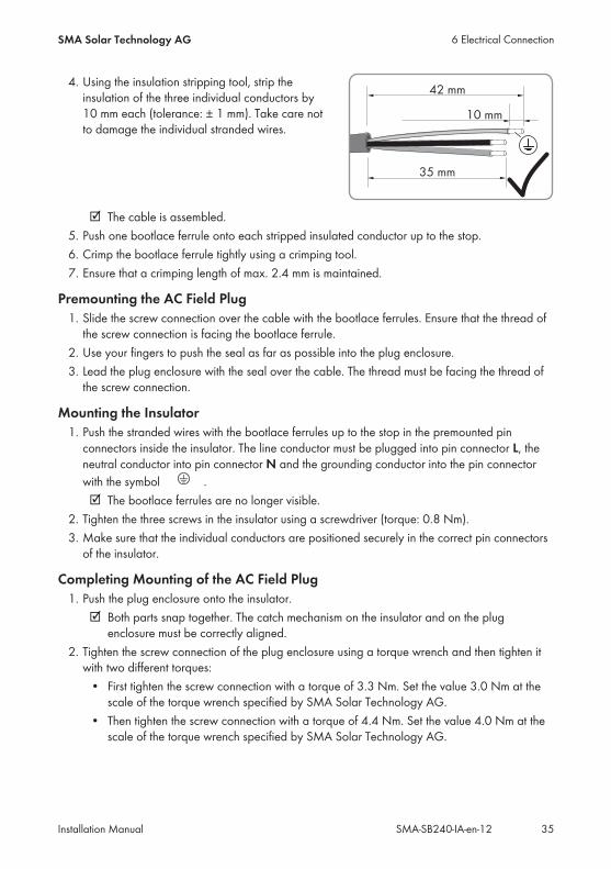
4. Using the insulation stripping tool, strip theinsulation of the three individual conductors by10 mm each (tolerance: ± 1 mm). Take care notto damage the individual stranded wires.
☑ The cable is assembled.5. Push one bootlace ferrule onto each stripped insulated conductor up to the stop.6. Crimp the bootlace ferrule tightly using a crimping tool.7. Ensure that a crimping length of max. 2.4 mm is maintained.
Premounting the AC Field Plug1. Slide the screw connection over the cable with the bootlace ferrules. Ensure that the thread ofthe screw connection is facing the bootlace ferrule.
2. Use your fingers to push the seal as far as possible into the plug enclosure.3. Lead the plug enclosure with the seal over the cable. The thread must be facing the thread ofthe screw connection.
Mounting the Insulator1. Push the stranded wires with the bootlace ferrules up to the stop in the premounted pinconnectors inside the insulator. The line conductor must be plugged into pin connector L, theneutral conductor into pin connector N and the grounding conductor into the pin connectorwith the symbol .☑ The bootlace ferrules are no longer visible.
2. Tighten the three screws in the insulator using a screwdriver (torque: 0.8 Nm).3. Make sure that the individual conductors are positioned securely in the correct pin connectorsof the insulator.
Completing Mounting of the AC Field Plug1. Push the plug enclosure onto the insulator.☑ Both parts snap together. The catch mechanism on the insulator and on the plugenclosure must be correctly aligned.
2. Tighten the screw connection of the plug enclosure using a torque wrench and then tighten itwith two different torques:• First tighten the screw connection with a torque of 3.3 Nm. Set the value 3.0 Nm at thescale of the torque wrench specified by SMA Solar Technology AG.
• Then tighten the screw connection with a torque of 4.4 Nm. Set the value 4.0 Nm at thescale of the torque wrench specified by SMA Solar Technology AG.
6 Electrical ConnectionSMA Solar Technology AG
Installation Manual 35SMA-SB240-IA-en-12
• Hint: The given torque setting only applies to the torque wrench specified by SMA SolarTechnology AG. The value to be set on the torque wrench is lower than the actual value(for more information on the calculation of the torque to be set, go to www.stahlwille.com). A torque wrench consists of the following components: torque wrench (basic device),square insertion tool and crow's foot wrench.
3. Make sure that the screw connection of the plug enclosure is securely fastened.
6.5 Connecting Additional GroundingIf a second grounding conductor or equipotential bonding is locally required, you can also groundthe inverter enclosure. This prevents touch current if the original grounding conductor fails.You can ground each inverter separately or connect several inverters with one another.
Procedure:• Connect the grounding conductor to the equipotential bonding of the AC distribution board.
6.6 Connecting the First Inverter to the Sunny Multigate
6.6.1 Connecting the AC Cable to the AC Field Plug or to theJunction Box
There are two ways to connect the first inverter to the Sunny Multigate on the AC side:• Connection with the AC field plug included in the delivery• Connection via a junction box with integrated feed-through terminal
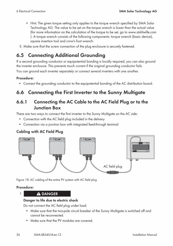
Cabling with AC Field Plug
Figure 18: AC cabling of the entire PV system with AC field plug
Procedure:1.
Danger to life due to electric shockDo not connect the AC field plug under load.• Make sure that the two-pole circuit breaker of the Sunny Multigate is switched off andcannot be reconnected.
• Make sure that the PV modules are covered.
6 Electrical Connection SMA Solar Technology AG
Installation ManualSMA-SB240-IA-en-1236
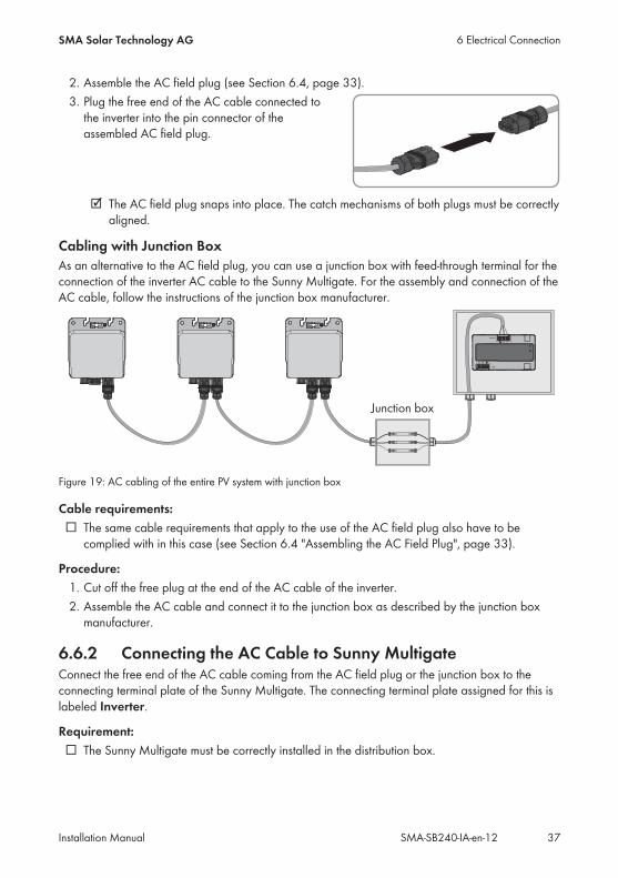
2. Assemble the AC field plug (see Section 6.4, page 33).3. Plug the free end of the AC cable connected tothe inverter into the pin connector of theassembled AC field plug.
☑ The AC field plug snaps into place. The catch mechanisms of both plugs must be correctlyaligned.
Cabling with Junction BoxAs an alternative to the AC field plug, you can use a junction box with feed-through terminal for theconnection of the inverter AC cable to the Sunny Multigate. For the assembly and connection of theAC cable, follow the instructions of the junction box manufacturer.
Figure 19: AC cabling of the entire PV system with junction box
Cable requirements:☐ The same cable requirements that apply to the use of the AC field plug also have to becomplied with in this case (see Section 6.4 "Assembling the AC Field Plug", page 33).
Procedure:1. Cut off the free plug at the end of the AC cable of the inverter.2. Assemble the AC cable and connect it to the junction box as described by the junction boxmanufacturer.
6.6.2 Connecting the AC Cable to Sunny MultigateConnect the free end of the AC cable coming from the AC field plug or the junction box to theconnecting terminal plate of the Sunny Multigate. The connecting terminal plate assigned for this islabeled Inverter.
Requirement:☐ The Sunny Multigate must be correctly installed in the distribution box.
6 Electrical ConnectionSMA Solar Technology AG
Installation Manual 37SMA-SB240-IA-en-12

Cable requirements for use of AC field plug:☐ When using the AC field plug, observe the cable requirements for assembling the AC fieldplug (see Section 6.6.1 "Connecting the AC Cable to the AC Field Plug or to the JunctionBox", page 36)
Cable requirements for use of junction box:☐ Cable cross-section: 2.5 mm²☐ Temperature-resistant up to at least +90°C☐ External diameter of the cable sheath: 9.6 mm to 10 mm☐ Number of stranded wires: 46☐ Cable type: copper wire, tin-plated☐ Wire cross-section: 0.25 mm²
Installation of several Sunny Multigate devicesWhen installing several Sunny Multigate devices in a PV system, a three-wire cable withgrounding conductor must be used for each Sunny Multigate in order to guarantee trouble-free communication between the Sunny Multigate and the inverter.
Procedure:1.
Danger to life due to electric shock• Ensure that the circuit breaker is switched off and that it cannot be reconnected.• Make sure that the PV modules are covered.
2. When using a junction box, assemble the AC cable and connect it to the junction box inaccordance with the instructions of the manufacturer.
3. Route the AC cable from the AC field plug or the junction box to the terminal Inverter of theSunny Multigate.
4. Dismantle the AC cable to the desired length.5. Strip the insulation of the three AC cable conductors by 8 mm each.6.
Damage to the Sunny Multigate due to incorrectly connected conductorsIf PE and L or N are swapped, the Sunny Multigate could be damaged during commissioning.• Be sure to observe the terminal labels on the Sunny Multigate.• Connect all conductors in accordance with the terminal labels.– Connect the grounding conductor of the AC cable to the terminal PE of theSunny Multigate. Make sure that the conductor is inserted into the terminal right upto the stop.
– Connect the line conductor of the AC cable to the terminal L of the Sunny Multigate.Make sure that the conductor is inserted into the terminal right up to the stop.
– Connect the neutral conductor of the AC cable to the terminal N of the SunnyMultigate. Make sure that the conductor is inserted into the terminal right up to thestop.
6 Electrical Connection SMA Solar Technology AG
Installation ManualSMA-SB240-IA-en-1238

7. Tighten all three screws of the connecting terminal plate using a flat-blade screwdriver (torque:0.6 Nm).
8. Make sure that all terminals are correctlyallocated.
9. Make sure that all conductors are securely in place.
6.7 Connecting the Sunny Multigate to the Utility GridConnect the AC cable of the utility grid to the connecting terminal plate of the Sunny Multigatelabeled Grid according to the following procedure:
Cable requirements:☐ Only use copper cables.☐ Use only cables made of solid wire or stranded wires.☐ Temperature-resistant up to at least +90°C☐ Conductor cross-section: 1.5 mm² to 6.0 mm²
Requirement:☐ The Sunny Multigate must be correctly installed in the distribution box.☐ If an external residual-current device is required, install a type A residual-current device whichtrips at a residual current of 100 mA or higher (for details on selecting a residual-currentdevice, see the Technical Information "Criteria for Selecting a Residual-Current Device" atwww.SMA-Solar.com).
☐ If the Sunny Multigate is being commissioned in Italy, an external grid and PV systemprotection (SPI) in accordance with the CEI 0-21 standard must additionally be installed.
Overvoltage category:The Sunny Multigate can be deployed in utility grids of installation category III or lower, as definedin IEC 60664-1. This means that the Sunny Multigate can be permanently connected to the originof an utility grid in a building. In installations involving long outdoor cable routes, additionalmeasures for overvoltage suppression must be taken so that the overvoltage category is reducedfrom IV to III.
Procedure:1.
Danger to life due to electric shock• Ensure that the circuit breaker is switched off and that it cannot be reconnected.
6 Electrical ConnectionSMA Solar Technology AG
Installation Manual 39SMA-SB240-IA-en-12
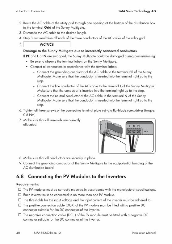
2. Route the AC cable of the utility grid through one opening at the bottom of the distribution boxto the terminal Grid of the Sunny Multigate.
3. Dismantle the AC cable to the desired length.4. Strip 8 mm insulation off each of the three conductors of the AC cable of the utility grid.5.
Damage to the Sunny Multigate due to incorrectly connected conductorsIf PE and L or N are swapped, the Sunny Multigate could be damaged during commissioning.• Be sure to observe the terminal labels on the Sunny Multigate.• Connect all conductors in accordance with the terminal labels.– Connect the grounding conductor of the AC cable to the terminal PE of the SunnyMultigate. Make sure that the conductor is inserted into the terminal right up to thestop.
– Connect the line conductor of the AC cable to the terminal L of the Sunny Multigate.Make sure that the conductor is inserted into the terminal right up to the stop.
– Connect the neutral conductor of the AC cable to the terminal N of the SunnyMultigate. Make sure that the conductor is inserted into the terminal right up to thestop.
6. Tighten all three screws of the connecting terminal plate using a flat-blade screwdriver (torque:0.6 Nm).
7. Make sure that all terminals are correctlyallocated.
8. Make sure that all conductors are securely in place.9. Connect the grounding conductor of the Sunny Multigate to the equipotential bonding of theAC distribution board.
6.8 Connecting the PV Modules to the InvertersRequirements:☐ The PV modules must be correctly mounted in accordance with the manufacturer specifications.☐ Each inverter must be connected to no more than one PV module.☐ The thresholds for the input voltage and the input current of the inverter must be adhered to.☐ The positive connection cable (DC+) of the PV module must be fitted with a positive DCconnector suitable for the DC connector of the inverter.
☐ The negative connection cable (DC−) of the PV module must be fitted with a negative DCconnector suitable for the DC connector of the inverter.
6 Electrical Connection SMA Solar Technology AG
Installation ManualSMA-SB240-IA-en-1240

Procedure:1.
Danger to life due to electric shockDo not disconnect the AC connector under load.• Ensure that the circuit breaker is switched off and that it cannot be reconnected.• Ensure that the PV module is covered.
2. Check the PV module for ground faults (see Section 11.2, page 61).3. Check the DC connectors of the PV module for correct polarity and connect to the DCconnectors of the supplied DC plug. Tip: for correct assignment, the DC plug is marked with +and ‒.☑ The DC connectors snap into place.
4. Make sure that the DC connectors are securely in place.5. Insert the DC plug with the DC connectors intothe outer pin connector on the inverter.
6 Electrical ConnectionSMA Solar Technology AG
Installation Manual 41SMA-SB240-IA-en-12
7 Commissioning the PV SystemRequirements:☐ The Sunny Multigate must be correctly installed in the distribution box.☐ The country data set must be configured according to the country or purpose. You can find theconfigured country data set on the enclosed supplementary sheet with the default settings.
☐ The AC cable of the utility grid must be correctly connected to the Sunny Multigate. Allconductors must be connected in accordance with the terminal labels. No conductors must beswapped.
☐ The circuit breaker must be correctly rated.☐ All inverters must be correctly mounted.☐ All DC and AC connectors must be firmly plugged in.☐ The connection areas of all inverters must be dry and sealed rain-tight by means of connectorsand, where applicable, a protective cap.
☐ The unused AC pin connector on the last inverter of the PV system must be sealed with aprotective cap.
☐ The first inverter of the PV system must be correctly connected to the Sunny Multigate via theAC cable. All conductors must be connected in accordance with the terminal labels. Noconductors must be swapped.
☐ The PV modules must be correctly mounted.
Damage to the Sunny Multigate due to incorrectly connected conductorsIf PE and L or N are swapped, the Sunny Multigate could be damaged during commissioning.• Be sure to observe the terminal labels on the Sunny Multigate.• All conductors must be connected in accordance with the terminal labels.• Make sure that all terminals are correctly allocated.
7 Commissioning the PV System SMA Solar Technology AG
Installation ManualSMA-SB240-IA-en-1242
Procedure:• Switch on the circuit breaker.☑ Both LEDs on the Sunny Multigate are glowing green. Feed-in operation begins.✖ The LED Inverter is off?There is a disturbance in the PV system.• Eliminate the disturbance (see Section 11 "Troubleshooting", page 51). You will find thedetailed error message in Sunny Portal or Sunny Explorer.
✖ The LED Inverter on the Sunny Multigate is glowing orange or red?There is a disturbance in at least one of the connected inverters.• Eliminate the disturbance (see Section 11 "Troubleshooting", page 51). You will find thedetailed error message in Sunny Portal or Sunny Explorer.
✖ The LED Multigate on the Sunny Multigate is glowing orange or red?There is a disturbance in the Sunny Multigate.• Eliminate the disturbance (see Section 4.3 "LED Signals", page 16).
7 Commissioning the PV SystemSMA Solar Technology AG
Installation Manual 43SMA-SB240-IA-en-12
8 Configuration
8.1 Configuration ProcedureOnce you have commissioned the PV system, you may have to adjust various settings via acommunication product. This section describes the procedure for configuration and gives anoverview of the steps you must perform in the prescribed order.
Procedure See1. If you want to integrate the PV system into a Speedwire
network, connect the Sunny Multigate to the network.Section 8.2, page 44
2. To manage the PV system data or to set the operating pa-rameters, capture the Sunny Multigate in a communicationproduct.
Section 8.3, page 45 andSection 8.4, page 46
3. Change the PV system time and PV system password. Manual of the communica-tion product at www.SMA-Solar.com
4. Check which country data set the Sunny Multigate is setto.
Supplementary sheet withdefault settings
5. If the country data set is not set correctly for your countryor your purpose, adjust to the required country data set.
Section 8.6, page 47
8.2 Connecting the Sunny Multigate to the NetworkYou can configure the Sunny Multigate and the inverters using an SMA communication product(e.g. Sunny Portal, Sunny Explorer).In order to register your PV system in Sunny Portal, you must connect the Sunny Multigate to thelocal network.
Required material (not included in the scope of delivery):☐ One network cable
Cable requirements:The cable length and quality affect the quality of the signal. Observe the following cablerequirements.☐ Cable type: 100BaseTx SMA Solar Technology AG recommends cable type "SMA COMCAB-OUTxxx" for outdooruse and cable type "SMA COMCAB-INxxx" for indoor use, available in lengths xxx = 100 m,200 m, 500 m, 1,000 m
☐ Cable category: Cat5, Cat5e, Cat6, Cat6a or Cat7☐ Plug type: RJ45 of Cat5, Cat5e, Cat6 or Cat6a☐ Shielding: SF/UTP, S/UTP, SF/FTP or S/FTP☐ Number of insulated conductor pairs and insulated conductor cross-section: at least2 x 2 x 0.22 mm²
8 Configuration SMA Solar Technology AG
Installation ManualSMA-SB240-IA-en-1244
☐ Maximum cable length between two nodes when using patch cables: 50 m☐ Maximum cable length between two nodes when using installation cables: 100 m☐ UV-resistant for outdoor use
Requirements:☐ The PV system must be commissioned (see Section 7 "Commissioning the PV System", page 42).
☐ A computer with an Ethernet interface must be available.
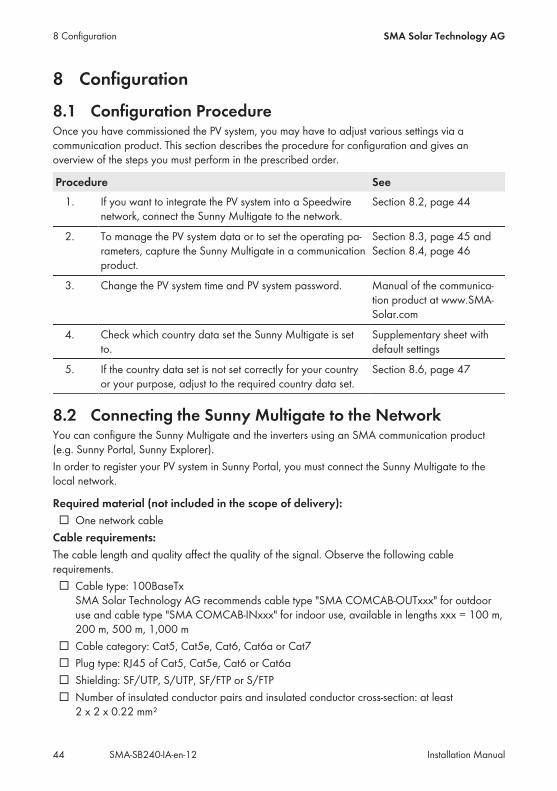
Procedure:1. Connect one end of the network cable to the router or directly to the computer.2. Plug the other end of the network cable into thepin connector at the bottom of the SunnyMultigate.
☑ The green LED in the pin connector is glowing or flashing. The Sunny Multigate is connected tothe router or the computer.
☑ The green LED in the pin connector is glowing or flashing and the yellow LED is glowing: A100 Mbit connection to the router or the computer is established.
✖ All LEDs in the pin connector are off.Possible failure cause: the other end of the network cable is not correctly attached or there isno voltage supply.• Make sure that the router or computer is supplied with voltage.• Make sure that the network cable is correctly attached.• If the network cable is correctly attached and the problem persists, contact the SMAService Line (see Section 16 "Contact", page 74).
8.3 Registering the Sunny Multigate in Sunny PortalIf you want to use the Webconnect function and monitor your PV system in Sunny Portal, you mustregister the Sunny Multigate in Sunny Portal.
Requirements:☐ The PV system must be commissioned (see Section 7 "Commissioning the PV System", page 42).
☐ The Sunny Multigate must be connected to a router or modem with Internet access and mustbe integrated in the local network. If the router or the modem does not support DHCP, or ifDHCP is deactivated, you can use the SMA Connection Assist to integrate the Sunny Multigateinto your network (see www.SMA-Solar.com).
☐ All UDP ports > 1024 on the router or modem must be open for outgoing connections. If thereis a firewall installed on the router or modem, you might have to adjust the firewall rules.
8 ConfigurationSMA Solar Technology AG
Installation Manual 45SMA-SB240-IA-en-12
☐ It must be possible for the outgoing router or modem connections to reach all Internetdestinations (target IP, target port). If there is a firewall installed on the router or modem, youmight have to adjust the firewall rules.
☐ On a router or modem with NAT (Network Address Translation) there must not be any portforwarding. Potential communication problems can thus be prevented.
☐ There must be no packet filtering and no manipulation for SIP packets on the router or modem.☐ The registration ID (RID) and identification key (PIC) for registration in Sunny Portal must beavailable (see type label on the Sunny Multigate or enclosed label).
Procedure:• Register the Sunny Multigate in Sunny Portal (see the User Manual "Micro Inverters inSunny Portal" at www.SunnyPortal.com). Useful hint: The PV System Setup Assistant guides you through user registration and theregistration of your PV system in Sunny Portal.
8.4 Connecting the Sunny Multigate to Sunny ExplorerRequirements:☐ The PV system must be commissioned (see Section 7 "Commissioning the PV System", page 42).
☐ A computer with an Ethernet interface must be available.☐ The Sunny Multigate must be connected to the network.☐ Sunny Explorer from software version 1.06 must be installed on the computer.
Procedure:• Start Sunny Explorer and create a PV system (see Sunny Explorer user manual at www.SMA-Solar.com).
8.5 Changing Operating ParametersThis section describes the basic procedure for changing operating parameters. Always changeoperating parameters as described in this section.The operating parameters of the Sunny Multigate are set to certain values by default. You canchange the operating parameters after commissioning using Sunny Explorer to optimize theoperation of the inverter.
Requirements:☐ The PV system must be commissioned (see Section 7 "Commissioning the PV System", page 42).
☐ A computer with an Ethernet interface must be available.☐ Sunny Explorer from software version 1.06 must be installed on the computer.☐ The system must be registered in Sunny Explorer.
8 Configuration SMA Solar Technology AG
Installation ManualSMA-SB240-IA-en-1246

☐ The changes to the grid-relevant parameters must be approved by the responsible gridoperator.
☐ When changing grid-relevant parameters, the SMA Grid Guard code must be available (seethe Certificate "Order Form for the SMA Grid Guard Code" at www.SMA-Solar.com).
Procedure:1. Access the Sunny Explorer user interface.2. If required, enter the SMA Grid Guard code.3. Select and set the desired parameter.4. Save settings.
8.6 Configuring the Country Data SetBy default, the Sunny Multigate is set to a specific country data set. You can find the country dataset to which the Sunny Multigate has been set on the enclosed supplementary sheet with the defaultsettings or on the type label. Each country data set contains various operating parameters, whichcan be individually set according to the respective country. You can change the parameters bymeans of a communication product.
The country data set must be set correctly.If you select a country data set which is not valid for your country and purpose, it can cause adisturbance in the PV system and lead to problems with the grid operator. When selecting thecountry data set, you must always observe the locally applicable standards and directives aswell as the properties of the PV system (e.g. PV system size, grid-connection point).• If you are not sure which country data set is valid for your country or purpose, contactyour grid operator for information on which country data set is to be configured.
The basic procedure for changing operating parameters is explained in another section (seeSection 8.5 "Changing Operating Parameters", page 46).
Procedure:• Select the parameter Default or Set country standard and adjust the required country dataset.
8.7 Deactivating the Webconnect FunctionRequirements:☐ The PV system must be commissioned (see Section 7 "Commissioning the PV System", page 42).
☐ A computer with an Ethernet interface must be available.☐ Sunny Explorer from software version 1.06 must be installed on the computer.
Procedure:1. Access the Sunny Explorer user interface.2. Under Settings > External Communication, select the parameter Webconnect
functionality switched on and set to No.3. Save settings.
8 ConfigurationSMA Solar Technology AG
Installation Manual 47SMA-SB240-IA-en-12
9 Disconnecting the Inverter from Voltage SourcesPrior to performing any work on the inverter, always disconnect it from all voltage sources asdescribed in this section. Always adhere to the prescribed sequence.If you want to disconnect several inverters from voltage sources, you must repeat the followingprocedure for each inverter.
Damage to the inverter due to moisture ingressWhen the inverter is open, moisture can penetrate and cause damage to the inverter. Thetightness is no longer intact and the function of the inverter cannot be guaranteed.• Never open the inverter.
Procedure:1.
Danger to life due to electric shockDo not disconnect the AC connectors under load.• Disconnect the circuit breaker and secure it against reconnection.• Cover the PV modules.
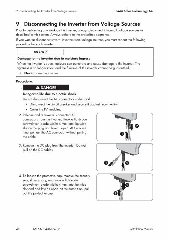
2. Release and remove all connected ACconnectors from the inverter. Hook a flat-bladescrewdriver (blade width: 4 mm) into the wideslot on the plug and lever it open. At the sametime, pull out the AC connector without pullingthe cable.
3. Remove the DC plug from the inverter. Do notpull on the DC cables.
4. To loosen the protective cap, remove the securityseal, if necessary, and hook a flat-bladescrewdriver (blade width: 4 mm) into the wideslot and and lever it open. At the same time, pullout the protective cap.
9 Disconnecting the Inverter from Voltage Sources SMA Solar Technology AG
Installation ManualSMA-SB240-IA-en-1248
5.
Risk of electric shock due to high voltages• Before carrying out any of the following work, wait five minutes for the capacitors todischarge.
9 Disconnecting the Inverter from Voltage SourcesSMA Solar Technology AG
Installation Manual 49SMA-SB240-IA-en-12
10 Disconnecting the Sunny Multigate from VoltageSources
Risk of electric shock due to contact with live components when opening theSunny MultigateThere are live components inside the Sunny Multigate. There is a risk of electric shock if you openthe Sunny Multigate.• Never open the Sunny Multigate.
Before working on the Sunny Multigate, always disconnect it from all voltage sources as describedin this section.
Procedure:1.
Danger to life due to electric shock• Disconnect the circuit breaker and secure it against reconnection.
2. Ensure that no voltage is present between the conductors L and N at the AC terminal Gridusing a suitable measuring device.
3. Ensure that no voltage is present between the conductor L and the grounding conductor at theAC terminal Grid using a suitable measuring device.
4. Ensure that no voltage is present between the conductors L and N at the AC terminal Inverterusing a suitable measuring device.
5. Ensure that no voltage is present between the conductor L and the grounding conductor at theAC terminal Inverter using a suitable measuring device.
10 Disconnecting the Sunny Multigate from Voltage Sources SMA Solar Technology AG
Installation ManualSMA-SB240-IA-en-1250
11 Troubleshooting
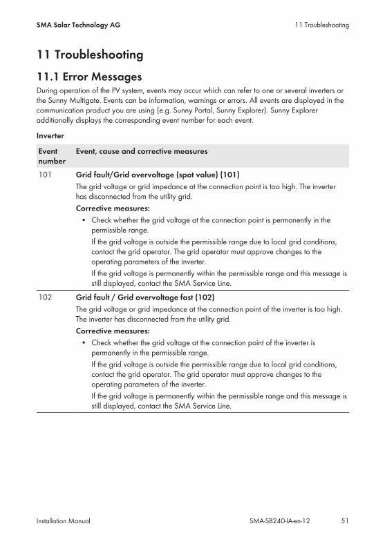
11.1 Error MessagesDuring operation of the PV system, events may occur which can refer to one or several inverters orthe Sunny Multigate. Events can be information, warnings or errors. All events are displayed in thecommunication product you are using (e.g. Sunny Portal, Sunny Explorer). Sunny Exploreradditionally displays the corresponding event number for each event.
Inverter
Eventnumber
Event, cause and corrective measures
101 Grid fault/Grid overvoltage (spot value) (101)The grid voltage or grid impedance at the connection point is too high. The inverterhas disconnected from the utility grid.Corrective measures:• Check whether the grid voltage at the connection point is permanently in thepermissible range.If the grid voltage is outside the permissible range due to local grid conditions,contact the grid operator. The grid operator must approve changes to theoperating parameters of the inverter.If the grid voltage is permanently within the permissible range and this message isstill displayed, contact the SMA Service Line.
102 Grid fault / Grid overvoltage fast (102)The grid voltage or grid impedance at the connection point of the inverter is too high.The inverter has disconnected from the utility grid.Corrective measures:• Check whether the grid voltage at the connection point of the inverter ispermanently in the permissible range.If the grid voltage is outside the permissible range due to local grid conditions,contact the grid operator. The grid operator must approve changes to theoperating parameters of the inverter.If the grid voltage is permanently within the permissible range and this message isstill displayed, contact the SMA Service Line.
11 TroubleshootingSMA Solar Technology AG
Installation Manual 51SMA-SB240-IA-en-12
Eventnumber
Event, cause and corrective measures
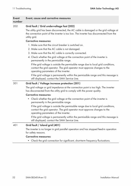
202 Grid fault / Grid undervoltage fast (202)The utility grid has been disconnected, the AC cable is damaged or the grid voltage atthe connection point of the inverter is too low. The inverter has disconnected from theutility grid.Corrective measures:1. Make sure that the circuit breaker is switched on.2. Make sure that the AC cable is not damaged.3. Make sure that the AC cable is correctly connected.4. Check whether the grid voltage at the connection point of the inverter ispermanently in the permissible range.If the grid voltage is outside the permissible range due to local grid conditions,contact the grid operator. The grid operator must approve changes to theoperating parameters of the inverter.If the grid voltage is permanently within the permissible range and this message isstill displayed, contact the SMA Service Line.
301 Grid fault / Voltage increase protection (301)The grid voltage or grid impedance at the connection point is too high. The inverterhas disconnected from the utility grid to comply with the power quality.Corrective measures:• Check whether the grid voltage at the connection point of the inverter ispermanently in the permissible range.If the grid voltage is outside the permissible range due to local grid conditions,contact the grid operator. The grid operator must approve changes to theoperating parameters of the inverter.If the grid voltage is permanently within the permissible range and this message isstill displayed, contact the SMA Service Line.
401 Grid fault / Island grid (401)The inverter is no longer in grid parallel operation and has stopped feed-in operationfor safety reasons.Corrective measures:• Check the grid connection for significant, short-term frequency fluctuations.
11 Troubleshooting SMA Solar Technology AG
Installation ManualSMA-SB240-IA-en-1252
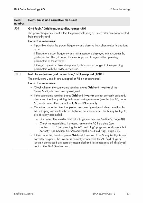
Eventnumber
Event, cause and corrective measures
501 Grid fault / Grid frequency disturbance (501)The power frequency is not within the permissible range. The inverter has disconnectedfrom the utility grid.Corrective measures:• If possible, check the power frequency and observe how often major fluctuationsoccur.If fluctuations occur frequently and this message is displayed often, contact thegrid operator. The grid operator must approve changes to the operatingparameters of the inverter.If the grid operator gives his approval, discuss any changes to the operatingparameters with the SMA Service Line.
1001 Installation failure grid connection / L/N swapped (1001)The conductors L and N are swapped or PE is not connected.Corrective measures:• Check whether the connecting terminal plates Grid and Inverter of theSunny Multigate are correctly assigned.
• If the connecting terminal plates Grid and Inverter are not correctly assigned,disconnect the Sunny Multigate from all voltage sources (see Section 10, page50) and connect the conductors L, N and PE correctly.
• Once the connecting terminal plates are correctly assigned, check whether theAC field plugs or junction boxes between the inverters and the Sunny Multigateare correctly assembled.– Disconnect the inverter from all voltage sources (see Section 9, page 48).– Check the assembling. If present, remove the AC field plug (seeSection 13.1 "Disconnecting the AC Field Plug", page 64) and assemble itcorrectly (see Section 6.4 "Assembling the AC Field Plug", page 33).
• If the connecting terminal plates Grid and Inverter of the Sunny Multigate arecorrectly assigned, the inverter is correctly connected, the AC field plugs orjunction boxes used are correctly assembled and this message is still displayed,contact the SMA Service Line.
11 TroubleshootingSMA Solar Technology AG
Installation Manual 53SMA-SB240-IA-en-12
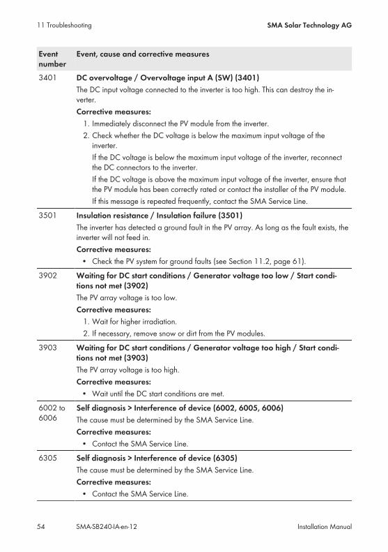
Eventnumber
Event, cause and corrective measures
3401 DC overvoltage / Overvoltage input A (SW) (3401)The DC input voltage connected to the inverter is too high. This can destroy the in-verter.Corrective measures:1. Immediately disconnect the PV module from the inverter.2. Check whether the DC voltage is below the maximum input voltage of theinverter.If the DC voltage is below the maximum input voltage of the inverter, reconnectthe DC connectors to the inverter.If the DC voltage is above the maximum input voltage of the inverter, ensure thatthe PV module has been correctly rated or contact the installer of the PV module.If this message is repeated frequently, contact the SMA Service Line.
3501 Insulation resistance / Insulation failure (3501)The inverter has detected a ground fault in the PV array. As long as the fault exists, theinverter will not feed in.Corrective measures:• Check the PV system for ground faults (see Section 11.2, page 61).
3902 Waiting for DC start conditions / Generator voltage too low / Start condi-tions not met (3902)The PV array voltage is too low.Corrective measures:1. Wait for higher irradiation.2. If necessary, remove snow or dirt from the PV modules.
3903 Waiting for DC start conditions / Generator voltage too high / Start condi-tions not met (3903)The PV array voltage is too high.Corrective measures:• Wait until the DC start conditions are met.
6002 to6006
Self diagnosis > Interference of device (6002, 6005, 6006)The cause must be determined by the SMA Service Line.Corrective measures:• Contact the SMA Service Line.
6305 Self diagnosis > Interference of device (6305)The cause must be determined by the SMA Service Line.Corrective measures:• Contact the SMA Service Line.
11 Troubleshooting SMA Solar Technology AG
Installation ManualSMA-SB240-IA-en-1254

Eventnumber
Event, cause and corrective measures
6402 Self diagnosis / Overtemperature (6402)The cause must be determined by the SMA Service Line.Corrective measures:• Contact the SMA Service Line.
6406 DC overcurrent / Overcurrent input A (HW) (6406)The current at the module input of the inverter is too high. The inverter has interruptedthe feed-in operation.Corrective measures:• Check whether the grid voltage at the connection point of the inverter ispermanently in the permissible range and/or whether voltage jumps occur (e.g.by switching on and off large loads).If voltage jumps occur or the grid voltage is outside the permissible range due tolocal grid conditions, contact the grid operator. The grid operator must approvechanges to the operating parameters of the inverter.If the grid voltage is permanently within the permissible range and this message isstill displayed, contact the SMA Service Line.
6415 Self diagnosis > Interference of device (6305)The cause must be determined by the SMA Service Line.Corrective measures:• Contact the SMA Service Line.
11 TroubleshootingSMA Solar Technology AG
Installation Manual 55SMA-SB240-IA-en-12
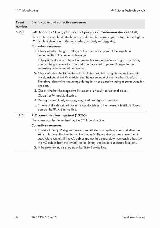
Eventnumber
Event, cause and corrective measures
6450 Self diagnosis / Energy transfer not possible / Interference device (6450)The inverter cannot feed into the utility grid. Possible causes: grid voltage is too high; aPV module is defective, soiled or shaded; a cloudy or foggy day.Corrective measures:1. Check whether the grid voltage at the connection point of the inverter ispermanently in the permissible range.If the grid voltage is outside the permissible range due to local grid conditions,contact the grid operator. The grid operator must approve changes to theoperating parameters of the inverter.
2. Check whether the DC voltage is stable in a realistic range in accordance withthe datasheet of the PV module and the assessment of the weather situation.Therefore, determine the voltage during inverter operation using a communicationproduct.
3. Check whether the respective PV module is heavily soiled or shaded.Clean the PV module if soiled.
4. During a very cloudy or foggy day, wait for higher irradiation.5. If none of the described causes is applicable and the message is still displayed,contact the SMA Service Line.
10265 PLC communication impaired (10265)The cause must be determined by the SMA Service Line.Corrective measures:1. If several Sunny Multigate devices are installed in a system, check whether theAC cables from the inverters to the Sunny Multigate devices have been laid inseparate channels. If the AC cables are not laid separately from each other, laythe AC cables from the inverter to the Sunny Multigate in separate locations.
2. If the problem persists, contact the SMA Service Line.
11 Troubleshooting SMA Solar Technology AG
Installation ManualSMA-SB240-IA-en-1256
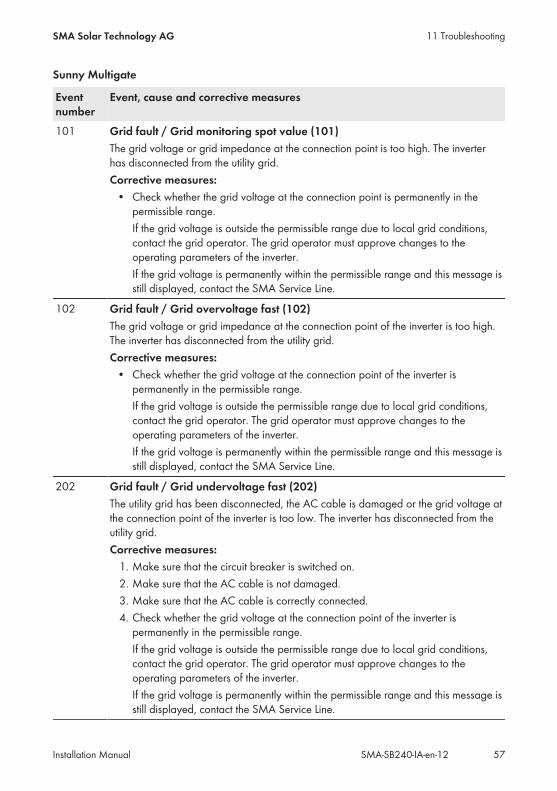
Sunny Multigate
Eventnumber
Event, cause and corrective measures
101 Grid fault / Grid monitoring spot value (101)The grid voltage or grid impedance at the connection point is too high. The inverterhas disconnected from the utility grid.Corrective measures:• Check whether the grid voltage at the connection point is permanently in thepermissible range.If the grid voltage is outside the permissible range due to local grid conditions,contact the grid operator. The grid operator must approve changes to theoperating parameters of the inverter.If the grid voltage is permanently within the permissible range and this message isstill displayed, contact the SMA Service Line.
102 Grid fault / Grid overvoltage fast (102)The grid voltage or grid impedance at the connection point of the inverter is too high.The inverter has disconnected from the utility grid.Corrective measures:• Check whether the grid voltage at the connection point of the inverter ispermanently in the permissible range.If the grid voltage is outside the permissible range due to local grid conditions,contact the grid operator. The grid operator must approve changes to theoperating parameters of the inverter.If the grid voltage is permanently within the permissible range and this message isstill displayed, contact the SMA Service Line.
202 Grid fault / Grid undervoltage fast (202)The utility grid has been disconnected, the AC cable is damaged or the grid voltage atthe connection point of the inverter is too low. The inverter has disconnected from theutility grid.Corrective measures:1. Make sure that the circuit breaker is switched on.2. Make sure that the AC cable is not damaged.3. Make sure that the AC cable is correctly connected.4. Check whether the grid voltage at the connection point of the inverter ispermanently in the permissible range.If the grid voltage is outside the permissible range due to local grid conditions,contact the grid operator. The grid operator must approve changes to theoperating parameters of the inverter.If the grid voltage is permanently within the permissible range and this message isstill displayed, contact the SMA Service Line.
11 TroubleshootingSMA Solar Technology AG
Installation Manual 57SMA-SB240-IA-en-12
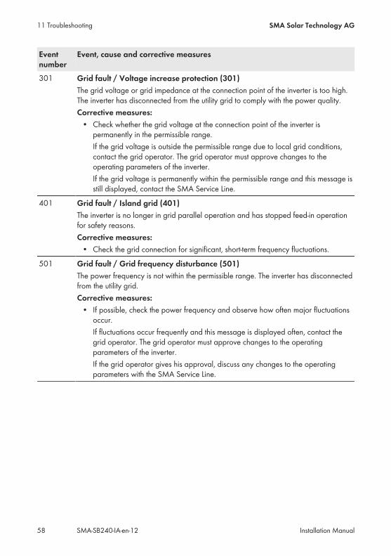
Eventnumber
Event, cause and corrective measures
301 Grid fault / Voltage increase protection (301)The grid voltage or grid impedance at the connection point of the inverter is too high.The inverter has disconnected from the utility grid to comply with the power quality.Corrective measures:• Check whether the grid voltage at the connection point of the inverter ispermanently in the permissible range.If the grid voltage is outside the permissible range due to local grid conditions,contact the grid operator. The grid operator must approve changes to theoperating parameters of the inverter.If the grid voltage is permanently within the permissible range and this message isstill displayed, contact the SMA Service Line.
401 Grid fault / Island grid (401)The inverter is no longer in grid parallel operation and has stopped feed-in operationfor safety reasons.Corrective measures:• Check the grid connection for significant, short-term frequency fluctuations.
501 Grid fault / Grid frequency disturbance (501)The power frequency is not within the permissible range. The inverter has disconnectedfrom the utility grid.Corrective measures:• If possible, check the power frequency and observe how often major fluctuationsoccur.If fluctuations occur frequently and this message is displayed often, contact thegrid operator. The grid operator must approve changes to the operatingparameters of the inverter.If the grid operator gives his approval, discuss any changes to the operatingparameters with the SMA Service Line.
11 Troubleshooting SMA Solar Technology AG
Installation ManualSMA-SB240-IA-en-1258
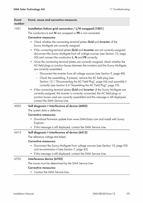
Eventnumber
Event, cause and corrective measures
1001 Installation failure grid connection / L/N swapped (1001)The conductors L and N are swapped or PE is not connected.Corrective measures:• Check whether the connecting terminal plates Grid and Inverter of theSunny Multigate are correctly assigned.
• If the connecting terminal plates Grid and Inverter are not correctly assigned,disconnect the Sunny Multigate from all voltage sources (see Section 10, page50) and connect the conductors L, N and PE correctly.
• Once the connecting terminal plates are correctly assigned, check whether theAC field plugs or junction boxes between the inverters and the Sunny Multigateare correctly assembled.– Disconnect the inverter from all voltage sources (see Section 9, page 48).– Check the assembling. If present, remove the AC field plug (seeSection 13.1 "Disconnecting the AC Field Plug", page 64) and assemble itcorrectly (see Section 6.4 "Assembling the AC Field Plug", page 33).
• If the connecting terminal plates Grid and Inverter of the Sunny Multigate arecorrectly assigned, the inverter is correctly connected, the AC field plugs orjunction boxes used are correctly assembled and this message is still displayed,contact the SMA Service Line.
6002 Self diagnosis > Interference of device (6002)The system data is defective.Corrective measures:• Download firmware update from www.SMA-Solar.com and install with SunnyExplorer.
• If this message is still displayed, contact the SMA Service Line.
6415 Self diagnosis > Interference of device (6415)The reference voltage test failed.Corrective measures:• Disconnect the Sunny Multigate from voltage sources (see Section 10, page 50)and re-commission it (see Section 7, page 42).
• If this message is still displayed, contact the SMA Service Line.
6702 Interference device (6702)The cause must be determined by the SMA Service Line.Corrective measures:• Contact the SMA Service Line.
11 TroubleshootingSMA Solar Technology AG
Installation Manual 59SMA-SB240-IA-en-12
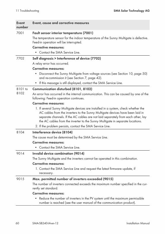
Eventnumber
Event, cause and corrective measures
7001 Fault sensor interior temperature (7001)The temperature sensor for the indoor temperature of the Sunny Multigate is defective.Feed-in operation will be interrupted.Corrective measures:• Contact the SMA Service Line.
7702 Self diagnosis > Interference of device (7702)A relay error has occurred.Corrective measures:• Disconnect the Sunny Multigate from voltage sources (see Section 10, page 50)and re-commission it (see Section 7, page 42).
• If this message is still displayed, contact the SMA Service Line.
8101 to8102
Communication disturbed (8101, 8102)An error has occurred in the internal communication. This can be caused by one of thefollowing: Feed-in operation continues.Corrective measures:1. If several Sunny Multigate devices are installed in a system, check whether theAC cables from the inverters to the Sunny Multigate devices have been laid inseparate channels. If the AC cables are not laid separately from each other, laythe AC cables from the inverter to the Sunny Multigate in separate locations.
2. If the problem persists, contact the SMA Service Line.
8104 Interference device (8104)The cause must be determined by the SMA Service Line.Corrective measures:• Contact the SMA Service Line.
9014 Invalid device combination (9014)The Sunny Multigate and the inverters cannot be operated in this combination.Corrective measures:1. Contact the SMA Service Line and request the latest firmware update, ifnecessary.
9015 Max. permitted number of inverters exceeded (9015)The number of inverters connected exceeds the maximum number specified in the cur-rently set standard.Corrective measures:• Reduce the number of inverters in the PV system until the maximum permissiblenumber is reached (see the user manual of the communication product).
11 Troubleshooting SMA Solar Technology AG
Installation ManualSMA-SB240-IA-en-1260
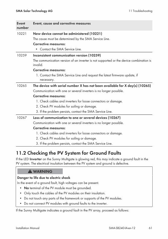
Eventnumber
Event, cause and corrective measures
10221 New device cannot be administered (10221)The cause must be determined by the SMA Service Line.Corrective measures:• Contact the SMA Service Line.
10259 Inconsistent communication version (10259)The communication version of an inverter is not supported or the device combination isinvalid.Corrective measures:1. Contact the SMA Service Line and request the latest firmware update, ifnecessary.
10265 The device with serial number X has not been available for X day(s) (10265)Communication with one or several inverters is no longer possible.Corrective measures:1. Check cables and inverters for loose connectors or damage.2. Check PV modules for soiling or damage.3. If the problem persists, contact the SMA Service Line.
10267 Loss of communication to one or several devices (10267)Communication with one or several inverters is no longer possible.Corrective measures:1. Check cables and inverters for loose connectors or damage.2. Check PV modules for soiling or damage.3. If the problem persists, contact the SMA Service Line.
11.2 Checking the PV System for Ground FaultsIf the LED Inverter on the Sunny Multigate is glowing red, this may indicate a ground fault in thePV system. The electrical insulation between the PV system and ground is defective.
Danger to life due to electric shockIn the event of a ground fault, high voltages can be present.• No terminal of the PV module must be grounded.• Only touch the cables of the PV modules on their insulation.• Do not touch any parts of the framework or supports of the PV modules.• Do not connect PV modules with ground faults to the inverter.
If the Sunny Multigate indicates a ground fault in the PV array, proceed as follows:
11 TroubleshootingSMA Solar Technology AG
Installation Manual 61SMA-SB240-IA-en-12
Procedure:1. Make sure that no terminal of the PV module is grounded.2. Use Sunny Portal or Sunny Explorer to determine which of the connected inverters has aground fault (see user manual of the communication product at www.SMA-Solar.com).
3.
Risk of electric shock due to high voltages• Disconnect the affected inverter from all voltage sources (see Section 9, page 48).
4. Measure voltages with a suitable measuring device.• Measure the voltages between the positive terminal and the ground potential.• Measure the voltages between the negative terminal and the ground potential.• Measure the voltages between the positive and negative terminals.If the following results are present at the same time, there is a ground fault in the PVsystem:– All measured voltages are stable.– The sum of the two voltages to ground potential is approximately equal to thevoltage between the positive and negative terminals.
5. In case of a ground fault, solve the problem and recommission the inverter (see Section 12,page 63).
6. If there is no ground fault and the error persists, contact the SMA Service Line.
11 Troubleshooting SMA Solar Technology AG
Installation ManualSMA-SB240-IA-en-1262
12 Recommissioning the InverterRequirements:☐ All inverters must be correctly mounted.☐ The PV modules must be correctly mounted.☐ The circuit breaker must be correctly rated.☐ The Sunny Multigate must be correctly installed in the industrial enclosure.☐ The unused AC pin connector on the last inverter of the PV system must be sealed with aprotective cap.
☐ The AC cable of the utility grid must be correctly connected to the Sunny Multigate. Allconductors must be connected in accordance with the terminal labels. No conductors must beswapped.
Procedure:1. Connect the AC cables to the inverters (see Section 6.3 "AC Cabling of the Inverters", page 31).
2. Connect the first inverter to the Sunny Multigate (see Section 6.6 "Connecting the First Inverterto the Sunny Multigate", page 36). All conductors must be connected in accordance with theterminal labels. No conductors must be swapped.
3. Connect the PV modules to the inverters (see Section 6.8 "Connecting the PV Modules to theInverters", page 40).
4. Remove the cover of the PV modules.5. Switch on the two-pole circuit breaker.☑ Both LEDs on the Sunny Multigate are glowing green. Feed-in operation begins.✖ The LED Inverter is off?There is a disturbance in the PV system.• Eliminate the disturbance (see Section 11 "Troubleshooting", page 51). You will findthe detailed error message in Sunny Portal or Sunny Explorer.
✖ The LED Inverter on the Sunny Multigate is glowing orange or red?There is a disturbance in at least one of the connected inverters.• Eliminate the disturbance (see Section 11 "Troubleshooting", page 51). You will findthe detailed error message in Sunny Portal or Sunny Explorer.
✖ The LED Multigate on the Sunny Multigate is glowing orange or red?There is a disturbance in the Sunny Multigate.• Eliminate the disturbance (see Section 4.3 "LED Signals", page 16).
12 Recommissioning the InverterSMA Solar Technology AG
Installation Manual 63SMA-SB240-IA-en-12
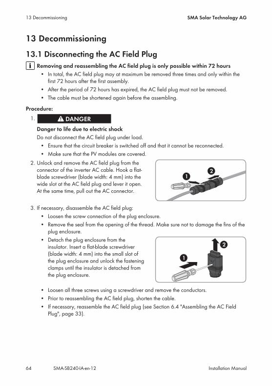
13 Decommissioning
13.1 Disconnecting the AC Field PlugRemoving and reassembling the AC field plug is only possible within 72 hours• In total, the AC field plug may at maximum be removed three times and only within thefirst 72 hours after the first assembly.
• After the period of 72 hours has expired, the AC field plug must not be removed.• The cable must be shortened again before the assembling.
Procedure:1.
Danger to life due to electric shockDo not disconnect the AC field plug under load.• Ensure that the circuit breaker is switched off and that it cannot be reconnected.• Make sure that the PV modules are covered.
2. Unlock and remove the AC field plug from theconnector of the inverter AC cable. Hook a flat-blade screwdriver (blade width: 4 mm) into thewide slot at the AC field plug and lever it open.At the same time, pull out the AC connector.
3. If necessary, disassemble the AC field plug:• Loosen the screw connection of the plug enclosure.• Remove the seal from the opening of the thread. Make sure not to damage the fins of theplug enclosure.
• Detach the plug enclosure from theinsulator. Insert a flat-blade screwdriver(blade width: 4 mm) into the small slot ofthe plug enclosure and unlock the fasteningclamps until the insulator is detached fromthe plug enclosure.
• Loosen all three screws using a screwdriver and remove the conductors.• Prior to reassembling the AC field plug, shorten the cable.• If necessary, reassemble the AC field plug (see Section 6.4 "Assembling the AC FieldPlug", page 33).
13 Decommissioning SMA Solar Technology AG
Installation ManualSMA-SB240-IA-en-1264
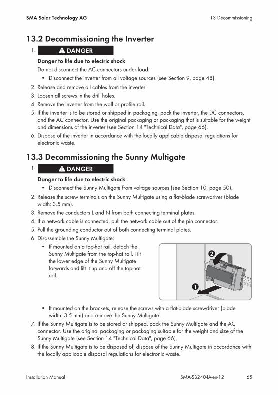
13.2 Decommissioning the Inverter1.
Danger to life due to electric shockDo not disconnect the AC connectors under load.• Disconnect the inverter from all voltage sources (see Section 9, page 48).
2. Release and remove all cables from the inverter.3. Loosen all screws in the drill holes.4. Remove the inverter from the wall or profile rail.5. If the inverter is to be stored or shipped in packaging, pack the inverter, the DC connectors,and the AC connector. Use the original packaging or packaging that is suitable for the weightand dimensions of the inverter (see Section 14 "Technical Data", page 66).
6. Dispose of the inverter in accordance with the locally applicable disposal regulations forelectronic waste.
13.3 Decommissioning the Sunny Multigate1.
Danger to life due to electric shock• Disconnect the Sunny Multigate from voltage sources (see Section 10, page 50).
2. Release the screw terminals on the Sunny Multigate using a flat-blade screwdriver (bladewidth: 3.5 mm).
3. Remove the conductors L and N from both connecting terminal plates.4. If a network cable is connected, pull the network cable out of the pin connector.5. Pull the grounding conductor out of both connecting terminal plates.6. Disassemble the Sunny Multigate:• If mounted on a top-hat rail, detach theSunny Multigate from the top-hat rail. Tiltthe lower edge of the Sunny Multigateforwards and lift it up and off the top-hatrail.
• If mounted on the brackets, release the screws with a flat-blade screwdriver (bladewidth: 3.5 mm) and remove the Sunny Multigate.
7. If the Sunny Multigate is to be stored or shipped, pack the Sunny Multigate and the ACconnector. Use the original packaging or packaging suitable for the weight and size of theSunny Multigate (see Section 14 "Technical Data", page 66).
8. If the Sunny Multigate is to be disposed of, dispose of the Sunny Multigate in accordance withthe locally applicable disposal regulations for electronic waste.
13 DecommissioningSMA Solar Technology AG
Installation Manual 65SMA-SB240-IA-en-12

14 Technical Data
14.1 Requirements for the PV ModulesMaximum DC power at standard test condition-s (STC)
300 W
MPP voltage range at standard test condition-s (STC)
26 V to 32 V
Maximum short-circuit current at standard testconditions (STC)
12 A
14.2 Sunny Boy 240DC Input
Maximum number of connected PV modules perinverter
1
Maximum input voltage 45 V
MPP voltage range at 230 V 23.0 V to 39.0 V
Rated input voltage 29.5 V
Minimum input voltage 23.0 V
Minimum initial input voltage 23.0 V
Maximum initial input voltage 40 V
Maximum input current 8.5 A
Maximum short-circuit current per module* 12 A
Overvoltage category as per IEC 60664-1 II* In accordance with IEC 62109-2: ISC PV
AC Output
Rated power at 230 V, 50 Hz 230 W
Maximum apparent AC power 230 VA
Rated grid voltage 230 V
Nominal AC voltage 220 V / 230 V / 240 V
AC voltage range 184 V to 270 V
Nominal AC current at 220 V 1 A
Nominal AC current at 230 V 1 A
Nominal AC current at 240 V 0.96 A
14 Technical Data SMA Solar Technology AG
Installation ManualSMA-SB240-IA-en-1266
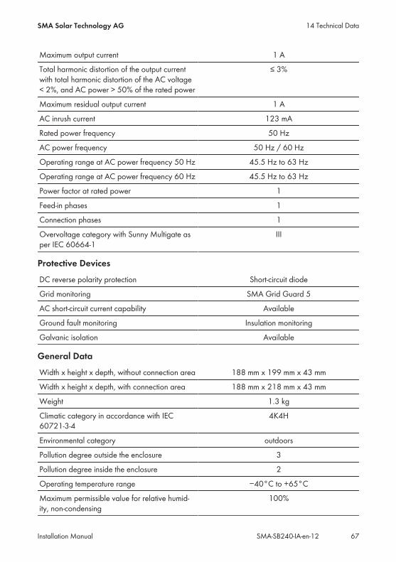
Maximum output current 1 A
Total harmonic distortion of the output currentwith total harmonic distortion of the AC voltage< 2%, and AC power > 50% of the rated power
≤ 3%
Maximum residual output current 1 A
AC inrush current 123 mA
Rated power frequency 50 Hz
AC power frequency 50 Hz / 60 Hz
Operating range at AC power frequency 50 Hz 45.5 Hz to 63 Hz
Operating range at AC power frequency 60 Hz 45.5 Hz to 63 Hz
Power factor at rated power 1
Feed-in phases 1
Connection phases 1
Overvoltage category with Sunny Multigate asper IEC 60664‑1
III
Protective Devices
DC reverse polarity protection Short-circuit diode
Grid monitoring SMA Grid Guard 5
AC short-circuit current capability Available
Ground fault monitoring Insulation monitoring
Galvanic isolation Available
General Data
Width x height x depth, without connection area 188 mm x 199 mm x 43 mm
Width x height x depth, with connection area 188 mm x 218 mm x 43 mm
Weight 1.3 kg
Climatic category in accordance with IEC60721-3-4
4K4H
Environmental category outdoors
Pollution degree outside the enclosure 3
Pollution degree inside the enclosure 2
Operating temperature range −40°C to +65°C
Maximum permissible value for relative humid-ity, non-condensing
100%
14 Technical DataSMA Solar Technology AG
Installation Manual 67SMA-SB240-IA-en-12

Maximum operating altitude above mean sealevel
3,000 m
Noise emission, typical ≤ 38 dB(A)
Power loss in night mode < 0.03 W
Topology HF transformer
Cooling method Convection
Degree of protection for electronics in accor-dance with IEC 60529
IP65
Protection class in accordance with IEC 61140 I
Grid configurations TN-C grid configuration, TN-S gridconfiguration, TN-C-S grid configuration, Delta-IT
*
Approvals and national standardsAs of June 2014**
VDE0126-1-1, VDE-AR-N-4105, VFR2014, PPC,EN 50438-CZ, NEN-EN 50438, EN 50438,C10/11/2012, AS 4777.3, RD1699, G83/2,
CEI0-21, IEC 62109-2* Delta-IT: When using in these networks, the grounding conductor monitoring must be deactivated andan additional grounding connected to the inverter.
** IEC 62109-2: This standard requires that the PV system is connected to Sunny Portal and that the faultalert is activated in Sunny Portal.
Climatic Conditions
As per IEC 60721-3-4, installation type C, class 4K4H
Extended temperature range −40°C to +65°C
Extended humidity range 0% to 100%
Extended air pressure range 79.5 kPa to 106 kPa
As per IEC 60721-3-4, transport type E, class 2K3
Temperature range −25°C to +70°C
Features
DC Connection DC plug with DC connector*:DC plug, assembled, MC4DC plug, assembled, Tyco
14 Technical Data SMA Solar Technology AG
Installation ManualSMA-SB240-IA-en-1268
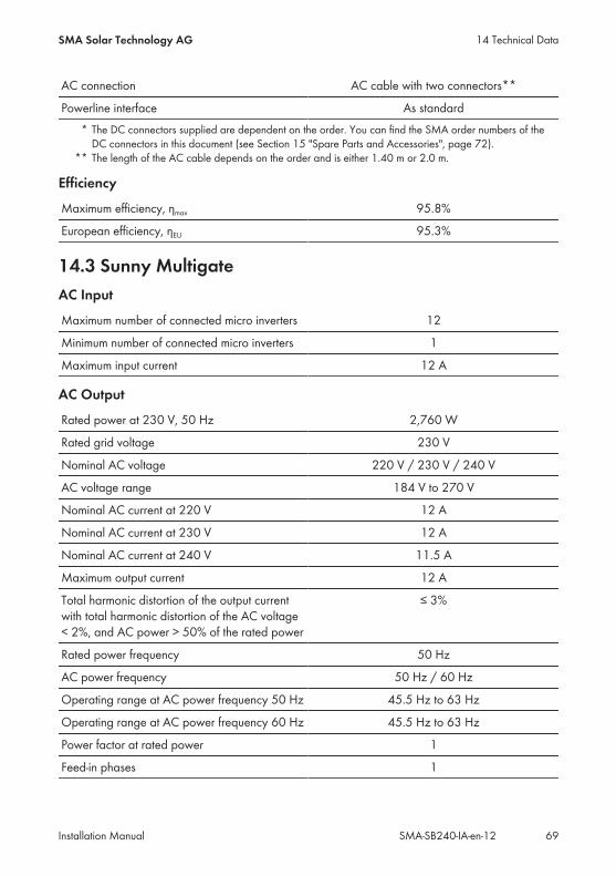
AC connection AC cable with two connectors**
Powerline interface As standard* The DC connectors supplied are dependent on the order. You can find the SMA order numbers of theDC connectors in this document (see Section 15 "Spare Parts and Accessories", page 72).
** The length of the AC cable depends on the order and is either 1.40 m or 2.0 m.
Efficiency
Maximum efficiency, ηmax 95.8%
European efficiency, ηEU 95.3%
14.3 Sunny MultigateAC Input
Maximum number of connected micro inverters 12
Minimum number of connected micro inverters 1
Maximum input current 12 A
AC Output
Rated power at 230 V, 50 Hz 2,760 W
Rated grid voltage 230 V
Nominal AC voltage 220 V / 230 V / 240 V
AC voltage range 184 V to 270 V
Nominal AC current at 220 V 12 A
Nominal AC current at 230 V 12 A
Nominal AC current at 240 V 11.5 A
Maximum output current 12 A
Total harmonic distortion of the output currentwith total harmonic distortion of the AC voltage< 2%, and AC power > 50% of the rated power
≤ 3%
Rated power frequency 50 Hz
AC power frequency 50 Hz / 60 Hz
Operating range at AC power frequency 50 Hz 45.5 Hz to 63 Hz
Operating range at AC power frequency 60 Hz 45.5 Hz to 63 Hz
Power factor at rated power 1
Feed-in phases 1
14 Technical DataSMA Solar Technology AG
Installation Manual 69SMA-SB240-IA-en-12

Connection phases 1
Overvoltage category as per IEC 60664-1 III
Protective Devices
Overvoltage protection Varistors
Maximum permissible fuse protection 16 A
General Data
Width x height x depth, without connection area 162 mm x 90 mm x 68 mm
Weight 0.75 kg
Climatic category in accordance with IEC60721-3-4
4K1
Environmental category Not air-conditioned, indoors
Pollution degree outside the enclosure 3
Pollution degree inside the enclosure 2
Operating temperature range −40°C to +45°C
Maximum permissible value for relative humid-ity, non-condensing
100%
Maximum operating altitude above mean sealevel
3,000 m
Cooling method Convection
Degree of protection for electronics in accor-dance with IEC 60529
IP20
Protection class in accordance with IEC 61140 I
Grid configurations TN-C grid configuration, TN-S gridconfiguration, TN-C-S grid configuration, Delta-IT
*
Approvals and national standards As of June 2014
VDE0126-1-1, VDE-AR-N-4105, VFR2014, PPC,EN 50438-CZ, NEN-EN 50438, EN 50438,C10/11/2012, AS 4777.3, RD1699, G83/2,
CEI0-21, IEC 62109-2*** Delta-IT: When using in these networks, the grounding conductor monitoring must be deactivated andan additional grounding connected to the inverter.
** IEC 62109-2: This standard requires that the PV system is connected to Sunny Portal and that the faultalert is activated in Sunny Portal.
14 Technical Data SMA Solar Technology AG
Installation ManualSMA-SB240-IA-en-1270
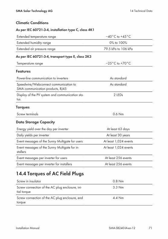
Climatic Conditions
As per IEC 60721-3-4, installation type C, class 4K1
Extended temperature range −40°C to +45°C
Extended humidity range 0% to 100%
Extended air pressure range 79.5 kPa to 106 kPa
As per IEC 60721-3-4, transport type E, class 2K3
Temperature range −25°C to +70°C
Features
Power-line communication to inverters As standard
Speedwire/Webconnect communication toSMA communication products, RJ45
As standard
Display of the PV system and communication sta-tus
2 LEDs
Torques
Screw terminals 0.6 Nm
Data Storage Capacity
Energy yield over the day per inverter At least 63 days
Daily yields per inverter At least 30 years
Event messages of the Sunny Multigate for users At least 1,024 events
Event messages of the Sunny Multigate for in-stallers
At least 1,024 events
Event messages per inverter for users At least 256 events
Event messages per inverter for installers At least 256 events
14.4 Torques of AC Field PlugsScrew in insulator 0.8 Nm
Screw connection of the AC plug enclosure, ini-tial torque
3.3 Nm
Screw connection of the AC plug enclosure, endtorque
4.4 Nm
14 Technical DataSMA Solar Technology AG
Installation Manual 71SMA-SB240-IA-en-12

15 Spare Parts and AccessoriesYou will find the corresponding accessories and spare parts for your product in the followingoverview. If required, these can be ordered from SMA Solar Technology AG or your distributor.
Designation Brief description SMA order numberDC plug, assembled,MC4
24 DC plugs, assembled, Multi-ContactKST4
MI-DCMC4-10
DC plug, assembled,Tyco
24 DC plugs assembled with Tyco Solar-lock
MI-DCTYCO-10
AC field plug 20 AC field plugs MI-ACCON-10
AC protective cap 200 AC protective caps MI-ACCAP-10
AC cable 1.40 m 24 AC cables with counterplugs for con-necting the inverters among each other
MI-ACCAB14-10
AC cable 2.0 m 24 AC cables with counterplugs for con-necting the inverters among each other
MI-ACCAB20-10
Bootlace ferrules2.5 mm²
Manufacturer: Miromar LLC Distributor: Ferrules DirectOrder no. N25010
Cable shears Insulated handles, 165 mmManufacturer: KNIPEX
via distributorArt. no. 95 16 165
Stripping knife withstraight knife blade
TiN 8 mm to 28 mmManufacturer: JOKARI
via distributorArt. no. 728000
Insulation stripping tool Cross-section up to 10 mm², insulation strip-ping length up to 25 mmManufacturer: WEIDMÜLLER
via distributorOrder no. 9005000000
Crimping tool Square crimping tool for bootlace ferrulesup to 10 mm²Manufacturer: RENNSTEIG
via distributorArt. no. 610 084 3
Torque screwdriver 1.4" hexagon socket, 0.3 Nm to 1.2 NmManufacturer: WERA
via distributorArt. no. 05074700001
Screwdriver bit 1.4" hexagon, length: 25 mmApplication: cross-head screwsManufacturer: WERA
via distributorArt. no. 05056422001
Torque wrench Adjustable by scale,Torque range: 2 Nm to 20 NmManufacturer: STAHLWILLE
via distributorArt. no. 50181002
Crow-Ring wrench, AF25
Manufacturer: STAHLWILLE via distributorArt. no. 02190025
15 Spare Parts and Accessories SMA Solar Technology AG
Installation ManualSMA-SB240-IA-en-1272
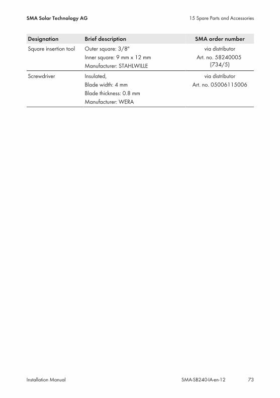
Designation Brief description SMA order numberSquare insertion tool Outer square: 3/8"
Inner square: 9 mm x 12 mmManufacturer: STAHLWILLE
via distributorArt. no. 58240005
(734/5)
Screwdriver Insulated,Blade width: 4 mmBlade thickness: 0.8 mmManufacturer: WERA
via distributorArt. no. 05006115006
15 Spare Parts and AccessoriesSMA Solar Technology AG
Installation Manual 73SMA-SB240-IA-en-12
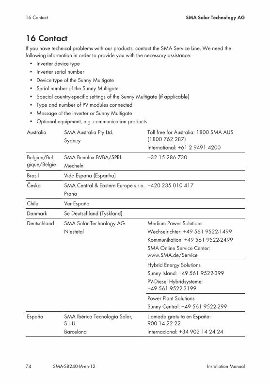
16 ContactIf you have technical problems with our products, contact the SMA Service Line. We need thefollowing information in order to provide you with the necessary assistance:• Inverter device type• Inverter serial number• Device type of the Sunny Multigate• Serial number of the Sunny Multigate• Special country-specific settings of the Sunny Multigate (if applicable)• Type and number of PV modules connected• Message of the inverter or Sunny Multigate• Optional equipment, e.g. communication products
Australia SMA Australia Pty Ltd.Sydney
Toll free for Australia: 1800 SMA AUS(1800 762 287)International: +61 2 9491 4200
Belgien/Bel-gique/België
SMA Benelux BVBA/SPRLMecheln
+32 15 286 730
Brasil Vide España (Espanha)
Česko SMA Central & Eastern Europe s.r.o.Praha
+420 235 010 417
Chile Ver España
Danmark Se Deutschland (Tyskland)
Deutschland SMA Solar Technology AGNiestetal
Medium Power SolutionsWechselrichter: +49 561 9522‑1499Kommunikation: +49 561 9522‑2499SMA Online Service Center:www.SMA.de/Service
Hybrid Energy SolutionsSunny Island: +49 561 9522-399PV-Diesel Hybridsysteme:+49 561 9522-3199
Power Plant SolutionsSunny Central: +49 561 9522-299
España SMA Ibérica Tecnología Solar,S.L.U.Barcelona
Llamada gratuita en España:900 14 22 22Internacional: +34 902 14 24 24
16 Contact SMA Solar Technology AG
Installation ManualSMA-SB240-IA-en-1274
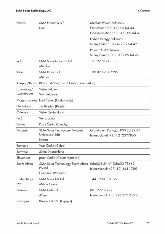
France SMA France S.A.S.Lyon
Medium Power SolutionsOnduleurs : +33 472 09 04 40Communication : +33 472 09 04 41
Hybrid Energy SolutionsSunny Island : +33 472 09 04 42
Power Plant SolutionsSunny Central : +33 472 09 04 43
India SMA Solar India Pvt. Ltd.Mumbai
+91 22 61713888
Italia SMA Italia S.r.l.Milano
+39 02 8934-7299
Κύπρος/Kıbrıs Βλέπε Ελλάδα/ Bkz. Ελλάδα (Yunanistan)
Luxemburg/Luxembourg
Siehe BelgienVoir Belgique
Magyarország lásd Česko (Csehország)
Nederland zie Belgien (België)
Österreich Siehe Deutschland
Perú Ver España
Polska Patrz Česko (Czechy)
Portugal SMA Solar Technology Portugal,Unipessoal LdaLisboa
Gratuito em Portugal: 800 20 89 87Internacional: +351 212377860
România Vezi Česko (Cehia)
Schweiz Siehe Deutschland
Slovensko pozri Česko (Česká republika)
South Africa SMA Solar Technology South AfricaPty Ltd.Centurion (Pretoria)
08600 SUNNY (08600 78669)International: +27 (12) 643 1785
United King-dom
SMA Solar UK Ltd.Milton Keynes
+44 1908 304899
Ελλάδα SMA Hellas AEΑθήνα
801 222 9 222International: +30 212 222 9 222
България Вижте Ελλάδα (Гърция)
16 ContactSMA Solar Technology AG
Installation Manual 75SMA-SB240-IA-en-12
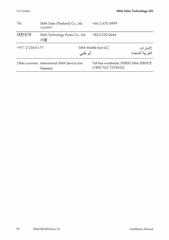
SMA Solar (Thailand) Co., Ltd. +66 2 670 6999
대한민국 SMA Technology Korea Co., Ltd.서울
+82-2-520-2666
+971 2 234-6177 SMA Middle East LLC
/01,234 9:; Middle East LLC
,2345%6!78%
9:;*<+%,='3)>+%
Other countries International SMA Service LineNiestetal
Toll free worldwide: 00800 SMA SERVICE(+800 762 7378423)
16 Contact SMA Solar Technology AG
Installation ManualSMA-SB240-IA-en-1276
17 EC Declaration of Conformitywithin the meaning of the EC directives• 2004/108/EG (Electromagnetic compatibility, EMC)• 2006/95/EG (Low voltage directive)SMA Solar Technology AG confirms herewith that the inverters described in this document are incompliance with the fundamental requirements and other relevant provisions of the above-mentioned directives. The entire EC Declaration of Conformity can be found at www.SMA-Solar.com.
17 EC Declaration of ConformitySMA Solar Technology AG
Installation Manual 77SMA-SB240-IA-en-12

SMA Solar Technology
www.SMA-Solar.com