Embed Size (px)
Citation preview
052561-001r4 Printed in USA March, 2017
INSTALLATION MANUAL PIONEER PATIO AWNING
MANUALLY OPERATED PATIO AWNINGRV
Read this manual before installing or using this product. Failure to follow the instructions and safety precautions in this manual can result in personal injury and/or cause the product to not operate properly.
TABLE OF CONTENTS Component Checklist.................................................................................................................... 1
Installation ..................................................................................................................................... 2 Installing an awning rail (if required) ....................................................................................................... 2 Assembling the Awning .......................................................................................................................... 2 Mounting the Bottom Mounting Brackets ................................................................................................ 3 Mounting the Awning .............................................................................................................................. 3
Installing the Stop Bolt .................................................................................................................... 4 Securing the Fabric ........................................................................................................................ 4 Installing the Rubber Bumpers ....................................................................................................... 4
Factory Installed LEDs (Optional) ................................................................................................ 5 White LED Schematic and Layout .......................................................................................................... 5 Harness Routing into the Vehicle ........................................................................................................... 5 Switch Installation6
PROPRIETARY STATEMENT The Pioneer Patio Awning is a product of Carefree of Colorado, located in Broomfield, Colorado, USA. The information contained in or disclosed in this document is considered proprietary to Carefree of Colorado. Every effort has been made to ensure that the information presented in the document is accurate and complete. However, Carefree of Colorado assumes no liability for errors or for any damages that result from the use of this document.
The information contained in this manual pertains to the current configuration of the models listed on the title page. Earlier model configurations may differ from the information given. Carefree of Colorado reserves the right to cancel, change, alter or add any parts and assemblies, described in this manual, without prior notice.
Carefree of Colorado agrees to allow the reproduction of this document for use with Carefree of Colorado products only. Any other reproduction or translation of this document in whole or part is strictly prohibited without prior written approval from Carefree of Colorado.
SAFETY INFORMATION
This is the safety alert symbol. It is used to alert individuals to potential personal injury hazards. Obey all safety messages that follow this symbol to avoid possible personal injury or death.
WARNING Indicates a hazardous situation, which if not avoided, could result in death or serious bodily injury.
CAUTION Indicates a hazardous situation, which if not avoided, may result in minor or moderate bodily injury.
NOTICE Indicates a situation that may result in equipment-related damage.
General Safety:
WARNING Shock Hazard. Always disconnect battery or power source before working on or around the electrical system.
WARNING Always wear appropriate safety equipment (i.e. goggles).
CAUTION Always use appropriate lifting devices and/or helpers when lifting or
holding heavy objects.
NOTICE When using fasteners, do not over tighten. Soft materials such as fiberglass, aluminum and wood can be "stripped out" and lose the ability to grip and hold.
CALIFORNIA PROPOSITION 65
WARNING This product contains chemicals known to the state of California to cause cancer or birth defects or other reproductive harm. California’s Proposition 65 requires this warning to be given to customers in the state of California.
Carefree of Colorado 2145 W. 6th Avenue Broomfield, CO 80020 a Scott Fetzer company
Carefree of Colorado Installation Manual PIONEER PATIO AWNING
052561-001r4 1
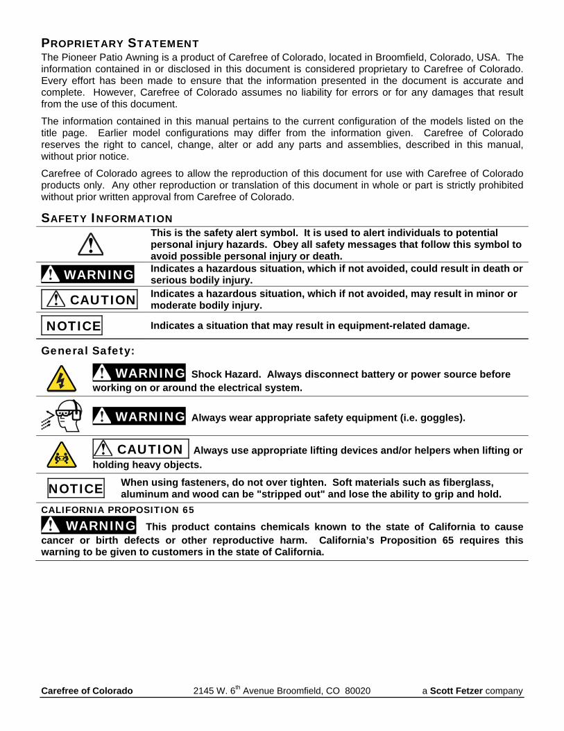
COMPONENT CHECKLIST
ITEM DESCRIPTION QTY NOTE
1a Roller Tube with Fabric 1 1b Roller Tube with Fabric and Uniguard 1 1 2 Idler End plug Assembly LH 1 3 Manual Crank End plug Assembly RH 1 4 Arm Assembly, LH Latch Lever 1 2 4 Arm Assembly, RH Latch Lever 1 2 5 Bottom Bracket 2 6 Lag Screw 1/4 x 3 4 7 Lag Screw 1/4 x 2 1/2 4 8 Screw, Square Drive 1/4-20 x 7/16 4 9 Screw, Truss Head Square Drive #10 x 5/8 5 10 Lock Washer 1/4 2 11 Spacer 2 12 Cap Nut 1/4-20 2 13 Screw, Hex Washer Head #6 x 3/8 2 14 Bumpers (set of two) 1 15 Hand Crank 1 16 Clip, Crank Handle 2 Notes: 1. Uniguard is optional and specified at time of order. Available only with select fabrics, refer to sales
literature for availability. 2. Arm assemblies are complete and include upper mounting bracket. 3. Tractioners and screws (item 3) are furnished with roller tube assemblies equipped with optional
Alumiguard or Uniguard.
976 8 121110 13
mc002
3
2
4R
5
14
4L
1a
1b
15
16
PIONEER PATIO AWNING Installation Manual Carefree of Colorado
2 0052561-001r4
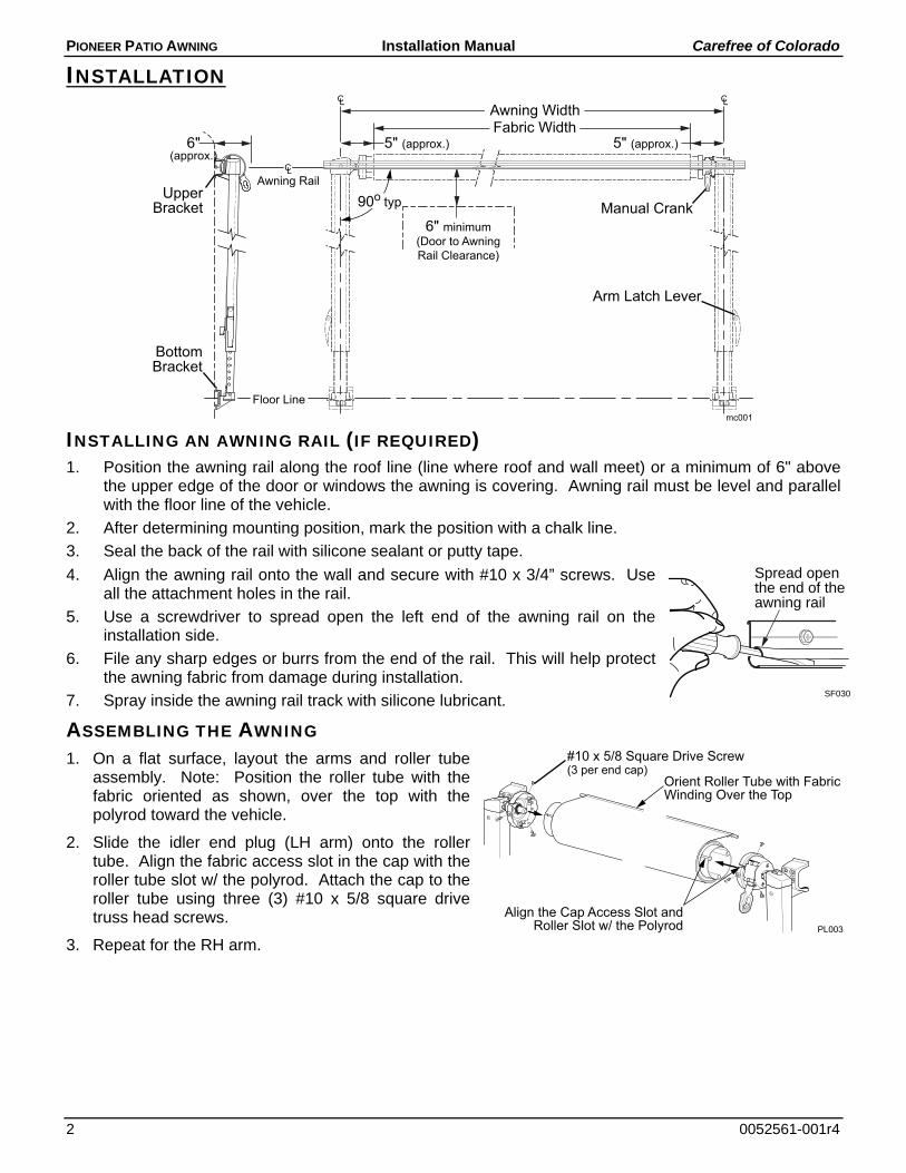
INSTALLATION
INSTALLING AN AWNING RAIL (IF REQUIRED) 1. Position the awning rail along the roof line (line where roof and wall meet) or a minimum of 6" above
the upper edge of the door or windows the awning is covering. Awning rail must be level and parallel with the floor line of the vehicle.
2. After determining mounting position, mark the position with a chalk line.
3. Seal the back of the rail with silicone sealant or putty tape.
4. Align the awning rail onto the wall and secure with #10 x 3/4” screws. Use all the attachment holes in the rail.
5. Use a screwdriver to spread open the left end of the awning rail on the installation side.
6. File any sharp edges or burrs from the end of the rail. This will help protect the awning fabric from damage during installation.
7. Spray inside the awning rail track with silicone lubricant.
ASSEMBLING THE AWNING 1. On a flat surface, layout the arms and roller tube
assembly. Note: Position the roller tube with the fabric oriented as shown, over the top with the polyrod toward the vehicle.
2. Slide the idler end plug (LH arm) onto the roller tube. Align the fabric access slot in the cap with the roller tube slot w/ the polyrod. Attach the cap to the roller tube using three (3) #10 x 5/8 square drive truss head screws.
3. Repeat for the RH arm.
Awning Rail
Floor Line
Awning Width
90o typ
mc001
Fabric Width5" (approx.)
BottomBracket
UpperBracket
6" minimum(Door to AwningRail Clearance)
5" (approx.)
Arm Latch Lever
Manual Crank
6"(approx.)
Spread openthe end of theawning rail
SF030
#10 x 5/8 Square Drive Screw(3 per end cap)
Align the Cap Access Slot and Roller Slot w/ the Polyrod
Orient Roller Tube with FabricWinding Over the Top
PL003
Carefree of Colorado Installation Manual PIONEER PATIO AWNING
052561-001r4 3
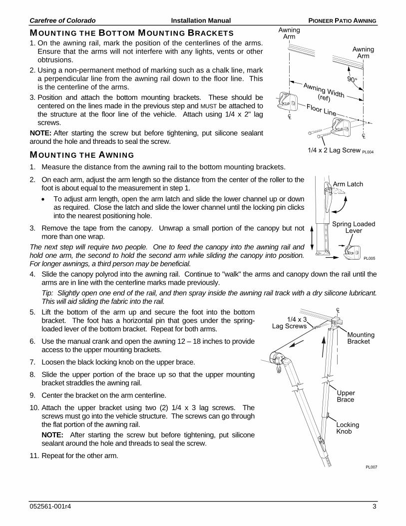
MOUNTING THE BOTTOM MOUNTING BRACKETS 1. On the awning rail, mark the position of the centerlines of the arms.
Ensure that the arms will not interfere with any lights, vents or other obtrusions.
2. Using a non-permanent method of marking such as a chalk line, mark a perpendicular line from the awning rail down to the floor line. This is the centerline of the arms.
3. Position and attach the bottom mounting brackets. These should be centered on the lines made in the previous step and MUST be attached to the structure at the floor line of the vehicle. Attach using 1/4 x 2" lag screws.
NOTE: After starting the screw but before tightening, put silicone sealant around the hole and threads to seal the screw.
MOUNTING THE AWNING 1. Measure the distance from the awning rail to the bottom mounting brackets.
2. On each arm, adjust the arm length so the distance from the center of the roller to the foot is about equal to the measurement in step 1.
To adjust arm length, open the arm latch and slide the lower channel up or down as required. Close the latch and slide the lower channel until the locking pin clicks into the nearest positioning hole.
3. Remove the tape from the canopy. Unwrap a small portion of the canopy but not more than one wrap.
The next step will require two people. One to feed the canopy into the awning rail and hold one arm, the second to hold the second arm while sliding the canopy into position. For longer awnings, a third person may be beneficial.
4. Slide the canopy polyrod into the awning rail. Continue to "walk" the arms and canopy down the rail until the arms are in line with the centerline marks made previously.
Tip: Slightly open one end of the rail, and then spray inside the awning rail track with a dry silicone lubricant. This will aid sliding the fabric into the rail.
5. Lift the bottom of the arm up and secure the foot into the bottom bracket. The foot has a horizontal pin that goes under the spring-loaded lever of the bottom bracket. Repeat for both arms.
6. Use the manual crank and open the awning 12 – 18 inches to provide access to the upper mounting brackets.
7. Loosen the black locking knob on the upper brace.
8. Slide the upper portion of the brace up so that the upper mounting bracket straddles the awning rail.
9. Center the bracket on the arm centerline.
10. Attach the upper bracket using two (2) 1/4 x 3 lag screws. The screws must go into the vehicle structure. The screws can go through the flat portion of the awning rail.
NOTE: After starting the screw but before tightening, put silicone sealant around the hole and threads to seal the screw.
11. Repeat for the other arm.
AwningArm
1/4 x 2 Lag Screw PL004
AwningArm
Awning Width(ref)Floor Line
90°
Arm Latch
Spring LoadedLever
PL005
LockingKnob
1/4 x 3Lag Screws
PL007
MountingBracket
UpperBrace
PIONEER PATIO AWNING Installation Manual Carefree of Colorado
4 0052561-001r4
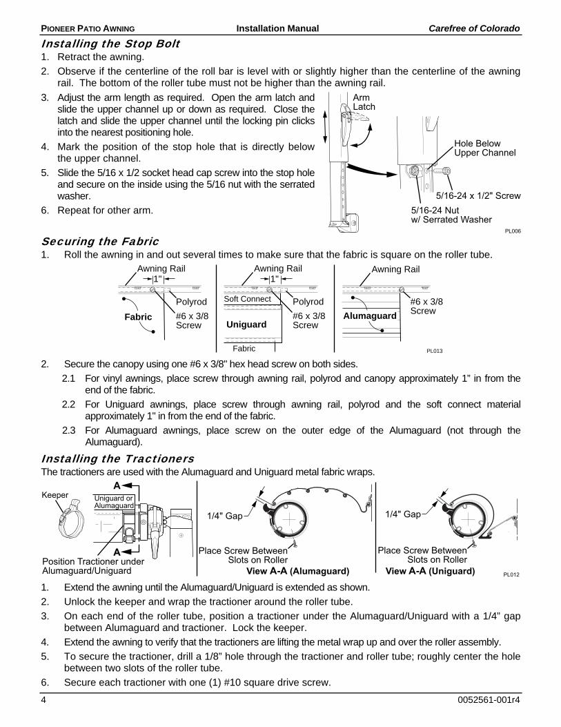
Installing the Stop Bolt 1. Retract the awning.
2. Observe if the centerline of the roll bar is level with or slightly higher than the centerline of the awning rail. The bottom of the roller tube must not be higher than the awning rail.
3. Adjust the arm length as required. Open the arm latch and slide the upper channel up or down as required. Close the latch and slide the upper channel until the locking pin clicks into the nearest positioning hole.
4. Mark the position of the stop hole that is directly below the upper channel.
5. Slide the 5/16 x 1/2 socket head cap screw into the stop hole and secure on the inside using the 5/16 nut with the serrated washer.
6. Repeat for other arm.
Securing the Fabric 1. Roll the awning in and out several times to make sure that the fabric is square on the roller tube.
2. Secure the canopy using one #6 x 3/8" hex head screw on both sides.
2.1 For vinyl awnings, place screw through awning rail, polyrod and canopy approximately 1” in from the end of the fabric.
2.2 For Uniguard awnings, place screw through awning rail, polyrod and the soft connect material approximately 1" in from the end of the fabric.
2.3 For Alumaguard awnings, place screw on the outer edge of the Alumaguard (not through the Alumaguard).
Installing the Tractioners The tractioners are used with the Alumaguard and Uniguard metal fabric wraps.
1. Extend the awning until the Alumaguard/Uniguard is extended as shown.
2. Unlock the keeper and wrap the tractioner around the roller tube.
3. On each end of the roller tube, position a tractioner under the Alumaguard/Uniguard with a 1/4” gap between Alumaguard and tractioner. Lock the keeper.
4. Extend the awning to verify that the tractioners are lifting the metal wrap up and over the roller assembly.
5. To secure the tractioner, drill a 1/8” hole through the tractioner and roller tube; roughly center the hole between two slots of the roller tube.
6. Secure each tractioner with one (1) #10 square drive screw.
Alumaguard
PL013Fabric
Fabric
1"
#6 x 3/8Screw
Polyrod
Awning Rail
Uniguard
Soft Connect
1"
#6 x 3/8Screw
Polyrod
Awning Rail
#6 x 3/8Screw
Awning Rail
1/4" Gap
A
A
View A-A (Uniguard)Position Tractioner underAlumaguard/Uniguard
Keeper
1/4" Gap
Uniguard orAlumaguard
View A-A (Alumaguard) PL012
Place Screw BetweenSlots on Roller
Place Screw BetweenSlots on Roller
ArmLatch
PL006
Hole BelowUpper Channel
5/16-24 x 1/2" Screw5/16-24 Nutw/ Serrated Washer

Carefree of Colorado Installation Manual PIONEER PATIO AWNING
052561-001r4 5
FACTORY INSTALLED LEDS (OPTIONAL) SPECIFICATIONS
Mounting Options:
a) LED light strip is mounted in the roller tube. The power harness is concealed in the canopy hem.
b) LED light strip is mounted at the awning rail. Requires special canopy with integrated strip holder.
Length: Available for awnings 10' – 21'
Power: 1A, 12Vdc
Color: Bright White 6000K (standard)
Control: Single pole, single throw switch (SR0101) Note: For an installer furnished switch, see notes in "Switch Installation" on page 6
NOTICE The following information must be followed to avoid damage to the wiring during and
after installation.
a) The wire should be secured to the wall of the vehicle where it is exposed on the outside of the vehicle. Use a quality silicone sealant/adhesive.
b) Do not route the wire over sharp edges or heat sources that can damage the wires or wire insulation.
c) Damage that is a result of improper routing may void warranty.
WHITE LED SCHEMATIC AND LAYOUT
HARNESS ROUTING INTO THE VEHICLE 1. Drill a 3/16" hole into the vehicle wall below the right edge of the canopy.
2. Route the wires from the canopy into the vehicle. Allow slack in the wire between the canopy and the wall. Seal the hole and wires with a quality silicone sealant.
3. Attach excess wires and connectors (for awning rail applications) along the bottom of the awning rail using a quality silicone sealant.
NOTE: There is approximately 8 feet of wire from the wall entry point. Controls should be located within this distance.
LED002a
LED Strip
Vehicle Wall
Red
+12VDC
GNDSingle Pole
Single Throw Switch18awg Wire
(minimum)
Red
Bla
ck
18-24awgFemale Disconnect (x2)
2A In-line Fuse
Power Harness
LED Holderat Awning Rail
Roller Tube Mount
LED Stripin LED Slot
Power HarnessSewn in Canopy Hem
3/16" Hole
Route Wire With SlackBetween Canopy and Wall
Attach Wires AlongBottom of Awning Rail
Canopy Harness Awning Rail LED
3/16" Hole
PIONEER PATIO AWNING Installation Manual Carefree of Colorado
6 0052561-001r4
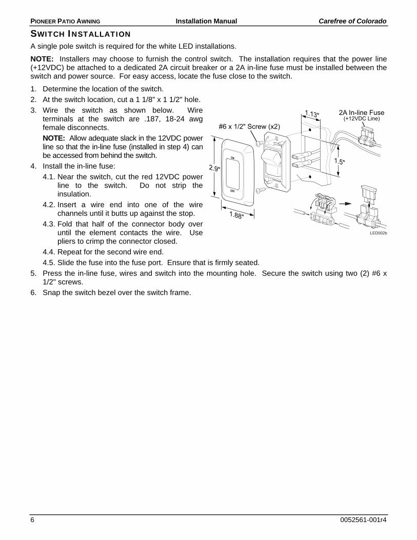
SWITCH INSTALLATION A single pole switch is required for the white LED installations.
NOTE: Installers may choose to furnish the control switch. The installation requires that the power line (+12VDC) be attached to a dedicated 2A circuit breaker or a 2A in-line fuse must be installed between the switch and power source. For easy access, locate the fuse close to the switch.
1. Determine the location of the switch.
2. At the switch location, cut a 1 1/8" x 1 1/2" hole.
3. Wire the switch as shown below. Wire terminals at the switch are .187, 18-24 awg female disconnects.
NOTE: Allow adequate slack in the 12VDC power line so that the in-line fuse (installed in step 4) can be accessed from behind the switch.
4. Install the in-line fuse:
4.1. Near the switch, cut the red 12VDC power line to the switch. Do not strip the insulation.
4.2. Insert a wire end into one of the wire channels until it butts up against the stop.
4.3. Fold that half of the connector body over until the element contacts the wire. Use pliers to crimp the connector closed.
4.4. Repeat for the second wire end.
4.5. Slide the fuse into the fuse port. Ensure that is firmly seated.
5. Press the in-line fuse, wires and switch into the mounting hole. Secure the switch using two (2) #6 x 1/2" screws.
6. Snap the switch bezel over the switch frame.
ON
OFF
1.13"
1.5"
1.88"
2.9"
#6 x 1/2" Screw (x2)
2A In-line Fuse(+12VDC Line)
LED002b