Embed Size (px)
Citation preview

Leading the way ...Leading the way ...
Installation Manual940
Leading the way ...
Door Automation

1
ENGLISH ENGLISH
1) CAUTION! It is important for personal safety to follow all the instructionscarefully. Incorrect installation or misuse of the product may causepeople serious harm.
2) Read the instructions carefully before starting to install the product.
3) Packaging material (plastic, polystyrene, etc.) must not be left within reachof children as it is a potential source of danger.
4) Keep the instructions for future reference.
5) This product was designed and manufactured strictly for the use indicatedin this documentation. Any other not expressly indicated use may damagethe product and/or be a source of danger.
6) FAAC accepts no responsibility due to improper use of the automatedsystem or use other than that intended.
7) Do not install the equipment in an area subject to explosion hazard:inflammable gases or fumes are a serious safety hazard.
8) The system must be carried out in compliance with the following Standards:EN 12604, EN 12605, EN 12453, EN 12445. To obtain an adequate level ofsafety in non EU countries, the above mentioned Standards must beobserved in addition to national Standards.
9) FAAC will not accept responsibility if the principles of Good Workmanshipare disregarded in constructing the closing elements to be motorised, andif any deformation occurs during use of the said elements.
10) Before carrying out any work on the system, switch off the power supply.
11) The mains power supply of the automated system must be fitted with a all-pole switch with contact opening distance of 3mm or greater. Use of a 6Athermal breaker with all-pole circuit break is recommended.
12) Make sure there is a differential switch with 0.03A threshold upstream of thesystem.
13) Check that the earthing system is correctly made and connect the closuremetal parts to it.
14) The automated system includes an intrinsic anti-crushing device consistingof a torque control which, however, must be installed together with othersafety devices.
15) The safety devices (EN 12978 Standard) protect any dangerous areasagainst Mechanical movement risks, such as crushing, dragging, andshearing.
CE DECLARATION OF CONFORMITY FOR MACHINES(DIRECTIVE 98/37/EC)
Manufacturer: FAAC S.p.A.
Address: Via Benini, 1 - 40069 Zola Predosa BOLOGNA - ITALY
Declares that: 940 SM - SMD mod. operator
• is built to be integrated into a machine or to be assembled with other machinery to create a machine underthe provisions of Directive 98/37/EC;
• conforms to the essential safety requirements of the following EEC directives:
73/23/EEC and subsequent amendment 93/68/EEC.89/336/EEC and subsequent amendment 92/31/EEC and 93/68/EEC
and also declares that it is prohibited to put into service the machinery until the machine in which it will beintegrated or of which it will become a component has been identified and declared as conforming to theconditions of Directive 98/37/EC.
Bologna, 01 January 2003The Managing Director
A. Bassi
16) A warning sign adequately fitted on the leaves, in addition to the devicesmentioned under point "15", must be used for each system.
17) FAAC accepts no responsibility regarding safety and correct operationof the automated system, should components made by manufacturersother than FAAC be used in the system.
18) Use only FAAC original spare parts for maintenance.
19) Do not make any alterations to the components of the automated system.
20) The installer shall supply full information regarding manual operation ofthe system in case of an emergency.
21) Do not allow children or other persons to stand near the product while inoperation.
22) Keep remote controls or any other pulse generator well away fromchildren, to prevent the automated system from being activatedaccidentally.
23) The user must refrain from attempting to repair or adjust the systempersonally and should contact qualified personnel only.
24) Anything not expressly provided for in these instructions is not permitted.
WARNINGS FOR THE INSTALLERGENERAL SAFETY OBLIGATIONS

2
ENGLISHENGLISH
�
�
�
�
�
�
�
KEY TO PROFILES
� � � � � SUPPORT PROFILE����� HOUSING PROFILE� � � � � SLIDING PROFILE� � � � � CLOSING PROFILE FOR STANDARD AUTOMATED SYSTEM� � � � � LEAF ATTACHMENT PROFILE� � � � � LEAF BOTTOM PROFILE� � � � � GRIPPER FOR GLASS LEAVES� � � � � BOTTOM SLIDING BLOCK FOR GLASS LEAF
�

3
ENGLISH ENGLISH
Tx
Rx
230V
~
Fig. 1
��
��
�
� �
�
�
�
�
�
��
�
Po
we
r su
pp
ly 2
30V~
N°
�
DES
CRI
PTIO
NC
ABL
ES
�
Exte
rna
l ra
da
r
Inte
rna
l ra
da
r� �
Tra
nsm
itte
r
Re
ce
ive
r
�SD
- K
ee
pe
r
4x0.
25m
m²
4x0.
25m
m²
2x0.
25m
m²
3x0.
25m
m²
�
2x0.
5mm
² ma
x 50
m
SD -
Ke
ep
er s
witc
hw
ith lo
ck
key
2x0.
5mm
²
�Em
erg
/Ke
y/R
ese
tc
on
tro
l pu
sh-b
utt
on
s2x
0.5m
m²
�3x
1.5m
m²
TAB.
1TE
CH
NIC
AL S
PEC
IFIC
ATI
ON
SAV
AILA
BLE M
ODEL
SHe
ad pr
ofile
Num
ber o
f leav
esLe
af m
axim
um w
eigh
tW
idth
of fr
ee tr
ansit
spac
e Vp
Max
thic
knes
s of fr
amed
leaf
Max a
bsor
bed p
ower
Powe
r sup
ply
Prot
ectio
n cla
ssAn
ti-cr
ushi
ng ac
tivat
ion
Oper
atin
g am
bien
t tem
pera
ture
Use f
requ
ency
Moto
r pow
er su
pply
Head
prof
ile le
ngth
Open
ing s
peed
adju
stmen
t (lo
ad-fr
ee)
Clos
ing s
peed
adju
stmen
t (lo
ad-fr
ee)
Partia
l ope
ning a
djus
tmen
tPa
use t
ime a
djustm
ent
Nigh
t pau
se tim
e adj
ustm
ent
Fails
afe o
n pho
toce
lls
IP 2
3 (in
door
use
)
940S
MD1
940S
M194
0SM2
940S
MD2
Supp
ort
Supp
ort
12
12
800÷
3000
700÷
3000
800÷
3000
700÷
3000
100%
-20°
C ÷
+55°
C
115V
/ 230
V~ 5
0/60
Hz10
0W
24Vd
c
5 ÷
70 c
m/s
ec.
5 ÷
70 c
m/s
ec.
10 ÷
140
cm
/sec
.10
÷ 1
40 c
m/s
ec.
on o
peni
ng /c
losin
g
0 ÷
90 se
c.0
÷ 24
0 se
c.
140
110
+ 11
025
018
0 +
180
10%
÷ 90
%
60 m
m�
1.EL
ECTR
ICA
L EQ
UIP
MEN
T
can
be d
isabl
ed
200W
See
figs.
3 to
8

4
ENGLISHENGLISH
1515
9,5
179,5
34,5
±10
25
50
130,
540
100
180
173
Fig. 2
�
�
��

5
ENGLISH ENGLISH
Emergency batteries (fig. 1 ref. �)In the event of a mains power cut, on-battery operationprovides a range of 30 minutes at 100% use frequency.The battery charge status test is automatic and indicated bya LED.The charge control board is designed for remote activation ofa 'battery operating' signal.
3.2 Supplementary accessoriesThese are the peripheral accessories for completing theautomated system.
-Miniswitch photocells-T20E : outdoor key-operated selector switch-T20I : flush-fitting key-operated selector switch-T21EF : Outdoor key-operated selector switch designed formotor release-T21IF : Flush-fitting key-operated selector switch designed formotor release-Detection sensors.-SD Keeper
3.3 Door frame accessoriesTo facilitate adapting the door frame profile to the carriagesand to enable correct finishing of the installation, FAAC offersthe following series of articles:
Closing profile (fig. 2 ref. �)Available in natural and anodised aluminium versions, theprofile is used for closing the space between the mobile leafand the wall on which the head profile is secured.
Brush for closing profiles (fig. 2 ref. �)Prevents dust reaching inside the head profile.
Pair of sliding blocks (fig.13 ref.2)Supplied as a pair, they can be secured to the wall (or on thestationary leaf) or directly on the floor.
Bottom track profile (fig. 13 ref. �)Allows the bottom leaf profile to adapt to the sliding blockmentioned above.
Brush for bottom track profile (fig. 13 ref. �)This completes the on-ground track system.
Leaf attachment profile (fig. 16 ref. �)Allows the top leaf profile to adapt to the carriageattachments.
Pair of bottom sliding blocks for glass leafThey enable the glass leaves to slide.
4. HEAD PROFILE CONFIGURATIONTo correctly position the head profile parts, refer to thedimensions in figures 3,4 and 5 for model SM and figures 6,7and 8 for twin-motor model (SDM).
With the FAAC series 940 SM systems, single- or double-leafsliding doors can be automatically activated, managed andcontrolled.The FAAC series 940 automated systems are supplied fullyassembled, wired and tested in the configuration requestedby the customer on the order form, or supplied as a kit.An automation head profile (fig.1 ) consists of the followingparts:
Profile SM (fig. 2 ref.�)This is the support profile which is used when the head profilecan be entirely fitted on a bearing structure. The profile'ssliding track is coated with a special plastic material which, inaddition to protecting the aluminium profile against wear,ensures silent operation with a very low friction coefficient.
Leaf support carriages (fig.1 ref.�)The carriages are provided with two wheels on ball bearings,a counter wheel on the lower part, and a screw system foradjusting leaf height.
Motor unit (fig. 1 ref. �)The DC motor is supplied with an encoder and a leaf lockingsystem (accessory).
Control unit (fig. 1 ref. �)When the microprocessor control unit is powered up, itexecutes an initialisation process of the door's functionalparameters.
Transformer (fig. 1 ref. �)Opening mechanical stop (fig. 1 ref. �)Transmission pulley unit (fig. 1 ref. �)Second motor (fig. 1 ref. �)Drive chain (fig. 1 ref. �)
3. ACCESSORIESFAAC has three groups of articles complementing theinstallation of the automatic door.
3.1 Supplied accessories for the head profileThese are the articles which, following a request on the orderform, are assembled on the head profile directly by FAAC.These accessories, which can be, if necessary, installed lateron, are as follows:
Front housing (fig. 2 ref. �)The front housing is available in natural or anodisedaluminium.The side panels fully enclose the system.
Motor lock unitThe motor lock unit guarantees mechanical locking of thedoor in any position. A single type of motor lock is used foreither single- or double-leaf applications.The motor lock is supplied with an internal release device (fig.1 ref. ) enabling emergency opening if necessary; it is alsodesigned for installation of the external release (paragraph 3.2key push-buttons T21EF and T21IF). The motor lock unit actsdirectly on the motor by locking it mechanically.
Motor lock controlThis controls if the motor lock operating efficiently and checks if thedoor has actually closed. If necessary, the system is designed forremote activation of an indicator-light or buzzer.
940SM-SMD SERIES AUTOMATIC DOORS
2. DESCRIPTION AND TECHNICAL SPECIFICATIONS

6
ENGLISHENGLISH
CI
70
Vp
B
Lt
Vp Lt B C D I700 1500 490 335 1870 865800 1700 590 535 2070 965900 1900 690 635 2270 10651000 2100 790 735 2470 11651100 2300 890 835 2670 12651200 2500 990 935 2870 13651300 2700 1090 1035 3070 14651400 2900 1190 1135 3270 15651500 3100 1290 1235 3470 16651600 3300 1390 1335 3670 17651700 3500 1490 1435 3870 18651800 3700 1590 1535 4070 19651900 3900 1690 1635 4270 20652000 4100 1790 1735 4470 21652100 4300 1890 1835 4670 22652200 4500 1990 1935 4870 23652300 4700 2090 2035 5070 24652400 4900 2190 2135 5270 25652500 5100 2290 2235 5470 26652600 5300 2390 2335 5670 27652700 5500 2490 2435 5870 28652800 5700 2590 2535 6070 29652900 5900 2690 2635 6270 30653000 6100 2790 2735 6470 3165
Vp = Free transit spaceLt = Head profile lengthB = Securing distance of carriages on sliding leafC = Motor positioning dimensionD = Length of transmission beltI = Motor/transmission unit distance
Fig. 3
940 SM Right opening
SM t
ran
smis
sio
n u
nit
SM C
on
tro
l b
oa
rd u
nit
Mo
tor
Lt = Vp x 2 + 100
Tra
nsf
orm
er/
bu
ffe
rb
att
erie
s un
it

7
ENGLISH ENGLISH
IC
Vp
70B
Lt
Vp Lt B C D I700 1500 510 450 1990 925800 1700 590 585 2070 965900 1900 690 685 2270 10651000 2100 790 785 2470 11651100 2300 890 885 2670 12651200 2500 990 985 2870 13651300 2700 1090 1085 3070 14651400 2900 1190 1185 3270 15651500 3100 1290 1285 3470 16651600 3300 1390 1385 3670 17651700 3500 1490 1485 3870 18651800 3700 1590 1585 4070 19651900 3900 1690 1685 4270 20652000 4100 1790 1785 4470 21652100 4300 1890 1885 4670 22652200 4500 1990 1985 4870 23652300 4700 2090 2085 5070 24652400 4900 2190 2185 5270 25652500 5100 2290 2285 5470 26652600 5300 2390 2385 5670 27652700 5500 2490 2485 5870 28652800 5700 2590 2585 6070 29652900 5900 2690 2685 6270 30653000 6100 2790 2785 6470 3165
Fig. 4
940 SM Left opening
SM t
ran
smis
sio
n u
nit
SM C
on
tro
l b
oa
rd u
nit
Lt = Vp x 2 + 100
Vp = Free transit spaceLt = Head profile lengthB = Securing distance of carriages on sliding leafC = Motor positioning dimensionD = Length of transmission beltI = Motor/transmission unit distance
Mo
tor
Tra
nsf
orm
er/
bu
ffe
rb
att
erie
s un
it

8
ENGLISHENGLISH
CI
Lt
2727
Vp
70B
B70
Vp Lt B C D I800 1700 225 205 2710 1285900 1900 275 257,5 2910 13851000 2100 325 307,5 3110 14851100 2300 375 357,5 3310 15851200 2500 425 407,5 3510 16851300 2700 475 457,5 3710 17851400 2900 525 507,5 3910 18851500 3100 575 557,5 4110 19851600 3300 625 607,5 4310 20851700 3500 675 657,5 4510 21851800 3700 725 707,5 4710 22851900 3900 775 757,5 4910 23852000 4100 825 807,5 5110 24852100 4300 875 857,5 5310 25852200 4500 925 907,5 5510 26852300 4700 975 957,5 5710 27852400 4900 1025 1007,5 5910 28852500 5100 1075 1057,5 6110 29852600 5300 1125 1107,5 6310 30852700 5500 1175 1157,5 6510 31852800 5700 1225 1207,5 6710 32852900 5900 1275 1257,5 6910 33853000 6100 1325 1307,5 7110 3485
Fig. 5
940 SM Double-leaf
SM t
ran
smis
sio
n u
nit
SM C
on
tro
l b
oa
rd u
nit
Mo
tor
Lt = Vp x 2 + 100
Tra
nsf
orm
er/
bu
ffe
rb
att
erie
s un
it
Vp = Free transit spaceLt = Head profile lengthB = Securing distance of carriages on sliding leafC = Motor positioning dimensionD = Length of transmission beltI = Motor/transmission unit distance

9
ENGLISH ENGLISH
CI
Lt 70
Z(1
00)
Vp
B
Fig. 6
Vp Lt B C D I700 1600 490 420 2040 950800 1800 590 435 2240 1050900 2000 690 535 2440 11501000 2200 790 635 2640 12501100 2400 890 735 2840 13501200 2500 990 835 2870 13651300 2700 1090 935 3070 14651400 2900 1190 1035 3270 15651500 3100 1290 1135 3470 16651600 3300 1390 1235 3670 17651700 3500 1490 1335 3870 18651800 3700 1590 1435 4070 19651900 3900 1690 1535 4270 20652000 4100 1790 1635 4470 21652100 4300 1890 1735 4670 22652200 4500 1990 1835 4870 23652300 4700 2090 1935 5070 24652400 4900 2190 2035 5270 25652500 5100 2290 2135 5470 26652600 5300 2390 2235 5670 27652700 5500 2490 2335 5870 28652800 5700 2590 2435 6070 29652900 5900 2690 2535 6270 30653000 6100 2790 2635 6470 3165
940 SMD Right opening
Vp = Free transit spaceLt = Head profile lengthB = Securing distance of carriages on sliding
leafC = Motor positioning dimensionD = Length of transmission beltI = Motor/second motor distance
SM C
on
tro
l b
oa
rd u
nit
Mo
tor
Tra
nsf
orm
er/
bu
ffe
rb
att
erie
s un
itSe
co
nd
Mo
tor
un
it
If 700 � Vp � 1100 thenLt = Vp x 2 + 200
If Vp > 1100 thenLt = Vp x 2 + 100

10
ENGLISHENGLISH
CI
LtZ
(100
)
70B
Vp
940 SMD Left opening
Fig. 7
Vp Lt B C D I700 1600 480 440 2100 980800 1800 590 485 2300 1080900 2000 690 585 2500 11801000 2200 790 685 2700 12801100 2400 890 785 2900 13801200 2500 990 885 2870 13651300 2700 1090 985 3070 14651400 2900 1190 1085 3270 15651500 3100 1290 1185 3470 16651600 3300 1390 1285 3670 17651700 3500 1490 1385 3870 18651800 3700 1590 1485 4070 19651900 3900 1690 1585 4270 20652000 4100 1790 1685 4470 21652100 4300 1890 1785 4670 22652200 4500 1990 1885 4870 23652300 4700 2090 1985 5070 24652400 4900 2190 2085 5270 25652500 5100 2290 2185 5470 26652600 5300 2390 2285 5670 27652700 5500 2490 2385 5870 28652800 5700 2590 2485 6070 29652900 5900 2690 2585 6270 30653000 6100 2790 2685 6470 3165
SM C
on
tro
l b
oa
rd u
nit
If 700 � Vp � 1100 thenLt = Vp x 2 + 200
If Vp > 1100 thenLt = Vp x 2 + 100
Mo
tor
Tra
nsf
orm
er/
bu
ffe
rb
att
erie
s un
itSe
co
nd
Mo
tor
un
itVp = Free transit spaceLt = Head profile lengthB = Securing distance of carriages on sliding
leafC = Motor positioning dimensionD = Length of transmission beltI = Motor/second motor distance

11
ENGLISH ENGLISH
CI
Lt
2727
B70
70B
Vp
940 SMD Double-leaf
Fig. 8
Vp Lt B C D I800 1700 225 205 2710 1285900 1900 275 257,5 2910 13851000 2100 325 307,5 3110 14851100 2300 375 357,5 3310 15851200 2500 425 407,5 3510 16851300 2700 475 457,5 3710 17851400 2900 525 507,5 3910 18851500 3100 575 557,5 4110 19851600 3300 625 607,5 4310 20851700 3500 675 657,5 4510 21851800 3700 725 707,5 4710 22851900 3900 775 757,5 4910 23852000 4100 825 807,5 5110 24852100 4300 875 857,5 5310 25852200 4500 925 907,5 5510 26852300 4700 975 957,5 5710 27852400 4900 1025 1007,5 5910 28852500 5100 1075 1057,5 6110 29852600 5300 1125 1107,5 6310 30852700 5500 1175 1157,5 6510 31852800 5700 1225 1207,5 6710 32852900 5900 1275 1257,5 6910 33853000 6100 1325 1307,5 7110 3485
SM C
on
tro
l b
oa
rd u
nit
Lt = Vp x 2 + 100
Mo
tor
Tra
nsf
orm
er/
bu
ffe
rb
att
erie
s un
it
Sec
on
d M
oto
r u
nit
Vp = Free transit spaceLt = Head profile lengthB = Securing distance of carriages on sliding
leafC = Motor positioning dimensionD = Length of transmission beltI = Motor/second motor distance

12
ENGLISHENGLISH
5. INSTALLATION
Fig. 9
140
9,5
± 10
HA = (LH-20,5 mm) ± 10
LH (
ma
x 25
00)
HA

13
ENGLISH ENGLISH
The support profile is used when the head profile can be fullyfixed to a metal or masonry bearing structure not showingsignificant deformations.
Support profile - securing it to the wall•Establish the exact location of the head profile consideringthe overall dimensions of fig. 2. The head profile must besecured parallel to the floor.•To begin with, fit the head profile on a vertical slot at oneend and on a horizontal slot at the other end (using M8screws and appropriate expansion plugs), and level parallelto the floor.Secure at the centre, firmly lifting the head profile to align thethree securing points. Carry out the remaining securingoperations, alternating vertical and horizontal slots (fig. 10).
ATTENTION: insert the brush (accessory fig.11 ref. �) in theclosing profile before installing.
6. SECURING THE HEAD PROFILE
Fig. 11�
Fig. 10
6.1 Installation of side panels
•Fit the side panels as shown in figures 12.The side panels are engraved so that they can adapt tohead profiles with or without a free-standing profile.
Fig. 12
7. INSTALLATION OF BOTTOM SLIDING BLOCKS
The bottom sliding blocks are designed for securing to the wall(or stationary leaf) or to the floor.Securing on the wall (or on stationary leaf):•Assemble the sliding blocks, considering in mind thedimensions in figs.13 and 15.•Secure the sliding blocks as shown in fig. 14. ref. �.Securing on the floor•Secure the sliding block directly to the floor, as shown in fig.14. ref. �, using adequate expansion plugs and screws.
30
1218
14,5
35
30 - 42
Fig. 13
�
�
Fig. 14
�
�
�
30
1218
7
14,5
3561 -75
Fig. 15
8. INSTALLATION OF THE LEAVES
•Fit the leaf attachment profile (accessory fig.16 ref. �) on thetop of the leaf, using adequate screws.•Secure the leaf on the relevant carriages, using the suppliedplates (fig.16 ref. �) and screws (fig. 16 ref. �).•Position the carriages of the automated system as shown infigures from3 to 8.•Tighten the screws of the carriages.

14
ENGLISHENGLISH
The carriages enable height adjustment of the leaves.Adjustment procedure:•Slightly loosen the two hexagon head screws in fig. 17 ref. �.•Turn the screw (fig.17 ref. �) clockwise to raise the leaves oranti-clockwise to lower them.•Re-tighten the screws.
� �
�
Fig. 17
� Fig. 16
�
�
8.2 Adjustment of the counter roller
The carriages are supplied with a counter wheel. Adjustmentprocedure below:•Loosen the two hexagon head screws (fig. 17 ref � and �).•Slide the screw fig. 17 ref. � inside the slot, so that, while thecarriage is moving, the counter wheel slides on the profilewithout jamming.Check if the wheel can be locked without stopping thecarriage.
� �
9. ADJUSTMENT OF THE TRAVEL STOP LIMITS
Adjustment of the opening mechanical stopsThe 940 SM series doors are supplied with the openingmechanical stops mounted on the sliding profile.Make sure that, when the leaves are being opened, thesliding carriages simultaneously reach the opening travel limitmechanical stops.If adjustments are necessary, proceed as follows:•Take the leave into opening position.•Loosen the two hexagon head screws as shown in figures 18and 19 ref. �.•Take the mechanical stop toward the carriage until the twoparts come into contact.•Tighten the two hexagon head screws.
Adjustment of the closing mechanical stop.The 940 SM series doors are supplied with the carriagesreaching their trave stop limit on the closing edge (fig.20). Ifthe door centre has to be adjusted, proceed as follows:
8.1 Leaf adjustment
•Loosen the fixing screws (fig. 20 ref. �) of the carriage inquestion. Take the carriage toward the limit stop until the twoparts are in contact.•Tighten the carriage's fixing screws.
�
�Fig. 19
Fig. 18
Fig. 20� �
10. BELT ADJUSTMENT
Check if the belt is too slack or taut.Belt tension adjustment procedure:•Loosen the nut (fig. 21 ref. �).•Screw the bolt of fig. 21 ref. � to exert tension on the belt orunscrew it to slacken the belt.•When you have adjusted tension, tighten the nut (fig. 21 ref.�).
Fig. 21
�
�
To adjust belt tension for twin-motor doors, proceed as follows:•Slightly loosen the four fixing screws (fig. 22 ref. �) of thesecond motor.•Push the motor unit outwards using a hammer as shown infig. 22.•When you have adjusted tension, tighten the four screws.

15
ENGLISH ENGLISH
11. INSTALLATION OF HOUSING FIXING BRACKETS
•Fit a housing fixing bracket at the end of the head profile,opposite the motor unit, using the supplied screws and plates(fig.23).•Fit the second housing fixing bracket slightly off-centre of thehead profile, to enable you to make the door-centreadjustments.•Secure the bracket supporting the internal release knob tothe other end of the head profile (on the motor unit side), asshown in fig. 24. The support bracket of the internal release knob must alwaysbe installed, even if the motor lock is not used.
Fig. 23
Fig. 24
12. MOTOR LOCK
The motor lock is a device guaranteeing the leaves arelocked when closed.Installation procedure:•Secure the motor lock with the two supplied bolts as shownin fig. 25 ref. �.•Manually push the lever (fig. 26 ref. �) toward the motorshaft, checking for correct meshing as per fig. 26 ref. A.•Move the lever (fig. 26 ref. �) vertically and check if there isplay between the motor-shaft and motor-lock coupling.
Fig. 25
�
�
Fig. 22
Fig. 26
�
A
B
If there is no play on the coupling, proceed as follows:•Loosen the two screws (fig. 27 ref. �) on both carriages.•Slightly move the belt horizontally until the lever movessmoothly; tighten the screws on the carriages.

16
ENGLISHENGLISH
Fig. 27
�
12.1 Installation of internal release knob
•Assemble the release knob as indicated in fig. 28 ref. �.•Press the contrast washer until it fits in the release knob.•Screw the adjuster, with the relevant lock nuts, on theinternal part of the bracket (fig. 28 ref. �).•Fit the cable inside the adjuster, threading it through thewasher and the release knob.•Secure the steel cable with the cable gland and theappropriate screw (fig. 28 ref. �).•Pull the cable up to the cable gland stop inside the knob.•Take the cable sheath against the adjuster (fig. 28 ref. �).
12.2 Motor lock adjustment•Fully screw the adjuster on the bracket.•Pull the knob and rotate it through 90° so that it locks on thebracket.•Thread the cable (fig. 29 ref. �) inside part � , leaving thesheath at its limit stop.•Fit the cable on the terminal (fig. 29 ref. �).•Pull part � to its limit stop (compressing the springs) andtighten the screw of the terminal �, thus securing the steelcable.•Make sure that the motor lock coupling is clear of the motorshaft coupling (fig. 26 ref. B).•If adjustments are required, turn the knob bracket adjuster.•Release the knob rotating it through 90° and check if therelease is efficient.
� �
�
�
Fig. 29
Fig. 28
�
�
�
�
13. FITTING THE HOUSING•Fit three spacers (fig. 30 ref �)on the outer edge of the supportprofile, positioning them at the ends and at the centre.
Fig. 30
�
•Lay the housing on the spacers.•To keep the housing open, lift it and push it toward theprofile until the metal projection fits into the profile seat (fig.31ref. �).•Fasten the 'parachute' cables on the housing and on thehousing fixing brackets as shown in fig. 31 ref. �.•The housing is secured on the brackets with the appropriatehooks (fig. 32).•Break off the excess lower housing profile with a pair of pliers(fig. 32 rif. �).N.B.: To ensure correct closure of the housing, if using theinternal release, shape the housing to the dimensions in fig. 33.
Fig. 31
�
�

17
ENGLISH ENGLISH
15. INSTALLATION OF BUFFER BATTERIES
Fit the buffer batteries inside the transformer unit (fig. 35).
Fig. 35
Fig. 32
�
R20
4040
50
Fig. 33
14. INSTALLATION OF CABLE SLEEVES
Fit the supplied cable sleeves parallel to the profile ( fig. 34 ref.�)and then turn them by 90° to secure them (fig. 34 ref. �).
� �
Fig. 34

18
ENGLISHENGLISH
Fig. 36
16. INSTALLATION WITH GRIPPERS FOR GLASS LEAVES
HA = LH - (4,5 + 23,5) + 21 ± 10mm
To install with the glass leaves grippers, refer to the dimensionsin figure. 36.
LH (
ma
x 25
00)
HA

19
ENGLISH ENGLISH
17. START-UP
•To remove the protective cover of the SDM control unit,delicately obtain leverage with a screwdriver as shown in fig.37.•To refit it, attach it on the top part and press as shown infig.38.•To remove the motor unit's cover, loosen the screws.•Manually check correct movement of the leaves and allmoving elements.•Make/check all electrical connections on the SDM board ofthe power cables from the toroidal transformer, from the motorand from all accessories - routing the cables inside the pre-fitted cable sleeves.•Set motor direction of rotation according to type of door(refer to the instructions of the SDM board).•Check if a jumper is present on terminal board J7 of the SDMboard (refer to the SDM board).•Connect the 230V power cables to the terminals inside thetransformer unit (fig. 39 ref. �).Note: a 1A time-delay fuse is also supplied to protect thetransformer.•Set automatic operating mode and execute setup.•Check the efficiency of all installed accessories, especiallyphotocells and sensors.
�Fig. 39
Fig. 38
Fig. 37

20
ENGLISH ENGLISH
MAIN
V ACC
V MOT
+ 24V
OUT 3
OUT 2
OUT 1
KEY
E-DET
I-DET
PSW 1
PSW 2
EM.1
EM.2
OPENED
NIGHT
MONODIR
ERROR
DP1 2
ON
J8SW
5RESET
J5J6
J13J12
J11
F1F2
J1J3J7J2J4
SP-DOW
N
SETUP
SP-UP
LEDO
NO
FFM
AIN
220V~
ma
ins O
N220V
~ m
ain
s OFF
V A
CC
Va
cc
ON
Va
cc
OFF
V M
OT
mo
tor p
ow
ere
d u
pm
oto
r po
we
red
do
wn
+ 24V+
24V O
N+
24V O
FFO
UT 3
OU
T 3 co
nta
ct c
lose
dO
UT 3 c
on
tac
t op
en
OU
T 2O
UT 2 c
on
tac
t clo
sed
OU
T 2 co
nta
ct o
pe
nO
U 1
OU
T 1 co
nta
ct c
lose
dO
UT 1 c
on
tac
t op
en
KEY
KEY
inp
ut c
lose
dK
ey in
pu
t op
en
E-DET
E-DET in
pu
t clo
sed
E-DET in
pu
t op
en
I-DET
I-DET in
pu
t clo
sed
I-DET in
pu
t op
en
PSW 1
PSW
1 inp
ut c
lose
dP
SW 1 in
pu
t op
en
PSW 2
PSW
2 inp
ut c
lose
dP
SW 2 in
pu
t op
en
EM.1
EMER
G.1 in
pu
t clo
sed
EMER
G.1 in
pu
t op
en
EM.2
EMER
G.2 in
pu
t clo
sed
EMER
G.2 in
pu
t op
en
OPEN
EDO
PEN
ED in
pu
t clo
sed
OP
ENED
inp
ut o
pe
nN
IGH
TN
IGH
T inp
ut c
lose
dN
IGH
T inp
ut o
pe
nM
ON
OD
IRO
NE W
AY
inp
ut c
lose
dO
NE W
AY
inp
ut o
pe
nERRO
Rse
e ta
ble
LED ERRO
R STATU
SM
EAN
ING
OFF
no
rma
l op
era
ting
statu
sO
NA
larm
s n° 18,20,22,24: e
xec
ute
SETUP
SLOW
FLASH
ING
cu
rren
t ala
rm sig
na
lling
FAST FLA
SHIN
Gse
tup
/rese
t in p
rog
ress o
rd
urin
g se
tup
with
the
"kit ela
stic" a
ctiva
ted
1 2 3 4 5 6 7 8 9 10 11 12 13
1 2 3 4 5 6 7 8 9 10 11 12 13 14
940SDM CONTROL BOARD940SDM CONTROL BOARD940SDM CONTROL BOARD940SDM CONTROL BOARD940SDM CONTROL BOARD
PUSH
-BUTTO
NM
EAN
ING
RESETe
xec
ute
s rese
tSW
5p
ulse
on
“inte
rna
l sen
sor” in
pu
t (I-DET)
SETUP
exe
cu
tes a
uto
ma
tic se
tup
SP-DO
WN
red
uc
es c
losin
g sp
ee
dSP-U
Pin
cre
ase
s clo
sing
spe
ed
CO
NN
ECTO
RM
EAN
ING
J1c
on
ne
cto
r to J2 o
f sec
on
d m
oto
r bo
ard
J2c
on
ne
cto
r to J3 o
f sec
on
d m
oto
r bo
ard
J3m
oto
r qu
ick-fit c
on
ne
cto
rJ4
flat c
ab
le c
on
ne
cto
r for e
nc
od
er
J5te
rmin
al b
oa
rdJ6
term
ina
l bo
ard
J7N
OT A
US e
me
rge
nc
y stop
(NC
co
nta
ct)
J8R
S232 seria
l po
rt for P
C c
on
ne
ctio
nJ9
co
nn
ec
tor to
J5 of se
co
nd
mo
tor b
oa
rdJ11-J12-J13
co
nn
ec
tors fo
r ad
ditio
na
l co
ntro
l bo
ard
s
J9
DP
ON
OFF
Dip
n°1m
oto
r rota
tion
dire
ctio
n (se
e ta
ble
)D
ip n°2
RS232 p
ort se
tR
S232 po
rt set
for S/W
up
da
tefo
r PC
co
nn
ec
tion
FUSE
MEA
NIN
GF1
fuse
5x20 T 6.3A/250V
(mo
tor p
rote
ctio
n)
F2fu
se 5x20 T 1A
/250V (24V
pro
tec
tion
)

21
ENGLISH ENGLISH
J1J2
J6J9
J3J4
J7
MA
IN
S/P
VM
OT
24V
SP_D
OW
N
SETU
P
SP_U
P
DS1J5
J8
J10
F1
F2
1 2ON
SECOND MOTOR CONTROL BOARDSECOND MOTOR CONTROL BOARDSECOND MOTOR CONTROL BOARDSECOND MOTOR CONTROL BOARDSECOND MOTOR CONTROL BOARD
LED ON OFFMAIN 220V~ mains ON 220V~ mains OFFV MOT motor powered up motor powered down24V + 24V ON + 24V OFF
PUSH-BUTTON MEANINGSETUP inactiveSP-DOWN inactiveSP-UP inactive
DS1 MEANINGDip n°1 to be always positioned to OFFDip n°2 posizionare sempre in OFF
FUSE MEANINGF1 fuse 5x20 T 6.3A/250V (motor
protection)F2 fuse 5x20 T 1A/250V (24V
protection)
CONNECTOR MEANINGJ1 transformer 40V secondary windingJ2 connector to J1 of 940SDMJ3 connector to J2 of 940SDMJ4 transformer 24V secondary windingJ5 connector to J9 of 940SDMJ6 second motor quick-fit connectorJ7 not usedJ8 RS232 serial port for PC connectionJ9 NOT AUS emergency stop (NC contact)J10 connector to J3 of batteries board
S/P LED STATUS MEANINGOFF normal operating statusON no connetting to 940SDM board
INSTINSTINSTINSTINSTALLING SECOND MOTORALLING SECOND MOTORALLING SECOND MOTORALLING SECOND MOTORALLING SECOND MOTORBOARDBOARDBOARDBOARDBOARD
The assembled 940 twin-motor doors are supplied withpre-wired second-motor board.For Kit doors, fit thesecond board using the spacers provided andpositioning them on the 940SDM board to correspondto the holes as shown in fig. 1 rif. �. Wire up the two unitsusing the cables provided and following the diagram infig. 2.

22
ENGLISH ENGLISH
J1J2
J6J9
J3J4
J7
J10
J5
J9
J8
J8
J1J3
J7J2
J4
fig.1
�
�
�
�
fig.2
J10
J1J2
J6J9
J3J4
J7
J5
J1J3
J7J2
J4
J9
J1J2
J3
secondmotor
motor
Second motorboard
940SDM board
Batteries board
transformer 40Vsecondary winding
transformer24V secondarywinding

23
ENGLISH ENGLISH
TERMINAL BOARD J6 TERMINAL BOARD J5
12
345
678
91011
121314
EXTERNAL SENSOR
INTERNAL SENSOR
+ - C NO NC
+ - C NO NC
RESET$$$$$
EMERG 2EMERG 1
$$$$$
PSW 2PSW 1
$$$$$I -DETE-DET
- FAILSAFE
+ VACC
$$$$$
+ VACC
J5
12
3
45678
910111213
J6
SD-KEEPER
+ 24VOUT 3
$$$$$OUT 2
$$$$$
$$$$$OUT 1
KEY- SD-KEEPER+ SD-KEEPER
MONODIRNIGHT
OPENED
default configuration default configuration
$$$$$
PSW 2
PSW 1$$$$$
- FAILSAFE+ VACC
$$$$$
12345
6789
1011121314
J5
CONNECTION OF PHOTOCELLS WITH FAILSAFE DISABLED (DEFAULT)
no photocell 1 pair of photocells 2 pairs of photocells
$$$$$
PSW 2PSW 1
$$$$$
- FAILSAFE+ VACC
$$$$$
123456789
1011121314
RX1
TX1
+ - C
+ -
J5
$$$$$
PSW 2PSW 1
$$$$$
- FAILSAFE+ VACC
$$$$$
123
456789
1011121314
+ - C + - C
+ - + -
RX2
TX2
RX1
TX1
J5
CONNECTION OF PHOTOCELLS WITH FAILSAFE ENABLED
no photocell 1 pair of photocells 2 pairs of photocells
$$$$$
PSW 2PSW 1
$$$$$
- FAILSAFE+ VACC
$$$$$
12
3456
789
1011121314
RX1
TX1
+ - C
+ -
J5
$$$$$
PSW 2PSW 1
$$$$$
- FAILSAFE+ VACC
$$$$$
123
456789
1011121314
J5
$$$$$
PSW 2PSW 1
$$$$$
- FAILSAFE+ VACC
$$$$$
123456789
1011121314
RX2 RX1
TX2 TX1
+ - C + - C
+ - + -
J5
NOTE: Photocell inputs in connection diagrams are considered NC contacts (default configuration).
2x0.5mm2
max 50m
LOCK
24
ENGLISH ENGLISH
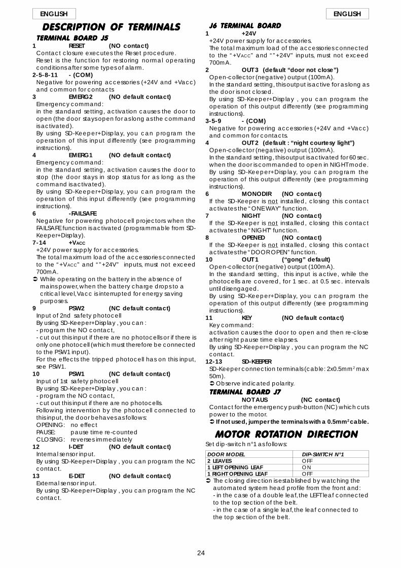
DESCRIPTION OF TERMINALSDESCRIPTION OF TERMINALSDESCRIPTION OF TERMINALSDESCRIPTION OF TERMINALSDESCRIPTION OF TERMINALSTERMINAL BOARD J5TERMINAL BOARD J5TERMINAL BOARD J5TERMINAL BOARD J5TERMINAL BOARD J5
1 RESET (NO contact)Contact closure executes the Reset procedure.Reset is the function for restoring normal operatingconditions after some types of alarm.
2-5-8-11 - (COM)Negative for powering accessories (+24V and +Vacc)and common for contacts
3 EMERG2 (NO default contact)Emergency command:in the standard setting, activation causes the door toopen (the door stays open for as long as the commandis activated).By using SD-Keeper+Display, you can program theoperation of this input differently (see programminginstructions).
4 EMERG1 (NO default contact)Emergency command:in the standard setting, activation causes the door tostop (the door stays in stop status for as long as thecommand is activated).By using SD-Keeper+Display, you can program theoperation of this input differently (see programminginstructions).
6 -FAILSAFENegative for powering photocell projectors when theFAILSAFE function is activated (programmable from SD-Keeper+Display).
7-14 +VACC
+24V power supply for accessories.The total maximum load of the accessories connectedto the “+VACC” and “”+24V” inputs, must not exceed700mA.
While operating on the battery in the absence ofmains power, when the battery charge drops to acritical level, Vacc is interrupted for energy savingpurposes.
9 PSW2 (NC default contact)Input of 2nd safety photocellBy using SD-Keeper+Display , you can :- program the NO contact,- cut out this input if there are no photocells or if there isonly one photocell (which must therefore be connectedto the PSW1 input).For the effects the tripped photocell has on this input,see PSW1.
10 PSW1 (NC default contact)Input of 1st safety photocellBy using SD-Keeper+Display , you can :- program the NO contact,- cut out this input if there are no photocells.Following intervention by the photocell connected tothis input, the door behaves as follows:OPENING: no effectPAUSE: pause time re-countedCLOSING: reverses immediately
12 I-DET (NO default contact)Internal sensor input.By using SD-Keeper+Display , you can program the NCcontact.
13 E-DET (NO default contact)External sensor input.By using SD-Keeper+Display , you can program the NCcontact.
J6 TERMINAL BOARDJ6 TERMINAL BOARDJ6 TERMINAL BOARDJ6 TERMINAL BOARDJ6 TERMINAL BOARD1 +24V
+24V power supply for accessories.The total maximum load of the accessories connectedto the “+VACC” and “”+24V” inputs, must not exceed700mA.
2 OUT 3 (default “door not close”)Open-collector (negative) output (100mA).In the standard setting, this output is active for as long asthe door is not closed.By using SD-Keeper+Display , you can program theoperation of this output differently (see programminginstructions).
3-5-9 - (COM)Negative for powering accessories (+24V and +Vacc)and common for contacts.
4 OUT 2 (default : “night courtesy light”)Open-collector (negative) output (100mA).In the standard setting, this output is activated for 60 sec.when the door is commanded to open in NIGHT mode.By using SD-Keeper+Display, you can program theoperation of this output differently (see programminginstructions).
6 MONODIR (NO contact)If the SD-Keeper is not installed, closing this contactactivates the “ONE WAY” function.
7 NIGHT (NO contact)If the SD-Keeper is not installed, closing this contactactivates the “NIGHT” function.
8 OPENED (NO contact)If the SD-Keeper is not installed, closing this contactactivates the “DOOR OPEN” function.
10 OUT 1 (“gong” default)Open-collector (negative) output (100mA).In the standard setting, this input is active, while thephotocells are covered, for 1 sec. at 0.5 sec. intervalsuntil disengaged.By using SD-Keeper+Display, you can program theoperation of this output differently (see programminginstructions).
11 KEY (NO default contact)Key command:activation causes the door to open and then re-closeafter night pause time elapses.By using SD-Keeper+Display , you can program the NCcontact.
12-13 SD-KEEPERSD-Keeper connection terminals (cable: 2x0.5mm2 max50m).
Observe indicated polarity.TERMINAL BOARD J7TERMINAL BOARD J7TERMINAL BOARD J7TERMINAL BOARD J7TERMINAL BOARD J7
NOT AUS (NC contact)Contact for the emergency push-button (NC) which cutspower to the motor.
If not used, jumper the terminals with a 0.5mm2 cable.
MOTOR ROTMOTOR ROTMOTOR ROTMOTOR ROTMOTOR ROTAAAAATION DIRECTIONTION DIRECTIONTION DIRECTIONTION DIRECTIONTION DIRECTIONSet dip-switch n°1 as follows:
DOOR MODEL DIP-SWITCH N°12 LEAVES OFF1 LEFT OPENING LEAF ON1 RIGHT OPENING LEAF OFF
The closing direction is established by watching theautomated system head profile from the front and:- in the case of a double leaf, the LEFT leaf connectedto the top section of the belt.- in the case of a single leaf, the leaf connected tothe top section of the belt.

25
ENGLISH ENGLISH
STSTSTSTSTARTARTARTARTART-UP-UP-UP-UP-UPThe first time the door is powered, the 940SDM controlboard automatically executes a setup procedure andloads all the standard configuration settings.
STSTSTSTSTANDARD CONFIGURAANDARD CONFIGURAANDARD CONFIGURAANDARD CONFIGURAANDARD CONFIGURATIONTIONTIONTIONTIONThe standard configuration is as follows:•“AUTOMATIC”-“TOTAL”-“TWO-WAY”; operating function;•maximum OPENING SPEED (level 10);•CLOSING SPEED level 3;•EMERG1 emergency input configured as a “no memory”
NO contact, i.e. when activated, it causes the movementto stop and the door remains open in stop status for aslong as the contact is maintained;
•EMERG2 emergency input configured as a “no memory”NO contact, i.e. when activated, it causes opening atnormal speed and the door remains open for as long asthe contact is maintained;
•two photocells with NC contact are supplied, to beconnected to the PSW1 and PSW2 contacts (if one orboth are not installed, jumper connections must be madeaccording to the diagram);
•FAILSAFE disabled;•ANTI-INTRUDER function active;•PAUSE time 2 sec.;•NIGHT PAUSE time 8 sec.;•KIT LOCK enabled in standard mode (locks in NIGHT mode
only);•SURVEILLANCE KIT on disabled lock;•BATTERY KIT not enabled;•OUT1 output with GONG function;•OUT2 output with LIGHT function;•OUT3 output with DOOR NOT CLOSE function;•PARTIAL OPENING set at 50%;•no anticipated DECELERATION during opening and
closing;•Low DECELERATION SPEED;•Standard OBSTACLE DETECTION: if an obstacle is
recognised at opening or closing, the door reverses andcontinuously attempts to move until the obstacle isremoved, without generating an alarm signal;
•two SENSORS with NO contact are provided (one internal,the other external);
•NO type KEY contact;•INTERLOCK function not activated;•ANTI-PANIC KIT WITH ELASTIC not enabled;•TIMER not activated.IMPORTANT:The standard configuration, particularly for the set speedlevels, does not guarantee compliance with standardsprEN12650-1 and prEN12650-2, specified for doorsdistributed and installed in the European Union.
PHOTOCELLSPHOTOCELLSPHOTOCELLSPHOTOCELLSPHOTOCELLSThe following configurations are possible:-NO PHOTOCELL•In the standard configuration, PSW1 and PSW2 inputs
must be jumper connected to the FAILSAFE terminal;•for the SD-Keeper+Display, as an alternative, the PSW1
and PSW2 inputs can be disabled, thus avoiding thejumpers.
-1 PHOTOCELL•In the standard configuration, the photocell must be
connected to the PSW1 input, while PSW2 must be jumperconnected to the FAILSAFE terminal;
•for the SD-Keeper+Display, as an alternative, onephotocell only can be set (connecting it to the PSW1input as usual), thus disabling the PSW2 input and avoiding
the jumper (see the SD-Keeper programminginstructions).
-2 PHOTOCELLS•connect the photocells to the PSW1 and PSW2 inputs.
Programming with the SD-Keeper+Display makes it possibleto (see programming instructions):•select the number of connected photocells (2,1,0);•select the type of contact (NO/NC) of the PSW1 and
PSW2 inputs;•enable/disable the failsafe.
SETUPSETUPSETUPSETUPSETUPThe following parameters are checked and adjustedduring the Setup cycle:•measurement of masses and friction, setting of speeds,
plus optimal acceleration and deceleration;•acquisition of open and closed door positions;•self-setting of the anti-crushing system at opening/closing
according to selected speeds.
During Setup, the ERROR LED flashes rapidly and goes offat the end of the process if correctly executed.Any faults are signalled by the ERROR LED and by thediagnostics via SD-Keeper.Detection of serious faults (e.g. insufficient or excessiveleaf travel, too much friction, motor malfunctions) causesthe ERROR LED to light up steadily.
Subsequent variations of closing speed (by the push-buttons on the control board or SD-Keeper+Display) aresignalled by a slowly flashing ERROR LED and by ALARM 1;in this case, a new Setup is necessary to ensure that theelectronic anti-crushing device operates correctly.
To activate a new Setup procedure, press the SETUP push-button on the control board; Setup can also be started bya combination of push-buttons on SD-Keeper (seerelevant instructions).
The following are the situations in which, if required, theSetup cycle is not executed, and the door stays in shut-down state, generating an alarm signal (slowly flashingERROR LED and ALARM 15 on SD-Keeper):•door powered by battery;•NIGHT operating function selected;•MANUAL operating function selected;•DOOR OPEN operating function selected;•an emergency input is active;•photocells engaged;•no power supplied to motor.When the cause has been eliminated, the Setup startsautomatically.
RESETRESETRESETRESETRESETWhenever the automated system is powered, the doorexecutes a Reset cycle during which:•the door's travel limit positions are sought;•any alarm signals are reset.
To activate a new Reset procedure, press the RESET push-button on the control board; Reset can also be started bya combination of push-buttons on SD-Keeper (seerelevant instructions).
If a Reset is commanded while the door is in “Manual”mode, it is executed when this operating function is exited.
In the “Night” operating function, Reset consists of a slowclosing movement, whereas it is normally a slow openingmovement.During Reset, the ERROR LED flashes rapidly.

26
ENGLISH ENGLISH
The reset procedure is necessary following theoccurrence of certain conditions causing the door to stopoperating:•after an obstacle is detected on 3 successive occasions
during closing/opening when the function STANDARDOBSTACLE DETECTION (ALARM 8 or ALARM 9) has beenactivated;
•after a “with memory”-configured emergencycommand has been activated (see programminginstructions), (ALARM 6 or ALARM 7);
•if, when using a kit lock, an opening malfunction is detectedon the kit.
SPEED CHANGESSPEED CHANGESSPEED CHANGESSPEED CHANGESSPEED CHANGESThere are 10 speed adjustment levels for opening andclosing.Level 10 refers to the maximum speed permitted by doorweight, whereas level 1 refers to the correspondingminimum speed.CLOSING speed can be adjusted by two push-buttons onthe 940SDM control board (SP-UP and SP-DOWN) if theSD-Keeper is NOT present.By using SD-Keeper+Display, you can change both closingand opening speed.Whenever closing speed is changed, the ERROR LEDflashes slowly and the SD-Keeper shows ALARM 1 to reportthe need to execute a new Setup, in order to ensure theelectronic anti-crushing device operates correctly.
(1) During standard operation with battery in the“Night”operating mode, opening is performed byactivating the command key for 3 seconds.
(2) Emerg1 and Emerg 2 inputs can be programmed withSD-Keeper+Display to obtain:- emergency opening;- emergency closing;- stop.Furthermore, command activation can beprogrammed:- with no memory (when the command is de-activated,the door resumes normal operation);- with memory (when the command is de-activated, aReset is necessary to restore normal operation).
no effect
no effect
restarts pause timecount
total opening andre-closing after
pause time
restarts pause timecount
partial opening andre-closing after
pause time
restarts pause timecount
total opening andre-closing after
pause time
restarts pause timecount
partial opening andre-closing after
pause time
no effect
no effect
no effect
no effect
restarts pause timecount
total opening andre-closing after
pause time
restarts pause timecount
partial opening andre-closing after
pause time
no effect
no effect
no effect
no effect
no effect
no effect
no effect
no effect
starts night pausetime count
total opening andre-closing after night
pause time
starts night pausetime count
partial opening andre-closing after night
pause time
starts night pausetime count
total opening andre-closing after night
pause time
starts night pausetime count
partial opening andre-closing after night
pause time
(1) total openingand re-closing afternight pause time
(1) partial openingand re-closing after
night pause time
no effect
no effect
starts pause timecount
total opening
total opening
total opening
starts pause timecount
total opening
total opening
total opening
total opening
total opening
no effect
immediate closing
immediate closing
no effect
immediate closing
no effect
immediate closing
no effect
immediate closing
no effect
no effect
no effect
IN ANY POSITION
OPEN
OPEN
CLOSED
PARTIALLY OPEN
CLOSED
OPEN
CLOSED
PARTIALLY OPEN
CLOSED
CLOSED
CLOSED
MANUAL
TOTALLY OPEN
TOTALAUTOMATICTWO-WAY
PARTIALAUTOMATICTWO-WAY
TOTALAUTOMATICONE WAY
PARTIALAUTOMATICONE WAY
TOTAL NIGHT
PARTIAL NIGHT
INTERNAL SENSOR(I-DET)
EXTERNAL SENSOR(E-DET)
KEY EMERGENCYOPENING
(EMERG 2) (2)
EMERGENCYCLOSING
(2)
DOOR STATUSOPERATINGFUNCTION
BEHABEHABEHABEHABEHAVIOUR UNDER DIFFERENT OPERAVIOUR UNDER DIFFERENT OPERAVIOUR UNDER DIFFERENT OPERAVIOUR UNDER DIFFERENT OPERAVIOUR UNDER DIFFERENT OPERATING FUNCTIONSTING FUNCTIONSTING FUNCTIONSTING FUNCTIONSTING FUNCTIONS
This is the default configuration:Emerg1 ---> Stop/no memory
A pulse (function not shown in the table)causes immediate stop followed by slowre-closing after pause time (night pausetime if the Night operating function wasset).
Emerg2 ---> Emergency opening/no memory:A pulse causes opening followed by re-closing after pause time.
Emergency commands have priority over all others.

27
ENGLISH ENGLISH
1 2 J6 SDM
SD-KEEPER PROGRAMMING UNITSD-KEEPER PROGRAMMING UNITSD-KEEPER PROGRAMMING UNITSD-KEEPER PROGRAMMING UNITSD-KEEPER PROGRAMMING UNITSD-Keeper is used for selecting operational functions, aswell as adjusting and programming the 940 seriesautomated doors.It is divided into two parts: a fixed part used for selectingthe operating functions by means of push-buttons andrelevant signalling LEDs (fig. 3 ref. A), and a pull-out partwith LCD display to access complete programming (fig.3ref. B).The SD-Keeper display can be used as a temporaryprogramming unit: after all programming and adjustmentshave been carried out, it can be fully removed becausethe settings remain stored on the 940SDM control board.When the display is removed, a cover is provided (fig. 3ref. C).
SD-Keeper can be disabled by a combination of keys (seethe special LOCK function) or by internally fitting a jumperby means of a switch (fig. 4 ref. LOCK).
FITTINGFITTINGFITTINGFITTINGFITTINGRefer to fig.4 for an exploded view of fitting. Let cableroute through point A or B according to the cable positionneeds.
CONNECTIONSCONNECTIONSCONNECTIONSCONNECTIONSCONNECTIONSConnect SD-Keeper to the 940SDM control board withthe following cable: 2x0.5mm2 max 50m (fig. 4).If a jumper is closed between two terminals as shown infig. 4 (LOCK), all keys on the programmer are disabled.
DIAGNOSTICSDIAGNOSTICSDIAGNOSTICSDIAGNOSTICSDIAGNOSTICSSD-Keeper (also without display) has a diagnostic functionwhich, in case of an alarm, interrupts normal display of thefunction every 2 seconds in order to show the fault statusfor 1 second by a combination of flashing LEDs.Consult fig. 5 and table 1 to identify the type of alarm byinterpreting the flashing LEDs.
If there are several simultaneous faults, the first to bedetected is shown. fig. 5
�� � �
�
� � �
Tab.1 DIAGNOSTICS Led =on =offDESCRIPTION MEANING
ENERGY SAV. Operating on low battery consumption1 SPEED CHANGES Speed changed, new setup required2 BAT. OPERATION Door operating on battery3 FORCED OPEN Door forced opening in progress.4 FLAT BATTERY Battery discharged: emergency movement not guaranteed6 EMERG 2 ON Emergency 2 input active7 EMERG 1 ON Emergency 1 input active8 OBST. IN OPEN. Opening obstacle detected 3 successive times; Reset necessary to restore operation.9 OBST. IN CLOS. Closing obstacle detected 3 successive times; Reset necessary to restore operation10 � Lock locked in closed position11 � Lock locked in open position (with surveillance kit only)12 � Incorrect power supply to motor (VMOT absent)13 � Photocell 2 faulty (PSW2 input)14 � Photocell 1 faulty (PSW1 input)15 � Setup not possible18 � Initialisation process not possible on motor: leaf stroke too long20 � Initialisation process not possible on motor: insufficient leaf stroke22 � Initialisation process not possible on motor: too much friction or leaf too heavy24 � Motor failure25 � 940SDM control board faulty
fig. 3
B
C
A
� � � � � ���
2x0.5 mm2
max 50m
fig. 4
A
B

28
ENGLISH ENGLISH
MANUAL
TWO-WAY
ONE WAY
PARTIAL OPENING
TOTAL OPENING
AUTOMATIC
DOOR OPEN
NIGHT
�
�
OPERAOPERAOPERAOPERAOPERATING FUNCTIONSTING FUNCTIONSTING FUNCTIONSTING FUNCTIONSTING FUNCTIONSSelection is performed by pressing the keys on the fixedpart of the programmer - the function is indicated by therelevant LED lighting up.Note: when the “Night” or “Manual” modes have beenset, the relevant selection keys must be pressed to exit themodes.
MANUALMANUALMANUALMANUALMANUALThe sliding leaves are free and can be activated manually.
TWOTWOTWOTWOTWO-----WWWWWAAAAAYYYYYPedestrian transit is possible in both directions; the insideand outside radars are enabled.
ONE WONE WONE WONE WONE WAAAAAYYYYYPedestrian transit is possible in one direction only; theexternal radar is disabled.
PPPPPARTIAL OPENINGARTIAL OPENINGARTIAL OPENINGARTIAL OPENINGARTIAL OPENINGThe door opens only partially (standard: 50%)Partial opening can be adjusted in range from 10% to 90%of total.
TOTTOTTOTTOTTOTAL OPENINGAL OPENINGAL OPENINGAL OPENINGAL OPENINGThe door opens completely.
AAAAAUTOMAUTOMAUTOMAUTOMAUTOMATICTICTICTICTICThe door opens (partially or totally) and then re-closes afterthe set pause time (standard: 2 sec.).Adjusting range of pause time: 0 to 90 sec.
DOOR OPENDOOR OPENDOOR OPENDOOR OPENDOOR OPENThe door opens and stays open.
NIGHTNIGHTNIGHTNIGHTNIGHTThe door closes and the lock (if present) is activated. Theinternal and external radars are disabled.The Key command causes the door to open and re-closeafter night pause time elapses (standard: 8 sec).Adjusting range of night pause time : 0 to 240 sec.To obtain partial opening in this mode, before selectingthe “Night” function, activate the “Partial Opening”function .
SPECIAL FUNCTIONSSPECIAL FUNCTIONSSPECIAL FUNCTIONSSPECIAL FUNCTIONSSPECIAL FUNCTIONSSETUPSETUPSETUPSETUPSETUP
Setup is the door initialisation function during whichparameters are self-learned.To activate, simultaneously press keys and for 5 sec.
RESETRESETRESETRESETRESETReset is the function for restoring normal operatingconditions after some types of alarm have been signalled.To activate, simultaneously press keys and �.
LLLLLOCKOCKOCKOCKOCKWhen active, the Lock function disables SD-Keeper.To activate (and de-activate), simultaneously press keys� and � for 5 sec.
BABABABABATTTTTTERY INSERTION/CHANGETERY INSERTION/CHANGETERY INSERTION/CHANGETERY INSERTION/CHANGETERY INSERTION/CHANGETo keep the clock inside SD-Keeper active even in theevent of a power cut, a 3V model CR1216 lithium batteryis provided.To insert or change the battery, find the compartment onthe printed circuit (fig. 7) and observe the indicated polarity.
fig. 6
� �
OK
fig. 7

29
ENGLISH ENGLISH
FLFLFLFLFLOWOWOWOWOW-CHART SD-CHART SD-CHART SD-CHART SD-CHART SD-KEEPER-KEEPER-KEEPER-KEEPER-KEEPER
To access programming while the standard view is shownon the display, press any of keys � or � .Programming is subdivided into main menus (see box) splitinto subjects.After selecting the menu with keys � or �, to access it pressOK.Each menu is, in turn, subdivided into sub-menus at differentparameter setting levels.Use keys � or � to select (sub-menu or parameter) andconfirm with the OK key.An asterisk on the display indicates the currently activesetting.To exit programming, select the “exit” function at each level.Otherwise, after about 2 minutes, the display automaticallyreturns to standard view.
OK
OK
OK
OK
OK
OK1
2.1
2.2
2.3
2.4
2.5
OK
OK OK
OK
OK
OK
OK
OK
OK
OK
OK OK
OK
OK
OK
OK
OK
OK
OK
OK
2
ITALIANO
ENGLISH
DEUTSCH
FRANCAIS
ESPANOL
LANGUAGE
OPENING:STANDARD
OPENING:NO STANDARD
CLOSING:NO STANDARD
CLOSING:STANDARD
OBSTACLEDETECTION
NIGHT PAUSETIME
PARTIALOPENINGSETUP 50% STANDARD
NO STANDARD
PAUSE TIME 2 SEC.
OFF
ON
8 SEC.
OFF
ONANTI-INTRUDER
EXIT
* *
* *
*
*
* *
2
1
3
4
5
6
7
8
9
Day Time Ver Date
LANGUAGE
SETUP
TIMERPROGRAMMING
TIMER
CLOCK
ADVANCED MENU
DIAGNOSTICS
LOCK
BATTERY

30
ENGLISH ENGLISH
FLFLFLFLFLOWOWOWOWOW-CHART SD-CHART SD-CHART SD-CHART SD-CHART SD-KEEPER-KEEPER-KEEPER-KEEPER-KEEPER
3OK
OK
3.1
OK
OK
3.2
OK
OK
OK
3.3
OK
OK
3.4
OK
OK
OK
OK
OK
OK OK
OK
4.1
OK OK
OK
4.2
OK
OK
4.3
4 OK OK
OK
OK
OK
OK
5
OK
OK5.1 5.2OK OKOK
BATTERY BATTERY KIT
ON
OFF
NO STANDARD
STANDARDBAT. OPERATION
OPENING
NO STANDARD
STANDARD
CLOSING
NIGHT BATT
LAST OPERAT.
EXIT
OFF
ALWAYS
ONE WAY+NIGHT
NIGHTONKITLOCKLOCK
NIGHT LOCK STANDARD
NO STANDARD
EXIT
ON
OFFSURVEILLANCE
RESET
DIAGNOSTICS940SDM
HW v. SW v.NR. CYCLE
XXXXALARM N.
(alarm description)
*
*
*
*
**
*
*

31
ENGLISH ENGLISH
FLFLFLFLFLOWOWOWOWOW-CHART SD-CHART SD-CHART SD-CHART SD-CHART SD-KEEPER-KEEPER-KEEPER-KEEPER-KEEPER
6OK OKOKOK OK
OK1
OK
OK
OK
OK
OK
OK
OK1.1
1.2
1.3
1.4
2
3
4
OK
OK
OK
OK
OK
OK
PASSWORD0000ADVANCED MENU
PASSWORD0000
PASSWORD0000
PASSWORD0000
OPERATIONPARAMETERS CLOSING SPEED
OPENING SPEED
DECEL. WIDTH
DECEL. SPEEDSPEED:LOW
SPEED:MEDIUM
SPEED:HIGH
OPENING:0 CM
CLOSING:0 CM
10
3
EXIT
IN/OUT SETUP
VARIOUS
EXIT
CHANGEPASSWORD
incorrect code
correct code
*
*
**
*

32
ENGLISH ENGLISH
FLFLFLFLFLOWOWOWOWOW-CHART SD-CHART SD-CHART SD-CHART SD-CHART SD-KEEPER-KEEPER-KEEPER-KEEPER-KEEPER
6OK OKOKOK OK
1
2
4
5
OK OK
OK
OK OK
OK
OK OK
OK
OK
2.1
OK OK OK
OK OK OK
2.3
OK OK
OK
2.4
OK2.6
OK OK
OK OK
OK
OK
OK
OK
OK2.2
OK OK
OK
2.5
OK2.7
OK OK
OK OK
OK2.8
OK OK
OK OK
OK
OK
OK OK
OK
OK OK
OK
OK
OK
PASSWORD0000ADVANCED MENU
PASSWORD0000
PASSWORD0000
PASSWORD0000
incorrect code
correct code
OPERATIONPARAMETERS
IN/OUT SETUP
VARIOUS
EXIT
CHANGEPASSWORD
EMERG 1 OPEN
STOP
CLOSESPEED:
NO STANDARD
SPEED:STANDARD
WITHMEMORY
NOMEMORY NO
NC
EMERG 2 OPEN
STOP
CLOSESPEED:
NO STANDARD
SPEED:STANDARD
NOMEMORY
WITHMEMORY NO
NC
PHOTOCELLSQUANTITY:
0
QUANTITY:1
QUANTITY:2
NO
NCFAILSAFE
OFF
FAILSAFEON
NO
NC
NO
NC
SENSORS
KEY
OUT 3
OUT 2
OUT 1 GONG
LIGHT
NO
NC
NO
NC
NO
NC
NO CLOSE
EXIT
OPEN
MOVING
NOT CLOSE
LIGHT
GONG
ALARM
**
*
*** *
**
*
*
*
*
*
**
**

33
ENGLISH ENGLISH
FLFLFLFLFLOWOWOWOWOW-CHART SD-CHART SD-CHART SD-CHART SD-CHART SD-KEEPER-KEEPER-KEEPER-KEEPER-KEEPER
6OK OKOKOK OK
1
2
3.2
3
4OK
OK
OK OKOK OK
OK
3.1
OK OK
OK OK
OK
OK OK
OK
OK
OK
OK
OK OK
OK OK
OK
OKOK
3.3
PASSWORD0000ADVANCED MENU
PASSWORD0000
PASSWORD0000
PASSWORD0000
incorrect code
correct code
OPERATIONPARAMETERS
IN/OUT SETUP
VARIOUS
EXIT
CHANGEPASSWORD
STAND SETUP STANDARD
NO STANDARD
INTERLOCK
MASTER
SLAVE
NO MEMORY
WITH MEMORY
EXIT
NEW PASSWORD0000
NEW PASSWORD0000
NEW PASSWORD0000
NEW PASSWORD0000
**
restoresstandardparameters
OFF
ON
*
KIT ELASTIC. OFF
ON
*
STANDARD
NO STANDARD

34
ENGLISH ENGLISH
FLFLFLFLFLOWOWOWOWOW-CHART SD-CHART SD-CHART SD-CHART SD-CHART SD-KEEPER-KEEPER-KEEPER-KEEPER-KEEPER
OK
OK
OK8
OKOK OK OK OK OK
OK
OK
OK
OK OK OK OK OK
OK OK OK OK
OK OK OK OK
OK OK OK OK
OK
OK
OK
OK
OK
OK
OK
OK
OK
9 9.1
9.2
9.3
9.4
9.5
9.6
9.7
9.8
TIMER
ON
OFF *
TIMERPROGRAMMING ALL DAYS
SUN
MON
WED
TUE
SAT
FRI
THU
EXIT
TIME BAND: 1FUN: 0 00:00
TIME BAND: 2FUN: 0 00:00
TIME BAND: 5FUN: 0 00:00
TIME BAND: 4FUN: 0 00:00
TIME BAND: 3FUN: 0 00:00
TIME BAND: 1FUN: 0 00:00
TIME BAND: 2FUN: 0 00:00
TIME BAND: 5FUN: 0 00:00
TIME BAND: 4FUN: 0 00:00
TIME BAND: 3FUN: 0 00:00
TIME BAND: 1FUN: 0 00:00
TIME BAND: 2FUN: 0 00:00
TIME BAND: 5FUN: 0 00:00
TIME BAND: 4FUN: 0 00:00
TIME BAND: 3FUN: 0 00:00
TIME BAND: 1FUN: 0 00:00
TIME BAND: 2FUN: 0 00:00
TIME BAND: 5FUN: 0 00:00
TIME BAND: 4FUN: 0 00:00
TIME BAND: 3FUN: 0 00:00
TIME BAND: 1FUN: 0 00:00
TIME BAND: 2FUN: 0 00:00
TIME BAND: 5FUN: 0 00:00
TIME BAND: 4FUN: 0 00:00
TIME BAND: 3FUN: 0 00:00
OKOK OK OK OK OK
OK OK OK OK OK OK
7 SUN 00:00 00/00/00CLOCK
SUN 00:00 00/00/00
SUN 00:00 00/00/00
SUN 00:00 00/00/00
DOM 00:00 00/00/00
DOM 00:00 00/00/00
DOM 00:00 00/00/00
SUN 00:00 00/00/00
SUN 00:00 00/00/00
SUN 00:00 00/00/00
SUN 00:00 00/00/00

35
ENGLISH ENGLISH
11111 LANGUAGELANGUAGELANGUAGELANGUAGELANGUAGESelects the language for showing the messages on the display.
22222 SETUPSETUPSETUPSETUPSETUP2.1 P2.1 P2.1 P2.1 P2.1 PARTIAL OPENINGARTIAL OPENINGARTIAL OPENINGARTIAL OPENINGARTIAL OPENINGPartial opening percentagePartial opening percentagePartial opening percentagePartial opening percentagePartial opening percentage
Selects the opening percentage (referred to total opening)performed in the “partial opening” operational function.Standard value: 50%Adjusting range: from10% to 90%
StandardStandardStandardStandardStandardWhen the “partial opening” operational function is selected,sensor activation always causes a partial opening command.
No StandardNo StandardNo StandardNo StandardNo StandardWhen the “partial opening” operational function is selected,simultaneous activation of the internal and external sensorscommands total opening.
2.2 P2.2 P2.2 P2.2 P2.2 PAAAAAUSE TIMEUSE TIMEUSE TIMEUSE TIMEUSE TIMEOnOnOnOnOn
Pause time enabled in the “automatic” operational function.Pause time valuePause time valuePause time valuePause time valuePause time value
If pause time is enabled, it can be set.Standard value: 2 sec.Adjusting range: from 0 to 90 sec.
OffOffOffOffOffThe leaves begin the closing stage as soon as the commandelements (e.g. sensors) are inactive.
2.3 NIGHT P2.3 NIGHT P2.3 NIGHT P2.3 NIGHT P2.3 NIGHT PAAAAAUSE TIMEUSE TIMEUSE TIMEUSE TIMEUSE TIMENight pause time valueNight pause time valueNight pause time valueNight pause time valueNight pause time value
Sets pause time in the “night” operational function.Standard value: 3 sec.Adjusting range: from 2 to 240 sec in steps of 2.
2.4 ANTI-INTRUDER2.4 ANTI-INTRUDER2.4 ANTI-INTRUDER2.4 ANTI-INTRUDER2.4 ANTI-INTRUDEROnOnOnOnOn
In “Automatic” operating mode, the door opposes manualopening attempts by means of contrary force.During the attempt to open, an alarm is signalled on the controlboard (“Error” LED flashing slowly) and on the SD-Keeper (alarm#3 - forced door).
OffOffOffOffOffIn “automatic” operating mode, when manual opening isattempted, the door opens automatically and re-closes afterany pause time.Note: In the “night” operational function, the anti-intruder is
always active.
2.5 OBST2.5 OBST2.5 OBST2.5 OBST2.5 OBSTACLE DETECTIONACLE DETECTIONACLE DETECTIONACLE DETECTIONACLE DETECTIONClosing: StandardClosing: StandardClosing: StandardClosing: StandardClosing: Standard
If an obstacle is detected during closing, the door re-opens.During the next closing operation, closing is decelerated atthe point where the obstacle had been detected, andcontinues at the slower speed until completed.
Closing: No StandardClosing: No StandardClosing: No StandardClosing: No StandardClosing: No StandardIf an obstacle is detected for 3 consecutive times at closing,the door stops in open position, and causes an alarm signalon the control board (“error” LED) and on SD-Keeper (alarmNo.9 - obstacle during closing).To restore operation, resetting is necessary either from the controlboard or from SD-Keeper.
Opening: StandardOpening: StandardOpening: StandardOpening: StandardOpening: StandardIf an obstacle is detected during opening, the door stops forone second and then re-closes.During the next opening operation, opening is deceleratedat the point where the obstacle had been detected, andcontinues at the slower speed until completed.
Opening: No StandardOpening: No StandardOpening: No StandardOpening: No StandardOpening: No StandardIf an obstacle is detected for 3 consecutive times at opening,the door stops in closed position, and causes an alarm signalon the control board (“error” LED) and on SD-Keeper (alarmNo.8 - obstacle during opening ).To restore operation, resetting is necessary either from the controlboard or from SD-Keeper.
33333 BABABABABATTTTTTERYTERYTERYTERYTERY3.1 BA3.1 BA3.1 BA3.1 BA3.1 BATTTTTTERY KITTERY KITTERY KITTERY KITTERY KITOffOffOffOffOff
Battery kit not installed.OnOnOnOnOn
Battery kit installed.
3.2 BA3.2 BA3.2 BA3.2 BA3.2 BATTTTT. OPERA. OPERA. OPERA. OPERA. OPERATIONTIONTIONTIONTIONStandardStandardStandardStandardStandard
If there is a power cut and the operating function is other than“Night”, the door continues operating normally until the batteryhas sufficient charge reserve to perform at least oneemergency movement.The last movement operation to be executed is the oneselected with function 3.3.No StandardNo StandardNo StandardNo StandardNo Standard
In the event of a power cut, the door executes only the movingoperation selected with function 3.3.
3.3 LAST OPERA3.3 LAST OPERA3.3 LAST OPERA3.3 LAST OPERA3.3 LAST OPERATTTTT.....OpeningOpeningOpeningOpeningOpening
During battery operated functioning, the last moving operationis opening (see also function 3.2).ClosingClosingClosingClosingClosing
During battery operated functioning, the last moving operationis closing (see also function 3.2).
3.4 NIGHT BA3.4 NIGHT BA3.4 NIGHT BA3.4 NIGHT BA3.4 NIGHT BATTTTTTTTTT.....StandardStandardStandardStandardStandard
In the event of a power cut, and with the “Night” operatingfunction selected, the control board operates immediately inlow consumption mode; opening is possible only by activatingemergency opening, or the key command for 3 seconds (Keyinput).No StandardNo StandardNo StandardNo StandardNo Standard
In the event of a power cut and with the “Night” operatingfunction selected, the door operates normally until the batteryhas sufficient charge reserve to perform at least oneemergency movement.
44444 LLLLLOCKOCKOCKOCKOCK4.1 KIT L4.1 KIT L4.1 KIT L4.1 KIT L4.1 KIT LOCKOCKOCKOCKOCKOnOnOnOnOn
Lock installed.NightNightNightNightNight
The lock locks the leaves only in the “night” operational function.One way + nightOne way + nightOne way + nightOne way + nightOne way + night
The lock locks the leaves in the “night” and “one way”operational functions.AlwaysAlwaysAlwaysAlwaysAlways
The lock locks the leaves whenever they close, irrespective ofthe set operational function.
Note: During battery operated functioning, the lock locksthe leaves only in “night” operational function,irrespective of the set selection.
OffOffOffOffOffLock not installed.
4.2 NIGHT L4.2 NIGHT L4.2 NIGHT L4.2 NIGHT L4.2 NIGHT LOCKOCKOCKOCKOCKStandardStandardStandardStandardStandard
In the “night” operational function, with discharged batteries,the lock keeps the leaves locked.No StandardNo StandardNo StandardNo StandardNo Standard
In the “night” operational function, the lock is released beforethe batteries are fully discharged.
4.3 SURVEILLANCE4.3 SURVEILLANCE4.3 SURVEILLANCE4.3 SURVEILLANCE4.3 SURVEILLANCEOffOffOffOffOff
Surveillance device on lock not installed.OnOnOnOnOn
Surveillance device on lock installed.

36
ENGLISH ENGLISH
55555 DIAGNOSTICSDIAGNOSTICSDIAGNOSTICSDIAGNOSTICSDIAGNOSTICS5.1 940SDM5.1 940SDM5.1 940SDM5.1 940SDM5.1 940SDM
The door's hardware model and the software of the 940SDMcontrol board to which SD-Keeper is connected are shown.
5.2 NR. CYCLE5.2 NR. CYCLE5.2 NR. CYCLE5.2 NR. CYCLE5.2 NR. CYCLEThe count (non resettable )of the cycles effected by the dooris shown.
5.3 ALARM N.5.3 ALARM N.5.3 ALARM N.5.3 ALARM N.5.3 ALARM N.The number and description of the current alarm are shown.
No. DESCRIPTION MEANINGENERGY SAV. Operating on low battery consumption
1 SPEED CHANGES Speed changed, new setup required2 BAT.OPERATION. Door operating on battery3 FORCED OPEN Door forced opening in progress4 FLAT BATTERY Battery discharged: emergency movement not
guaranteed6 EMERG 2 ON Emergency 2 input active7 EMERG 1 ON Emergency 1 input active8 OBST. IN OPEN. Opening obstacle detected 3 successive times;
Reset necessary to restore operation9 OBST. IN CLOS. Closing obstacle detected 3 consecutive times;
Reset necessary to restore operation10 � Lock locked in closed position11 � Lock locked in open position (with surveillance kit only)12 � Incorrect power supply to motor (VMOT absent)13 � Photocell 2 faulty (PSW2 input)14 � Photocell 1 faulty (PSW1 input)15 � Setup not possible18 � Initialisation process not possible on motor : leaf stroke
too long20 � Initialisation process not possible on motor: insufficient
leaf stroke22 � Initialisation process not possible on motor: too much
friction24 � Motor malfunctions25 � 940SDM control board faulty
RESETRESETRESETRESETRESETExecutes reset procedure.
66666 ADVANCED MENUADVANCED MENUADVANCED MENUADVANCED MENUADVANCED MENUPPPPPASASASASASSWORDSWORDSWORDSWORDSWORD
To access the advanced menu, insert the 4-digit password(default 0000).
1 OPERA1 OPERA1 OPERA1 OPERA1 OPERATION PTION PTION PTION PTION PARAMETERSARAMETERSARAMETERSARAMETERSARAMETERS1.1 CL1.1 CL1.1 CL1.1 CL1.1 CLOSING SPEEDOSING SPEEDOSING SPEEDOSING SPEEDOSING SPEED
Sets door speed for closing.When speed is changed with respect to the set value, analarm is signalled on the control board (“Error” LED flashingslowly) and on the SD-Keeper (ALARM 1: speed change) - anew Setup is recommended.Standard value: level 3.Adjusting range: from 0 to 10
1.2 OPENING SPEED1.2 OPENING SPEED1.2 OPENING SPEED1.2 OPENING SPEED1.2 OPENING SPEEDSets door speed for opening.Standard value: level 10 (maximum speed)Adjusting range: from 0 to 10
1.3 DECEL. WIDTH1.3 DECEL. WIDTH1.3 DECEL. WIDTH1.3 DECEL. WIDTH1.3 DECEL. WIDTHOpeningOpeningOpeningOpeningOpening
Sets anticipated time value on the standard decelerationpoint at the opening stop position.Standard value: 0 cmAdjusting range: from 0 to 120 cmClosingClosingClosingClosingClosing
Sets anticipated time value on the standard decelerationpoint at the closing stop position.Standard value: 0 cmAdjusting range: from 0 to 120 cm
1.4 DECEL. SPEED.1.4 DECEL. SPEED.1.4 DECEL. SPEED.1.4 DECEL. SPEED.1.4 DECEL. SPEED.Speed:Speed:Speed:Speed:Speed:
Sets speed level during deceleration.Standard value: lowAdjusting range: high/medium/low
2 IN/OUT SETUP2 IN/OUT SETUP2 IN/OUT SETUP2 IN/OUT SETUP2 IN/OUT SETUP2.1 Emerg 12.1 Emerg 12.1 Emerg 12.1 Emerg 12.1 Emerg 12.2 Emerg 22.2 Emerg 22.2 Emerg 22.2 Emerg 22.2 Emerg 2
Sets the effect of the emergency commands (Emerg1 andEmerg2 inputs on 940SDM control board).Standard setting EMERG 1:Stop/No memory/NOStandard setting EMERG 2:Open/Speed: Standard/No memory/ NOOpenOpenOpenOpenOpen
Activating this command opens the door.CloseCloseCloseCloseClose
Activating this command closes the door.StopStopStopStopStop
Activating this command stops the door.Speed: StandardSpeed: StandardSpeed: StandardSpeed: StandardSpeed: Standard
The door opens or closes (according to setting) at normal speed.Speed: No StandardSpeed: No StandardSpeed: No StandardSpeed: No StandardSpeed: No Standard
The door opens or closes (according to setting) at slow speed.No memoryNo memoryNo memoryNo memoryNo memory
In order to keep the emergency active, the command mustbe maintained active (on release, the door returns to normaloperation).With memoryWith memoryWith memoryWith memoryWith memory
A pulse keeps the emergency operational;To restore operation, resetting is necessary either from the controlboard or from SD-Keeper.N oN oN oN oN o
Normally open input.N cN cN cN cN c
Normally closed input.
2.3 Photocells2.3 Photocells2.3 Photocells2.3 Photocells2.3 PhotocellsQuantityQuantityQuantityQuantityQuantity
Number of connected photocells.Standard no.: 2Settable no.: 0, 1, 2When no photocells are configured and the selected status isNC (see below), there is no need to jumper connect unusedinputs.When configuring 1 photocell, you can connect to the PSW1input of the 940SDM control board.Failsafe OffFailsafe OffFailsafe OffFailsafe OffFailsafe Off
Failsafe test on photocells not executed.Failsafe OnFailsafe OnFailsafe OnFailsafe OnFailsafe On
Failsafe test on photocells executed before each movement.N cN cN cN cN c
Normally closed input.N oN oN oN oN o
Normally open input.
2.4 SENSORS2.4 SENSORS2.4 SENSORS2.4 SENSORS2.4 SENSORSSets the status of “external radar” and “internal radar”commands (E-Det and I-Det inputs on 940SDM control board).N oN oN oN oN o
Normally open input.N cN cN cN cN c
Normally closed input.
2.5 KEY2.5 KEY2.5 KEY2.5 KEY2.5 KEYSets the status of the “key” command (Key input on the 940SDMcontrol board).N oN oN oN oN o
Normally open input.N cN cN cN cN c
Normally closed input.

37
ENGLISH ENGLISH
2.6 OUT 12.6 OUT 12.6 OUT 12.6 OUT 12.6 OUT 12.7 OUT 22.7 OUT 22.7 OUT 22.7 OUT 22.7 OUT 22.8 OUT 32.8 OUT 32.8 OUT 32.8 OUT 32.8 OUT 3
Sets function or status associated with individual outputs onthe 940SDM control board.Standard setting OUT 1:Gong/NOStandard setting OUT 2:Light/NOStandard setting OUT 3:No close/NOFunction/StatusFunction/StatusFunction/StatusFunction/StatusFunction/Status
The output is activated according to selection:SELECTION OUTPUT ACTIVATIONOPEN Until the door is openMOVING Until door is movingNOT CLOSE Until door is not closedALARM Until the door is in alarm statusGONG Intervention of photocells activates the output for 1 sec.
at 0.5 sec.. intervals until release.LIGHT In “night” operational function, when the door is
commanded to open, the output is activated for 60 sec.INTERLOCK (*) The output is activated to create an interlock between
the doors(*) The “interlock” function cannot be selected but isautomatically set on the OUT1 output when the interlock isactivated (see Various/Interlock).N oN oN oN oN o
Normally open output.N cN cN cN cN c
Normally closed output.
3 VARIOUS3 VARIOUS3 VARIOUS3 VARIOUS3 VARIOUS3.1 Stand Setup3.1 Stand Setup3.1 Stand Setup3.1 Stand Setup3.1 Stand Setup
Used for checking if any non-standard programming operationwas effected.StandardStandardStandardStandardStandard
If no function was modified with respect to the standardprogramming, an asterisk is shown.If the asterisk is not present, press the “OK” key and all standardprogramming functions are reset.No StandardNo StandardNo StandardNo StandardNo Standard
If at least one function was modified with respect to thestandard programming, an asterisk is shown.
3.2 Interlock3.2 Interlock3.2 Interlock3.2 Interlock3.2 InterlockThe interlock function makes it possible to control two slidingdoors (master and slave) so that opening of one depends onclosing of the other and vice versa.OffOffOffOffOff
Interlock function not active.OnOnOnOnOn
Activates the interlock function.MasterMasterMasterMasterMaster
The master door (usually the internal one).SlaveSlaveSlaveSlaveSlave
The slave door.No MemoryNo MemoryNo MemoryNo MemoryNo Memory
With interlock operation, you must wait for one door to re-closebefore commanding the other to open: any opening pulsessent during the operating cycle of the first door, have no effect.With MemoryWith MemoryWith MemoryWith MemoryWith Memory
With interlock operation, there is no need to wait for one doorto re-close before commanding the other to open: anyopening pulses sent during the operating cycle of the first doorare memorised, and the second door opens automatically assoon as the first door closes.
3.2 Kit elastic.3.2 Kit elastic.3.2 Kit elastic.3.2 Kit elastic.3.2 Kit elastic.The elastic kit is a mechanical accessory which, when installed,enables anti-panic opening of the leaves in case of a black-out.OffOffOffOffOff
Elastic kit not installed.OnOnOnOnOn
Elastic kit installed.
StandardStandardStandardStandardStandardWhen power is restored after a blackout, the door remains setin its “manual” operating function (which cannot be changed)until the device is reset by manually closing the leaf.
For correct operation, the SD-Keeper must be permanentlyinstalled.No standardNo standardNo standardNo standardNo standard
When power is restored after a blackout, the door automaticallyexecutes the movement required to reset the device.Important!: when the system is being automatically reset, theanti-crushing device is disabled.
4 CHANGE P4 CHANGE P4 CHANGE P4 CHANGE P4 CHANGE PASASASASASSWORDSWORDSWORDSWORDSWORDSets the new password for accessing the advanced menu (4digits).
77777 CLCLCLCLCLOCKOCKOCKOCKOCKSets the current day, time and date.
88888 TIMERTIMERTIMERTIMERTIMEROffOffOffOffOff
Timer not activated.OnOnOnOnOn
Timer activated: the operating time bands set in “9 TimerProgramming” are enabled.When the timer is activated, a “T” appears at the side of thetime shown on the display and the SD-Keeper will not allowany operational selection.The battery inside the SD-Keeper maintains the clock inoperation even if power is not supplied; if correct time is lost(e.g. black-out and discharged battery), a flashing asteriskappears in place of the “T” and the timer is disabled.
99999 TIMER PROGRAMMINGTIMER PROGRAMMINGTIMER PROGRAMMINGTIMER PROGRAMMINGTIMER PROGRAMMINGWith the timer, you can create up to 5 different time bands foreach day of the week (by setting the band starting time) andassign an operational function to each time band.When the SD-Keeper's internal clock reaches the starting timeof a band, the associated operating function is automaticallyset, and the door remains in this condition until the subsequentband intervenes.Permanent connection of the SD-Keeper+Display is necessaryfor correct management of time bands.Selecting the daySelecting the daySelecting the daySelecting the daySelecting the day
Selects the day of the week to create time bands.If you select “All days”, any time bands defined subsequentlyare included in all days of the week.FunctionFunctionFunctionFunctionFunction
Sets the operating function to be associated with the timeband by referring to the following table:
FUN MEANING0 NO FUNCTION1 AUTOMATIC TWO-WAY TOTAL2 AUTOMATIC ONE WAY TOTAL3 AUTOMATIC TWO-WAY PARTIAL4 AUTOMATIC ONE WAY PARTIAL5 DOOR TOTALLY OPEN6 DOOR PARTIALLY OPEN7 MANUAL8 NIGHT
Time band starting timeTime band starting timeTime band starting timeTime band starting timeTime band starting timeSets the activation time for the time band.There is no need for the time bands to be in chronologicalorder.
-TIMER PROGRAMMING EXAMPLE-We wish to program a door operating at the following times:•from MONDAY to FRIDAY:
- from 8 a.m. in AUTOMATIC TWO-WAY TOTAL- from 6 p.m. in AUTOMATIC ONE WAY TOTAL- from 7 p.m. in NIGHT
•SATURDAY and SUNDAY: NIGHT for the whole day
Proceed as follows:
select ALL DAYS and set the following:TIME BAND 1: FUN 1 8 a.m.TIME BAND 2: FUN 2 6 p.m.

38
ENGLISH ENGLISH
TIME BAND 3: FUN 8 7 p.m.TIME BAND 4: FUN 0TIME BAND 5 : FUN 0
Select SAT and set the following:TIME BAND 1: FUN 0TIME BAND 2: FUN 0TIME BAND 3: FUN 0TIME BAND 4: FUN 0TIME BAND 5: FUN 0
Select SUN and set the following:TIME BAND 1: FUN 0TIME BAND 2: FUN 0TIME BAND 3: FUN 0TIME BAND 4: FUN 0TIME BAND 5: FUN 0---------------------------------------------------------------------------------
ACCESSORIESACCESSORIESACCESSORIESACCESSORIESACCESSORIESLLLLLOCKOCKOCKOCKOCK
Lock card installation procedure:•cut mains power;•insert the lock card in any of connectors J11, J12, J13 ofthe 940SDM control board;•make the electric connections;•restore power.Note: to avoid damaging the lock card, always insert itwhen power is OFF.
In the standard configuration:- the lock locks the leaves only in the Night operatingfunction.- if operating on batteries in the Night mode, if the batteriesbecome discharged, the lock continues locking theleaves.By using SD-Keeper+Display, you can change lockoperation.
BROWNWHITE
YELLOWWHITE
BROWN
GREEN
PINK
J11/J12/J13940SDM
LLLLLOCK SUROCK SUROCK SUROCK SUROCK SURVEILLANCEVEILLANCEVEILLANCEVEILLANCEVEILLANCEThis accessory enables a check of lock efficiency and, inthe event of an error, this is signalled by the SD-Keeper.To activate lock surveillance, the function must be set withSD-Keeper+Display.
ANTI-PANTI-PANTI-PANTI-PANTI-PANIC WITH ELASTICANIC WITH ELASTICANIC WITH ELASTICANIC WITH ELASTICANIC WITH ELASTICThe “Kit elastic” is a mechanical accessory enablingopening of the leaves in case of a black-out.To ensure the system operates correctly, the SD-Keepermust be permanently installed.Elastic kit installation procedure:•supply mains power to the door;•execute the Setup;•activate the elastic kit with SD-Keeper+Display;•install the accessory mechanically.
After installation, the leaves will open when mains powerfails; when mains power is restored, the elastic must be“reset”.Resetting ca be done in two different ways (selected withSD-Keeper+Display):- manually (STANDARD),- automatically (NO STANDARD).Resetting entails re-closing the leaves in order to applytension to the elastic and re-connect it to the electricmagnet (re-connection occurs with the leaves totallyclosed and the 940SDM control board powered).
If manual resetting is selected, when mains power isrestored, the door is in manual mode, and this modecannot be exited until the leaves are totally re-closedmanually.
If automatic resetting is selected, when mains power isrestored, the control board activates a leaf closingprocedure, using much greater power than is usuallyrequired for movement; furthermore, the ANTI-CRUSHINGDEVICE IS NOT ACTIVE during this procedure.
During the automatic procedure for resetting the elastic:•if the photocells intervene, the door reopens and the
disengagement procedure begins;•the sensors are disabled;•any Setup requests are ignored.IMPORTANT:- NEVER carry out a Setup procedure if the elastic has not
been reset,- do not install the batteries with this accessory.
ANTI-PANTI-PANTI-PANTI-PANTI-PANIC BANIC BANIC BANIC BANIC BY BREAKY BREAKY BREAKY BREAKY BREAK-OUT-OUT-OUT-OUT-OUTThis accessory enables the leaves to be opened bypressure; to install it, refer to the specific instructions.If installing the anti-panic by break-out facility, a sensor(according to Standards prEN12650-1 and prEN12650-2)must be installed. It must be connected to the EMERG1input (via SD-Keeper+Display) configured for commandingimmediate stop of the movement.
�
�
�
Monitoringsensor
� Lock release microswitch
� Lock monitoring microswitch
�
� �

39
ENGLISH ENGLISH
BABABABABATTTTTTERY KITTERY KITTERY KITTERY KITTERY KITBattery card installation procedure:•cut mains power;•insert the battery card in connector J11, J12 or J13 of the
940SDM control board;•restore mains power;•using the SD-Keeper+Display, activate the “Battery Kit” and
set the required operating parameters (the standardconfiguration is described further below);
•connect the batteries to the battery card on connector J2.IMPORTANT: TO AVOID DAMAGING THE BATTERY CARD:•ALWAYS insert and remove the battery card while mains power
is OFF.•connect the batteries (connector J2) only when the battery
card has already been inserted.
OUT2
OUT1
LD2
LD1
F1
J2
J3
J1
F1 Fuse 20 T5A/250V (battery protection)J1 Connection to 940SDM control boardJ2 Battery connectionJ3 Connection to J10 of 940SDM boardOUT 1 Relay output (Com/NC/NO)OUT 2 Relay output (Com/NC/NO)LD1 (green) Door power supply modeLD2 (red) Battery charge status
(1) If the red LED does not start to flash within about 30 mins,the causes may be as follows:- incorrect battery connection or no battery connection;- fuse F1 interrupted;- batteries or battery card damaged.
By using the SD-Keeper+Display, you can select door behaviourin battery operation mode, so that, if mains power fails:
OPERATING FUNCT. other than NIGHT and STANDARD BAT.OPERATION programming:•the control board continues to operate normally until the
battery has only sufficient reserve charge to perform at leastone emergency movement, after which
•the last programmed movement is performed (opening orclosing), and finally
•the 940SDM control board goes into ENERGY SAVING status.
OPERATING FUNCT. other than NIGHT and NO STANDARD BAT.OPERATION programming:•the last programmed movement is immediately performed
(opening or closing), after which•the 940SDM control board goes into ENERGY SAVING status.
NIGHT OPERATING FUNCT. and NIGHT STANDARD BAT.OPERATION programming:•the 940SDM control board goes into NIGHT ENERGY SAVING
status.
NIGHT OPERATING FUNCT. and NIGHT NO STANDARD BAT.OPERATION programming:•the control board continues to operate normally until the
battery has only sufficient reserve charge to perform at leastone emergency movement, after which
•the 940SDM control board goes into NIGHT ENERGY SAVINGstatus.
ENERGY SAVING (other than Night operating function)•+VAC is switched OFF;•SD-Keeper shows ENERGY SAV. on the Display, the alarm is
signalled, back lighting goes OFF, menus cannot be scrolled,and only the keys for changing the operating function remainactive.
NIGHT ENERGY SAVING (Night operating function)•+VAC is switched OFF;•SD-Keeper completely OFF.
These statuses can be exited in the following ways:WAKE-UP PROCEDURE (KEY INPUT FOR 3 SEC)If the last selected movement was opening, the SD-Keeper re-
activates itself for night pause time and then returns toENERGY SAVING status.
If the last selected movement was closing, opening is executed.When the door is open, the SD-Keeper re-activates itself fornight pause time, after which the +Vacc is re-activated too(to allow the photocells to operate) and the door re-closes(SD-Keeper resumes its ENERGY SAVING status).
BY ACTIVATING AN EMERGENCY INPUT (EMERG1 or EMERG2)Providing it was set, the emergency movement is executed.
SD-Keeper stays ON during the period when the emergencystatus remains active. Vacc is re-activated if a closingmovement is requested.
BY USING THE LOCK KNOBSee the WAKE-UP function.NOTE: by using SD-Keeper+Display, you can configure lockoperation in battery-powered Night mode.
- the door is mains powered- battery at very low charge level (1)- OUT1 not active- OUT2 active
- the door is mains powered- battery now recharging; if mains power fails, no
emergency movement is guaranteed (2)- OUT1 not active- OUT2 active
- the door is mains powered- the battery is charged; if mains power fails, door
movement is guaranteed- OUT1 active- OUT2 active
- the door is battery-powered- battery fully discharged (3)- OUT1 not active- OUT2 not active
- the door is battery-powered- battery now discharging; at least one emergency
movement is guaranteed (2)- OUT1 not active- OUT2 not active
- the door is battery-powered- the battery is charged and can move the door- OUT1 active- OUT2 not active
GREEN LED ON RED LED OFF
LED REDON
LED REDFLASHING
LED REDOFF
(2) recharging time for fully discharged batteries: about 14hours.(3) No emergency movement is possible: the accessoriesconnected to +Vacc and SD-Keeper are turned OFF and theManual operating mode is set.

40
ENGLISH ENGLISH
�� ��
�����
�����
������
������
�� ��
�����
�����
������
������
fig. 8 fig. 9
INTERLINTERLINTERLINTERLINTERLOCKOCKOCKOCKOCKINTERLOCK WITH INTERNAL SENSORSINTERLOCK WITH INTERNAL SENSORSINTERLOCK WITH INTERNAL SENSORSINTERLOCK WITH INTERNAL SENSORSINTERLOCK WITH INTERNAL SENSORS
This application is recommended when the distancebetween the two doors is sufficient to avoid interferencein the detection ranges of the two internal sensors.•Make the connections between the J6 terminal boards
of the two 940SDM control boards and the sensors asshown in figure 8.
•Program the following functions:- “interlock” active on both doors,- select the “master” option for the internal door, and the
“slave” option for the external one,- select, for both doors, option “interlock with no memory”
or “interlock with memory” (refer to explanations in theprogramming flow-charts).
Important:•The sensors must be connected ONLY to the KEY input of
the equipment;•The interlock will operate only if both doors are set to the
NIGHT or ONE WAY operating function.OperationOperationOperationOperationOperation
These are the interlock operational stages:1) The person on the outside activates sensor S1 of door
A;2) Door A opens;3) The person enters the internal space between the two
doors;4) Door A closes after the night pause time elapses;5) The person activates sensor S3 of door B (If the “Interlock
with memory” option was selected, there is no need towait for the first door to close totally in order to activatethe sensor of the second door);
6) Door B opens;7) The person exits;8) Door B closes after the night pause time elapses.The operation is identical if the person comes from theopposite direction.
INTERLOCK WITHOUT INTERNAL SENSORSINTERLOCK WITHOUT INTERNAL SENSORSINTERLOCK WITHOUT INTERNAL SENSORSINTERLOCK WITHOUT INTERNAL SENSORSINTERLOCK WITHOUT INTERNAL SENSORSThis application is recommended if the doors are so nearto one another that the two internal sensors cannot beused; two push-buttons are provided for activating thedoors from the outside.•Make the connections between the J6 terminal boards
of the two 940SDM control boards, of the push-buttonsand additional electronic components as shown in figure9.
•Program the following functions:- “interlock” active on both doors,- select the “master” option for the internal door, and the
“slave” option for the external one,- select the “interlock with memory” option for both doors
(refer to explanations in the programming flow-charts).Important:•The push-buttons must be connected ONLY to the KEY
input of the equipment;•The interlock will operate only if both doors are set to the
NIGHT or ONE WAY operating function.OperationOperationOperationOperationOperation
These are the interlock operational stages:1) The person on the outside activates push-button P1 of
door A;2) Door A opens;3) The person enters the internal space between the two
doors;4) Door A closes after the night pause time elapses;5) Door B opens automatically;7) The person exits;8) Door B closes after the night pause time elapses.The operation is identical if the person comes from theopposite direction.
A B
S1 S3S4
A B
P1
R
C1 C2
R = 220� 1/4WC1/C2 = 220�F 35V
Min. pulse time 150ms
S1 S2 S4S3
A B A B
P1
P2
S2
P2

41
ENGLISH ENGLISH
�� � �
�
� � �
DIAGNOSTICS GUIDEDIAGNOSTICS GUIDEDIAGNOSTICS GUIDEDIAGNOSTICS GUIDEDIAGNOSTICS GUIDEThe following is a list of the specified alarms plus the relevantexplanation/solution.SD-Keeper+Display shows the alarm number and description on theDiagnostics menu.Only the SD-Keeper shows the type of alarm by a combination offlashing LEDs (referring to the figure on the side).
ENERGY SAV. The 940SDM control board isoperating in batterypowered low consumptionmode
In this mode, SD-Keeper's back-lighting is OFFand menus cannot be scrolled on the display.
(see battery kit instructions)However, the push-buttons for changing theoperating functions are active.
2
1 SPEED CHANGES Closing speed was changed. Execute a new SETUP 7
2 BAT.OPERATION
940SDM control boardoperating on battery
GREEN LED on battery card is OFF In the event of a power cut, this is the normalbattery-powered operation signalHowever, if mains power is available, check:•is the 5x20 T1A fuse of the transformer in thepower supply unit interrupted?•is the F2 5x20 T1A fuse on the 940SDM controlboard interrupted?•Is the 220V~ mains power supply correctlyconnected?•Is connector J1 fitted correctly on the 940SDMcontrol board?If the alarm persists, replace the 940SDM controlboard.If the alarm persists, replace the transformer.
3
3 FORCED OPEN Someone is now trying toforce the door.
This signal is generated only if STANDARD ANTI-INTRUDER is set.
37
4 FLAT-BATTERY The battery is discharged:emergency movement is notguaranteed at changeoverfrom mains-powered tobattery-powered mode.
RED LED on battery card is ON steady. If the alarm goes on for more than one hour,check the following:•connections to battery•is the battery card inserted correctly?•is the 5x20 T5A fuse on the battery cardinterrupted?•are the batteries efficient?If the alarm persists, replace the battery card.If the alarm persists, replace the batteries.
4
DESCRIPTION CAUSE NOTES ACTIONS LED
6 EMERG 2 ON Emergency input 2 active. This signal is shown whenever the EMERG2emergency contact is active. If the WITHMEMORY function was selected for this input,the signal continues even when the contact isno longer active.
If the WITH MEMORY function was selected forthe EMERG2 input, when the contact is restored,RESET is necessary to cancel the signal.
34
7 EMERG 1 ON Emergency input 1 active. This signal is shown whenever the EMERG1emergency contact is active. If the WITHMEMORY function was selected for this input,the signal continues even when the contact isno longer active.
If the WITH MEMORY function was selected forthe EMERG1 input, when the contact is restored,RESET is necessary to cancel the signal.
347
8 OBST. IN OPEN. An obstacle was detected 3consecutive times during theopening movement.
This signal is shown only if the following functionwas selected: OBSTACLE DETECTION - ->OPENING: NO STANDARD
Remove the obstacle and execute RESET torestore operation.
8
9 OBST. IN CLOS. An obstacle was detected 3consecutive times during theclosing movement.
This signal is shown only if the following functionwas selected: OBSTACLE DETECTION - ->CLOSING: NO STANDARD
Remove the obstacle and execute RESET torestore operation.
78
10 The lock is locked in closedposition.
This signal is shown only if the lock was installed:•without surveillance: the door attempts torelease the lock 3 times and then stops in astate from which it can exit only by a RESET orby turning the emergency release knob.•with surveillance: the door stops immediatelyin a state from which it can exit only by a RESETor by turning the emergency release knob
Check the following:•is the lock card inserted correctly?•are the lock connections good?•is the lock operating correctly?•is the lock surveillance kit (if any) correctlyfitted and connected?If the alarm continues even after RESET, replacethe lock card and/or the lock.
38
11 Lock not closing This signal is shown only if a SURVEILLANCE KITwas installed ON THE LOCK, and wasprogrammed.
Check the following:•is the lock card inserted correctly?•are the lock connections good?•is the lock operating correctly?•is the lock surveillance kit correctly fitted andconnected?
378
12 Incorrect power supplied tomotor.
The +VMOT green LED is OFF. Check the following:•is the F1 5x20 T6.3A fuse on the 940SDM controlboard interrupted?•is connector J1 correctly fitted?
48
13 Photocell 2 faulty. This signal is shown only if the FAILSAFE function isactive and 2 photocells were configured.
Check the following:•is photocell 2 aligned correctly?•photocell 2 connections•is photocell 2 in good condition and efficient?
478

42
ENGLISH ENGLISH
14 Photocell 1 faulty. This signal is shown only if the FAILSAFE function isactive and at least 1 photocell was configured.
Check the following:•is photocell 1 aligned correctly?•photocell 1 connections•is photocell 1 in good condition and efficient?
348
15 SETUP execution is impededin some way.
When the trouble fault is removed, SETUP startsautomatically
Check the following:•the set operating function is not MANUAL,NIGHT, or DOOR OPEN.•operation is not battery-powered•photocells are not engaged•no emergency input is active•motor power supply absent (+VMOT LED OFF)
3478
18 SETUP procedure cannot becompleted becauseexcessively large (over 3m)transit space was detected
When this signal is generated, the ERROR LED onthe 940SDM control board is ON steady and thedoor is locked.
Reduce leaf travel and execute a new SETUP 23
20 SETUP procedure cannot becompleted becauseinsufficient (less than 70cm)transit space was detected
When this signal is generated, the ERROR LED onthe 940SDM control board is ON steady and thedoor is locked.
Increase leaf travel and execute a new SETUP 24
22 The SETUP procedure cannotbe completed becauseexcessive friction orexcessive leaf weight wasdetected.
When this signal is generated, the ERROR LED onthe 940SDM control board is ON steady and thedoor is locked.
•cut power or set the MANUAL operatingfunction, and then manually check if the leavesare moving correctly.•check weight of leaves
234
24 A motor fault was detectedduring operation.
When this signal is generated, the ERROR LED onthe 940SDM control board is ON steady and thedoor is locked.
Check the following:•is connector J3 fitted correctly?•is the motor efficient?If the ERROR LED is flashing, when the errorcause is eliminated, the door resumes operatingnormally; if, instead, the ERROR LED is ON steady,execute a SETUP when the cause has beenremoved.If the alarm persists, replace the 940SDM controlboard.If the alarm persists, replace the motor.
28
25 940SDM control boardfailure
Replace the 940SDM control board 278
All the LEDs of theoperatingfunctions areflashing.
No communicationbetween SD-Keeper and940SDM control board.
Check the following:•connection length must not exceed 50 m•each connection cable must have a minimumdiameter of 0.5mm2
If the alarm persists, replace the SD-Keeper.If the alarm persists, replace the 940SDM controlboard.
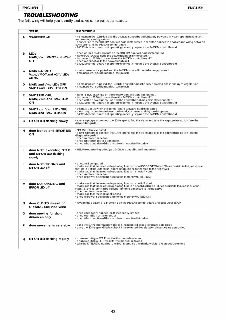
43
ENGLISH ENGLISH
SD-KEEPER off •no mains power supplied and the 940SDM control board is battery-powered in NIGHT operating function,and in energy saving statues.•connection to the 940SDM control board is interrupted: check the connection cables and wiring betweenSD-Keeper and the 940SDM control board•940SDM control board not operating correctly; replace the 940SDM control board
A
TROUBLESHOOTINGTROUBLESHOOTINGTROUBLESHOOTINGTROUBLESHOOTINGTROUBLESHOOTINGThe following will help you identify and solve some particular states.
LEDsMAIN, VACC, VMOT and +24VOFF
•check if the F2 5x20 T1A fuse on the 940SDM control board is interrupted•is the 5x20 T1A fuse inside the power supply unit interrupted?•Is connector J2 fitted correctly on the 940SDM control board?•check connection to the power supply unit•940SDM control board not operating correctly; replace the 940SDM control board
B
MAIN LED OFF;VACC, VMOT and +24V LEDsall ON
•mains power not supplied and the 940SDM control board is battery-powered•if mains power is being supplied, see point B
C
MAIN and VACC LEDs OFF;VMOT and +24V LEDs ON
•no mains power supplied, the 940SDM control board is battery-powered and in energy saving statues.•if mains power is being supplied, see point B
D
VMOT LED OFF;MAIN, VACC and +24V LEDsON
•is the F1 5x20 T6.3A fuse on the 940SDM control board interrupted?•Is connector J3 fitted correctly on the 940SDM control board?•check if the power supply unit and the control board are efficiently connected•940SDM control board not operating correctly; replace the 940SDM control board
E
VMOT and VACC LEDs OFF;MAIN and +24V LEDs ON
•this state occurs when the control board software is being updated•there may be condensation on the board; cut power and dry the dampness.•940SDM control board not operating correctly; replace the 940SDM control board
F
ERROR LED flashing slowly •alarm in progress: connect the SD-Keeper to find the alarm and take the appropriate action (see thediagnostics guide)
G
door locked and ERROR LEDON
•SETUP must be executed•alarm in progress: connect the SD-Keeper to find the alarm and take the appropriate action (see thediagnostics guide)•check motor connection•check motor encoder connection•check the condition of the encoder connection flat cable
H
door NOT executing SETUPand ERROR LED flashingslowly
•SETUP execution impeded (see 940SDM control board instructions)I
door NOT CLOSING andERROR LED off
•photocell/s engaged•make sure that the selected operating function is not DOOR OPEN (if no SD-Keeper is installed, make surethat input 8 of the J6 terminal board is not jumper connected to the negative)•make sure that the selected operating function is not MANUAL•check motor connection•check if power is being supplied to the motor (VMOT LED ON)
L
door NOT OPENING andERROR LED off
•make sure that the selected operating function is not MANUAL•make sure that the selected operating function is not NIGHT (if no SD-Keeper is installed, make sure thatinput 7 of the J6 terminal board is not jumper connected to the negative)•check motor connection•make sure that the lock is not locked•check if power is being supplied to the motor (VMOT LED ON)
M
door CLOSES instead ofOPENING and vice versa
•reverse the position of dip-switch 1 on the 940SDM control board and execute a SETUPN
door moving for shortdistances only
•check if encoder connector J4 is correctly inserted•check condition of the encoder•check the condition of the encoder connection flat cable
O
door movements very slow •using the SD-Keeper+Display, check if the selected speed levels are as required•using the SD-Keeper+Display, check if the selected deceleration distances are as required
P
ERROR LED flashing rapidly •door executing a SETUP; wait for the procedure to end•door executing a RESET; wait for the procedure to end•with the KIT ELASTIC installed, the door is resetting the elastic; wait for the procedure to end
Q
STATE SUGGESTION

Le descrizioni e le illustrazioni del presente manuale non sono impegnative. La FAAC si riserva il diritto,lasciando inalterate le caratteristiche essenziali dell’apparecchiatura, di apportare in qualunquemomento e senza impegnarsi ad aggiornare la presente pubblicazione, le modifiche che essa ritieneconvenienti per miglioramenti tecnici o per qualsiasi altra esigenza di carattere costruttivo o commer-ciale.
The descriptions and illustrations contained in the present manual are not binding. FAAC reserves theright, whilst leaving the main features of the equipments unaltered, to undertake any modifications itholds necessary for either technical or commercial reasons, at any time and without revising the presentpublication.
Les descriptions et les illustrations du présent manuel sont fournies à titre indicatif. FAAC se réserve le droitd’apporter à tout moment les modifications qu’elle jugera utiles sur ce produit tout en conservant lescaractéristiques essentielles, sans devoir pour autant mettre à jour cette publication.
Die Beschreibungen und Abbildungen in vorliegendem Handbuch sind unverbindlich. FAAC behältsich das Recht vor, ohne die wesentlichen Eigenschaften dieses Gerätes zu verändern und ohneVerbindlichkeiten in Bezug auf die Neufassung der vorliegenden Anleitungen, technisch bzw. konstruktiv/kommerziell bedingte Verbesserungen vorzunehmen.
Las descripciones y las ilustraciones de este manual no comportan compromiso alguno. FAAC sereserva el derecho, dejando inmutadas las características esenciales de los aparatos, de aportar, encualquier momento y sin comprometerse a poner al día la presente publicación, todas las modificacionesque considere oportunas para el perfeccionamiento técnico o para cualquier otro tipo de exigenciade carácter constructivo o comercial.
Timbro del Rivenditore:/Distributor’s Stamp:/Timbre de l’Agent:/ Fachhändlerstempel:/Sello del Revendedor:
FAAC S.p.A.Via Benini, 140069 Zola Predosa (BO) - ITALIATel.: 051/61724 - Fax: 051/758518www.faacgroup.com
FAAC per la natura• La presente istruzione è realizzata al 100% in carta riciclata.• Non disperdete nell'ambiente gli imballaggi dei componenti dell'automazione bensì selezionate
i vari materiali (es. cartone, polistirolo) secondo prescrizioni locali per lo smaltimento rifiuti e lenorme vigenti.
FAAC for the environment• The present manual is produced in 100% recycled paper• Respect the environment. Dispose of each type of product packaging material (card, polystyrene)
in accordance with the provisions for waste disposal as specified in the country of installation.
FAAC der Umwelt zuliebe• Vorliegende Anleitungen sind auf 100% Altpapier gedruckt.• Verpackungsstoffe der Antriebskomponenten (z.B. Pappe, Styropor) nach den einschlägigen
Normen der Abfallwirtschaft sortenrein sammeln.FAAC écologique• La présente notice a été réalisée 100% avec du papier recyclé.• Ne pas jeter dans la nature les emballages des composants de l’automatisme, mais sélectionner
les différents matériaux (ex.: carton, polystyrène) selon la législation locale pour l’élimination desdéchets et les normes en vigueur.
FAAC por la naturaleza.• El presente manual de instrucciones se ha realizado, al 100%, en papel reciclado.• Los materiales utilizados para el embalaje de las distintas partes del sistema automático (cartón,
poliestireno) no deben tirarse al medio ambiente, sino seleccionarse conforme a las prescripcioneslocales y las normas vigentes para el desecho de residuos sólidos.
7326
81 -
Re
v.A
para
la n
atur
alez
a10
0% p
apel
rec
icla
dois
t um
wel
tfreu
ndlic
h10
0% A
ltpap
ier
pour
la n
atur
epa
pier
rec
yclé
100
%fo
r na
ture
recy
cled
pap
er 1
00%
cart
a ric
icla
ta 1
00%
per
la n
atur
a

FAAC (UK) Limited, 6 Hamilton CloseHoundmills Estate, Basingstoke, RG21 6YTTelephone: 01256 318100Fax: 01256 318101Email: [email protected]: www.faac.co.uk
V5 01/07
Your authorised FAAC dealer
The descriptions and illustrations contained in this manual are not binding. FAAC reserve the right, whilst leaving the main features of the main equipment unaltered, to undertake any modifi cations it holds necessary for either technical or commercial reasons, at any time and without revising the present publication.
FAAC (UK) Limited, 6 Hamilton CloseHoundmills Estate, Basingstoke, RG21 6YTTelephone: 01256 318100Fax: 01256 318101Email: [email protected]: www.faac.co.uk
V5 01/07
Your authorised FAAC dealer
The descriptions and illustrations contained in this manual are not binding. FAAC reserve the right, whilst leaving the main features of the main equipment unaltered, to undertake any modifi cations it holds necessary for either technical or commercial reasons, at any time andwithout revising the present publication.
FAAC (UK) Limited, 6 Hamilton CloseHoundmills Estate, Basingstoke, RG21 6YTTelephone: 01256 318100Fax: 01256 318101Email: [email protected]: www.faac.co.uk
V5 01/07
Your authorised FAAC dealer
The descriptions and illustrations contained in this manual are not binding. FAAC reserve the right, whilst leaving the main features of the main equipment unaltered, to undertake any modifi cations it holds necessary for either technical or commercial reasons, at any time and without revising the present publication.
FAAC (UK) Limited, 6 Hamilton CloseHoundmills Estate, Basingstoke, RG21 6YTTelephone: 01256 318100Fax: 01256 318101Email: [email protected]: www.faac.co.uk
V5 01/07
Your authorised FAAC dealer
The descriptions and illustrations contained in this manual are not binding. FAAC reserve the right, whilst leaving the main features of the main equipment unaltered, to undertake any modifi cations it holds necessary for either technical or commercial reasons, at any time and without revising the present publication.