Embed Size (px)
Citation preview

INSTALLATION MANUAL
KRA 405BRADAR ALTIMETER
MANUAL NUMBER 006-10536-0010REVISION 10 OCTOBER, 2005
WARNINGThe enclosed technical data is eligible for export under License Designation NLR and is to be used solely by the individual/organization to whom it is addressed. Diversion contrary to U.S. law is prohibited.
COPYRIGHT NOTICE
©1997, 1999, 2001, 2003, 2005 Honeywell International Inc.
REPRODUCTION OF THIS PUBLICATION OR ANY PORTION THEREOF BY ANY MEANS WITHOUT THE EXPRESS WRITTEN PERMISSION OF HONEYWELL IS PROHIBITED, EXCEPT TO THE EXTENT REQUIRED FOR INSTALLATION OR MAINTENANCE OF THE RECIPIENT’S EQUIPMENT. FOR FURTHER INFORMATION CONTACT THE MANAGER, TECHNICAL PUBLICATIONS, HONEYWELL, ONE TECHNOLOGY CENTER, 23500 WEST 105th STREET OLATHE KS 66061 TELEPHONE: (913) 712-0400.

NKRA 405B RADAR ALTIMETER INSTALLATION MANUAL
REVISION HIGHLIGHTS
006-10536-0010 Rev. 10
Oct/2005
This is a full reprint of the KRA 405B Installation Manual. Discard the previous manual revision in its entirety. Specific changes to content are denoted by change bars.
Revision highlight(s) include the updating the environmental qualification forms to revision AF.
Page RH-1 006-10536-0010 Rev. 10 Oct/2005

NKRA 405B RADAR ALTIMETER INSTALLATION MANUAL
THIS PAGE IS RESERVED
Page RH-2 006-10536-0010 Rev. 10 Oct/2005

NKRA 405B RADAR ALTIMETER INSTALLATION MANUAL
TABLE OF CONTENTS
ITEM PAGE
SECTION IGENERAL INFORMATION
1.0 INTRODUCTION ............................................................... 1-1
1.1 DESCRIPTION OF EQUIPMENT ................................................... 1-2
1.2 ACRONYMS AND ABBREVIATIONS ................................................. 1-3
1.3 TECHNICAL CHARACTERISTICS .................................................. 1-4
A. KRA 405B RADAR ALTIMETER SYSTEM ............................................ 1-4
B. KRA 405B RECEIVER/TRANSMITTER TSO .......................................... 1-4
C. KRA 405B RECEIVER/TRANSMITTER .............................................. 1-4
D. KNI 415/416 INDICATOR ...................................................... 1-7
E. KA 54A ANTENNA ............................................................. 1-8
F. KA 54 ANTENNA (RETROFIT ONLY) .............................................. 1-9
1.4 UNITS AND ACCESSORIES SUPPLIED (KRA 405B SYSTEM COMPONENTS) ................ 1-9
A. RADAR ALTIMETER (Receiver/Transmitter) ..................................... 1-9
B. RADAR ALTIMETER INDICATOR - Honeywell KNI 415 or KNI 416 .................. 1-10
C. RADAR ALTIMETER ANTENNAS (2 each) ......................................... 1-10
D. KRA 405B INSTALLATION KIT ................................................. 1-10
E. KNI 415/416 INDICATOR INSTALLATION KIT .................................... 1-11
F. KA 54A RADAR ALTIMETER ANTENNA INSTALLATION KIT ........................... 1-11
1.5 ACCESSORIES REQUIRED BUT NOT SUPPLIED .....................................1-11
1.6 OPTIONAL ACCESSORIES RECOMMENDED BUT NOT SUPPLIED ......................... 1-12
A. CM 2000 CONFIGURATION MODULE KIT P/N 050-03380-0000. ...................... 1-12
B. KPA 900 CONFIGURATION MODULE PROGRAMMER KIT ............................... 1-13
1.7 LICENSE REQUIREMENTS ...................................................... 1-14
1.8 INSTRUCTIONS FOR CONTINUED AIRWORTHINESS .................................. 1-14
SECTION IIINSTALLATION
2.1 GENERAL INFORMATION ........................................................ 2-1
2.2 UNPACKING AND INSPECTING EQUIPMENT ......................................... 2-1
2.3 EQUIPMENT INSTALLATION ..................................................... 2-1
Page TC-1 006-10536-0010 Rev. 10 Oct/2005
NKRA 405B RADAR ALTIMETER INSTALLATION MANUAL
ITEM PAGE
2.4 CONFIGURABLE PARAMETERS .................................................... 2-2
A. ALTITUDE TRIP POINTS ....................................................... 2-2
B. ZERO FEET OFFSET ........................................................... 2-4
C. KPA 900 CONFIGURATION MODULE PROGRAMMER KIT ................................ 2-6
D. DH AUDIO OUTPUT ............................................................ 2-6
2.5 KRA 405B SYSTEM INSTALLATION ...............................................2-6
A. KRA 405B RECEIVER/TRANSMITTER .............................................. 2-6
B. KNI 415/416 INDICATOR ...................................................... 2-8
C. ANTENNAS ................................................................... 2-9
D. PLANNING THE ANTENNA INSTALLATION ......................................... 2-10
E. IMPLEMENTING THE ANTENNA INSTALLATION .....................................2-12
F. ANTENNA CABLES ............................................................ 2-13
G. WIRING HARNESS ............................................................ 2-14
H. CONFIGURATION MODULE INSTALLATION ......................................... 2-14
2.6 POST INSTALLATION ......................................................... 2-15
A. POST INSTALLATION CALIBRATION ............................................. 2-15
B. GENERAL ................................................................... 2-17
C. KRA 405B RADAR ALTIMETER POST INSTALLATION TEST PROCEDURE ................. 2-17
D. TEST PROCEDURE ............................................................ 2-20
2.7 REMOVAL AND REPLACEMENT ................................................... 2-22
A. KRA 405B RECEIVER/TRANSMITTER ............................................. 2-22
B. KNI 415/416 INDICATOR ..................................................... 2-23
C. ANTENNAS .................................................................. 2-24
2.8 HONEYWELL MAINTENANCE RECOMMENDATIONS .....................................2-24
SECTION IIIOPERATION
3.1 GENERAL .................................................................... 3-1
3.2 NORMAL OPERATION ........................................................... 3-2
A. PREFLIGHT .................................................................. 3-2
B. TAXI ....................................................................... 3-2
C. IN FLIGHT OPERATION ........................................................ 3-3
Page TC-2 006-10536-0010 Rev. 10 Oct/2005

NKRA 405B RADAR ALTIMETER INSTALLATION MANUAL
ITEM PAGE
D. APPROACH ................................................................... 3-3
E. PUSH-TO-TEST MODE .......................................................... 3-3
3.3 SELF-TEST DIAGNOSTICS ...................................................... 3-4
TSO APPENDIX
Page TC-3 006-10536-0010 Rev. 10 Oct/2005

NKRA 405B RADAR ALTIMETER INSTALLATION MANUAL
THIS PAGE IS RESERVED
Page TC-4 006-10536-0010 Rev. 10 Oct/2005
NKRA 405B RADAR ALTIMETER INSTALLATION MANUAL
ITEM PAGE
FIGURE 2-1 KRA 405B DEFAULT TRIP POINT SETTINGS .............................2-3FIGURE 2-2 KRA 405B TRIP POINT EDITING WINDOW ............................... 2-3FIGURE 2-3 KRA 405B ZERO POINT OFFSET ....................................... 2-5FIGURE 2-4 KRA 405B POST INSTALLATION CALIBRATION SWITCH ...................2-16FIGURE 2-5 KNI 415/416 INSTALLATION DRAWING ................................ 2-25FIGURE 2-6 KRA 405B INSTALLATION DRAWING ................................... 2-27FIGURE 2-7 DUAL RADAR ALTIMETER SYSTEM TYPICAL ANTENNA INSTALLATIONS ....... 2-29FIGURE 2-8 KA 54 ANTENNA OUTLINE AND MOUNTING DRAWING ...................... 2-33FIGURE 2-9 UBC TYPE AD 43013-1 AND COMANT TYPE 01-34-04531 ................. 2-35FIGURE 2-10 DORNE MARGOLIN TYPE DMPN 3-4/A ANTENNA .......................... 2-37FIGURE 2-11 KA 54A ANTENNA .................................................. 2-39FIGURE 2-12 HONEYWELL GT 7003586 (SENSOR SYSTEMS TYPE S67-2002-4 ANTENNA) ... 2-41FIGURE 2-13 TNC COAX/CONNECTOR ASSEMBLY (RG 393/U) .......................... 2-43FIGURE 2-14 CONNECTOR PIN LOCATIONS ......................................... 2-44FIGURE 2-15 KRA 405B TEST EQUIPMENT SETUP ................................... 2-45FIGURE 2-16 EXTERNAL SONALERT ............................................... 2-46FIGURE 2-17 KRA 405B RADAR ALTIMETER SYSTEM INTERCONNECT .................... 2-47FIGURE 2-18 CM 2000 CONFIGURATION MODULE MOUNTING DRAWING ...................2-49FIGURE 3-1 KNI 415 CONTROL FUNCTIONS ........................................ 3-5FIGURE 3-2 KNI 416 CONTROL FUNCTIONS ........................................ 3-6
Page TC-5 006-10536-0010 Rev. 10 Oct/2005

NKRA 405B RADAR ALTIMETER INSTALLATION MANUAL
THIS PAGE IS RESERVED
Page TC-6 006-10536-0010 Rev. 10 Oct/2005
NKRA 405B RADAR ALTIMETER INSTALLATION MANUAL
ITEM PAGE
TABLE 1-1 KNI 415/416 INDICATOR AVAILABILITY .............................. 1-10TABLE 1-2 CABLE INSTALLATIONS ............................................. 1-11TABLE 2-1 TSO CERTIFIED ANTENNAS ........................................... 2-9
Page TC-7 006-10536-0010 Rev. 10 Oct/2005

NKRA 405B RADAR ALTIMETER INSTALLATION MANUAL
THIS PAGE IS RESERVED
Page TC-8 006-10536-0010 Rev. 10 Oct/2005

NKRA 405B RADAR ALTIMETER INSTALLATION MANUAL
SECTION IGENERAL INFORMATION
1.0 INTRODUCTION
This manual contains information relative to the physical, mechanical, and electrical characteristics of the BENDIX/KING KRA 405B. Installation and operating procedures are also included. Information relative to the maintenance and procurement of replacement parts may be found in the KRA 405B Maintenance Manual Part Number 006-15536-00XX (XX = Highest Revision).
NOTE: The KRA 405B System consists of four modules: the Radar Altim-eter (Receiver/Transmitter), the Radar Altimeter Indicator, the Radar Altimeter Antennas (2 each), and the CM 2000 Configuration Module (optional). The system is positioned as a replacement for the KRA 405 Radar Altimeter System.
The preferred configurations utilize the following components:
COMPONENT UNIT PART NUMBER CHARACTERISTIC
RADAR ALTIMETER KRA 405B 066-01153-0101 STANDARD
KRA 405B 066-01153-0202 ARINC 552A
KRA 405B 066-01153-2001/-4001 ENHANCED DIGITAL AC-CURACY
CONTROLLER/DISPLAY KNI 415 066-3031-00 5 VOLT BLK
KNI 415 066-3031-01 28 VOLT BLK
KNI 415 066-3031-02 5 VOLT GRY
KNI 415 066-3031-03 28 VOLT GRY
KNI 415 066-3031-04 28 VOLT BLK NIGHT VI-SION
KNI 416 066-3044-00 5 VOLT BLK
KNI 416 066-3044-01 28 VOLT BLK
KNI 416 066-3044-02 5 VOLT GRY
KNI 416 066-3044-03 28 VOLT GRY
KNI 416 066-3044-04 28 VOLT BLK NIGHT VI-SION
ANTENNA KA 54A 071-1501-00 WHITE (2 EACH)
ANTENNA (OPTIONAL) KA 54A 071-01501-0100 BLACK (2 EACH)
CONFIGURATION MODULE CM 2000 071-00097-0100 OPTIONAL
Page 1-1 006-10536-0010 Rev. 10 Oct/2005

NKRA 405B RADAR ALTIMETER INSTALLATION MANUAL
Some part numbers may not be currently available. Consult the current Honeywell catalog or contact a Honeywell representative for equipment availability. The KRA 405B System also may consist of previously TSO certified components from the following list. However the use of any configurations other than the preferred configuration will result in reduced functionality of the system.
Upon use of the above antennas or any other configurations, the STC certification will be the sole responsibility of the customer and/or the installing agent. Please contact a field representative for additional information.
1.1 DESCRIPTION OF EQUIPMENT
The KRA 405B Radar Altimeter System provides the pilot with dependable, accurate AGL (altitude above ground level) information during the approach phase of a flight. The system has the capability of alerting the pilot when a predetermined altitude (decision height) is reached. The system also provides altitude information to the flight control system during the approach.
The KRA 405B Radar Altimeter (P/N 066-01153-0202), in addition to providing an ARINC 552A output for Auxiliary Out 2, has the ability to take a DH input from an EFIS or KNI 415/416 and generate an audio signal (refer to section 1.3. C. KRA 405B RECEIVER/TRANSMITTER for tone generator circuit specifications).
The KRA 405B Radar Altimeter (P/N 066-01153-2001/-4001) provides enhanced accuracy (± 2 feet) below 100 feet using the digital 429 Buss labels 164 and 165.
Both KRA 405B versions P/N 066-01153-0101 and P/N 066-01153-0202 with software 01/04, 02/04 or higher will not report negative values of altitude on the ARINC 429 digital bus unless expressly configured to do so. This feature is required for installations with Honeywell EFIS 40/50. One of these two unit versions (-0101 or -0202) must be used when interfacing the digital output of the KRA 405B to equipment which expect non-negative values.
The KRA 405B determines the altitude above ground level (AGL) by transmitting a signal to the ground then processing the reflected signal. The altimeter outputs the altitude information as analog voltages and in ARINC 429 digital format.
MODEL KA 54
DESCRIPTION RETROFIT ANTENNA
Page 1-2 006-10536-0010 Rev. 10 Oct/2005

NKRA 405B RADAR ALTIMETER INSTALLATION MANUAL
The KRA 405B Radar Altimeter System consists of the KRA 405B Receiver/ Transmitter, the KNI 415 or KNI 416 Indicator, and two (2) KA 54A Antennas. The entire system is solid state except for a servo mechanism and relay in the Indicator.
The KRA 405B Radar Altimeter replaces the KRA 405 altimeter. The KRA 405B is electrically compatible with the same indicators and antennas as the KRA 405.
NOTE: The connectors for KRA 405 and KRA 405B are not compatible.
1.2 ACRONYMS AND ABBREVIATIONS
ACRONYM MEANING
AGL Above Ground Level
ARINC Aeronautical Radio Incorporated
EUROCAE The European Organization for Civil Aviation Electronics
FAA Federal Aviation Administration
FCC Federal Communications Commission
FTZ Fernmeldetechischeszentralamt (German)
Hz Hertz
IF Intermediate Frequency
kHz kilohertz
GHz Gigahertz
MHz Megahertz
PEO Precision Equipment Output
P/N Part Number
RTCA Requirements and Technical Concepts for Aviation
R/T Receiver/Transmitter
TSO Technical Standing Order
VSWR Voltage Standing Wave Ratio
XX Part numbers ending in XX denotes the highest revision available (Example: 006-10536-00XX)
Page 1-3 006-10536-0010 Rev. 10 Oct/2005

NKRA 405B RADAR ALTIMETER INSTALLATION MANUAL
1.3 TECHNICAL CHARACTERISTICS
A. KRA 405B RADAR ALTIMETER SYSTEM
B. KRA 405B RECEIVER/TRANSMITTER TSO
C. KRA 405B RECEIVER/TRANSMITTER
SYSTEM ALTITUDE ACCURACY: ± 5 ft (1.5 m) or ± 5% (whichever is greater) at 0 to 500 feet and ± 7% at 500 to 2,500 feet
SYSTEM ANTENNA CABLES (2 Required): Length: See 1.5 ACCESSORIES REQUIRED BUT NOT SUPPLIED Cable Type: See TABLE 1-2 CABLE INSTALLATIONSSYSTEM POWER REQUIREMENTS: 27.5 Vdc ± 20% at 2 Amperes maximumSYSTEM WEIGHT (less cables): 5.1 lbs (2.31 kg)
TSO COMPLIANCE: C87/ETSO-2C87 (See TSO APPENDIX)
ALTITUDE: 55,000 ft (16,764 m)
OPERATIONAL TEMPERATURE RANGE: -55° C to +70° CNON TSO’D FUNCTIONS NONE
PHYSICAL CHARACTERISTICS:
Length: Width: Height:
See FIGURE 2-6 KRA 405B INSTALLATION DRAWING
WEIGHT: KRA 405B With Mtg rack (optional)
See FIGURE 2-6 KRA 405B INSTALLATION DRAWING
POWER REQUIREMENTS: Nominal Current Maximum Current
27.5 Vdc ± 20% at 850 mA18 Vdc @ 1.2 Amperes (emergency)
ALTITUDE RANGE: Tracked: -20 to 2,500 feet (-6.1 to 762.0 m)
ALTITUDE TRIPS (selectable): Adjustment Range #1, 2, and 3: (Con-figuration Module Programmable) Factory Settings:
0-2500 feet (0-762.00 m)
Trip #1 200 feet (60.90 m)Trip #2 500 feet (152.40 m)Trip #3 1200 feet (365.76 m)
ALTITUDE ACCURACY:066-01153-0101,-0202,-2001/-4001(All Analog and Digital Altitude Outputs except 066-01153-2001/-4001 Digital Outputs)
3 ft (0.91 m) or ± 3% (whichever is greater) at 0 to 500 feet and ± 5% at 500 to 2,500 feet
ALTITUDE ACCURACY:066-01153-2001/-4001ARINC 429 Outputs Labels 164 and 165
± 2 ft (0.61 m) below 100 feet,± 3% at 100 feet to 500 feet, and± 5% at 500 to 2,500 feet
Page 1-4 006-10536-0010 Rev. 10 Oct/2005

NKRA 405B RADAR ALTIMETER INSTALLATION MANUAL
C. KRA 405B RECEIVER/TRANSMITTER (cont.)
ALTITUDE OUTPUT: Slope: Precision Equipment: -20 to 2,500 ft (-6.1 to 762.0 m) -10 mV/ft (32.81 mV/m); Zero
ft = 0.000 volts
Auxiliary Out #1: -20 to 500 feet (-6.1 to 152.4 m) +20 mV/ft (+65.62 mV/m); 500 to 2,500 feet (152.4 to 762 m) +3 mV/ft (9.84 mV/m); Zero ft = +0.400 volts
Auxiliary Out #2: (-0101, -2001/-4001)
-20 to 2,500 feet (-6.1 to 762.0 m) -4 mV/ft (13.12 mV/m); Zero feet = 0.000 volts
Auxiliary Out #2: (-0202)
-20 to 480 feet (-6.1 to 146.3 m) +20 mV/ft (+65.62 mV/m); 480 to 2,500 feet (146.3 to 762 m) 10 x logn [e(h+20)/500](10 x logn [e(h+6.1/152.4)]m); Zero ft = +0.400 volts
Analog Altitude: -20 to 500 feet (-6.1 to 152.4 m) +20 mV/ft (+65.62 mV/m); 500 to 2,500 feet (152.4 to 762 m) +3 mV/ft (9.84 mV/m); Zero ft = +0.400 volts
Arinc 429 Out: Shall meet all ARINC 429 electricalspecifications.
The following are serial digital outputs from the KRA 405B:
LABEL INFORMATION CONTAINED IN LABEL FORMAT SPEED
164 Radio Height BNR Low Speed
165 Radio Height BCD Low Speed
371 GA Equipment Code BCD Low Speed
377 Equipment Identifier Word BCD Low Speed
Page 1-5 006-10536-0010 Rev. 10 Oct/2005

NKRA 405B RADAR ALTIMETER INSTALLATION MANUAL
C. KRA 405B RECEIVER/TRANSMITTER (cont.)
Load Capability: 4 loads, @ 2 kΩ per loadOff Scale Voltage:
Precision Equipment Output: -28.0 ± 1.5 Vdc Auxiliary Out #1: +17.3 ± 0.5 Vdc Auxiliary Out #2: -11.2 ± 0.6 Vdc (-0101) Auxiliary Out #2: 27.5 ± 1.5 Vdc (-0202)Time Constant:
Precision Equipment Output: 0.1 second maximum
TRANSMITTER OUTPUT:
Power: 160 mW nominal, FMCW
Center Frequency: 4300 ± 15 MHz Modulation Frequency:
Primary: 100 Hz nominal
Secondary: 105 Hz nominal (in dual installation)
TRANSMITTER OUTPUT: (cont.)
FM Deviation P-P: 100 MHz
Type of Service: Continuous
WARNING SYSTEM:
FCS Warn:
Normal Operation: +18 to +32 Vdc at less than 250 mA
Warn Condition: Less than 10 μA Altimeter Valid:
Normal Operation: +18 to +32 Vdc at less than 250 mA
Warn Condition: Less than 10 μA Rad_Alt Valid:
Normal Operation: +18 to +32 Vdc at less than 250 mA
Warn Condition: Less than 10 μAALTITUDE TRIPS:
Tripped (Locked R/T): +0.5 Vdc maximum at less than 250 mA
Untripped (Unlocked R/T): 10 μA maximum at less than +30 Vdc
TONE GENERATOR CIRCUIT:
DH Tone Enable Active Level: Low: < 3.5 Vdc
Inactive Level: High: > 17 Vdc
Tone Active Time: 2.5 seconds ± .5 seconds Output Frequency: 587 HZ ± 20 Hz (music tone D) Output Level (-0202): 30mW ± 10 mW into a 500 Ω load Noise Level: 60 dB min below rated level
Page 1-6 006-10536-0010 Rev. 10 Oct/2005
NKRA 405B RADAR ALTIMETER INSTALLATION MANUAL
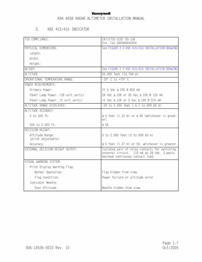
D. KNI 415/416 INDICATOR
TSO COMPLIANCE: C87/ETSO-2C87 DO-138Env. Cat GAPAAAXXXXXX
PHYSICAL DIMENSIONS: See FIGURE 2-5 KNI 415/416 INSTALLATION DRAWING
Length:
Width:
Height:
WEIGHT: See FIGURE 2-5 KNI 415/416 INSTALLATION DRAWING
ALTITUDE: 55,000 feet (16,764 m)
OPERATIONAL TEMPERATURE RANGE: -20° C to +70° CPOWER REQUIREMENTS:
Primary Power: 27.5 Vdc ± 20% @ 850 mA Panel Lamp Power: (28 volt units) 28 Vdc ± 10% or 26 Vac ± 10% @ 120 mA Panel Lamp Power: (5 volt units) +5 Vdc ± 10% or 5 Vac ± 10% @ 575 mAALTITUDE RANGE DISPLAYED: -20 to 2,000 feet (-6.1 to 609.60 m)
ALTITUDE ACCURACY:
0 to 500 ft: ± 4 feet (1.22 m) or ± 4% (whichever is great-er)
500 to 2,000 ft: ± 5%DECISION HEIGHT:
Altitude Range: (pilot adjustable)
0 to 2,000 feet (0 to 609.60 m)
Accuracy: ± 5 feet (1.27 m) or 5%, whichever is greaterEXTERNAL DECISION HEIGHT OUTPUT: Isolated pair of relay contacts for switching
external circuit. 110 mA at 28 Vdc, 3 watts maximum continuous contact load.
VISUAL WARNING SYSTEM:
Pilot Display Warning Flag:
Normal Operation: Flag hidden from view
Flag Condition: Power failure or altitude error
Indicator Needle:
Over Altitude: Needle hidden from view
Page 1-7 006-10536-0010 Rev. 10 Oct/2005

NKRA 405B RADAR ALTIMETER INSTALLATION MANUAL
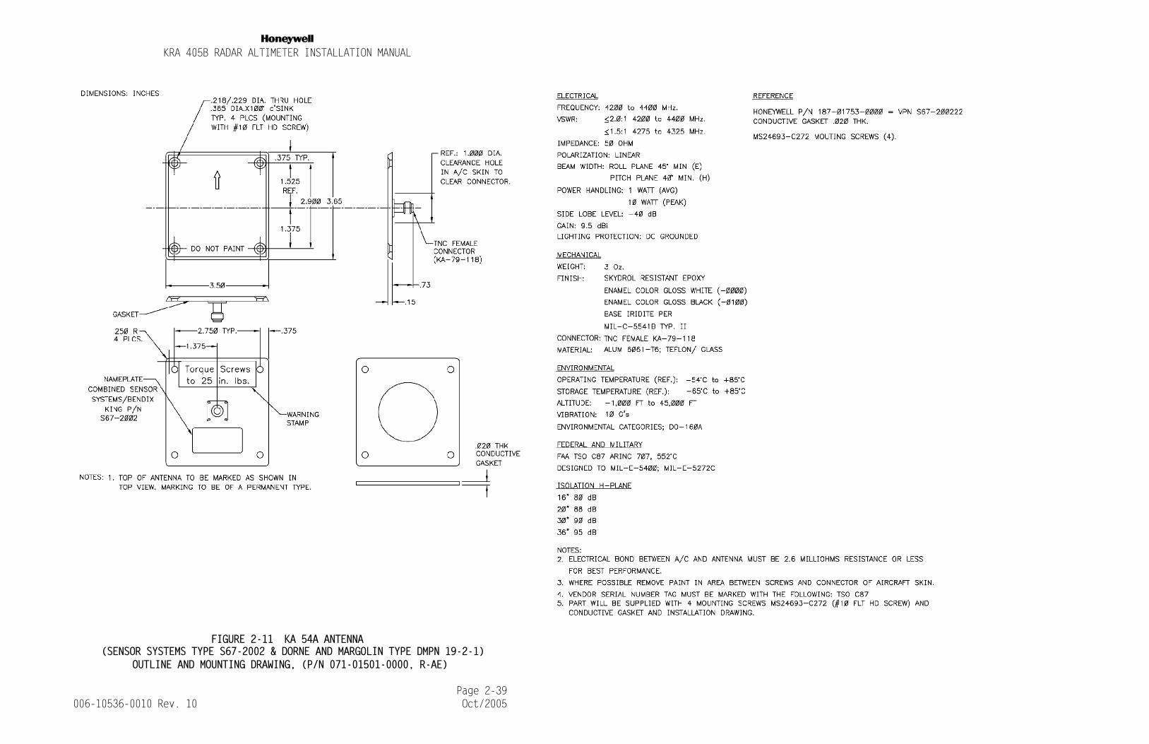
E. KA 54A ANTENNA
TSO COMPLIANCE: C87/ETSO-2C87 DO-160AEnv. Cat. D2AJXWFD
PHYSICAL CHARACTERISTICS: See FIGURE 2-11 KA 54A ANTENNA
Length:
Width:
Height:
WEIGHT: (2 required) See FIGURE 2-11 KA 54A ANTENNA
ALTITUDE: 60,000 ft (18,281 m)
OPERATIONAL TEMPERATURE RANGE: -54° C TO +85° CBEAMWIDTH:
E-Plane: 45° min. H-Plane: 40° min.SIDELOBES: Greater than -40 dB down
VSWR: 4240 - 4360 MHz: 1.5:1 Maximum
GAIN: 10 dBi (above isotopic)
POLARIZATION: Linear
POWER HANDLING: 1 watt average, 10 watts peak
CROSS COUPLING: 20 in spacing - 88 dB max36 in spacing - 95 dB max
INPUT IMPEDANCE: 50 ohms nominal
Page 1-8 006-10536-0010 Rev. 10 Oct/2005

NKRA 405B RADAR ALTIMETER INSTALLATION MANUAL
F. KA 54 ANTENNA (RETROFIT ONLY)
1.4 UNITS AND ACCESSORIES SUPPLIED (KRA 405B SYSTEM COMPONENTS)
NOTE: Some part numbers may not be currently available. Consult the current Honeywell catalog or contact a Honeywell representative for equipment availability.
A. RADAR ALTIMETER (Receiver/Transmitter)
Honeywell KRA 405B, P/N 066-01153-0101 (Standard)
Honeywell KRA 405B, P/N 066-01153-0202 (ARINC 552A compatible)
Honeywell KRA 405B, P/N 066-01153-2001/-4001 (Enhanced accuracybelow 100 feet).
TSO COMPLIANCE: C87/ETSO-2C87 DO-138Env. Cat. AAAAAX
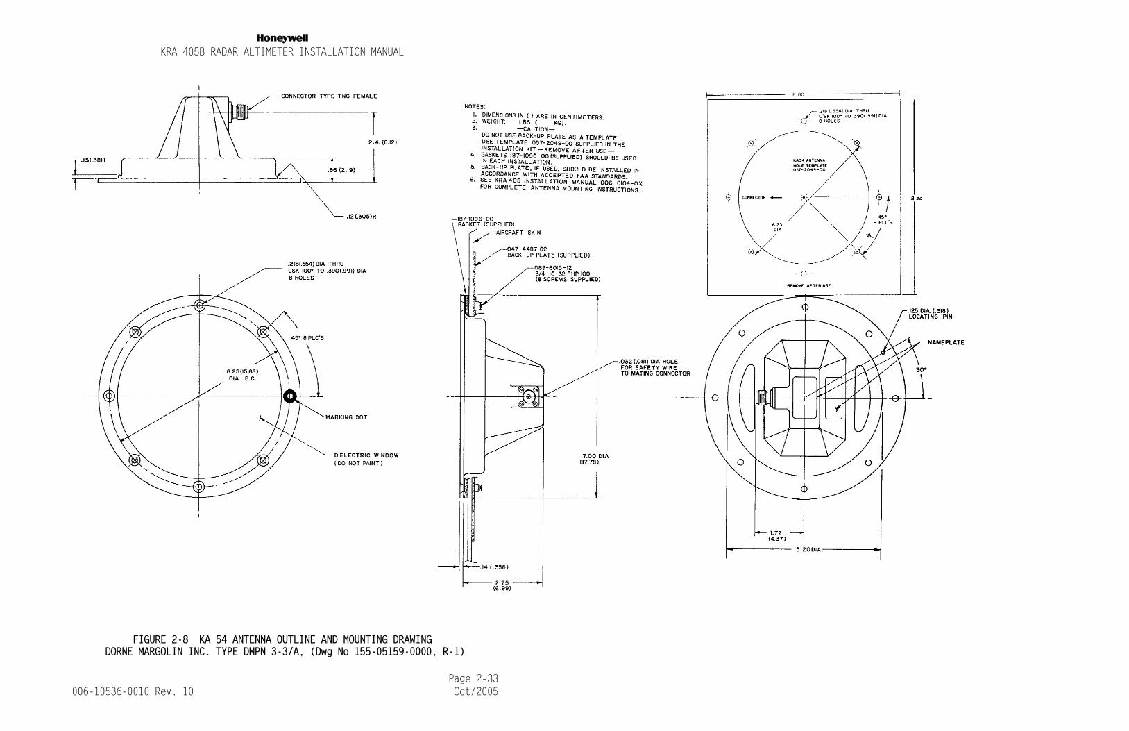
PHYSICAL CHARACTERISTICS: See FIGURE 2-8 KA 54 ANTENNA OUTLINE AND MOUNT-ING DRAWING
Length:
Width:
Height:
WEIGHT: (2 required) See FIGURE 2-8 KA 54 ANTENNA OUTLINE AND MOUNT-ING DRAWING
ALTITUDE: 55,000 feet (16,764 m)
OPERATIONAL TEMPERATURE RANGE: -54° C to +71° CBEAMWIDTH:
E-Plane: 50° ± 5° H-Plane: 40° ± 4°SIDELOBES: Greater than 25 dB down
VSWR: 4240 - 4360 MHz: 1.3:1 Maximum
GAIN: 11.5 dBi (above isotopic)
POLARIZATION: Linear
POWER HANDLING: 100 watts average, 1 kW peak
CROSS COUPLING: 20 in spacing - 80 dB max
36 in spacing - 95 dB max
INPUT IMPEDANCE: 50 ohms nominal
Page 1-9 006-10536-0010 Rev. 10 Oct/2005

NKRA 405B RADAR ALTIMETER INSTALLATION MANUAL
B. RADAR ALTIMETER INDICATOR - Honeywell KNI 415 or KNI 416
TABLE 1-1 KNI 415/416 INDICATOR AVAILABILITY
C. RADAR ALTIMETER ANTENNAS (2 each)
Honeywell KA 54A, Part Number 071-1501-00 (White) Part Number 071-01501-0100 (Black)
Gaskets are included with a new antenna. They may be ordered separately as P/N 187-01753-0000.
NOTE: The KA 54 Radar Altimeter Antenna is compatible with the KRA 405B and may be used in retrofit situations. However, this antenna is no longer available from the factory.
D. KRA 405B INSTALLATION KIT
P/N 050-03365-00XX which includes the following:
UNIT PART NUMBER FACEPLATE PANEL LIGHTING
KNI 415 066-3031-00 BLACK 5 VOLT
KNI 415 066-3031-01 BLACK 28 VOLT
KNI 415 066-3031-02 GRAY 5 VOLT
KNI 415 066-3031-03 GRAY 28 VOLT
KNI 415 066-3031-04 BLACK NIGHT VISION
KNI 416 066-3044-00 BLACK 5 VOLT
KNI 416 066-3044-01 BLACK 28 VOLT
KNI 416 066-3044-02 GRAY 5 VOLT
KNI 416 066-3044-03 GRAY 28 VOLT
KNI 416 066-3044-04 BLACK NIGHT VISION
PART NUMBER DESCRIPTION UM -00 -01 -02 -03 VENDOR PART NUMBER
030-02077-0000 41 Pin Conn Solder EA 1 1 0 0 CANNON KPT06B2041S
030-02077-0004 41 Pin Conn Crimp EA 0 0 1 1 CANNON KPSE06F20-41S
057-05944-0017 TSO KIT LABEL EA 1 0 0 0 N.A.
057-05944-0018 TSO KIT LABEL EA 0 1 0 0 N.A.
057-05944-0019 TSO KIT LABEL EA 0 0 1 0 N.A.
057-05944-0020 TSO KIT LABEL EA 0 0 0 1 N.A.
071-04003-0000 Mounting Rack EA 1 0 1 0
Page 1-10 006-10536-0010 Rev. 10 Oct/2005

NKRA 405B RADAR ALTIMETER INSTALLATION MANUAL
E. KNI 415/416 INDICATOR INSTALLATION KIT
P/N 050-01401-0002 which includes the following:
F. KA 54A RADAR ALTIMETER ANTENNA INSTALLATION KIT
P/N 050-02960-0000 which includes the following:
*See TABLE 1-2 CABLE INSTALLATIONS for alternate cable installations.
1.5 ACCESSORIES REQUIRED BUT NOT SUPPLIED
A. RG 393 Cable (preferred cable) Part Number 024-00075-0000 (seeTABLE 1-2 CABLE INSTALLATIONS for minimum and maximum lengths).
B. For other cable installations, see TABLE 1-2 CABLE INSTALLATIONS.
TABLE 1-2 CABLE INSTALLATIONS
PART NUMBER DESCRIPTION UM -02 VENDOR PART NUMBER
030-02210-0012 Connector EA 1 ITT CANNON KPS306F14-19SY
057-02029-0008 Connector Label EA 1
057-02029-0009 Connector Label EA 1
073-00044-0001 Plate, Mooring EA 1
073-00045-0000 Plate, Adapter Blk EA 1
073-00045-0001 Plate, Adapter Gry EA 1
089-05115-0012 FHP 6-32x3/4, Blk Scr EA 4
089-06461-0012 FHP 6-32x3/4, Gry Scr EA 4
PART NUMBER DESCRIPTION UM QTY VENDOR PART NUMBER
030-00108-0000 Conn RG 214-TNC EA 4 TED 5-10-43
Cable Type Part Number Attenuation/ Min total Max Total Min Bend
100 feet(dB) Install Install Radius
Length (ft) Length (ft) (in)
RG 393 024-00075-0000 18.75 24.5 45.3 5.8
RG 142 024-00002-0000 32.40 25.2 26.2 2.9
ECS 311601 024-00072-0000 18.5 29.0 45.9 3.5
ECS 311201 024-00071-0000 13.41 28.6 63.4 4.8
PIC: S44193 024-00077-0001 25.16 24.7 48.6 1.0
PIC: S67163 N/A 16 28.4 66.4 1.2
PIC: S33141 N/A 14.5 28.4 58.6 1.4
Page 1-11 006-10536-0010 Rev. 10 Oct/2005

NKRA 405B RADAR ALTIMETER INSTALLATION MANUAL
TED = TED Manufacturing CorporationECS = Electronic Cable Specialists, Inc.PIC = PIC Wire And Cable
TABLE 1-2 CABLE INSTALLATIONS
C. To allow for a valid on-ground calibration, the total installed ca-ble length plus twice the antenna height above ground must not ex-ceed 200 feet. This will only be a practical consideration for an-tennas mounted above 30 feet.
1.6 OPTIONAL ACCESSORIES RECOMMENDED BUT NOT SUPPLIED
A. CM 2000 CONFIGURATION MODULE KIT P/N 050-03380-0000.
CONNECTOR, STRAIGHT TNC CONNECTOR, RIGHT ANGLE TNC
Cable Cable Honeywell Vendor Honeywell Vendor
Type Part No. Part No. Part No. Part No. Part No.
RG 393 024-00075-0000 030-00108-0004 TED: 5-10-43-2 N/A TED: 5-30-14-1
RG 142 024-00002-0000 030-00134-0000 TED: 5-10-30 030-00134-0001 TED: 5-30-102
ECS 311601 024-00072-0000 N/A ECS: CTS 922 N/A ECS: CTR 922
ECS 311201 024-00071-0000 N/A ECS: CTS 122 N/A ECS: CTR 122
Cable Type CONNECTOR,STRAIGHT TNC
CONNECTOR,RIGHT ANGLE TNC
CONNECTOR,75 DEG. ANGLE TNC
PIC: S44193 PIC: 190108 PIC: 190109 PIC: 190131
PIC: S67163 PIC: 190508 PIC: 190509 PIC: 190531
PIC: S33141 PIC: 190308 PIC: 190309 PIC: 190331
PART NUMBER DESCRIPTION UM QTY VENDOR PART NUMBER
030-01157-0011 SOCKET CRIMP 20G EA 10 POSITRONIC FC6020D-14
030-01171-0000 CONN SUB-D HSG 9S EA 1 POSITRONIC RD09F00000-782.0
030-02351-0000 HOOD AND LEVER ASSY EA 1 POSITRONIC D9000JVL0-476
071-00097-0100 CM 2000 CONFIG MOD EA 1 HONEYWELL
155-06016-0000 INSTALL DWG. RF 1 N.A.
Page 1-12 006-10536-0010 Rev. 10 Oct/2005

NKRA 405B RADAR ALTIMETER INSTALLATION MANUAL
The CM 2000 allows the KRA 405B to operate with custom altitude trip points (rather than the factory preset values) and allows for an offset to the zero foot readout. Refer to section 2.4 CONFIGURABLE PARAMETERS to determine if the module is required for a particular installation.
B. KPA 900 CONFIGURATION MODULE PROGRAMMER KIT
The KPA 900 Configuration Module Programmer Kit is required to program the CM 2000 Configuration Module. Prior to the installation of the CM 2000, it must be programmed to store the custom specifications. Refer to the KPA 900 Programmer Operator’s Guide for complete instructions.
The KPA 900 is not part of the installation but rather a piece of equipment retained by the installer. If the installer does not have access to a KPA 900 with current software and the CM 2000 is required, order P/N 050-03311-0002 which contains the items listed below.
XX=Highest Revision
NOTE: For CM 2000 Configuration Modules used in ART 2000 Weather Radar and KRA 405B Radar Altimeter Installations and CM 2000 configuration modules that have never been pro-grammed or may have a default program for a different unit, a “write to” initialization must be performed be-fore writing the parameters required for the installation into the CM 2000 configuration module. From the File menu, load the default RDR 2000 or KRA 405B file into memory and perform a “write to” from the hardware menu. This will ensure that a correct default program, without errors, is present. The default program can then be modified from View in the memory menu. Refer to sections 1.4.2.1, 1.4.2.2, and 1.4.2.3 of the KPA 900 operators guide (006-05392-00XX).
PART NUMBER DESCRIPTION UM QTY VENDOR PART NUMBER
006-05392-00XX Operator’s Guide EA 1 Honeywell
050-03281-0000 KPA 900 Programmer EA 1 Honeywell
222-00366-0XXX Software Disc EA 1 Honeywell
Page 1-13 006-10536-0010 Rev. 10 Oct/2005
NKRA 405B RADAR ALTIMETER INSTALLATION MANUAL
1.7 LICENSE REQUIREMENTS
The transmitter, as installed in the aircraft, requires an Aircraft Radio Station License. This license is obtained by filing FCC Form 404. The KRA 405B may be operated for up to 30 days without a station license, after filing the FCC Form 404 and while awaiting the receipt of the station license, if a copy of the FCC Form 404 is kept in the aircraft.
This equipment has been type accepted by the FCC and entered on their list of type accepted equipment as Honeywell KRA 405B and must be identified as Honeywell KRA 405B on your FCC Form 404, Aircraft Radio Station License Application.
1.8 INSTRUCTIONS FOR CONTINUED AIRWORTHINESS
The instructions for continued airworthiness given in the TC or STC approvals for this product supplements or supersedes the instructions for continued airworthiness in this manual.
Most Honeywell products are designed and manufactured to allow “on condition maintenance”. On condition maintenance is described as follows:
There are no periodic service requirements necessary to maintain continued airworthiness. No maintenance is required until the equipment does not perform its intended function. When service is required, a complete performance test should be accomplished following any repair action. Consult the appropriate unit Maintenance/Overhaul Manual for complete performance test information.
14 CFR Part 25.1529 Instructions for Continued Airworthiness is met per the following instructions:
A. The removal of the KRA 405B is on the condition of failure. There is no required maintenance.
Page 1-14 006-10536-0010 Rev. 10 Oct/2005

NKRA 405B RADAR ALTIMETER INSTALLATION MANUAL
SECTION IIINSTALLATION
2.1 GENERAL INFORMATION
This section contains general suggestions and information to consider before installation of the KRA 405B. Close adherence to these suggestions will assure optimum performance from the equipment.
The conditions and tests required for the TSO and MOPS approval of this article are minimum performance standards. It is the responsibility of those installing this article either on or with a specified type or class of aircraft to determine that the aircraft installation conditions are within the TSO and MOPS standards. These articles must have separate approval for installation in an aircraft. Any features in this equipment outside the requirements of this applicable TSO and MOPS must be evaluated and approved as part of the installation approval. The article may be installed only if performed under 14 CFR part 43 or the applicable airworthiness requirements.
The unit may be installed only if further evaluation by the applicant documents an acceptable installation and is approved by the Administrator.
2.2 UNPACKING AND INSPECTING EQUIPMENT
Exercise extreme care when unpacking the equipment. Make a visual inspection of the unit for evidence of damage incurred during shipment. If a claim for damage is to be made, save the shipping container to substantiate the claim. The claim should be promptly filed with the transportation company.
It would be advisable to retain the container and packaging material after all equipment has been removed in the event that equipment storage or reshipment should become necessary.
2.3 EQUIPMENT INSTALLATION
The KRA 405B should be installed in accordance with standards established by the customer’s installing agency, and existing conditions as to unit location and type of installation. However, the following suggestions should be considered before installing the system. Close adherence to these suggestions will assure a more satisfactory performance from the equipment.
The locations chosen for units of the KRA 405B Radar System and the methods of installation will vary with each particular type of aircraft. The units should be installed in a convenient location for ease of operation and accessibility for inspection and maintenance.
Page 2-1 006-10536-0010 Rev. 10 Oct/2005
NKRA 405B RADAR ALTIMETER INSTALLATION MANUAL
The installing agency will supply and fabricate all external cables. The connectors required for RG 393 (the preferred cable) are supplied by Honeywell. Installation kits are also available. Consult 1.4 UNITS AND ACCESSORIES SUPPLIED (KRA 405B SYSTEM COMPONENTS) as required.
The greatest single contributor to increased reliability of all modern day avionics is to limit the maximum operating temperature of the individual units whether panel mounted or remote mounted. While modern day individual circuit designs consume much less electrical energy, watts per cubic inch dissipated within the avionics unit remains much the same due to the high density packaging techniques utilized. Consequently, the importance of providing cooling to the avionics stack is still with us today.
While each individual unit may or may not require forced air cooling, the combined heat load of several units operating in a typical avionics location will significantly degrade the reliability of the avionics if provisions for cooling are not incorporated in the initial installation. Failure to provide cooling to the equipment will lead to increased avionics maintenance costs and may also void the Honeywell warranty.
2.4 CONFIGURABLE PARAMETERS
The installer may alter some of the operational characteristics of the KRA 405B by installing a CM 2000 Configuration Module that has been programmed with customized preferences. These characteristics are the threshold altitudes for the three Altitude Trip Points and a selectable offset to be applied to all altitude outputs. If these parameters are inconsequential to the installation or the factory presets are acceptable, the CM 2000 should not be installed.
A. ALTITUDE TRIP POINTS
The KRA 405B provides three discrete outputs called Altitude Trip Point #1, Altitude Trip Point #2, and Altitude Trip Point.#3. The KRA 405B asserts the discrete when operating at an altitude below the configured trip point. The factory settings are: Altitude Trip Point #1 at 200 feet, Altitude Trip Point #2 at 500 feet, and Altitude Trip Point #3 at 1200 feet. If any other altitude is desired, a programmed configuration module must be installed with the KRA 405B.
Refer to the KPA 900 Operators Guide P/N 006-05392-OOXX for instructions to set up the programmer, invoke the program, and select the KRA 405B database. Select the Memory then the View options to display the default configuration. A screen similar to the following figure should be displayed.
Page 2-2 006-10536-0010 Rev. 10 Oct/2005

NKRA 405B RADAR ALTIMETER INSTALLATION MANUAL
Use the cursor keys or the mouse to move the highlight bar to the parameter that is to be adjusted.
FIGURE 2-1 KRA 405B DEFAULT TRIP POINT SETTINGS
Press the <Enter> key to display the Editing Window for the selected Trip Point. The window should be similar to the following figure.
FIGURE 2-2 KRA 405B TRIP POINT EDITING WINDOW
Enter an integer value between 0 and 2500 at the blinking cursor. Press the <Enter key> to accept the value.
Page 2-3 006-10536-0010 Rev. 10 Oct/2005

NKRA 405B RADAR ALTIMETER INSTALLATION MANUAL
The Editing window will be removed and the Memory Definitions window will again be displayed, to allow further changes, and the Main screen will display a message describing the changed parameter.
After completing the all changes to the settings, refer to the KPA 900 Operators Guide P/N 006-05392-00XX for instructions to complete the programming of the Configuration Module.
Honeywell recommends that the programmed module be verified before installation. Exit the KPA 900 program, re-invoke it, read the programmed module, and verify the correctness of the settings. This step will ensure that the programming operation was successful.
B. ZERO FEET OFFSET
The KRA 405B Receiver/Transmitter DOES NOT require an Aircraft Installation Delay (AID). The KRA 405B R/T has provisions to calibrate to zero feet during the installation. After this calibration, the KRA 405B will provide a radar altitude of basically zero feet (see note below) when the aircraft is taxiing or stationary on the ground.
NOTE: All versions of the KRA 405B with 01/03 or 02/03 software and -2001/-4001 version units with 01/03 or higher soft-ware may provide slight negative values of altitude when the aircraft is taxiing or at rest. This is normal oper-ation as the altitude calculation may vary around zero at plus and minus the system accuracy. All other unit and software configurations will "clamp" negative calculation results to zero feet, and never go negative. The config-uration module supplied offset is applied to the altitude data after the "clamp", so all unit configurations have the capability to produce negative results. The Honeywell EFIS 40 and EFIS 50 systems (and possibly other systems) will not display negative altitudes re-ceived on the digital bus. When the Honeywell EFIS detects a negative altitude value, it "declutters" or blanks the altitude information from the displays. The EFIS will also rebroadcast incorrect Radio Altitude information on the general-purpose bus.All versions of units with 01/03 or 02/03 software and -2001/-4001 version units with 01/03 or higher software must not interface to the EFIS 40 or EFIS 50 systems via the ARINC 429 bus. All flavors and software versions of he KRA 405B must not be configured with a zero foot offset when interfacing the EFIS via the digital bus. Interfaces via any of the analog outputs will function correctly.
Page 2-4 006-10536-0010 Rev. 10 Oct/2005
NKRA 405B RADAR ALTIMETER INSTALLATION MANUAL
The KRA 405B has provisions to allow some flexibility in the altitude at which zero feet is displayed. This deviation would be useful for installations where a zero foot reading is desired before the landing gear compresses or when the antennas are mounted significantly forward of the main gear. This capability is provided by adjusting the "Zero Foot Offset" parameter in the configuration module. If the installation is acceptable with zero feet displayed at rest, either do not install the configuration module or keep the default (0 feet) value for the Zero Foot Offset.
The Zero Feet Offset has the following limitations.
1. Zero Feet Offset must be a positive value
2. Zero Feet Offset must be less than 200 feet. Note that alti-tude values less than -20 feet shall be reported as -20 feet.
3. Zero Feet Offset must be in whole feet values.
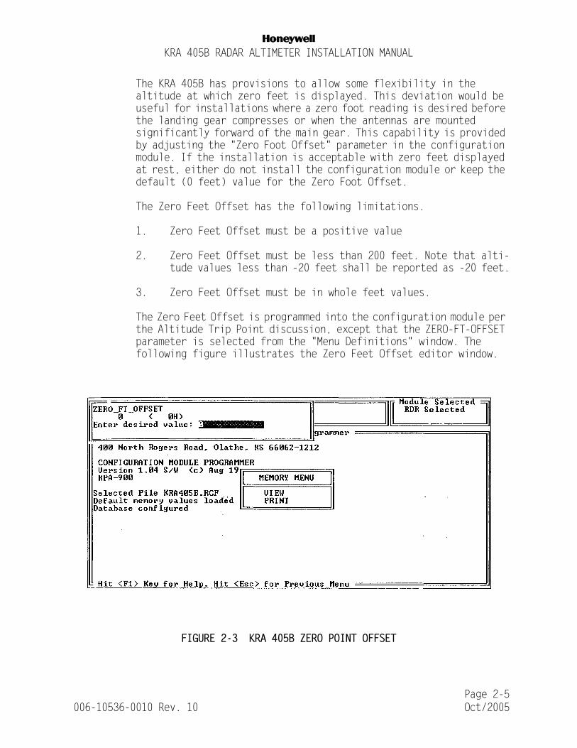
The Zero Feet Offset is programmed into the configuration module per the Altitude Trip Point discussion, except that the ZERO-FT-OFFSET parameter is selected from the "Menu Definitions" window. The following figure illustrates the Zero Feet Offset editor window.
FIGURE 2-3 KRA 405B ZERO POINT OFFSET
Page 2-5 006-10536-0010 Rev. 10 Oct/2005

NKRA 405B RADAR ALTIMETER INSTALLATION MANUAL
NOTE: For CM 2000 Configuration Modules used in ART 2000 Weather Radar and KRA 405B Radar Altimeter Installations and CM 2000 configuration modules that have never been pro-grammed or may have a default program for a different unit, a "write to" initialization must be performed be-fore writing the parameters required for the installation into the CM 2000 configuration module. From the File menu, load the default RDR 2000 or KRA 405B file into memory and perform a "write to" from the hardware menu. This will ensure that a correct default program, without errors, is present. The default program can then be modified from View in the memory menu. Refer to sections 1.4.2.1, 1.4.2.2, and 1.4.2.3 of the KPA 900 operators guide (006-05392-OOXX).
C. KPA 900 CONFIGURATION MODULE PROGRAMMER KIT
A KPA 900 Configuration Module Programmer Kit, Part Number 050-03311-0002, is necessary to input configuration data to the Configuration Module. This must be completed before the module is installed. For operational procedures refer to KPA 900 Operator’s Guide, Part Number 006-05392-00XX (XX = Latest Revision).
D. DH AUDIO OUTPUT
The KRA 405B (066-01153-0202) provides an audio output which some operators prefer to the visual indication of Decision Height. The audio output is intended to be connected to an audio panel as an aural indicator of Decision Height. The audio is enabled by connecting the DH Tone Enable discrete to an indicator such as the KNI 415/416 which provide a switched external DH line. Audio is enabled by pulling the discrete low; <3.5Vdc. The frequency of the tone and the duration are controlled internally by software. See Note 15, FIGURE 2-17 KRA 405B RADAR ALTIMETER SYSTEM INTERCONNECT, for more information. FIGURE 2-16 EXTERNAL SONALERT shows an external sonalert installation.
2.5 KRA 405B SYSTEM INSTALLATION
A. KRA 405B RECEIVER/TRANSMITTER
Select the KRA 405B Receiver/Transmitter installation location. The unit may be mounted rigid, but if shock mounting is desired, allow adequate sway space. Always allow one inch of free air space around the top and rear of the unit.
Page 2-6 006-10536-0010 Rev. 10 Oct/2005
NKRA 405B RADAR ALTIMETER INSTALLATION MANUAL
The selected mounting location will vary with each particular type of aircraft. The unit should be installed in a convenient location for accessibility for inspection and maintenance. The area should be free from excessive vibration, heat, and noise generating sources. The equipment and connecting cables must not interfere with aircraft controls and other equipment.
(1) Refer to FIGURE 2-6 KRA 405B INSTALLATION DRAWING for the KRA 405B R/T mounting dimensions.
a. For tray mounted units perform the following steps:
1. Mark, punch, then drill mounting holes, being careful not to damage adjacent equipment or ca-bles.
2. Using four (4) #6-32 screws, secure the mounting tray in the position selected. The fluted knob on the mounting tray should face in a direction to provide easy access.
3. Slide the KRA 405B R/T into the rack. Secure the unit in place by hooking the triangular keeper over the front lip of the unit and tightening the fluted knob.
b. For shock mounted units perform the following steps:
1. Mark, punch, then drill mounting holes, being careful not to damage adjacent equipment or ca-bles.
2. Secure shock mounts to airframe.
3. Using four (4) #6-32 screws, secure the unit in the shock mounts.
4. For shock mounted units, solid metal straps shall be used for bonding. Straps shall be short and broad, with a length-to-width ratio under five (5) to minimize impedance. Solid copper straps shall be a minimum of 0.025 inches thick and greater than 1 inch wide. Solid aluminum straps shall be a minimum of 0.040 inches thick.
Page 2-7 006-10536-0010 Rev. 10 Oct/2005

NKRA 405B RADAR ALTIMETER INSTALLATION MANUAL
c. For direct mounted units perform the following steps:
1. Mark, punch, then drill mounting holes, being careful not to damage adjacent equipment or ca-bles.
2. Using four (4) #6-32 screws, secure the unit in the position selected.
(2) Dual Installation
The KRA 405B R/T fulfills all altitude accuracy specifications when in dual installation mode. Mutual interaction is not operationally significant. See FIGURE 2-7 DUAL RADAR ALTIM-ETER SYSTEM TYPICAL ANTENNA INSTALLATIONS.
The secondary unit in a dual installation is selected by a hardware strap as described in Note 3 of FIGURE 2-17 KRA 405B RADAR ALTIMETER SYSTEM INTERCONNECT.
NOTE: The operation of the primary unit is no different than the operation of a unit in a single radar al-timeter installation.
(3) Zero Feet Calibration
The KRA 405B Receiver/Transmitter DOES NOT require an AID. The KRA 405B R/T has provisions to calibrate to zero (0) feet during installation, such that the radar altitude is 0 feet when the aircraft is taxiing or stationary on the ground. Re-fer to section 2.6. A. POST INSTALLATION CALIBRATION for the calibration procedure.
There are provisions to allow the indicated 0 foot point to be offset from the calibrated 0 foot point to accommodate in-stallations where the indicator reads 0 feet at the point the wheels first touch down. The offset is then stored in a con-figuration module.
B. KNI 415/416 INDICATOR
(1) Plan a location on the aircraft panel that is clearly visible to the pilot with the least deviation from his normal scan pattern while in an approach.
(2) Avoid mounting the unit close to heater vents or other high heat sources.
Page 2-8 006-10536-0010 Rev. 10 Oct/2005

NKRA 405B RADAR ALTIMETER INSTALLATION MANUAL
(3) Make certain that clearance is available between units so that normal vibration does not cause the unit to strike adjacent equipment cases.
(4) Allow clearance behind the unit for installation of the cables and connectors.
(5) If an instrument hole that meets the installation requirements is not available, cut a 3 inch ATI hole per FIGURE 2-5 KNI 415/416 INSTALLATION DRAWING. The unit may be mounted in front of or behind the panel. Secure the unit with mounting ring provided and four (4) 1/2 inch long 6-32 instrument screws.
C. ANTENNAS
The KRA 405B Radar Altimeter System requires two antennas for a single system installation. Since the system is CW, one antenna is used to transmit the signal and the other is used to receive the reflected signal.
In order to meet the requirements of TSO C87/ETSO-2C87, the KRA 405B Radar Altimeter System must use TSO certified antennas with the characteristics listed in 1.3 TECHNICAL CHARACTERISTICS. Recommended antennas are listed in TABLE 2-1 TSO CERTIFIED ANTENNAS below:
NOTE: Variances between the S67-2002 and S67-2002-4 are depicted in FIGURE 2-12 HONEYWELL GT 7003586 (SENSOR SYSTEMS TYPE S67-2002-4 ANTENNA). Refer to FIGURE 2-11 KA 54A ANTENNA for S67-2002-4 technical information.
TABLE 2-1 TSO CERTIFIED ANTENNAS
MANUFACTURERPART NUMBER
HONEYWELL DESIGNATION MANUFACTURER FIGURE NUMBER
DMPN 3-3A KA 54 Dorne and Margolin 2-8
DMPN 3-4A KA 54 Dorne and Margolin 2-10
AD43013-1 KA 54 UB Corporation 2-9
01-34-04531 KA 54 Comant Industries 2-9
S67-2002 KA 54A (white or black Sensor Systems Inc. 2-11
DMPN 19-2-1 KA 54A Dorne and Margolin 2-11
S67-2002-4 KA 54 Sensor Systems Inc. 2-12
Page 2-9 006-10536-0010 Rev. 10 Oct/2005

NKRA 405B RADAR ALTIMETER INSTALLATION MANUAL
The UB Corporation, Sensor Systems, Dorne and Margolin (EDO) and Comant Industries antennas can be purchased directly from the respective manufacturers at the following addresses:
(1) UB Corporation9829 Wilsky Blvd.Tampa, FL 33615Telephone: 813-884-1463
(2) Comant Industries, Inc.12920 Park St.Santa Fe Springs, CA 90670Telephone: 562-946-6694
(3) Sensor Systems, Inc.8929 Fullbright Ave.Chatsworth (LAX), CA 91311Telephone: 818-341-5366
(4) Dorne and MargolinEDO Antenna Products and Technologies455 Commack RoadDeer Park, NY 11729-4591Telephone: 631-595-3275
D. PLANNING THE ANTENNA INSTALLATION
Many factors are important when planning an optimum antenna installation for use with a radar altimeter system. Careful planning and attention to detail are absolutely necessary. Failure to install the antennas correctly will cause degradation in system performance.
• Antennas should be mounted near point of aircraft rotation. This reduces the effect of pitch and roll attitude in altitude read-ings during approach and landing.
• Antennas must be mounted close enough to the R/T so that the an-tenna cable length does not decrease system sensitivity. Refer to TABLE 1-2 CABLE INSTALLATIONS for minimum and maximum lengths and minimum bend radii for cables.
Page 2-10 006-10536-0010 Rev. 10 Oct/2005

NKRA 405B RADAR ALTIMETER INSTALLATION MANUAL
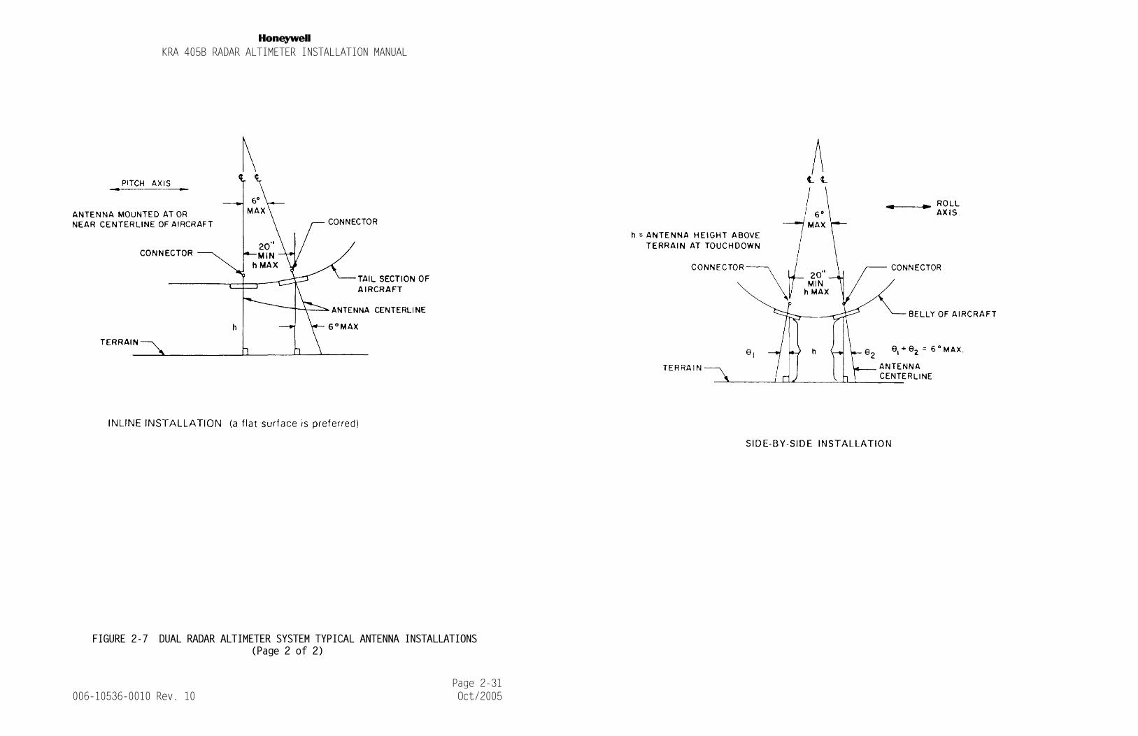
• Antennas should be pointing straight down within plus or minus 6° when the aircraft is in a level flight attitude. Antennas mounted more than 6° off the vertical will exhibit erratic op-eration on the ground. See FIGURE 2-7 DUAL RADAR ALTIMETER SYS-TEM TYPICAL ANTENNA INSTALLATIONS for examples of this type of installation.
• Antennas may be mounted in-line or side-by-side. The in-line mounting is the preferred choice of the two. When using side-by-side installations, the antennas should be mounted on a flat surface of the aircraft. The angle between the antenna center-lines should be less than 6°.
Failure to correctly position antennas will result in erratic op-eration on the ground, i.e., the needle will fluctuate as much as 20 feet, dependent upon the angle between centerlines. Air-borne operation will be satisfactory.
• Antennas should be mounted no less than 20 inches apart (measure from center to center) in order that leakage between the antennas remains at a tolerable level. The pointer may not stow above 2500 feet if the leakage between the antennas is too great.
• Antennas should not be separated by a distance greater than the antenna height above the terrain at touchdown. If the antennas are separated by more than this distance, sufficient terrain area is not illuminated for ground level operation.
• The antennas should be mounted closer than the antenna height above the terrain (but no less than 20 inches) if the angle be-tween the antennas is greater than 6° .
• Antenna locations should provide 120° clearance cones. No air-craft projection or other antenna should lie within these cones. A fixed object in the cone could cause the altimeter to lock on to a single altitude while a moving projection (gear, flaps, etc.) could cause erratic operation.
• Surface area between antennas should be free from seams or other discontinuities. NEVER mount an antenna directly on a seam. If antennas must be separated by a seam, make sure that the two piec-es of aircraft skin are electrically bonded together by adding bonding straps (i.e., have multiple straps across seam separating the two antennas).
Failure to bond properly can cause loss in system sensitivity and/or cause the pointer to momentarily come into view above 2500 feet AGL (this phenomenon is commonly called "peeking").
Page 2-11 006-10536-0010 Rev. 10 Oct/2005
NKRA 405B RADAR ALTIMETER INSTALLATION MANUAL
• Antennas must not be located in areas where excess water can ac-cumulate. Water between the antenna flange and aircraft skin will cause loss of system sensitivity and may cause peeking.
• The connectors on the KA 54 antennas should be mounted perpen-dicular to a line drawn through the receive and transmit antennas for a given unit. The antennas are designed for minimum coupling when mounted as above. Any other mounting may cause the altim-eter to lock on to erroneous altitudes when flying above 2500 feet AGL.
• The KA 54A antennas are oriented by observing the arrows pointed on the outer side of the antenna. The arrows on the transmit and receive antennas for a given unit must be on the same longitudi-nal axis. This is achieved by having the arrow head of one an-tenna pointing to the tail of the other antenna arrow (see FIGURE 2-7 DUAL RADAR ALTIMETER SYSTEM TYPICAL ANTENNA INSTALLATIONS). Alternately, the two arrows may point at each other as long as they remain on the same longitudinal axis.
If a side by side dual installation is chosen, the transmit an-tennas from the two units should be next to each other and the receive antennas should be next to each other (see FIGURE 2-7 DUAL RADAR ALTIMETER SYSTEM TYPICAL ANTENNA INSTALLATIONS).
E. IMPLEMENTING THE ANTENNA INSTALLATION
NOTE: Antenna and airframe surfaces must be free of paint or other insulating materials, including chromate. Apply Alumiprep #33 (P/N 016-01127-0000) to cleanse the metal of any residue left after removing paint or insulating material. Protect bare aluminum surfaces with Alodine 1001 (P/N 016-01128-0000) or equivalent prior to mounting antennas or bonding straps. Bonding resistance should be 2.6 milliohms or less for the best operation of the an-tenna system.
• RF/Air sealing gaskets are to be installed between KA 54A mount-ing flanges and aircraft skin.
• Minimum and maximum allowable lengths for each set of RF cables (receive and transmit) must be appropriate for proper installa-tion. System sensitivity suffers when cables lengths do not com-ply with the recommended minimum and maximum lengths. (Refer to TABLE 1-2 CABLE INSTALLATIONS).
• Make sure the cables are tight inside the cable connectors.
Page 2-12 006-10536-0010 Rev. 10 Oct/2005
NKRA 405B RADAR ALTIMETER INSTALLATION MANUAL
• Avoid the use of right angle or bulkhead coax connectors. Volt-age standing wave ratios (VSWR) are greater on these types of connectors and therefore can cause problems. If bulkhead con-nectors must be used, then connectors such as Kings Electronics Inc. P/N KA 19-102 or equivalent must be used. If right angle connectors must be used, they must be specified for operation at 4.3 GHz and extreme care should be exercised in their assembly. In either case, the tests in 2.6 POST INSTALLATION should be per-formed.
• Bends tighter than the minimum recommended bend radius can sig-nificantly increase VSWR. (See TABLE 1-2 CABLE INSTALLATIONS for minimum bend radii.)
• Excess cable lengths should be lashed securely but not to the point of cutting or distorting the cable insulation. Cutting the coax shield causes an altitude return and affects system opera-tion.
• Tighten all antenna coax connectors slightly more than finger tight.
CAUTION: DO NOT PAINT ANTENNA. OPERATION AND/OR ACCURACY MAY SUF-FER AND MAY CAUSE UNIT TO LOCK ON TO ERRONEOUS ALTITUDES.
F. ANTENNA CABLES
After the location of the antennas has been determined, a minimum length of antenna cable required for the installation may be gauged.
Measure the distance from the receiver and the transmitter connectors (located on the front of the KRA 405B) to each antenna adding enough extra length to avoid obstructions in the cable path and to allow for connection to the antenna connector.
System sensitivity suffers when cables lengths do not comply with the recommended minimum and maximum lengths.
NOTE: Refer to TABLE 1-2 CABLE INSTALLATIONS to establish min-imum and maximum cable lengths.
Page 2-13 006-10536-0010 Rev. 10 Oct/2005

NKRA 405B RADAR ALTIMETER INSTALLATION MANUAL
G. WIRING HARNESS
FIGURE 2-14 CONNECTOR PIN LOCATIONS shows the KRA 405B R/T mating connector pin connections and the KNI 415/416 mating connector pin locations. Refer to FIGURE 2-17 KRA 405B RADAR ALTIMETER SYSTEM INTERCONNECT as required.
During preparation of the wiring harness, the following precautions should be acknowledged:
• Bond and shield all parts of the aircraft electrical system such as generators and ignition systems.
• Keep the cables away from circuits carrying heavy current, pulse-transmitting equipment, 400 Hz circuits, and other sources of in-terference.
• Make all external connections of the equipment through designated connectors listed on the diagram.
• Wire size is specified on the interconnect diagram.
• Leave slack in cables to allow for free sway of the equipment.
• After installation of the cables in the aircraft and before in-stallation of the equipment, a check should be made to ensure that the aircraft power is applied only to the pins specified.
H. CONFIGURATION MODULE INSTALLATION
The KRA 405B interfaces to the CM 2000 Configuration Module.
The configuration module is an option that is only needed for installations that require the trip points to be set to a value other than the factory settings, or for installations requiring a zero feet offset. Negative values cannot be displayed by EFIS 40/50 indicators when interfaced to the radar altimeter via ARINC 429.
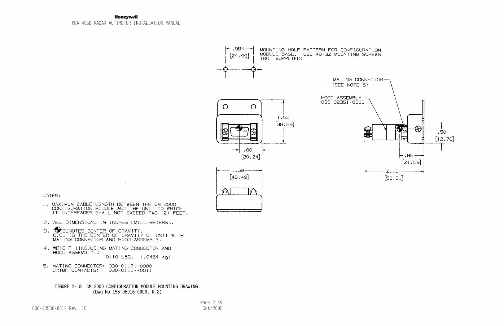
The maximum cable length between the configuration module and the KRA 405B shall not exceed two (2) feet.
NOTE: It is desirable to keep this cable length as short as pos-sible.
Refer to FIGURE 2-18 CM 2000 CONFIGURATION MODULE MOUNTING DRAWING for the CM 2000 mounting dimensions.
Page 2-14 006-10536-0010 Rev. 10 Oct/2005
NKRA 405B RADAR ALTIMETER INSTALLATION MANUAL
To program the configuration module, a KPA 900 with software 222-00366-0002 or greater is needed (See section 1.6. B. KPA 900 CONFIGURATION MODULE PROGRAMMER KIT).
Follow the instructions in the KPA 900 operator’s manual (006-05392-00XX) which is included in the KPA 900 Configuration Module Programmer Kit to perform the programming. The KRA 405B uses a configuration module type CM 2000 P/N 071-00093-0100.
2.6 POST INSTALLATION
A. POST INSTALLATION CALIBRATION
The KRA 405B DOES NOT require an AID to cause the display of zero feet while on ground. Variations in antenna cables and antenna height are resolved during a one-time calibration procedure. The result of the calibration is retained indefinitely internal to the KRA 405B.
The following conditions must be met before initiating the calibration.
1. The KRA 405B, indicator, and antennas must be installed. The KRA 405B, antennas, and coaxes must be mounted and routed in the final configuration to be representative of the normal flight conditions.
2. The calibration must be accomplished outside of the hanger with no obstacles surrounding or underneath the aircraft. Ex-traneous reflections may cause an incorrect calibration.
3. Allow a minimum of three minutes of warm-up time before ini-tiating the calibration.
4. Installations with dual radar altimeter system must calibrate each side separately. The unused side must either be unplugged or the circuit breaker disabled so as to prevent the possi-bility of interference with the side being calibrated.
The calibration is accomplished by pressing the recessed switch (SW 1) on the front of the KRA 405B (see FIGURE 2-4 KRA 405B POST INSTALLATION CALIBRATION SWITCH). Note that this switch is intentionally difficult to press. It must be pressed through a hole in the front panel with a tool no greater than 0.12 inches in diameter for at least 0.2 inches. Hold the switch for at least ten seconds to ensure that the KRA 405B accepts the switch press.
Page 2-15 006-10536-0010 Rev. 10 Oct/2005

NKRA 405B RADAR ALTIMETER INSTALLATION MANUAL
FIGURE 2-4 KRA 405B POST INSTALLATION CALIBRATION SWITCH
Verify proper on ground performance after the calibration is complete. For systems without a zero feet offset programmed into the configuration module, this will be an indication of zero feet plus or minus the system tolerance of two or three feet. For systems with a zero feet offset programmed into the configuration module, this will be an indication of the negative value of the zero feet offset plus or minus the system tolerance of two or three feet. Note that the analog indicators may not allow quantifiable negative indications.
A KRA 405B with software 01/04, 02/04, or higher contain enhancements to the calibration routine.
1. When the calibration is in process, the KRA 405B will output an altitude of 500 feet. This relieves the 10-second switch requirement. The switch may be released as soon as the indi-cator displays 500 feet. If the indicator does not display 500 feet, the switch has not been adequately pressed.
Page 2-16 006-10536-0010 Rev. 10 Oct/2005

NKRA 405B RADAR ALTIMETER INSTALLATION MANUAL
2. A calibration in an excessively noisy environment will not be accepted by the KRA 405B. A post calibration altitude of thir-ty to one hundred feet indicates a failed calibration. If this condition occurs, the calibration must be completed in a dif-ferent location.
B. GENERAL
In most cases altimeter installations that closely follow the suggestions of this manual will need no special equipment to check the integrity of the system. The steps of Paragraph 2.6. C. KRA 405B RADAR ALTIMETER POST INSTALLATION TEST PROCEDURE are sufficient to determine proper altimeter operation.
However, if more than one of the installation suggestions in this document cannot be complied with, the probability increases that a problem will exist.
In order to determine whether an altimeter installation problem does exist, the tests in Paragraphs 2.6. C. KRA 405B RADAR ALTIMETER POST INSTALLATION TEST PROCEDURE and D. TEST PROCEDURE can take the place of a flight test.
Agencies that install many altimeter systems (including other manufacturer’s equipment) will find these test procedures quite helpful. For the majority of installation problems encountered, the procedures in Paragraph 2.6. C. KRA 405B RADAR ALTIMETER POST INSTALLATION TEST PROCEDURE should prove sufficient.
Before initiating the test, check the physical condition of the units, cables, and the areas around the installations. Ensure that all cable connections are correct and that all mounts and connectors are secure.
C. KRA 405B RADAR ALTIMETER POST INSTALLATION TEST PROCEDURE
(USING MICROWAVE ABSORBER)
(1) Purpose of Test
The purpose of the following post installation test procedure is to insure that the indicator needles will stow behind the mask after the test button is pressed.
Page 2-17 006-10536-0010 Rev. 10 Oct/2005

NKRA 405B RADAR ALTIMETER INSTALLATION MANUAL
It also ensures the absence of an RF leakage path allowing the 4.3 GHz transmitter output to bleed into the system’s receiv-er, thus bypassing the normal antenna-to-ground-to-antenna path while flying above 2,500 feet AGL.
The following procedure duplicates a flight altitude greater than 2,500 feet AGL in order to find these RF leakage paths.
(2) Required Equipment
The items listed below, or their electrical equivalent, may be used to conduct the tests in this paragraph.
(3) Test Procedures
a. Turn on aircraft primary power.
b. Adjust the DH knob on the indicator to set the DH bug to 25 feet.
c. Depress the test button on the indicator. The altitude indicated should be 50 ± 5 feet and the DH lamp should be out.
d. Slowly advance the DH bug until the DH lamp lights. The bug should be set at 50 ± 5 feet at this time. Continue increasing the DH bug setting. The DH lamp should stay lit.
e. Release the test button. The indicated altitude should now be 0 ± 5 feet.
NOTE: In some installations, the tolerances given here may be greater, due to antenna location and a difference between aircraft touch down attitude and parked attitude.
QUANTITY DESCRIPTION MANUFACTURER MANU. PART NUMBER
2(1 ft sq.)
Microwave Absorber Emerson & CumminsTel: (800) 650-5740 or: (781) 961-9600
AN 75
2 TNC Female Barrels Americon 3180-0000
2 TNC Male Loads Microlab FXR TA-SMT
Page 2-18 006-10536-0010 Rev. 10 Oct/2005

NKRA 405B RADAR ALTIMETER INSTALLATION MANUAL
f. Place a one (1) foot square or larger piece of the mi-crowave absorber over each KRA 405B Antenna. The KRA 405B should unlock and the Indicator pointer should drive clockwise behind the mask.
NOTE: It may be necessary to remove the aircraft from the hanger, away from other aircraft and/or other sources of reflection in order to achieve an unlock condition (pointer be-hind mask) with the microwave absorber.
While keeping the Antennas covered with the microwave absorber, reconfirm that the self-test is operational by repeating steps b. through d. above. Release the test switch. The pointer should again go behind the mask.
g. If the indicator pointer does not stow behind the mask in Step f. above, check for a faulty RF cable or TNC connector at the R/T by exchanging the antenna coaxes cables at the R/T. Repeat Step f.
If the pointer still does not stow, disconnect the an-tenna cable from the R/T unit’s receiver port (upper connector) and terminate the receiver port with a 50 ohm load. Load the transmitter antenna into the RF absorb-er. The indicator pointer should stow behind the mask. Repeat this test for the transmitter port (lower port), and again the indicator should stow behind the mask.
Note which R/T port, when terminated, causes the indi-cator needle to stow, and continue troubleshooting in that direction.
If the R/T will not stow the indicator needle with ei-ther the Transmitter or the Receiver port terminated into a 50 ohm load, the R/T unit should be bench tested.
If the indicator pointer can be stowed with both ports terminated, reinstall the correct cables on the trans-mitter and receiver ports and remove the cables at the antenna.
Terminate these cables into the 50 ohm load one at a time while placing the microwave absorber over the other antenna.
Page 2-19 006-10536-0010 Rev. 10 Oct/2005
NKRA 405B RADAR ALTIMETER INSTALLATION MANUAL
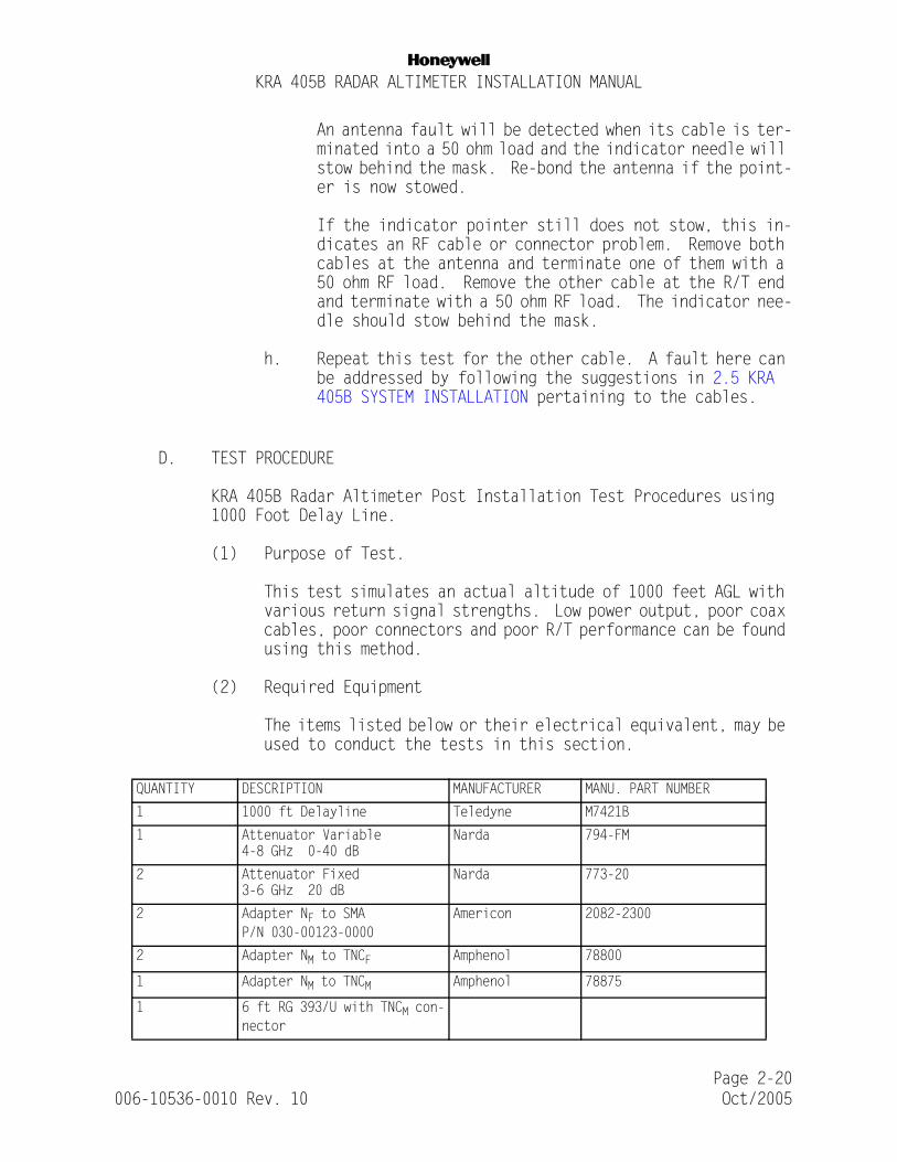
An antenna fault will be detected when its cable is ter-minated into a 50 ohm load and the indicator needle will stow behind the mask. Re-bond the antenna if the point-er is now stowed.
If the indicator pointer still does not stow, this in-dicates an RF cable or connector problem. Remove both cables at the antenna and terminate one of them with a 50 ohm RF load. Remove the other cable at the R/T end and terminate with a 50 ohm RF load. The indicator nee-dle should stow behind the mask.
h. Repeat this test for the other cable. A fault here can be addressed by following the suggestions in 2.5 KRA 405B SYSTEM INSTALLATION pertaining to the cables.
D. TEST PROCEDURE
KRA 405B Radar Altimeter Post Installation Test Procedures using 1000 Foot Delay Line.
(1) Purpose of Test.
This test simulates an actual altitude of 1000 feet AGL with various return signal strengths. Low power output, poor coax cables, poor connectors and poor R/T performance can be found using this method.
(2) Required Equipment
The items listed below or their electrical equivalent, may be used to conduct the tests in this section.
QUANTITY DESCRIPTION MANUFACTURER MANU. PART NUMBER
1 1000 ft Delayline Teledyne M7421B
1 Attenuator Variable4-8 GHz 0-40 dB
Narda 794-FM
2 Attenuator Fixed3-6 GHz 20 dB
Narda 773-20
2 Adapter NF to SMAP/N 030-00123-0000
Americon 2082-2300
2 Adapter NM to TNCF Amphenol 78800
1 Adapter NM to TNCM Amphenol 78875
1 6 ft RG 393/U with TNCM con-nector
Page 2-20 006-10536-0010 Rev. 10 Oct/2005

NKRA 405B RADAR ALTIMETER INSTALLATION MANUAL
(3) Test Procedure
a. Connect the test equipment as shown in FIGURE 2-15 KRA 405B TEST EQUIPMENT SETUP, replacing the antennas in the installation.
b. Adjust the variable attenuator to 0 dBm (this setting yields approximately 65 dBm loop loss). The KNI 415/416 should indicate 900 to 1100 feet.
c. Slowly increase the variable attenuator until the KNI 415/416 pointer goes clockwise behind the mask.
During this operation, the pointer should continue to indicate the previous altitude; 10 feet. After the pointer stows, the total attenuation in the line should be 102 dB minimum (40 dB + Attenuation in Delayline + Variable Attenuation).
d. Pointer movement while adjusting the variable attenua-tor in Step c. indicates a possible problem in the an-tenna coax.
Connect the test equipment directly to the R/T trans-mitter port and connect to the receiver port via the 6 foot test cable.
Try Step c. again. Pointer movement while adjusting the variable attenuator indicates a possible R/T problem. The R/T should be bench tested to insure proper opera-tion.
e. When Step c. attenuates a level of less than 102 dB to unlock the system, this can be an indication of possible low TX power output. Reconnect the equipment as in Step d. The pointer should stow at an attenuation of 110 dB minimum
(40 dB + Attenuation in Delayline + Variable Attenua-tion).
f. Should the unit now exhibit proper operation, check the antenna cables for total length greater than 34 feet (remember, RG 393/U attenuation per foot at 4.3 GHz is .20 dB, therefore, length greater than 34 feet may im-pair system performance).
Page 2-21 006-10536-0010 Rev. 10 Oct/2005

NKRA 405B RADAR ALTIMETER INSTALLATION MANUAL
(4) Simulated Altitude Test Procedure
The Simulated Altitude Test Procedure is to be used by the installer to test associated systems that interface with the KRA 405B. In the Simulated Altitude Test Mode, all outputs of the KRA 405B operate normally, except that they are con-trolled by a test input voltage rather than altitude. This test voltage controls all analog and digital outputs, and all three trip points.
a. Enter the Simulated Altitude Test Mode by pulling the ALTITUDE TEST EN1 and ALTITUDE TEST EN2 lines low, ≤ 3.5V. (EN1 is pin n, EN2 is pin s, and Altitude Test Input is pin m). The KRA 405B outputs will now be con-trolled by the voltage applied to the ALTITUDE TEST IN-PUT pin on the circular connector.
b. The test voltage range is from 0 to 25 volts, with 0 volts corresponding to 0 feet, and 25 volts correspond-ing to 2500 feet. Slowly run the test voltage from 0 to 25 volts, and back down to 0 volts. Confirm that the altimeter indicates a corresponding change in altitude (0 feet to 2500 feet, and back to 0 feet), and that the DH Lamp illuminates at the appropriate time.
c. Remove the low from the ALTITUDE TEST EN1 and EN2 input lines. This returns the KRA 405B to the Operational Mode. Voltages on the ALTITUDE TEST INPUT line will no longer affect the indicated altitude.
2.7 REMOVAL AND REPLACEMENT
A. KRA 405B RECEIVER/TRANSMITTER
(refer to FIGURE 2-6 KRA 405B INSTALLATION DRAWING for details)
(1) Removal
a. Detach mating coaxial cables from XMIT (P4052) and RCVR (P4053) TNC connectors on the front of the unit.
b. Detach mating cable from Cannon connector (P4051) on the front of the unit.
c. For Rack Mount, follow procedure outlined in step 1, For Shock Mount and Direct Mount, follow procedure out-lined in step 2,
Page 2-22 006-10536-0010 Rev. 10 Oct/2005

NKRA 405B RADAR ALTIMETER INSTALLATION MANUAL
1. Loosen fluted retaining screw clamp, located on the front of the mounting rack, remove triangular keeper from the front lip of the unit, and slide unit out of the rack.
2. Remove (4) #6-32 screws, securing unit to mounts, and remove.
(2) Re-installation
a. For Rack Mount, follow procedure outlined in step 1, For Shock Mount and Direct Mount, follow procedure out-lined in step 2,
1. Slide the unit into the rack. Hook the triangular keeper over the front lip of the unit and tighten the fluted retaining screw clamp located on the front of the mounting rack until secure.
2. Align unit with mounting holes and secure with (4) #6-32 screws.
b. Re-attach mating cable to Cannon connector (P4051) on the front of the unit.
c. Re-attach mating coaxial cables to XMIT (P4052) and RCVR (P4053) TNC connectors on the front of the unit.
B. KNI 415/416 INDICATOR
(refer to FIGURE 2-5 KNI 415/416 INSTALLATION DRAWING for details)
(1) Removal
a. Detach mating cable from Cannon connector (P4151/P4161) on the back of the unit.
b. Remove (4) #6-32 screws, securing unit to panel. Unit may be front or rear mounted relative to panel.
(2) Re-installation
a. Align unit with panel mounting holes and secure with (4) #6-32 screws. Unit may be front or rear mounted rela-tive to panel.
Page 2-23 006-10536-0010 Rev. 10 Oct/2005

NKRA 405B RADAR ALTIMETER INSTALLATION MANUAL
b. Re-attach mating cable to Cannon connector (P4151/P4161) on the back of the unit.
C. ANTENNAS
(Refer to FIGURE 2-8 KA 54 ANTENNA OUTLINE AND MOUNTING DRAWING through FIGURE 2-12 HONEYWELL GT 7003586 (SENSOR SYSTEMS TYPE S67-2002-4 ANTENNA))
Refer to section 2.5. E. IMPLEMENTING THE ANTENNA INSTALLATION for additional information and suggestions relating to installation of antennas.
(1) Removal
a. Detach mating coaxial cable from antenna TNC connector.
b. Remove the fasteners attaching the antenna to the air-frame. (The number and pattern will vary depending on antenna type, consult proper antenna mounting drawing for details).
(2) Re-installation
a. Align antenna with panel mounting holes and secure with fasteners. (The number and pattern will vary depending on antenna type, consult proper antenna mounting draw-ing for details).
b. Re-attach mating coaxial cable to antenna TNC connec-tor.
2.8 HONEYWELL MAINTENANCE RECOMMENDATIONS
The KRA 405B Radar Altimeter System has been designed for “on-condition” maintenance. For details relating to “on condition” maintenance, refer to Honeywell Service Memo SM #292, P/N 600-08292-XXXX.
Page 2-24 006-10536-0010 Rev. 10 Oct/2005

NKRA 405B RADAR ALTIMETER INSTALLATION MANUAL
Page 2-25006-10536-0010 Rev. 10 Oct/2005
FIGURE 2-5 KNI 415/416 INSTALLATION DRAWING (Dwg No 155-05160-0000, R-1)

NKRA 405B RADAR ALTIMETER INSTALLATION MANUAL
Page 2-27006-10536-0010 Rev. 10 Oct/2005
FIGURE 2-6 KRA 405B INSTALLATION DRAWING (Dwg No 155-06030-0000 R-0)

NKRA 405B RADAR ALTIMETER INSTALLATION MANUAL
Page 2-29006-10536-0010 Rev. 10 Oct/2005
FIGURE 2-7 DUAL RADAR ALTIMETER SYSTEM TYPICAL ANTENNA INSTALLATIONS (Page 1 of 2)
NKRA 405B RADAR ALTIMETER INSTALLATION MANUAL
Page 2-31006-10536-0010 Rev. 10 Oct/2005
FIGURE 2-7 DUAL RADAR ALTIMETER SYSTEM TYPICAL ANTENNA INSTALLATIONS (Page 2 of 2)
NKRA 405B RADAR ALTIMETER INSTALLATION MANUAL
Page 2-33006-10536-0010 Rev. 10 Oct/2005
FIGURE 2-8 KA 54 ANTENNA OUTLINE AND MOUNTING DRAWING DORNE MARGOLIN INC. TYPE DMPN 3-3/A, (Dwg No 155-05159-0000, R-1)

NKRA 405B RADAR ALTIMETER INSTALLATION MANUAL
Page 2-35006-10536-0010 Rev. 10 Oct/2005
FIGURE 2-9 UBC TYPE AD 43013-1 AND COMANT TYPE 01-34-04531 ANTENNA OUTLINE AND MOUNTING DRAWING, (Dwg No 155-05166-0000, R-0)

NKRA 405B RADAR ALTIMETER INSTALLATION MANUAL
Page 2-37006-10536-0010 Rev. 10 Oct/2005
FIGURE 2-10 DORNE MARGOLIN TYPE DMPN 3-4/A ANTENNA OUTLINE AND MOUNTING DIAGRAM, (Dwg No 155-05167-0000, R-2)
NKRA 405B RADAR ALTIMETER INSTALLATION MANUAL
Page 2-39006-10536-0010 Rev. 10 Oct/2005
FIGURE 2-11 KA 54A ANTENNA (SENSOR SYSTEMS TYPE S67-2002 & DORNE AND MARGOLIN TYPE DMPN 19-2-1)
OUTLINE AND MOUNTING DRAWING, (P/N 071-01501-0000, R-AE)

NKRA 405B RADAR ALTIMETER INSTALLATION MANUAL
Page 2-41006-10536-0010 Rev. 10 Oct/2005
FIGURE 2-12 HONEYWELL GT 7003586 (SENSOR SYSTEMS TYPE S67-2002-4 ANTENNA) OUTLINE AND MOUNTING DRAWING

NKRA 405B RADAR ALTIMETER INSTALLATION MANUAL
NOTE: Proper operation of a Radar Altimeter System depends upon the VSWR of the antenna cable. Therefore, extreme care must be ex-ercised in assembling the TNC connector to the RG 393/U cable. Strict adherence to the above instructions will ensure a good VSWR of the antenna cables.
FIGURE 2-13 TNC COAX/CONNECTOR ASSEMBLY (RG 393/U) (P/N 030-00108-0004)
Page 2-43 006-10536-0010 Rev. 10 Oct/2005

NKRA 405B RADAR ALTIMETER INSTALLATION MANUAL
KRA 405B MATING CONNECTOR (P4051)P/N 030-02077-0000
KRA 415/416 MATING CONNECTOR (P4151/P4161)P/N 030-02210-0001
FIGURE 2-14 CONNECTOR PIN LOCATIONS
Page 2-44 006-10536-0010 Rev. 10 Oct/2005

NKRA 405B RADAR ALTIMETER INSTALLATION MANUAL
FIGURE 2-15 KRA 405B TEST EQUIPMENT SETUP
Page 2-45 006-10536-0010 Rev. 10 Oct/2005

NKRA 405B RADAR ALTIMETER INSTALLATION MANUAL
FIGURE 2-16 EXTERNAL SONALERT (W/15 SECOND DH AUDIO FADER)
Page 2-46 006-10536-0010 Rev. 10 Oct/2005

NKRA 405B RADAR ALTIMETER INSTALLATION MANUAL
Page 2-47006-10536-0010 Rev. 10 Oct/2005
FIGURE 2-17 KRA 405B RADAR ALTIMETER SYSTEM INTERCONNECT (Dwg No 155-01645-0000, R-AD)
NKRA 405B RADAR ALTIMETER INSTALLATION MANUAL
Page 2-49006-10536-0010 Rev. 10 Oct/2005
FIGURE 2-18 CM 2000 CONFIGURATION MODULE MOUNTING DRAWING (Dwg No 155-06016-0000, R-2)

NKRA 405B RADAR ALTIMETER INSTALLATION MANUAL
SECTION IIIOPERATION
3.1 GENERAL
The KNI 415 and KNI 416 Radar Altimeter Indicators are shown in FIGURE 3-1 KNI 415 CONTROL FUNCTIONS and FIGURE 3-2 KNI 416 CONTROL FUNCTIONS and are discussed below.
• Altitude Scale:
The KNI 415 scale gives accurate altitude indications from -20 to +2000 feet. From -20 to 500 feet each mark on the scale represents 10 feet. From 500 to 2000 feet, each mark represents 100 feet.
The KNI 416 scale gives accurate altitude indications from -10 to +2000 feet. From -10 to 200 feet each mark represents 5 feet, from 200 to 500 feet each mark represents 20 feet, and from 500 to 2000 feet each mark represents 100 feet.
• Indicator Needle:
The AGL altitude in feet is displayed beneath this needle. Needle will be clockwise behind mask when above 2000 feet.
• Flag:
Indicates invalid altitude information is being displayed or self test button is depressed.
• Self Test Button:
This button is used to test the Radar Altimeter R/T and indicator. When the button is depressed, the flag will come into view and 50 ± 5 feet will be displayed.
• DH Knob:
This knob controls the DH (Decision Height) bug. By turning it clock-wise, the DH bug will increase in altitude; counterclockwise, the bug will decrease in altitude.
• DH Bug:
Indicates altitude during an approach at which the DH lamp will light.
Page 3-1 006-10536-0010 Rev. 10 Oct/2005
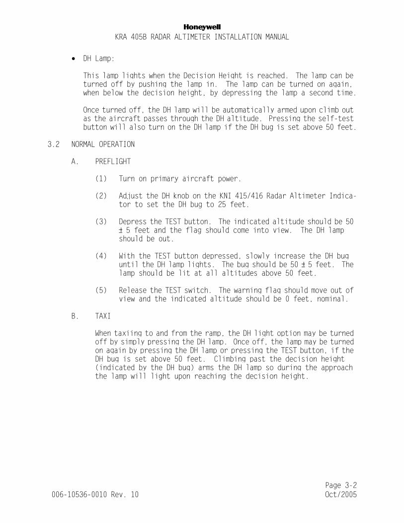
NKRA 405B RADAR ALTIMETER INSTALLATION MANUAL
• DH Lamp:
This lamp lights when the Decision Height is reached. The lamp can be turned off by pushing the lamp in. The lamp can be turned on again, when below the decision height, by depressing the lamp a second time.
Once turned off, the DH lamp will be automatically armed upon climb out as the aircraft passes through the DH altitude. Pressing the self-test button will also turn on the DH lamp if the DH bug is set above 50 feet.
3.2 NORMAL OPERATION
A. PREFLIGHT
(1) Turn on primary aircraft power.
(2) Adjust the DH knob on the KNI 415/416 Radar Altimeter Indica-tor to set the DH bug to 25 feet.
(3) Depress the TEST button. The indicated altitude should be 50 ± 5 feet and the flag should come into view. The DH lamp should be out.
(4) With the TEST button depressed, slowly increase the DH bug until the DH lamp lights. The bug should be 50 ± 5 feet. The lamp should be lit at all altitudes above 50 feet.
(5) Release the TEST switch. The warning flag should move out of view and the indicated altitude should be 0 feet, nominal.
B. TAXI
When taxiing to and from the ramp, the DH light option may be turned off by simply pressing the DH lamp. Once off, the lamp may be turned on again by pressing the DH lamp or pressing the TEST button, if the DH bug is set above 50 feet. Climbing past the decision height (indicated by the DH bug) arms the DH lamp so during the approach the lamp will light upon reaching the decision height.
Page 3-2 006-10536-0010 Rev. 10 Oct/2005

NKRA 405B RADAR ALTIMETER INSTALLATION MANUAL
C. IN FLIGHT OPERATION
At normal cruise altitudes above 2000 feet, the indicator pointer is behind the mask and the warning flag is hidden from view above 2,500 feet. A Flight Control System (FCS) warn is a failure warning signal to systems requiring accurate above ground level (AGL) altitude information. The FCS warn presents a red flag during operation above 2000 feet, during self test, loss of power, and loss of signal strength to alert the pilot to possible failures.
D. APPROACH
During the actual approach, the Radar Altimeter System provides altitude and altitude trip information to the Flight Control System. When the approach plans are reviewed prior to beginning the actual approach, the pilot should set the DH bug to the decision height altitude, and check altimeter operation. When decision height is reached, the DH Lamp lights to alert the pilot that a decision should be made. The DH Lamp may then be turned off by pressing the lamp in.
E. PUSH-TO-TEST MODE
(1) To check altimeter operation, depress the TEST button. The following should be noted on the altimeter:
a. 50 ± 5 feet should be indicated.
b. The flag should come into view.
c. The DH lamp should light (if the DH setting is above 50 feet).
d. Verify that the pointer comes on scale at 2000 feet AGL by using the baro corrected barometric altitude as a reference. (This reference is for self test only and should not be used as an absolute altitude).
(2) If altimeter does not operate as specified above, refer to Self-Test Diagnostics, paragraph 3.3 SELF-TEST DIAGNOSTICS .
Page 3-3 006-10536-0010 Rev. 10 Oct/2005
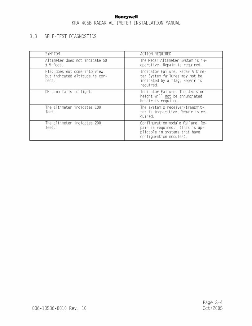
NKRA 405B RADAR ALTIMETER INSTALLATION MANUAL
3.3 SELF-TEST DIAGNOSTICS
SYMPTOM ACTION REQUIRED
Altimeter does not indicate 50 ± 5 feet.
The Radar Altimeter System is in-operative. Repair is required.
Flag does not come into view, but indicated altitude is cor-rect.
Indicator Failure. Radar Altime-ter System failures may not be indicated by a flag. Repair is required.
DH Lamp fails to light. Indicator Failure. The decision height will not be annunciated. Repair is required.
The altimeter indicates 100 feet.
The system’s receiver/transmit-ter is inoperative. Repair is re-quired.
The altimeter indicates 200 feet.
Configuration module failure. Re-pair is required. (This is ap-plicable in systems that have configuration modules).
Page 3-4 006-10536-0010 Rev. 10 Oct/2005

NKRA 405B RADAR ALTIMETER INSTALLATION MANUAL
FIGURE 3-1 KNI 415 CONTROL FUNCTIONS
Page 3-5 006-10536-0010 Rev. 10 Oct/2005

NKRA 405B RADAR ALTIMETER INSTALLATION MANUAL
FIGURE 3-2 KNI 416 CONTROL FUNCTIONS
Page 3-6 006-10536-0010 Rev. 10 Oct/2005

NKRA 405B RADAR ALTIMETER INSTALLATION MANUAL
TSO APPENDIX
ENVIRONMENTAL QUALIFICATION FORMS
Page AppE-1 006-10536-0010 Rev. 10 Oct/2005

NKRA 405B RADAR ALTIMETER INSTALLATION MANUAL
THIS PAGE IS RESERVED
Page AppE-2 006-10536-0010 Rev. 10 Oct/2005

NKRA 405B RADAR ALTIMETER INSTALLATION MANUAL
Page AppE-3 006-10536-0010 Rev. 10 Oct/2005

NKRA 405B RADAR ALTIMETER INSTALLATION MANUAL
Page AppE-4 006-10536-0010 Rev. 10 Oct/2005

NKRA 405B RADAR ALTIMETER INSTALLATION MANUAL
Page AppE-5 006-10536-0010 Rev. 10 Oct/2005

NKRA 405B RADAR ALTIMETER INSTALLATION MANUAL
THIS PAGE IS RESERVED
Page AppE-6 006-10536-0010 Rev. 10 Oct/2005


