Embed Size (px)
Citation preview

INSTALLATION MANUAL
CNH 7,8,9 SERIES COMBINES
5000 Series Track Modules

Installation Manual
CNH 7, 8, 9 Series Combine
Table of Contents
1 Definitions&Abbreviations: 1-1
2 RecommendedToolList 1-1
3 PartsList 3-1
4 LiftingInstructions 4-1
5 InstallationofOscillationStops 5-1
6 DeterminingtheLeft-handandRight-handTrackModule 6-1
7 TrackModuleInstallation 7-1
8 Break-inandBeltCare/Conditioning 8-1
9 Specifications 9-1
10 IndexofFigures,Sketches,andTables 10-1

Installation Manual
CNH 7, 8, 9 Series Combine 1-1
1 Definitions & Abbreviations:HHCS - Hex Head Cap ScrewSHCS - Socket Head Cap Screw
RH Right Hand Module or Right Hand Side of the Combine
LH Left Hand Module or Left Hand Side of the Combine
HIM High Idler Module
- Indicates possible hazardous situation that, if not avoided, may cause minor or moderate personal injury. This may also be used to indicate possible equipment damage, if not avoided.- Indicates possible hazardous situation that, if not avoided, may cause death or serious personal injury.
- Indicates a prohibitive situation, DO NOT PERFORM
2 Recommended Tool List2.1 StandardToolList
• 34 mm Socket ¾” Drive
• 30 mm Socket ¾” Drive
• 19 mm Socket ½” Drive
• 30 mm Combination Wrench
• 15” Extension ¾” Drive
• ½” Drive Impact Wrench
• ½” to ¾” Drive Adapter
• ¾” Drive Ratchet
• ½” Drive Ratchet
• 600 lb. Torque Wrench
• Paint Marker
• 4” Disc Grinder - Electric
• 4” Wire Brush Cup
• Lacquer Thinner
2.2 MaterialHandlingEquipment• 8000 lb. Capacity Fork truck
• Air Jack and Jack Stands
Installation Manual
CNH 7, 8, 9 Series Combine3-1
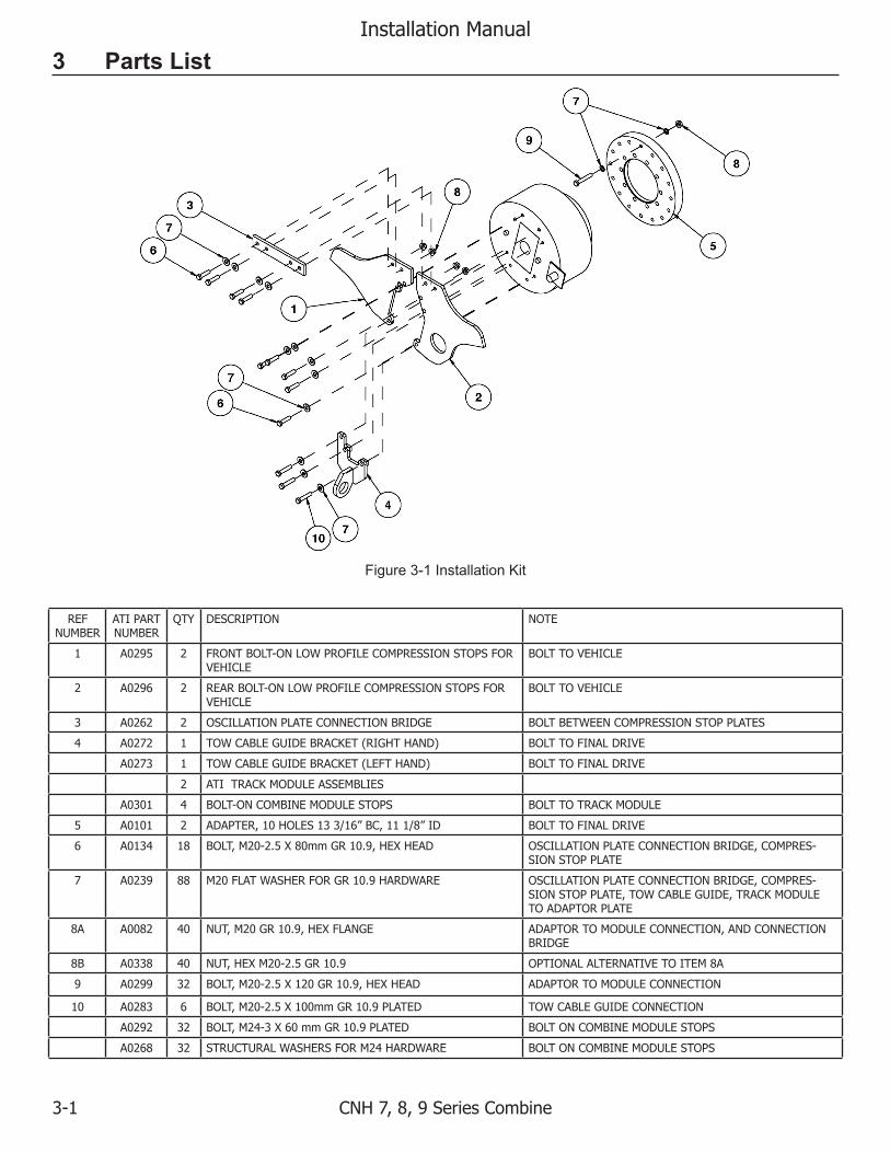
3 Parts List
REFNUMBER
ATIPARTNUMBER
QTY DESCRIPTION NOTE
1 A0295 2 FRONTBOLT-ONLOWPROFILECOMPRESSIONSTOPSFORVEHICLE
BOLTTOVEHICLE
2 A0296 2 REARBOLT-ONLOWPROFILECOMPRESSIONSTOPSFORVEHICLE
BOLTTOVEHICLE
3 A0262 2 OSCILLATIONPLATECONNECTIONBRIDGE BOLTBETWEENCOMPRESSIONSTOPPLATES
4 A0272 1 TOWCABLEGUIDEBRACKET(RIGHTHAND) BOLTTOFINALDRIVE
A0273 1 TOWCABLEGUIDEBRACKET(LEFTHAND) BOLTTOFINALDRIVE
2 ATITRACKMODULEASSEMBLIES
A0301 4 BOLT-ONCOMBINEMODULESTOPS BOLTTOTRACKMODULE
5 A0101 2 ADAPTER,10HOLES133/16”BC,111/8”ID BOLTTOFINALDRIVE
6 A0134 18 BOLT,M20-2.5X80mmGR10.9,HEXHEAD OSCILLATIONPLATECONNECTIONBRIDGE,COMPRES-SIONSTOPPLATE
7 A0239 88 M20FLATWASHERFORGR10.9HARDWARE OSCILLATIONPLATECONNECTIONBRIDGE,COMPRES-SIONSTOPPLATE,TOWCABLEGUIDE,TRACKMODULETOADAPTORPLATE
8A A0082 40 NUT,M20GR10.9,HEXFLANGE ADAPTORTOMODULECONNECTION,ANDCONNECTIONBRIDGE
8B A0338 40 NUT,HEXM20-2.5GR10.9 OPTIONALALTERNATIVETOITEM8A
9 A0299 32 BOLT,M20-2.5X120GR10.9,HEXHEAD ADAPTORTOMODULECONNECTION
10 A0283 6 BOLT,M20-2.5X100mmGR10.9PLATED TOWCABLEGUIDECONNECTION
A0292 32 BOLT,M24-3X60mmGR10.9PLATED BOLTONCOMBINEMODULESTOPS
A0268 32 STRUCTURALWASHERSFORM24HARDWARE BOLTONCOMBINEMODULESTOPS
Figure 3-1 Installation Kit
Installation Manual
CNH 7, 8, 9 Series Combine 4-1
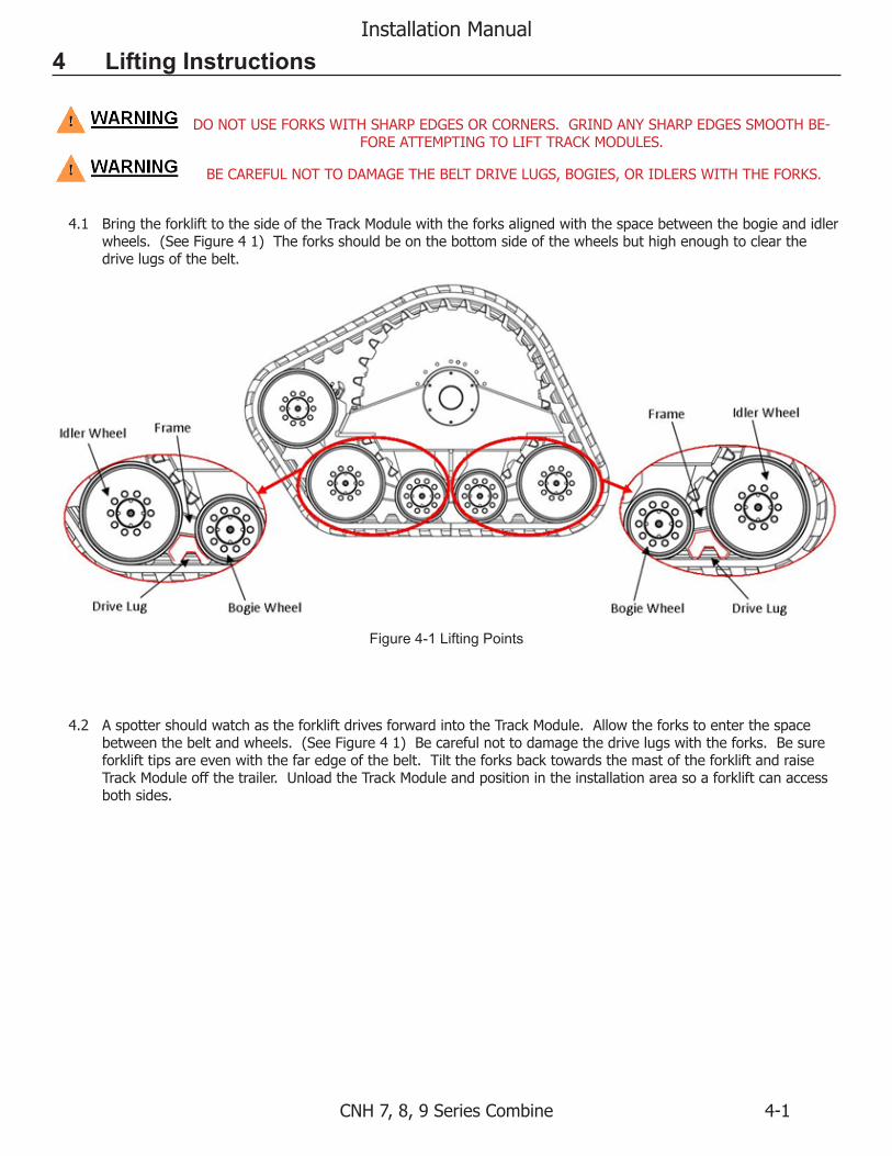
4 Lifting Instructions
DONOTUSEFORKSWITHSHARPEDGESORCORNERS.GRINDANYSHARPEDGESSMOOTHBE-FOREATTEMPTINGTOLIFTTRACKMODULES.
BECAREFULNOTTODAMAGETHEBELTDRIVELUGS,BOGIES,ORIDLERSWITHTHEFORKS.
4.1 BringtheforklifttothesideoftheTrackModulewiththeforksalignedwiththespacebetweenthebogieandidlerwheels.(SeeFigure41)Theforksshouldbeonthebottomsideofthewheelsbuthighenoughtoclearthedrivelugsofthebelt.
4.2 AspottershouldwatchastheforkliftdrivesforwardintotheTrackModule.Allowtheforkstoenterthespacebetweenthebeltandwheels.(SeeFigure41)Becarefulnottodamagethedrivelugswiththeforks.Besureforklifttipsareevenwiththefaredgeofthebelt.TilttheforksbacktowardsthemastoftheforkliftandraiseTrackModuleoffthetrailer.UnloadtheTrackModuleandpositionintheinstallationareasoaforkliftcanaccessbothsides.
Figure 4-1 Lifting Points

Installation Manual
CNH 7, 8, 9 Series Combine5-1
5 Installation of Oscillation Stops5.1 Raiseandsupportvehiclepermanufacturer’s
instruction.
5.2 Removewheelassembly.
5.3 Disconnectandremovefinaldriveinputshaft.
5.4 Removethefrontupperthreeboltsattachingthefinaldrivetotheaxleextension.
5.5 InstallthefrontoscillationstopplatewithnewboltsasshowninFigure5-2.Onlyinstallthetoptwoboltsatthistime.Torquetheboltstothevehiclemanufacturer’sspecification.
5.6 Removetherearupperthreeboltsattachingthefinaldrivetotheaxleextension.
Figure 5-1 Front Bolt Removal
Figure 5-2 Front Oscillation Stop Installation
Figure 5-3 Rear Bolt Removal
Installation Manual
CNH 7, 8, 9 Series Combine 5-2
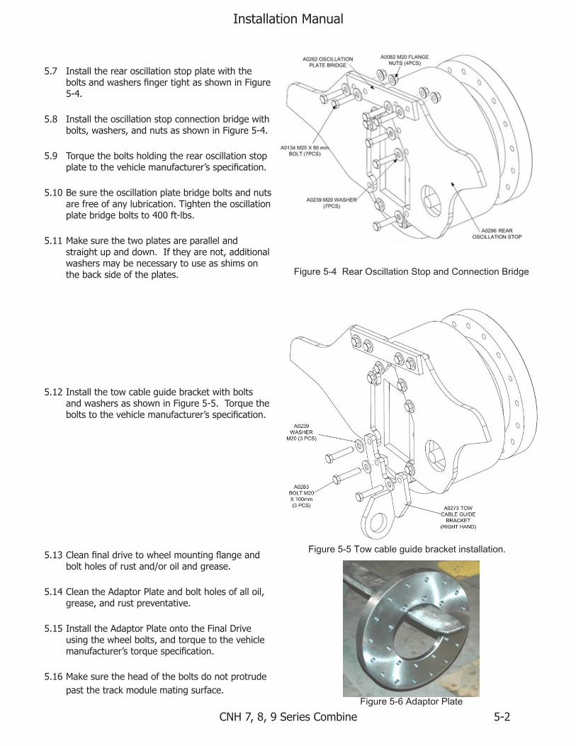
5.7 InstalltherearoscillationstopplatewiththeboltsandwashersfingertightasshowninFigure5-4.
5.8 Installtheoscillationstopconnectionbridgewithbolts,washers,andnutsasshowninFigure5-4.
5.9 Torquetheboltsholdingtherearoscillationstopplatetothevehiclemanufacturer’sspecification.
5.10 Besuretheoscillationplatebridgeboltsandnutsarefreeofanylubrication.Tightentheoscillationplatebridgeboltsto400ft-lbs.
5.11 Makesurethetwoplatesareparallelandstraightupanddown.Iftheyarenot,additionalwashersmaybenecessarytouseasshimsonthebacksideoftheplates.
5.12 InstallthetowcableguidebracketwithboltsandwashersasshowninFigure5-5.Torquetheboltstothevehiclemanufacturer’sspecification.
5.13 Cleanfinaldrivetowheelmountingflangeandboltholesofrustand/oroilandgrease.
5.14 CleantheAdaptorPlateandboltholesofalloil,grease,andrustpreventative.
5.15 InstalltheAdaptorPlateontotheFinalDriveusingthewheelbolts,andtorquetothevehiclemanufacturer’storquespecification.
5.16 Makesuretheheadoftheboltsdonotprotrudepastthetrackmodulematingsurface.
Figure 5-4 Rear Oscillation Stop and Connection Bridge
Figure 5-5 Tow cable guide bracket installation.
Figure 5-6 Adaptor Plate
Installation Manual
CNH 7, 8, 9 Series Combine6-1
6 Determining the Left-hand and Right-hand Track Module
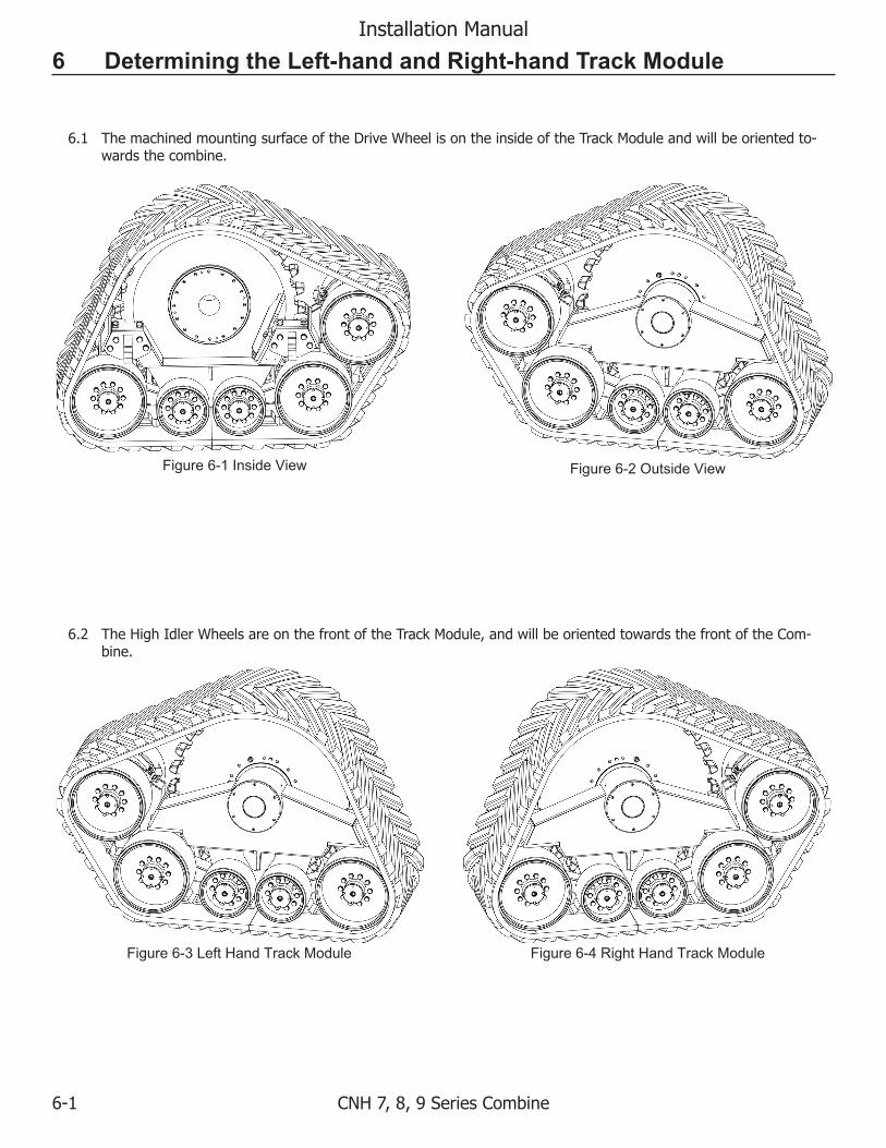
6.1 ThemachinedmountingsurfaceoftheDriveWheelisontheinsideoftheTrackModuleandwillbeorientedto-wardsthecombine.
6.2 TheHighIdlerWheelsareonthefrontoftheTrackModule,andwillbeorientedtowardsthefrontoftheCom-bine.
Figure 6-1 Inside View Figure 6-2 Outside View
Figure 6-3 Left Hand Track Module Figure 6-4 Right Hand Track Module

Installation Manual
CNH 7, 8, 9 Series Combine 7-1
7 Track Module Installation7.1 Removeallsurfacepreservativefromthecontact
surfaceofDriveSpindletoAdapterPlateandallboltholes.Useisopropylalcohol,acetoneorlacquerthinner.
YOUCANBESERIOUSLYINJUREDIFYOUAREEX-POSEDORCOMEINCONTACTWITHTHESECHEMI-
CALS.WEARPROTECTIVECLOTHING.
7.2 BringtheforklifttotheoutsideoftheTrackModulewiththeforksalignedwiththespacebetweenthebogieandidlerwheels.Theforksshouldbeonthebottomsideofthewheelsbuthighenoughtoclearthedrivelugsofthebelt.
BECAREFULNOTTODAMAGETHEBELTDRIVELUGS,BOGIES,ORIDLERSWITHTHEFORKS.
7.3 AspottershouldwatchastheforkliftdrivesforwardintotheTrackModule.Allowtheforkstoenterthespacebetweenthebeltandwheels.Becarefulnottodamagethedrivelugswiththeforks.
7.4 RaisetheTrackModuleoffthefloorandalignwiththeAdaptorPlate.TheTrackModuleshouldbeslightlytiltedback,awayfromthecombine.
7.5 AlignthemountingholesontheDriveWheelwiththeholesintheAdaptorPlatebyrotatingtheAdaptorPlate.Note:thefinaldriveinputshaftmustberemoved.
7.6 SlowlybringtheTrackModuleintocontactwiththeAdapterPlate.
DONOTGETBETWEENTHE TRACKMODULEANDTHECOMBINE!
KEEPHANDSANDFEETCLEARWHENALIGNINGTRACKMODULETOCOMBINE!
Figure 7-1 Clean Mounting Surface
Figure 7-2 Track Module Lifting Points
Figure 7-3 Track Module Installation
Installation Manual
CNH 7, 8, 9 Series Combine7-2
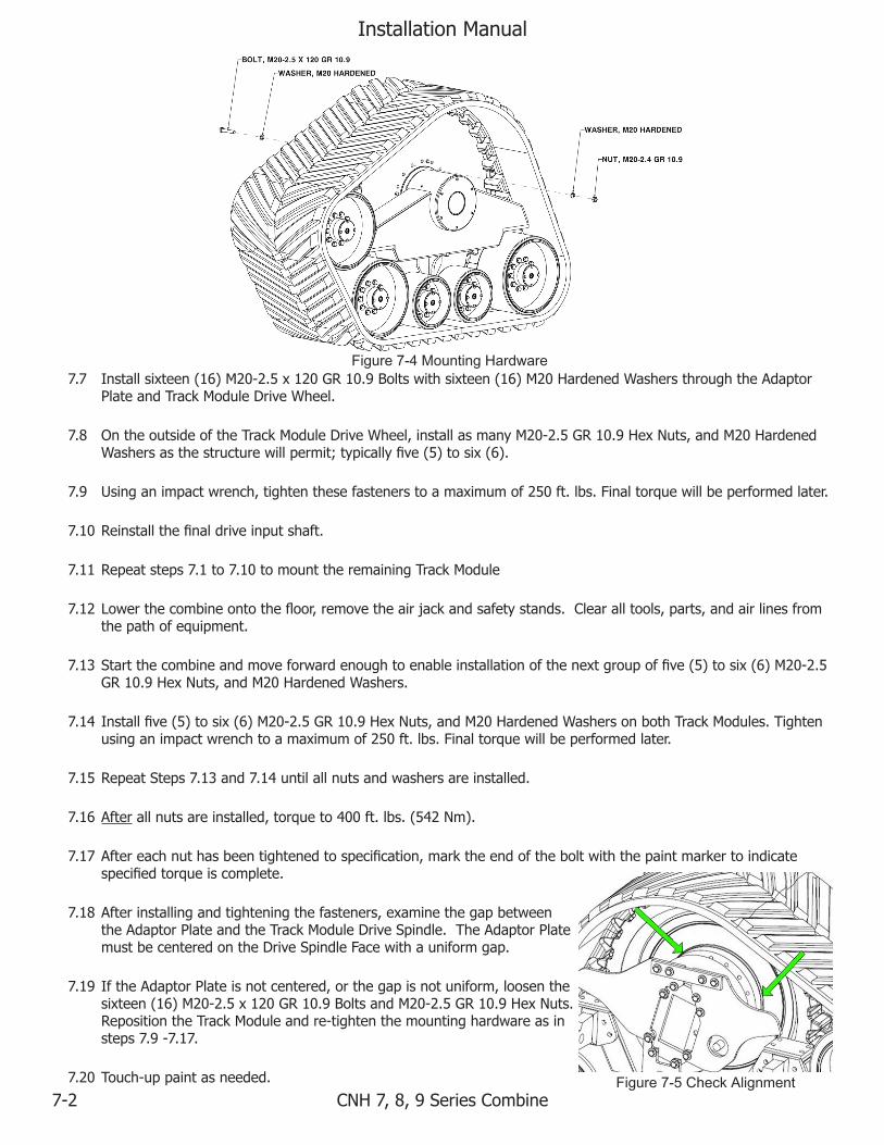
7.7 Installsixteen(16)M20-2.5x120GR10.9Boltswithsixteen(16)M20HardenedWashersthroughtheAdaptorPlateandTrackModuleDriveWheel.
7.8 OntheoutsideoftheTrackModuleDriveWheel,installasmanyM20-2.5GR10.9HexNuts,andM20HardenedWashersasthestructurewillpermit;typicallyfive(5)tosix(6).
7.9 Usinganimpactwrench,tightenthesefastenerstoamaximumof250ft.lbs.Finaltorquewillbeperformedlater.
7.10 Reinstallthefinaldriveinputshaft.
7.11 Repeatsteps7.1to7.10tomounttheremainingTrackModule
7.12 Lowerthecombineontothefloor,removetheairjackandsafetystands.Clearalltools,parts,andairlinesfromthepathofequipment.
7.13 Startthecombineandmoveforwardenoughtoenableinstallationofthenextgroupoffive(5)tosix(6)M20-2.5GR10.9HexNuts,andM20HardenedWashers.
7.14 Installfive(5)tosix(6)M20-2.5GR10.9HexNuts,andM20HardenedWashersonbothTrackModules.Tightenusinganimpactwrenchtoamaximumof250ft.lbs.Finaltorquewillbeperformedlater.
7.15 RepeatSteps7.13and7.14untilallnutsandwashersareinstalled.
7.16 Afterallnutsareinstalled,torqueto400ft.lbs.(542Nm).
7.17 Aftereachnuthasbeentightenedtospecification,marktheendoftheboltwiththepaintmarkertoindicatespecifiedtorqueiscomplete.
7.18 Afterinstallingandtighteningthefasteners,examinethegapbetweentheAdaptorPlateandtheTrackModuleDriveSpindle.TheAdaptorPlatemustbecenteredontheDriveSpindleFacewithauniformgap.
7.19 IftheAdaptorPlateisnotcentered,orthegapisnotuniform,loosenthesixteen(16)M20-2.5x120GR10.9BoltsandM20-2.5GR10.9HexNuts.RepositiontheTrackModuleandre-tightenthemountinghardwareasinsteps7.9-7.17.
7.20 Touch-uppaintasneeded.
Figure 7-4 Mounting Hardware
Figure 7-5 Check Alignment

Installation Manual
CNH 7, 8, 9 Series Combine 8-1
8 Break-in and Belt Care/Conditioning
Break-in Procedure
8.1 Thefollowingisthebreak-inprocedureforthemodulartracksystemafterinstallationofanewtracksystemonavehicle,orinstallationofanewbeltonanexistingtrackmodule.Priortooperating/runningtheequipment,talcmustbeappliedtothedrivelugsoftherubbertrackbelttoaidintheproperbeltconditioning.
8.2 Thetalcshouldbepouredintotheinsideofthedrivewheelfromtheinsideofthetrackmodule.
8.3 Pouronecupoftalcintothefrontofthedrivewheelandonecupintotherearofthedrivewheel.
8.4 Movingtheequipmentforward(orreverse)willspreadthetalcoverthedrivelugteeth.
8.5 Besurealltheguide/drivelugshavetalconallsurfaces.
8.6 Alwaysexposeneworcleantracktodryanddustysoilconditionsassoonaspossible.
8.7 Runvehicleforten(10)hoursafterinstallation.Then,checkthehydraulicpressureonthebelttensionsystemandthetorqueonallwheelboltsandTrackModulemountingbolts.
8.8 Repeatcheckingthepressuresandtorquevaluesuntilstabilized.
VEHICLEMUSTBESTATIONARYANDENGINEOFFBEFOREPOURINGTALCINTOTRACKMODULES!
Roading
8.9 Highspeedroadingincreasestreadwearratesupto15timesthefieldwearratesandbuildsexcessiveheatwhichcanreducedrivelugandtractionluglife.Roadingshouldbeavoidedpriortothecompletionofthebreak-inphase,particularlyonasphaltroads.Ifroadtravelisnecessarywithnewtracks,thenreducespeedanduseadrylubricantsuchastalc.
8.10 Extendedroadingofanewtrackduringthebreak-inperiodandespeciallypriortotheinitialfielduseisnotrec-ommended,andmayleadtosignificantdrivelugandtractionlugscuffingduetoheat.Break-inwearisnon-war-rantable.
Figure 8-1 Apply Talc Figure 8-2 Cover Drive Lugs with Talc
Installation Manual
CNH 7, 8, 9 Series Combine9-1
9 Specifications
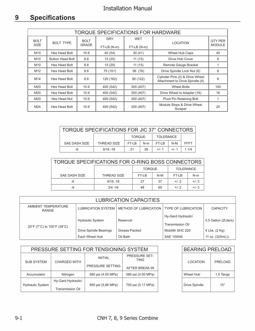
TORQUE SPECIFICATIONS FOR HARDWAREBOLT SIZE BOLT TYPE BOLT
GRADE
DRY
FT-LB (N-m)
WET
FT-LB (N-m)LOCATION QTY PER
MODULE
M10 Hex Head Bolt 10.9 40 (54) 30 (41) Wheel Hub Caps 40
M10 Button Head Bolt 8.8 15 (20) 11 (15) Drive Hub Cover 6
M10 Hex Head Bolt 8.8 15 (20) 11 (15) Remote Gauge Bracket 1
M12 Hex Head Bolt 8.8 75 (101) 56 (76) Drive Spindle Lock Nut (6) 6
M14 Hex Head Bolt 8.8 120 (162) 90 (122) Cylinder Pins (2) & Drive Wheel Attachment to Drive Spindle (4) 6
M20 Hex Head Bolt 10.9 400 (542) 300 (407) Wheel Bolts 100
M20 Hex Head Bolt 10.9 400 (542) 300 (407) Drive Wheel to Adapter (16) 16
M20 Hex Head Nut 10.9 400 (542) 300 (407) Pivot Pin Retaining Bolt 1
M24 Hex Head Bolt 10.9 400 (542) 300 (407) Module Stops & Drive Wheel Scraper 20
TORQUE SPECIFICATIONS FOR JIC 37° CONNECTORSTORQUE TOLERANCE
SAE DASH SIZE THREAD SIZE FT-LB N-m FT-LB N-M FFFT
-6 9/16 -18 21 28 +/- 1 +/- 1 1 1/4
TORQUE SPECIFICATIONS FOR O-RING BOSS CONNECTORSTORQUE TOLERANCE
SAE DASH SIZE THREAD SIZE FT-LB N-M FT-LB N-m
-6 9/16 -18 27 37 +/- 2 +/- 3
-8 3/4 -16 48 65 +/- 2 +/- 3
LUBRICATION CAPACITIESAMBIENT TEMPERATURE
RANGE LUBRICATION SYSTEM METHOD OF LUBRICATION TYPE OF LUBRICATION CAPACITY
20°F (7°C) to 100°F (38°C)
Hydraulic System ReservoirHy-Gard Hydraulic/
Transmission Oil0.5 Gallon (2Liters)
Drive Spindle Bearings Grease Packed Mobilith SHC 220 4 Lbs. (2 Kg)
Each Wheel Hub Oil Bath SAE 15W40 11 oz. (325mL))
PRESSURE SETTING FOR TENSIONING SYSTEM BEARING PRELOAD
SUB SYSTEM CHARGED WITHINITIAL
PRESSURE SETTING
PRESSURE SET-TING
AFTER BREAK-IN
LOCATION PRELOAD
Accumulator Nitrogen 580 psi (4.00 MPa) 580 psi (4.00 MPa) Wheel Hub 1.5 Tangs
Hydraulic SystemHy-Gard Hydraulic/
Transmission Oil850 psi (5.86 MPa) 750 psi (5.17 MPa) Drive Spindle 15°

Installation Manual
CNH 7, 8, 9 Series Combine 10-1
10 Index
Figure 3-1 Installation Kit............................................................................... 3-1Figure 4-1 Lifting Points.................................................................................. 4-1Figure 5-1 Front Bolt Removal...................................................................... 5-1Figure 5-2 Front Oscillation Stop Installation............................................. 5-1Figure 5-3 Rear Bolt Removal......................................................................... 5-1Figure 5-4 Rear Oscillation Stop and Connection Bridge.......................... 5-2Figure 5-5 Tow cable guide bracket installation........................................... 5-2Figure 5-6 Adaptor Plate.................................................................................. 5-2Figure 6-1 Inside View..................................................................................... 6-1Figure 6-2 Outside View.................................................................................. 6-1Figure 6-3 Left Hand Track Module.............................................................. 6-1Figure 6-4 Right Hand Track Module........................................................... 6-1Figure 7-1 Clean Mounting Surface.............................................................. 7-1Figure 7-2 Track Module Lifting Points....................................................... 7-1Figure 7-3 Track Module Installation........................................................... 7-1Figure 7-4 Mounting Hardware..................................................................... 7-2Figure 7-5 Check Alignment.......................................................................... 7-2Figure 8-1 Apply Talc...................................................................................... 8-1Figure 8-2 Cover Drive Lugs with Talc......................................................... 8-1