Embed Size (px)
Citation preview
KIT# 1541-102/28/11
KS
R
O
A
D
M
A
S
T
E
R,
I
N
C.
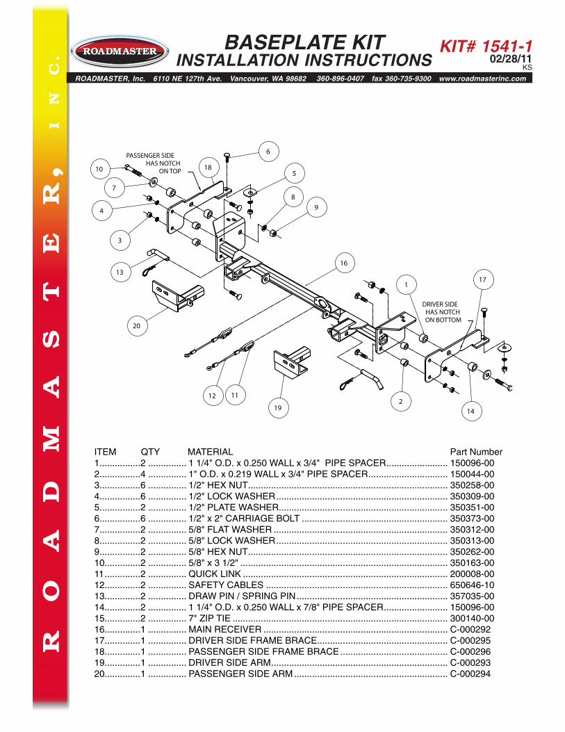
ITEM QTY MATERIAL Part Number 1................2 ............... 1 1/4" O.D. x 0.250 WALL x 3/4" PIPE SPACER ........................ 150096-002................4 ............... 1" O.D. x 0.219 WALL x 3/4" PIPE SPACER ............................... 150044-003................6 ............... 1/2" HEX NUT .............................................................................. 350258-004................6 ............... 1/2" LOCK WASHER ................................................................... 350309-005................2 ............... 1/2" PLATE WASHER.................................................................. 350351-006................6 ............... 1/2" x 2" CARRIAGE BOLT ......................................................... 350373-007................2 ............... 5/8" FLAT WASHER .................................................................... 350312-008................2 ............... 5/8" LOCK WASHER ................................................................... 350313-009................2 ............... 5/8" HEX NUT .............................................................................. 350262-0010..............2 ............... 5/8" x 3 1/2" ................................................................................. 350163-0011 ..............2 ............... QUICK LINK ................................................................................ 200008-0012..............2 ............... SAFETY CABLES ....................................................................... 650646-1013..............2 ............... DRAW PIN / SPRING PIN ........................................................... 357035-0014..............2 ............... 1 1/4" O.D. x 0.250 WALL x 7/8" PIPE SPACER ......................... 150096-0015..............2 ............... 7" ZIP TIE .................................................................................... 300140-0016..............1 ............... MAIN RECEIVER ........................................................................ C-00029217..............1 ............... DRIVER SIDE FRAME BRACE ................................................... C-00029518..............1 ............... PASSENGER SIDE FRAME BRACE .......................................... C-00029619..............1 ............... DRIVER SIDE ARM ..................................................................... C-00029320..............1 ............... PASSENGER SIDE ARM ............................................................ C-000294
ROADMASTER, Inc. 6110 NE 127th Ave. Vancouver, WA 98682 360-896-0407 fax 360-735-9300 www.roadmasterinc.com
BASEPLATE KIT INSTALLATION INSTRUCTIONS
1
2
3
4
5
6
78
9
10
1112
13
14
16
17
18
19
20
DRIVER SIDEHAS NOTCHON BOTTOM
PASSENGER SIDEHAS NOTCH
ON TOP
KIT# 1541-102/28/11
KS
BASEPLATE KIT INSTALLATION INSTRUCTIONS
ROADMASTER, Inc. 6110 NE 127th Ave. Vancouver, WA 98682 360-896-0407 fax 360-735-9300 www.roadmasterinc.com
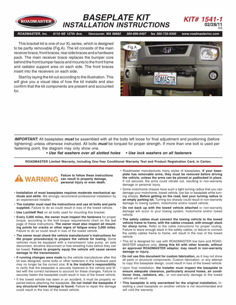
This bracket kit is one of our XL series, which is designed to be partly removable (Fig.A). The kit consists of the main receiver brace, front braces, rear side braces and a hardware pack. The main receiver brace replaces the bumper core behind the front bumper fascia and mounts to the front frame and radiator support area on each side. The front braces insert into the receivers on each side.
Start by laying the kit out according to the illustration. This will give you a visual idea of how the kit installs and also confirm that the kit components are present and accounted for.
Fig.A
IMPORTANT: All baseplates must be assembled with all the bolts left loose for final adjustment and positioning (before tightening) unless otherwise instructed. All bolts must be torqued for proper strength. If more than one bolt is used per fastening point, the diagram may only show one.
• Use flat washers over all slotted holes • Use lock washers on all fasteners
• Installation of most baseplates requires moderate mechanical ap-titude and skills. We strongly recommend professional installation byan experienced installer.
• The installer must read the instructions and use all bolts and partssupplied. Failure to do so could result in loss of the towed vehicle.
• Use Loctite® Red on all bolts used for mounting this bracket.
• Every 3,000 miles, the owner must inspect the fasteners for propertorque, according to the bolt torque requirements chart on the lastpage of these instructions. The owner must also inspect all mount-ing points for cracks or other signs of fatigue every 3,000 miles.Failure to do so could result in loss of the towed vehicle.
• The owner must check the vehicle manufacturer's instructions forthe proper procedure(s) to prepare the vehicle for towing. Somevehicles must be equipped with a transmission lube pump, an axledisconnect, driveline disconnect or free-wheeling hubs before they canbe towed. Failure to properly equip the vehicle will cause severedamage to the transmission.
• If running changes were made by the vehicle manufacturer after thiskit was designed, some bolts or other fasteners in the hardware packmay no longer be the correct size. It is the installer’s responsibilityto verify that the baseplate is securely fastened to the vehicle and fit-ted with the correct hardware to account for these changes. Failure tosecurely fasten the baseplate could result in loss of the towed vehicle.
• If the towed vehicle has been in an accident, it must be properly re-paired before attaching the baseplate. Do not install the baseplate ifany structural frame damage is found. Failure to repair the damagecould result in the loss of the towed vehicle.
ROADMASTER Limited Warranty, including One-Year Conditional Warranty Text and Product Registration Card, in Carton.
• Roadmaster manufactures many styles of baseplates. If your base-plate has removable arms, they must be removed before drivingthe vehicle, unless the arms can be pinned or padlocked in place.If not secured, the arms could vibrate out, resulting in non-warrantydamage or personal injury.
• Some motorhome chassis have such a tight turning radius that you candamage your motorhome, towed vehicle, tow bar or baseplate while turn-ing sharply. Before getting on the road, test your turning radius inan empty parking lot. Turning too sharply could result in non-warrantydamage to towing system, motorhome and/or towed vehicle.
• Do not back up with the towed vehicle attached or non-warrantydamage will occur to your towing system, motorhome and/or towedvehicle.
• The safety cables must connect the towing vehicle to the towedvehicle frame to frame, with the cables crossed, with enough slackfor sharp turns. Refer to the cable instructions for proper routing.Failure to leave enough slack in the safety cables, or failure to connectthe safety cables frame to frame, will result in the loss of the towedvehicle.
• This kit is designed for use with ROADMASTER tow bars and ROAD-MASTER adaptors only. Using this kit with other brands, withoutan approved ROADMASTER adaptor, may result in non-warrantydamage or injury.
• Do not use this document for custom fabrication, as it may not showall parts or structural components. Custom fabrication, or any attemptto copy this baseplate design, could result in loss of the towed vehicle.
• Upon final installation, the installer must inspect the baseplate toensure adequate clearance, particularly around hoses, air condi-tioner lines, radiators, etc., or non-warranty damage to the towedvehicle will result.
• This baseplate is only warranteed for the original installation. In-stalling a used baseplate on another vehicle is not recommended andwill void the warranty.
Failure to follow these instructions can result in property damage, personal injury or even death.WARNING
KIT# 1541-102/28/11
KS
Fig.B Fig.C Fig.D
Fig.GFig.FFig.E
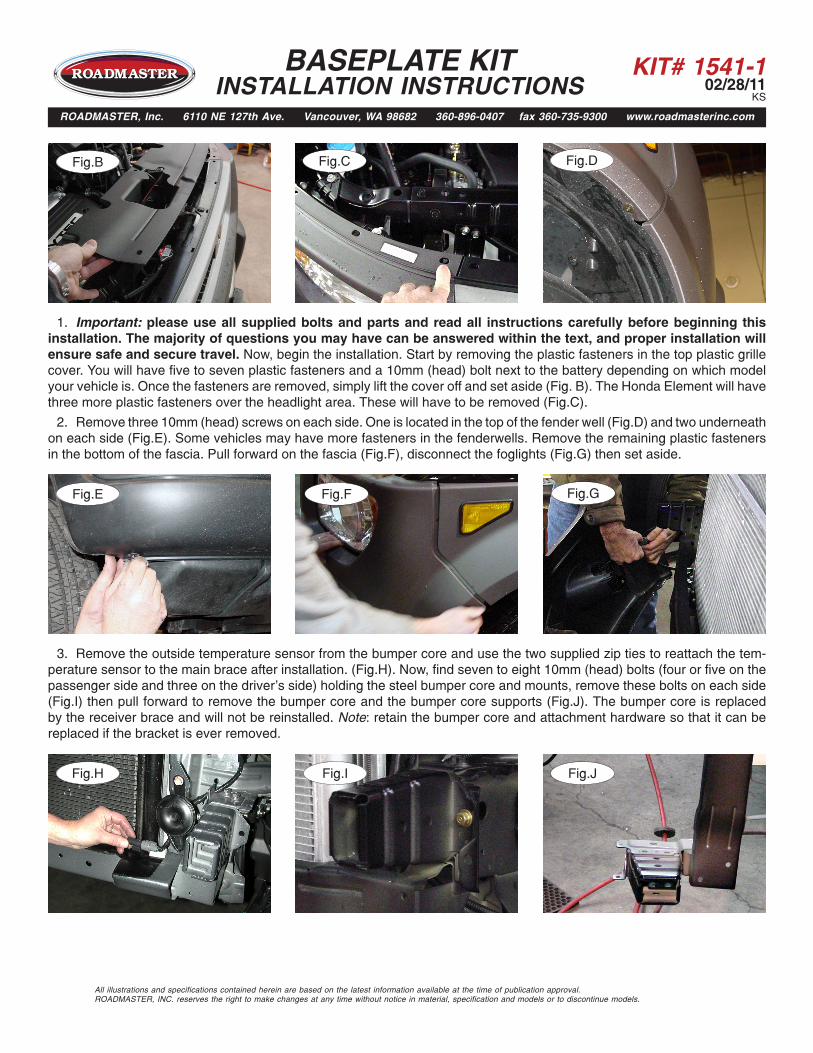
1. Important: please use all supplied bolts and parts and read all instructions carefully before beginning this installation. The majority of questions you may have can be answered within the text, and proper installation will ensure safe and secure travel. Now, begin the installation. Start by removing the plastic fasteners in the top plastic grille cover. You will have five to seven plastic fasteners and a 10mm (head) bolt next to the battery depending on which model your vehicle is. Once the fasteners are removed, simply lift the cover off and set aside (Fig. B). The Honda Element will have three more plastic fasteners over the headlight area. These will have to be removed (Fig.C).
2. Remove three 10mm (head) screws on each side. One is located in the top of the fender well (Fig.D) and two underneath on each side (Fig.E). Some vehicles may have more fasteners in the fenderwells. Remove the remaining plastic fasteners in the bottom of the fascia. Pull forward on the fascia (Fig.F), disconnect the foglights (Fig.G) then set aside.
3. Remove the outside temperature sensor from the bumper core and use the two supplied zip ties to reattach the tem-perature sensor to the main brace after installation. (Fig.H). Now, find seven to eight 10mm (head) bolts (four or five on the passenger side and three on the driver's side) holding the steel bumper core and mounts, remove these bolts on each side (Fig.I) then pull forward to remove the bumper core and the bumper core supports (Fig.J). The bumper core is replaced by the receiver brace and will not be reinstalled. Note: retain the bumper core and attachment hardware so that it can be replaced if the bracket is ever removed.
Fig.I Fig.J
All illustrations and specifications contained herein are based on the latest information available at the time of publication approval. ROADMASTER, INC. reserves the right to make changes at any time without notice in material, specification and models or to discontinue models.
BASEPLATE KIT INSTALLATION INSTRUCTIONS
ROADMASTER, Inc. 6110 NE 127th Ave. Vancouver, WA 98682 360-896-0407 fax 360-735-9300 www.roadmasterinc.com
Fig.H
KIT# 1541-102/28/11
KS
Fig.K Fig.L Fig.M
All illustrations and specifications contained herein are based on the latest information available at the time of publication approval. ROADMASTER, INC. reserves the right to make changes at any time without notice in material, specification and models or to discontinue models.
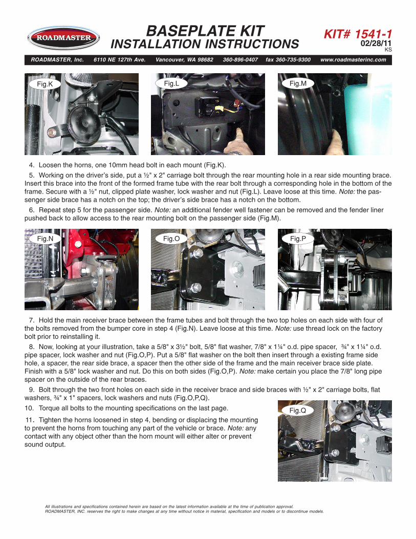
4. Loosen the horns, one 10mm head bolt in each mount (Fig.K).
5. Working on the driver's side, put a ½" x 2" carriage bolt through the rear mounting hole in a rear side mounting brace. Insert this brace into the front of the formed frame tube with the rear bolt through a corresponding hole in the bottom of the frame. Secure with a ½" nut, clipped plate washer, lock washer and nut (Fig.L). Leave loose at this time. Note: the pas-senger side brace has a notch on the top; the driver's side brace has a notch on the bottom.
6. Repeat step 5 for the passenger side. Note: an additional fender well fastener can be removed and the fender liner pushed back to allow access to the rear mounting bolt on the passenger side (Fig.M).
7. Hold the main receiver brace between the frame tubes and bolt through the two top holes on each side with four of the bolts removed from the bumper core in step 4 (Fig.N). Leave loose at this time. Note: use thread lock on the factory bolt prior to reinstalling it.
8. Now, looking at your illustration, take a 5/8" x 3½" bolt, 5/8" flat washer, 7/8" x 1¼" o.d. pipe spacer, ¾" x 1¼" o.d. pipe spacer, lock washer and nut (Fig.O,P). Put a 5/8" flat washer on the bolt then insert through a existing frame side hole, a spacer, the rear side brace, a spacer then the other side of the frame and the main receiver brace side plate. Finish with a 5/8" lock washer and nut. Do this on both sides (Fig.O,P). Note: make certain you place the 7/8" long pipe spacer on the outside of the rear braces.
9. Bolt through the two front holes on each side in the receiver brace and side braces with ½" x 2" carriage bolts, flat washers, ¾" x 1" spacers, lock washers and nuts (Fig.O,P,Q).
Fig.O Fig.PFig.N
Fig.Q10. Torque all bolts to the mounting specifications on the last page.
11. Tighten the horns loosened in step 4, bending or displacing the mounting to prevent the horns from touching any part of the vehicle or brace. Note: any contact with any object other than the horn mount will either alter or prevent sound output.
BASEPLATE KIT INSTALLATION INSTRUCTIONS
ROADMASTER, Inc. 6110 NE 127th Ave. Vancouver, WA 98682 360-896-0407 fax 360-735-9300 www.roadmasterinc.com
KIT# 1541-102/28/11
KS
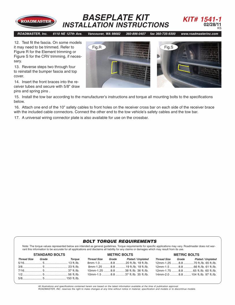
12. Test fit the fascia. On some models it may need to be trimmed. Refer to Figure R for the Element trimming or Figure S for the CRV trimming, if neces-sary.
13. Reverse steps two through four to reinstall the bumper fascia and top cover.
14. Insert the front braces into the re-ceiver tubes and secure with 5/8" draw
Fig.R Fig.S
All illustrations and specifications contained herein are based on the latest information available at the time of publication approval. ROADMASTER, INC. reserves the right to make changes at any time without notice in material, specification and models or to discontinue models.
BOLT TORQUE REQUIREMENTS
METRIC BOLTSThread Size Grade Plated / Unplated12mm-1.25 ........8.8 ............70 ft./lb. 65 ft./lb. 12mm-1.5 ..........8.8 ............66 ft./lb. 61 ft./lb.12mm-1.75 ........8.8 ...........65 ft./lb. 60 ft./lb.14mm-2.0 ..........8.8 .........104 ft./lb. 97 ft./lb.
METRIC BOLTSThread Size Grade Plated / Unplated 8mm-1.0 ............8.8 ............20 ft./lb. 18 ft./lb. 8mm-1.25 .........8.8 ............19 ft./lb. 18 ft./lb.10mm-1.25 ........8.8 ...........38 ft./lb. 36 ft./lb.10mm-1.5 ..........8.8 ...........37 ft./lb. 35 ft./lb.
STANDARD BOLTSThread Size Grade Torque5/16..................... 5 ........................... 13 ft./lb. 3/8....................... 5 ........................... 23 ft./lb.7/16..................... 5 ........................... 37 ft./lb.1/2....................... 5 ........................... 56 ft./lb.5/8....................... 5 ......................... 150 ft./lb.
Note: The torque values represented below are intended as general guidelines. Torque requirements for specific applications may vary. Roadmaster does not war-rant this information to be accurate for all applications and disclaims all liability for any claims or damages which may result from its use.
pins and spring pins .
15. Install the tow bar according to the manufacturer’s instructions and torque all mounting bolts to the specifications below.
16. Attach one end of the 10" safety cables to front holes on the receiver cross bar on each side of the receiver brace with the included cable connectors. Connect the other end to the tow vehicle's safety cables and the tow bar.
17. A universal wiring connector plate is also available for use on the crossbar.
BASEPLATE KIT INSTALLATION INSTRUCTIONS
ROADMASTER, Inc. 6110 NE 127th Ave. Vancouver, WA 98682 360-896-0407 fax 360-735-9300 www.roadmasterinc.com


![10 [Buick Roadmaster 1949]](https://img.dokumen.tips/doc/110x75/55cf96aa550346d0338d0245/10-buick-roadmaster-1949.jpg)