Embed Size (px)
Citation preview
443 06 1522 01 8/30/17Specifications subject to change without notice.
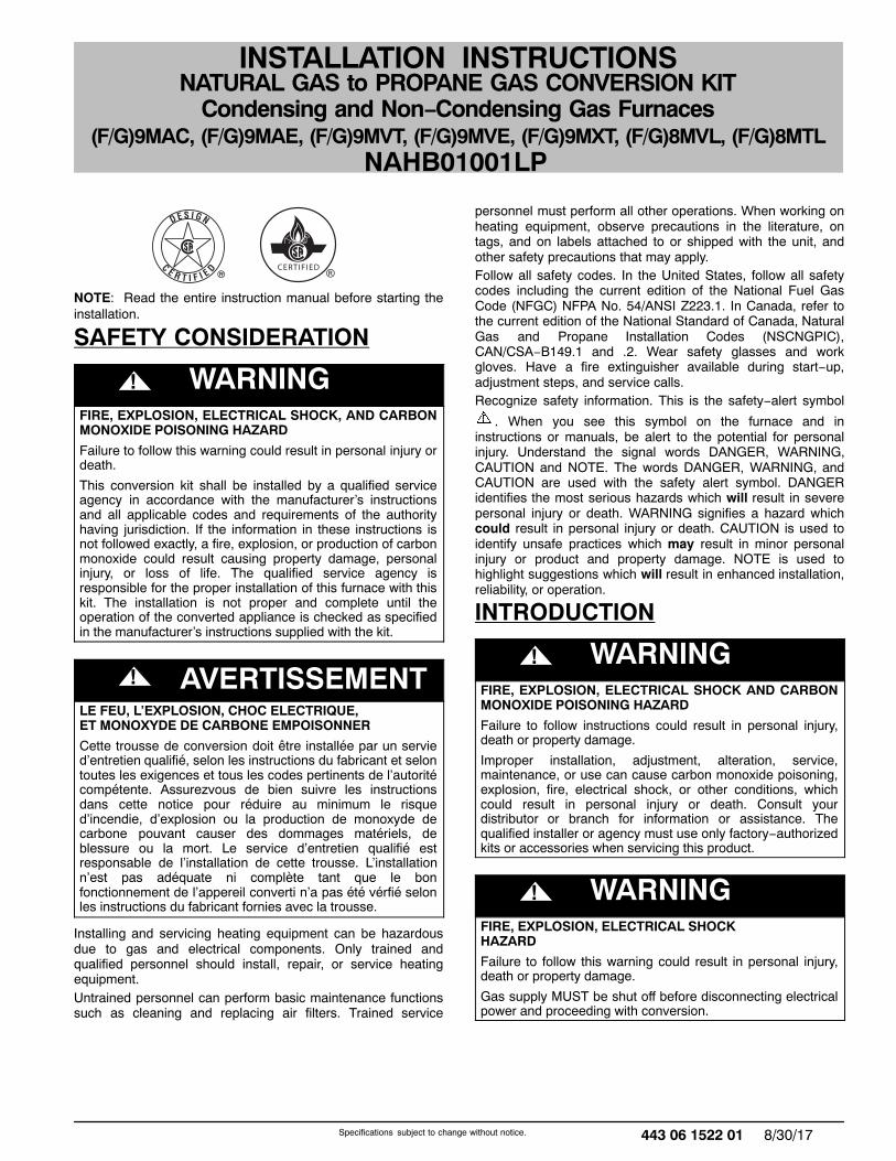
NAHB01001LP
INSTALLATION INSTRUCTIONSNATURAL GAS to PROPANE GAS CONVERSION KIT
Condensing and Non−Condensing Gas Furnaces(F/G)9MAC, (F/G)9MAE, (F/G)9MVT, (F/G)9MVE, (F/G)9MXT, (F/G)8MVL, (F/G)8MTL
CERTIFIED
NOTE: Read the entire instruction manual before starting theinstallation.
SAFETY CONSIDERATION
! WARNINGFIRE, EXPLOSION, ELECTRICAL SHOCK, AND CARBONMONOXIDE POISONING HAZARD
Failure to follow this warning could result in personal injury ordeath.
This conversion kit shall be installed by a qualified serviceagency in accordance with the manufacturer’s instructionsand all applicable codes and requirements of the authorityhaving jurisdiction. If the information in these instructions isnot followed exactly, a fire, explosion, or production of carbonmonoxide could result causing property damage, personalinjury, or loss of life. The qualified service agency isresponsible for the proper installation of this furnace with thiskit. The installation is not proper and complete until theoperation of the converted appliance is checked as specifiedin the manufacturer’s instructions supplied with the kit.
! AVERTISSEMENTLE FEU, L’EXPLOSION, CHOC ELECTRIQUE,ET MONOXYDE DE CARBONE EMPOISONNER
Cette trousse de conversion doit être installée par un servied’entretien qualifié, selon les instructions du fabricant et selontoutes les exigences et tous les codes pertinents de l’autoritécompétente. Assurezvous de bien suivre les instructionsdans cette notice pour réduire au minimum le risqued’incendie, d’explosion ou la production de monoxyde decarbone pouvant causer des dommages matériels, deblessure ou la mort. Le service d’entretien qualifié estresponsable de l’installation de cette trousse. L’installationn’est pas adéquate ni complète tant que le bonfonctionnement de l’appereil converti n’a pas été vérfié selonles instructions du fabricant fornies avec la trousse.
Installing and servicing heating equipment can be hazardousdue to gas and electrical components. Only trained andqualified personnel should install, repair, or service heatingequipment.Untrained personnel can perform basic maintenance functionssuch as cleaning and replacing air filters. Trained service
personnel must perform all other operations. When working onheating equipment, observe precautions in the literature, ontags, and on labels attached to or shipped with the unit, andother safety precautions that may apply.Follow all safety codes. In the United States, follow all safetycodes including the current edition of the National Fuel GasCode (NFGC) NFPA No. 54/ANSI Z223.1. In Canada, refer tothe current edition of the National Standard of Canada, NaturalGas and Propane Installation Codes (NSCNGPIC),CAN/CSA−B149.1 and .2. Wear safety glasses and workgloves. Have a fire extinguisher available during start−up,adjustment steps, and service calls.Recognize safety information. This is the safety−alert symbol
. When you see this symbol on the furnace and ininstructions or manuals, be alert to the potential for personalinjury. Understand the signal words DANGER, WARNING,CAUTION and NOTE. The words DANGER, WARNING, andCAUTION are used with the safety alert symbol. DANGERidentifies the most serious hazards which will result in severepersonal injury or death. WARNING signifies a hazard whichcould result in personal injury or death. CAUTION is used toidentify unsafe practices which may result in minor personalinjury or product and property damage. NOTE is used tohighlight suggestions which will result in enhanced installation,reliability, or operation.
INTRODUCTION
! WARNINGFIRE, EXPLOSION, ELECTRICAL SHOCK AND CARBONMONOXIDE POISONING HAZARD
Failure to follow instructions could result in personal injury,death or property damage.
Improper installation, adjustment, alteration, service,maintenance, or use can cause carbon monoxide poisoning,explosion, fire, electrical shock, or other conditions, whichcould result in personal injury or death. Consult yourdistributor or branch for information or assistance. Thequalified installer or agency must use only factory−authorizedkits or accessories when servicing this product.
! WARNINGFIRE, EXPLOSION, ELECTRICAL SHOCKHAZARD
Failure to follow this warning could result in personal injury,death or property damage.
Gas supply MUST be shut off before disconnecting electricalpower and proceeding with conversion.
2 443 06 1522 01Specifications subject to change without notice.
! WARNINGELECTRICAL SHOCK, FIRE OR EXPLOSION HAZARD
Failure to follow this warning could result in personal injury,death or property damage.
Before installing, modifying, or servicing system, mainelectrical disconnect switch must be in the OFF position andinstall a lockout tag. There may be more than one disconnectswitch. Lock out and tag switch with a suitable warning label.Verify proper operation after servicing.
This instruction covers the installation of gas conversion kit toconvert the following furnaces from natural gas usage topropane gas usage. See appropriate section for your furnacetype.
Section 1—(F/G)9MAC, (F/G)9MAE, (F/G)9MVT, (F/G)9MVE,& (F/G)9MXT 35−in. (889 mm ) 4-Way Multipoise, Hot SurfaceIgnition, Modulating Variable−Speed, Two−StageVariable−Speed and Two−Stage ECM Blower MotorCondensing Furnaces.
Section 2—(F/G)8MVL & (F/G)8MTL, 33.3−in. (846 mm) High,Induced−Combustion, Hot−Surface Ignition, Two-Stage,Variable-Speed, Non-Condensing Furnaces.
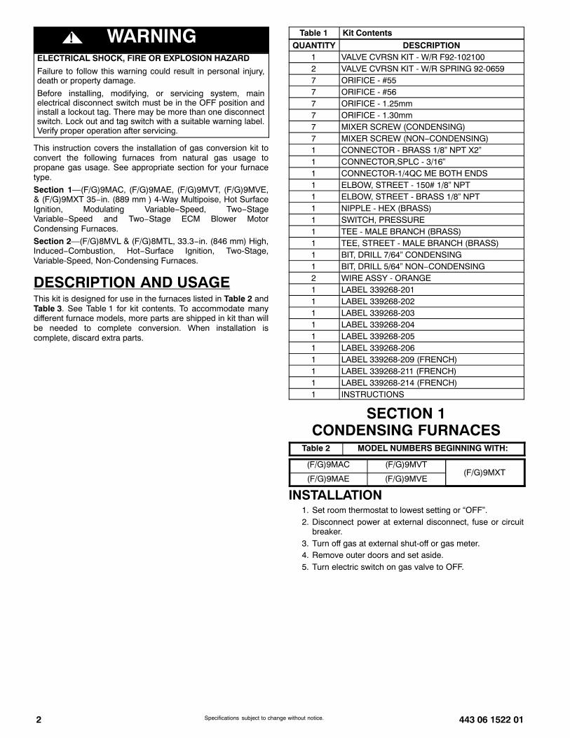
DESCRIPTION AND USAGEThis kit is designed for use in the furnaces listed in Table 2 andTable 3. See Table 1 for kit contents. To accommodate manydifferent furnace models, more parts are shipped in kit than willbe needed to complete conversion. When installation iscomplete, discard extra parts.
Table 1 Kit Contents
QUANTITY DESCRIPTION1 VALVE CVRSN KIT - W/R F92-1021002 VALVE CVRSN KIT - W/R SPRING 92-06597 ORIFICE - #557 ORIFICE - #567 ORIFICE - 1.25mm7 ORIFICE - 1.30mm7 MIXER SCREW (CONDENSING)7 MIXER SCREW (NON−CONDENSING)1 CONNECTOR - BRASS 1/8” NPT X2”1 CONNECTOR,SPLC - 3/16”1 CONNECTOR-1/4QC ME BOTH ENDS1 ELBOW, STREET - 150# 1/8” NPT1 ELBOW, STREET - BRASS 1/8” NPT1 NIPPLE - HEX (BRASS)1 SWITCH, PRESSURE1 TEE - MALE BRANCH (BRASS)1 TEE, STREET - MALE BRANCH (BRASS)1 BIT, DRILL 7/64” CONDENSING1 BIT, DRILL 5/64” NON−CONDENSING2 WIRE ASSY - ORANGE1 LABEL 339268-2011 LABEL 339268-2021 LABEL 339268-2031 LABEL 339268-2041 LABEL 339268-2051 LABEL 339268-2061 LABEL 339268-209 (FRENCH)1 LABEL 339268-211 (FRENCH)1 LABEL 339268-214 (FRENCH)1 INSTRUCTIONS
SECTION 1CONDENSING FURNACES
Table 2 MODEL NUMBERS BEGINNING WITH:
(F/G)9MAC (F/G)9MVT(F/G)9MXT
(F/G)9MAE (F/G)9MVE
INSTALLATION1. Set room thermostat to lowest setting or “OFF”.2. Disconnect power at external disconnect, fuse or circuit
breaker.3. Turn off gas at external shut-off or gas meter.4. Remove outer doors and set aside.5. Turn electric switch on gas valve to OFF.

443 06 1522 01 3Specifications subject to change without notice.
Figure 1 Representative Furnace Drawing
REPRESENTATIVE DRAWING ONLY, SOME MODELS MAY VARY IN APPEARANCE.
REPRESENTATIVE DRAWING ONLY, SOME MODELS MAY VARY IN APPEARANCE.
RATING PLATE NOT SHOWN
(LOCATED ON BLOWER DOOR)
GAS VALVE
MAIN LIMIT SWITCH(BEHIND GAS VALVE)
ELECTRICAL JUNCTION
BOX (IF REQUIRED,
LOCATION MAY VARY)
OPERATING INSTRUCTIONS
NOT SHOWN (LOCATED ON
MAIN FURNACE DOOR, SEE
OPERATING INSTRUCTIONS
INSIDE DOOR FIGURE).
FURNACE
CONTROL
BOARD
MANUAL RESET
ROLLOUT SWITCH
FLAME
SENSOR
MANUAL RESET
ROLLOUT SWITCHGAS BURNER
HOT SURFACE
IGNITER
INDUCER MOTOR
ASSEMBLY
BLOWER AND
MOTOR
CAPACITOR/
POWER CHOKE
BLOWER DOOR
SAFETY SWITCH
A170127
MANIFOLD/ORIFICE/BURNERREMOVAL
! CAUTIONUNIT OPERATION HAZARD
Failure to follow this caution may result in unit damage orimproper operation.
Label all wires prior to disconnection when servicing controls.
! PRUDENCED’EQUIPEMENT D’OPERATION
Toute erreur de câblage peut être une source de danger etde panne.
Lors des opérations d’entretien des commandes, étiquetertous les fils avant de les déconnecter.
NOTE: Use a back-up wrench on the gas valve to prevent thevalve from rotating on the manifold or damaging the mountingto the burner box.
1. Disconnect the gas pipe from gas valve and remove pipefrom the furnace casing.
2. Disconnect the connector harness from gas valve.Disconnect wires from Hot Surface Igniter (HSI) andFlame Sensor.
3. Support the manifold and remove the four (4) screws thatsecure the manifold assembly to the burner box and setaside.
4. Note the location of the green/yellow wire ground wire forre-assembly later. (See Figure 2)
5. Slide one−piece burner assembly out of slots on sides ofburner box. (See Figure 3)
6. Remove the flame sensor from the burner assembly.7. Remove the orifices from the manifold and discard.
Figure 2 Gas Valve with Orifices
Orifice
Connect Green/Yellow
ground wire here
Manifold
Gas Valve
Gas valve must be installed on
manifold with minimum engagement of
6 threads. Cross threading is not
acceptable.
CL
Gas valve is parallel to manifold
within + or - 3˚ Indicated surfaces
to be 90 ˚+ or -2˚
A11486
REPRESENTATIVE DRAWING ONLY, SOME MODELS MAY VARY IN APPREARANCE.
Figure 3 Burner Assembly
FLAME SENSOR(BELOW BURNER)
FLAME ROLLOUTSWITCH
BRACKET, IGNITERIGNITERBURNER SUPT. ASSY
BURNER ASSY
A11403
ORIFICE SELECTION/DERATE
! CAUTIONUNIT DAMAGE HAZARD
Failure to follow this caution may result in unit damage.
DO NOT re−drill burner orifices. Improper drilling may resultin burrs, out−of−round holes, etc. Obtain new orifices if orificesize must be changed. (See Figure 4)
Figure 4 Burner Orifice
BURNER ORIFICE BURNER
ORIFICE
A96249
4 443 06 1522 01Specifications subject to change without notice.
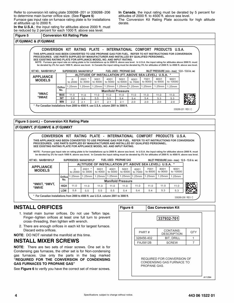
Refer to conversion kit rating plate 339268−201 or 339268−206to determine main burner orifice size. (See Figure 5)Furnace gas input rate on furnace rating plate is for installationsat altitudes up to 2000 ft.In the U.S.A.; the input rating for altitudes above 2000 ft. mustbe reduced by 2 percent for each 1000 ft. above sea level.
In Canada, the input rating must be derated by 5 percent foraltitudes of 2000 ft. to 4500 ft. above sea level.The Conversion Kit Rating Plate accounts for high altitudederate.
Figure 5 Conversion Kit Rating Plate
(F/G)9MAC & (F/G)9MAE
Figure 5 (cont.) − Conversion Kit Rating Plate
(F/G)9MVT, (F/G)9MVE & (F/G)9MXT
INSTALL ORIFICES1. Install main burner orifices. Do not use Teflon tape.
Finger−tighten orifices at least one full turn to preventcross−threading, then tighten with wrench.
2. There are enough orifices in each kit for largest furnace.Discard extra orifices.
NOTE: DO NOT reinstall the manifold at this time.
INSTALL MIXER SCREWSNOTE: There are two sets of mixer screws. One set is forCondensing gas furnaces, the other set is for Non-condensinggas furnaces. Use only the parts in the bag marked“REQUIRED FOR THE CONVERSION OF CONDENSINGGAS FURNACES TO PROPANE GAS”See Figure 6 to verify you have the correct set of mixer screws.
Figure 6 Gas Conversion Kit
A11294
443 06 1522 01 5Specifications subject to change without notice.
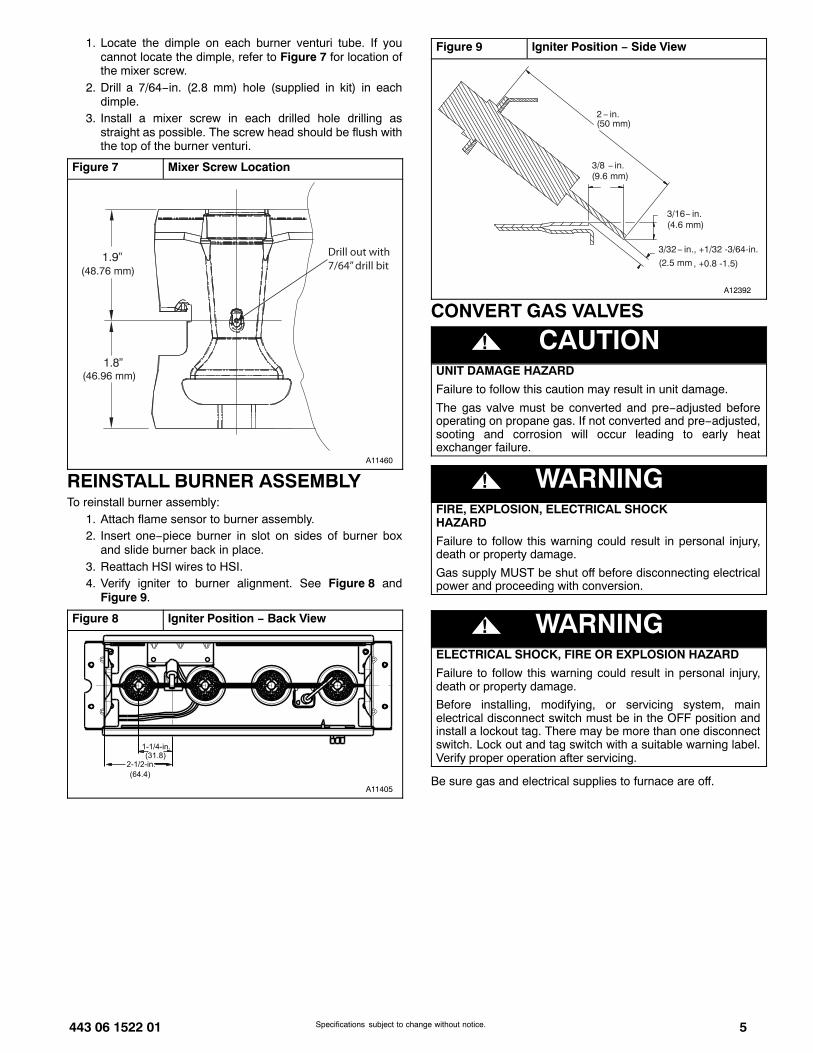
1. Locate the dimple on each burner venturi tube. If youcannot locate the dimple, refer to Figure 7 for location ofthe mixer screw.
2. Drill a 7/64−in. (2.8 mm) hole (supplied in kit) in eachdimple.
3. Install a mixer screw in each drilled hole drilling asstraight as possible. The screw head should be flush withthe top of the burner venturi.
Figure 7 Mixer Screw Location
1.9”(48.76 mm)
1.8”(46.96 mm)
Drill out with7/64” drill bit
A11460
REINSTALL BURNER ASSEMBLYTo reinstall burner assembly:
1. Attach flame sensor to burner assembly.2. Insert one−piece burner in slot on sides of burner box
and slide burner back in place.3. Reattach HSI wires to HSI.4. Verify igniter to burner alignment. See Figure 8 and
Figure 9.
Figure 8 Igniter Position − Back View
2-1/2-in.
(64.4)
1-1/4-in.(31.8)
A11405
Figure 9 Igniter Position − Side View
A12392
2− in.
(2.5 mm
3/8 − in.
3/16− in.
, +0.8 -1.5)
(50 mm)
(9.6 mm)
(4.6 mm)
3/32− in., +1/32 -3/64-in.
CONVERT GAS VALVES
! CAUTIONUNIT DAMAGE HAZARD
Failure to follow this caution may result in unit damage.
The gas valve must be converted and pre−adjusted beforeoperating on propane gas. If not converted and pre−adjusted,sooting and corrosion will occur leading to early heatexchanger failure.
! WARNINGFIRE, EXPLOSION, ELECTRICAL SHOCKHAZARD
Failure to follow this warning could result in personal injury,death or property damage.
Gas supply MUST be shut off before disconnecting electricalpower and proceeding with conversion.
! WARNINGELECTRICAL SHOCK, FIRE OR EXPLOSION HAZARD
Failure to follow this warning could result in personal injury,death or property damage.
Before installing, modifying, or servicing system, mainelectrical disconnect switch must be in the OFF position andinstall a lockout tag. There may be more than one disconnectswitch. Lock out and tag switch with a suitable warning label.Verify proper operation after servicing.
Be sure gas and electrical supplies to furnace are off.
6 443 06 1522 01Specifications subject to change without notice.
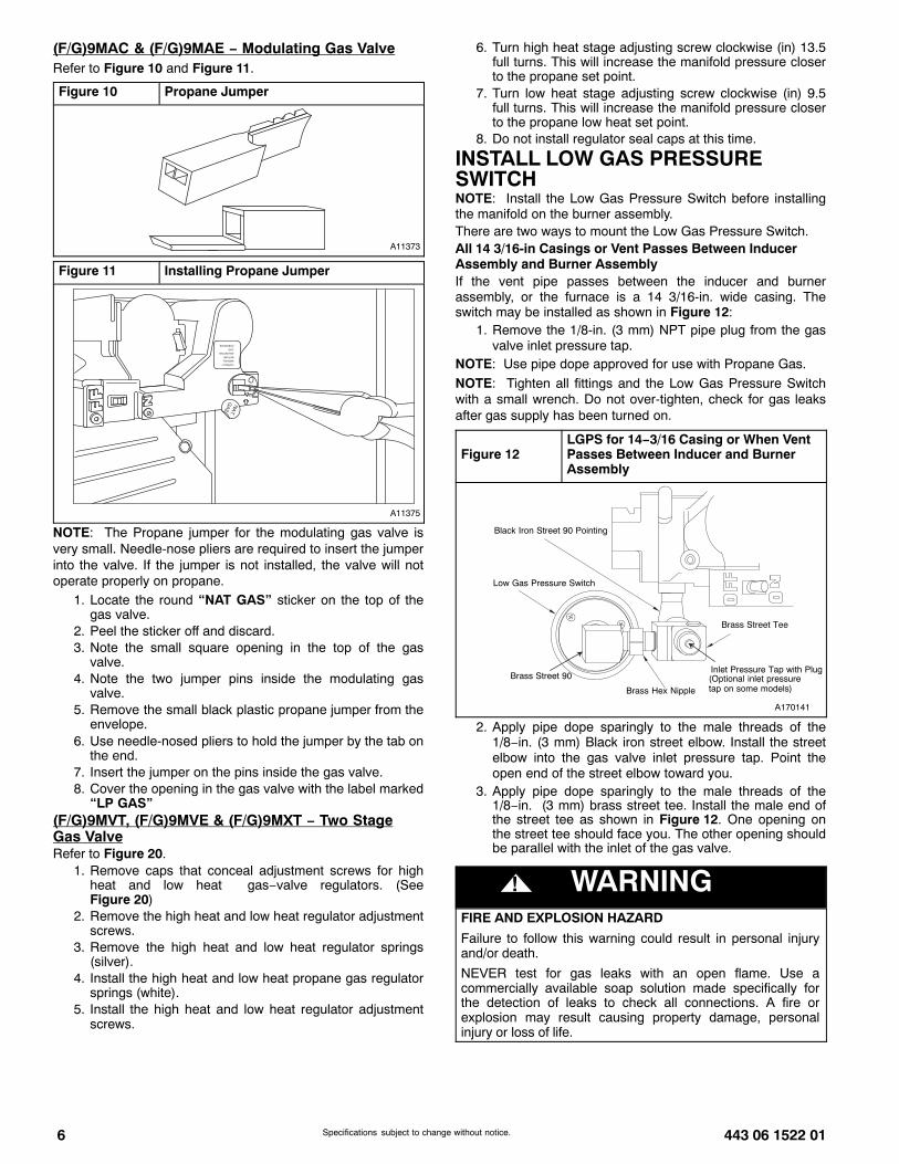
(F/G)9MAC & (F/G)9MAE − Modulating Gas ValveRefer to Figure 10 and Figure 11.
Figure 10 Propane Jumper
A11373
Figure 11 Installing Propane Jumper
A11375
NOTE: The Propane jumper for the modulating gas valve isvery small. Needle-nose pliers are required to insert the jumperinto the valve. If the jumper is not installed, the valve will notoperate properly on propane.
1. Locate the round “NAT GAS” sticker on the top of thegas valve.
2. Peel the sticker off and discard.3. Note the small square opening in the top of the gas
valve.4. Note the two jumper pins inside the modulating gas
valve.5. Remove the small black plastic propane jumper from the
envelope.6. Use needle-nosed pliers to hold the jumper by the tab on
the end.7. Insert the jumper on the pins inside the gas valve.8. Cover the opening in the gas valve with the label marked
“LP GAS”(F/G)9MVT, (F/G)9MVE & (F/G)9MXT − Two StageGas ValveRefer to Figure 20.
1. Remove caps that conceal adjustment screws for highheat and low heat gas−valve regulators. (SeeFigure 20)
2. Remove the high heat and low heat regulator adjustmentscrews.
3. Remove the high heat and low heat regulator springs(silver).
4. Install the high heat and low heat propane gas regulatorsprings (white).
5. Install the high heat and low heat regulator adjustmentscrews.
6. Turn high heat stage adjusting screw clockwise (in) 13.5full turns. This will increase the manifold pressure closerto the propane set point.
7. Turn low heat stage adjusting screw clockwise (in) 9.5full turns. This will increase the manifold pressure closerto the propane low heat set point.
8. Do not install regulator seal caps at this time.
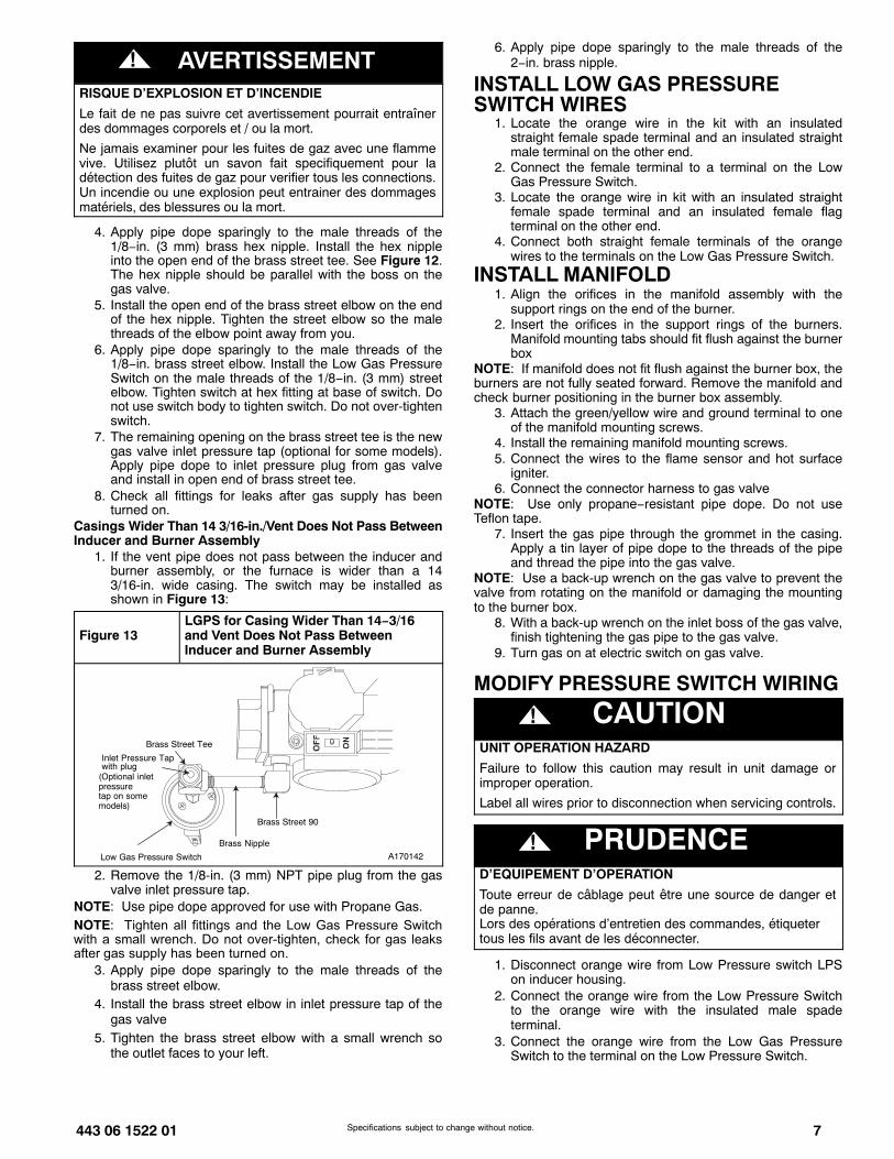
INSTALL LOW GAS PRESSURESWITCHNOTE: Install the Low Gas Pressure Switch before installingthe manifold on the burner assembly.There are two ways to mount the Low Gas Pressure Switch.All 14 3/16-in Casings or Vent Passes Between InducerAssembly and Burner AssemblyIf the vent pipe passes between the inducer and burnerassembly, or the furnace is a 14 3/16-in. wide casing. Theswitch may be installed as shown in Figure 12:
1. Remove the 1/8-in. (3 mm) NPT pipe plug from the gasvalve inlet pressure tap.
NOTE: Use pipe dope approved for use with Propane Gas.
NOTE: Tighten all fittings and the Low Gas Pressure Switchwith a small wrench. Do not over-tighten, check for gas leaksafter gas supply has been turned on.
Figure 12LGPS for 14−3/16 Casing or When VentPasses Between Inducer and BurnerAssembly
Brass Street Tee
Brass Hex Nipple
Brass Street 90
Low Gas Pressure Switch
Black Iron Street 90 Pointing
Inlet Pressure Tap with Plug
A170141
(Optional inlet pressuretap on some models)
2. Apply pipe dope sparingly to the male threads of the1/8−in. (3 mm) Black iron street elbow. Install the streetelbow into the gas valve inlet pressure tap. Point theopen end of the street elbow toward you.
3. Apply pipe dope sparingly to the male threads of the1/8−in. (3 mm) brass street tee. Install the male end ofthe street tee as shown in Figure 12. One opening onthe street tee should face you. The other opening shouldbe parallel with the inlet of the gas valve.
! WARNINGFIRE AND EXPLOSION HAZARD
Failure to follow this warning could result in personal injuryand/or death.
NEVER test for gas leaks with an open flame. Use acommercially available soap solution made specifically forthe detection of leaks to check all connections. A fire orexplosion may result causing property damage, personalinjury or loss of life.
443 06 1522 01 7Specifications subject to change without notice.
! AVERTISSEMENTRISQUE D’EXPLOSION ET D’INCENDIE
Le fait de ne pas suivre cet avertissement pourrait entraînerdes dommages corporels et / ou la mort.
Ne jamais examiner pour les fuites de gaz avec une flammevive. Utilisez plutôt un savon fait specifiquement pour ladétection des fuites de gaz pour verifier tous les connections.Un incendie ou une explosion peut entrainer des dommagesmatériels, des blessures ou la mort.
4. Apply pipe dope sparingly to the male threads of the1/8−in. (3 mm) brass hex nipple. Install the hex nippleinto the open end of the brass street tee. See Figure 12.The hex nipple should be parallel with the boss on thegas valve.
5. Install the open end of the brass street elbow on the endof the hex nipple. Tighten the street elbow so the malethreads of the elbow point away from you.
6. Apply pipe dope sparingly to the male threads of the1/8−in. brass street elbow. Install the Low Gas PressureSwitch on the male threads of the 1/8−in. (3 mm) streetelbow. Tighten switch at hex fitting at base of switch. Donot use switch body to tighten switch. Do not over-tightenswitch.
7. The remaining opening on the brass street tee is the newgas valve inlet pressure tap (optional for some models).Apply pipe dope to inlet pressure plug from gas valveand install in open end of brass street tee.
8. Check all fittings for leaks after gas supply has beenturned on.
Casings Wider Than 14 3/16-in./Vent Does Not Pass BetweenInducer and Burner Assembly
1. If the vent pipe does not pass between the inducer andburner assembly, or the furnace is wider than a 143/16-in. wide casing. The switch may be installed asshown in Figure 13:
Figure 13LGPS for Casing Wider Than 14−3/16and Vent Does Not Pass BetweenInducer and Burner Assembly
Brass Street 90
Brass Nipple
Low Gas Pressure Switch
Inlet Pressure Tap
Brass Street Tee
with plug
A170142
(Optional inletpressuretap on somemodels)
2. Remove the 1/8-in. (3 mm) NPT pipe plug from the gasvalve inlet pressure tap.
NOTE: Use pipe dope approved for use with Propane Gas.NOTE: Tighten all fittings and the Low Gas Pressure Switchwith a small wrench. Do not overtighten, check for gas leaksafter gas supply has been turned on.
3. Apply pipe dope sparingly to the male threads of thebrass street elbow.
4. Install the brass street elbow in inlet pressure tap of thegas valve
5. Tighten the brass street elbow with a small wrench sothe outlet faces to your left.
6. Apply pipe dope sparingly to the male threads of the2−in. brass nipple.
INSTALL LOW GAS PRESSURESWITCH WIRES
1. Locate the orange wire in the kit with an insulatedstraight female spade terminal and an insulated straightmale terminal on the other end.
2. Connect the female terminal to a terminal on the LowGas Pressure Switch.
3. Locate the orange wire in kit with an insulated straightfemale spade terminal and an insulated female flagterminal on the other end.
4. Connect both straight female terminals of the orangewires to the terminals on the Low Gas Pressure Switch.
INSTALL MANIFOLD1. Align the orifices in the manifold assembly with the
support rings on the end of the burner.2. Insert the orifices in the support rings of the burners.
Manifold mounting tabs should fit flush against the burnerbox
NOTE: If manifold does not fit flush against the burner box, theburners are not fully seated forward. Remove the manifold andcheck burner positioning in the burner box assembly.
3. Attach the green/yellow wire and ground terminal to oneof the manifold mounting screws.
4. Install the remaining manifold mounting screws.5. Connect the wires to the flame sensor and hot surface
igniter.6. Connect the connector harness to gas valve
NOTE: Use only propane−resistant pipe dope. Do not useTeflon tape.
7. Insert the gas pipe through the grommet in the casing.Apply a tin layer of pipe dope to the threads of the pipeand thread the pipe into the gas valve.
NOTE: Use a back-up wrench on the gas valve to prevent thevalve from rotating on the manifold or damaging the mountingto the burner box.
8. With a back-up wrench on the inlet boss of the gas valve,finish tightening the gas pipe to the gas valve.
9. Turn gas on at electric switch on gas valve.
MODIFY PRESSURE SWITCH WIRING
! CAUTIONUNIT OPERATION HAZARD
Failure to follow this caution may result in unit damage orimproper operation.
Label all wires prior to disconnection when servicing controls.
! PRUDENCED’EQUIPEMENT D’OPERATION
Toute erreur de câblage peut être une source de danger etde panne.Lors des opérations d’entretien des commandes, étiquetertous les fils avant de les déconnecter.
1. Disconnect orange wire from Low Pressure switch LPSon inducer housing.
2. Connect the orange wire from the Low Pressure Switchto the orange wire with the insulated male spadeterminal.
3. Connect the orange wire from the Low Gas PressureSwitch to the terminal on the Low Pressure Switch.
8 443 06 1522 01Specifications subject to change without notice.
4. Route orange wires along wire harness. If possible,secure with wire tie provided in kit.
CHECK INLET GAS PRESSURE
! CAUTIONUNIT DAMAGE HAZARD
Failure to follow this caution may result in unit damage.
DO NOT operate furnace more than one minute to checkinlet gas pressure, as conversion is not complete at this time.
NOTE: This kit is to be used only when inlet gas pressure isbetween 12.0−in. w.c. and 13.6−in. w.c.
1. On some models, remove the 1/8−in. (3 mm) plug frominlet the pressure tap and insert pressure tap (seeFigure 12 and Figure 13). Or, on some models, loosenthe set screw on inlet tower pressure tap no more thanon full turn with a 3/32−in. hex wrench. (See Figure 18)
2. Verify manometer is connected to inlet pressure tap ongas valve. (See Figure 12 or Figure 13, or Figure 18)
3. Turn on furnace power supply.4. Turn gas supply manual shutoff valve to ON position.5. Turn furnace gas valve switch to ON position.
! WARNINGFIRE, EXPLOSION, ELECTRICAL SHOCK HAZARD
Failure to follow this warning could result in personal injury,death or property damage.
Gas supply MUST be shut off before disconnecting electricalpower and proceeding with conversion.
! WARNINGELECTRICAL SHOCK, FIRE OR EXPLOSION HAZARDFailure to follow this warning could result in personal injury,death or property damage.Before installing, modifying, or servicing system, mainelectrical disconnect switch must be in the OFF position andinstall a lockout tag. There may be more than one disconnectswitch. Lock out and tag switch with a suitable warning label.Verify proper operation after servicing.
(F/G)9MAC & (F/G)9MAE − Modulating Gas Valve1. Turn Setup Switch SW1−2 on furnace control ON (see
Figure 14).2. Jumper R−W/W1 and R−W2 thermostat connections on
control.3. When main burners ignite, confirm inlet gas pressure is
between 12.0−in. w.c. and 13.6−in. w.c.4. Remove jumper across R−W/W1 and R−W2 thermostat
connections to terminate call for heat.5. Turn furnace gas valve switch to OFF position.6. Turn gas supply manual shutoff valve to OFF position.7. Turn off furnace power supply.
8. Remove manometer and on some models removepressure tap fitting.
9. On some models, apply pipe dope sparingly to the end ofinlet gas pipe plug and install into unused end of 1/8−in.(3 mm) tee. Use a small back−up wrench on tee whentightening gas inlet pipe plug. Or, on some models,tighten set screw on inlet tower pressure tap with a3/32−in. hex wrench. (See Figure 12 or Figure 13, orFigure 18)
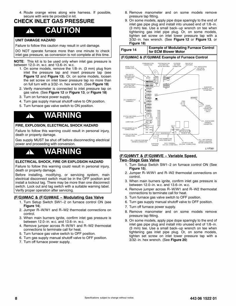
Figure 14 Example of Modulating Furnace Controlfor ECM Blower Motor
(F/G)9MAC & (F/G)9MAE Example of Furnace Control
24-V THERMOSTAT TERMINALS
PL2 – HOT SURFACE IGNITER & INDUCER
MOTOR CONNECTOR
115-VAC (L2) NEUTRAL CONNECTIONS
115-VAC (L1) LINE VOLTAGE CONNECTIONS
EAC-1 TERMINAL (115-VAC 1.0 AMP MAX.)
PL1 – LOW VOLTAGE MAIN HARNESS CONNECTOR
PL3 – ECM BLOWER HARNESS
CONNECTOR
TRANSFORMER 24-VAC CONNECTIONS
3-AMP FUSE
STATUS AND COMM LED LIGHTS
SW1 SETUP SWITCHES AND BLOWER OFF-
DELAY
MODEL PLUG CONNECTOR
AIR CONDITIONING (A/C) AIRFLOW
SETUP SWITCHES
COMMUNICATION CONNECTOR
CONTINUOUS FAN (CF) AIRFLOW
SETUP SWITCHES
OUTDOOR AIR TEMP
CONNECTOR
HUMIDIFIER TERMINAL (24-VAC
0.5 AMP MAX.
FLASH UPGRADE
CONNECTOR (FACTORY
ONLY)
SW4 SETUP SWITCHES
SOFTWARE VERSION
PART NUMBER AND DATE CODE WWYY
PL8 - MODULATING GAS VALVE
CONNECTOR
L11F061
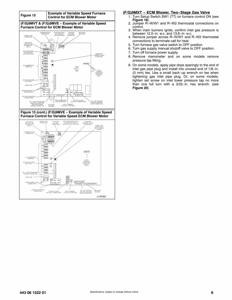
(F/G)9MVT & (F/G)9MVE − Variable Speed,Two−Stage Gas Valve
1. Turn Setup Switch SW1−2 on furnace control ON (SeeFigure 15).
2. Jumper R−W/W1 and R−W2 thermostat connections oncontrol.
3. When main burners ignite, confirm inlet gas pressure isbetween 12.0−in. w.c. and 13.6−in. w.c.
4. Remove jumper across R−W/W1 and R−W2 thermostatconnections to terminate call for heat.
5. Turn furnace gas valve switch to OFF position.6. Turn gas supply manual shutoff valve to OFF position.7. Turn off furnace power supply.8. Remove manometer and on some models remove
pressure tap fitting.9. On some models, apply pipe dope sparingly to the end of
inlet gas pipe plug and install into unused end of 1/8−in.(3 mm) tee. Use a small back−up wrench on tee whentightening gas inlet pipe plug. Or, on some models,tighten set screw on inlet tower pressure tap with a3/32−in. hex wrench. (See Figure 20)
443 06 1522 01 9Specifications subject to change without notice.
Figure 15 Example of Variable Speed FurnaceControl for ECM Blower Motor
(F/G)9MVT & (F/G)9MVE − Example of Variable SpeedFurnace Control for ECM Blower Motor
24-V THERMOSTAT TERMINALS
PL2 – HOT SURFACE IGNITER & INDUCER
MOTOR CONNECTOR
115-VAC (L2) NEUTRAL CONNECTIONS
115-VAC (L1) LINE VOLTAGE CONNECTIONS
EAC-1 TERMINAL (115-VAC 1.0 AMP MAX.)
PL1 – LOW VOLTAGE MAIN HARNESS CONNECTOR
AND ECM BLOWER HARNESS CONNECTOR
TRANSFORMER 24-VAC CONNECTIONS
3-AMP FUSE
STATUS AND COMM LED LIGHTS
SW1 SETUP SWITCHES AND BLOWER OFF-
DELAY
MODEL PLUG CONNECTOR
AIR CONDITIONING (A/C) AIRFLOW
SETUP SWITCHES
COMMUNICATION CONNECTOR
CONTINUOUS FAN (CF) AIRFLOW
SETUP SWITCHES
OUTDOOR AIR TEMP
CONNECTOR
HUMIDIFIER TERMINAL (24-VAC
0.5 AMP MAX.
FLASH UPGRADE
CONNECTOR (FACTORY
ONLY)
SW4 SETUP SWITCHES
SOFTWARE VERSION
PART NUMBER AND DATE CODE WWYY
Figure 15 (cont.) (F/G)9MVE − Example of Variable SpeedFurnace Control for Variable Speed ECM Blower Motor
L14F003
24-V THERMOSTAT TERMINALS
PL2 – HOT SURFACE IGNITER & INDUCER
MOTOR CONNECTOR
115-VAC (L2) NEUTRAL CONNECTIONS 115-VAC (L1) LINE
VOLTAGE CONNECTIONS EAC-1 TERMINAL
(115-VAC 1.0 AMP MAX.)
PL1 – LOW VOLTAGE MAIN HARNESS CONNECTOR
TRANSFORMER 24-VAC CONNECTIONS
3-AMP FUSE
STATUS AND COMM LED LIGHTS
SW1 SETUP SWITCHES AND BLOWER OFF-
DELAY
MODEL PLUG CONNECTOR
COMMUNICATION CONNECTOR
AIR CONDITIONING (A/C) & CONTINUOUS FAN (CF)
AIRFLOW SETUP SWITCHES
OUTDOOR AIR TEMP
CONNECTOR
HUMIDIFIER TERMINAL (24-VAC
0.5 AMP MAX.) ACRDJ – AIR
CONDITIONING RELAY DISABLE
JUMPER
FLASHUPGRADE
CONNECTOR (FACTORY
ONLY)
SOFTWARE VERSION
(F/G)9MXT − ECM Blower, Two−Stage Gas Valve1. Turn Setup Switch SW1 (TT) on furnace control ON (see
Figure 16).2. Jumper R−W/W1 and R−W2 thermostat connections on
control.3. When main burners ignite, confirm inlet gas pressure is
between 12.0−in. w.c. and 13.6−in. w.c.4. Remove jumper across R−W/W1 and R−W2 thermostat
connections to terminate call for heat.5. Turn furnace gas valve switch to OFF position.6. Turn gas supply manual shutoff valve to OFF position.7. Turn off furnace power supply.8. Remove manometer and on some models remove
pressure tap fitting.9. On some models, apply pipe dope sparingly to the end of
inlet gas pipe plug and install into unused end of 1/8−in.(3 mm) tee. Use a small back−up wrench on tee whentightening gas inlet pipe plug. Or, on some models,tighten set screw on inlet tower pressure tap no morethan one full turn with a 3/32−in. hex wrench. (seeFigure 20)
10 443 06 1522 01Specifications subject to change without notice.
Figure 16 (F/G)9MXT − Example of Two−Stage Furnace Control
TEST / TWIN
HUM
PLT
PL1
W2 Y
1 DH
UM
G C
OM
W/W
1 Y/Y
2 R24V
FUSE 3−AMP
EAC−2
EAC−1
L1 BL−1 XFMR
L2
COM
HI HT
COOL
LO H T
SPARE 124V
MT
RT
AP
S
BLOWER SPEEDTERMINALS
115−VAC (L2)NEUTRALCONNECTIONS
LED OPERATION& DIAGNOSTIC LIGHT
3−AMP FUSE
24−V THERMOS TATTERMINALS
SET UP SWITCHESTHERMOSTAT TYPE (TT)AND HEAT OFF−DELAY
TWINNING AND/ORCOMPONENT TESTTERMINAL
HUMIDIFIER TERMINAL(24 VAC 0.5 AMPS MAX)
TRANSFORMER24 VAC CONNECTIONS
P−1 LOW VOLTAGE
P2 − HOT SURFACEIGNITER/INDUCE RMOTOR CONNECTION
115 VACBLOWER POWER (BL1)CONNECTION
115 VAC LINE (L1)INPUT
TTOFFDLY
ON
OF
F
1 2 3
IDR
HS
IR IDM
IHI/L
OR
PL
21
HSI HI LO
1
EAC TERMINAL115 VAC 1.0 AMPMAX
115 VACTRANSFORMERPRIMARY
SPARE 2
ÎÎÎÎÎÎÎÎÎÎÎÎÎÎÎÎÎÎÎÎÎÎÎÎÎÎÎÎÎÎÎÎÎÎÎÎÎÎÎÎÎÎÎÎÎÎÎÎÎÎÎÎÎÎÎÎÎÎÎÎÎÎÎÎÎÎÎÎÎÎÎÎÎÎÎÎÎÎÎÎÎÎÎÎÎÎÎÎÎÎÎÎÎÎÎÎÎÎÎÎÎÎÎÎÎÎÎÎÎÎÎÎÎÎÎÎÎÎÎÎÎÎÎÎÎÎÎÎÎÎÎÎÎÎÎÎÎÎÎÎÎÎÎÎÎÎÎÎÎÎÎÎÎÎ
HUM
115 VAC HUM
COM/BLUE 24VAC/RED
CO
M24
V
24VAC
! WARNINGFIRE, EXPLOSION, ELECTRICAL SHOCKHAZARD
Failure to follow this warning could result in personal injury,death or property damage.
Gas supply MUST be shut off before disconnecting electricalpower and proceeding with conversion.
! WARNINGELECTRICAL SHOCK, FIRE OR EXPLOSION HAZARD
Failure to follow this warning could result in personal injury,death or property damage.
Before installing, modifying, or servicing system, mainelectrical disconnect switch must be in the OFF position andinstall a lockout tag. There may be more than one disconnectswitch. Lock out and tag switch with a suitable warning label.Verify proper operation after servicing.
CHECK FURNACE AND MAKEADJUSTMENTS
1. Be sure main gas and electric supplies to furnace are off.2. On some models, remove 1/8-in. (3 mm) pipe plug from
manifold pressure tap on the outlet end of gas valve andinsert pressure tap. Or, on some models, loosen setscrew on manifold tower pressure tap no more than onefull turn with a 3/32−in. hex wrench.
3. Attach manometer to manifold pressure tap on gasvalve. (see Figure 18 or Figure 20)
4. Turn gas supply manual shutoff valve to ON position.5. Turn furnace gas valve switch to ON position.
6. Check all threaded pipe connections for gas leaks.7. Turn on furnace power supply.
! WARNINGFIRE AND EXPLOSION HAZARD
Failure to follow this warning could result in personal injuryand/or death.
NEVER test for gas leaks with an open flame. Use acommercially available soap solution made specifically forthe detection of leaks to check all connections. A fire orexplosion may result causing property damage, personalinjury or loss of life.
! AVERTISSEMENTRISQUE D’EXPLOSION ET D’INCENDIE
Le fait de ne pas suivre cet avertissement pourrait entraînerdes dommages corporels et / ou la mort.
Ne jamais examiner pour les fuites de gaz avec une flammevive. Utilisez plutôt un savon fait specifiquement pour ladétection des fuites de gaz pour verifier tous les connections.Un incendie ou une explosion peut entrainer des dommagesmatériels, des blessures ou la mort.
GAS INPUT RATE INFORMATIONThe gas input rate for propane is the same as for natural gas.See furnace rating plate on blower door for input rate. The inputrate for propane is determined by manifold pressure and orificesize.The gas valve must be set for Maximum Heat first and then setfor Minimum heat on Modulating furnaces. The gas valve mustbe set for High Heat first and then set for Low Heat on

443 06 1522 01 11Specifications subject to change without notice.
Two−Stage gas valve furnaces. Furnace gas input rate onrating plate is for installations at altitudes up to 2000 ft. (610 M).In the U.S.A., the input rating for altitudes above 2000 ft.(610M) must be reduced by 2 percent for each 1000 ft. (305 M)above sea level.In Canada, the input rating must be derated by 5 percent foraltitudes of 2000 ft. (610 M) to 4500 ft. (1372 M) above sealevel.The Conversion Kit Rating Plate accounts for high altitudederate.
SET GAS INPUT RATEFigure 17 Burner Flame
Burner Flame
Burner
Manifold
A11461
(F/G)9MAC & (F/G)9MAE − Modulating Gas Valve
Figure 18 Automatic Control Valve (Modulating)without Tower Pressure Ports
(F/G)9MAC & (F/G)9MAE
ON/OFF Switch
1/2” NPT Outlet
ManifoldPressure Tap
InletPressure Tap
Min/Max Heat Adust(Under Cap)
GAS FLOW
MODULATING
Turn screw 1 click persecond to adjust rate. Clockwise to increaserate, counter clockwiseto decrease rate.
A10496
Figure 18 (cont.) − (F/G)9MAC & (F/G)9MAE − AutomaticControl Valve (Modulating) with Tower Pressure Ports
A170116
OUTP
ON/OFF SWITCH
MANIFOLD PRESSURE TAPSET SCREW: 3/32” HEX HEAD
ACCEPTS 5/16” HOSECONNECTION
1/2” NPTINLET
1/2” NPTOUTLET
INLET PRESSURE TAPSET SCREW:3/32” HEX HEADACCEPTS 5/16” HOSECONNECTION
MIN/MAX HEATADJUST (UNDER CAP)
Representative drawing only, some models may vary in appearance.
A170131
1/2” NPTINLET 1/2” NPT
OUTLET
INP
1/8” NPT INLETPRESSURE TAP
Representative drawing only, some models may vary in appearance.
! CAUTIONUNIT DAMAGE HAZARD
Failure to follow this caution may result in gas valve damage.
Do not force the rotary adjustment switch on the modulatinggas valve. Do not turn the rotary adjustment switch fasterthan one click per second when adjusting manifold pressure.Gas valve will be damaged if excessive force is used on therotary switch.
For proper operation and long term reliability, the manifoldpressure must be adjusted as specified on the conversion kitrating plate.The modulating furnace manifold pressure is set at two points.The first point is Maximum Heat. The second point is MinimumHeat. Do not adjust Intermediate Heat manifold pressure.Intermediate Heat manifold pressure can be checked as part ofthe temperature rise, but is not adjustable. Always adjustMaximum Heat first, then Minimum Heat.NOTE: DO NOT set Maximum Heat manifold pressure lessthan 10.5-in. w.c. or more than 11-in. w.c. for propane gas.
NOTE: Use care when performing adjustments. Gas valveadjustment is performed by turning a rotary adjustment switchinside the gas valve with a small straight blade screwdriver.Excessive force can break or bend the rotary adjustment switchmaking it non−adjustable.
12 443 06 1522 01Specifications subject to change without notice.
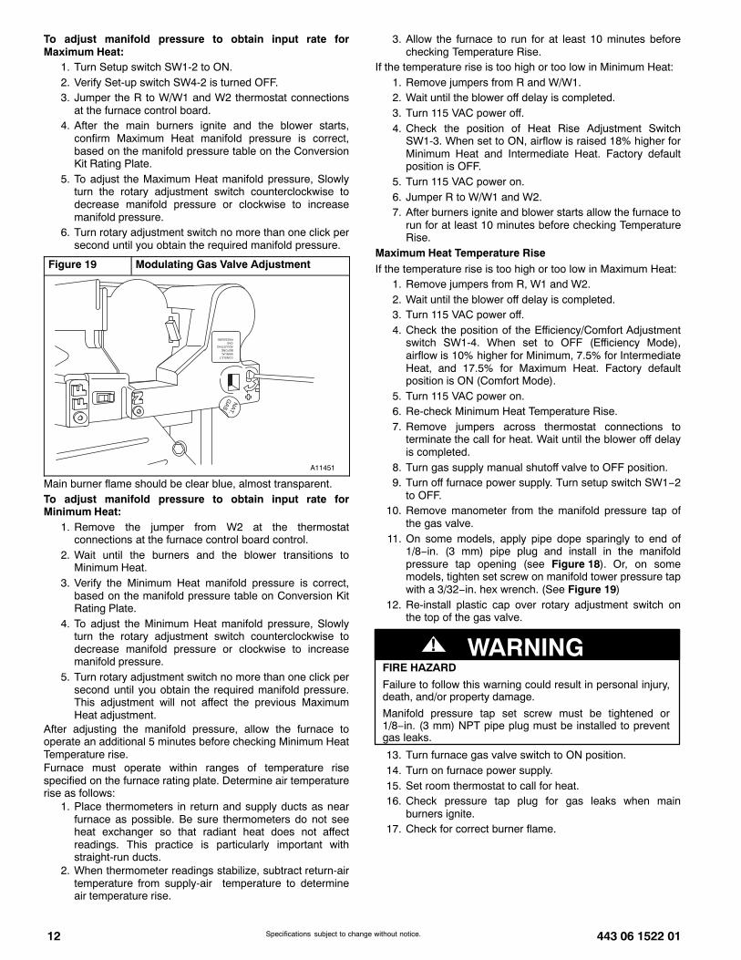
To adjust manifold pressure to obtain input rate forMaximum Heat:
1. Turn Setup switch SW1-2 to ON.2. Verify Set-up switch SW4-2 is turned OFF.3. Jumper the R to W/W1 and W2 thermostat connections
at the furnace control board.4. After the main burners ignite and the blower starts,
confirm Maximum Heat manifold pressure is correct,based on the manifold pressure table on the ConversionKit Rating Plate.
5. To adjust the Maximum Heat manifold pressure, Slowlyturn the rotary adjustment switch counterclockwise todecrease manifold pressure or clockwise to increasemanifold pressure.
6. Turn rotary adjustment switch no more than one click persecond until you obtain the required manifold pressure.
Figure 19 Modulating Gas Valve Adjustment
A11451
Main burner flame should be clear blue, almost transparent.To adjust manifold pressure to obtain input rate forMinimum Heat:
1. Remove the jumper from W2 at the thermostatconnections at the furnace control board control.
2. Wait until the burners and the blower transitions toMinimum Heat.
3. Verify the Minimum Heat manifold pressure is correct,based on the manifold pressure table on Conversion KitRating Plate.
4. To adjust the Minimum Heat manifold pressure, Slowlyturn the rotary adjustment switch counterclockwise todecrease manifold pressure or clockwise to increasemanifold pressure.
5. Turn rotary adjustment switch no more than one click persecond until you obtain the required manifold pressure.This adjustment will not affect the previous MaximumHeat adjustment.
After adjusting the manifold pressure, allow the furnace tooperate an additional 5 minutes before checking Minimum HeatTemperature rise.Furnace must operate within ranges of temperature risespecified on the furnace rating plate. Determine air temperaturerise as follows:
1. Place thermometers in return and supply ducts as nearfurnace as possible. Be sure thermometers do not seeheat exchanger so that radiant heat does not affectreadings. This practice is particularly important withstraight-run ducts.
2. When thermometer readings stabilize, subtract return-airtemperature from supply-air temperature to determineair temperature rise.
3. Allow the furnace to run for at least 10 minutes beforechecking Temperature Rise.
If the temperature rise is too high or too low in Minimum Heat:1. Remove jumpers from R and W/W1.2. Wait until the blower off delay is completed.3. Turn 115 VAC power off.4. Check the position of Heat Rise Adjustment Switch
SW1-3. When set to ON, airflow is raised 18% higher forMinimum Heat and Intermediate Heat. Factory defaultposition is OFF.
5. Turn 115 VAC power on.6. Jumper R to W/W1 and W2.7. After burners ignite and blower starts allow the furnace to
run for at least 10 minutes before checking TemperatureRise.
Maximum Heat Temperature RiseIf the temperature rise is too high or too low in Maximum Heat:
1. Remove jumpers from R, W1 and W2.2. Wait until the blower off delay is completed.3. Turn 115 VAC power off.4. Check the position of the Efficiency/Comfort Adjustment
switch SW1-4. When set to OFF (Efficiency Mode),airflow is 10% higher for Minimum, 7.5% for IntermediateHeat, and 17.5% for Maximum Heat. Factory defaultposition is ON (Comfort Mode).
5. Turn 115 VAC power on.6. Re-check Minimum Heat Temperature Rise.7. Remove jumpers across thermostat connections to
terminate the call for heat. Wait until the blower off delayis completed.
8. Turn gas supply manual shutoff valve to OFF position.9. Turn off furnace power supply. Turn setup switch SW1−2
to OFF.10. Remove manometer from the manifold pressure tap of
the gas valve.11. On some models, apply pipe dope sparingly to end of
1/8−in. (3 mm) pipe plug and install in the manifoldpressure tap opening (see Figure 18). Or, on somemodels, tighten set screw on manifold tower pressure tapwith a 3/32−in. hex wrench. (See Figure 19)
12. Re-install plastic cap over rotary adjustment switch onthe top of the gas valve.
FIRE HAZARD
Failure to follow this warning could result in personal injury,death, and/or property damage.
Manifold pressure tap set screw must be tightened or1/8−in. (3 mm) NPT pipe plug must be installed to preventgas leaks.
! WARNING
13. Turn furnace gas valve switch to ON position.14. Turn on furnace power supply.15. Set room thermostat to call for heat.16. Check pressure tap plug for gas leaks when main
burners ignite.17. Check for correct burner flame.

443 06 1522 01 13Specifications subject to change without notice.
(F/G)9MVT & (F/G)9MVE − Variable Speed,Two−Stage Gas Valve
1. Verify SW1-2 on furnace control is turned “ON”.2. Jumper R and W/W1 thermostat connections to call for
heat.3. Check manifold orifices for gas leaks when main burners
ignite.4. Adjust gas manifold pressure. Refer to Conversion Kit
Rating Plate 339268−206.5. Remove caps that conceal adjustment screws for gas
valve regulators. See Figure 20.6. Adjust low−heat manifold pressure for propane gas. See
Figure 20.7. Turn low−heat adjusting screw counterclockwise (out) to
decrease input rate or clockwise (in) to increase inputrate.
NOTE: When correct input is obtained, main burner flameshould be clear blue, almost transparent (see Figure 17).
8. Jumper R, W/W1 and W2 on control center thermostatconnections. This keeps furnace locked in high−heatoperation.
9. Adjust high−heat manifold pressure for propane gas.10. Turn high−heat adjusting screw counterclockwise (out) to
decrease input rate or clockwise (in) to increase inputrate.
11. Replace caps that conceal gas valve regulatoradjustment screws.
NOTE: When correct input is obtained, main burner flameshould be clear blue, almost transparent (see Figure 17).
12. Remove jumper across R, W1, and W2 after high−heatadjustment to terminate call for heat.
13. Turn setup switch SW1-2 on furnace control to OFFposition.
14. Turn furnace gas valve switch to OFF position.15. Turn off furnace power supply.16. Remove manometer from the manifold pressure tap of
the gas valve.17. On some models, apply pipe dope sparingly to end of
1/8−in. (3 mm) pipe plug and install in the manifoldpressure tap opening. Or, on some models, tighten setscrew on manifold tower pressure tap with a 3/32−in. hexwrench. (See Figure 20)
18. Turn furnace gas valve switch to ON position.19. Turn on furnace power supply.20. Set room thermostat to call for heat.21. Check pressure tap plug for gas leaks when main
burners ignite.22. Check for correct burner flame.23. Observe unit operation through two complete heating
cycles.24. See Sequence of Operation in furnace Installation,
Start−up, and Operating Instructions.25. Set room thermostat to desired temperature.26. After making the required manifold pressure
adjustments, check and adjust the furnace temperaturerise per the furnace installation instructions.
Figure 20 Gas Valve (Two−Stage)
(F/G)9MVT, (F/G)9MVE & (F/G)9MXT − Automatic GasValve (Two−Stage) without Tower Pressure Ports
ON/OFF SwitchON/OFF Switch
1/2” NPT Outlet1/2” NPT Outlet
1/8” NPT Manifold1/8” NPT Manifold
Pressure TapPressure Tap
1/8” NPT Inlet1/8” NPT Inlet
Pressure TapPressure Tap
TWO-STAGETWO-STAGERegulator Seal CapRegulator Seal Cap
Regulator AdjustmentRegulator Adjustment
ScrewScrew
Regulator SpringRegulator Spring
1/2” NPT Inlet
A11472
Figure 20 (cont.) − Automatic Gas Valve (Two−Stage) withTower Pressure Ports
INLET PRESSURE TAPSET SCREW: 3/32” HEX HEAD
ACCEPTS 5/16” HOSECONNECTION
ON/OFF SWITCH
MANIFOLD PRESSURE TAP SET SCREW:3/32” HEX HEAD ACCEPTS 5/16” HOSE CONNECTION
REGULATOR SEAL CAP(REGULAR ADJ. UNDER CAP)
OUTP
1/2” NPTINLET
1/2” NPTOUTLET
Representative drawing only, some models may vary in appearance.
A170117
A170132
1/8” NPTINLET
PRESSURETAP
INP
1/2” NPTINLET
1/2” NPTOUTLET
Representative drawing only, some models may vary in appearance.
(F/G)9MXT − ECM Blower, Two−Stage Gas Valve1. Verify SW1 (TT) on furnace control is turned “ON”. See
Figure 16.2. Jumper R and W/W1 thermostat connections to call for
heat.3. Check manifold orifices for gas leaks when main burners
ignite.4. Adjust gas manifold pressure.5. Remove caps that conceal adjustment screws for gas
valve regulators. (See Figure 20)6. Adjust low heat input rate manifold pressure for propane
gas.
14 443 06 1522 01Specifications subject to change without notice.
7. Turn low heat adjusting screw counterclockwise (out) todecrease input rate or clockwise (in) to increase inputrate.
8. When correct input is obtained, main burner flame shouldbe clear blue, almost transparent. (See Figure 17)
9. Jumper R and W/W1 and W2 on control centerthermostat connections. This keeps furnace locked inhigh heat operation.
10. Adjust high heat input rate manifold pressure for propanegas.
11. Turn high heat adjusting screw counterclockwise (out) todecrease input rate or clockwise (in) to increase inputrate.
12. Replace caps that conceal gas valve regulatoradjustment screws.
13. When correct input is obtained, main burner flame shouldbe clear blue, almost transparent. (See Figure 17)
14. Remove jumper across R, W1, and W2 after high heatadjustment to terminate call for heat.
15. Turn setup switch SW1 (TT) on furnace control to OFFposition.
16. Turn furnace gas−valve switch to OFF position.17. Turn off furnace power supply.18. Remove manometer from the manifold pressure tap of
the gas valve.19. On some models, apply pipe dope sparingly to end of
1/8−in. (3 mm) pipe plug and install in the manifoldpressure tap opening. Or, on some models, tighten setscrew on manifold tower pressure tap with a 3/32−in. hexwrench. (See Figure 20)
20. Turn on furnace power supply.21. Set room thermostat to call for heat.22. Check pressure tap plug for gas leaks when main
burners ignite.23. Check for correct burner flame.24. After making the required manifold pressure
adjustments, check and adjust the furnace temperaturerise per the furnace installation instructions.
CHECK LOW GAS PRESSURESWITCHThe newly installed low gas pressure switch is a safety deviceused to guard against adverse burner operating characteristicsthat can result from low gas supply pressure. Switch opens atnot less than 7.2 in. w.c. and closes at not greater than 10.2 in.w.c.This switch also prevents operation when the propane tanklevel is low which can result in gas with a high concentration ofimpurities, additives, and residues that have settled to thebottom of the tank. Operation under these conditions cancause harm to the heat exchanger system. This normally openswitch closes when gas is supplied to gas valve under normaloperating pressure. The closed switch completes control circuit.Should an interruption or reduction in gas supply occur, the gaspressure at switch drops below low gas pressure switch setting,and switch opens. Any interruption in control circuit (in whichlow gas pressure switch is wired) quickly closes gas valve andstops gas flow to burners. When normal gas pressure isrestored, the system must be electrically reset to re-establishnormal heating operation.Before leaving installation, observe unit operation through twocomplete heating cycles. During this time, turn gas supply togas valve off just long enough to completely extinguish burnerflame, then instantly restore full gas supply. To ensure properlow gas pressure switch operation, observe that there is no gassupply to burners until after hot surface igniter begins glowing.
LABEL APPLICATION1. Fill in Conversion Responsibility Label 339268−205 and
apply to Blower Access Door of furnace. Date, name,and address of organization making this conversion arerequired. (See Figure 21)
2. Attach Conversion Rating Plate Label 339268−201 or339268−206 to outer door of furnace. (See Figure 5)
3. Attach Gas Control Conversion Label 339268−202 togas valve. Do not use 339268−203, which is similar.
CHECKOUT1. Observe unit operation through two complete heating
cycles.2. See Sequence of Operation in furnace Installation,
Start−Up, and Operating Instructions.3. Set room thermostat to desired temperature.
Figure 21 Conversion Responsibility Label
(F/G)9MAC & (F/G)9MAE

443 06 1522 01 15Specifications subject to change without notice.
SECTION 2NON CONDENSING FURNACES
Table 3 MODEL NUMBERS BEGINNING WITH:
MODEL NUMBERS BEGINNING WITH:
(F,G)8MVL (F,G)8MTL
INSTALLATION
! WARNINGFIRE, EXPLOSION, ELECTRICAL SHOCK, AND CARBONMONOXIDE POISONING HAZARD
Failure to follow this warning could result in personal injury ordeath.
This conversion kit shall be installed by a qualified serviceagency in accordance with the manufacturer’s instructionsand all applicable codes and requirements of the authorityhaving jurisdiction. If the information in these instructions isnot followed exactly, a fire, explosion, or production of carbonmonoxide could result causing property damage, personalinjury, or loss of life. The qualified service agency isresponsible for the proper installation of this furnace with thiskit. The installation is not proper and complete until theoperation of the converted appliance is checked as specifiedin the manufacturer’s instructions supplied with the kit.
! AVERTISSEMENT
LE FEU, L’EXPLOSION, CHOC ELECTRIQUE, ETMONOXYDE DE CARBONE EMPOISONNER
Cette trousse de conversion doit être installée par un servied’entretien qualifié, selon les instructions du fabricant et selontoutes les exigences et tous les codes pertinents de l’autoritécompétente. Assurezvous de bien suivre les instructionsdans cette notice pour réduire au minimum le risqued’incendie, d’explosion ou la production de monoxyde decarbone pouvant causer des dommages matériels, deblessure ou la mort. Le service d’entretien qualifié estresponsable de l’installation de cette trousse. L’installationn’est pas adéquate ni complète tant que le bonfonctionnement de l’appereil converti n’a pas été vérfié selonles instructions du fabricant fornies avec la trousse.
! WARNINGFIRE, EXPLOSION, ELECTRICAL SHOCK AND CARBONMONOXIDE POISONING HAZARD
Failure to follow instructions could result in personal injury,death or property damage.
Improper installation, adjustment, alteration, service,maintenance, or use can cause carbon monoxide poisoning,explosion, fire, electrical shock, or other conditions, whichcould result in personal injury or death. Consult yourdistributor or branch for information or assistance. Thequalified installer or agency must use only factory−authorizedkits or accessories when servicing this product.
! WARNINGFIRE, EXPLOSION, ELECTRICAL SHOCKHAZARD
Failure to follow this warning could result in personal injury,death or property damage.
Gas supply MUST be shut off before disconnecting electricalpower and proceeding with conversion.
Figure 22 Representative Furnace DrawingINDUCER MOTOR
ASSEMBLY
PRESSURESWITCHES
FLUE COLLECTORBOX
GAS VALVE
HOT SURFACEIGNITOR
BLOWER DOORSAFETY SWITCH
FURNACE CONTROLBOARD
VENTELBOW
MAIN LIMIT SWITCH(BEHIND GAS VALVE)
BLOCKED VENTSWITCH
FLAMESENSOR
GAS MANIFOLD
GAS BURNER
BLOWER ANDMOTOR
MANUAL RESETLIMIT SWITCHES
CAPACITOR/POWER CHOKE
REPRESENTATIVE DRAWING ONLY, SOME MODELS MAY VARY IN APPEARANCE.
1. Set room thermostat to lowest setting or “OFF”.2. Disconnect power at external disconnect, fuse or circuit
breaker.3. Turn off gas at external shut-off or gas meter.4. Remove outer doors and set aside.5. Turn electric switch on gas valve to OFF.
MANIFOLD/ORIFICE/BURNERREMOVAL
! CAUTIONUNIT OPERATION HAZARD
Failure to follow this caution may result in unit damage orimproper operation.
Label all wires prior to disconnection when servicing controls.
! PRUDENCED’EQUIPEMENT D’OPERATION
Toute erreur de câblage peut être une source de danger etde panne.Lors des opérations d’entretien des commandes, étiquetertous les fils avant de les déconnecter.
16 443 06 1522 01Specifications subject to change without notice.
NOTE: Use a back-up wrench on the gas valve to prevent thevalve from rotating on the manifold or damaging the mountingto the burner box. See Figure 23 and Figure 24.
1. Disconnect the gas pipe from gas valve and remove pipefrom the furnace casing.
2. Disconnect the connector harness from gas valve.Disconnect wires from Hot Surface Igniter (HSI) andFlame Sensor.
3. Support the manifold and remove the 4 screws thatsecure the manifold assembly to the burner box and setaside.
4. Note the location of the green/yellow wire ground wire forre-assembly later.
5. Remove wires from both rollout switches.6. Slide one−piece burner assembly out of slots on sides of
burner box.7. Remove the flame sensor from the burner assembly.8. Remove the orifices from the manifold and discard.
Figure 23 80% Burner
Attach Green/Yellow
ground wire here
Manifold Assy Sensor Flame
Clip, Harness
Burner Assy
Burner Support Assy
Switch, Temp (2)
Ignitor
Bracket Ignitor
A11390
Figure 24 80% ManifoldGas Valve
Screw (2)
Attach Green/Yellow
ground wire hereOrifice
Manifold
A11395
NOx DEVICE REMOVAL
UNIT DAMAGE HAZARD
Failure to follow this caution may result in unitdamage.
Furnace MUST have low NOx devices removed priorto operating furnace on propane gas.
CAUTION!
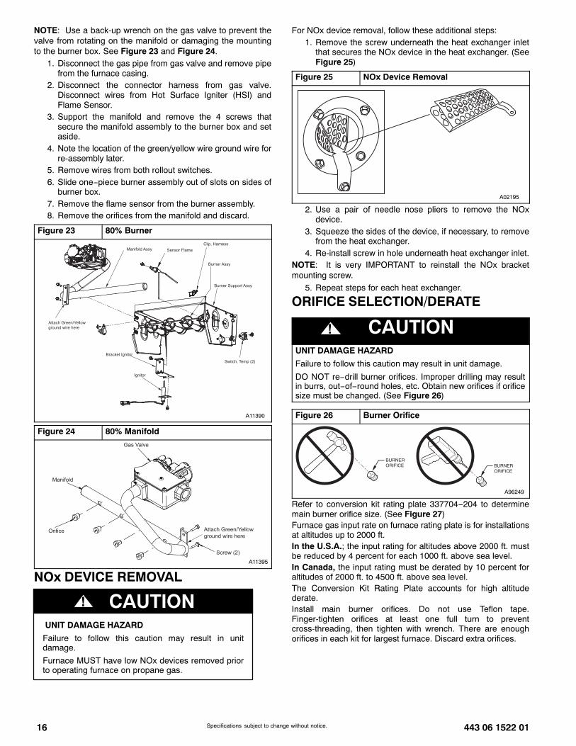
For NOx device removal, follow these additional steps:1. Remove the screw underneath the heat exchanger inlet
that secures the NOx device in the heat exchanger. (SeeFigure 25)
Figure 25 NOx Device Removal
A02195
2. Use a pair of needle nose pliers to remove the NOxdevice.
3. Squeeze the sides of the device, if necessary, to removefrom the heat exchanger.
4. Re-install screw in hole underneath heat exchanger inlet.NOTE: It is very IMPORTANT to reinstall the NOx bracketmounting screw.
5. Repeat steps for each heat exchanger.
ORIFICE SELECTION/DERATE
! CAUTIONUNIT DAMAGE HAZARD
Failure to follow this caution may result in unit damage.
DO NOT re−drill burner orifices. Improper drilling may resultin burrs, out−of−round holes, etc. Obtain new orifices if orificesize must be changed. (See Figure 26)
Figure 26 Burner Orifice
BURNER ORIFICE BURNER
ORIFICE
A96249
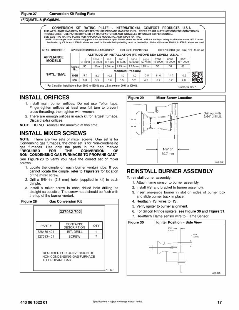
Refer to conversion kit rating plate 337704−204 to determinemain burner orifice size. (See Figure 27)Furnace gas input rate on furnace rating plate is for installationsat altitudes up to 2000 ft.In the U.S.A.; the input rating for altitudes above 2000 ft. mustbe reduced by 4 percent for each 1000 ft. above sea level.In Canada, the input rating must be derated by 10 percent foraltitudes of 2000 ft. to 4500 ft. above sea level.The Conversion Kit Rating Plate accounts for high altitudederate.Install main burner orifices. Do not use Teflon tape.Finger-tighten orifices at least one full turn to preventcross-threading, then tighten with wrench. There are enoughorifices in each kit for largest furnace. Discard extra orifices.
443 06 1522 01 17Specifications subject to change without notice.
Figure 27 Conversion Kit Rating Plate
(F/G)8MTL & (F/G)8MVL
INSTALL ORIFICES1. Install main burner orifices. Do not use Teflon tape.
Finger-tighten orifices at least one full turn to preventcross-threading, then tighten with wrench.
2. There are enough orifices in each kit for largest furnace.Discard extra orifices.
NOTE: DO NOT reinstall the manifold at this time.
INSTALL MIXER SCREWSNOTE: There are two sets of mixer screws. One set is forCondensing gas furnaces, the other set is for Non-condensinggas furnaces. Use only the parts in the bag marked“REQUIRED FOR THE CONVERSION OFNON−CONDENSING GAS FURNACES TO PROPANE GAS”See Figure 28 to verify you have the correct set of mixerscrews.
1. Locate the dimple on each burner venturi tube. If youcannot locate the dimple, refer to Figure 29 for locationof the mixer screw.
2. Drill a 5/64-in. (2.8 mm) hole (supplied in kit) in eachdimple.
3. Install a mixer screw in each drilled hole drilling asstraight as possible. The screw head should be flush withthe top of the burner venturi.
Figure 28 Gas Conversion Kit
A11397
Figure 29 Mixer Screw Location
A06432
REINSTALL BURNER ASSEMBLYTo reinstall burner assembly:
1. Attach flame sensor to burner assembly.2. Install HSI and bracket to burner assembly.3. Insert one-piece burner in slot on sides of burner box
and slide burner back in place.4. Reattach HSI wires to HSI.5. Verify igniter to burner alignment.6. For Silicon Nitride igniters, see Figure 30 and Figure 31.7. Re-attach Flame sensor wire to Flame Sensor.
Figure 30 Igniter Position − Side View9/32”7.1mm
5/16”7.9mm
A05025
18 443 06 1522 01Specifications subject to change without notice.
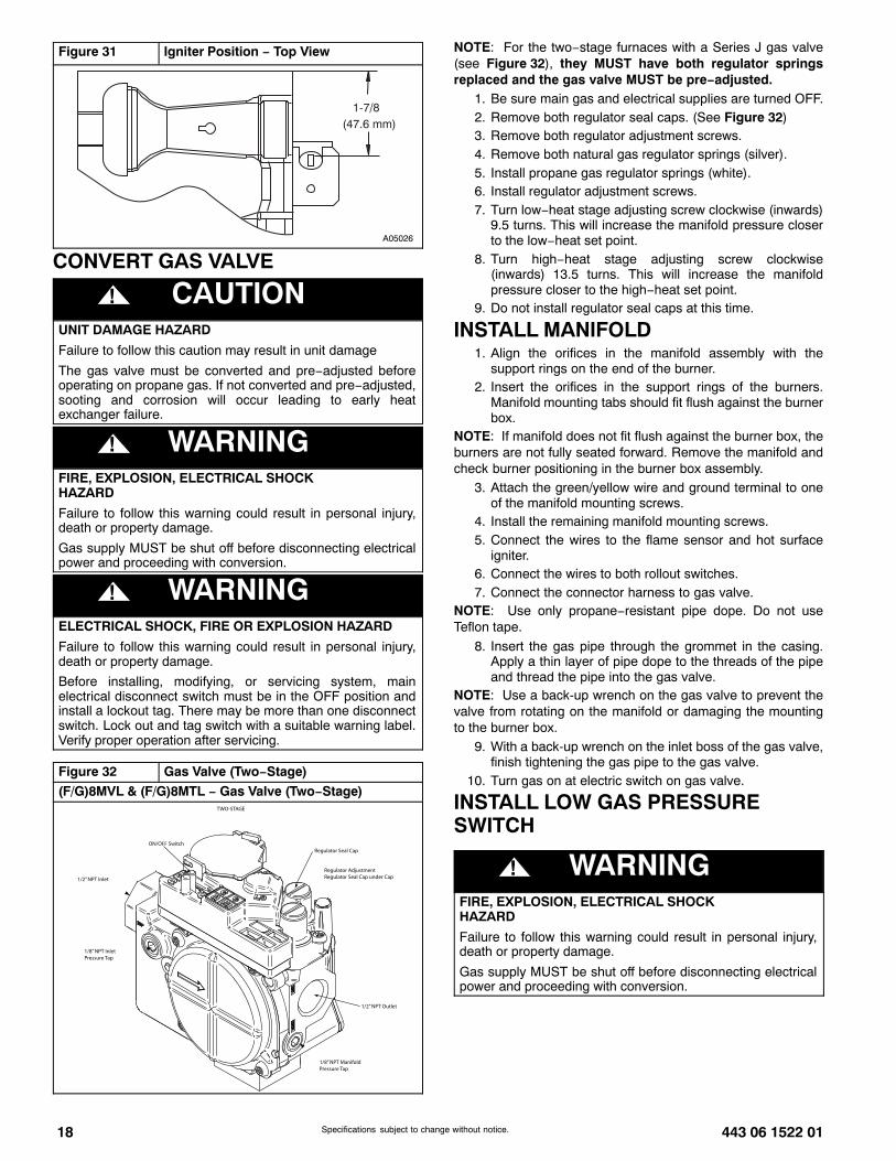
Figure 31 Igniter Position − Top View
1-7/8(47.6 mm)
A05026
CONVERT GAS VALVE
! CAUTIONUNIT DAMAGE HAZARD
Failure to follow this caution may result in unit damage
The gas valve must be converted and pre−adjusted beforeoperating on propane gas. If not converted and pre−adjusted,sooting and corrosion will occur leading to early heatexchanger failure.
! WARNINGFIRE, EXPLOSION, ELECTRICAL SHOCKHAZARD
Failure to follow this warning could result in personal injury,death or property damage.
Gas supply MUST be shut off before disconnecting electricalpower and proceeding with conversion.
! WARNINGELECTRICAL SHOCK, FIRE OR EXPLOSION HAZARD
Failure to follow this warning could result in personal injury,death or property damage.
Before installing, modifying, or servicing system, mainelectrical disconnect switch must be in the OFF position andinstall a lockout tag. There may be more than one disconnectswitch. Lock out and tag switch with a suitable warning label.Verify proper operation after servicing.
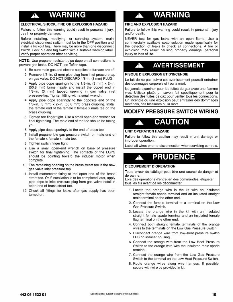
Figure 32 Gas Valve (Two−Stage)
(F/G)8MVL & (F/G)8MTL − Gas Valve (Two−Stage)
ON/OFF SwitchRegulator Seal Cap
Regulator AdjustmentRegulator Seal Cap under Cap
1/2” NPT Outlet
1/8” NPT ManifoldPressure Tap
1/8” NPT InletPressure Tap
1/2” NPT Inlet
TWO-STAGE
NOTE: For the two−stage furnaces with a Series J gas valve(see Figure 32), they MUST have both regulator springsreplaced and the gas valve MUST be pre−adjusted.
1. Be sure main gas and electrical supplies are turned OFF.2. Remove both regulator seal caps. (See Figure 32)3. Remove both regulator adjustment screws.4. Remove both natural gas regulator springs (silver).5. Install propane gas regulator springs (white).6. Install regulator adjustment screws.7. Turn low−heat stage adjusting screw clockwise (inwards)
9.5 turns. This will increase the manifold pressure closerto the low−heat set point.
8. Turn high−heat stage adjusting screw clockwise(inwards) 13.5 turns. This will increase the manifoldpressure closer to the high−heat set point.
9. Do not install regulator seal caps at this time.
INSTALL MANIFOLD1. Align the orifices in the manifold assembly with the
support rings on the end of the burner.2. Insert the orifices in the support rings of the burners.
Manifold mounting tabs should fit flush against the burnerbox.
NOTE: If manifold does not fit flush against the burner box, theburners are not fully seated forward. Remove the manifold andcheck burner positioning in the burner box assembly.
3. Attach the green/yellow wire and ground terminal to oneof the manifold mounting screws.
4. Install the remaining manifold mounting screws.5. Connect the wires to the flame sensor and hot surface
igniter.6. Connect the wires to both rollout switches.7. Connect the connector harness to gas valve.
NOTE: Use only propane−resistant pipe dope. Do not useTeflon tape.
8. Insert the gas pipe through the grommet in the casing.Apply a thin layer of pipe dope to the threads of the pipeand thread the pipe into the gas valve.
NOTE: Use a back-up wrench on the gas valve to prevent thevalve from rotating on the manifold or damaging the mountingto the burner box.
9. With a back-up wrench on the inlet boss of the gas valve,finish tightening the gas pipe to the gas valve.
10. Turn gas on at electric switch on gas valve.
INSTALL LOW GAS PRESSURESWITCH
! WARNINGFIRE, EXPLOSION, ELECTRICAL SHOCKHAZARD
Failure to follow this warning could result in personal injury,death or property damage.
Gas supply MUST be shut off before disconnecting electricalpower and proceeding with conversion.
443 06 1522 01 19Specifications subject to change without notice.
! WARNINGELECTRICAL SHOCK, FIRE OR EXPLOSION HAZARD
Failure to follow this warning could result in personal injury,death or property damage.
Before installing, modifying, or servicing system, mainelectrical disconnect switch must be in the OFF position andinstall a lockout tag. There may be more than one disconnectswitch. Lock out and tag switch with a suitable warning label.Verify proper operation after servicing.
NOTE: Use propane−resistant pipe dope on all connections toprevent gas leaks. DO NOT use Teflon tape.
1. Be sure main gas and electric supplies to furnace are off.2. Remove 1/8−in. (3 mm) pipe plug from inlet pressure tap
on gas valve. DO NOT DISCARD 1/8-in. (3 mm) PLUG.3. Apply pipe dope sparingly to the 1/8−in. (3 mm) x 2−in.
(50.8 mm) brass nipple and install the doped end in1/8−in. (3 mm) tapped opening in gas valve inletpressure-tap. Tighten fitting with a small wrench.
4. Apply pipe dope sparingly to the opposite end of the1/8−in. (3 mm) x 2−in. (50.8 mm) brass coupling. Installthe female end of the female x female x male tee on thebrass coupling.
5. Tighten tee finger tight. Use a small open-end wrench forfinal tightening. The male end of the tee should be facingyou.
6. Apply pipe dope sparingly to the end of brass tee.7. Install propane low gas pressure switch on male end of
the female x female x male tee.8. Tighten switch finger tight.9. Use a small open-end wrench on base of pressure
switch for final tightening. The contacts of the LGPSshould be pointing toward the inducer motor whencomplete.
10. The remaining opening on the brass street tee is the newgas valve inlet pressure tap
11. Install manometer fitting to the open end of the brassstreet tee. Or if installation is to be completed later, applypipe dope to inlet pressure plug from gas valve install inopen end of brass street tee.
12. Check all fittings for leaks after gas supply has beenturned on.
! WARNINGFIRE AND EXPLOSION HAZARD
Failure to follow this warning could result in personal injuryand/or death.
NEVER test for gas leaks with an open flame. Use acommercially available soap solution made specifically forthe detection of leaks to check all connections. A fire orexplosion may result causing property damage, personalinjury or loss of life.
! AVERTISSEMENTRISQUE D’EXPLOSION ET D’INCENDIE
Le fait de ne pas suivre cet avertissement pourrait entraînerdes dommages corporels et / ou la mort.
Ne jamais examiner pour les fuites de gaz avec une flammevive. Utilisez plutôt un savon fait specifiquement pour ladétection des fuites de gaz pour verifier tous les connections.Un incendie ou une explosion peut entrainer des dommagesmatériels, des blessures ou la mort.
MODIFY PRESSURE SWITCH WIRING
! CAUTIONUNIT OPERATION HAZARD
Failure to follow this caution may result in unit damage orimproper operation.
Label all wires prior to disconnection when servicing controls.
! PRUDENCED’EQUIPEMENT D’OPERATION
Toute erreur de câblage peut être une source de danger etde panne.Lors des opérations d’entretien des commandes, étiquetertous les fils avant de les déconnecter.
1. Locate the orange wire in the kit with an insulatedstraight female spade terminal and an insulated straightmale terminal on the other end.
2. Connect the female terminal to a terminal on the LowGas Pressure Switch.
3. Locate the orange wire in the kit with an insulatedstraight female spade terminal and an insulated femaleflag terminal on the other end.
4. Connect both straight female terminals of the orangewires to the terminals on the Low Gas Pressure Switch.
5. Disconnect orange wire from low−heat pressure switchLPS on inducer housing.
6. Connect the orange wire from the Low Heat PressureSwitch to the orange wire with the insulated male spadeterminal.
7. Connect the orange wire from the Low Gas PressureSwitch to the terminal on the Low Heat Pressure Switch.
8. Route orange wires along wire harness. If possible,secure with wire tie provided in kit.
20 443 06 1522 01Specifications subject to change without notice.
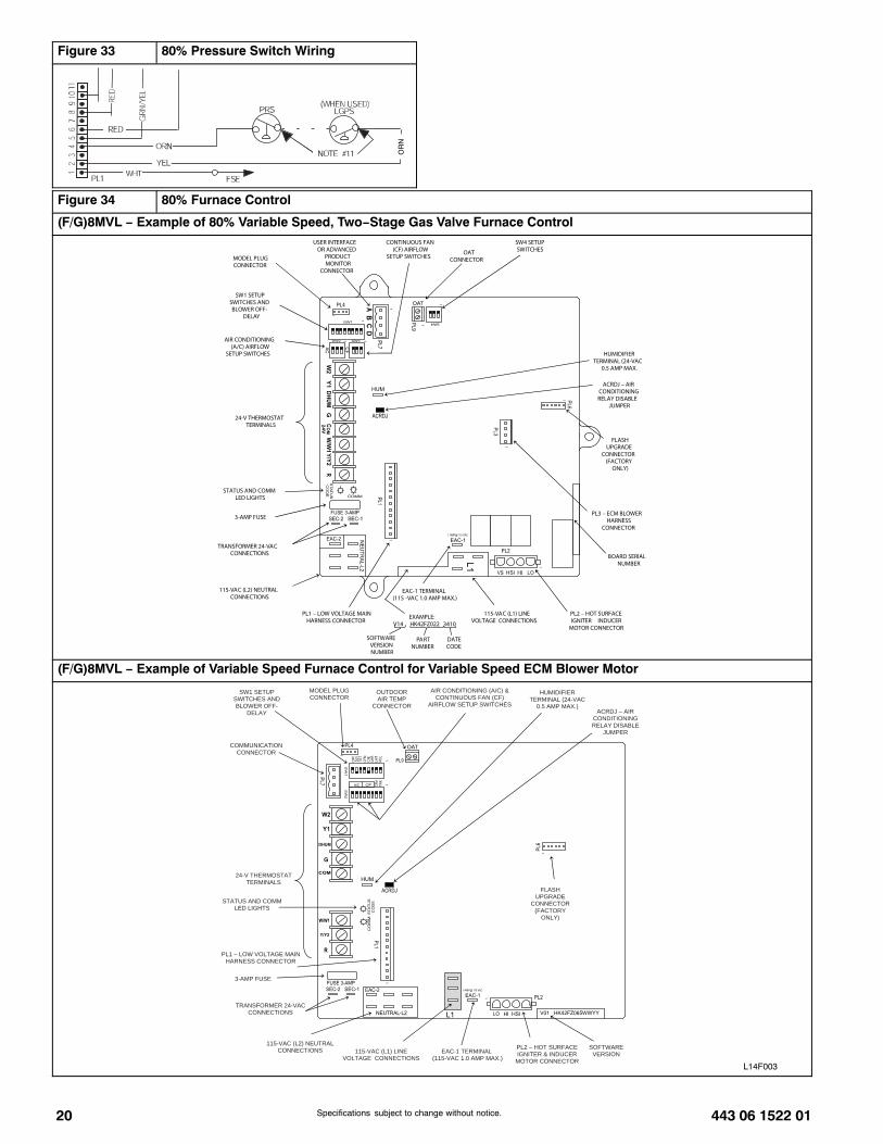
Figure 33 80% Pressure Switch Wiring
OR
N
Figure 34 80% Furnace Control
(F/G)8MVL − Example of 80% Variable Speed, Two−Stage Gas Valve Furnace Control
24-V THERMOSTAT TERMINALS
PL2 – HOT SURFACE IGNITER INDUCER
MOTOR CONNECTOR
115-VAC (L2) NEUTRAL CONNECTIONS
115-VAC (L1) LINE VOLTAGE CONNECTIONS
EAC-1 TERMINAL (115 -VAC 1.0 AMP MAX.)
PL1 – LOW VOLTAGE MAIN HARNESS CONNECTOR
PL3 – ECM BLOWER HARNESS
CONNECTOR
TRANSFORMER 24-VAC CONNECTIONS
3-AMP FUSE
STATUS AND COMM LED LIGHTS
SW1 SETUP SWITCHES AND BLOWER OFF-
DELAY
MODEL PLUG CONNECTOR
AIR CONDITIONING (A/C) AIRFLOW
SETUP SWITCHES
USER INTERFACE OR ADVANCED
PRODUCT MONITOR
CONNECTOR
CONTINUOUS FAN (CF) AIRFLOW
SETUP SWITCHES OAT
CONNECTOR
HUMIDIFIER TERMINAL (24-VAC
0.5 AMP MAX.
ACRDJ – AIR CONDITIONING RELAY DISABLE
JUMPER
FLASH UPGRADE
CONNECTOR (FACTORY
ONLY)
SW4 SETUP SWITCHES
BOARD SERIAL NUMBER
EXAMPLE: V14 HK42FZ022 3410
SOFTWARE VERSION NUMBER
DATE CODE
PART NUMBER
(F/G)8MVL − Example of Variable Speed Furnace Control for Variable Speed ECM Blower Motor
L14F003
24-V THERMOSTAT TERMINALS
PL2 – HOT SURFACE IGNITER & INDUCER
MOTOR CONNECTOR
115-VAC (L2) NEUTRAL CONNECTIONS 115-VAC (L1) LINE
VOLTAGE CONNECTIONS EAC-1 TERMINAL
(115-VAC 1.0 AMP MAX.)
PL1 – LOW VOLTAGE MAIN HARNESS CONNECTOR
TRANSFORMER 24-VAC CONNECTIONS
3-AMP FUSE
STATUS AND COMM LED LIGHTS
SW1 SETUP SWITCHES AND BLOWER OFF-
DELAY
MODEL PLUG CONNECTOR
COMMUNICATION CONNECTOR
AIR CONDITIONING (A/C) & CONTINUOUS FAN (CF)
AIRFLOW SETUP SWITCHES
OUTDOOR AIR TEMP
CONNECTOR
HUMIDIFIER TERMINAL (24-VAC
0.5 AMP MAX.) ACRDJ – AIR
CONDITIONING RELAY DISABLE
JUMPER
FLASHUPGRADE
CONNECTOR (FACTORY
ONLY)
SOFTWARE VERSION
443 06 1522 01 21Specifications subject to change without notice.
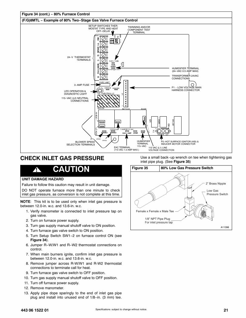
Figure 34 (cont.) − 80% Furnace Control
(F/G)8MTL − Example of 80% Two−Stage Gas Valve Furnace Control
ÎÎÎÎÎÎÎÎÎÎÎÎÎÎÎ
SETUP SWITCHES THER-MOSTAT TYPE AND HEAT
OFF−DELAY
TWINNING AND/ORCOMPONENT TEST
TERMINAL
P1 − LOW VOLTAGE MAINHARNESS CONNECTOR
TRANSFORMER 24VACCONNECTIONS
P2−HOT SURFACE IGNITOR (HSI) &INDUCER MOTOR CONNECTOR
115 VAC (L1) LINEVOLTAGE CONNECTION
EAC TERMINAL(115 VAC 1.0 AMP MAX.)
SPARE2SPARE1
COM/BLUE
115−VAC (L2) NEUTRALCONNECTIONS
24−V THERMOSTATTERMINALS
HUMIDIFIER TERMINAL(24−VAC 0.5 AMP MAX)
3−AMP FUSE
LED OPERATION &DIAGNOSTIC LIGHT
24VAC/RED
BLOWER SPEEDSELECTION TERMINALS
HUMXFMR
HUMIDIFIERTERMINAL115−VAC
HUM24VAC
TTOFFDLY
EAC 1 AMPSPARE1 SPARE2
SW
1
CHECK INLET GAS PRESSURE
! CAUTIONUNIT DAMAGE HAZARD
Failure to follow this caution may result in unit damage.
DO NOT operate furnace more than one minute to checkinlet gas pressure, as conversion is not complete at this time.
NOTE: This kit is to be used only when inlet gas pressure isbetween 12.0-in. w.c. and 13.6-in. w.c.
1. Verify manometer is connected to inlet pressure tap ongas valve.
2. Turn on furnace power supply.3. Turn gas supply manual shutoff valve to ON position.4. Turn furnace gas valve switch to ON position.5. Turn Setup Switch SW1−2 on furnace control ON (see
Figure 34).6. Jumper R−W/W1 and R−W2 thermostat connections on
control.7. When main burners ignite, confirm inlet gas pressure is
between 12.0-in. w.c. and 13.6-in. w.c.8. Remove jumper across R-W/W1 and R-W2 thermostat
connections to terminate call for heat.9. Turn furnace gas valve switch to OFF position.
10. Turn gas supply manual shutoff valve to OFF position.11. Turn off furnace power supply.12. Remove manometer.13. Apply pipe dope sparingly to the end of inlet gas pipe
plug and install into unused end of 1/8−in. (3 mm) tee.
Use a small back−up wrench on tee when tightening gasinlet pipe plug. (See Figure 35)
Figure 35 80% Low Gas Pressure Switch
2” Brass Nipple
Low Gas
Pressure Switch
Female x Female x Male Tee
1/8” NPT Pipe Plug
For inlet pressure tap
A11398

22 443 06 1522 01Specifications subject to change without notice.
CHECK FURNACE AND MAKEADJUSTMENTS
! WARNINGFIRE AND EXPLOSION HAZARD
Failure to follow this warning could result in personal injuryand/or death.
NEVER test for gas leaks with an open flame. Use acommercially available soap solution made specifically forthe detection of leaks to check all connections. A fire orexplosion may result causing property damage, personalinjury or loss of life.
! AVERTISSEMENTRISQUE D’EXPLOSION ET D’INCENDIE
Le fait de ne pas suivre cet avertissement pourrait entraînerdes dommages corporels et / ou la mort.
Ne jamais examiner pour les fuites de gaz avec une flammevive. Utilisez plutôt un savon fait specifiquement pour ladétection des fuites de gaz pour verifier tous les connections.Un incendie ou une explosion peut entrainer des dommagesmatériels, des blessures ou la mort.
! WARNINGFIRE, EXPLOSION, ELECTRICAL SHOCKHAZARD
Failure to follow this warning could result in personal injury,death or property damage.
Gas supply MUST be shut off before disconnecting electricalpower and proceeding with conversion.
! WARNINGELECTRICAL SHOCK, FIRE OR EXPLOSION HAZARD
Failure to follow this warning could result in personal injury,death or property damage.
Before installing, modifying, or servicing system, mainelectrical disconnect switch must be in the OFF position andinstall a lockout tag. There may be more than one disconnectswitch. Lock out and tag switch with a suitable warning label.Verify proper operation after servicing.
1. Be sure main gas and electric supplies to furnace are off.2. Remove 1/8−in. (3 mm) pipe plug from manifold pressure
tap on downstream side of gas valve.3. Attach manometer to manifold pressure tap on gas
valve.4. Turn gas supply manual shutoff valve to ON position.5. Turn furnace gas valve switch to ON position.6. Check all threaded pipe connections for gas leaks.7. Turn on furnace power supply.
GAS INPUT RATE INFORMATIONThe gas input rate for propane is the same as for natural gas.See furnace rating plate for input rate. The input rate forpropane is determined by manifold pressure and orifice size.The gas valve must be set for Low Heat first and then set forHigh Heat on two-stage and variable-speed furnaces. Furnacegas input rate on rating plate is for installations at altitudes up to2000 ft. (610 M).In the U.S.A., the input rating for altitudes above 2000 ft. (610M) must be reduced by 4 percent for each 1000 ft. (305 M)above sea level.
In Canada, the input rating must be derated by 10 percent foraltitudes of 2000 ft. (610 M) to 4500 ft. (1372 M) above sealevel.The Conversion Kit Rating Plate accounts for high altitudederate.
SET GAS INPUT RATE1. Verify SW1-2 on furnace control is turned “ON”. (See
Figure 34)2. Jumper R and W/W1 thermostat connections to call for
heat.3. Check manifold orifices for gas leaks when main burners
ignite.4. Adjust gas manifold pressure. (Refer to conversion kit
rating plate 339268−204 .5. Remove caps that conceal adjustment screws for gas
valve regulators. (See Figure 32)
Figure 36 Burner Flame
Burner Flame
Burner
Manifold A11461
6. Adjust low−heat manifold pressure for propane gas. (SeeFigure 32)
7. Turn low−heat adjusting screw counterclockwise (out) todecrease input rate or clockwise (in) to increase inputrate.
NOTE: When correct input is obtained, main burner flameshould be clear blue, almost transparent (see Figure 36).
8. Jumper R, W/W1 and W2 on control center thermostatconnections. This keeps furnace locked in high−heatoperation.
9. Adjust high−heat manifold pressure for propane gas.10. Turn high−heat adjusting screw counterclockwise (out) to
decrease input rate or clockwise (in) to increase inputrate.
11. Replace caps that conceal gas valve regulatoradjustment screws.
NOTE: When correct input is obtained, main burner flameshould be clear blue, almost transparent. (See Figure 36).
12. Remove jumper across R, W1, and W2 after high−heatadjustment to terminate call for heat.
13. Turn setup switch SW1-2 on furnace control to OFFposition.
14. Turn furnace gas valve switch to OFF position.15. Turn off furnace power supply.16. Remove manometer and re-install manifold pressure tap
plug.17. Turn furnace gas valve switch to ON position.18. Turn on furnace power supply.19. Set room thermostat to call for heat.20. Check pressure tap plug for gas leaks when main
burners ignite.21. Check for correct burner flame.22. Observe unit operation through two complete heating
cycles.23. See Sequence of Operation in furnace Installation,
Start−Up, and Operating Instructions.24. Set room thermostat to desired temperature.
443 06 1522 01 23Specifications subject to change without notice.
After making the required manifold pressure adjustments,check and adjust the furnace temperature rise per the furnaceinstallation instructions.
CHECK LOW GAS PRESSURESWITCHThe newly installed low gas pressure switch is a safety deviceused to guard against adverse burner operating characteristicsthat can result from low gas supply pressure. Switch opens atnot less than 6.5 in. w.c. and closes at not greater than 10.2 in.w.c.This switch also prevents operation when the propane tanklevel is low which can result in gas with a high concentration ofimpurities, additives, and residues that have settled to thebottom of the tank. Operation under these conditions cancause harm to the heat exchanger system. This normally openswitch closes when gas is supplied to gas valve under normaloperating pressure. The closed switch completes control circuit.Should an interruption or reduction in gas supply occur, the gaspressure at switch drops below low gas pressure switch setting,and switch opens. Any interruption in control circuit (in whichlow gas pressure switch is wired) quickly closes gas valve andstops gas flow to burners. When normal gas pressure isrestored, the system must be electrically reset to re−establishnormal heating operation.
Before leaving installation, observe unit operation through twocomplete heating cycles. During this time, turn gas supply togas valve off just long enough to completely extinguish burnerflame, then instantly restore full gas supply. To ensure properlow gas pressure switch operation, observe that there is no gassupply to burners until after hot surface igniter begins glowing.
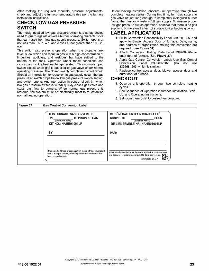
LABEL APPLICATION1. Fill in Conversion Responsibility Label 339268−205 and
apply to Blower Access Door of furnace. Date, name,and address of organization making this conversion arerequired. (See Figure 37)
2. Attach Conversion Rating Plate Label 339268−204 toouter door of furnace. (See Figure 37)
3. Apply Gas Control Conversion Label: Use Gas ControlConversion Label 339268−202. (Do not use339268−203, which is similar.)
4. Replace control access door, blower access door andouter door of furnace.
CHECKOUT1. Observe unit operation through two complete heating
cycles.2. See Sequence of Operation in furnace Installation, Start−
Up, and Operating Instructions.3. Set room thermostat to desired temperature.
Figure 37 Gas Control Conversion Label
Copyright 2017 International Comfort Products � PO Box 128 � Lewisburg, TN 37091 USA