Embed Size (px)
Citation preview

Installation instructions Gator
© Carl Wittkopp GmbH - Errors and omissions excepted
Installation instructions no 9999-134-0
Content
1 General instructions _____________________________________________________________ 2
2 System overview _________________________________________________________________ 2
3 Installation input unit Gator RO ___________________________________________________ 3
4 Installation input unit Gator FL ____________________________________________________ 6
5 Installation input unit Gator FS ____________________________________________________ 7
6 Installation input unit Gator F/DF/R/DR _____________________________________________ 8
7 Installation lock Gator 2000/3000/3010/5000/6000/8000/9000 ____________________ 12
8 Bus address ___________________________________________________________________ 15
9 External power supply ___________________________________________________________ 16
10 Wiring _______________________________________________________________________ 16
11 Functional test ________________________________________________________________ 19

2
Installation instructions Gator
Rel. 1.2
1 General instructions
• Please read the installation instructions carefully, before activating the lock.
1.1 Liability notes
• The mounting of the electronic lock and the input unit has to be carried out according to the installation instruction.• We point out that this installation instruction is part of the VdS-certification and non-compliance leads to the loss of this
certification.• By opening the lock cover warranty of the manufacturer will be void.• Take care that the input unit or the lock and the cables should not be damaged.
2 System overview
GATOR F GATOR DF GATOR R GATOR DR GATOR RO GATOR FL GATOR FS
GATOR 2000 • • •
GATOR 3000 3010 • • •* • •
GATOR 5000 • • •** •**
6000GATOR 8000 9000
• •
* can serve simultaneously as boltwork actuator ** without redundancy

3
Installation instructions Gator
Rel. 1.2
3 Installation input unit Gator RO
3.1 Input unit Gator RO 3.1.1 Dimensions Gator RO
3.2 Installation overview3.2.1 Input unit Gator RO
Fixing ring for input unit
Cylinder screws M4 x 10
Connection axis forturnable input unit
Input unit
Connection cable
3.3 Panel hole Gator RO (turnable)
3.3.1 Spindle square 3.3.2 Spindle round
Türlochbohrung
Türlochbohrung mind. ø9 - max. ø10,6
mind . ø10,6 - max. ø11,4min. Ø 10,6 mm/max. Ø 11,4 mm
Türlochbohrung
Türlochbohrung mind. ø9 - max. ø10,6
mind . ø10,6 - max. ø11,4
min. Ø 9 mm/max. Ø 11,4 mm

4
Installation instructions Gator
Rel. 1.2
3.4 Axis length calculation input unit Gator RO (turnable)
3.4.1 In connection with Gator 2000 3.4.2 In connection with boltwork
Connection axis:Debur the ends
L = A + 43mm (Toleranz - 4mm)
AL
L = A + 43mm (Toleranz - 4mm)
AL
L = A + 43mm (Toleranz - 4mm)
AL
L = 15mm + A + X
A 15X
Achse in axialer Richtung gegen verschieben sichern
L
L = 15mm + A + X
A 15X
Achse in axialer Richtung gegen verschieben sichern
L
Secure the axis against shifting in axial direction.
Connection axis:Debur the ends
L = A + 43 mm (tolerance -4 mm) L = X + A + 15 mm (+ axial hedge)
3.5 Mounting
3.5.1 Drill pattern fixing ring Gator RO
4 x Fixing position for M4
Gator RO (fixed) - opening for cable:Drill-hole min. Ø 8 mm/max. Ø 11,4 mm for connection cable
Gator RO (turnable):Hole center congruent with middle axis of nut of the electronic lock.Drill-hole min. Ø 9 mm/max. Ø 11,4 mm for connection axis (see p. 3, fig. 3.2).
7878
4,3
4
3
3
4
4,3
• From the front 4 threaded holes M4 with sufficient depth thread and 1 through-hole (opening for cable/connection axis) have to be drilled into the safe door.
• From the front the fixing ring has to be fixed with the enclosed cylinder screws M4 x 10.
3.5.2 Mounting input unit Gator RO
Position 1
20°
Position 2
• Position 1: Mount the input unit with an angle of approx. 20° to the fixing ring.• Position 2: Turn the input unit to the right into position. The turning has to happen easily.

5
Installation instructions Gator
Rel. 1.2
3.5.3 Input unit Gator RO (fixed)
3
20
Drill-hole Ø 3,4 mm in the safe door to fix the input unit
• Fit input unit of approx. 20° (see 3.4.2), adjusting to the locked lock/boltwork and insert grub screw M3 x 6 or arrest pin.
3.5.4 Cable guidance Gator RO (turnable) 3.5.5 Plug position Gator RO
Connection axis
Audit
Lock/Gator PowerAdapt
• Gator RO (turnable): Lead connection cable through the input unit.• Gator RO (turnable): Insert the connection axis into the input unit from behind.• Gator RO (turnable/fixed): Lead connection cable through the input unit and connect the plug.

6
Installation instructions Gator
Rel. 1.2
4.2.2 Battery compartment 4.2.3 Plug position Gator FL
Battery
Audit
Lock/Gator PowerAdapt
• The battery compartment has to be fixed to the inside of the door. It is recommended to fix it in a way that it is accessible without unscrewing the interior of the door.
• Drill pattern see chapter 9.1.2• To avoid a short circuit/independent discharge, no
connection between the inputs of the battery compart-ment and other components may occur.
• The two 4-pin plug connection must be accessible at all times.
• Attention: Fot the comfortable reading out the audit,the connection cable audit has to be connect at the input unit durable and has to be lead well accessible.
4 Installation input unit Gator FL
4.1 Input unit Gator FL(fixing on the inside)
4.1.2 Input unit Gator FL(fixing on the front)
4.1.3 Dimensions Gator FL
Emergency power supply
4.2 Mounting
4.2.1 Drill pattern Gator FL
Fixing position:- Fixing on the inside: Through-hole for screws M5- Fixing on the front: Thread M3
Ø 92
Notbestromung/emergency power supply
12
82
Opening for cable:Drill-hole min. Ø 8 mm/max. Ø 11,4 mm in the safe door for connection cable
• Fixing on the inside: 2 through-holes for screws M5 and 1 through-hole (opening for cable) have to be drilled into the safe door. Fix the input unit with 2 screws M5 from behind.• Fixing on the front: From the front 2 threaded holes M3 with sufficient depth and 1 through-hole (opening for cable) have to be drilled into the safe door. Fix the input unit with 2 screws M5 from the front.

7
Installation instructions Gator
Rel. 1.2
5 Installation input unit Gator FS
5.1 Input unit Gator FS 5.1.1 Dimensions Gator FS
Ø 95 40 46
23
5,1
5
5.2 Mounting
5.2.1 Drill pattern Gator FS
Fixing position for screws M5
Ø 95 40 46
23
5,1
5
Opening for cable:Drill-hole min. Ø 8 mm/max. Ø 11,4 mm for connection cable has to be drilled into the safe door
• From the front 2 threaded holes M5 with sufficient depth and 1 through-hole (opening for cable) have to be drilled into the safe door.
• Fix the input unit with the enclosed cylinder screws M5 from the front.
5.2.2 Cable routing Gator FS 5.2.3 Plug position Gator FS
Bottom of case
Connection cable lock
Battery clip
Folding unit
Fixing screwBattery
Audit
Lock/Gator PowerAdapt
• Lead connection cable lock and connection cable battery behind the bottom of casse of the input unit..

8
Installation instructions Gator
Rel. 1.2
6 Installation input unit Gator F/DF/R/DR
6.1 Input unit Gator F/DF 6.1.1 Input unit Gator R/DR
iButton-reader(optional)
iButton-reader(optional)
6.1.2 Dimensions Gator F/DF 6.1.3 Dimensions Gator R/DR
14
Kabeldurchlass/Opening for cable
6.2 Axis length calculation input unit Gator R/DR
6.2.1 In Verbindung mit Gator 2000
A
L = A + 43mm (Toleranz - 4mm)
AL
Connection axis:Debur the ends
L = A + 48 mm (tolerance -1,5 mm)

9
Installation instructions Gator
Rel. 1.2
6.3 Mounting
6.3.1 Drill pattern Gator F/DF/R/DR
Gator F/DF: Opening for cable: Drill-hole min. Ø 8 mm/max. Ø 11,4 mm for connection cableGator R/DR: Hole center congruent with middle axis of nut of the electronic lock. Drill-hole min. Ø 9 mm/max. Ø 11,4 mm for connection axis (see p. 3, Fig. 3.2).
14 Fixing position for screws M4
Fixing position for screws M4
• From the front 4 threaded holes M4 with sufficient depth and 1 through-hole (opening for cable/connection axis) have to be drilled into the safe door.
• Fix the input unit with the enclosed 4 screws M4 x 12 from the front.
6.3.2 Cable routing Gator F/DF
• Lead connection cable through the connection axis and input unit.
6.3.3 Cable routing Gator R/DR
AchsadapterConnection axis
• Lead conncection cable through the spindle adaptor.• Lead conncection cable through the connection axis.• Insert the connection axis into the input unit from behind.• Connect the plug into the input unit.

10
Installation instructions Gator
Rel. 1.2
6.3.4 Plug position Gator F/DF/R/DR
Cable duc B to lockCable duct A to lock
Audit
• Cable duc A: Standard connection to the lock.• Cable duc B: Additional connection to the lock for generating a redundancy - activate configuration in Software GatorSelect
and transmit via ibutton.• Specific setting between the bus channels: The bus channel A and bus channel B of he input units can change in the foll-
wing way. ** ** ( = Arrow left) select bus channel A** ** ( = Arrow right) select bus channel B
6.3.5 Battery compartment/cover cap
1
Gator F/DF
3
Gator R/DR
42
• Fig. 1: Slide the battery compartment into the input unit from above.• Fig. 2: Fix the safety screw M4 x 16 from the side – optional.• Fig. 3: Gator F/DF: Insert cover cap at the bottom of the input unit.• Fig. 4: Gator R/DR: Insert turning knob and cover cap at the bottom of the input unit.

11
Installation instructions Gator
Rel. 1.2
6.4 Power supply display
DIP switch
6.4.1 Power supply via batteries 6.4.2 Power supply via adapter
Factory mode
• Slide DIP switch at the back of the battery compartment into illustrated position.
• Insert 3 x 1,5 AA Alkaline batteries.
• Slide DIP switch at the back of the battery compartment into illustrated position.
Attention:By energization via adapter it is recommended to remove the batteries.
12
Installation instructions Gator
Rel. 1.2
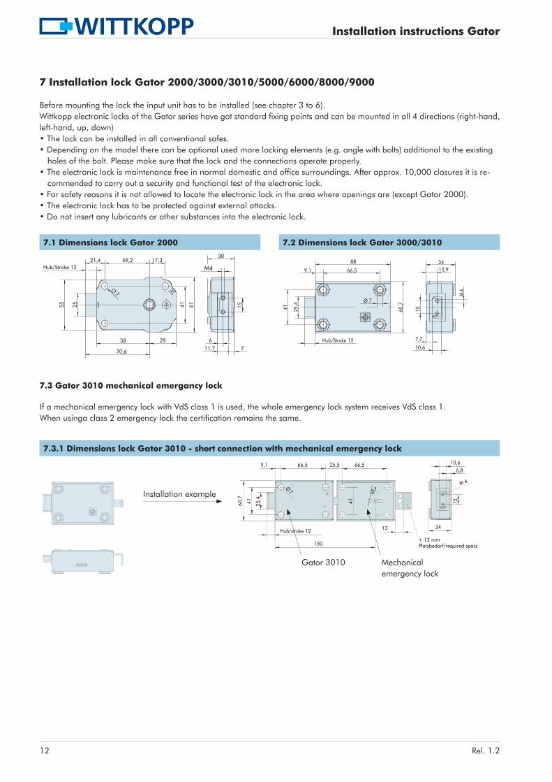
7 Installation lock Gator 2000/3000/3010/5000/6000/8000/9000
Before mounting the lock the input unit has to be installed (see chapter 3 to 6).Wittkopp electronic locks of the Gator series have got standard fixing points and can be mounted in all 4 directions (right-hand, left-hand, up, down)• The lock can be installed in all conventional safes.• Depending on the model there can be optional used more locking elements (e.g. angle with bolts) additional to the existing
holes of the bolt. Please make sure that the lock and the connections operate properly.• The electronic lock is maintenance free in normal domestic and office surroundings. After approx. 10,000 closures it is re-
commended to carry out a security and functional test of the electronic lock.• For safety reasons it is not allowed to locate the electronic lock in the area where openings are (except Gator 2000).• The electronic lock has to be protected against external attacks.• Do not insert any lubricants or other substances into the electronic lock.
7.1 Dimensions lock Gator 2000 7.2 Dimensions lock Gator 3000/3010
Hub/Stroke 12 M4
Hub/Stroke 12
9,1 66,5
88
25,4
41
Ø 7
60,7
34
10,6
15
M4
7,7
12,9
7.3 Gator 3010 mechanical emergancy lock
If a mechanical emergency lock with VdS class 1 is used, the whole emergency lock system receives VdS class 1.When usinga class 2 emergency lock the certification remains the same.
7.3.1 Dimensions lock Gator 3010 - short connection with mechanical emergency lock
60,7
+ 12 mm Platzbedarf/required space
66,59,1
41 25,4
Ø7
Hub/stroke 12
25,5 66,5
13
Ø7
150
41
6,8
34
15
M 4
10,6
Mechanicalemergency lock
Gator 3010
Installation example

13
Installation instructions Gator
Rel. 1.2
7.3.2 Dimensions lock Gator 3010 - long connection with mechanical emergency lock
Installation example
Area around theunlocking lever mustbe protectedespecially.
Gator 30109,1 66,5
88116
25,44160
,7
(X)
66,588
Ø 7
Ø7
Hub/stroke 12
13,5
58,3
4160,7
3
34
25Mechanicalemergency lock
7.4 Dimensions lock Gator 5000/6000/8000/9000 7.4.1 Bolt stroke
Hub von 9 - 15 mm verstellbar/Stroke adjustable from 9 - 15 mm
66,588,5
103,4
4160,7
Ø 6,57,8
14,2
7 12
4
34
15
M4
25,4
35,7
Attention: Bolt stroke only has to be adjust when lock bolt is completely moved into lo- cking position.
Adjustment screw forbolt stroke:Stroke length can be redu-ced by turning clockwise.
• Gator 5000/6000/8000/9000: Stroke length can be be adjusted continuously from 9 – 15 mm (factory mode: 15 mm).
7.5 Mounting
7.5.1 Drill pattern Gator 2000/3000/3010/5000/6000/8000/9000
17,3
41
66,5
Gator 2000: Middle axis of nut of the electronic lock congruent withmiddle of the input unit (Gator RO)/knob input unit (Gator R/DR)
Gator 2000: drill-hole not necessary
• For fixing the electronic lock 4 threaded holes M6 with depth min. 6 mm (or a comparable inch thread) have to be drilled into the safe door.
• Gator 2000: Lead connection cable through the lock and adjust the electronic lock on the connection axis.• Fixing the lock with screws M6 or a comparable inch thread. Length and material application of the screw has to be selected
such as a secure long-term stability is guaranteed. • Turn the screws with a maximum turning force of 3.5 – 5 Nm.• Independent loosening of the screws has to be avoided. Recommendation: put lock washers underneath the screw’s head.• After the installation the lock’s bolt may not be loaded.• Mind sufficient slackness of the locking point.

14
Installation instructions Gator
Rel. 1.2
7.5.2 Bolt load Gator 2000/3000/3010/5000/6000/8000/900017,3
41
66,5
F
• The maximum and constantly bolt load against Ausschlussrichtung?????? may not exceed the following limits:Gator 2000 2,5NGator 3000 2,5NGator 5000, 6000, 8000, 9000 30 N
7.6 Plug positions7.6.1 Gator 2000 7.6.2 Gator 3000/3010
Input unit/ Gator PowerAdapt (4-pin)
GatorSignal plus (8-pin)
nput unit/Gator PowerAdapt (4-pin)
GatorSignal plus (8-pin)
7.6.3 Gator 5000 7.6.4 Gator 6000/8000/9000
GatorSignal plus (8-pin)
Input unit (4-pin)/Gator PowerAdapt
GatorSignal plus (8-pin)
Redundanz (4-pin)
nput unit/Gator PowerAdapt (4-pin)
• Plug in the connection cable of the input unit in position „Input unit“ of the lock. To remove carefully pull out the plug.• Keep away connection cable of sharp edges and movable parts of the boltwork and fix it securely.• Plug in connection cable of the signalbox (optional) in position „GatorSignal plus“ of the lock. Further installation instructions
see separate installation instruction GatorSignal plus.• Gator 6000/8000/9000: Plug in a connection cable for the redundancy between the left and the right electronic
(Plug position B - B).

15
Installation instructions Gator
Rel. 1.2
8.2 Adjusting bus addresses lock
8.2.1 Gator 2000
• Bus address fix setted on 09.
8.2.2 Gator 3000/3010/5000
Position Coding switch 0 1 2 … 9 A B C D E F
Bus address lock 00 01 02 … 09 10 11 12 13 14
8.2.3 Gator 6000/8000/9000
• Maximum 3 redundancy locks per system are available.• Pairing of the address of the redundancy locks is mandatory according to table.• The monitoring of the redundancy is only available with redundant laid bus cables and the input units Gator F/DF/R/DR .• The monitoring of the redundancy is not active - activate configuration in Software GatorSelect and transmit via ibutton.
Lock 1 Lock 2 Lock 3
Position Coding switch 0 A 1 B 2 C
Bus address lock 00 01 02
8.3 Adjusting bus addresses input units Gator RO/FL/FS/F/DF/R/DR
• The input unit must be in full working order.• The bus addresses of the input unit Bus address are factory-adjusted on 00.• The address for the the input unit has to be unique in one system.• Use the following key combination at the input unit: ***Address input unit ***
The address may have the value up 00, 01, 02 to 15 e. g. *** 02 ***
Bus address input unit 00 01 02 … 09 10 11 12 13 14 15
8 Bus address
• Within one system a maximum of 16 input units and a maximun of 15 locks can be connected.• The address for the lock and the input unit has to be unique in one system.• Gator 3000/3010/5000/6000/8000/9000: The bus addresses can be adjusted by turning the coding switch.• Gator 6000/8000/9000: For redundancy you have to adjust 2 bus addresses for 1 lock.
8.1 Coding switch Gator 3000/3010/5000/6000/8000/9000
Coding switch

16
Installation instructions Gator
Rel. 1.2
9 External power supply
• The Gator-System can externaly power supplied by Gator PowerAdapt or GatorSignal plus. • Refer to the corresponding note 6.4 Power supply display for the input units Gator DF/DR.• By energization via adapter it is recommended to remove the batteries.• Emergency power supply (optional): insert 1 x 9V block Alkaline.
9.1 Gator PowerAdapt
9.1.1 Plug position PowerAdapt 9.1.2 Drill pattern Gator PowerAdapt
Connection cable
Adapter 9V
78
41
36 47,5
• Gator PowerAdapt can be fixed with the factory-mounted double-sided adhesive tape.
9.2 GatorSignal plus
• Further Installation instructions and circuit diagram see separate installation instruction GatorSignal plus.
10 Wiring
10.1 Gator 2000 - Example circuit diagram
PowerAdapt
A
B
oder
oder
2
1
B
A
4-polig 8-polig 4-polig 8-polig4-pin 8-pin 4-pin 8-pin

17
Installation instructions Gator
Rel. 1.2
10.2 Gator 3000/3010/5000 - Example circuit diagram
PowerAdapt
PowerAdapt
optional bus cables for redundancy
Attention:• When there are more than 3 locks per system, we recommend to use further more external power supplies.
This would need to be verified individually.• Redundancy systems are only available with the input units Gator F/DF/R/DR.

18
Installation instructions Gator
Rel. 1.2
10.3 Gator 6000/8000/9000 - Beispiel Anschaltschema
A
B
B
A
B
PowerAdapt
A
A
PowerAdapt
B
B
A
A
B
B
A
A
B
B
A
A
B
optional bus cables for redundancy
Attention:• When there are more than 3 locks per system, we recommend to use further more external power supplies.
This would need to be verified individually.• Redundancy systems are only available with the input units Gator F/DF/R/DR.• Plug in a connection cable for the redundancy between the left and the right electronic (Plug position B - B).

19
Installation instructions Gator
Rel. 1.2
11 Functional test (when the door is open)
Attention: for Gator 5000/6000/8000/9000 danger of collisions! - see below• Connect the power supply: connect the battery 9V block with the battery clip in the input unit or switch on the external power
supply.• Enter the factory code:
Locks Gator 2000/3000/3010/5000/6000: 0 – 0 – 1 – 2 – 3 – 4 – 5 – 6Locks Gator 8000/9000: 0 – 0 – 1 – 2 – 3 – 4 – 5 – 6 – 0 – 0Re-enter the factory code when the power was switched off.
• Gator 2000: Turn the input unit or the knob within 20 seconds into opening position. The lock is opened.Turn the handle into opening position.Closing shall be performed in reverse order.
• Gator 3000/3010:The lock’s bolt opens automatically (has to happen easily). The lock is opened.Turn the handle within 20 seconds into opening position.Turn the handle into locking position. The lock’s bolt closes automatically and blocks. The lock is closed.
• Gator 5000/6000/8000/9000:Attention - Danger of collisions! The locks are factory setted to close automatically after 20 seconds.To avoid a collision a boltwork position switch has to be connected with GatorSignal plus.Further Installation instructions and circuit diagram see separate installation instruction GatorSignal plus.The lock’s bolt opens automatically (has to happen easily). The lock is opened. Turn the handle within 20 seconds into opening position.Turn the handle into closing position. The lock’s bolt closes automatically and blocks. The lock is closed.

20
Installation instructions Gator
Rel. 1.2