Embed Size (px)
Citation preview

92-24161-31-07SUPERSEDES 92-24161-31-06
INSTALLATION INSTRUCTIONSFOR UPFLOW, UPFLOW/HORIZONTAL, AND DOWNFLOW INDUCED DRAFT GAS FURNACES80PJ AND 80LJ SERIES
PROPOSITION 65: THIS PRODUCT CONTAINS CHEMICALS,INCLUDING CARBON MONOXIDE, KNOWN TO THE STATE OFCALIFORNIA TO CAUSE CANCER, BIRTH DEFECTS OR OTHERREPRODUCTIVE HARM.

2
Before beginning any troubleshooting procedure, complete the following installation checklist. A furnace malfunction issometimes caused by an improper installation. By completing this checklist, the problem may be found and corrected. Makecopies of the checklist and complete one for every Low Profile Furnace service call for your records.
INSTALLATION CHECKLIST(Refer to this manual for specifics.)
GAS SUPPLY
Adequate pipe size
No gas leaks
Proper supply and manifold gas pressure (check with an accurate U-tube manometer with the furnace and all other gasappliances operating.)
ELECTRICAL
Correct thermostat and subbase Thermostat model Subbase model
Correct thermostat mode and setting
Correct line supply voltage
Correct power supply polarity is required with electronic ignition
Correct furnace ground to electrical panel
DC microamp (µA) flame signal (hot surface ignition units)
Correct control voltage
Measure and set heat anticipator amperage
Air conditioning low voltage wires connected to terminals “Y” “C” - not with wire nuts
VENTING
Correct vent pipe diameter and length (according to CSA tables) Vent connection size
Correct venting material (according to CSA tables)
Correct lining for masonry chimneys
Adequate clearance from combustibles
Proper negative pressure reading in the vent
Vent pipe secured to induced draft blower housing
COMBUSTION AIR
Proper source of combustion air
Correct combustion air opening size
FURNACE INSTALLATION
Adequate clearance from combustibles
Adequate clearance for service
Proper air temperature rise (See furnace rating plate)
External static pressure inches w.c.
Correct filter(s)
Correct cooling coil or accessories (if equipped)
Adequate supply and return air ducting Return Air Duct Size Supply Air Duct Size
Air ducts sealed to prevent leakage

33
IMPORTANT: to insure proper installation and operation of this product,completely read all instructions prior to attempting to assemble, install, operate,maintain or repair this product. upon unpacking of THE furnace, inspect all partsfor damage prior to installation and start-up.
CONTENTS
Safety Precautions ...................................................................................................4
Installation Check List ..............................................................................................2
General Information..................................................................................................5
Location Requirements and Considerations ............................................................5
Combustion and Ventilation Air..............................................................................10
Vent Pipe Installation..............................................................................................13
Gas Supply and Piping...........................................................................................16
Electrical Wiring......................................................................................................20
Accessories ............................................................................................................21
Furnace Twinning...................................................................................................21
High Altitude Installations .......................................................................................24
Start-Up Procedures...............................................................................................27
Air Flow...................................................................................................................29
Safety Features ......................................................................................................32
Maintenance...........................................................................................................34
Troubleshooting......................................................................................................37
Wiring Diagrams.....................................................................................................38
IMPORTANT: All ICECO productsmeet current Federal OSHA Guidelinesfor safety. California Proposition 65warnings are required for certainproducts, which are not covered by theOSHA standards.
California's Proposition 65 requireswarnings for products sold in Californiathat contain, or produce, any of over600 listed chemicals known to the Stateof California to cause cancer or birthdefects such as fiberglass insulation,lead in brass, and combustion productsfrom natural gas.
All “new equipment” shipped for sale inCalifornia will have labels stating thatthe product contains and/or producesProposition 65 chemicals. Although wehave not changed our processes,having the same label on all ourproducts facilitates manufacturing andshipping. We cannot always know“when, or if” products will be sold in theCalifornia market.
You may receive inquiries fromcustomers about chemicals found in, orproduced by, some of our heating andair-conditioning equipment, or found innatural gas used with some of ourproducts. Listed below are thosechemicals and substances commonlyassociated with similar equipment inour industry and other manufacturers.
• Glass Wool (Fiberglass) Insulation• Carbon Monoxide (CO)• Formaldehyde• Benzene
More details are available at theWebsites for OSHA (OccupationalSafety and Health Administration), atwww.osha.gov and the State ofCalifornia's OEHHA (Office ofEnvironmental Health HazardAssessment), at www.oehha.org.Consumer education is important sincethe chemicals and substances on thelist are found in our daily lives. Mostconsumers are aware that productspresent safety and health risks, whenimproperly used, handled andmaintained.

4
NEVER TEST FOR GAS LEAKSWITH AN OPEN FLAME. USE ACOMMERCIALLY AVAILABLESOAP SOLUTION MADESPECIFICALLY FOR THEDETECTION OF LEAKS TO CHECKALL CONNECTIONS, ASSPECIFIED IN GAS SUPPLY ANDPIPING SECTION OF THESEINSTRUCTIONS.
ALWAYS INSTALL FURNACE TOOPERATE WITHIN THEFURNACE'S INTENDEDTEMPERATURE-RISE RANGEWITH A DUCT SYSTEM WHICHHAS AN EXTERNAL STATICPRESSURE WITHIN THEALLOWABLE RANGE, ASSPECIFIED IN DUCTING SECTIONOF THESE INSTRUCTIONS. SEEALSO FURNACE RATING PLATE.
WHEN A FURNACE IS INSTALLEDSO THAT SUPPLY DUCTS CARRYAIR CIRCULATED BY THEFURNACE TO AREAS OUTSIDETHE SPACE CONTAINING THEFURNACE, THE RETURN AIRSHALL ALSO BE HANDLED BYDUCT(S) SEALED TO THEFURNACE CASING ANDTERMINATING OUTSIDE THESPACE CONTAINING THEFURNACE.
WHEN THIS FURNACE ISINSTALLED IN A RESIDENTIALGARAGE, IT MUST BE INSTALLEDSO THE BURNERS AND IGNITIONSOURCE ARE LOCATED NO LESSTHAN 18 INCHES ABOVE THEFLOOR. THIS IS TO REDUCE THERISK OF IGNITING FLAMMABLEVAPORS WHICH MAYBE PRESENT IN A GARAGE.ALSO, THE FURNACE MUST BELOCATED OR PROTECTED TOAVOID PHYSICAL DAMAGE BYVEHICLES. FAILURE TO FOLLOWTHESE WARNINGS CAN CAUSE AFIRE OR EXPLOSION, RESULTINGIN PROPERTY DAMAGE,PERSONAL INJURY OR DEATH.
USE OF THIS FURNACE ISALLOWED DURINGCONSTRUCTION IF THEFOLLOWING TEMPORARYINSTALLATION REQUIREMENTSARE MET. INSTALLATION MUSTCOMPLY WITH ALLINSTALLATION INSTRUCTIONSINCLUDING:
• PROPER VENT INSTALLATION;
• FURNACE OPERATING UNDERTHERMOSTATIC CONTROL;
• RETURN AIR DUCT SEALED TOTHE FURNACE;
• AIR FILTERS IN PLACE;
• SET FURNACE INPUT RATEAND TEMPERATURE RISE PERRATING PLATE MARKING;
• MEANS FOR PROVIDINGOUTDOOR AIR REQUIRED FORCOMBUSTION;
• RETURN AIR TEMPERATUREMAINTAINED BETWEEN 55°F(13°C) AND 80°F (27°C); AND
• CLEAN FURNACE, DUCT WORKAND COMPONENTS UPONSUBSTANTIAL COMPLETION OFTHE CONSTRUCTIONPROCESS, AND VERIFYFURNACE OPERATINGCONDITIONS INCLUDINGIGNITION, INPUT RATE,TEMPERATURE RISE ANDVENTING, ACCORDING TO THEINSTRUCTIONS.
! WARNING
! WARNING
! WARNING
! WARNING
! WARNING
SAFETY INFORMATION! WARNING
! WARNING
! WARNING
! WARNING
! WARNINGDO NOT OPERATE THE SYSTEMFOR EXTENDED PERIODSWITHOUT FILTERS. A PORTIONOF THE DUST ENTRAINED IN THEAIR MAY TEMPORARILY LODGEIN THE AIR DUCT RUNS AND ATTHE SUPPLY REGISTERS. ANYCIRCULATED DUST PARTICLESWILL BE HEATED AND CHARREDBY CONTACT WITH THEFURNACE HEAT EXCHANGER.THIS SOOTY RESIDUE WILL SOILCEILINGS, WALLS, DRAPES,CARPETS AND OTHERHOUSEHOLD ARTICLES. SOOTDAMAGE MAY ALSO RESULTWITH, OR WITHOUT, FILTERS INPLACE, WHEN CERTAIN TYPESOF CANDLES ARE BURNED, ORCANDLEWICKS ARE LEFTUNTRIMMED.
COMBUSTION PRODUCTS MUSTBE DISCHARGED OUTDOORS.CONNECT THIS FURNACE TO ANAPPROVED VENT SYSTEM ONLY,AS SPECIFIED IN VENT PIPEINSTALLATION SECTION OFTHESE INSTRUCTIONS.
PROVIDE ADEQUATECOMBUSTION AND VENTILATIONAIR TO THE FURNACE SPACE ASSPECIFIED IN THE COMBUSTIONAND VENTILATION AIR SECTIONOF THESE INSTRUCTIONS.
INSTALL THIS FURNACE ONLY INA LOCATION AND POSITION ASSPECIFIED IN THE LOCATIONREQUIREMENTS ANDCONSIDERATIONS SECTION OFTHESE INSTRUCTIONS. PROVIDEADEQUATE COMBUSTION ANDVENTILATION AIR TO THEFURNACE SPACE AS SPECIFIEDIN THE VENTING SECTION OFTHESE INSTRUCTIONS.
USE ONLY WITH TYPE OF GASAPPROVED FOR THIS FURNACE.REFER TO THE FURNACE RATINGPLATE.

5
GENERAL INFORMATION
DO NOT USE THIS FURNACEDURING CONSTRUCTION IF AIRLADEN CORROSIVE COMPOUNDSARE PRESENT SUCH AS CHLORINEAND FLUORINE. OTHERWISE,PROVISIONS MUST BE TAKEN TOPROVIDE CLEAN,UNCONTAMINATED COMBUSTIONAND VENTILATION AIR TO THEFURNACE. FURNACECOMBUSTION AND VENTILATIONAIR CONTAMINATED WITH THESECOMPOUNDS FORMS ACIDSDURING COMBUSTION WHICHCORRODES THE HEATEXCHANGER AND COMPONENTPARTS. SOME OF THESECONTAMINANTS ARE FOUND IN,BUT NOT LIMITED TO, PANELING,DRY WALL, ADHESIVES, PAINTS,STAINES, VARNISHES, SEALERS,AND MASONRY CLEANINGMATERIALS.
1. NOTE: This furnace is shipped withheat exchanger support bracketsinstalled under the back of the heatexchanger. These may be removedbefore installation, but it is notrequired.
LOCATION
THIS FURNACE IS NOT APPROVEDFOR INSTALLATION IN A MOBILEHOME. DO NOT INSTALL THISFURNACE IN A MOBILE HOME.INSTALLATION IN A MOBILE HOMECOULD CAUSE FIRE, PROPERTYDAMAGE, PERSONAL INJURY ORDEATH.
2. IMPORTANT: This furnace is notapproved or recommended forinstallation on its back, with accessdoors facing upwards.
3. This furnace is suitable forinstallation in buildings constructedon-site. This heating unit should becentralized with respect to the heatdistribution system as much aspracticable.
4. NOTE: These furnaces areapproved for installation in attics, aswell as alcoves, utility rooms,closets and crawlspaces.
5. IMPORTANT: Support this unitwhen installed. For attic or crawlspace installation, horizontalfurnaces may be installed oncombustible wood flooring or byusing support brackets. See Figure1.
6. IMPORTANT: If installing in a utilityroom, be sure the door is wideenough to:
a. allow the largest part of thefurnace to pass; or
b. allow any other appliance (suchas a water heater) to pass.
The 80PJ and 80LJ series furnaces aredesign certified by CSA for use withnatural and propane gases as follows:
As a Category I furnace, it may bevented vertically with type B-1 ventpipe and also may be commonvented as described in theseinstructions.
This furnace should be installed inaccordance with the American NationalStandard Z223.1 - latest edition bookletentitled “National Fuel Gas Code”(NFPA 54) (in Canada, CSA B149.1
and .2 Installation Codes for gasburning appliances), and therequirements or codes of the local utilityor other authority having jurisdictionincluding local plumbing or waste watercodes.
Additional helpful publications availablefrom the “National Fire ProtectionAssociation” are: NFPA-90A –Installation of Air Conditioning andVentilating Systems 1985 or latestedition. NFPA-90B – Warm Air Heatingand Air Conditioning Systems 1984.
These publications are available from:
National Fire Protection Association,Inc.
Batterymarch ParkQuincy, MA 02269
CSA-INTERNATIONAL178 Rexdale Blvd.Etobicoke (Toronto), OntarioCanada M9W, 1R3
GENERAL INFORMATION
LOCATION REQUIREMENTS AND CONSIDERATIONS
WARNING!
FIGURE 1HORIZONTAL FURNACE INSTALLED W/SUPPORT BRACKETS
EXHAUSTVENT
GASPIPE
ELECTRICALCONDUIT
ST-A0799-01
CAUTION!

6
REDU
CED
CLEA
RANC
E (IN
.)
Mod
elA
BC
DE
Left
Righ
tBa
ckTo
pFr
ont
Vent
Ship
.Si
deSi
deW
gts.
0514
1227/32
103 /8
➀11
1 /20
4➁0
13
6➂85
lbs.
0717
1 /216
11/32
121 /8
➀15
03➁
01
36➂
105
lbs.
10(A
)17
1 /216
11/32
121 /8
➀15
03➁
01
36➂
115
lbs.
10(B
)21
1927/32
137 /8
➀18
1 /20
00
13
6➂12
0 lb
s.
1224
1 /223
11/32
155 /8
➀22
00
01
36➂
140
lbs.
1524
1 /223
11/32
155 /8
➀22
00
01
36➂
150
lbs.
CLE
AR
AN
CE
TO
CO
MB
US
TIB
LE M
AT
ER
IAL
(INC
HE
S)
UP
FLO
W A
ND
UP
FLO
W/H
OR
IZO
NTA
L M
OD
ELS
TO
P
LEFT
SID
E
FRO
NT
RIG
HT
SID
E
BO
TT
OM
241 /2
2613
/16
265 /8
2411
/32
2411
/32
19/3
2
9 /16
247 /1
6
281 /1
6
265 /8
143 / 8
111 /2
34
15 /8D
IA.
23
15
20D
7 /8D
IA.
7 /8D
IA.
19/3
219
/32
3 /4
143 /8
111 / 2
11 / 4
2317
/32
C
GA
S C
ON
NE
CT
ION
ELE
CT
RIC
AL
CO
NN
EC
TIO
N
OP
TIO
NA
L R
ET
UR
N A
IR C
UT
OU
T(E
ITH
ER
SID
E)
FO
R U
SE
WIT
HE
XT
ER
NA
L S
IDE
FIL
TE
R F
RA
ME
LOW
VO
LTA
GE
E
A B
➀M
ay re
quire
3”
to 4
” or
3”
or 5
” ad
apte
r.➁
May
be
0” w
ith ty
pe B
ven
t.➂
May
be
1” w
ith ty
pe B
ven
t.
FIGURE 2UPFLOW AND UPFLOW/HORIZONTAL DIMENSIONS
IMP
OR
TA
NT
: Thi
s fu
rnac
e is
not
app
rove
d or
rec
omm
ende
d fo
rin
stal
latio
n on
its
back
, with
acc
ess
door
s fa
cing
upw
ards
.
SU
PP
LYA
IRR
ET
UR
NA
IR
AIR
FLO
W

7
FIGURE 3DOWNFLOW DIMENSIONS
REDU
CED
CLEA
RANC
E (IN
.)
Mod
elA
BC
DE
Left
Righ
tBa
ckTo
pFr
ont
Vent
Ship
.Si
deSi
deW
gts.
0514
1227/32
103 /8
➀13
1 /80
4➁0
13
6➂85
lbs.
0717
1 /216
11/32
121 /8
➀16
5 /80
3➁0
13
6➂10
5 lb
s.
10(A
)17
1 /216
11/32
121 /8
➀16
5 /80
3➁0
13
6➂11
5 lb
s.
10(B
)21
1927/32
137 /8
➀20
1 /80
00
16
6➂12
0 lb
s.
1224
1 / 223
11/ 32
155 / 8
➀23
5 / 80
00
13
6➂14
0 lb
s.
1524
1 /223
11/32
155 /8
➀23
5 /80
00
13
6➂15
0 lb
s.
TO
PB
OT
TO
M
241 /2
193 /4
CA B
D
LOW
VO
LTA
GE
GA
S C
ON
NE
CT
ION
ELE
CT
RIC
CO
NN
EC
TIO
N
E
265 /8
2613
/16
63 /1620
3 /8
233 /8
5 /85 /8
3 /4
5 /8
34
233 /8
203 /8
63 /16
247 /1
6
265 /820
1 /8
281 /1
6
7 /8D
IA.
7 /8D
IA.
15 /8D
IA.
➀M
ay re
quire
3”
to 4
” or
3”
or 5
” ad
apte
r.➁
May
be
0” w
ith ty
pe B
ven
t.➂
May
be
1” w
ith ty
pe B
ven
t.
CLE
AR
AN
CE
TO
CO
MB
US
TIB
LE M
AT
ER
IAL
(INC
HE
S)
DO
WN
FLO
W M
OD
ELS
NO
TE
:IN
DO
WN
FLO
W C
ON
FIG
UR
AT
ION
, OP
TIO
NA
L A
IR C
UT
OU
T IS
NO
T P
ER
MIT
TE
D.
SU
PP
LYA
IRR
ET
UR
NA
IR
AIR
FLO
W

8
CLEARANCE –ACCESSIBILITYThe design of forced air furnaces withinput ratings as listed in the tables onthe following pages are certified byCSA for the clearances to combustiblematerials shown in inches.
See name/rating plate and clearancelabel for specific model number andclearance information.
Service clearance of at least 24 inchesis recommended in front of all furnaces.
ACCESSIBILITY CLEARANCES,WHERE GREATER, MUST TAKEPRECEDENCE OVER FIREPROTECTION CLEARANCES.
UPFLOW AND HORIZONTALFURNACES MUST NOT BEINSTALLED DIRECTLY ONCARPETING, TILE OR OTHERCOMBUSTIBLE MATERIAL OTHERTHAN WOOD FLOORING.INSTALLATION ON ACOMBUSTIBLE MATERIAL CANRESULT IN FIRE CAUSINGPROPERTY DAMAGE, SEVEREPERSONAL INJURY OR DEATH.
DOWNFLOW UNIT DESIGN ISCERTIFIED FOR INSTALLATION ONNON-COMBUSTIBLE FLOOR. ASPECIAL COMBUSTIBLE FLOORSUB-BASE IS REQUIRED WHENINSTALLING ON A COMBUSTIBLEFLOOR. FAILURE TO INSTALL THESUB-BASE MAY RESULT IN FIRE,PROPERTY DAMAGE, PERSONALINJURY OR DEATH. THIS SPECIALBASE IS OFFERED AS ANACCESSORY FROM THE FACTORY.SEE THE CLEARANCE LABELLOCATED INSIDE THE FURNACEFOR THE APPROPRIATE MODELNUMBER.
THE SPECIAL BASE IS NOTREQUIRED WHEN THE FURNACE ISINSTALLED ON TOP OF AN AIRCONDITIONING PLENUM.
A gas-fired furnace for installation in aresidential garage must be installed sothat the burner(s) and the ignitionsource are located not less than 18”above the floor and the furnace islocated or protected to avoid physicaldamage by vehicles.
UPFLOW UNIT DESIGN REQUIRESA SOLID METAL BASE PLATE (SEETABLE 1 OR FURNACECLEARANCE LABEL FOR PART
PLACEMENT OF COMBUSTIBLEMATERIALS ON, AGAINST ORAROUND THE FURNACE JACKETCAN CAUSE AN EXPLOSION ORFIRE RESULTING IN PROPERTYDAMAGE, PERSONAL INJURY ORDEATH. THE FURNACE OWNERSHOULD BE CAUTIONED THAT THEFURNACE AREA MUST NOT BEUSED AS A BROOM CLOSET ORFOR ANY OTHER STORAGEPURPOSES.
DUCTINGProper air flow is required for thecorrect operation of this furnace. Toolittle air flow can cause erraticoperation and can damage the heatexchanger. The duct system mustcarry the correct amount of air forheating and cooling. Position the unitminimize long runs or runs with manyturns and elbows.
Size the ducts according to acceptableindustry standards and methods. Thetotal static pressure drop (includingevaporator coil, if used) of the entiresystem should not exceed 0.5” w.c. Besure to have adequate space for unitfilter.
IMPORTANT: Some high efficiencyfilters have a greater than normalresistance to air flow. This canadversely affect furnace operation. BESURE TO CHECK AIR FLOW if usingany filter other than the factory-provided filter.
NOTE: DO NOT take return air frombathrooms, kitchens, furnace rooms,garages, utility or laundry rooms, orcold areas.
IMPORTANT: When using outside air,design and adjust the system tomaintain a return air temperatureabove 50°F during the heating season.
NEVER ALLOW PRODUCTS OFCOMBUSTION OR THE FLUEPRODUCTS TO ENTER THERETURN AIR DUCTWORK, OR THECIRCULATING AIR SUPPLY. ALLRETURN DUCTWORK MUST BEADEQUATELY SEALED ANDSECURED TO THE FURNACE WITHSHEET METAL SCREWS, ANDJOINTS TAPED. WHEN A FURNACEIS MOUNTED ON A PLATFORM,WITH RETURN THROUGH THEBOTTOM, IT MUST BE SEALEDAIRTIGHT BETWEEN THE FURNACE
NUMBER) BE IN PLACE WHEN THEFURNACE IS INSTALLED WITH SIDEOR REAR AIR RETURN DUCTS.FAILURE TO INSTALL A BASE PLATECOULD CAUSE PRODUCTS OFCOMBUSTION TO BE CIRCULATEDINTO THE LIVING SPACE ANDCREATE POTENTIALLY HAZARDOUSCONDITIONS, INCLUDING CARBONMONOXIDE POISONING.
SITE SELECTION1. Select a site in the building near the
center of the proposed, or existing,duct system.
2. Give consideration to the vent systempiping when selecting the furnacelocation. Be sure the venting systemcan travel from the furnace to thetermination with minimal length andelbows.
3. Locate the furnace near the existinggas piping. Or, if running a new gasline, locate the furnace to minimizethe length and elbows in the gaspiping.
4. Locate the furnace to maintain properclearance to combustibles as shownin Figures 2 & 3.
WHEN COILS ARE USED WITH AIRHANDLERS OR FURNACES ANDINSTALLED ABOVE A FINISHEDCEILING OR LIVING AREA, IT ISRECOMMENDED THAT ANAUXILIARY SHEET METALCONDENSATE DRAIN PAN BEFABRICATED AND INSTALLEDUNDER ENTIRE UNIT. FAILURE TODO SO CAN RESULT IN PROPERTYDAMAGE.
COMBUSTIBLE MATERIAL MUSTNOT BE PLACED ON OR AGAINSTTHE FURNACE JACKET OR WITHINTHE SPECIFIED CLEARANCES OFTHE VENT PIPE. THE AREA AROUNDTHE FURNACE MUST BE KEPTCLEAR AND FREE OF ALLCOMBUSTIBLE MATERIALSINCLUDING GASOLINE AND OTHERFLAMMABLE VAPORS AND LIQUIDS.
CAUTION!
WARNING!
WARNING!
WARNING!
TABLE 1
FURNACE BASE BASEWIDTH PLATE NO. PLATE SIZE
14” RXGB-D14 115/8” x 239/16”171/2” RXGB-D17 151/8” x 239/16”21” RXGB-D21 185/8” x 239/16”
241/2” RXGB-D24 255/8” x 239/16”

9
AND THE RETURN AIR PLENUM.THE RETURN AIR PLENUM MUSTBE PERMANENTLY ENCLOSED.NEVER USE A DOOR AS A PART OFTHE RETURN AIR PLENUM. THEFLOOR OR PLATFORM MUSTPROVIDE SOUND PHYSICALSUPPORT OF THE FURNACE,WITHOUT SAGGING, CRACKS,GAPS, ETC., AROUND THE BASE ASTO PROVIDE A SEAL BETWEENTHE SUPPORT AND THE BASE.
FAILURE TO PREVENT PRODUCTSOF COMBUSTION FROM BEINGCIRCULATED INTO THE LIVINGSPACE CAN CREATE POTENTIALLYHAZARDOUS CONDITIONS,INCLUDING CARBON MONOXIDEPOISONING THAT COULD RESULTIN PERSONAL INJURY OR DEATH.
DO NOT, UNDER ANYCIRCUMSTANCES, CONNECTRETURN OR SUPPLY DUCTWORKTO OR FROM ANY OTHER HEATPRODUCING DEVICE SUCH AS AFIREPLACE INSERT, STOVE, ETC.DOING SO MAY RESULT IN FIRE,CARBON MONOXIDE POISONING,EXPLOSION, PERSONAL INJURYOR PROPERTY DAMAGE.
BLOWER AND BURNERS MUSTNEVER BE OPERATED WITHOUTTHE BLOWER DOOR IN PLACE.THIS IS TO PREVENT DRAWINGGAS FUMES (WHICH COULDCONTAIN HAZARDOUS CARBONMONOXIDE) INTO THE HOME THATCOULD RESULT IN PERSONALINJURY OR DEATH.
UPFLOW UNITS1. Set furnace in place and connect the
return duct or return air cabinet tounit. Make the connection air-tight toprevent entraining combustiongases from any adjacent fuel-burning appliances. Unit return airmay be connected on the sides orbottom of the return aircompartment.
a. Openings in the side must be cutout the full width of the knockoutson the unit. If using side return air,THE BOTTOM base plate mustbe installed.
NOTE: Where the maximumairflow is 1800 CFM or more, bothsides or the bottom must be usedfor return air.
b. If using bottom return air, placefurnace over return air plenum andseal furnace bottom to return airplenum.
A SOLID METAL BASE PLATE, (SEETABLE 1) MUST BE IN PLACEWHEN THE FURNACE ISINSTALLED WITH SIDE OR REARAIR RETURN DUCTS. FAILURE TOINSTALL A BASE PLATE COULDCAUSE PRODUCTS OFCOMBUSTION TO BE CIRCULATEDINTO THE LIVING SPACE ANDCREATE POTENTIALLYHAZARDOUS CONDITIONS,INCLUDING CARBON MONOXIDEPOISONING OR DEATH.
2. If summer air conditioning is desired,position the indoor coil on the top ofthe unit. Insure that no air canbypass this coil.
3. Connect the supply air plenum to thefurnace plenum opening.
DOWNFLOW UNITS
THE DOWNFLOW FURNACEDESIGN IS CERTIFIED FORINSTALLATION ON A NON-COMBUSTIBLE FLOOR. IFINSTALLED ON A COMBUSTIBLEFLOOR, USE THE SPECIAL BASESPECIFIED ON THE FURNACECLEARANCE LABEL. FAILURE TOINSTALL THE SPECIAL BASE MAYRESULT IN FIRE, PROPERTYDAMAGE, PERSONAL INJURY ORDEATH. THIS SPECIAL BASE ISSHIPPED FROM THE FACTORY ASAN ACCESSORY.
1. Position the unit over the supply airplenum and connect.
a. If installing on a combustible floorand not using an evaporatorcoil box, install the specialcombustible floor base. See Figure 4.
b. If summer air conditioning isdesired, position the indoor coil onthe bottom of the unit. Insure thatno air can bypass this coil.
2. Connect the return air ducting to thereturn air opening at the top of theunit. Make the connection air tight toprevent entraining combustiongases from an adjacent fuel-burningappliance.
HORIZONTAL UNITS1. Unit can be mounted left or right
side airflow configuration.
2. Position the unit on adequatesupports or by using supportbrackets (see Figure 1) and connectsupply plenum.
3. If summer air conditioning is desired,position the indoor coil on the supplyair side of the unit. Insure that no aircan bypass this coil.
4. Secure the four angle bracketsshipped with the unit to the return airopening. See Figure 5. Connect thereturn air ducting to the return airopening at the top of the unit. Makethe connection air tight to prevententraining combustion gases froman adjacent fuel-burning appliance.
NOTE: Do not block furnace accesswith support rods. Maintain clearancesrecommended in Figure 2. Allowenough space for proper service,maintenance or replacement of theheat exchanger and blower assembly.
FIGURE 4COMBUSTIBLE FLOOR BASE
WARNING!
WARNING!
WARNING!

10
THIS FURNACE AND ANY OTHERFUEL-BURNING APPLIANCE MUSTBE PROVIDED WITH ENOUGHFRESH AIR FOR PROPERCOMBUSTION AND VENTILATIONOF THE FLUE GASES. MOSTHOMES WILL REQUIRE THATOUTSIDE AIR BE SUPPLIED INTOTHE FURNACE AREA. FAILURE TODO SO CAN CAUSE DEATH FROMCARBON MONOXIDE POISONING.
Adequate facilities for providing air forcombustion and ventilation must beprovided in accordance with section5.3, Air for Combustion andVentilation, of the National Fuel GasCode, ANSI, Z223.1 latest edition orCSA B149.1 and .2 or, applicableprovisions for the local building codes,and not obstructed so as to prevent theflow of air to the furnace.
OVERTEMPERATURESAFETY SWITCHESThis furnace is equipped with safetyswitches in the burner compartment toprotect against overtemperatureconditions caused by inadequatecombustion air supply. The switchesare located just above the burners onthe furnace center panel on upflow anddownflow models and also on eachside of the burners onupflow/horizontal and horizontal “only”models, and must be manually reset iftripped. DO NOT jumper this switch. Ifthis switch should trip, a qualifiedfurnace installer, service agency or the
FIGURE 5HORIZONTAL RETURN AIR DUCT
FIGURE 6AIR FROM HEATED SPACE
gas supplier should be called to checkand/or correct for adequate combustionair supply. If this unit is mounted in acloset, the door must be closed whenmaking this check of the installation.
DO NOT reset the overtemperatureswitch without taking corrective actionto assure that an adequate supply ofcombustion air is maintained under allconditions of operation.
Replace this switch only with theidentical replacement part.
COMBUSTION AIRREQUIREMENTSIMPORTANT: Air for combustion andventilation must not come from acorrosive atmosphere. Any failure dueto corrosive elements in theatmosphere is excluded from warrantycoverage.
The following types of installation mayrequire OUTDOOR AIR forcombustion, due to chemicalexposures:
• Commercial buildings• Buildings with indoor pools• Furnaces installed in laundry rooms• Furnaces in hobby or craft rooms• Furnaces installed near chemical
storage areas.
Exposure to the following substancesin the combustion air supply may alsorequire OUTDOOR AIR forcombustion:
• Permanent wave solutions• Chlorinated waxes and cleaners• Chlorine-based swimming pool
chemicals• Water softening chemicals• De-icing salts or chemicals• Carbon tetrachloride• Halogen type refrigerants• Cleaning solvents (such as
perchloroethylene)• Printing inks, paint removers,
varnishes, etc.• Hydrochloric acid• Cements and glues• Antistatic fabric softeners for clothes
dryers• Masonry acid washing materials
COMBUSTION AND VENTILATION AIRWARNING!
FOUR ANGLE BRACKETS ARE SHIPPED WITH EACHUNIT THAT CAN BE INSTALLED HORIZONTALLY. THESEBRACKETS MAY BE USED TO SECURE THE RETURNAIR DUCT TO A HORIZONTAL UNIT.
(LEFT-HAND AIRFLOW POSITION SHOWN)AIRFLOW

11
Combustion air must be free of acidforming chemicals; such as sulphur,fluorine and chlorine. These elementsare found in aerosol sprays,detergents, bleaches, cleaningsolvents, air fresheners, paint andvarnish removers, refrigerants andmany other commercial and householdproducts. Vapors from these productswhen burned in a gas flame form acidcompounds. The acid compoundsincrease the dew point temperature ofthe flue products and are highlycorrosive after they condense.
ALL FURNACE INSTALLATIONSMUST COMPLY WITH THENATIONAL FUEL GAS CODE ANDLOCAL CODES TO PROVIDEADEQUATE COMBUSTION ANDVENTILATION AIR FOR THEFURNACE. FAILURE TO DO SO CANCREATE HAZARDOUS CONDITIONSRESULTING IN PROPERTYDAMAGE, BODILY INJURY ORDEATH FROM SMOKE, FIRE ORCARBON MONOXIDE.
Combustion air requirements aredetermined by whether the furnace isin an open (unconfined) area or in aconfined space such as a closet orsmall room.
EXAMPLE 1.FURNACE LOCATED IN ANUNCONFINED SPACE
Using indoor air for combustion.
An unconfined space must have atleast 50 cubic feet for each 1,000BTUH of the total input for allappliances in the space. Here are afew examples of the room sizesrequired for different inputs. The sizesare based on 8 foot ceilings.
BTUH Minimum Sq. Feet Typical Room SizeInput With 8' Ceiling With 8' Ceiling
50,000 312 14*x24* or 18*x18*75,000 469 15*x31* or 20*x24*
100,000 625 20*x31* or 25*x25*125,000 833 23*x34* or 26*x30*150,000 938 25*x38* or 30*x31*
If the open space containing thefurnace is in a building with tightconstruction (contemporaryconstruction), outside air may still berequired for the furnace to operate andvent properly. Outside air openingsshould be sized the same as for aconfined space.
FIGURE 7AIR FROM ATTIC/CRAWL SPACE
EXAMPLE 2.FURNACE LOCATED IN ACONFINED SPACE
A confined space (any space smallerthan shown above as “unconfined”)must have openings into the spacewhich are located in accordance withthe requirements set forth in thefollowing subsections A and B. Size theopenings by how they are connected tothe heated area or to the outside, andby the input of all appliances in thespace.
If confined space is within a buildingwith tight construction, combustion airmust be taken from outdoors or areafreely communicating with theoutdoors.
A. USING INDOOR AIR FORCOMBUSTION (FIGURE 6)
IMPORTANT: Air should not be takenfrom a heated space with a fireplace,exhaust fan or other device that mayproduce a negative pressure.
If combustion air is taken from theheated area, the openings musteach have at least 100 squareinches of free area. Each openingmust have at least one square inchof free area for each 1,000 Btuh oftotal input in the space. Here aresome examples of typical openingsrequired.
Btuh Free AreaInput Each Opening
100,000 100 Square Inches150,000 150 Square Inches
B. USING OUTDOOR AIR FORCOMBUSTION (FIGURE 7)
IMPORTANT: Never takecombustion air from an attic spacethat is equipped with powerventilation.
The confined space mustcommunicate with the outdoorsaccording to Methods 1 and 2. Theminimum air opening dimensionshall not be less than 3 inches.When using ducts, they shall be ofthe same cross-sectional area asthe free area of the openings towhich they connect.
WARNING!

12
IMPORTANT: If the furnace is in alocation with an exhaust fan, theremust be sufficient ventilation to preventthe exhaust fan from creating anegative pressure in the room.
Combustion air openings must NOTBE RESTRICTED in any manner.
CONSULT LOCAL CODES FORSPECIAL REQUIREMENTS.
Air opening in the furnace casing front,return air grilles, and warm air registersmust not be obstructed.
B: Method 1
Provide two permanent openings,one located within 12 inches of thetop and one located within 12inches of the bottom of theenclosure. Each opening shallcommunicate directly, or by ducts,with the outdoors or spaces (crawlor attic) that freely communicatewith the outdoors.
a. Where directly communicatingwith the outdoors or wherecommunicating to the outdoorsthrough VERTICAL DUCTS,each opening shall have aminimum free area of 1 squareinch for each 4000 BTUH oftotal appliance input rating in theenclosure (see Figure 7). Hereare typical duct sizes:
b. Where communicating withoutdoors through HORIZONTALDUCTS, each opening shall havea minimum free area of 1 squareinch for each 2000 BTUH oftotal input rating for all equipmentin the enclosure (see Figure 8).Here are typical duct sizes:
FIGURE 8OUTSIDE AIR USING A HORIZONTAL INLET & OUTLET
B: Method 2
One permanent opening, located within12 inches of the top of the enclosure,shall be permitted where theequipment has clearances of at least 1inch from the sides and back and 6inches from the front of the appliance.The opening shall directlycommunicate with the outdoors orcommunicate through a vertical orhorizontal duct to the outdoors orspaces (crawl or attic) that freelycommunicate with the outdoors andhave a minimum free area of:
a. One square inch for each 3000BTUH of the total input rating of allequipment located in the enclosure,AND
b. Not less than the sum of the areas ofall vent connectors in the confinedspace.
VERTICAL OUTDOOR AIROPENING DIMENSIONS
BTUH Free Area RoundInput Each Opening Pipe Size
50,000 12.50 sq. inches 4”
75,000 18.75 sq. inches 5”
100,000 25.00 sq. inches 6”
125,000 31.25 sq. inches 7”
150,000 37.50 sq. inches 7”
HORIZONTAL OUTDOOR AIROPENING DIMENSIONS
BTUH Free Area RoundInput Each Opening Pipe Size50,000 25.00 sq. inches 6”
75,000 37.50 sq. inches 7”
100,000 50.00 sq. inches 8”
125,000 62.50 sq. inches 9”
150,000 75.00 sq. inches 10”

13
GENERAL INFORMATIONThe furnace must be vented inaccordance with these instructions,National Fuel Gas Code, ANSI Z223.1and/or the Natural Gas InstallationCode, CSA-B149.1 & .2 andrequirements or codes of the local utilityor other authority having jurisdiction.
DEVICES ATTACHED TO THE FLUEOR VENT FOR THE PURPOSE OFREDUCING HEAT LOSS UP THECHIMNEY HAVE NOT BEEN TESTEDAND HAVE NOT BEEN INCLUDED INTHE DESIGN CERTIFICATION OFTHIS FURNACE. WE, THEMANUFACTURER, CANNOT ANDWILL NOT BE RESPONSIBLE FORINJURY OR DAMAGE CAUSED BYTHE USE OF SUCH UNTESTEDAND/OR UNCERTIFIED DEVICES,ACCESSORIES OR COMPONENTS.
DRAFT INDUCER
VENT PIPE ATTACHING HOLESMUST BE PREDRILLED IN THEDRAFT INDUCER COLLAR TOPREVENT DAMAGING THEINDUCER. DRILL 1/8” DIAMETERHOLES THROUGH THE VENT PIPEAND COLLAR AND USE #8 SCREWSTO ATTACH. SEE FIGURE 9.FAILURE TO FOLLOW THISWARNING CAN CAUSERECIRCULATION OF FLUEPRODUCTS CAUSING CARBONMONOXIDE POISONINGRESULTING IN PERSONAL INJURYOR DEATH.
IMPORTANT APPLICATIONNOTESWhen the furnace is used as areplacement, the existing vent systemshould be inspected to assure thatthere are no obstructions, blockage, orany signs of corrosion.
NOTE: WHEN THE VENT TABLEPERMITS MORE THAN ONEDIAMETER OF PIPE FOR ACONNECTOR OR VENT, THESMALLEST PERMITTED DIAMETERMUST BE USED,
VENT PIPE MAY BE TYPE “B-1,”EITHER RIGID OR SUITABLEFLEXIBLE CONSTRUCTION THATCARRIES A U.L. LISTING.
COMMON VENTING IS ALLOWEDWITH VERTICAL B-1 VENTSYSTEMS, AND LINED MASONRYCHIMNEYS. FOLLOW THENATIONAL FUEL GAS CODE, ANSIZ223.1 AND/OR THE NATURAL GASINSTALLATION CODE, CSA-B149.1 &.2 FOR PROPER INSTALLATIONPRACTICES.
SINGLE WALL VENT CONNECTORSTO “B-1 VENT OR MASONRYCHIMNEYS” MAY BE USED UNDERTHE GUIDELINES OF THENATIONAL FUEL GAS CODE, ANSIZ223.1 AND/OR THE NATURAL GASINSTALLATION CODE, CSA-B149.1 & .2.
The entire length of the ventconnector shall be readilyaccessible for inspection, cleaningand replacement.
WARNING!
WARNING!
FURNACE CATEGORYINFORMATIONThis furnace is shipped as a Category Itype induced draft furnace. A CategoryI furnace operates with a nonpositivevent pressure and has a vent gastemperature at least 140°F above thedew point of the vent gases. ACategory I type may be a draft hoodequipped furnace or have a fanassisted combustion system (induceddraft). The inducer is used to pull flueproducts through the combustionchamber and as they leave thefurnace, most of the energy has beendissipated. The buoyant effect of theflue gases provides venting to theoutdoors.
During the off cycle, the inducer is offand there is very little flow through thevent, cooling the vent. During the oncycle there is no dilution airflow, aswith a draft hood type furnace.Although the vent heats up rapidlywithout dilution air, the flue productscontain more water vapor, whichresults in a higher dew pointtemperature. It is most important thatyou follow the guidelines in theseinstructions to prevent the possibleformation of condensation in theventing system.
As a Category I furnace it may bevented vertically with type B-1 ventpipe and also may be common vented,as described in these instructions.
FIGURE 9ATTACHING TO DRAFT INDUCER COLLAR
VENTING
AO991-01
VENT PIPEADAPTERCONNECTOR*
*SEE PAGE 14VERTICAL VENTING

14
“B-1” VERTICAL VENTINGType “B-1” vents must be installed inaccordance with the terms of theirlistings and the vent manufacturer’sinstructions.
“B-1” vents must be supported andspaced in accordance with their listingsand the manufacturer’s instructions. Allvents must be supported to maintaintheir minimum clearances fromcombustible material.
VERTICAL VENTING
CategorizedFurnace Vent
Input Size Required50K 3”75K *4”
100K *4”125K *5”150K *5”
*NOTE: All furnaces have a 3” ventconnection as shipped from the factory. A 3”to 4” or 3” to 5” vent transition is required onall but the 50,000 BTUH models whenvertically vented or common vented withmetal vent pipes. THE VENT TRANSITIONCONNECTION MUST BE MADE AT THEFURNACE VENT EXIT. It must originatewith an adapter if required, at the furnaceflue collar and terminate either in a listedcap or roof assembly. When commonventing, the vent connector size may differfrom the above diameters depending onapplication. See ANSI Z21.47-1993/CSA-2.3-M93 or latest edition tables.
VERTICAL VENT SYSTEMS:1. A gas vent shall terminate above the
roof surface with a listed cap orlisted roof assembly. Gas vents 12inches in size or smaller with listedcaps shall be permitted to beterminated in accordance withFigure 10, provided they are at least8 feet from a vertical wall or similarobstruction. All other gas vents shallterminate not less than 2 feet abovethe highest point where they passthrough the roof and at least 2 feethigher than any portion of a buildingwithin 10 feet.
2. A type B-1 gas vent shall terminateat least 5 feet in vertical heightabove the highest connectedequipment draft hood or flue collar.
3. Must rise 1/4” per foot away from thefurnace on horizontal runs and besupported with straps or hangers soit has no sags or dips. Supports at 4foot intervals and at all elbows arerecommended.
4. The vent connector must bemechanically fastened to the outletcollar of the furnace with at least (2)sheet metal screws except ventconnectors that are B-1 material.
DO NOT CONNECT THIS FURNACETO A CHIMNEY USED TO VENT ASOLID FUEL APPLIANCE (WOODOR COAL). VENTING WITH A SOLIDFUEL APPLIANCE CAN LEAD TOIMPROPER FUNCTIONING OF THEUNIT, AND DUE TO SOOTING, THEPOSSIBILITY OF FIRE RESULTINGIN PROPERTY DAMAGE,PERSONAL INJURY OR DEATH.
These shall be assembled inaccordance with the manufacturer’sinstructions. See Figure 9.
5. Any angle greater than 45 degreesfrom the vertical is consideredhorizontal. The total horizontaldistance of a vent plus the horizontalvent connector serving draft-hoodequipped appliances shall not begreater than 75 percent of thevertical height of the vent.
NOTE: Refer to the National Fuel GasCode, ANSI Z223.1 and/or the NaturalGas Installation Code, CSA-B149.1 & .2.
Single appliance venting of a fanassisted furnace into a tile-linedmasonry chimney is prohibited. Thechimney must be lined with either TypeB vent or with a listed, single wall,metal lining system. ReferenceNational Fuel Gas Code, ANSI Z223.1and/or the Natural Gas InstallationCode, CSA-B149.1 & .2. See Figure 11for typical B-1 vent chase.
FIGURE 10TYPICAL VENTING WITH “B-1” VENT
WARNING!

15
EXISTING VENT SYSTEMSIMPORTANT RETROFITVENTING INSTRUCTIONSIf this furnace is a replacementinstallation, ALWAYS INSPECT theexisting vent system to be sure thereare no obstructions, blockages, orsigns of corrosion.
When the existing furnace is removedfrom a venting system serving otherappliances, the venting is likely to betoo large to properly vent the remainingattached appliances.
The following steps shall be followedwith each appliance that remainsconnected to the common ventingsystem, while the other appliances thatremain connected to the commonventing systems are not in operation.
NOTE: When the vent table permitsmore than one diameter of pipe for aconnector or vent, the smallestpermitted diameter must be used.1.Seal any unused openings in thecommon venting system.
1. Seal any unused openings in thecommon venting system.
2. Visually inspect the venting systemfor proper size and horizontal pitchand determine that there is noblockage, restriction, leakage,corrosion or other deficiencies whichcould cause an unsafe condition.
3. Insofar as is practical, close allbuilding doors, windows and alldoors between the space where the
FIGURE 11DEDICATED VENTING THROUGHCHIMNEY WITH “B-1” VENT
appliances remaining connected tothe common venting system arelocated. Turn on clothes dryers andany appliance not connected to thecommon venting system. Turn onany exhaust fans, such as rangehoods and bathroom exhausts, sothey will operate at maximum speed.Do not operate a summer exhaustfan. Close fireplace dampers.
4. Follow the lighting instructions.Place the appliance being inspectedinto operation. Adjust the thermostatso the appliance will operatecontinuously.
5. Test for spillage at the draft hoodrelief opening after 5 minutes ofmain burner operation. Use theflame of a match or candle, orsmoke from a cigarette, cigar, orpipe.
6. After it has been determined thateach appliance that remainsconnected to the common ventingsystem properly vents (when testedas outlined above) return doors,windows, exhaust fans, fireplacedampers and any other gas-burningappliance to their previousconditions of use.
7. If improper venting is observedduring any of the above tests, thecommon venting system must beresized. Refer to National Fuel GasCode, ANSI Z223.1 and/or theNatural Gas Installation Code, CSA-B149.1 & .2.
HORIZONTAL VENTINGSPECIAL VENT SYSTEMS (SVS)IMPORTANT: It is THE FURNACEMANUFACTURER’s position now thatnew installations of any HTPV pipeused in a category III vent application,including Selkirk’s Selvent™ II HTPVproduct, should cease immediately.
POWER VENT SYSTEMSWhen vertical venting is not possible,the only acceptable method forhorizontal venting is with the use ofTjernlund model GPAK-1TR or FieldControls models SWG-4R powerventer. Type B vent pipe and fittingsmust be used. Common venting is notpermitted
All application and installationinstructions supplied with the powerventer must be followed.
Please address all questions regardingpower venter installation, agencylistings and furnace model compatibilityto:
Tjernlund Products, Inc.(800) 255-4208 or (612) 426-2993
Field Controls L.L.C.(800) 742-8368 or (919) 522-0214
16
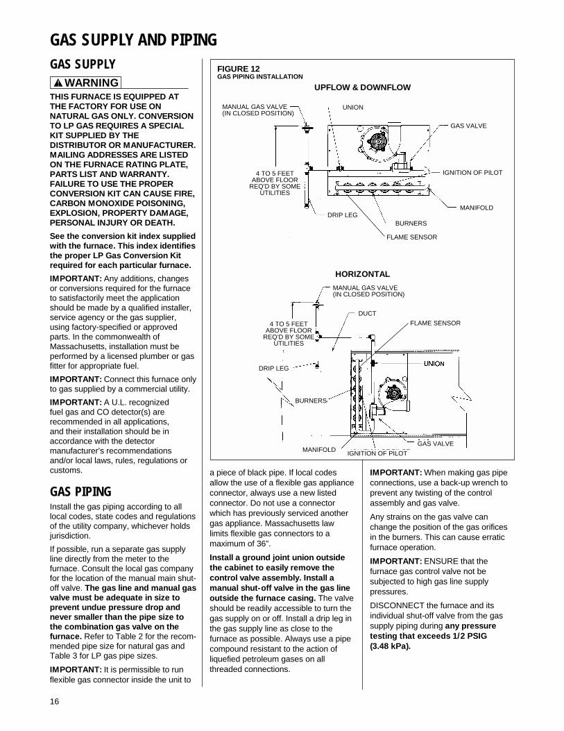
FIGURE 12GAS PIPING INSTALLATION
UPFLOW & DOWNFLOW
GAS SUPPLY AND PIPINGGAS SUPPLY
THIS FURNACE IS EQUIPPED ATTHE FACTORY FOR USE ONNATURAL GAS ONLY. CONVERSIONTO LP GAS REQUIRES A SPECIALKIT SUPPLIED BY THEDISTRIBUTOR OR MANUFACTURER.MAILING ADDRESSES ARE LISTEDON THE FURNACE RATING PLATE,PARTS LIST AND WARRANTY.FAILURE TO USE THE PROPERCONVERSION KIT CAN CAUSE FIRE,CARBON MONOXIDE POISONING,EXPLOSION, PROPERTY DAMAGE,PERSONAL INJURY OR DEATH.
See the conversion kit index suppliedwith the furnace. This index identifiesthe proper LP Gas Conversion Kitrequired for each particular furnace.
IMPORTANT: Any additions, changesor conversions required for the furnaceto satisfactorily meet the applicationshould be made by a qualified installer,service agency or the gas supplier,using factory-specified or approvedparts. In the commonwealth ofMassachusetts, installation must beperformed by a licensed plumber or gasfitter for appropriate fuel.
IMPORTANT: Connect this furnace onlyto gas supplied by a commercial utility.
IMPORTANT: A U.L. recognizedfuel gas and CO detector(s) arerecommended in all applications,and their installation should be inaccordance with the detectormanufacturer’s recommendationsand/or local laws, rules, regulations orcustoms.
GAS PIPINGInstall the gas piping according to alllocal codes, state codes and regulationsof the utility company, whichever holdsjurisdiction.
If possible, run a separate gas supplyline directly from the meter to thefurnace. Consult the local gas companyfor the location of the manual main shut-off valve. The gas line and manual gasvalve must be adequate in size toprevent undue pressure drop andnever smaller than the pipe size tothe combination gas valve on thefurnace. Refer to Table 2 for the recom-mended pipe size for natural gas andTable 3 for LP gas pipe sizes.
IMPORTANT: It is permissible to runflexible gas connector inside the unit to
! WARNING
HORIZONTAL
a piece of black pipe. If local codesallow the use of a flexible gas applianceconnector, always use a new listedconnector. Do not use a connectorwhich has previously serviced anothergas appliance. Massachusetts lawlimits flexible gas connectors to amaximum of 36”.
Install a ground joint union outsidethe cabinet to easily remove thecontrol valve assembly. Install amanual shut-off valve in the gas lineoutside the furnace casing. The valveshould be readily accessible to turn thegas supply on or off. Install a drip leg inthe gas supply line as close to thefurnace as possible. Always use a pipecompound resistant to the action ofliquefied petroleum gases on allthreaded connections.
IMPORTANT: When making gas pipeconnections, use a back-up wrench toprevent any twisting of the controlassembly and gas valve.
Any strains on the gas valve canchange the position of the gas orificesin the burners. This can cause erraticfurnace operation.
IMPORTANT: ENSURE that thefurnace gas control valve not besubjected to high gas line supplypressures.
DISCONNECT the furnace and itsindividual shut-off valve from the gassupply piping during any pressuretesting that exceeds 1/2 PSIG (3.48 kPa).
MANUAL GAS VALVE(IN CLOSED POSITION)
MANUAL GAS VALVE(IN CLOSED POSITION)
FLAME SENSOR
FLAME SENSOR
4 TO 5 FEETABOVE FLOOR
REQ’D BY SOMEUTILITIES
4 TO 5 FEETABOVE FLOOR
REQ’D BY SOMEUTILITIES
UNION
GAS VALVE
IGNITION OF PILOT
MANIFOLD
MANIFOLD IGNITION OF PILOT
GAS VALVE
BURNERS
DUCT
DRIP LEG
DRIP LEG
BURNERS

17
GAS PRESSUREIMPORTANT: The maximum gassupply pressure to the furnace shouldbe 10.5” w.c. for natural gas and 13”w.c. for LP gas.
Natural gas supply pressure shouldoperate between 5" to 10.5” w.c. LPgas supply pressure should be 11” to13” w.c. This pressure must bemaintained with all other gas-firedappliances in operation.
NOTE: Do not exceed a gas pressureof 13” w.c.
ELEVATIONS ABOVE 2000 FTREQUIRE THAT THE FURNACEINPUT RATING BE ADJUSTED ANDTHAT THE SIZE OF THE BURNERORIFICES BE RE-CALCULATEDBASED ON ELEVATION AND GASHEATING VALUE. THE BURNERORIFICES MAY (OR MAY NOT) NEEDTO BE CHANGED. SEE THESECTION TITLED “HIGH ALTITUDEINSTALLATIONS” OF THIS BOOKFOR INSTRUCTIONS.
NEVER PURGE A GAS LINE INTOTHE COMBUSTION CHAMBER.NEVER USE MATCHES, FLAME ORANY IGNITION SOURCE FORCHECKING LEAKAGE. FAILURE TOFOLLOW THIS WARNING CANCAUSE AN EXPLOSION OR FIRERESULTING IN PROPERTYDAMAGE, PERSONAL INJURY ORDEATH.
To check for gas leakage, use anapproved chloride-free soap and watersolution, an electronic combustible gasdetector, or other approved method.
! WARNING
LP CONVERSIONNOTE: For installation, see specific LPkit installation instructions.
The valve can be converted to useliquefied petroleum (LP) gas byreplacing the pressure regulator springwith the conversion kit spring. This LPkit spring allows the regulator tomaintain the proper manifold pressurefor LP gas. The correct burner LPorifices are included in the kit.
NOTE: Order the correct LP conversionkit from the furnace manufacturer.Furnace conversion to LP gas must beperformed by a qualified technician.
ELEVATIONS ABOVE 2000 FTREQUIRE THAT THE FURNACEINPUT RATING BE ADJUSTED ANDTHAT THE SIZE OF THE BURNERORIFICES BE RE-CALCULATEDBASED ON ELEVATION AND GASHEATING VALUE. THE BURNERORIFICES MAY (OR MAY NOT) NEEDTO BE CHANGED. SEE THESECTION TITLED “HIGH ALTITUDEINSTALLATIONS” OF THIS BOOKFOR INSTRUCTIONS.
NOx MODELSWhen converting furnaces equippedwith NOx inserts to LP gas, remove theNOx insert assemblies. Steps forremoval are listed below:
1. Turn off all electrical power and thegas supply to the furnace.
2. Remove the burner door from thefurnace.
3. Remove the igniter assembly –handle with care.
4. Remove the two screws attachingthe NOx insert retainer brackets tothe center panel. Pull the retainerrod.
5. Put the two screws back into theholes in the center panel.
6. Re-install the igniter and burnerassemblies.
7. Replace burner door.
8. Turn on electrical power and gassupply to the unit
CAUTION!
CAUTION!

18
TABLE 3LP GAS PIPE CAPACITY TABLE (CU. FT./HR.)
SETTING GAS PRESSUREThe maximum gas supply pressure tothe furnace should be 10.5” w.c.natural gas, or 13” w.c. LP gas. Theminimum supply gas pressure to thegas valve should be 5" w.c. natural gasor 11" w.c. LP gas. A properlycalibrated manometer is required foraccurate gas pressure measurements.
ELEVATIONS ABOVE 2000 FTREQUIRE THAT THE FURNACEINPUT RATING BE ADJUSTED ANDTHAT THE SIZE OF THE BURNERORIFICES BE RE-CALCULATEDBASED ON ELEVATION AND GASHEATING VALUE. THE BURNERORIFICES MAY (OR MAY NOT)NEED TO BE CHANGED. SEE THESECTION TITLED “HIGH ALTITUDEINSTALLATIONS” OF THIS BOOKFOR INSTRUCTIONS.
Supply Gas Pressure Measurement.A line pressure tap is on the inlet sideof the gas valve.
1. With gas shut off to the furnace atthe manual gas valve outside theunit, remove the input pressure tapplug.
2. Connect a U-Tube manometer tothe pressure tap. See Figure 13.
3. Turn on the gas supply andoperate the furnace and all othergas-fired units on the same gasline as the furnace.
4. Adjust the line gas pressure tosupply:
A. 5” - 10.5” w.c. for natural gas.
B. 11” - 13” w.c. for LP gas.
5. Shut off the gas at the manual gasvalve and remove theU-Tube manometer.
6. Replace the pressure tap plugbefore turning on the gas.
NATURAL GAS:If the supply gas line pressure is abovethe operating range, install an in-linegas regulator to the furnace. If supplygas line pressure is below theoperating range, either remove anyrestrictions in the gas supply piping orenlarge the gas pipe. See Table 2.
LP GAS:If the supply gas line pressure is abovethe operating range, have the LPsupplier reduce the line pressure at theregulator. If supply gas line pressure isbelow operating range, have the LPsupplier adjust the line pressure at theregulator. See Table 3.
NOTE: Depending on the amount of LPvapor and the outdoor ambienttemperature, the LP storage tank mayrequire supplemental heat to maintainproper pressure levels.
FIGURE 13TYPICAL HOSE CONNECTION TO LINE PRESSURE TAP
Maximum capacity of pipe in thousands of BTU per hour of undiluted liquefied petroleum gases (at 11 inches watercolumn inlet pressure).(Based on a Pressure Drop of 0.5 Inch Water Column)
Nominal Length of Pipe, FeetIron PipeSize, Inches 10 20 30 40 50 60 70 80 90 100 125 150
1/2 275 189 152 129 114 103 96 89 83 78 69 63
3/4 567 393 315 267 237 217 196 182 173 162 146 132
1 1,071 732 590 504 448 409 378 346 322 307 275 252
1-1/4 2,205 1,496 1,212 1,039 913 834 771 724 677 630 567 511
1-1/2 3,307 2,299 1,858 1,559 1,417 1,275 1,181 1,086 1,023 976 866 787
2 6,221 4,331 3,465 2,992 2,646 2,394 2,205 2,047 1,921 1,811 1,606 1,496
Example (LP): Input BTU requirement of unit, 150,000Equivalent length of pipe, 60 ft. = 3/4" IPS required.
TABLE 2NATURAL GAS PIPE CAPACITY TABLE (CU. FT./HR.)
Capacity of gas pipe of different diameters and lengths in cu. ft. per hr. with pressure drop of 0.3 in. and specificgravity of 0.60 (natural gas).
Nominal Length of Pipe, FeetIron PipeSize, Inches 10 20 30 40 50 60 70 80
1/2 132 92 73 63 56 50 46 433/4 278 190 152 130 115 105 96 901 520 350 285 245 215 195 180 170
1-1/4 1,050 730 590 500 440 400 370 3501-1/2 1,600 1,100 890 760 670 610 560 530
After the length of pipe has been determined, select the pipe size which will provide the minimum cubic feet per hourrequired for the gas input rating of the furnace. By formula:
Gas Input of Furnace (BTU/HR)Cu. Ft. Per Hr. Required = Heating Value of Gas (BTU/FT3)
The gas input of the furnace is marked on the furnace rating plate. The heating value of the gas (BTU/FT3) may bedetermined by consulting the local natural gas utility or the LP gas supplier.
CAUTION!

TABLE 4
19
ADJUSTING OR CHECKINGFURNACE INPUT
ELEVATIONS ABOVE 2000 FTREQUIRE THAT THE FURNACEINPUT RATING BE ADJUSTED ANDTHAT THE SIZE OF THE BURNERORIFICES BE RE-CALCULATEDBASED ON ELEVATION AND GASHEATING VALUE. THE BURNERORIFICES MAY (OR MAY NOT) NEEDTO BE CHANGED. SEE THE SECTIONTITLED “HIGH ALTITUDEINSTALLATIONS” OF THIS BOOKFOR INSTRUCTIONS.
NATURAL GAS:The maximum gas supply pressure tothe furnace should be 10.5” W.C. fornatural gas. The minimum gas supplypressure for purposes of inputadjustment to the furnace should be 5”W.C.A properly calibrated manometer orgauge is required for accurate gaspressure readings.
The manifold pressure should be set at3.5” W.C. for natural gas. Only smallvariations in the gas flow should bemade by means of the pressureregulator adjustment.
To adjust the pressure regulator:
1. Remove the regulator cap.
2. Turn the adjustment screw clockwiseto increase pressure orcounterclockwise to decreasepressure.
3. Replace the regulator cap securely.
LP GAS:Furnaces for use on LP gas, the LP gassupply pressure must be set between11.0” and 13.0” W.C. by means of thetank or branch supply regulators. Thefurnace manifold pressure should be setat 10” W.C. at the gas control valve. Forelevations up to 8,000 feet, rating plateinput ratings apply. For above 2,000 ft.altitudes and for any necessary majorchanges in the gas flow rate the orificespud may need to be changed.
TO CHANGE ORIFICE SPUDS:
1. Shut off the manual main gas valveand remove the gas manifold.
2. Replace the orifice spuds.
3. Reassemble in reverse order.
4. Turn the gas supply back on andcheck for proper operation andmanifold pressure.
Check of input is important to preventover firing of the furnace beyond itsdesign-rated input. NEVER SET INPUTABOVE THAT SHOWN ON THERATING PLATE.
TO CHECK FURNACE INPUT:
1. Make certain that all other gasappliances are shut off, with theexception of pilot burners.
2. Start the furnace
3. Time the meter to measure the timerequired to burn one cubic foot ofgas.
4. Use Table 4 to determine input rate.
ORIFICE ORDERINGINFORMATIONOrifice sizes are selected by adding the2-digit drill size required in the orificepart number. Drill sizes available are 39through 64; metric sizes available1.10mm (-90) and 1.15mm (-91):
Orifice Part Number 62-22175-(drillsize)
Example 1:# 60 drill size orifice requiredPart # 62-22175-60
Example 2:1.15mm drill size orifice requiredPart # 62-22175-91
METER TIME IN MINUTES AND SECONDS FOR NORMALINPUT RATING OF FURNACES EQUIPPED FOR NATURAL OR LP GAS
INPUTBTU/HR
METERSIZE
CU. FT.
HEATING VALUE OF GAS BTU PER CU. FT.900 1000 1040 1100 2500
MIN. SEC. MIN. SEC. MIN. SEC. MIN. SEC. MIN. SEC.ONE 1 5 1 12 1 15 1 18 3 2050,000 TEN 10 50 12 00 12 30 13 12 30 00
ONE 0 44 0 48 0 50 0 53 2 075,000 TEN 7 12 8 0 8 19 8 48 20 0
ONE 0 33 0 36 0 38 0 40 1 30100,000 TEN 5 24 6 0 6 15 6 36 15 0
ONE 0 26 0 29 0 30 0 32 1 12125,000 TEN 4 19 4 48 5 0 5 17 12 0
ONE 0 31 0 24 0 25 0 26 1 0150,000 TEN 3 36 4 0 4 10 4 20 10 0
Heating Value of Gas (BTU/Ft3) x 3600 x correction factorInput BTU/HR =
Time in Seconds (for 1 cu.ft.) of Gas
CAUTION!

20
ELECTRICAL WIRING
TURN OFF ELECTRIC POWER ATTHE FUSE BOX OR SERVICE PANELBEFORE MAKING ANYELECTRICAL CONNECTIONS.
ALSO, THE GROUND CONNECTIONMUST BE COMPLETED BEFOREMAKING LINE VOLTAGECONNECTIONS. FAILURE TO DOSO CAN RESULT IN ELECTRICALSHOCK, SEVERE PERSONALINJURY OR DEATH.
IMPORTANT: The furnace must beinstalled so that the electricalcomponents are protected from water(furnace condensate).
ELECTRICAL CONNECTIONS
THE CABINET MUST BEPERMANENTLY GROUNDED. AGROUND SCREW IS PROVIDED INTHE JUNCTION BOX FOR THISPURPOSE. FAILURE TO DO SO CANRESULT IN FIRE, ELECTRICALSHOCK, PERSONAL INJURY ORDEATH.
The electrical supply requirements arelisted on the furnace rating plate.
Use a separate fused branch electricalcircuit containing a properly sized fuseor circuit breaker. Run this circuitdirectly from the main switch box to anelectrical disconnect which must bereadily accessible and located withinsight of the furnace. Connect from thedisconnect to the junction box on theleft side of the furnace, inside thecontrol compartment. See appropriatewiring diagram.
NOTE: The electrical junction boxinside the furnace control compartmentmay be relocated to the right side ifnecessary. A knockout is provided.
NOTE: L1 (hot) and neutral polaritymust be observed when making fieldconnections to the furnace. Theignition control on electric ignitionmodels will not sense flame if L1 andneutral are reversed.
WARNING!
WARNING!
THERMOSTATThe room thermostat must becompatible with the integrated furnacecontrol on the furnace. All thermostatsavailable from the furnacemanufacturer’s Parts Department areacceptable. Generally, all thermostatsthat are not of the “current robbing”type are compatible with the integratedfurnace control used.
NOTE: An isolation relay (relay number42-25104-01) may assist with “currentrobbing” type thermostat compatibilityproblems. Use a single-pole, single-throw relay with a 24-volt AC coil. Thecontacts should be rated for .5 ampsminimum at 24 volts. See Figure 14.
Install the room thermostat inaccordance with the instruction sheetin the box with the thermostat. Run thethermostat lead wires inside the controlcompartment. Connect the thermostatas shown on the wiring diagram. Neverinstall the thermostat on an outsidewall or where it will be influenced bydrafts, concealed hot or cold waterpipes, lighting fixtures, radiation fromfireplace, rays of sun, lamps, television,radios or air streams from registers.Refer to the instructions packed withthe thermostat for best anticipatoradjustment or selection or see below.
HEAT ANTICIPATOR SETTINGS
For adjusting the thermostat heatanticipator setting; (a) add the currentdraw of the various components in thesystem or (b) using jumper wire,measure the current flow between theR and W thermostat circuits. Set thethermostat heat anticipator accordingto the current flow measured.
Installation of the electric supply lineshould be in accordance with theNational Electric Code ANSI/NFPA No.70, latest edition, or CanadianElectrical Code Part 1 - CSA StandardC22.1 and local building codes.
This can be obtained from:
National Fire Protection AssociationBatterymarch ParkQuincy, MA 02269
Canadian Standards Association178 Rexdale Blvd.Etobicoke (Toronto), Ontario
Canada M9W, 1R3
FIGURE 14ISOLATION RELAY
ST-A0804-01

21
FIELD INSTALLED OPTIONACCESSORIESELECTRONIC AIR CLEANER1. Electronic air cleaner line voltage
power can be supplied from thescrew terminal “EAC” and a linevoltage neutral screw terminal onthe control board. See Figure 15.
NOTE: For 80PJ and 80LJ units spadeterms only are provided for E.A.C. andhumidifier. This will power theelectronic air cleaner whenever thecirculating air blower is in operation.
HUMIDIFIER2. Humidifier line voltage power can be
supplied from screw terminal “HUM”to a line voltage neutral screwterminal on the control board. SeeFigure 15. This will power thehumidifier whenever the inducer isoperating in the heating mode.
NOTE: 80PJ and 80LJ models do nothave an output for a humidifier.
NOTE: Maximum current –1.0 ampsfor each option.
FURNACE TWINNINGINSTALLATIONSIMPORTANT: Twinning of 80PJ and80LJ units requires an accessorytwinning kit. Refer to the furnacespecification sheet for proper kit. Do notattempt to twin these models by usingthe instructions below.
IMPORTANT: Only twin furnaces withidentical control boards. 1 thermostatper 2 furnaces.
IMPORTANT: Only bottom returns canbe used. No more than two furnacescan share the same supply and return.Furnaces must have same heating andblower capacity. Twinning furnacesmust operate off the same phase ofpower.
Twinning operation of two furnaces,installed side-by-side, connected by acommon duct system with main powersupplied by the same source, andcontrolled by a common thermostat canbe done with the UT ELECTRONICCONTROLS 1028-928 integratedcontrol boards.
The “OK” LED will flash if twinning isnot set up properly.
UT ELECTRONIC CONTROLS 1028-928 CONTROL BOARD1. Single Stage Operation
(See Figure 16)a. Control board "ONE" is on
furnace connected to thethermostat.
b. The 24 VAC supply to bothcontrol boards must be in phasewith each other.
c. Connect the "C," "W" and"TWIN" terminals tocounterparts on each control.
d. Both control boards must haveswitch #3 in the "ON" position.
2. Two Stage Operation(See Figure 17)
a. Follow above instructions.Connect "W2" on thermostat to"W" on control board "TWO".
FIGURE 15LINE VOLTAGE CONNECTIONS
UT ELECTRONIC CONTROLS 1028-928 CONTROL BOARDS
UT ELECTRONIC CONTROLS 1012-925 CONTROL BOARD
I677
INVENSYS CLIMATE CONTROLS ICC-H1MC7

22
I400
FIGURE 16UT Electronic Controls 1028-928 CONTROL BOARD, TWINNING CONNECTION -- SINGLE STAGE OPERATION
a099201

23
FIGURE 17UTEC 1028-928 CONTROL BOARD, TWINNING CONNECTION -- TWO-STAGE OPERATION
a099301

24
80+ HIGH ALTITUDEINSTRUCTIONS
THE NATIONAL FUEL GAS CODE(NFGC) GUIDELINES SHOULD BEFOLLOWED WHEN CONVERTINGTHESE FURNACES FOR HIGHALTITUDE OPERATION.
ELEVATIONS ABOVE 2000 FTREQUIRE THAT THE FURNACEINPUT RATING BE ADJUSTED ANDTHAT THE SIZE OF THE BURNERORIFICES BE RE-CALCULATEDBASED ON ELEVATION AND GASHEATING VALUE. THE BURNERORIFICES MAY (OR MAY NOT) NEEDTO BE CHANGED. THE FOLLOWINGEXAMPLES SHOW HOW TODETERMINE IF AN ORIFICE CHANGEWILL BE NECESSARY AND HOW TODETERMINE THE NEW ORIFICESIZE.
IN CANADA, AS AN ALTERNATIVETO ADJUSTING THE BURNERORIFICE SIZE, THE MANIFOLD GASPRESSURE MAY BE ADJUSTED.THIS METHOD IS COVERED LATERIN THIS SECTION. THIS METHOD OFADJUSTING MANIFOLD PRESSUREMAY ONLY BE USED IN CANADIANINSTALLATIONS.
34" 80 Plus furnaces installed above2,000 ft. require the furnace to be de-rated 4% per thousand feet.
NOTE: The factory installed pressureswitch is good at all elevations. It will notneed to be changed.
NOTE: Factory installed orifices arecalculated and sized based on a sealevel Natural Gas heating value of 1075BTU per cubic ft.
Following are examples of orifice sizingusing the National Fuel Gas CodeAppendix F. For a simplified estimationof orifice size based on heating valueand elevation, use Tables 5 and 6.However, calculations are the bestmethod.
Example: 900 BTU/ft3 RegionalNatural Gas Heating Value
I / H = Q25000 / 900 = 27.78 ft.3
I = Sea Level input (per burner): 25000H = Sea Level Heating Value: 900Q = 27.78 ft.3 Natural Gas per hour.
From Table F.1 of National Fuel GasCode Handbook, 2002 (3.5� w.c.column).Orifice required at Sea Level: #40
Natural Gas Orifice Drill Size (4% per 1000 ft. De-Rate)IMPORTANT: 80+ Models only. Do not use this chart for any 90+ Models.
Burner Input (per burner) 25,000 BTU @ Sea Level
Sea level 2000 to 3000 to 4000 to 5000 to 6000 to 7000 to 8000 toto 1999 ft 2999 ft 3999 ft 4999 ft 5999 ft 5999 ft 7999 ft 8999 ft
38 39 40 41 41 42 42 4340 41 42 42 42 43 43 4441 42 42 42 43 43 44 4442 42 43 43 43 44 44 4543 44 44 44 45 45 46 47
Annual Avg. HeatValue (btu per ft3)
850900975
10751170
TABLE 5
From Table F.4 of National Fuel GasCode Handbook, 2002Orifice required at 5000 ft. elevation(4% de-rate per thousand ft.): #42Orifice required at 8000 ft. elevation(4% de-rate per thousand ft.): #44Example: 1050 BTU/ft3 RegionalNatural Gas Heating Value
I / H = Q25000 / 1050 = 23.81 ft.3
I = Sea Level input (per burner): 25000H = Sea Level Heating Value: 1050Q = 23.81 ft.3 Natural Gas per hour.
From Table F.1 of National Fuel GasCode Handbook, 2002 (3.5� w.c.column).Orifice required at Sea Level: #43
From Table F.4 of National Fuel GasCode Handbook, 2002Orifice required at 5000 ft. elevation(4% de-rate per thousand ft.): #45Orifice required at 8000 ft. elevation(4% de-rate per thousand ft.): #47
! CAUTION
! CAUTION

25
TA
BLE
6S
UP
PLE
ME
NT
AL
OR
IFIC
E S
IZE
CH
AR
T
80 P
lus
ON
LY m
od
els
wit
h 25
,000
Btu
's p
er B
urne
r. D
O N
OT
US
E T
HIS
CH
AR
T F
OR
AN
Y 9
0 P
LUS
MO
DE
L.N
AT
UR
AL
GA
S Q
UIC
K R
EF
ER
EN
CE
CH
AR
T F
OR
OR
IFIC
E S
ELE
CT
ION
, AT
3.5
" W
.C. A
ND
AP
PR
OX
IMA
TE
FIN
AL
FIR
ING
RA
TE
S
Sea
Le
vel
Orif
ice
Siz
e
Sea
Lev
elC
ubic
Foo
t at
3.5"
W.C
.
80 P
lus
Hea
tV
alue
at
25,0
00 B
tu’s
per
Bur
ner
0-99
910
00-1
999
2000
-299
930
00-3
999
4000
-499
950
00-5
999
6000
-699
970
00-7
999
8000
-899
990
00-9
999
ELE
VA
TIO
N C
HA
RT
(N
FG
rec
omm
ende
d or
ifice
bas
ed o
n 4%
der
ate
for
each
100
0 fo
ot o
f ele
vatio
n, b
ased
on th
e in
ters
ectio
n of
the
orifi
ce r
equi
red
at S
ea L
evel
and
the
elev
atio
n re
quire
d be
low
)
3730
.63
816
3737
3839
3940
4142
4243
3829
.25
855
3838
3940
4141
4242
4343
3928
.288
739
3940
4141
4242
4343
44
4027
.03
925
4040
4142
4242
4343
4444
4125
.98
962
4141
4242
4243
4344
4445
4224
.95
1002
4242
4243
4343
4444
4546
4322
.39
1117
4343
4444
4445
4546
4747
4421
.01
1190
4444
4545
4546
4747
4848
25,0
0024
,000
23,0
0022
,000
21,0
0020
,000
19,0
0018
,000
17,0
0016
,000
All
calc
ulat
ions
are
per
form
ed b
y us
ing
the
fir
st t
hree
co
lum
ns o
f in
form
atio
n o
nly.
Bef
ore
beg
inni
ng a
ny c
alcu
lati
ons
, det
erm
ine
the
ind
ivid
ual b
urne
r B
tu s
ize
and
hea
ting
val
ue a
t S
ea L
evel
fo
r th
e in
stal
lati
on
site
. Eac
h va
lue
sho
wn
in t
he H
eat
Val
ue c
olu
mn
is p
erb
urne
r at
3.5
" W
.C.
NO
TE
: H
eat V
alue
at S
ea L
evel
, for
the
loca
tion
of th
e in
stal
latio
n, is
ava
ilabl
e fr
om th
e N
atur
al G
as S
uppl
ier
to th
at s
ite. O
rific
es fo
r al
l alti
tude
s ar
e ba
sed
on S
ea L
evel
val
ues.
Div
ide
the
indi
vidu
al b
urne
r ca
paci
ty (
25,0
00 fo
r 80
plu
s) b
y th
e H
eat V
alue
for
the
site
to d
eter
min
e th
e C
ubic
Foo
t val
ue a
t Sea
Lev
el, o
r di
vide
burn
er c
apac
ity b
y th
e C
ubic
Foo
t val
ue fo
r th
e H
eat V
alue
. Onc
e yo
u ha
ve e
ither
the
Cub
ic F
oot V
alue
or
the
Hea
t Val
ue y
ou c
an e
stim
ate
the
Sea
Leve
l orif
ice
for
the
site
. To
sele
ct th
e co
rres
pond
ing
high
alti
tude
orif
ice,
loca
te th
e si
te e
leva
tion
on th
e ch
art a
bove
and
the
orifi
ce r
equi
red
at S
eaLe
vel f
rom
you
r ca
lcul
atio
n in
the
first
col
umn.
The
cor
rect
hig
h al
titud
e or
ifice
that
mus
t be
inst
alle
d in
eac
h in
divi
dual
bur
ner
is th
e in
ters
ectio
n of
thes
e tw
o po
ints
on
the
char
t abo
ve.
Fin
al F
iring
Rat
e pe
r B
urne
r

26
LP GASLP Gas is a manufactured gas that hasconsistent heating value across mostregions.
The NFGC guidelines are used with thefollowing exception:
The recommended LP Gas high altitudeorifice selections differ slightly in that theNFGC LP orifice chart, as they are notaccurate for ICECO products. TheNational Fuel Gas Code LP orifices arebased on an 11" of water columnpressure at the orifice, which differs fromICECO products that use 10" of watercolumn at the orifice. This differencerequires a deviation from the NFGCorifice size recommendations. The SeaLevel input should still be reduced by 4%per thousand ft. and the orifice size mustbe selected based on the reduced inputselection chart below.
ORIFICE ORDERINGINFORMATIONOrifice sizes are selected by adding the2-digit drill size required in the orificepart number. Drill sizes available are 39through 64; metric sizes available1.10mm (-90) and 1.15mm (-91):
Orifice Part Number 62-22175-(drillsize)
Example 1:# 60 drill size orifice requiredPart # 62-22175-60
Example 2:1.15mm drill size orifice requiredPart # 62-22175-91.
ALTERNATE METHOD FORCANADIAN HIGH-ALTITUDEDERATEIn Canada, unless an orifice change isspecifically mandated by local codes,an alternate method of altitude derationthrough a reduction in manifoldpressure is acceptable as described inTable 7. This information is based on aheating value of 1000 BTU per cubicfeet of natural gas, and 2500 BTU percubic feet of LP gas.
IMPORTANT: Actual input rates mustbe measured onsite with manifoldpressure adjustment to ensure that anactual 10% reduction in input rate isachieved.
Once this field adjustment has beenmade, the label shown in Figure 18rmust be affixed in a conspicuouslocation on the front of the furnacecabinet.
NOTE: This label is supplied in theinformation packet shipped with eachfurnace.
LP GAS ORIFICE DRILL SIZE(4% PER 1000 FT DE-RATE)IMPORTANT: 80+ MODELS ONLY. DO NOTUSE THIS CHART FOR ANY 90+ MODELS.
Input (per OrificeAltitude burner) 25000 Size
0 to 2000 ft. 25000 #542000�-3000� 24000 #543000�-4000� 23000 #544000�-5000� 22000 #545000�-6000� 21000 #546000�-7000� 20000 #547000�-8000� 19000 #558000�-9000� 18000 #559000�-10000� 17000 #55
TABLE 7ALTERNATE METHOD FOR CANADIAN HIGH-ALTITUDE DERATE
IMPORTANT: 80+ Models only. Do not use this chart for any 90+ Models.NATURAL GAS LP GAS
FIGURE 18MANIFOLD PRESSURE-CHANGE LABEL
THE MANIFOLD PRESSURE OF THIS APPLIANCE HAS BEEN FIELD ADJUSTED TO OBTAIN THE CORRECT INPUT RATING FOR INSTALLATION AT ALTITUDES
BETWEEN 2,000 FEET AND 4,500 FEET ELEVATION.
LA PRESSION DU DISTRIBUTEUR D'ALIMENTATION DE CET APPAREIL A ÉTÉ AJUSTÉ SUR LES LIEUX AFIN D'OBTENIR LA BONNE PUISSANCE D'ENTRÉE POUR
UNE INSTALLATION ENTRE 2000 ET 4500 PIEDS D'ALTITUDE.
92-24399-01-01
ALTITUDE INPUT OUTPUTORIFICE
SIZEMANIFOLDPRESSURE
0’ - 2000’
50,00075,000100,000125,000150,000
40,00060,00080,000100,000120,000
#42 3.5” W.C.
2001’ - 4500’
45,00067,50090,000112,500135,000
36,00054,00072,00090,000108,000
#42 2.9” W.C.
ALTITUDE INPUT OUTPUTORIFICE
SIZEMANIFOLDPRESSURE
0’ - 2000’
50,00075,000100,000125,000150,000
40,00060,00080,000100,000120,000
#54 10” W.C.
2001’ - 4500’
45,00067,50090,000112,500135,000
36,00054,00072,00090,000108,000
#54 8.1” W.C.

27
LIGHTING INSTRUCTIONSThis appliance is equipped with either adirect spark ignition device or a hotsurface silicon carbide ignition device.This device lights the main burners eachtime the room thermostat (closes) calls forheat. See lighting instructions on thefurnace.TO START FURNACE
1. BE SURE THAT THE MANUAL GASCONTROL HAS BEEN IN THE “OFF”POSITION FOR AT LEAST FIVEMINUTES. DO NOT ATTEMPT TOMANUALLY LIGHT THE MAINBURNERS. FAILURE TO FOLLOWTHIS WARNING CAN CAUSE AFIRE OR AN EXPLOSIONRESULTING IN PROPERTYDAMAGE, PERSONAL INJURY ORDEATH.
2. Set the thermostat to lowest setting.3. Turn off all electric power to the
appliance.4. This appliance does not have a pilot.
It is equipped with an ignition devicewhich automatically lights the burner.Do NOT try to light the burner by hand.
5. Remove control door.6. Move switch to the "OFF" position.
NOTE: Use only your hand to movethe gas control switch. Never usetools. If the switch will not move byhand, don't try to repair it; call aqualified service technician. Forceor attempted repair may result in afire or explosion.
7. Wait five (5) minutes to clear out anygas. Then smell for gas, includingnear the floor. If you smell gas, STOP!Follow the safety instructions on thefront page of this manual. If you don'tsmell gas, go to the next step.
8. Move switch from "OFF" position to"ON" position.
9. Replace control door.10.Turn on all electric power to the
appliance.11.Set the thermostat to desired setting.12. If the appliance will not operate, follow
the instructions below to shut downfurnace and call your servicetechnician or gas supplier.
TO TURN OFF GAS TO FURNACE1. Set the thermostat to the lowest setting.2. Turn off all electric power to the
appliance if service is to be performed.3. Remove control door.4. Move switch to the "OFF" position.5. Replace control door.
WARNING!
SHOULD OVERHEATING OCCUR ORTHE GAS SUPPLY FAIL TO SHUTOFF, SHUT OFF THE MANUAL GASVALVE TO THE APPLIANCE BEFORESHUTTING OFF THE ELECTRICALSUPPLY. FAILURE TO DO SO CANCAUSE AN EXPLOSION OR FIRERESULTING IN PROPERTY DAMAGE,PERSONAL INJURY OR DEATH.
SEQUENCE OF OPERATIONUT ELECTRONIC CONTROLS &INVESYS CLIMATE CONTROLSIntegrated Controls with HotSurface Ignition.1. Each time the thermostat “W”
(Heating) contacts close, theinduced draft blower (inducer)begins a prepurge cycle.
2. The air proving negative pressureswitch(es) closes.
3. 5 seconds after the pressureswitch(es) close, the hot surfaceigniter begins heating for 30seconds to full temperature. Theinduced draft blower operates forthe complete heating cycle.
4. After the 30-second igniter warmup, the gas valve opens for an8-second trial for ignition.
5. The igniter lights the gas burnersand stays energized for the first7 seconds after the gas valveopens.
6. 8 seconds after the gas valveopens the remote flame sensormust prove flame ignition for onesecond using the process of flamerectification. If the burners don’tlight, the system goes throughanother ignition sequence. It doesthis up tofour times.
7. The main blower startsapproximately 20 seconds after theburners ignite.
8. When the thermostat “W” (HeatCall) ends, the gas valve closes,the burners go out, the induceddraft blower stops after a 10-second post-purge, and thenegative pressure switch(es) open.
9. The main blower continues untiltimed off by the setting on theintegrated furnace control board.
Sequence if the system doesn’t lightor doesn’t sense flame:1. On a call for heat, the control runs
the inducer for 35 seconds toprepurge.
2. 5 seconds into prepurge, the hotsurface igniter heats for 30seconds. The inducer continues torun.
3. After the 30-second igniter warmup, the gas valve opens for an8-second trial for ignition. Theinducer continues and the igniterstays energized.
4. If flame is not sensed during the8th second after the gas valveopens, the gas valve closes, andthe igniter de-energizes.
5. After a 10-second post-purge, theinducer stops and the controlverifies that the pressure switchhas opened. Once the openpressure switch is confirmed, thecontrol begins the next ignitioncycle by energizing the inducer fora pre-purge of 30 seconds. Afterthe 30-second pre-purge, theigniter energizes and begins a 30-second warm-up period (inducer isstill running). After a 30-secondigniter warm-up period (60 sec. ofind. running), the gas valve opensand the control looks for a flamesignal for up to 8 seconds. If noflame is sensed, the control goesinto “self-healing” mode, in whichthe blower and inducer both run forthree minutes before anotherignition attempt is made.NOTE: The following applies onlyto units manufactured beforethird Quarter 2003: After 5-secondinter-purge, the control begins a30-second pre-purge followed by a30-second igniter warm-up period(inducer is still running). After the30-second igniter warm-up period,the gas valve opens and thecontrol looks for a flame signal forup to 8 seconds. If no flame issensed, the control goes into “self-healing” mode, in which the blowerand inducer both run for threeminutes before another ignitionattempt is made.
6. The control attempts to ignite up tofour times (first attempt followed bythree retries). After the fourthfailure to ignite, the control goesinto a one-hour “soft-lockout,”during which the control will notrespond to the thermostat heat call(W). The lockout can be reset byshutting off main power to thefurnace for five seconds, or byturning the heat call (W) from thethermostat off and then back on.Note that second and fourthignition attempts will have a 30-second pre-purge followed by a 30-second igniter warm-up period.This prevents the igniter fromoverheating.
7. The above sequence will repeatafter a one hour delay. It willcontinue repeating until ignition issuccessful or the call for heat isterminated.
8. To reset the lock out, make andbreak power either at thethermostat or at the unitdisconnect switch for 5 to 10seconds. It then goes throughanother set of trials for ignition.
UT Electronic Controls Direct SparkIgnition
WARNING!
START-UP PROCEDURE

28
FIGURE 19UT Electronic Controls 1012-925Aand Invensys Climate ControlsICC-H1MC7BLOWER OFF TIMINGS
OFF TIME SWITCH 1 SWITCH 2
90 SEC. OFF ON
120 SEC. OFF OFF
160 SEC. ON OFF
180 SEC. ON ON
(TIMER ISRED BLOCKON BOARD)
I335
1. Each time the thermostat contactsclose, the induced draft blower(inducer) begins a prepurge cycle.
2. The air proving negative pressureswitch(es) closes.
3. 30 seconds after the pressureswitch(es) close, the spark igniterenergizes. The induced draftblower operates for the completeheating cycle.
4. After the spark igniter energizes,the gas valve opens for a 8second trial for ignition.
5. The igniter lights the gas burners.6. After the gas valve opens the flame
sensor must prove flame ignitionfor one second using the processof flame rectification. If the burnersdon’t light, the system goes throughanother ignition sequence. It doesthis up to four times.
7. The main blower starts 20 secondsafter the burners ignite.
8. When the thermostat cycle ends,the gas valve closes, the burners goout, the induced draft blower stopsafter a 10-second post-purge, andthe negative pressure switch(es)open.
9. The main blower continues untiltimed off by the setting on theintegrated furnace control board.
Sequence if the system doesn’t lightor doesn’t sense flame:1. On a call for heat, the control runs
the inducer for 30 seconds to pre-purge.
2. After the 30-second pre-purge, thespark igniter energizes. The inducercontinues to run.
3. After the spark igniter energizes, thegas valve opens for an 8-secondtrial for ignition. The inducercontinues and the igniter staysenergized.
4. If flame is not sensed within 8seconds after the gas valve opens,the gas valve closes, the igniter de-energizes and:
5. The inducer completes a 10-secondpost-purge, the inducer stops, andthe control verifies that the pressureswitch has opened. Once the openpressure switch is confirmed, thecontrol begins the next ignition cycleby energizing the inducer for a pre-purge of 30 seconds. After the pre-purge, the igniter energizes and thegas valve opens (inducer continuesto run). If no flame is sensed on thesecond attempt, the control goesinto a “self-healing” mode, in whichthe blower and the inducer run for 3minutes before another ignitionattempt is made.NOTE: The following applies onlyto units manufactured beforethird Quarter 2003: After a 30-second inter-purge (inducer runscontinuously), the igniter isenergized, and the gas valve opensfor 8 seconds. If flame is not sensedin 8 seconds, the gas valve isclosed and the igniter de-energizes.If no flame is sensed on this second
attempt, the control goes into a“self-healing” mode, in which theblower and inducer run for 3minutes before another ignitionattempt is made.
6. The control attempts to ignite up tofour times (first attempt followed bythree retries). After the fourthfailure to ignite, the control goesinto a one-hour “soft-lockout”during which the control will notrespond to the thermostat heat call(W). The lockout can be reset byshutting off main power to thefurnace for five seconds, or byturning the heat call (W) from thethermostat off and then back on.
7. The above sequence will repeatafter a one hour delay. It willcontinue repeating until ignition issuccessful or the call for heat isterminated.
8. To reset the lock out, make andbreak power either at thethermostat or at the unit disconnectswitch for 5 to 10 seconds. It thengoes through another set of trialsfor ignition.
SETTING BLOWER TIMINGSThe UT Electronic Controls andInvensys Climate Controls IFC’s(integrated furnace controls) have fourquick connect terminals for connectingthe motor speed leads. These are:
1. FAN SPEED — motor runs on thisspeed when the thermostat is in the“FAN” position.
2. COOL — connect desired coolingspeed.
3. HEAT — connect desired heatingspeed.
4. HEAT/COOL — connect desiredspeed when heating and coolingspeed are the same.
NOTE: This tap (heat/cool) notavailable on 80PJ or 80LJ.
IMPORTANT: Do not connect anymotor speeds to “HEAT” or “COOL” ifyou use the “HEAT/COOL” terminal.
5. If heating and continuous speedare the same, jump across “FAN”and “HEAT” terminals.
NOTE: This does not apply to 80PJ or80LJ models because the heat tapfunctions as the continuous fan tap aswell.
See Figures 18, 19 & 20 for instructionsfor setting the blower “OFF” timings.
FIGURE 18UT Electronic Controls 1028-928BLOWER OFF TIMINGS
OFF TIME SWITCH 1 SWITCH 2
90 SEC. OFF ON
120 SEC. OFF OFF
160 SEC. ON OFF
180 SEC. ON ON
TW
INS
ING
LENOTE: SWITCH 3 IS USED FORTWINNING APPLICATIONS.
ON
I402
FIGURE 20UT Electronic Controls 1012-925BBLOWER OFF TIMINGS

29
AIR FLOWThe importance of proper air flow overthe heat exchanger cannot be overemphasized.
IT IS IMPORTANT THAT EACHDUCT SYSTEM BE SIZED ANDINSTALLED FOR THE SPECIFICAPPLICATION BY PROPERLYAPPLYING THE APPROPRIATEINDUSTRY ACCEPTED STANDARD.IF LESS THAN MINIMUMSTANDARDS ARE APPLIED, THEEQUIPMENT USER COULD EXPECTTO EXPERIENCE HIGHER UTILITYBILLS, MAJOR COMPONENTFAILURE, VARYING DEGREES OFAIR NOISE OR OTHERUNSATISFACTORY ISSUES, OVERWHICH THE MANUFACTURER HASNO CONTROL.
TEMPERATURE RISE CHECK
To determine if the air flow is correct,make a temperature rise check.
1. Insert a thermometer in the supplyair duct as close to the furnace aspossible yet out of a direct linefrom the heat exchanger. SeeFigure 21.
2. Insert a thermometer in the returnair duct as close to the furnace aspossible.
FIGURE 21TEMPERATURE RISE MEASUREMENT
GAS FURNACE (DIRECTDRIVE) INSTRUCTIONS FORCHANGING BLOWER SPEED
DISCONNECT THE ELECTRICALSUPPLY TO THE FURNACE BEFOREATTEMPTING TO CHANGE THEBLOWER SPEED. FAILURE TO DOSO CAN CAUSE ELECTRICALSHOCK RESULTING IN SEVEREPERSONAL INJURY OR DEATH.
The blower motor is wired for blowerspeeds required for normal operationas shown.
If additional blower speed taps areavailable (leads connected to “M1” and“M2” on the electronic control), speedsmay be changed if necessary to fitrequirements of the particularinstallation. Reconnect the unusedmotor leads to “M1” or “M2.” Checkmotor lead color for speed designation.
Heating speeds should not be reducedwhere it could cause the furnace airtemperature to rise to exceed themaximum outlet air temperaturespecified for the unit.
IMPORTANT: Always check airtemperature rise after changing theheating speed for any reason.
WARNING!
! CAUTION
FIGURE 22TYPICAL FURNACE NAME PLATE

30
BLOWER PERFORMANCE DATA – 80LJ DOWNFLOW MODELS ONLY
BLOWER PERFORMANCE DATA – 80PJ UPFLOW/HORIZONTAL MODELS

31
SAFETY FEATURESLIMIT CONTROLThe high limit cut-off temperature is setat the factory and cannot be adjusted.The temperature setting prevents theair temperature leaving the furnacefrom exceeding the maximum outlet airtemperature, which, if exceeded, willshut the furnace down.
There are several reasons for a limitswitch to open and almost alwaysinvolve low airflow through the furnace.
1. A dirty or restricted air filter.
2. A dirty or restricted cooling coil.
3. Undersized or restricted return airsystem.
4. Undersized or restricted supply airsystem.
5. A problem affecting the mainblower:
A. A wrong speed tap selection.
B. Failing motor bearings.
C. Low voltage to the motor.
D. Dirty blower wheel.
E. Wrong motor rotation.
F. Blower wheel slipping on theF. motor shaft.
6. Overfiring the furnace with too muchgas pressure.
7. Ventilation problems.
FLAME ROLL-OUTSAFETY SWITCHESFurnaces are equipped with safetyswitches to protect against flame roll-out conditions in the burnercompartment, which, if tripped, willterminate the heating cycle. In theevent of a flame roll-out condition, theswitch will shut the furnace down. If aswitch is tripped, it must be manuallyreset. DO NOT jumper or reset thisswitch. If this switch should trip, aqualified installer, service agency orthe gas supplier should be called todiagnose and/or correct the source oftripping. If this unit is mounted in acloset, the door must be closed whenmaking this check.
PRESSURE SWITCHThis furnace is equipped with anormally-open pressure switch thatmonitors pressure conditions within thefurnace vent system during the heatingcycle.
There are several reasons for thepressure switch not to close.
1. An inoperative induced draft blower.
2. A loose or leaky pressure switchhose.
3. A blockage in the vent.
4. Severe downdrafts canceling thedraft from the inducer fan.
5. A leaky gasket at the induced draftblower.
6. Improperly sized or installed vent.
The pressure switch contacts mustopen before the unit can go throughanother heating cycle.
See troubleshooting chart in this bookfor troubleshooting recommendations.
3. Operate the furnace.
4. When the thermometer in thesupply air duct stops rising(approximately five minutes),subtract the return air temperaturefrom the supply air temperature.The difference is the temperaturerise.
5. Compare the measuredtemperature rise to the approvedtemperature rise range listed onthe furnace name plate. SeeFigure 22.
If the measured temperature rise isabove the approved range, the air flowis too low. More air must be moved byspeeding up the blower, by removing
restrictions in the duct system, or byadding more supply or return air duct. Ifthe measured temperature rise is belowthe approved range, the air flow is toomuch. Use lower speed tap on themulti-speed blower.
Ideally the measured temperature riseshould be in the middle of the range.
IMPORTANT: Some high-efficiencyfilters have a greater than normalresistance to airflow. This canadversely affect furnace operation. BESURE TO CHECK AIRFLOW if usingany filter other than factory-providedfilter.

32
LUBRICATION
The indoor blower motor and induceddraft motor are prelubricated by themotor manufacturer and do not requirefurther attention.
The motors must be cleanedperiodically by a qualified installer,service agency, or the gas supplier toprevent the possibility of overheatingdue to an accumulation of dust and dirton the windings or on the motorexterior. Air filters should be keptclean. Dirty filters can restrict airflowand results in motor overheating.
Reference Figure 22 for properremoval of the blower assembly ondownflow models.
FIGURE 23DOWNFLOW BLOWER REMOVAL

33
FIGURE 25BOTTOM RETURN
DISCONNECT MAIN ELECTRICALPOWER TO THE UNIT BEFOREATTEMPTING ANY MAINTENANCE.FAILURE TO DO SO CAN CAUSEELECTRICAL SHOCK RESULTINGIN SEVERE PERSONAL INJURY ORDEATH.
FILTERSNOTE: 80PJ and 80LJ models are notfactory equipped with filters. Filtersmust be field installed.
Filter application and placement arecritical to airflow, which may affect theheating and cooling systemperformance. Reduced airflow canshorten the life of the systems majorcomponents, such as motor, limits,elements, heat exchanger, evaporatorcoil or compressor. Consequently, werecommend that the return air ductsystem have only one filter location.The most common location will beinside the furnace or air handler or afilter base. For systems with a returnair filter grill or multiple filter grills, canhave a filter installed at each of thereturn air openings. DO NOT DOUBLEFILTER THE RETURN AIR DUCTSYSTEM. DO NOT FILTER THESUPPLY AIR DUCT SYSTEM.
If high efficiency filters or electronic aircleaners are used in the system, it is
TABLE 8 FILTER SIZES
MAINTENANCEWARNING!
FIGURE 24RESIZING FILTERS & FRAME
*NOTE: Some filters must beresized to fit certain units andapplications.
SOLID BOTTOM MAY BE ORDERED AS AN OPTION FROM THE FACTORY.
UPFLOW FILTER SIZES
FURNACE INPUT BOTTOM SIDE QUANTITYWIDTH BTUH SIZE SIZE
14 45 & 50 121/4" X 25" 153/4" X 25" 1171/2" 67, 75 & 100 153/4" X 25" 153/4" X 25" 1
21" 100 191/4" X 25" 153/4" X 25" 1241/2" 125 & 150 223/4" X 25" 153/4" X 25" 1
DOWNFLOW FILTER SIZES
FURNACE INPUT SIZE QUANTITYWIDTH BTUH
14" 45 & 50 14" X 20" 1171/2" 67, 75 & 100 12" X 20" 221" 100 12" X 20" 2
241/2" 125 & 150 14" X 20" 2
FILTERROD45-24095-01

34
FIGURE 26FILTER RETAINING ROD (SIDE RETURN)
FIGURE 27DOWNFLOW FILTER INSTALLATION
FILTERROD45-24095-01
FILTER RODSUPPORTANGLEAE-60520-01
FILTER SUPPORTANGLE(SEE ANGLE DETAIL)AE-61883-01
FILTER RODSUPPORTANGLEAE-60520-01
FILTERSUPPORTANGLEAE-61883-01

35
important that the airflow is not reducedto maximize system performance andlife. Always verify that the systemsairflow is not impaired by the filteringsystem that has been installed, byperforming a temperature rise andtemperature drop test.
Keep the air filters clean at all times.Vacuum dirt from filter, wash withdetergent and water, air dry thoroughlyand reinstall.
See Table 8 and Figures 24, 25, 26, and27 for proper filter sizes and locations.
1. 14”- 50,000 BTUH unit requiresremoval of 31/2” segment of filter andframe to get proper width for a bottomfilter.
2. 21”-100,000 BTUH unit requiresremoval of 31/2” segment of filter andframe to get proper width for a sidefilter.
3. 241/2”-125,000 and 150,000 BTUHunits require removal of 7” segment offilter and frame to get proper width fora side filter.
IMPORTANT: Do not operate thesystem without filters. A portion of thedust entrained in the air may temporarilylodge in the air duct runs and at thesupply registers. Any recirculated dustparticles will be heated and charred bycontact with the furnace heatexchanger. This residue will soilceilings, walls, drapes, carpets, andother household articles.
SYSTEM OPERATIONINFORMATIONAdvise The Customer To:1. Keep the air filters clean. The heating
system will operate better, moreefficiently and more economically.
2. Arrange the furniture and drapes sothat the supply air registers and thereturn air grilles are unobstructed.
3. Close doors and windows. This willreduce the heating load on thesystem.
4. Avoid excessive use of kitchen &bathroom exhaust fans.
5. Do not permit the heat generated bytelevision, lamps or radios toinfluence the thermostat operation.
6 Except for the mounting platform,keep all combustible articles threefeet from the furnace and ventsystem.
7. IMPORTANT: Replace all blowerdoors and compartment covers afterservicing the furnace. Do not operatethe unit without all panels and doorssecurely in place.
8. Proper operation of the system withconstant air circulation.
COMBUSTIBLE MATERIAL MUSTNOT BE PLACED ON OR AGAINSTTHE FURNACE JACKET OR WITHINTHE SPECIFIED CLEARANCES OFTHE VENT PIPE. THE AREAAROUND THE FURNACE MUST BEKEPT CLEAR AND FREE OF ALLCOMBUSTIBLE MATERIALSINCLUDING GASOLINE AND OTHERFLAMMABLE VAPORS ANDLIQUIDS. PLACEMENT OFCOMBUSTIBLE MATERIALS ON,AGAINST OR AROUND THEFURNACE JACKET CAN CAUSE ANEXPLOSION OR FIRE RESULTINGIN PROPERTY DAMAGE,PERSONAL INJURY OR DEATH.THE FURNACE OWNER SHOULD BECAUTIONED THAT THE FURNACEAREA MUST NOT BE USED AS ABROOM CLOSET OR FOR ANYOTHER STORAGE PURPOSES.
ANNUAL INSPECTIONThe furnace should operate for manyyears without excessive scale build-upin the flue passageways, however, it isrecommended that a qualified installer,service agency, or the gas supplieractually inspect the flue passageways,the vent system and the main and pilotburners for continued safe operationpaying particular attention todeterioration from corrosion or othersources.
HOLES IN THE VENT PIPE OR HEATEXCHANGER CAN CAUSE TOXICFUMES TO ENTER THE HOMERESULTING IN CARBONMONOXIDE POISONING OR DEATH.THE VENT PIPE OR HEATEXCHANGER MUST BE REPLACEDIF THEY LEAK.
• IMPORTANT: It is recommendedthat at the beginning of the heatingseason and approximately midwayin the heating season a visualinspection be made of the mainburner flames and pilot flame onstanding pilot models for the desiredflame appearance by a qualifiedinstaller, service agency, or the gassupplier.
• IMPORTANT: It is alsorecommended that at the beginningof the heating season, the flamesensor on hot surface ignitionmodels be cleaned with steel woolby a qualified installer, serviceagency, or the gas supplier.
• IMPORTANT: It is recommendedthat an annual inspection andcleaning of all furnace markings bemade to assure legibility. Attach areplacement marking, which can beobtained through the distributor, ifany are found to be illegible ormissing.
IMPORTANT: FOR Nox MODELS –At the beginning of the heating seasona visual inspection of the Nox deviceshould be made to ensure they havenot become obstructed by insectsnests or anything else which mayeffect performance.
REPLACEMENT PARTSContact your local distributor for acomplete parts list. See enclosedsheet.
TROUBLESHOOTINGRefer to Figure 28 for determiningcause of unit problems.
WIRING DIAGRAMFigures 29 and 30 are complete wiringdiagrams for the furnace and powersources.
WARNING!
WARNING!

36
FIGURE 28TROUBLESHOOTING FLOWCHART
GO TOE
WARNINGINTEGRATED FURNACE CONTROL (IFC)TROUBLESHOOTING GUIDE
HAZARDOUS VOLTAGELINE VOLTAGECONNECTIONS
DISCONNECT POWER BEFORE SERVICING.SERVICE MUST BE BY A TRAINED, QUALIFIEDSERVICE TECHNICIAN.
NOTE: Most failures are not due to the IFC. Double check all otherpossibilities, including the ground connection, before replacing the IFC.
NOTE: Always verify gas valve inlet and outlet gaspressure. KEY TO ABBREVIATIONS
IBM = Indoor Blower MotorIDM = Induced Draft MotorIFC = Integrated Furnace ControlPS = Pressure Switch(es)SE = Spark ElectrodeHSI = Hot-Surface IgnitionDSI = Direct-Spark Ignition
FLAME (AMBER) LED CODESOFF = No Flame PresentRAPID BLINK = Unexpected FlameSLOW BLINK = Marginal Flame SenseSTEADY ON = Normal Flame Sense
BLINK CODES (GREEN LED)1 Blink - Soft lockout
Reset System power andstart over from beginning
2 Blinks - PS Circuit opengo to point “F.”
3 Blinks - Limit circuit opengo to point “D.”
4 Blinks - PS Circuit closedGo to point “G.”
5 Blinks - Twin Fault (Optional)*Go to point “H.”
1) Set FAN switch to “AUTO”2) Set thermostat to call for heat (set temp. differ-
ential to greater than 10°F
Does the IDM Energize?
IDM Runs for 30 sec. pre-purge?
Spark Ignitor Electrode (SE) Energizesor HSI Ignitor Glowing?
Does Main Burner Light and stay lit? Is the gas valve energized?
PS dropping out? Check IFC*
Does IBM start on heat speed 20 secondsafter burners light?
Does main burner remain lit untilheat call ends?
Does thermostat maintain reasonable room temperature near setpoint?
Set thermostat to off position (W to C = ØV)
Does gas valve shut off immediately?
Does IDM shut off after ten second post-purge?
Does IBM shut off after a max. of 3 min?
ENDHeat-mode troubleshooting
“POWER” LED ON?
24V on W to IFC?
Is “STATUS” LED blinking,steady-on, or off?
Check IFC*.
Check IFC*.
Does IDM runindefinately.
Does IDM Run for 60 sec. and then off for Five minutes
- Check thermostat in “heat” mode,battery, wire, and connections.
SEE BLINK CODES
- Check 24V at IFC.- Check Fuse.- Check Door Switch and Line Power.- Check Transformer.- Check Breaker.
- Check PS contacts- Check wires for short.- Check IFC*.- Check switches and hoses for
water or moisture
- For Twinned units, check that both IFCs are set for “TWIN” and wiresare connected between “TWIN” terminals.
- Check IFC*.- For twinned units, ensure transformers are in phase.
(if out of phase, flame LED will be dim).- For non-twinned units, ensure “TWIN” is in the single (OFF) position.- For Twinned units – ensure both IFC‘s have same part number.
- Check PS, PS Hoses, and wires.- Check for blocked vent, excessive vent length or elbows, or
blocked heat exchanger.- Check IDM wired correctly.- Ensure against excessive wind, which can open pressure switch.- If downflow 90+, check aux. limit – shoud be closed- Check for intermittent P.S. operation.- Check switches and hoses for water or moisture.
- Check gas supply and manifold pressure.- Ensure L1 and Neutral not swapped on IFC and junction box.- Check SE alignment.- Check orifice or other restrictions to gas flow.- Check flame sense rod (clean with sandpaper).- Check flame carry over.
- Check wires, continuity, and connection between IFC and gas valve.- Ensure 24 V between appropriate pins on connector of IFC.- Ensure manual switch on valve is in the “ON” position.- 90+ check aux. limit open? Should be closed- 90+ upflow models – check drain pressure switch between IFC and
gas valve – should be closed – replace drain pressure switch if drainis not blocked or clear drain if blocked.
- Did a pressure switch open during ignition trial? If yes, go to F- Did a limit open during ignition trial? If yes, go to D- Check line voltage between “HEAT” and “NEUTRAL” on IFC.
- Check wires, connections, and continuity between IFC and IBM.- Check IBM capacitor.- Check IBM.
CHECK:- grounding on IFC and unit.- check for proper polarity between L1 & neutral.- flame sense rod (clean if necessary).- wire continually between flame sense rod and appropriate pin of
connector on IFC- flame carries across all burners, and all burners stay lit.
CHECK:AIRFLOW - ensure no restrictions, such as dirty filter, dampers, closed registers, etc.LIMITS - ensure good wire and connections between IFC and all limits. Make surelimits are not open when circulating air temperature is within a specified range.ROLLOUTS - ensure rollouts or overtemperature limits do not need to be reset. Makesure no flame rollout in burner compartment due to blocked flu or heat exchanger.OVERFIRE - ensure furnace is not overtemperature (temp rise is above stated range).Check gas valve, proper orifice size, gas pressure, etc.
Is Limit circuit or IDM wire through aux. limit open oropening and closing?Note: IFC Status LED should be blinking a Fault Code 3.
Is the IFC sensing a good flame: NOTE:Flame sense light should be steady-onwhen burners are lit. If flame LED blinking,or off, flame sense is low or absent.
Ensure thermostat is properly placed and not improperly affected byregisters, fans, sunlight, heat through walls, pipes, or wires in walls.
- Check heat anticipator setting. Furnace may need an isolation relay.- Check installation instructions under section titled “Isolation Relay” for
details.- Verify correct furnace sizing.
NOTE: If IFC goes into lockout (“STATUS LED will blink code “1”), shutoff main power to unit, wait 30 seconds and then reset power.
PROBLEMSTILL
PRESENT
“STATUS” LEDBLINKING
“FLAME” LED BLINKINGOR STEADY ON
If “E” did notresolve issue
Double check - Is W off at IFC?(W to C = ØV?)
Voltage present at gas valve? - Check gas valve.
SEE BLINK CODES
- Check IFC*.
Check IFC*.
*Most failures are not due to the IFC. Doublecheck all other possibilities, including theground connection or wire connections, beforereplacing the IFC.Ensure TSTAT is not in “FAN” position.
Is “STATUS” LED blinking?Is “FLAME” LED blinking or steady-on?
**System will attempt to light 4 times. Voltageis present at gas valve for only 7 seconds dur-ing each trial for ignition. The entire system willgo into a 1 hour lockout after 4 attempts. Themain blower and IDM will run 180 secondsbetween 2nd and 3rd ignition attempts.
- Check line voltage at IDM.- Check wires and connections between IDM and IFC.- Ensure line voltage on IDM pins of IFC connector.- Check IDM capacitor (90+ only).
CHECK BLINK CODES- Check for open limit or limit circuit.- Check for intermittent PS operation.- Check for vent restrictions.- Ensure vent lengths not excessive or
too small diameter.- Check for blocked heat exchanger.
FOR SPARK IGNITION- Check SE wire & connections.- Clean SE with sandpaper. Replace SE if necessary.- If problem persists, check IFC*.- Check SE gas and proper SE ground.- Check SE wire for spark arcing to metal before electrode.FOR HOT SURFACE IGNITION- Check ignitor connected.- Check ignitor wires.- Check ignitor resistance. If open circuit, low or high resistance, replace.- Check ignitor for fractures or cracking- Check ignitor placement.- If problem persists, check IFC*.
START
REPEAT THIS PROCEDURE UNTIL TROUBLE-FREE OPERATION IS OBTAINED.
NO
NO
NO
If “I” did notresolve issue.
NO NO
NO
NO
NO
NO
NONO
NO
NO
NO
NO
NO
NO
NO
BLINKING
YES
YES
YESYES
YES
YES
YES
YES
YES
YES
YES
YESYES
YES
YES
YES
YES
YES
STEADY-ON
I
D
F
H
E
G
YES
NO
YES
PREPURGE
IGNITION TRIAL
IBM “ON” DELAY
STEADY HEAT
END HEAT CALL
POST-PURGE
IBM “OFF” DELAY
STEADY OFF
NO
OFF
**
92-101654-01-00
GO TOF
GO TOI

37
FIGURE 29FOR MODELS WITH UT ELECTRONIC CONTROLS 1028-928 INTEGRATED FURNACE CONTROL AND DIRECT SPARK IGNITION

38
FIGURE 30FOR MODELS WITH UT ELECTRONIC CONTROLS 1012-925 OR INVENSYS CLIMATE CONTROLS ICC-H1MC7-01 INTEGRATED FURNACE CONTROLAND HOT SURFACE IGNITION

39

40 CM 0604
MANUFACTURED BY ICECO®
5600 OLD GREENWOOD ROAD, FORT SMITH, ARKANSAS, 72908