Embed Size (px)
Citation preview
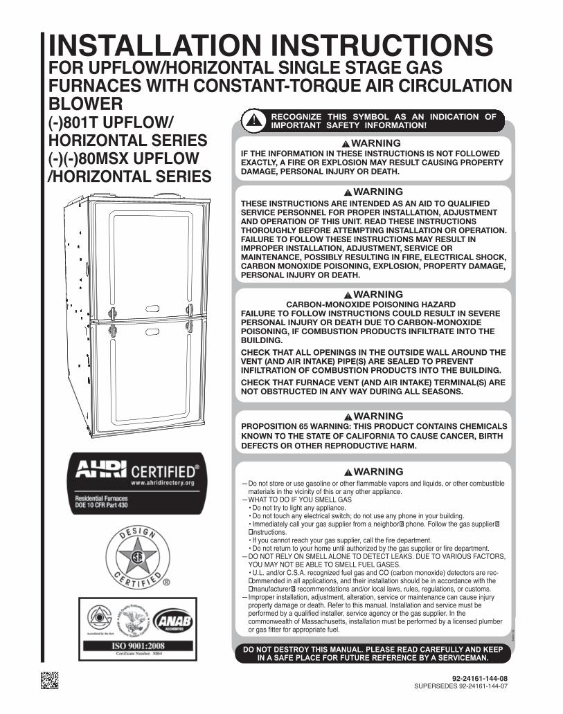
INSTALLATION INSTRUCTIONSFOR UPFLOW/HORIZONTAL SINGLE STAGE GAS FURNACES WITH CONSTANT-TORQUE AIR CIRCULATIONBLOWER(-)801T UPFLOW/HORIZONTAL SERIES(-)(-)80MSX UPFLOW/HORIZONTAL SERIES
ST-A1220-01-X0
92-24161-144-08SUPERSEDES 92-24161-144-07
CARBON-MONOXIDE POISONING HAZARDFAILURE TO FOLLOW INSTRUCTIONS COULD RESULT IN SEVEREPERSONAL INJURY OR DEATH DUE TO CARBON-MONOXIDEPOISONING, IF COMBUSTION PRODUCTS INFILTRATE INTO THEBUILDING.
CHECK THAT ALL OPENINGS IN THE OUTSIDE WALL AROUND THEVENT (AND AIR INTAKE) PIPE(S) ARE SEALED TO PREVENTINFILTRATION OF COMBUSTION PRODUCTS INTO THE BUILDING.
CHECK THAT FURNACE VENT (AND AIR INTAKE) TERMINAL(S) ARENOT OBSTRUCTED IN ANY WAY DURING ALL SEASONS.
THESE INSTRUCTIONS ARE INTENDED AS AN AID TO QUALIFIEDSERVICE PERSONNEL FOR PROPER INSTALLATION, ADJUSTMENTAND OPERATION OF THIS UNIT. READ THESE INSTRUCTIONSTHOROUGHLY BEFORE ATTEMPTING INSTALLATION OR OPERATION.FAILURE TO FOLLOW THESE INSTRUCTIONS MAY RESULT INIMPROPER INSTALLATION, ADJUSTMENT, SERVICE ORMAINTENANCE, POSSIBLY RESULTING IN FIRE, ELECTRICAL SHOCK,CARBON MONOXIDE POISONING, EXPLOSION, PROPERTY DAMAGE,PERSONAL INJURY OR DEATH.
IF THE INFORMATION IN THESE INSTRUCTIONS IS NOT FOLLOWEDEXACTLY, A FIRE OR EXPLOSION MAY RESULT CAUSING PROPERTYDAMAGE, PERSONAL INJURY OR DEATH.
PROPOSITION 65 WARNING: THIS PRODUCT CONTAINS CHEMICALSKNOWN TO THE STATE OF CALIFORNIA TO CAUSE CANCER, BIRTHDEFECTS OR OTHER REPRODUCTIVE HARM.
— Do not store or use gasoline or other flammable vapors and liquids, or other combustible materials in the vicinity of this or any other appliance.— WHAT TO DO IF YOU SMELL GAS • Do not try to light any appliance. • Do not touch any electrical switch; do not use any phone in your building. • Immediately call your gas supplier from a neighbor s̓ phone. Follow the gas supplier s̓ ̓instructions. • If you cannot reach your gas supplier, call the fire department. • Do not return to your home until authorized by the gas supplier or fire department.— DO NOT RELY ON SMELL ALONE TO DETECT LEAKS. DUE TO VARIOUS FACTORS, YOU MAY NOT BE ABLE TO SMELL FUEL GASES. • U.L. and/or C.S.A. recognized fuel gas and CO (carbon monoxide) detectors are rec- ̓ommended in all applications, and their installation should be in accordance with the ̓manufacturer s̓ recommendations and/or local laws, rules, regulations, or customs.— Improper installation, adjustment, alteration, service or maintenance can cause injury property damage or death. Refer to this manual. Installation and service must be performed by a qualified installer, service agency or the gas supplier. In the commonwealth of Massachusetts, installation must be performed by a licensed plumber or gas fitter for appropriate fuel.
2
Cont
ents
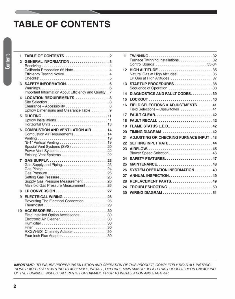
TABLE OF CONTENTS
1 TABLE OF CONTENTS . . . . . . . . . . . . . . . . . . . . . . 2
2 GENERAL INFORMATION . . . . . . . . . . . . . . . . . . . . 3 Receiving . . . . . . . . . . . . . . . . . . . . . . . . . . . . . . . . . . 4 California Proposition 65 Note . . . . . . . . . . . . . . . . . . 4 Efficiency Testing Notice. . . . . . . . . . . . . . . . . . . . . . . 4 Checklist . . . . . . . . . . . . . . . . . . . . . . . . . . . . . . . . . . . 5 3 SAFETY INFORMATION. . . . . . . . . . . . . . . . . . . . . . 6 Warnings. . . . . . . . . . . . . . . . . . . . . . . . . . . . . . . . . . . 6 Important Information About Efficiency and Quality. . 7 4 LOCATION REQUIREMENTS . . . . . . . . . . . . . . . . . 8 Site Selection . . . . . . . . . . . . . . . . . . . . . . . . . . . . . . . 8 Clearance – Accessibility . . . . . . . . . . . . . . . . . . . . . . 8 Upflow Dimensions and Clearance Table . . . . . . . . . 9 5 DUCTING . . . . . . . . . . . . . . . . . . . . . . . . . . . . . . . . . 11 Upflow Installations. . . . . . . . . . . . . . . . . . . . . . . . . . 11 Horizontal Units . . . . . . . . . . . . . . . . . . . . . . . . . . . . 13 6 COMBUSTION AND VENTILATION AIR . . . . . . . . 14 Combustion Air Requirements . . . . . . . . . . . . . . . . . 14 Venting . . . . . . . . . . . . . . . . . . . . . . . . . . . . . . . . . . . 19 “B-1” Vertical Venting . . . . . . . . . . . . . . . . . . . . . . . . 19 Special Vent Systems (SVS) . . . . . . . . . . . . . . . . . . 20 Power Vent Systems . . . . . . . . . . . . . . . . . . . . . . . . 22 Existing Vent Systems . . . . . . . . . . . . . . . . . . . . . . . 22 7 GAS SUPPLY. . . . . . . . . . . . . . . . . . . . . . . . . . . . . . 23 Gas Supply and Piping. . . . . . . . . . . . . . . . . . . . . . . 23 Gas Piping . . . . . . . . . . . . . . . . . . . . . . . . . . . . . . . . 24 Gas Pressure . . . . . . . . . . . . . . . . . . . . . . . . . . . . . . 25 Setting Gas Pressure . . . . . . . . . . . . . . . . . . . . . . . . 26 Supply Gas Pressure Measurement . . . . . . . . . . . . 26 Manifold Gas Pressure Measurement . . . . . . . . . . . 26 8 LP CONVERSION . . . . . . . . . . . . . . . . . . . . . . . . . . 27
9 ELECTRICAL WIRING . . . . . . . . . . . . . . . . . . . . . . 28 Reversing The Electrical Connection. . . . . . . . . . . . 28 Thermostat . . . . . . . . . . . . . . . . . . . . . . . . . . . . . . . . 29 10 ACCESSORIES . . . . . . . . . . . . . . . . . . . . . . . . . . . . 30 Field Installed Option Accessories . . . . . . . . . . . . . . 30 Electronic Air Cleaner. . . . . . . . . . . . . . . . . . . . . . . . 30 Humidifier . . . . . . . . . . . . . . . . . . . . . . . . . . . . . . . . . 30 Filter . . . . . . . . . . . . . . . . . . . . . . . . . . . . . . . . . . . . 30 RXGW-B01 Chimney Adapter . . . . . . . . . . . . . . . . . 30 Four Inch Flue Adapter. . . . . . . . . . . . . . . . . . . . . . . 30
11 TWINNING . . . . . . . . . . . . . . . . . . . . . . . . . . . . . . . . 32 Furnace Twinning Installations. . . . . . . . . . . . . . . . . 32 Control Boards . . . . . . . . . . . . . . . . . . . . . . . . . . 33-34 12 HIGH ALTITUDE . . . . . . . . . . . . . . . . . . . . . . . . . . . 35 Natural Gas at High Altitudes. . . . . . . . . . . . . . . . . . 35 LP Gas at High Altitudes . . . . . . . . . . . . . . . . . . . . . 37 13 STARTUP PROCEDURES . . . . . . . . . . . . . . . . . . . 38 Sequence of Operation . . . . . . . . . . . . . . . . . . . . . . 38 14 DIAGNOSTICS AND FAULT CODES. . . . . . . . . . . 39
15 LOCKOUT . . . . . . . . . . . . . . . . . . . . . . . . . . . . . . . . 40
16 FIELD SELECTIONS & ADJUSTMENTS . . . . . . . 41 Field Selections – Dipswitches . . . . . . . . . . . . . . . . 41 17 FAULT CLEAR. . . . . . . . . . . . . . . . . . . . . . . . . . . . . 42
18 FAULT RECALL . . . . . . . . . . . . . . . . . . . . . . . . . . . 42
19 FLAME STATUS L.E.D.. . . . . . . . . . . . . . . . . . . . . . 42
20 TIMING DIAGRAM . . . . . . . . . . . . . . . . . . . . . . . . . 42
21 ADJUSTING OR CHECKING FURNACE INPUT . 43
22 SETTING INPUT RATE . . . . . . . . . . . . . . . . . . . . . . 44
23 AIRFLOW. . . . . . . . . . . . . . . . . . . . . . . . . . . . . . . . . 45 Blower Speed Selection . . . . . . . . . . . . . . . . . . . . . . 46 24 SAFETY FEATURES. . . . . . . . . . . . . . . . . . . . . . . . 47
25 MAINTENANCE. . . . . . . . . . . . . . . . . . . . . . . . . . . . 48
26 SYSTEM OPERATION INFORMATION . . . . . . . . . 49
27 ANNUAL INSPECTION. . . . . . . . . . . . . . . . . . . . . . 49
28 REPLACEMENT PARTS. . . . . . . . . . . . . . . . . . . . . 49
24 TROUBLESHOOTING . . . . . . . . . . . . . . . . . . . . . . 50
30 WIRING DIAGRAM . . . . . . . . . . . . . . . . . . . . . . . . . 51
IMPORTANT: TO INSURE PROPER INSTALLATION AND OPERATION OF THIS PRODUCT, COMPLETELY READ ALL INSTRUC-TIONS PRIOR TO ATTEMPTING TO ASSEMBLE, INSTALL, OPERATE, MAINTAIN OR REPAIR THIS PRODUCT. UPON UNPACKINGOF THE FURNACE, INSPECT ALL PARTS FOR DAMAGE PRIOR TO INSTALLATION AND START-UP.
ITEM NO. DESCRIPTION
4
3
12
15
14
16
5
17
18
2
1
6
8
9
11
13
7
10
ST-A1220-20-00
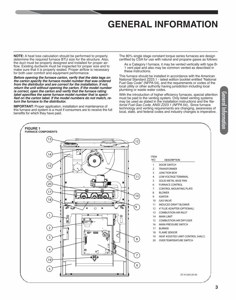
DOOR SWITCHTRANSFORMERJUNCTION BOXLOW VOLTAGE TERMINALSOLID METAL BASE PAN FURNACE CONTROLCONTROL MOUNTING PLATEBLOWERIGNITERGAS VALVEINDUCED DRAFT BLOWER4” FLUE ADAPTER (OPTIONAL)COMBUSTION AIR INLETMAIN LIMITCOMBUSTION AIR DIFFUSERMAIN PRESSURE SWITCHBURNERFLAME SENSORHEAT ASSISTED LIMIT CONTROL (HALC)OVER TEMPERATURE SWITCH
1234567891011121314151617181920
19
20
3
General Information
GENERAL INFORMATION
NOTE: A heat loss calculation should be performed to properlydetermine the required furnace BTU size for the structure. Also,the duct must be properly designed and installed for proper air-flow. Existing ductwork must be inspected for proper size and tomake sure that it is properly sealed. Proper airflow is necessaryfor both user comfort and equipment performance.Before opening the furnace carton, verify that the data tags onthe carton specify the furnace model number that was orderedfrom the distributor and are correct for the installation. If not,return the unit without opening the carton. If the model numberis correct, open the carton and verify that the furnace ratinglabel specifies the same furnace model number that is speci-fied on the carton label. If the model numbers do not match, re-turn the furnace to the distributor.
IMPORTANT: Proper application, installation and maintenance ofthis furnace and system is a must if consumers are to receive the fullbenefits for which they have paid.
The 80% single stage constant torque series furnaces are designcertified by CSA for use with natural and propane gases as follows:
As a Category I furnace, it may be vented vertically with type B-1 vent pipe and also may be common vented as described inthese instructions.
This furnace should be installed in accordance with the AmericanNational Standard Z223.1 - latest edition booklet entitled “NationalFuel Gas Code” (NFPA 54), and the requirements or codes of thelocal utility or other authority having jurisdiction including localplumbing or waste water codes.With the introduction of higher efficiency furnaces, special attentionmust be paid to the venting system. Only listed venting systemsmay be used as stated in the installation instructions and the Na-tional Fuel Gas Code, ANSI Z223.1 (NFPA 54),. Since furnacetechnology and venting requirements are changing, awareness oflocal, state, and federal codes and industry changes is imperative.
ST-A1220-20-00
FIGURE 1FURNACE COMPONENTS
4
Install this furnace in accordance with the American National Stan-dard Z223.1 – latest edition entitled “National Fuel Gas Code”(NFPA54) and requirements or codes of the local utilities or otherauthorities having jurisdiction. This is available from the following:National Fire Protection Association, Inc.Batterymarch ParkQuincy, MA 02269
RECEIVINGImmediately upon receipt, all cartons and contents should be in-spected for transit damage. Units with damaged cartons shouldbe opened immediately. If damage is found, it should be noted onthe delivery papers, and a damage claim filed with the last car-rier. • After unit has been delivered to job site, remove carton taking
care not to damage unit. • Check the unit rating plate for unit size, electric heat, coil, volt-
age, phase, etc. to be sure equipment matches what is re-quired for the job specification.
• Read the entire instructions before starting the installation. • Some building codes require extra cabinet insulation and gas-
keting when unit is installed in attic applications. • If installed in an unconditioned space, apply caulking around
the power wires, control wires, refrigerant tubing and conden-sate line where they enter the cabinet. Seal the power wires onthe inside where they exit conduit opening. Caulking is re-quired to prevent air leakage into and condensate from forminginside the unit, control box, and on electrical controls.
• Install the unit in such a way as to allow necessary access tothe coil/filter rack and blower/control compartment.
• Install the unit in accordance with any local code which mayapply and the national codes. Latest editions are availablefrom: “National Fire Protection Association, Inc., BatterymarchPark, Quincy, MA 02269.” These publications are:
• ANSI/NFPA No. 70-(Latest Edition) National Electrical Code. • NFPA90A Installation of Air Conditioning and Ventilating Sys-
tems. • NFPA90B Installation of warm air heating and air conditioning
systems. • The equipment has been evaluated in accordance with the
Code of Federal Regulations, Chapter XX, Part 3280.
CALIFORNIA RESIDENTS ONLYIMPORTANT: All manufacturer products meet current FederalOSHA Guidelines for safety. California Proposition 65 warningsare required for certain products, which are not covered by theOSHA standards.California's Proposition 65 requires warnings for products sold inCalifornia that contain, or produce, any of over 600 listed chemi-cals known to the State of California to cause cancer or birth de-fects such as fiberglass insulation, lead in brass, and combustionproducts from natural gas.All “new equipment” shipped for sale in California will have labelsstating that the product contains and/or produces Proposition 65chemicals. Although we have not changed our processes, havingthe same label on all our products facilitates manufacturing andshipping. We cannot always know “when, or if” products will besold in the California market.You may receive inquiries from customers about chemicals foundin, or produced by, some of our heating and air-conditioningequipment, or found in natural gas used with some of our prod-ucts. Listed below are those chemicals and substances commonlyassociated with similar equipment in our industry and other manu-facturers.• Glass Wool (Fiberglass) Insulation• Carbon Monoxide (CO)• Formaldehyde• BenzeneMore details are available at the Websites for OSHA (Occupa-tional Safety and Health Administration), at www.osha.gov and theState of California's OEHHA (Office of Environmental Health Haz-ard Assessment), at www.oehha.org. Consumer education is im-portant since the chemicals and substances on the list are foundin our daily lives. Most consumers are aware that products pres-ent safety and health risks, when improperly used, handled andmaintained.
EFFICIENCY TESTING NOTICEFor purposes of verifying or testing efficiency ratings, thetest procedure in Title 10 APPENDIX N to Subpart B ofPart 430 (Uniform Test Method for Measuring the EnergyConsumption of Furnaces and Boilers) and the clarifyingprovisions provided in the AHRI Operations Manual forResidential Furnaces that were applicable at the date ofmanufacture should be used for test set up and perform-ance.
GENERAL INFORMATION (cont.)
Gene
ral In
form
ation
5
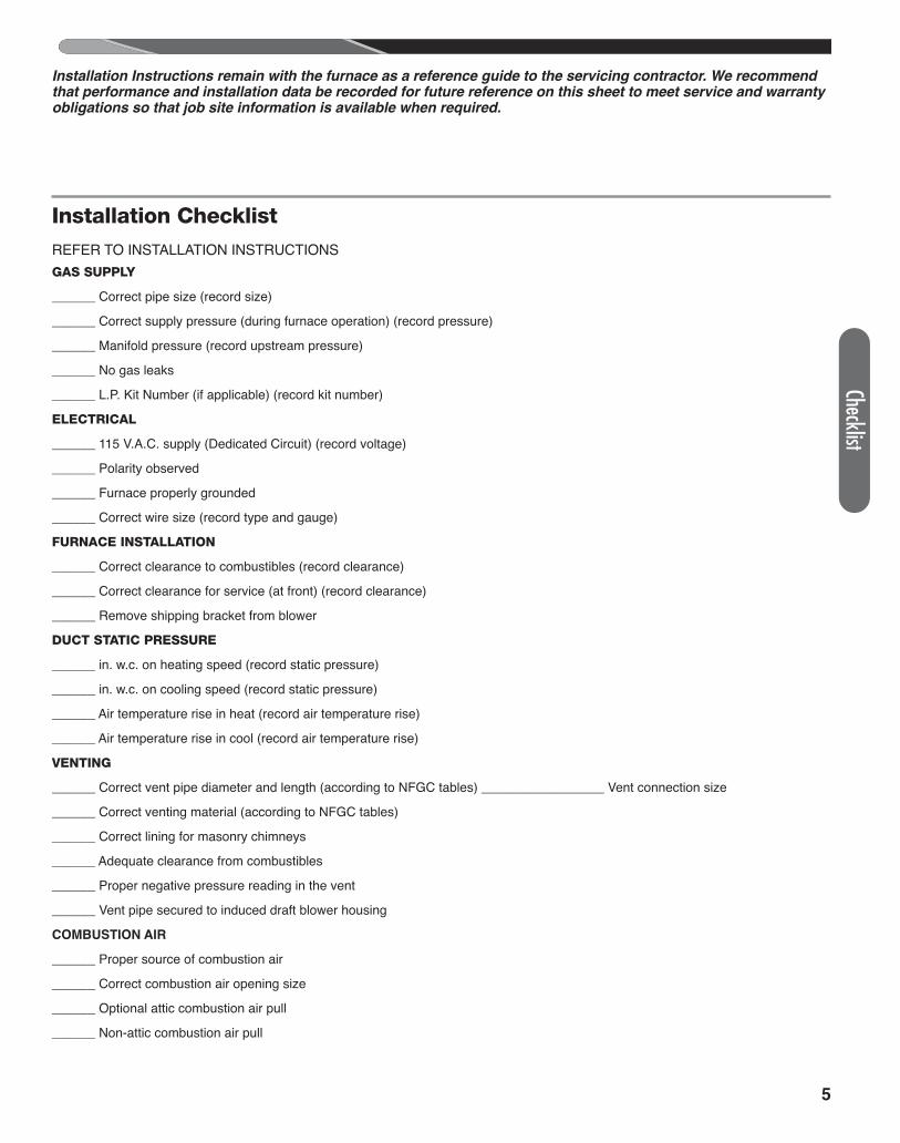
Installation ChecklistREFER TO INSTALLATION INSTRUCTIONSGAS SUPPLY
______ Correct pipe size (record size)
______ Correct supply pressure (during furnace operation) (record pressure)
______ Manifold pressure (record upstream pressure)
______ No gas leaks
______ L.P. Kit Number (if applicable) (record kit number)
ELECTRICAL
______ 115 V.A.C. supply (Dedicated Circuit) (record voltage)
______ Polarity observed
______ Furnace properly grounded
______ Correct wire size (record type and gauge)
FURNACE INSTALLATION
______ Correct clearance to combustibles (record clearance)
______ Correct clearance for service (at front) (record clearance)
______ Remove shipping bracket from blower
DUCT STATIC PRESSURE
______ in. w.c. on heating speed (record static pressure)
______ in. w.c. on cooling speed (record static pressure)
______ Air temperature rise in heat (record air temperature rise)
______ Air temperature rise in cool (record air temperature rise)
VENTING
______ Correct vent pipe diameter and length (according to NFGC tables) _________________ Vent connection size
______ Correct venting material (according to NFGC tables)
______ Correct lining for masonry chimneys
______ Adequate clearance from combustibles
______ Proper negative pressure reading in the vent
______ Vent pipe secured to induced draft blower housing
COMBUSTION AIR
______ Proper source of combustion air
______ Correct combustion air opening size
______ Optional attic combustion air pull
______ Non-attic combustion air pull
ChecklistInstallation Instructions remain with the furnace as a reference guide to the servicing contractor. We recommendthat performance and installation data be recorded for future reference on this sheet to meet service and warrantyobligations so that job site information is available when required.
Safe
ty In
form
ation
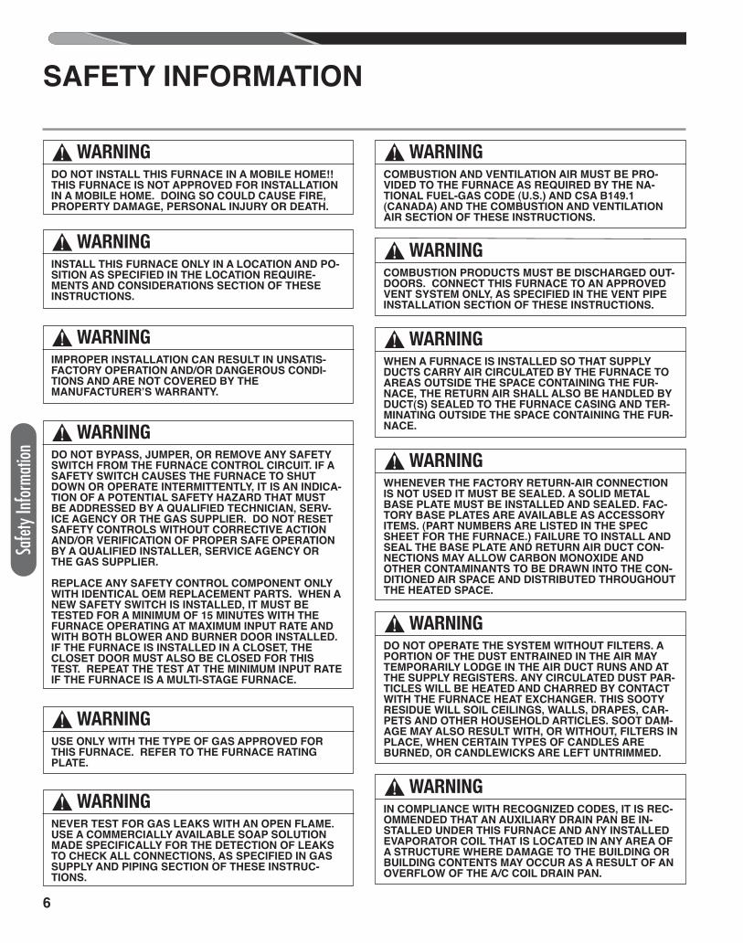
SAFETY INFORMATION
! WARNINGIN COMPLIANCE WITH RECOGNIZED CODES, IT IS REC-OMMENDED THAT AN AUXILIARY DRAIN PAN BE IN-STALLED UNDER THIS FURNACE AND ANY INSTALLEDEVAPORATOR COIL THAT IS LOCATED IN ANY AREA OFA STRUCTURE WHERE DAMAGE TO THE BUILDING ORBUILDING CONTENTS MAY OCCUR AS A RESULT OF ANOVERFLOW OF THE A/C COIL DRAIN PAN.
! WARNINGDO NOT INSTALL THIS FURNACE IN A MOBILE HOME!!THIS FURNACE IS NOT APPROVED FOR INSTALLATIONIN A MOBILE HOME. DOING SO COULD CAUSE FIRE,PROPERTY DAMAGE, PERSONAL INJURY OR DEATH.
! WARNINGINSTALL THIS FURNACE ONLY IN A LOCATION AND PO-SITION AS SPECIFIED IN THE LOCATION REQUIRE-MENTS AND CONSIDERATIONS SECTION OF THESEINSTRUCTIONS.
! WARNINGIMPROPER INSTALLATION CAN RESULT IN UNSATIS-FACTORY OPERATION AND/OR DANGEROUS CONDI-TIONS AND ARE NOT COVERED BY THEMANUFACTURER’S WARRANTY.
! WARNINGDO NOT BYPASS, JUMPER, OR REMOVE ANY SAFETYSWITCH FROM THE FURNACE CONTROL CIRCUIT. IF ASAFETY SWITCH CAUSES THE FURNACE TO SHUTDOWN OR OPERATE INTERMITTENTLY, IT IS AN INDICA-TION OF A POTENTIAL SAFETY HAZARD THAT MUSTBE ADDRESSED BY A QUALIFIED TECHNICIAN, SERV-ICE AGENCY OR THE GAS SUPPLIER. DO NOT RESETSAFETY CONTROLS WITHOUT CORRECTIVE ACTIONAND/OR VERIFICATION OF PROPER SAFE OPERATIONBY A QUALIFIED INSTALLER, SERVICE AGENCY ORTHE GAS SUPPLIER.
REPLACE ANY SAFETY CONTROL COMPONENT ONLYWITH IDENTICAL OEM REPLACEMENT PARTS. WHEN ANEW SAFETY SWITCH IS INSTALLED, IT MUST BETESTED FOR A MINIMUM OF 15 MINUTES WITH THEFURNACE OPERATING AT MAXIMUM INPUT RATE ANDWITH BOTH BLOWER AND BURNER DOOR INSTALLED.IF THE FURNACE IS INSTALLED IN A CLOSET, THECLOSET DOOR MUST ALSO BE CLOSED FOR THISTEST. REPEAT THE TEST AT THE MINIMUM INPUT RATEIF THE FURNACE IS A MULTI-STAGE FURNACE.
! WARNINGUSE ONLY WITH THE TYPE OF GAS APPROVED FORTHIS FURNACE. REFER TO THE FURNACE RATINGPLATE.
! WARNINGNEVER TEST FOR GAS LEAKS WITH AN OPEN FLAME.USE A COMMERCIALLY AVAILABLE SOAP SOLUTIONMADE SPECIFICALLY FOR THE DETECTION OF LEAKSTO CHECK ALL CONNECTIONS, AS SPECIFIED IN GASSUPPLY AND PIPING SECTION OF THESE INSTRUC-TIONS.
! WARNINGCOMBUSTION PRODUCTS MUST BE DISCHARGED OUT-DOORS. CONNECT THIS FURNACE TO AN APPROVEDVENT SYSTEM ONLY, AS SPECIFIED IN THE VENT PIPEINSTALLATION SECTION OF THESE INSTRUCTIONS.
! WARNINGWHEN A FURNACE IS INSTALLED SO THAT SUPPLYDUCTS CARRY AIR CIRCULATED BY THE FURNACE TOAREAS OUTSIDE THE SPACE CONTAINING THE FUR-NACE, THE RETURN AIR SHALL ALSO BE HANDLED BYDUCT(S) SEALED TO THE FURNACE CASING AND TER-MINATING OUTSIDE THE SPACE CONTAINING THE FUR-NACE.
! WARNINGWHENEVER THE FACTORY RETURN-AIR CONNECTIONIS NOT USED IT MUST BE SEALED. A SOLID METAL BASE PLATE MUST BE INSTALLED AND SEALED. FAC-TORY BASE PLATES ARE AVAILABLE AS ACCESSORYITEMS. (PART NUMBERS ARE LISTED IN THE SPECSHEET FOR THE FURNACE.) FAILURE TO INSTALL ANDSEAL THE BASE PLATE AND RETURN AIR DUCT CON-NECTIONS MAY ALLOW CARBON MONOXIDE ANDOTHER CONTAMINANTS TO BE DRAWN INTO THE CON-DITIONED AIR SPACE AND DISTRIBUTED THROUGHOUTTHE HEATED SPACE.
! WARNINGDO NOT OPERATE THE SYSTEM WITHOUT FILTERS. APORTION OF THE DUST ENTRAINED IN THE AIR MAYTEMPORARILY LODGE IN THE AIR DUCT RUNS AND ATTHE SUPPLY REGISTERS. ANY CIRCULATED DUST PAR-TICLES WILL BE HEATED AND CHARRED BY CONTACTWITH THE FURNACE HEAT EXCHANGER. THIS SOOTYRESIDUE WILL SOIL CEILINGS, WALLS, DRAPES, CAR-PETS AND OTHER HOUSEHOLD ARTICLES. SOOT DAM-AGE MAY ALSO RESULT WITH, OR WITHOUT, FILTERS INPLACE, WHEN CERTAIN TYPES OF CANDLES AREBURNED, OR CANDLEWICKS ARE LEFT UNTRIMMED.
6
! WARNINGCOMBUSTION AND VENTILATION AIR MUST BE PRO-VIDED TO THE FURNACE AS REQUIRED BY THE NA-TIONAL FUEL-GAS CODE (U.S.) AND CSA B149.1(CANADA) AND THE COMBUSTION AND VENTILATIONAIR SECTION OF THESE INSTRUCTIONS.
7
SAFETY
Safety Information
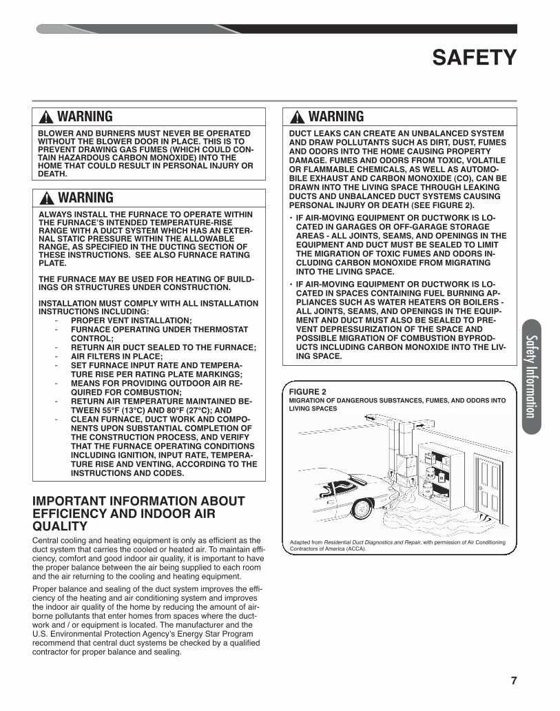
IMPORTANT INFORMATION ABOUTEFFICIENCY AND INDOOR AIRQUALITYCentral cooling and heating equipment is only as efficient as theduct system that carries the cooled or heated air. To maintain effi-ciency, comfort and good indoor air quality, it is important to havethe proper balance between the air being supplied to each roomand the air returning to the cooling and heating equipment. Proper balance and sealing of the duct system improves the effi-ciency of the heating and air conditioning system and improvesthe indoor air quality of the home by reducing the amount of air-borne pollutants that enter homes from spaces where the duct-work and / or equipment is located. The manufacturer and theU.S. Environmental Protection Agency’s Energy Star Programrecommend that central duct systems be checked by a qualifiedcontractor for proper balance and sealing.
FIGURE 2MIGRATION OF DANGEROUS SUBSTANCES, FUMES, AND ODORS INTO
LIVING SPACES
Adapted from Residential Duct Diagnostics and Repair, with permission of Air ConditioningContractors of America (ACCA).
! WARNINGDUCT LEAKS CAN CREATE AN UNBALANCED SYSTEMAND DRAW POLLUTANTS SUCH AS DIRT, DUST, FUMESAND ODORS INTO THE HOME CAUSING PROPERTYDAMAGE. FUMES AND ODORS FROM TOXIC, VOLATILEOR FLAMMABLE CHEMICALS, AS WELL AS AUTOMO-BILE EXHAUST AND CARBON MONOXIDE (CO), CAN BEDRAWN INTO THE LIVING SPACE THROUGH LEAKINGDUCTS AND UNBALANCED DUCT SYSTEMS CAUSINGPERSONAL INJURY OR DEATH (SEE FIGURE 2).
• IF AIR-MOVING EQUIPMENT OR DUCTWORK IS LO-CATED IN GARAGES OR OFF-GARAGE STORAGEAREAS - ALL JOINTS, SEAMS, AND OPENINGS IN THEEQUIPMENT AND DUCT MUST BE SEALED TO LIMITTHE MIGRATION OF TOXIC FUMES AND ODORS IN-CLUDING CARBON MONOXIDE FROM MIGRATINGINTO THE LIVING SPACE.
• IF AIR-MOVING EQUIPMENT OR DUCTWORK IS LO-CATED IN SPACES CONTAINING FUEL BURNING AP-PLIANCES SUCH AS WATER HEATERS OR BOILERS -ALL JOINTS, SEAMS, AND OPENINGS IN THE EQUIP-MENT AND DUCT MUST ALSO BE SEALED TO PRE-VENT DEPRESSURIZATION OF THE SPACE ANDPOSSIBLE MIGRATION OF COMBUSTION BYPROD-UCTS INCLUDING CARBON MONOXIDE INTO THE LIV-ING SPACE.
! WARNINGBLOWER AND BURNERS MUST NEVER BE OPERATEDWITHOUT THE BLOWER DOOR IN PLACE. THIS IS TOPREVENT DRAWING GAS FUMES (WHICH COULD CON-TAIN HAZARDOUS CARBON MONOXIDE) INTO THEHOME THAT COULD RESULT IN PERSONAL INJURY ORDEATH.
! WARNINGALWAYS INSTALL THE FURNACE TO OPERATE WITHINTHE FURNACE’S INTENDED TEMPERATURE-RISERANGE WITH A DUCT SYSTEM WHICH HAS AN EXTER-NAL STATIC PRESSURE WITHIN THE ALLOWABLERANGE, AS SPECIFIED IN THE DUCTING SECTION OFTHESE INSTRUCTIONS. SEE ALSO FURNACE RATINGPLATE.
THE FURNACE MAY BE USED FOR HEATING OF BUILD-INGS OR STRUCTURES UNDER CONSTRUCTION.
INSTALLATION MUST COMPLY WITH ALL INSTALLATIONINSTRUCTIONS INCLUDING:
PROPER VENT INSTALLATION;‐FURNACE OPERATING UNDER THERMOSTAT‐CONTROL;RETURN AIR DUCT SEALED TO THE FURNACE;‐AIR FILTERS IN PLACE;‐SET FURNACE INPUT RATE AND TEMPERA-‐TURE RISE PER RATING PLATE MARKINGS;MEANS FOR PROVIDING OUTDOOR AIR RE-‐QUIRED FOR COMBUSTION;RETURN AIR TEMPERATURE MAINTAINED BE-‐TWEEN 55°F (13°C) AND 80°F (27°C); AND CLEAN FURNACE, DUCT WORK AND COMPO-‐NENTS UPON SUBSTANTIAL COMPLETION OFTHE CONSTRUCTION PROCESS, AND VERIFYTHAT THE FURNACE OPERATING CONDITIONSINCLUDING IGNITION, INPUT RATE, TEMPERA-TURE RISE AND VENTING, ACCORDING TO THEINSTRUCTIONS AND CODES.
8
1. IMPORTANT: If using a cooling evaporator coil with this fur-nace, be sure the air passes over the heat exchanger beforepassing over the cooling coil. The cooled air passing over thewarm ambient air inside the heat exchanger tubes can causecondensation inside the tubes resulting in corrosion and even-tual failure. An auxiliary drain pan should extend under anyevaporator coil installed with the furnace.
If there are manual dampers, they must be equipped to preventheating or cooling operation unless the damper is in the full heator cool position. 2. NOTE: This furnace is shipped with heat exchanger support
brackets installed under the back of the heat exchanger. Thesemay be removed before installation, but it is not required.
3. IMPORTANT: This furnace is not approved or recommendedfor installation on its back, with access doors facing upwards.
4. This furnace is suitable for installation in buildings constructedon-site. This heating unit should be centralized with respect tothe heat distribution system as much as practicable.
5. NOTE: These furnaces are approved for installation in attics,as well as alcoves, utility rooms, closets and crawlspaces.
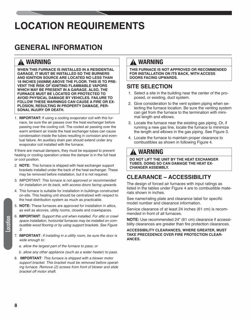
6. IMPORTANT: Support this unit when installed. For attic or crawlspace installation, horizontal furnaces may be installed on com-bustible wood flooring or by using support brackets. See Figure3.
7. IMPORTANT: If installing in a utility room, be sure the door iswide enough to:
a. allow the largest part of the furnace to pass; or b. allow any other appliance (such as a water heater) to pass.8. IMPORTANT: This furnace is shipped with a blower motor
support bracket. This bracket must be removed before operat-ing furnace. Remove (2) screws from front of blower and slidebracket off motor shaft.
SITE SELECTION 1. Select a site in the building near the center of the pro-
posed, or existing, duct system. 2. Give consideration to the vent system piping when se-
lecting the furnace location. Be sure the venting systemcan get from the furnace to the termination with mini-mal length and elbows.
3. Locate the furnace near the existing gas piping. Or, ifrunning a new gas line, locate the furnace to minimizethe length and elbows in the gas piping. See Figure 3.
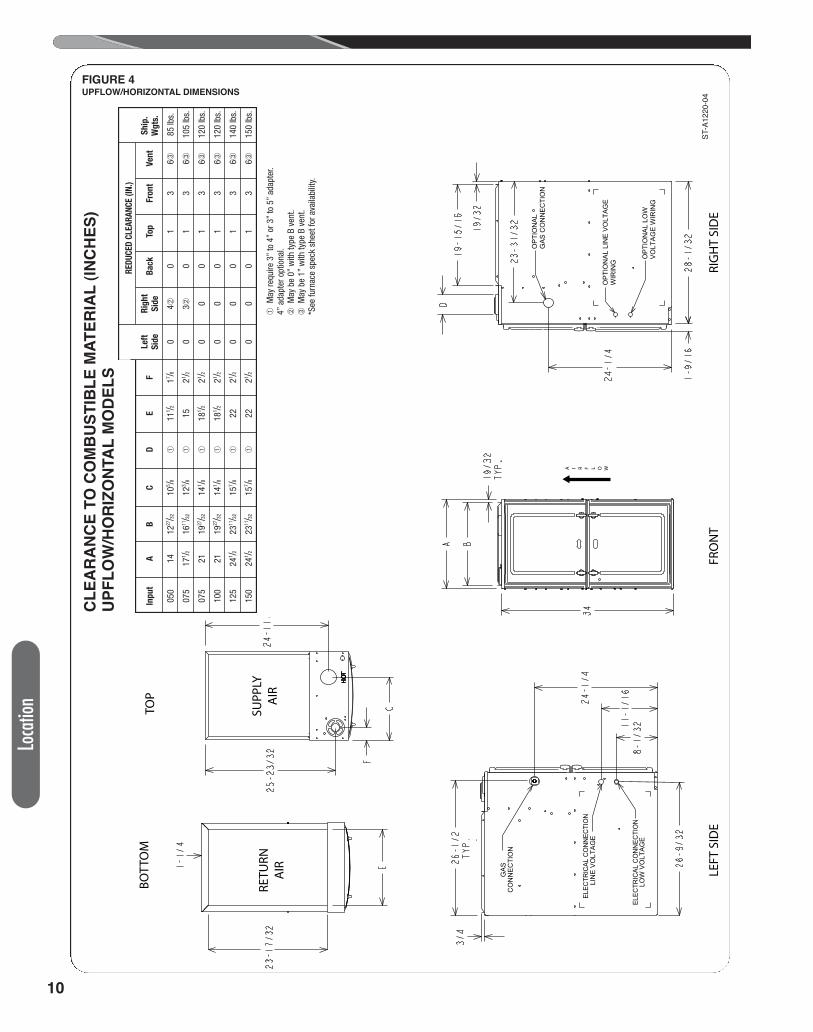
4. Locate the furnace to maintain proper clearance tocombustibles as shown in following Figure 4.
CLEARANCE – ACCESSIBILITYThe design of forced air furnaces with input ratings aslisted in the tables under Figure 4 are to combustible mate-rials shown in inches.See name/rating plate and clearance label for specificmodel number and clearance information.Service clearance of at least 24 inches (61 cm) is recom-mended in front of all furnaces.NOTE: Use recommended 24” (61 cm) clearance if accessi-bility clearances are greater than fire protection clearances.ACCESSIBILITY CLEARANCES, WHERE GREATER, MUST
TAKE PRECEDENCE OVER FIRE PROTECTION CLEAR-
ANCES.
GENERAL INFORMATION
LOCATION REQUIREMENTS
Loca
tion
! WARNINGWHEN THIS FURNACE IS INSTALLED IN A RESIDENTIALGARAGE, IT MUST BE INSTALLED SO THE BURNERSAND IGNITION SOURCE ARE LOCATED NO LESS THAN18 INCHES [450MM] ABOVE THE FLOOR. THIS IS TO PRE-VENT THE RISK OF IGNITING FLAMMABLE VAPORSWHICH MAY BE PRESENT IN A GARAGE. ALSO, THEFURNACE MUST BE LOCATED OR PROTECTED TOAVOID PHYSICAL DAMAGE BY VEHICLES. FAILURE TOFOLLOW THESE WARNINGS CAN CAUSE A FIRE OR EX-PLOSION, RESULTING IN PROPERTY DAMAGE, PER-SONAL INJURY OR DEATH.
! WARNINGTHIS FURNACE IS NOT APPROVED OR RECOMMENDEDFOR INSTALLATION ON ITS BACK, WITH ACCESSDOORS FACING UPWARDS.
! WARNINGDO NOT LIFT THE UNIT BY THE HEAT EXCHANGERTUBES. DOING SO CAN DAMAGE THE HEAT EX-CHANGER ASSEMBLY.
9
Location
GENERAL INFORMATION (cont.)
LOCATION REQUIREMENTS
NOTE:HORIZONTAL LEFT ORIENTATION DEPICTED IN ILLUSTRATION. HORIZONTAL RIGHT ORIENTATION IS SIMILAR IN INSTALLATION.
AIR FLOW ST-A1220-03
FIGURE 3
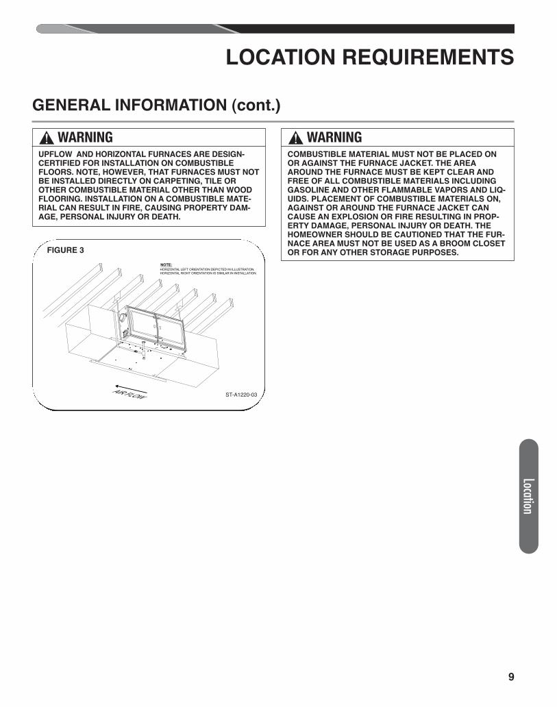
! WARNINGCOMBUSTIBLE MATERIAL MUST NOT BE PLACED ONOR AGAINST THE FURNACE JACKET. THE AREAAROUND THE FURNACE MUST BE KEPT CLEAR ANDFREE OF ALL COMBUSTIBLE MATERIALS INCLUDINGGASOLINE AND OTHER FLAMMABLE VAPORS AND LIQ-UIDS. PLACEMENT OF COMBUSTIBLE MATERIALS ON,AGAINST OR AROUND THE FURNACE JACKET CANCAUSE AN EXPLOSION OR FIRE RESULTING IN PROP-ERTY DAMAGE, PERSONAL INJURY OR DEATH. THEHOMEOWNER SHOULD BE CAUTIONED THAT THE FUR-NACE AREA MUST NOT BE USED AS A BROOM CLOSETOR FOR ANY OTHER STORAGE PURPOSES.
! WARNINGUPFLOW AND HORIZONTAL FURNACES ARE DESIGN-CERTIFIED FOR INSTALLATION ON COMBUSTIBLEFLOORS. NOTE, HOWEVER, THAT FURNACES MUST NOTBE INSTALLED DIRECTLY ON CARPETING, TILE OROTHER COMBUSTIBLE MATERIAL OTHER THAN WOODFLOORING. INSTALLATION ON A COMBUSTIBLE MATE-RIAL CAN RESULT IN FIRE, CAUSING PROPERTY DAM-AGE, PERSONAL INJURY OR DEATH.
10
BOTT
OM
TOP
LEFT
SID
EFR
ON
TRI
GH
T SI
DE
GAS
CO
NNECTIO
N
ELEC
TRICAL
CO
NNEC
TIO
NLI
NE
VO
LTAGE
ELEC
TRICAL
CO
NNEC
TIO
NLO
W VO
LTAGE
OPTIO
NA
L GAS
CO
NNECTIO
N
OPTIO
NA
L LO
W
VO
LTAGE
WIR
ING
OPTIO
NA
L LI
NE
VO
LTAGE
WIR
ING
A I R F L O W
RETU
RNA
IR
SUPP
LYA
IR
HO
T
MO
DEL
AB
CD
EF
RIG
HT S
IDE
BACK
TOP
FRO
NT
VEN
T5
1413
27/
3210
5/8
11 1
/21
7/8
04
01
36
85 lb
s.7
17 1
/216
11/
3212
3/8
152
1/2
03
01
36
105
lbs.
1021
19 2
7/32
14 1
/818
1/2
2 1/
20
00
13
612
0 lb
s.12
24 1
/223
11/
3215
7/8
222
1/2
00
01
36
140
lbs.
1524
1/2
23 1
1/32
15 7
/822
2 1/
20
00
13
615
0 lb
s.M
AY R
EQU
IRE
3" T
O 4
" OR
3" T
O 5
" ADA
PTER
.4"
ADA
PTER
INCL
UDE
D W
ITH
(-)80
1P U
NIT
S.M
AY B
E 0"
WIT
H TY
PE B
VEN
T.M
AY B
E 1"
WIT
H TY
PE B
VEN
T.
LEFT
SID
ERE
DUCE
D CL
EARA
NCE
(IN
.)SH
IP
WGT
S.
FIGURE 4UPFLOW/HORIZONTAL DIMENSIONS
Loca
tion
R
EDUC
ED C
LEAR
ANCE
(IN.
)
In
put
A
B
C
D
E
F
Left
Ri
ght
Back
Top
F
ront
Ven
t
Shi
p.
Sid
e
Side
Wgt
s.
05
0
14
1227
/32
1
05 /8
¿
111 /2
17 /8
0
4¡
0
1
3
6¬
85
lbs.
0
75
171 /2
1611/32
123 /8
¿
15
21 /2
0
3¡
0
1
3
6¬
105
lbs.
0
75
21
19
27/32
141 /8
¿
1
81 /2
21 /2
0
0
0
1
3
6¬
120
lbs.
1
00
21
19
27/32
141 /8
¿
1
81 /2
21 /2
0
0
0
1
3
6¬
120
lbs.
1
25
241 /2
2311/32
157 /8
¿
22
21 /2
0
0
0
1
3
6¬
140
lbs.
1
50
241 /2
2311/32
157 /8
¿
22
21 /2
0
0
0
1
3
6¬
150
lbs.
CL
EA
RA
NC
E T
O C
OM
BU
ST
IBL
E M
AT
ER
IAL
(IN
CH
ES
)U
PF
LO
W/H
OR
IZO
NTA
L M
OD
EL
S
¿ M
ay re
quire
3”
to 4
” or
3”
to 5
” ad
apte
r.4”
ada
pter
opt
iona
l.¡
May
be
0” w
ith ty
pe B
ven
t.¬
May
be
1” w
ith ty
pe B
ven
t.*S
ee fu
rnac
e sp
eck
shee
t for
ava
ilabi
lity.
ST-A
1220
-04
11
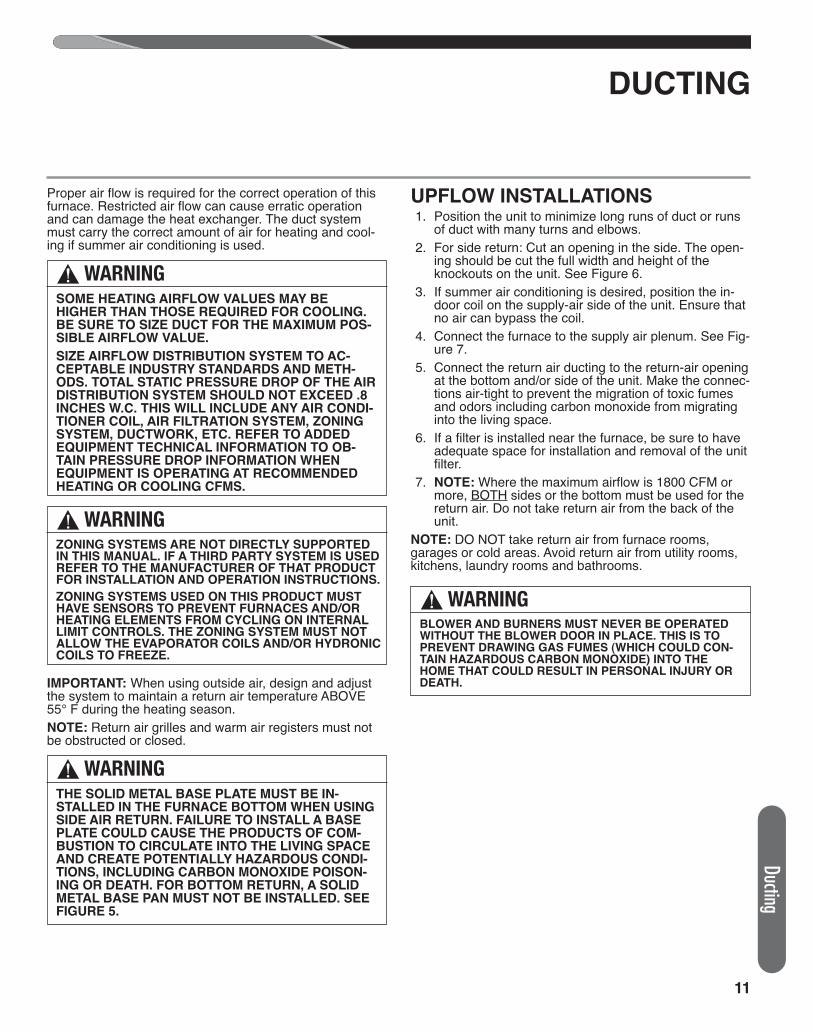
Proper air flow is required for the correct operation of thisfurnace. Restricted air flow can cause erratic operationand can damage the heat exchanger. The duct systemmust carry the correct amount of air for heating and cool-ing if summer air conditioning is used.
IMPORTANT: When using outside air, design and adjustthe system to maintain a return air temperature ABOVE55° F during the heating season.NOTE: Return air grilles and warm air registers must notbe obstructed or closed.
UPFLOW INSTALLATIONS 1. Position the unit to minimize long runs of duct or runs
of duct with many turns and elbows. 2. For side return: Cut an opening in the side. The open-
ing should be cut the full width and height of theknockouts on the unit. See Figure 6.
3. If summer air conditioning is desired, position the in-door coil on the supply-air side of the unit. Ensure thatno air can bypass the coil.
4. Connect the furnace to the supply air plenum. See Fig-ure 7.
5. Connect the return air ducting to the return-air openingat the bottom and/or side of the unit. Make the connec-tions air-tight to prevent the migration of toxic fumesand odors including carbon monoxide from migratinginto the living space.
6. If a filter is installed near the furnace, be sure to haveadequate space for installation and removal of the unitfilter.
7. NOTE: Where the maximum airflow is 1800 CFM ormore, BOTH sides or the bottom must be used for thereturn air. Do not take return air from the back of theunit.
NOTE: DO NOT take return air from furnace rooms,garages or cold areas. Avoid return air from utility rooms,kitchens, laundry rooms and bathrooms.
DUCTING
Ducting
! WARNINGBLOWER AND BURNERS MUST NEVER BE OPERATEDWITHOUT THE BLOWER DOOR IN PLACE. THIS IS TOPREVENT DRAWING GAS FUMES (WHICH COULD CON-TAIN HAZARDOUS CARBON MONOXIDE) INTO THEHOME THAT COULD RESULT IN PERSONAL INJURY ORDEATH.
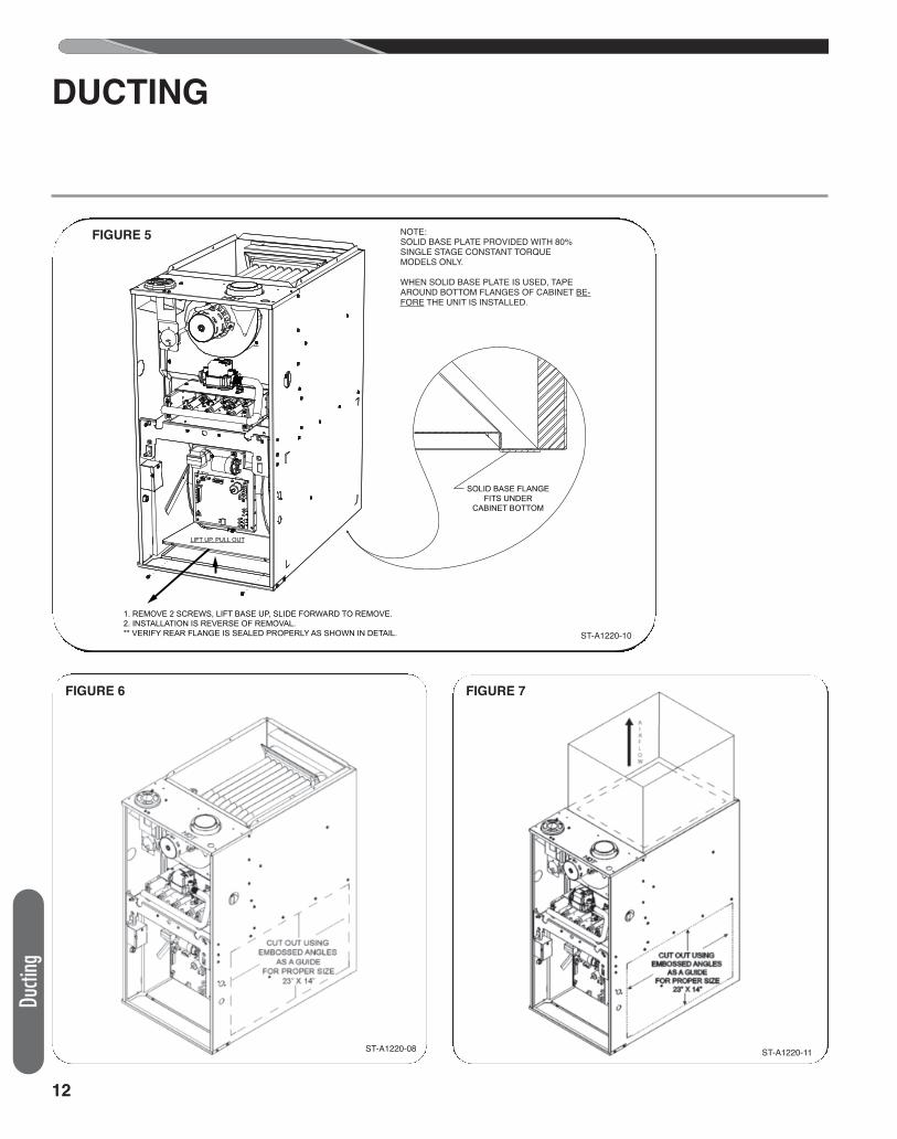
! WARNINGTHE SOLID METAL BASE PLATE MUST BE IN-STALLED IN THE FURNACE BOTTOM WHEN USINGSIDE AIR RETURN. FAILURE TO INSTALL A BASEPLATE COULD CAUSE THE PRODUCTS OF COM-BUSTION TO CIRCULATE INTO THE LIVING SPACEAND CREATE POTENTIAL LY HAZARDOUS CONDI-TIONS, INCLUDING CARBON MONOXIDE POISON-ING OR DEATH. FOR BOTTOM RETURN, A SOLIDMETAL BASE PAN MUST NOT BE INSTALLED. SEEFIGURE 5.
! WARNINGSOME HEATING AIRFLOW VALUES MAY BEHIGHER THAN THOSE REQUIRED FOR COOLING.BE SURE TO SIZE DUCT FOR THE MAXIMUM POS-SIBLE AIRFLOW VALUE.
SIZE AIRFLOW DISTRIBUTION SYSTEM TO AC-CEPTABLE INDUSTRY STANDARDS AND METH-ODS. TOTAL STATIC PRESSURE DROP OF THE AIRDISTRIBUTION SYSTEM SHOULD NOT EXCEED .8INCHES W.C. THIS WILL INCLUDE ANY AIR CONDI-TIONER COIL, AIR FILTRATION SYSTEM, ZONINGSYSTEM, DUCTWORK, ETC. REFER TO ADDEDEQUIPMENT TECHNICAL INFORMATION TO OB-TAIN PRESSURE DROP INFORMATION WHENEQUIPMENT IS OPERATING AT RECOMMENDEDHEATING OR COOLING CFMS.
! WARNINGZONING SYSTEMS ARE NOT DIRECTLY SUPPORTEDIN THIS MANUAL. IF A THIRD PARTY SYSTEM IS USEDREFER TO THE MANUFACTURER OF THAT PRODUCTFOR INSTALLATION AND OPERATION INSTRUCTIONS.
ZONING SYSTEMS USED ON THIS PRODUCT MUSTHAVE SENSORS TO PREVENT FURNACES AND/ORHEATING ELEMENTS FROM CYCLING ON INTERNALLIMIT CONTROLS. THE ZONING SYSTEM MUST NOTALLOW THE EVAPORATOR COILS AND/OR HYDRONICCOILS TO FREEZE.
12
Ducti
ng
DUCTING
FIGURE 5 NOTE:SOLID BASE PLATE PROVIDED WITH (-)801PMODELS ONLY.
WHEN SOLID BASE PLATE IS USED . TAPE AROUND BOTTOM FLANGES OF CABINET BEFORE THE UNIT IS INSTALLED.
LIFT UP, PULL OUT
1. REMOVE 2 SCREWS, LIFT BASE UP, SLIDE FORWARD TO REMOVE.2. INSTALLATION IS REVERSE OF REMOVAL.** VERIFY REAR FLANGE IS SEALED PROPERLY AS SHOWN IN DETAIL. ST-A1220-10-X0
SOLID BASE FLANGE FITS UNDER
CABINET BOTTOM
FIGURE 6 FIGURE 7
ST-A1220-10
ST-A1220-11ST-A1220-08
NOTE:SOLID BASE PLATE PROVIDED WITH 80% SINGLE STAGE CONSTANT TORQUE MODELS ONLY.
WHEN SOLID BASE PLATE IS USED, TAPEAROUND BOTTOM FLANGES OF CABINET BE-FORE THE UNIT IS INSTALLED.
13
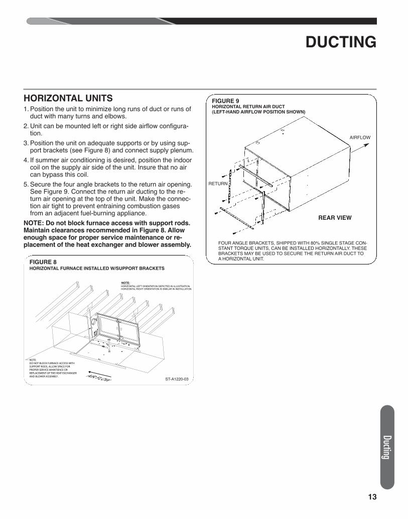
HORIZONTAL UNITS1. Position the unit to minimize long runs of duct or runs of
duct with many turns and elbows. 2. Unit can be mounted left or right side airflow configura-
tion.3. Position the unit on adequate supports or by using sup-
port brackets (see Figure 8) and connect supply plenum.4. If summer air conditioning is desired, position the indoor
coil on the supply air side of the unit. Insure that no aircan bypass this coil.
5. Secure the four angle brackets to the return air opening.See Figure 9. Connect the return air ducting to the re-turn air opening at the top of the unit. Make the connec-tion air tight to prevent entraining combustion gasesfrom an adjacent fuel-burning appliance.
NOTE: Do not block furnace access with support rods.Maintain clearances recommended in Figure 8. Allowenough space for proper service maintenance or re-placement of the heat exchanger and blower assembly.
DUCTING
FOUR ANGLE BRACKETS, SHIPPED WITH 80% SINGLE STAGE CON-STANT TORQUE UNITS, CAN BE INSTALLED HORIZONTALLY. THESEBRACKETS MAY BE USED TO SECURE THE RETURN AIR DUCT TOA HORIZONTAL UNIT.
RETURN
AIRFLOW
REAR VIEW
FIGURE 9HORIZONTAL RETURN AIR DUCT(LEFT-HAND AIRFLOW POSITION SHOWN)
NOTE:HORIZONTAL LEFT ORIENTATION DEPICTED IN ILLUSTRATION. HORIZONTAL RIGHT ORIENTATION IS SIMILAR IN INSTALLATION.
AIR FLOW
NOTE:DO NOT BLOCK FURNACE ACCESS WITH SUPPORT RODS, ALLOW SPACE FOR PROPER SERVICE MAINTIENCE OR REPLACEMENT OF THE HEAT EXCHANGER AND BLOWER ASSEMBLY .
FIGURE 8HORIZONTAL FURNACE INSTALLED W/SUPPORT BRACKETS
ST-A1220-03
Ducting
14
Comb
ustio
n Air
COMBUSTION AND VENTILATION AIR
1. IMPORTANT: Air for combustion and ventilation must notcome from a corrosive atmosphere. Any failure due to corro-sive elements in the atmosphere is excluded from warrantycoverage.
2. Combustion air must be free of acid forming chemicals; suchas sulphur, fluorine and chlorine. These elements are found inaerosol sprays, detergents, bleaches, cleaning solvents, airfresheners, paint and varnish removers, refrigerants and manyother commercial and household products. Vapors from theseproducts when burned in a gas flame form acid compounds.The acid compounds increase the dew point temperature ofthe flue products and are highly corrosive after they condense.
3. The following types of installation may require OUTDOOR AIRfor combustion, due to chemical exposures:• Commercial buildings• Buildings with indoor pools• Furnaces installed in laundry rooms• Furnaces in hobby or craft rooms• Furnaces installed near chemical storage areas.
4. If combustion air is exposed to the following substances (butnot limited to the following), it should not be used and the fur-nace may require outdoor air for combustion.• Permanent wave solutions• Chlorinated waxes and cleaners• Chlorine-based swimming pool chemicals• Water softening chemicals• De-icing salts or chemicals• Carbon tetrachloride
• Halogen type refrigerants• Cleaning solvents (such as perchloroethylene)• Printing inks, paint removers, varnishes, etc.• Hydrochloric acid• Cements and glues• Antistatic fabric softeners for clothes dryers• Masonry curing and acid washing materials
Combustion air requirements are determined by whether the fur-nace is in an open (unconfined) area or in a confined space suchas a closet or small room.When the furnace is installed in the same space with other gas ap-pliances, such as a water heater, be sure there is an adequatesupply of combustion and ventilation air for the furnace and theother appliances. Do not delete or reduce the combustion air sup-ply required by the other gas appliances in this space. See Z223.1,National Fuel Gas Code (NFPA 54). An unconfined space musthave at least 50 cubic feet (volume) for each 1,000 BTUH of thetotal input of all appliances in the space. If the open space contain-ing the appliances is in a building with tight construction (contem-porary construction), outside air may still be required for theappliances to burn and vent properly. Outside air openings shouldbe sized the same as for a confined space.IMPORTANT: ONLY THE CURRENT VENT INSTRUCTIONSAPPLY. All gas furnaces cannot be common-vented.
OVERTEMPERATURE SAFETYSWITCHESFurnaces are equipped with safety switches in the burner com-partment to protect against over-temperature conditions causedby inadequate combustion air supply. The switches are locatedin the burner compartment. If a switch is tripped it must be manu-ally reset after clearing the fault condition which caused it toopen.
IMPORTANT: This is not a direct vent furnace. Review ventinginstructions before installing.
! WARNINGTHIS FURNACE AND ANY OTHER FUEL-BURNING APPLI-ANCE MUST BE PROVIDED WITH ENOUGH FRESH AIRFOR PROPER COMBUSTION AND VENTILATION OF THEFLUE GASES. MOST HOMES WILL REQUIRE THAT OUT-SIDE AIR BE SUPPLIED INTO THE FURNACE AREA.FAILURE TO DO SO CAN CAUSE DEATH FROM CARBONMONOXIDE POISONING.
! WARNINGADEQUATE FACILITIES FOR PROVIDING AIR FOR COM-BUSTION AND VENTILATION MUST BE PROVIDED IN AC-CORDANCE WITH SECTION 5.3, AIR FOR COMBUSTIONAND VENTILATION, OF THE NATIONAL FUEL GAS CODE,ANSI, Z223.1 LATEST EDITION OR APPLICABLE PROVI-SIONS FOR THE LOCAL BUILDING CODES, AND NOTOBSTRUCTED SO AS TO PREVENT THE FLOW OF AIRTO THE FURNACE.
COMBUSTION AIR REQUIREMENTS
! WARNINGALL FURNACE INSTALLATIONS MUST COMPLY WITHTHE NATIONAL FUEL GAS CODE AND LOCAL CODES TOPROVIDE ADEQUATE COMBUSTION AND VENTILATIONAIR FOR THE FURNACE. FAILURE TO DO SO CAN CRE-ATE HAZARDOUS CONDITIONS RESULTING IN PROP-ERTY DAMAGE, BODILY INJURY OR DEATH FROMSMOKE, FIRE OR CARBON MONOXIDE.
! WARNINGDO NOT BYPASS, JUMPER, OR REMOVE ANY SAFETYSWITCH FROM THE FURNACE CONTROL CIRCUIT. IF ASAFETY SWITCH CAUSES THE FURNACE TO SHUTDOWN OR OPERATE INTERMITTENTLY, IT IS AN INDICA-TION OF A POTENTIAL SAFETY HAZARD THAT MUST BEADDRESSED BY A QUALIFIED TECHNICIAN, SERVICEAGENCY OR THE GAS SUPPLIER. DO NOT RESETSAFETY CONTROLS WITHOUT CORRECTIVE ACTIONAND/OR VERIFICATION OF PROPER SAFE OPERATIONBY A QUALIFIED INSTALLER, SERVICE AGENCY OR THEGAS SUPPLIER.
REPLACE ANY SAFETY CONTROL COMPONENT WITHIDENTICAL OEM REPLACEMENT PARTS ONLY.
15
COMBUSTION AND VENTILATION AIR (cont.)
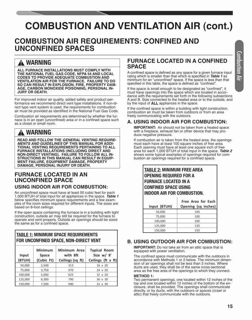
For improved indoor air quality, added safety and product per-formance we recommend direct vent type installations. If non-di-rect type vent system is used, the requirements for combustionair must be provided as identified in the National Fuel Gas Code.Combustion air requirements are determined by whether the fur-nace is in an open (unconfined) area or in a confined space suchas a closet or small room.
FURNACE LOCATED IN AN UNCONFINED SPACEUSING INDOOR AIR FOR COMBUSTION:An unconfined space must have at least 50 cubic feet for each1,000 BTUH of total input for all appliances in the space. Table 1below specifies minimum space requirements and a few exam-ples of the room sizes required for different inputs. The sizes arebased on 8-foot ceilings.If the open space containing the furnace is in a building with tightconstruction, outside air may still be required for the furnace tooperate and vent properly. Outside air openings should be sizedthe same as for a confined space.
FURNACE LOCATED IN A CONFINEDSPACEA confined space is defined as any space for a given furnace inputrating which is smaller than that which is specified in Table 1 asminimum for an “unconfined” space. If the space is less than thatspecified in this table, the space is defined as “confined”.If the space is small enough to be designated as “confined”, itmust have openings into the space which are located in accor-dance with the requirements set forth in the following subsectionsA and B. Size connected to the heated area or to the outside, andby the input of ALL appliances in the space.If the confined space is within a building with tight construction,combustion air must be taken from outdoors or from an areafreely communicating with the outdoors.A. USING INDOOR AIR FOR COMBUSTION:
IMPORTANT: Air should not be taken from a heated spacewith a fireplace, exhaust fan or other device that may pro-duce negative pressure.If combustion air is taken from the heated area, the openingsmust each have at least 100 square inches of free area.Each opening must have at least one square inch of freearea for each 1,000 BTUH of total input in the space. Table 2shows some typical examples of openings required for com-bustion air openings required for a confined space.
B. USING OUTDOOR AIR FOR COMBUSTION:IMPORTANT: Do not take air from an attic space that isequipped with power ventilation.The confined space must communicate with the outdoors inaccordance with Methods 1 or 2 below. The minimum dimen-sion of air openings shall not be less than 3 inches. Whereducts are used, they shall be of the same cross-sectionalarea as the free area of the openings to which they connect.METHOD 1:Two permanent openings, one located within 12 inches of thetop and one located within 12 inches of the bottom of the en-closure, shall be provided. The openings shall communicate directly, or by ducts, with the outdoors or spaces (crawl or attic) that freely communicate with the outdoors.
Combustion Air
COMBUSTION AIR REQUIREMENTS: CONFINED AND UNCONFINED SPACES
! WARNINGALL FURNACE INSTALLATIONS MUST COMPLY WITHTHE NATIONAL FUEL GAS CODE, NFPA 54 AND LOCALCODES TO PROVIDE ADEQUATE COMBUSTION ANDVENTILATION AIR FOR THE FURNACE. FAILURE TO DOSO CAN RESULT IN EXPLOSION, FIRE, PROPERTY DAM-AGE, CARBON MONOXIDE POISONING, PERSONAL IN-JURY OR DEATH.
! WARNINGREAD AND FOLLOW THE GENERAL VENTING REQUIRE-MENTS AND GUIDELINES OF THIS MANUAL FOR ADDI-TIONAL VENTING REQUIREMENTS PERTAINING TO ALLFURNACE INSTALLATIONS (INCLUDING DIRECT ANDNON-DIRECT VENTING). FAILURE TO FOLLOW ALL IN-STRUCTIONS IN THIS MANUAL CAN RESULT IN EQUIP-MENT FAILURE, EQUIPMENT DAMAGE, PROPERTYDAMAGE, PERSONAL INJURY OR DEATH.
TABLE 7: MINIMUM SPACE REQUIREMENTS FOR UNCONFINED SPACE, NON-DIRECT VENT*
Input (BTUH)
Minimum Space
(Cubic Ft)
Minimum Area with 8�
Ceilings (sq �)
Typical Room Size w/ 8'
Ceilings (� x �) 50,000 2,500 313 16 x 20 75,000 3,750 470 24 x 20 100,000 5,000 625 32 x 20 125,000 6,300 790 36 x 30 150,000 7,500 940 32 x 30
TABLE 1: MINIMUM SPACE REQUIREMENTSFOR UNCONFINED SPACE, NON-DIRECT VENT
TABLE 8: MINIMUM FREE AREA OPENING REQUIRED FOR A FURNACE LOCATED IN A CONFINED SPACE USING INDOOR AIR FOR COMBUSTION.
Input (BTUH) Free Area for Each
Opening (sq inches) 50,000 100 75,000 100 100,000 100 125,000 130 150,000 150
TABLE 2: MINIMUM FREE AREAOPENING REQUIRED FOR AFURNACE LOCATED IN ACONFINED SPACE USINGINDOOR AIR FOR COMBUSTION.
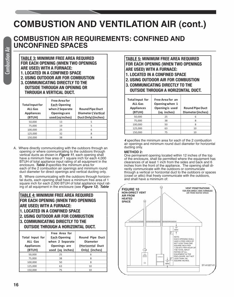
A. Where directly communicating with the outdoors through anopening or where communicating to the outdoors throughvertical ducts as shown in Figure 11, each opening shallhave a minimum free area of 1 square inch for each 4,000BTUH of total appliance input rating of all equipment in theenclosure. Table 3 specifies the minimum area for each of the 2 combustion air openings and minimum roundduct diameter for direct openings and vertical ducting only.B. Where communicating with the outdoors through horizon-tal ducts, each opening shall have a minimum free area of 1square inch for each 2,000 BTUH of total appliance input rat-ing of all equipment in the enclosure (see Figure 12). Table
4 specifies the minimum area for each of the 2 combustionair openings and minimum round duct diameter for horizontalducting only.METHOD 2:One permanent opening located within 12 inches of the topof the enclosure, shall be permitted where the equipment hasclearances of at least 1 inch from the sides and back and 6inches from the front of the appliance. The opening shall di-rectly communicate with the outdoors or communicatethrough a vertical or horizontal duct to the outdoors or spaces(crawl or attic) that freely communicate with the outdoors,and shall have a minimum of:
TABLE 9 : MINIMUM FREE AREA REQUIRED FOR EACH OPENING (WHEN TWO OPENINGS ARE USED) WITH A FURNACE: 1. LOCATED IN A CONFINED SPACE 2. USING OUTDOOR AIR FOR COMBUSTION 3. COMMUNICATING DIRECTLY TO THE
OUTSIDE THROUGH AN OPENING OR THROUGH A VERTICAL VENT DUCT.*
Total Input for ALL Gas
Appliances (BTUH)
Free Area for Each Opening
when 2 Separate Openings are
used (sq inches)
Round Pipe Duct Diameter ( Ver�cal Duct Only) (inches)
50,000 13 5 75,000 19 5 100,000 25 6 125,000 32 8 150,000 38 8
TABLE 3: MINIMUM FREE AREA REQUIREDFOR EACH OPENING (WHEN TWO OPENINGSARE USED) WITH A FURNACE:1. LOCATED IN A CONFINED SPACE2. USING OUTDOOR AIR FOR COMBUSTION3. COMMUNICATING DIRECTLY TO THE3. OUTSIDE THROUGH AN OPENING OR3. THROUGH A VERTICAL DUCT.
16
Comb
ustio
n Air
COMBUSTION AND VENTILATION AIR (cont.)
TABLE 1 0: MINIMUM FREE AREA REQUIRED FOR EACH OPENING (WHEN TWO OPENINGS ARE USED) WITH A FURNACE: 1. LOCATED IN A CONFINED SPACE 2. USING OUTDOOR AIR FOR COMBUSTION 3. COMMUNICATING DIRECTLY TO THE
OUTSIDE THROUGH A H ORIZONTAL DUCT.
Total Input for ALL Gas
Appliances (BTUH)
Free Area for Each Opening
when 2 Separate Openings are
used (sq inches)
Round Pipe Duct Diameter
(Horizontal Duct Only) (inches)
50,000 25 6 75,000 38 8 100,000 50 8 125,000 63 10 150,000 75 10
TABLE 4: MINIMUM FREE AREA REQUIREDFOR EACH OPENING (WHEN TWO OPENINGSARE USED) WITH A FURNACE:1. LOCATED IN A CONFINED SPACE2. USING OUTDOOR AIR FOR COMBUSTION3. COMMUNICATING DIRECTLY TO THE3. OUTSIDE THROUGH A HORIZONTAL DUCT.
TABLE 1 1: MINIMUM FREE AREA REQUIRED FOR AN OPENING (WHEN O N E OPENING IS USED) WITH A FURNACE: 1. LOCATED IN A CONFINED SPACE 2. USING OUTDOOR AIR FOR COMBUSTION 3. COMMUNICATING DIRECTLY TO THE
*
Total Input for ALL Gas
Appliances (BTUH)
Free Area for an Opening when 1 Opening is used
(sq inches) Round Pipe Duct
Diameter (inches) 50,000 25 6 75,000 38 8 100,000 50 8 125,000 63 10 150,000 75 10
OUTSIDE.
TABLE 5: MINIMUM FREE AREA REQUIREDFOR EACH OPENING (WHEN TWO OPENINGSARE USED) WITH A FURNACE:1. LOCATED IN A CONFINED SPACE2. USING OUTDOOR AIR FOR COMBUSTION3. COMMUNICATING DIRECTLY TO THE3. OUTSIDE THROUGH A HORIZONTAL DUCT.
COMBUSTION AIR REQUIREMENTS: CONFINED AND UNCONFINED SPACES
GAS
WATER
HEATER FURNACE
12”
MAX
12”
MAX
NOTE:
EACH OPENING SHALL
HAVE A FREE AREA OF
NOT LESS THAN ONE
SQUARE INCH PER
1,000 BTU PER HOUR OF
THE TOTAL INPUT
RATING OF ALL
EQUIPMENT IN THE
ENCLOSURE, BUT NOT
LESS THAN 100
SQUARE INCHES.
ST-A1227-01
FIGURE 10NON-DIRECT VENTAIR FROM HEATED SPACE
VENT PENETRATIONSFOR NON DIRECT VENT FURNACES
AIR FROM HEATED SPACE
17
COMBUSTION AND VENTILATION AIR (cont.)
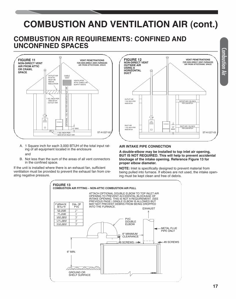
A. 1 Square inch for each 3,000 BTUH of the total input rat-ing of all equipment located in the enclosure and
B. Not less than the sum of the areas of all vent connectorsin the confined space.
If the unit is installed where there is an exhaust fan, sufficientventilation must be provided to prevent the exhaust fan from cre-ating negative pressure.
AIR INTAKE PIPE CONNECTION
A double-elbow may be installed to top inlet air opening,BUT IS NOT REQUIRED. This will help to prevent accidentalblockage of the intake opening. Reference Figure 13 forproper elbow diameter.
NOTE: Inlet is specifically designed to prevent material frombeing pulled into furnace. If elbows are not used, the intake open-ing must be kept clean and free of debris.
ATTACH OPTIONAL DOUBLE ELBOW TO TOP INLET AIROPENING TO PREVENT ACCIDENTAL BLOCKAGE OFINTAKE OPENING. THIS IS NOT A REQUIREMENT. (SEEPREVIOUS PAGE.) SINGLE ELBOW IS ALLOWED BUTMAY NOT PREVENT DEBRIS FROM BEING DROPPEDINTO THE FURNACE.
GROUND ORSHELF SURFACE
6" MIN.
6" MINIMUMCLEARANCE
PVCDOUBLEELBOW
#8 SCREWS
METAL FLUEPIPE ONLY
EXHAUST
#8 SCREWS
FIGURE 13COMBUSTION AIR FITTING – NON-ATTIC COMBUSTION AIR PULL
Combustion Air
GASWATERHEATER FURNACE
OP
TIO
NA
L 1
SQ
. IN
CH
PE
R 4
000
BTU
H IN
LET
AIR
GABLEVENT
VENTILATEDATTIC GABLE ORSOFFIT VENTS
OUTLET AIRIN ATTICMUST BEABOVEINSULATION
1 SQ. INCH PER4000 BTUH INLET AIR
12” MAX
1 SQ. INCH PER4000 BTUH
OUTLET AIR
GASWATERHEATER FURNACE
12”MAX
INLET AIR 1 SQ. INCHPER 2000 BTUH
OUTLET AIR 1 SQ. INCHPER 2000 BTUH
OUTLET AIR1 SQ. INCH PER4000 BTUH
INLET AIR1 SQ. INCH PER4000 BTUH
ST-A1227-03ST-A1227-02
FIGURE 11NON-DIRECT VENTAIR FROM ATTICOR CRAWLSPACE
FIGURE 12NON-DIRECT VENT OUTSIDE AIR USING AHORIZONTAL DUCT
COMBUSTION AIR REQUIREMENTS: CONFINED AND UNCONFINED SPACES
VENT PENETRATIONSFOR NON DIRECT VENT FURNACES
AIR FROM ATTIC/CRAWL SPACE
VENT PENETRATIONSFOR NON DIRECT VENT FURNACES
AIR FROM ATTIC/CRAWL SPACE
Comb
ustio
n Air
18
COMBUSTION AND VENTILATION AIR (cont.)
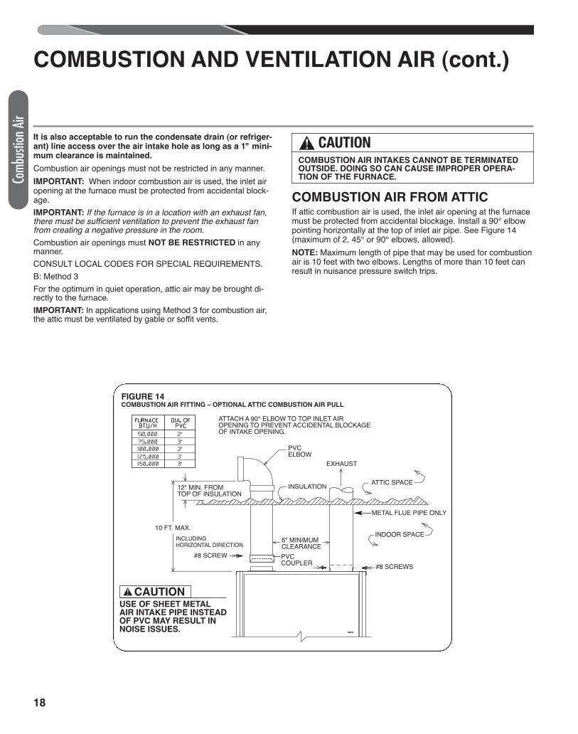
It is also acceptable to run the condensate drain (or refriger-ant) line access over the air intake hole as long as a 1" mini-mum clearance is maintained.
Combustion air openings must not be restricted in any manner.IMPORTANT: When indoor combustion air is used, the inlet airopening at the furnace must be protected from accidental block-age.IMPORTANT: If the furnace is in a location with an exhaust fan,there must be sufficient ventilation to prevent the exhaust fanfrom creating a negative pressure in the room.Combustion air openings must NOT BE RESTRICTED in anymanner.CONSULT LOCAL CODES FOR SPECIAL REQUIREMENTS.B: Method 3For the optimum in quiet operation, attic air may be brought di-rectly to the furnace.IMPORTANT: In applications using Method 3 for combustion air,the attic must be ventilated by gable or soffit vents.
COMBUSTION AIR FROM ATTICIf attic combustion air is used, the inlet air opening at the furnacemust be protected from accidental blockage. Install a 90° elbowpointing horizontally at the top of inlet air pipe. See Figure 14(maximum of 2, 45° or 90° elbows, allowed).NOTE: Maximum length of pipe that may be used for combustionair is 10 feet with two elbows. Lengths of more than 10 feet canresult in nuisance pressure switch trips.
! CAUTIONCOMBUSTION AIR INTAKES CANNOT BE TERMINATEDOUTSIDE. DOING SO CAN CAUSE IMPROPER OPERA-TION OF THE FURNACE.
INCLUDINGHORIZONTAL DIRECTION
ATTACH A 90° ELBOW TO TOP INLET AIROPENING TO PREVENT ACCIDENTAL BLOCKAGEOF INTAKE OPENING.
CAUTION!
PVCELBOW
#8 SCREWS#8 SCREW
METAL FLUE PIPE ONLY
10 FT. MAX.
12" MIN. FROMTOP OF INSULATION
6" MINIMUMCLEARANCEPVCCOUPLER
EXHAUST
ATTIC SPACE
INDOOR SPACE
INSULATION
USE OF SHEET METALAIR INTAKE PIPE INSTEADOF PVC MAY RESULT INNOISE ISSUES.
FIGURE 14COMBUSTION AIR FITTING – OPTIONAL ATTIC COMBUSTION AIR PULL
19
COMBUSTION AND VENTILATION AIR (cont.)
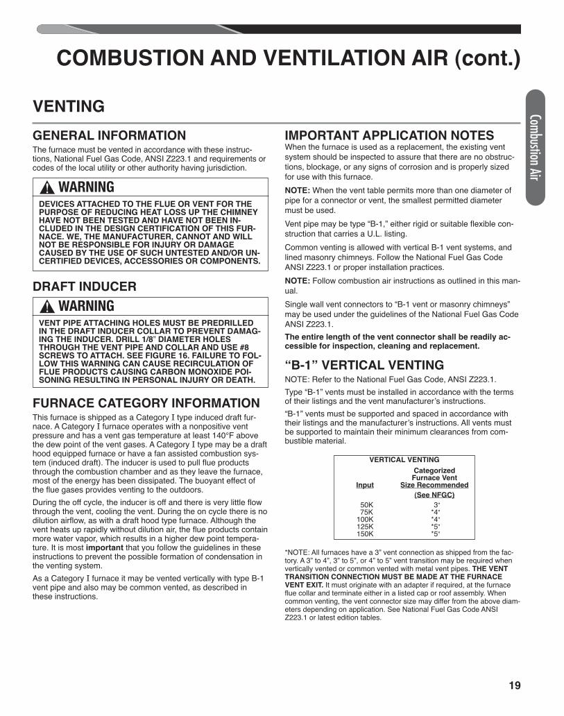
GENERAL INFORMATIONThe furnace must be vented in accordance with these instruc-tions, National Fuel Gas Code, ANSI Z223.1 and requirements orcodes of the local utility or other authority having jurisdiction.
DRAFT INDUCER
FURNACE CATEGORY INFORMATIONThis furnace is shipped as a Category I type induced draft fur-nace. A Category I furnace operates with a nonpositive ventpressure and has a vent gas temperature at least 140°F abovethe dew point of the vent gases. A Category I type may be a drafthood equipped furnace or have a fan assisted combustion sys-tem (induced draft). The inducer is used to pull flue productsthrough the combustion chamber and as they leave the furnace,most of the energy has been dissipated. The buoyant effect ofthe flue gases provides venting to the outdoors.During the off cycle, the inducer is off and there is very little flowthrough the vent, cooling the vent. During the on cycle there is nodilution airflow, as with a draft hood type furnace. Although thevent heats up rapidly without dilution air, the flue products containmore water vapor, which results in a higher dew point tempera-ture. It is most important that you follow the guidelines in theseinstructions to prevent the possible formation of condensation inthe venting system.As a Category I furnace it may be vented vertically with type B-1vent pipe and also may be common vented, as described inthese instructions.
IMPORTANT APPLICATION NOTESWhen the furnace is used as a replacement, the existing ventsystem should be inspected to assure that there are no obstruc-tions, blockage, or any signs of corrosion and is properly sizedfor use with this furnace.NOTE: When the vent table permits more than one diameter ofpipe for a connector or vent, the smallest permitted diametermust be used.Vent pipe may be type “B-1,” either rigid or suitable flexible con-struction that carries a U.L. listing.Common venting is allowed with vertical B-1 vent systems, andlined masonry chimneys. Follow the National Fuel Gas CodeANSI Z223.1 or proper installation practices.NOTE: Follow combustion air instructions as outlined in this man-ual.Single wall vent connectors to “B-1 vent or masonry chimneys”may be used under the guidelines of the National Fuel Gas CodeANSI Z223.1.The entire length of the vent connector shall be readily ac-cessible for inspection, cleaning and replacement.
“B-1” VERTICAL VENTINGNOTE: Refer to the National Fuel Gas Code, ANSI Z223.1.Type “B-1” vents must be installed in accordance with the termsof their listings and the vent manufacturer’s instructions.“B-1” vents must be supported and spaced in accordance withtheir listings and the manufacturer’s instructions. All vents mustbe supported to maintain their minimum clearances from com-bustible material.
*NOTE: All furnaces have a 3” vent connection as shipped from the fac-tory. A 3” to 4”, 3” to 5”, or 4” to 5” vent transition may be required whenvertically vented or common vented with metal vent pipes. THE VENTTRANSITION CONNECTION MUST BE MADE AT THE FURNACEVENT EXIT. It must originate with an adapter if required, at the furnaceflue collar and terminate either in a listed cap or roof assembly. Whencommon venting, the vent connector size may differ from the above diam-eters depending on application. See National Fuel Gas Code ANSIZ223.1 or latest edition tables.
! WARNINGDEVICES ATTACHED TO THE FLUE OR VENT FOR THEPURPOSE OF REDUCING HEAT LOSS UP THE CHIMNEYHAVE NOT BEEN TESTED AND HAVE NOT BEEN IN-CLUDED IN THE DESIGN CERTIFICATION OF THIS FUR-NACE. WE, THE MANUFACTURER, CANNOT AND WILLNOT BE RESPONSIBLE FOR INJURY OR DAMAGECAUSED BY THE USE OF SUCH UNTESTED AND/OR UN-CERTIFIED DEVICES, ACCESSORIES OR COMPONENTS.
! WARNINGVENT PIPE ATTACHING HOLES MUST BE PREDRILLEDIN THE DRAFT INDUCER COLLAR TO PREVENT DAMAG-ING THE INDUCER. DRILL 1/8” DIAMETER HOLESTHROUGH THE VENT PIPE AND COLLAR AND USE #8SCREWS TO ATTACH. SEE FIGURE 16. FAILURE TO FOL-LOW THIS WARNING CAN CAUSE RECIRCULATION OFFLUE PRODUCTS CAUSING CARBON MONOXIDE POI-SONING RESULTING IN PERSONAL INJURY OR DEATH.
VENTING
VERTICAL VENTING
Categorized Furnace Vent Input Size Recommended
(See NFGC)
50K 3” 75K *4” 100K *4” 125K *5” 150K *5”
Combustion Air
20
Comb
ustio
n Air
COMBUSTION AND VENTILATION AIR (cont.)
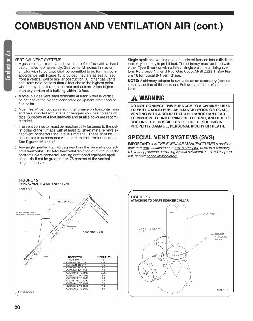
VERTICAL VENT SYSTEMS:1. A gas vent shall terminate above the roof surface with a listed
cap or listed roof assembly. Gas vents 12 inches in size orsmaller with listed caps shall be permitted to be terminated inaccordance with Figure 15, provided they are at least 8 feetfrom a vertical wall or similar obstruction. All other gas ventsshall terminate not less than 2 feet above the highest pointwhere they pass through the roof and at least 2 feet higherthan any portion of a building within 10 feet.
2. A type B-1 gas vent shall terminate at least 5 feet in verticalheight above the highest connected equipment draft hood orflue collar.
3. Must rise 1/4” per foot away from the furnace on horizontal runsand be supported with straps or hangers so it has no sags ordips. Supports at 4 foot intervals and at all elbows are recom-mended.
4. The vent connector must be mechanically fastened to the out-let collar of the furnace with at least (2) sheet metal screws ex-cept vent connectors that are B-1 material. These shall beassembled in accordance with the manufacturer’s instructions.See Figures 16 and 17.
5. Any angle greater than 45 degrees from the vertical is consid-ered horizontal. The total horizontal distance of a vent plus thehorizontal vent connector serving draft-hood equipped appli-ances shall not be greater than 75 percent of the verticalheight of the vent.
Single appliance venting of a fan assisted furnace into a tile-linedmasonry chimney is prohibited. The chimney must be lined witheither Type B vent or with a listed, single wall, metal lining sys-tem. Reference National Fuel Gas Code, ANSI Z223.1. See Fig-ure 18 for typical B-1 vent chase.NOTE: A chimney adapter is available as an accessory (see ac-cessory section of this manual). Follow manufacturer’s instruc-tions.
SPECIAL VENT SYSTEMS (SVS)IMPORTANT: It is THE FURNACE MANUFACTURER’s positionnow that new installations of any HTPV pipe used in a categoryIII vent application, including Selkirk’s Selvent™ II HTPV prod-uct, should cease immediately.
! WARNINGDO NOT CONNECT THIS FURNACE TO A CHIMNEY USEDTO VENT A SOLID FUEL APPLIANCE (WOOD OR COAL).VENTING WITH A SOLID FUEL APPLIANCE CAN LEADTO IMPROPER FUNCTIONING OF THE UNIT, AND DUE TOSOOTING, THE POSSIBILITY OF FIRE RESULTING INPROPERTY DAMAGE, PERSONAL INJURY OR DEATH.
A0991-01
FIGURE 16ATTACHING TO DRAFT INDUCER COLLAR
LISTED CAP
LISTED GAS VENT
ROOF PITCH = X/1212
X
- MINIMUM ALLOWABLE HEIGHT FROM ROOF TO DISCHARGE OPENING
ROOF PITCH “H” (MIN.) FT. FLAT TO 6/12 1.0
OVER 6/12 TO 7/12 1.25 OVER 7/12 TO 8/12 1.5 OVER 8/12 TO 9/12 2.0 OVER 9/12 TO 10/12 2.5 OVER 10/12 TO 11/12 3.25 OVER 11/12 TO 12/12 4.0 OVER 12/12 TO 14/12 5.0 OVER 14/12 TO 16/12 6.0 OVER 16/12 TO 18/12 7.0 OVER 18/12 TO 20/12 7.5 OVER 20/12 TO 21/12 8.0
ST-A1220-24
FIGURE 15TYPICAL VENTING WITH “B-1” VENT
ST-A1220-24
21
COMBUSTION AND VENTILATION AIR (cont.)
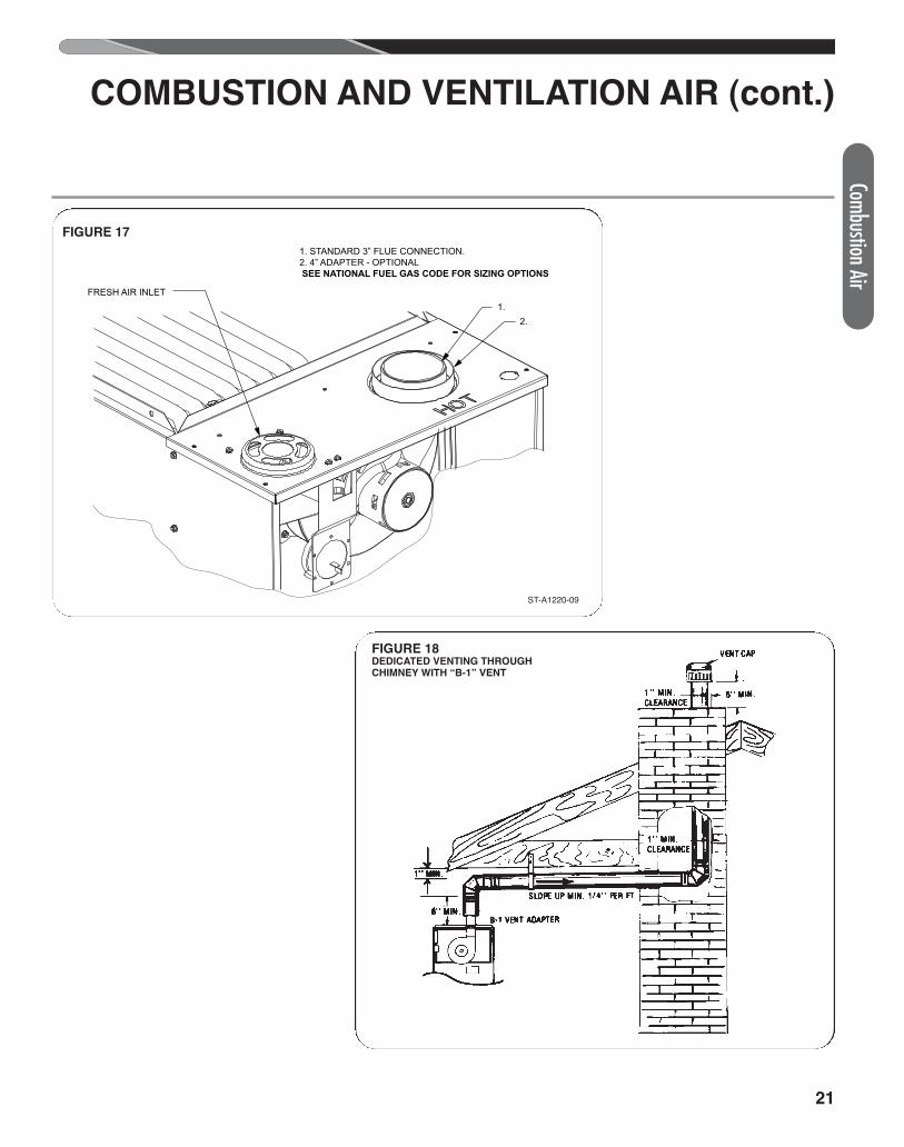
FIGURE 17
FIGURE 18DEDICATED VENTING THROUGHCHIMNEY WITH “B-1” VENT
FRESH AIR INLET
ST-A1220-09-01
1. STANDARD 3” FLUE CONNECTION.2. 4” ADAPTER - OPTIONAL SEE NATIONAL FUEL GAS CODE FOR SIZING OPTIONS
1.2.
ST-A1220-09
Combustion Air
22
COMBUSTION AND VENTILATION AIR (cont.)
POWER VENT SYSTEMSWhen vertical venting is not possible, the only acceptable methodfor horizontal venting is with the use of Tjernlund model GPAK-1TR or Field Controls models SWG-4R power venter. Type Bvent pipe and fittings must be used. Common venting is not per-mittedAll application and installation instructions supplied with thepower venter must be followed.
Please address all questions regarding power venter installation,agency listings and furnace model compatibility to:
Tjernlund Products, Inc.(800) 255-4208 or (612) 426-2993Field Controls L.L.C.(800) 742-8368 or (919) 522-0214
EXISTING VENT SYSTEMSIMPORTANT RETROFITVENTING INSTRUCTIONSIf this furnace is a replacement installation, ALWAYS INSPECTthe existing vent system to be sure there are no obstructions,blockages, or signs of corrosion.When the existing furnace is removed from a venting systemserving other appliances, the venting is likely to be too large toproperly vent the remaining attached appliances.The following steps shall be followed with each appliance that re-mains connected to the common venting system, while the otherappliances that remain connected to the common venting sys-tems are not in operation.NOTE: When the vent table permits more than one diameterof pipe for a connector or vent, the smallest permitted diam-eter must be used.1. Seal any unused openings in the com-mon venting system.
NOTE: Ensure existing venting system complies with latest addi-tion of National Fuel Gas Code ANSI Z223.1 and all localcodes/regulations.
1. Visually inspect the venting system for proper size and hori-zontal pitch and determine that there is no blockage, restric-tion, leakage, corrosion or other deficiencies which couldcause an unsafe condition.
2. Insofar as is practical, close all building doors, windows and alldoors between the space where the appliances remaining con-nected to the common venting system are located. Turn onclothes dryers and any appliance not connected to the com-mon venting system. Turn on any exhaust fans, such as rangehoods and bathroom exhausts, so they will operate at maxi-mum speed. Do not operate a summer exhaust fan. Close fire-place dampers.
3. Follow the lighting instructions. Place the appliance being in-spected into operation. Adjust the thermostat so the appliancewill operate continuously.
4. Test for spillage at the draft hood relief opening after 5 minutesof main burner operation. Use the flame of a match or candle,or smoke from a cigarette, cigar, or pipe.
5. After it has been determined that each appliance that remainsconnected to the common venting system properly vents(when tested as outlined above) return doors, windows, ex-haust fans, fireplace dampers and any other gas-burning appli-ance to their previous conditions of use.
6. If improper venting is observed during any of the above tests,the common venting system must be resized. Refer to Na-tional Fuel Gas Code, ANSI Z223.1.
Comb
ustio
n Air
23
Gas Supply
IMPORTANT SAFETY INFORMATION
NATURAL GAS AND PROPANE(LIQUEFIED PETROLEUM GAS / LPG)SAFETY
GAS SUPPLY
GAS SUPPLY
GAS SUPPLY AND PIPING
! WARNING• FURNACES USING PROPANE GAS ARE DIFFER-
ENT FROM NATURAL GAS MODELS. A NATURALGAS HEATER WILL NOT FUNCTION SAFELY ONPROPANE AND VICE VERSA. CONVERSIONS OFHEATER GAS TYPE SHOULD ONLY BE MADE BYQUALIFIED INSTALLERS USING FACTORY SUP-PLIED COMPONENTS. THE FURNACE SHOULDONLY USE THE FUEL TYPE IN ACCORDANCEWITH LISTING ON RATING PLATE. ANY OTHERFUEL USAGE WILL RESULT IN DEATH OR SERI-OUS PERSONAL INJURY FROM FIRE AND/OR EX-PLOSION.
• BOTH NATURAL GAS AND PROPANE HAVE ANODORANT ADDED TO AID IN DETECTING A GASLEAK. SOME PEOPLE MAY NOT PHYSICALLY BEABLE TO SMELL OR RECOGNIZE THIS ODORANT.IF YOU ARE UNSURE OR UNFAMILIAR WITH THESMELL OF NATURAL GAS OR PROPANE, ASKYOUR LOCAL GAS SUPPLIER. OTHER CONDI-TIONS, SUCH AS “ODORANT FADE,” WHICHCAUSES THE ODORANT TO DIMINISH IN INTEN-SITY, CAN ALSO HIDE, CAMOUFLAGE, OR OTH-ERWISE MAKE DETECTING A GAS LEAK BYSMELL MORE DIFFICULT.
• UL OR CSA RECOGNIZED FUEL GAS DETECTORSARE RECOMMENDED IN ALL ENCLOSEDPROPANE AND NATURAL GAS APPLICATIONSWHEREIN THERE IS A POTENTIAL FOR AN EXPLO-SIVE MIXTURE OF FUEL GAS TO ACCUMULATE.FUEL DETECTOR INSTALLATION SHOULD BE INACCORDANCE WITH THE DETECTOR MANUFAC-TURER’S RECOMMENDATIONS AND/OR LOCALLAWS, RULES, REGULATIONS, OR CUSTOMS.
• BEFORE ATTEMPTING TO LIGHT THE FURNACE,MAKE SURE TO LOOK AND SMELL FOR GASLEAKS. USE A SOAPY SOLUTION TO CHECK ALLGAS FITTINGS AND CONNECTIONS.
BUBBLING AT A CONNECTION INDICATES A LEAKTHAT MUST BE CORRECTED. WHEN SMELLING TODETECT A GAS LEAK, BE SURE TO ALSO SNIFFNEAR THE FLOOR. PROPANE GAS IS HEAVIERTHAN AIR AND TENDS TO COLLECT AT LOWERLEVELS MAKING IT MORE DIFFICULT TO SMELL ATNOSE LEVEL. NATURAL GAS IS LIGHTER THAN AIR
AND WILL RISE, POSSIBLY ACCUMULATING INHIGHER PORTIONS OF THE STRUCTURE.
• IF A GAS LEAK IS PRESENT OR SUSPECTED:
- DO NOT ATTEMPT TO FIND THE CAUSE YOUR-SELF.
- NEVER USE AN OPEN FLAME TO TEST FORGAS LEAKS. THE GAS CAN IGNITE RESULTINGIN DEATH, PERSONAL INJURY, OR PROPERTYDAMAGE.
- DO NOT TRY TO LIGHT ANY APPLIANCE.
- DO NOT TOUCH AND ELECTRICAL SWITCH.
- DO NOT USE ANY PHONE IN YOUR BUILDING.
- LEAVE THE BUILDING IMMEDIATELY AND CALLTHE GAS SUPPLIER FROM A NEIGHBOR’SPHONE. FOLLOW THE GAS SUPPLIER’S IN-STRUCTIONS.
- IF YOU CANNOT REACH YOUR GAS SUPPLIER,CALL THE FIRE DEPARTMENT.
- DO NOT RETURN TO THE BUILDING UNTIL AU-THORIZED BY THE GAS SUPPLIER OR FIRE DE-PARTMENT.
• SHOULD OVERHEATING OCCUR OR THE GASSUPPLY FAIL TO SHUT OFF, TURN OFF THE MAN-UAL GAS CONTROL VALVE TO THE FURNACE.
• CONSULT WITH THE LOCAL BUILDING DEPART-MENT AND FUEL GAS SUPPLIER BEFORE IN-STALLING THE HEATER:
- THE INSTALLATION AND PURGING OF GAS PIP-ING MUST CONFORM TO LOCAL CODES, UTIL-ITY COMPANY REQUIREMENTS, AND THELATEST EDITION OF NATIONAL FUEL GASCODE (NFGC) - ANSI Z223.1/NFPA 54.
- LP FURNACES SHOULD NOT BE INSTALLEDBELOW GRADE (IN A BASEMENT FOR EXAM-PLE) IF SUCH INSTALLATION IS PROHIBITED BYFEDERAL, STATE, PROVINCIAL, AND/OR LOCALLAWS, RULES, REGULATIONS, OR CUSTOMS.
- INSTALLATION OF A GAS PRESSURE REGULA-TOR MAY BE REQUIRED IN THE GAS SUPPLYLINE. THE REGULATOR SHOULD NOT EXCEEDTHE MAXIMUM SUPPLY PRESSURE LISTED ONTHE FURNACE RATING PLATE. DO NOT USE ANINDUSTRIAL-TYPE GAS REGULATOR.
- FOLLOW ALL LOCAL CODES AND SECTION 8.3OF NFGC WITH REGARD TO PURGING OF GASPIPING TO ENSURE THAT THE AIR AND/ORFUEL GAS IN THE GAS PIPING IS PROPERLYVENTED TO A LOCATION WHERE AN EXPLO-SIVE MIXTURE CANNOT ACCUMULATE.
(Continued on next column)
24
Gas S
upply
GAS SUPPLY
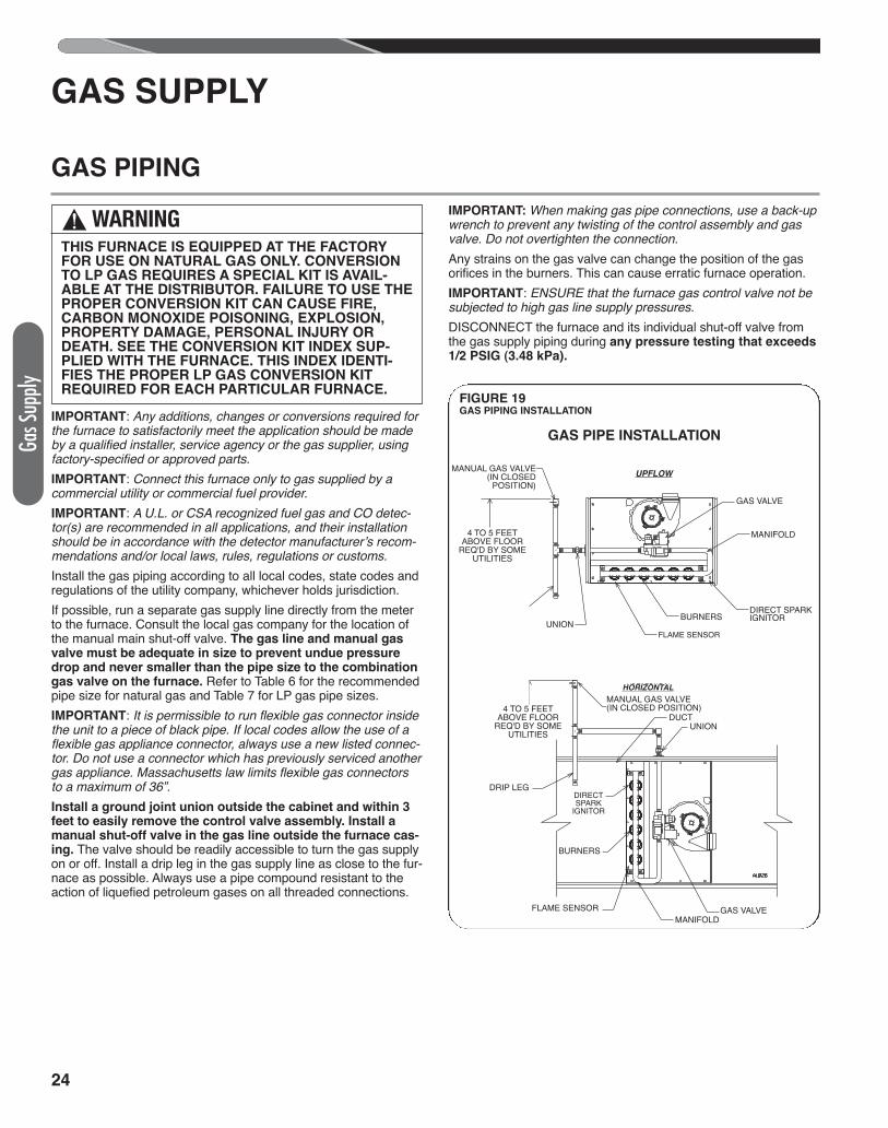
IMPORTANT: Any additions, changes or conversions required forthe furnace to satisfactorily meet the application should be madeby a qualified installer, service agency or the gas supplier, usingfactory-specified or approved parts.IMPORTANT: Connect this furnace only to gas supplied by acommercial utility or commercial fuel provider.IMPORTANT: A U.L. or CSA recognized fuel gas and CO detec-tor(s) are recommended in all applications, and their installationshould be in accordance with the detector manufacturer’s recom-mendations and/or local laws, rules, regulations or customs.Install the gas piping according to all local codes, state codes andregulations of the utility company, whichever holds jurisdiction. If possible, run a separate gas supply line directly from the meterto the furnace. Consult the local gas company for the location ofthe manual main shut-off valve. The gas line and manual gasvalve must be adequate in size to prevent undue pressuredrop and never smaller than the pipe size to the combinationgas valve on the furnace. Refer to Table 6 for the recom mendedpipe size for natural gas and Table 7 for LP gas pipe sizes. IMPORTANT: It is permissible to run flexible gas connector insidethe unit to a piece of black pipe. If local codes allow the use of aflexible gas appliance connector, always use a new listed connec-tor. Do not use a connector which has previously serviced anothergas appliance. Massachusetts law limits flexible gas connectorsto a maximum of 36”.Install a ground joint union outside the cabinet and within 3feet to easily remove the control valve assembly. Install amanual shut-off valve in the gas line outside the furnace cas-ing. The valve should be readily accessible to turn the gas supplyon or off. Install a drip leg in the gas supply line as close to the fur-nace as possible. Always use a pipe compound resistant to theaction of liquefied petroleum gases on all threaded connections.
IMPORTANT: When making gas pipe connections, use a back-upwrench to prevent any twisting of the control assembly and gasvalve. Do not overtighten the connection. Any strains on the gas valve can change the position of the gasorifices in the burners. This can cause erratic furnace operation.IMPORTANT: ENSURE that the furnace gas control valve not besubjected to high gas line supply pressures. DISCONNECT the furnace and its individual shut-off valve fromthe gas supply piping during any pressure testing that exceeds1/2 PSIG (3.48 kPa).
GAS PIPE INSTALLATION
GAS VALVE
MANIFOLD
MANIFOLD
FLAME SENSOR
FLAME SENSOR
BURNERS
BURNERS
DIRECT SPARKIGNITOR
DIRECTSPARK
IGNITOR
MANUAL GAS VALVE (IN CLOSED POSITION)
UNION
DUCTUNION
DRIP LEG
DRIP LEG
4 TO 5 FEETABOVE FLOOR
REQ'D BY SOMEUTILITIES
4 TO 5 FEETABOVE FLOOR
REQ'D BY SOMEUTILITIES
UPFLOW
HORIZONTAL
GAS VALVE
FIGURE 19GAS PIPING INSTALLATION
MANUAL GAS VALVE(IN CLOSED
POSITION)
GAS PIPING
! WARNINGTHIS FURNACE IS EQUIPPED AT THE FACTORYFOR USE ON NATURAL GAS ONLY. CONVERSIONTO LP GAS REQUIRES A SPECIAL KIT IS AVAIL-ABLE AT THE DISTRIBUTOR. FAILURE TO USE THEPROPER CONVERSION KIT CAN CAUSE FIRE,CARBON MONOXIDE POISONING, EXPLOSION,PROPERTY DAMAGE, PERSONAL INJURY ORDEATH. SEE THE CONVERSION KIT INDEX SUP-PLIED WITH THE FURNACE. THIS INDEX IDENTI-FIES THE PROPER LP GAS CONVERSION KITREQUIRED FOR EACH PARTICULAR FURNACE.
25
GAS SUPPLY (cont.)
IMPORTANT: ENSURE that the furnace gas valve is not to besubjected to high gas line supply pressures. DISCONNECT the furnace and its individual manual gas stopfrom the gas supply piping during any pressure testing that ex-ceeds 1/2 PSIG. (3.48 kPa).
Natural gas supply pressure must be 5" to 10.5" w.c. LP gassupply pressure must be 11" to 13" w.c. This pressure mustbe maintained with all other gas-fired appliances in opera-tion.
The minimum gas supply pressure to the gas valve for proper fur-nace input adjustments is 5" w.c. for natural gas, however 6" to 7"is recommended. The minimum gas supply pressure is 11" w.c.for LP gas.
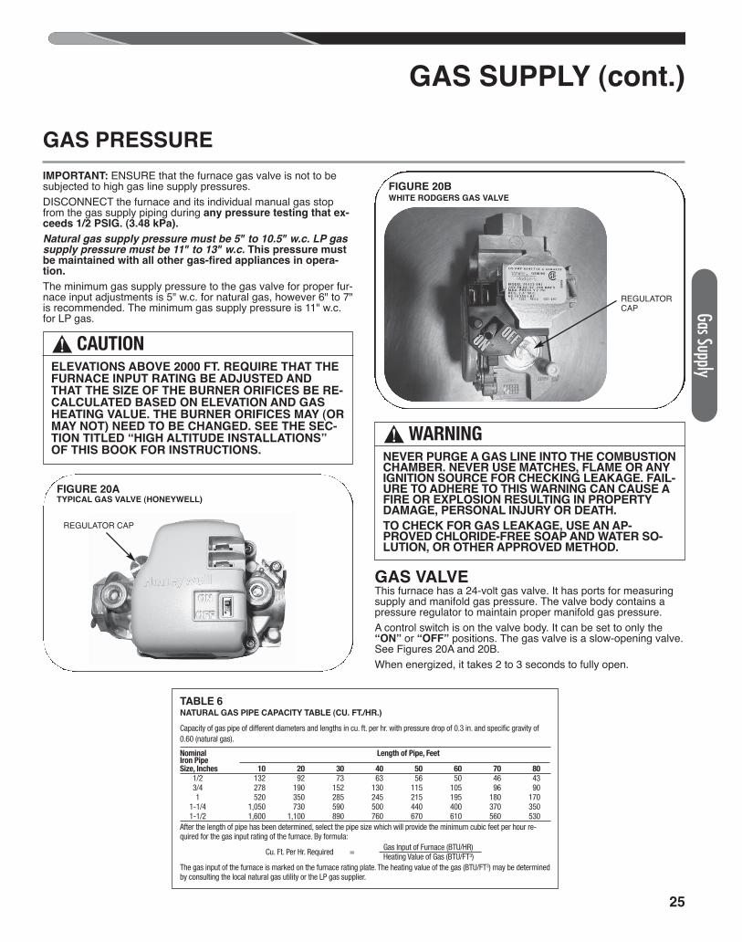
GAS VALVEThis furnace has a 24-volt gas valve. It has ports for measuringsupply and manifold gas pressure. The valve body contains apressure regulator to maintain proper manifold gas pressure. A control switch is on the valve body. It can be set to only the“ON” or “OFF” positions. The gas valve is a slow-opening valve.See Figures 20A and 20B.When energized, it takes 2 to 3 seconds to fully open.
GAS PRESSURE
! CAUTIONELEVATIONS ABOVE 2000 FT. REQUIRE THAT THEFURNACE INPUT RATING BE ADJUSTED ANDTHAT THE SIZE OF THE BURNER ORIFICES BE RE-CALCULATED BASED ON ELEVATION AND GASHEATING VALUE. THE BURNER ORIFICES MAY (ORMAY NOT) NEED TO BE CHANGED. SEE THE SEC-TION TITLED “HIGH ALTITUDE INSTALLATIONS”OF THIS BOOK FOR INSTRUCTIONS.
FIGURE 20ATYPICAL GAS VALVE (HONEYWELL)
REGULATOR CAP
! WARNINGNEVER PURGE A GAS LINE INTO THE COMBUSTIONCHAMBER. NEVER USE MATCHES, FLAME OR ANYIGNITION SOURCE FOR CHECKING LEAKAGE. FAIL-URE TO ADHERE TO THIS WARNING CAN CAUSE AFIRE OR EXPLOSION RESULTING IN PROPERTYDAMAGE, PERSONAL INJURY OR DEATH.
TO CHECK FOR GAS LEAKAGE, USE AN AP-PROVED CHLORIDE-FREE SOAP AND WATER SO-LUTION, OR OTHER APPROVED METHOD.
TABLE 6NATURAL GAS PIPE CAPACITY TABLE (CU. FT./HR.)
Capacity of gas pipe of different diameters and lengths in cu. ft. per hr. with pressure drop of 0.3 in. and specific gravity of0.60 (natural gas).
Nominal Length of Pipe, FeetIron PipeSize, Inches 10 20 30 40 50 60 70 80 1/2 132 92 73 63 56 50 46 43 3/4 278 190 152 130 115 105 96 90 1 520 350 285 245 215 195 180 170 1-1/4 1,050 730 590 500 440 400 370 350 1-1/2 1,600 1,100 890 760 670 610 560 530After the length of pipe has been determined, select the pipe size which will provide the minimum cubic feet per hour re-quired for the gas input rating of the furnace. By formula: Gas Input of Furnace (BTU/HR) Cu. Ft. Per Hr. Required = Heating Value of Gas (BTU/FT3)The gas input of the furnace is marked on the furnace rating plate. The heating value of the gas (BTU/FT3) may be determinedby consulting the local natural gas utility or the LP gas supplier.
Gas Supply
FIGURE 20BWHITE RODGERS GAS VALVE
REGULATORCAP
26
GAS SUPPLY (cont.)
SETTING GAS PRESSUREThe maximum gas supply pressure to the furnace must notexceed 10.5" w.c. natural gas, or 13" w.c. LP gas. The mini-mum supply gas pressure to the gas valve should be 5� w.c. nat-ural gas or 11� w.c. LP gas. A properly calibrated manometer isrequired for accurate gas pressure measurements.
SUPPLY GAS PRESSUREMEASUREMENTAn inlet pressure tap is on the input side of the gas valve. 1. With gas shut off to the furnace at the manual gas valve out-
side the unit, remove the inlet pressure tap plug. 2. Connect a manometer to the pressure tap. 3. Turn on the gas supply and operate the furnace and all other
gas-fired units on the same gas line as the furnace. 4. Note or adjust the line gas pressure to give: A. 5� - 10.5� w.c. for natural gas. B. 11� - 13� w.c. for LP gas. 5. Shut off the gas at the manual gas valve and remove the
manometer and hose. 6. Replace the pressure tap plug before turning on the gas. 7. Turn on the gas supply and check for gas leaks using an ap-
proved leak detector. Do NOT use a flame of any kind tocheck for leaks. Repair any leaks and repeat.
If the supply gas line pressure is above these ranges,a high pres-sure in line gas regulator may be required. Consult local gas util-ity. With LP gas, have the LP supplier reduce the line pressure atthe regulator. If supply gas line pressure is below these ranges, either removeany restrictions in the gas supply piping or enlarge the gas pipe.See Tables 6 and 7. With LP gas, have the LP supplier adjust theline pressure at the regulator.
MANIFOLD GAS PRESSURE MEASUREMENTNatural gas manifold pressure should be 3.5" (± .3) w.c. LPgas manifold pressure should be 10.0" (± .5) w.c. Only smallvariations in gas pressure should be made by adjusting the pres-sure regulator. 1. With the gas to the unit shut off at the manual gas valve, re-
move the outlet pressure tap plug. 2. Connect a manometer to this pressure tap. 3. Turn on the gas supply and operate the furnace (apply a
heat call). 4. Note or adjust the manifold gas pressure to give: A. 3.5� (± .3) w.c. for natural gas. B. 10.0� (± .5) w.c. for LP gas. 5. To adjust the pressure regulator, remove the regulator cap.
(See Figures 20A and 20B.) 6. Turn the adjustment screw clockwise to increase pressure,
or counterclockwise to decrease pressure. 7. Securely replace the regulator cap. 8. Shut off gas at the manual gas valve and remove the
manometer and hose. 9. Replace the pressure tap plug before turning on the gas.10. Turn on the gas supply and apply a heat call to the furnace
then check for gas leaks using an approved leak detector.Do NOT use a flame of any kind to check for leaks. Repairany leaks and repeat.
Gas S
upply
! CAUTIONELEVATIONS ABOVE 2000 FT. REQUIRE THAT THE FUR-
NACE INPUT RATING BE ADJUSTED AND THAT THE
SIZE OF THE BURNER ORIFICES BE RECALCULATED
BASED ON ELEVATION AND GAS HEATING VALUE. THE
BURNER ORIFICES MAY (OR MAY NOT) NEED TO BE
CHANGED. SEE THE SECTION TITLED “HIGH ALTITUDE
INSTALLATIONS” OF THIS BOOK FOR INSTRUCTIONS.
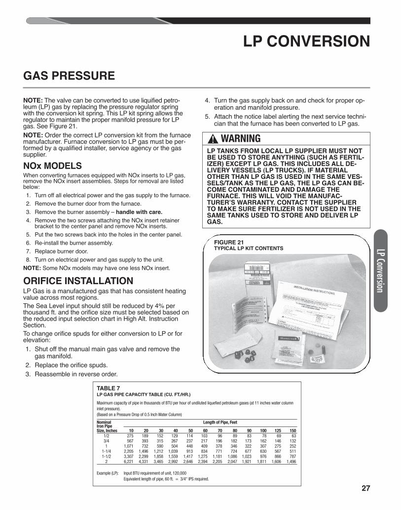
27
TABLE 7LP GAS PIPE CAPACITY TABLE (CU. FT./HR.)
Maximum capacity of pipe in thousands of BTU per hour of undiluted liquefied petroleum gases (at 11 inches water columninlet pressure).(Based on a Pressure Drop of 0.5 Inch Water Column)
Nominal Length of Pipe, FeetIron PipeSize, Inches 10 20 30 40 50 60 70 80 90 100 125 150 1/2 275 189 152 129 114 103 96 89 83 78 69 63 3/4 567 393 315 267 237 217 196 182 173 162 146 132 1 1,071 732 590 504 448 409 378 346 322 307 275 252 1-1/4 2,205 1,496 1,212 1,039 913 834 771 724 677 630 567 511 1-1/2 3,307 2,299 1,858 1,559 1,417 1,275 1,181 1,086 1,023 976 866 787 2 6,221 4,331 3,465 2,992 2,646 2,394 2,205 2,047 1,921 1,811 1,606 1,496
Example (LP): Input BTU requirement of unit, 120,000 Equivalent length of pipe, 60 ft. = 3/4" IPS required.
LP CONVERSION
LP Conversion
NOTE: The valve can be converted to use liquified petro-leum (LP) gas by replacing the pressure regulator springwith the conversion kit spring. This LP kit spring allows theregulator to maintain the proper manifold pressure for LPgas. See Figure 21.NOTE: Order the correct LP conversion kit from the furnacemanufacturer. Furnace conversion to LP gas must be per-formed by a qualified installer, service agency or the gassupplier.
NOx MODELSWhen converting furnaces equipped with NOx inserts to LP gas,remove the NOx insert assemblies. Steps for removal are listedbelow: 1. Turn off all electrical power and the gas supply to the furnace. 2. Remove the burner door from the furnace. 3. Remove the burner assembly – handle with care.
4. Remove the two screws attaching the NOx insert retainerbracket to the center panel and remove NOx inserts.
5. Put the two screws back into the holes in the center panel. 6. Re-install the burner assembly. 7. Replace burner door. 8. Turn on electrical power and gas supply to the unit.NOTE: Some NOx models may have one less NOx insert.
ORIFICE INSTALLATIONLP Gas is a manufactured gas that has consistent heatingvalue across most regions.The Sea Level input should still be reduced by 4% perthousand ft. and the orifice size must be selected based onthe reduced input selection chart in High Alt. InstructionSection.To change orifice spuds for either conversion to LP or forelevation: 1. Shut off the manual main gas valve and remove the
gas manifold. 2. Replace the orifice spuds. 3. Reassemble in reverse order.
4. Turn the gas supply back on and check for proper op-eration and manifold pressure.
5. Attach the notice label alerting the next service techni-cian that the furnace has been converted to LP gas.
FIGURE 21TYPICAL LP KIT CONTENTS
! WARNINGLP TANKS FROM LOCAL LP SUPPLIER MUST NOTBE USED TO STORE ANYTHING (SUCH AS FERTIL-IZER) EXCEPT LP GAS. THIS INCLUDES ALL DE-LIVERY VESSELS (LP TRUCKS). IF MATERIALOTHER THAN LP GAS IS USED IN THE SAME VES-SELS/TANK AS THE LP GAS, THE LP GAS CAN BE-COME CONTAMINATED AND DAMAGE THEFURNACE. THIS WILL VOID THE MANUFAC-TURER’S WARRANTY. CONTACT THE SUPPLIERTO MAKE SURE FERTILIZER IS NOT USED IN THESAME TANKS USED TO STORE AND DELIVER LPGAS.
GAS PRESSURE
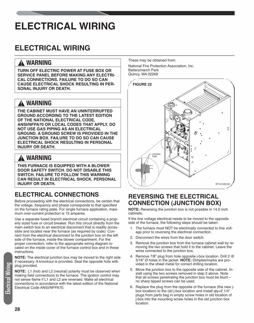
28
Electr
ical W
iring
ELECTRICAL CONNECTIONSBefore proceeding with the electrical connections, be certain thatthe voltage, frequency and phase corresponds to that specifiedon the furnace rating plate. For single furnace application, maxi-mum over-current protection is 15 amperes.Use a separate fused branch electrical circuit containing a prop-erly sized fuse or circuit breaker. Run this circuit directly from themain switch box to an electrical disconnect that is readily acces-sible and located near the furnace (as required by code). Con-nect from the electrical disconnect to the junction box on the leftside of the furnace, inside the blower compartment. For theproper connection, refer to the appropriate wiring diagram lo-cated on the inside cover of the furnace control box and in theseinstructions.NOTE: The electrical junction box may be moved to the right sideif necessary. A knockout is provided. Seal the opposite hole withplug provided.NOTE: L1 (hot) and L2 (neutral) polarity must be observed whenmaking field connections to the furnace. The ignition control maynot sense flame if L1 and L2 are reversed. Make all electricalconnections in accordance with the latest edition of the NationalElectrical Code ANSI/NFPA70.
These may be obtained from:National Fire Protection Association, Inc.Batterymarch ParkQuincy, MA 02269
REVERSING THE ELECTRICALCONNECTION (JUNCTION BOX)NOTE: Reversing the junction box is not possible in 14.0 inchcabinets.If the line voltage electrical needs to be moved to the oppositeside of the furnace, the following steps should be taken: 1. The furnace must NOT be electrically connected to line volt-
age prior to reversing the electrical connection. 2. Disconnect the wires from the door switch. 3. Remove the junction box from the furnace cabinet wall by re-
moving the two screws that hold it to the cabinet. Leave thewires connected to the junction box.
4. Remove 7/8” plug from hole opposite j-box location. Drill 2 @3/16” Ø holes in the jacket. NOTE: Dimples/marks are pro-vided in the sheet metal for correct drilling location.
5. Move the junction box to the opposite side of the cabinet. In-stall using the two screws removed in step 3 above. Notethat all screws penetrating the junction box must be blunt –no sharp tipped screws can be used.
6. Replace the plug from the opposite of the furnace (the new j-box location) to the old j-box location and install qty=2 1/4”plugs from parts bag in empty screw holes in old location ofj-box into the mounting screw holes in the old junction boxlocation.
LOCKINGTABS
ELECTRICAL WIRING
ELECTRICAL WIRING
! WARNINGTHE CABINET MUST HAVE AN UNINTERRUPTEDGROUND ACCORDING TO THE LATEST EDITIONOF THE NATIONAL ELECTRICAL CODE,ANSI/NFPA70 OR LOCAL CODES THAT APPLY. DONOT USE GAS PIPING AS AN ELECTRICALGROUND. A GROUND SCREW IS PROVIDED IN THEJUNCTION BOX. FAILURE TO DO SO CAN CAUSEELECTRICAL SHOCK RESULTING IN PERSONALINJURY OR DEATH.
! WARNINGTHIS FURNACE IS EQUIPPED WITH A BLOWERDOOR SAFETY SWITCH. DO NOT DISABLE THISSWITCH. FAILURE TO FOLLOW THIS WARNINGCAN RESULT IN ELECTRICAL SHOCK, PERSONALINJURY OR DEATH.
FIGURE 22
ST-A1220-05
! WARNINGTURN OFF ELECTRIC POWER AT FUSE BOX ORSERVICE PANEL BEFORE MAKING ANY ELECTRI-CAL CONNECTIONS. FAILURE TO DO SO CANCAUSE ELECTRICAL SHOCK RESULTING IN PER-SONAL INJURY OR DEATH.
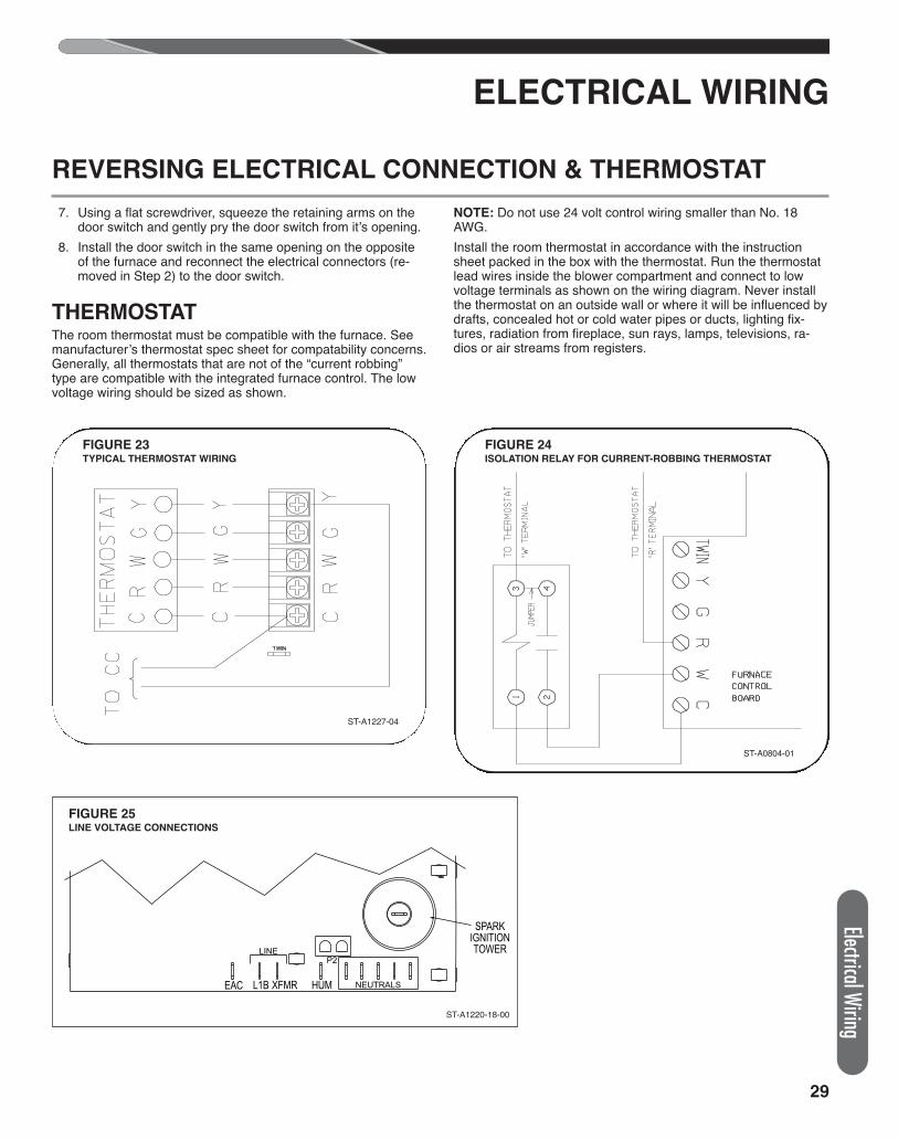
29
ELECTRICAL WIRING
7. Using a flat screwdriver, squeeze the retaining arms on thedoor switch and gently pry the door switch from it’s opening.
8. Install the door switch in the same opening on the oppositeof the furnace and reconnect the electrical connectors (re-moved in Step 2) to the door switch.
THERMOSTATThe room thermostat must be compatible with the furnace. Seemanufacturer’s thermostat spec sheet for compatability concerns.Generally, all thermostats that are not of the “current robbing”type are compatible with the integrated furnace control. The lowvoltage wiring should be sized as shown.
NOTE: Do not use 24 volt control wiring smaller than No. 18AWG.Install the room thermostat in accordance with the instructionsheet packed in the box with the thermostat. Run the thermostatlead wires inside the blower compartment and connect to lowvoltage terminals as shown on the wiring diagram. Never installthe thermostat on an outside wall or where it will be influenced bydrafts, concealed hot or cold water pipes or ducts, lighting fix-tures, radiation from fireplace, sun rays, lamps, televisions, ra-dios or air streams from registers.
REVERSING ELECTRICAL CONNECTION & THERMOSTAT
ST-A0804-01
EAC L1B XFMR HUM
SPARKIGNITIONTOWER
NEUTRALS
LINEP2
ST-A1220-18-00
FIGURE 25LINE VOLTAGE CONNECTIONS
FIGURE 24ISOLATION RELAY FOR CURRENT-ROBBING THERMOSTAT
ST-A1227-04
FIGURE 23TYPICAL THERMOSTAT WIRING
Electrical Wiring
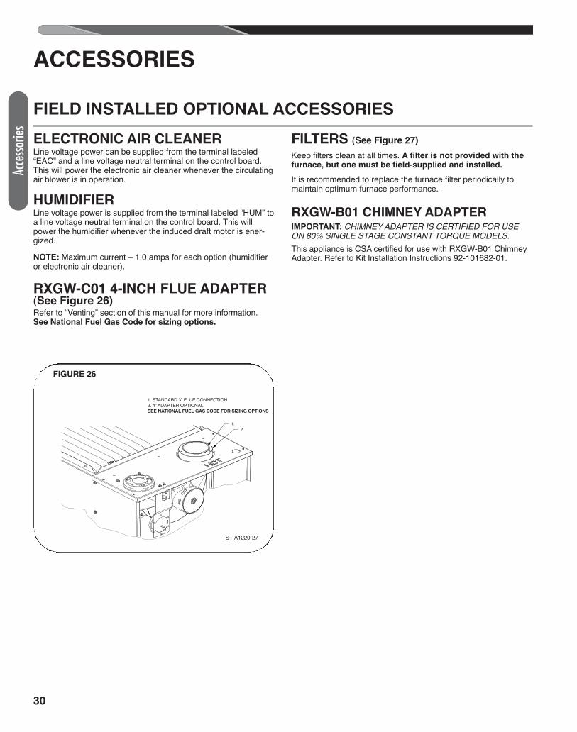
30
Acce
ssorie
s
ELECTRONIC AIR CLEANERLine voltage power can be supplied from the terminal labeled“EAC” and a line voltage neutral terminal on the control board.This will power the electronic air cleaner whenever the circulatingair blower is in operation.
HUMIDIFIERLine voltage power is supplied from the terminal labeled “HUM” toa line voltage neutral terminal on the control board. This willpower the humidifier whenever the induced draft motor is ener-gized.
NOTE: Maximum current – 1.0 amps for each option (humidifieror electronic air cleaner).
RXGW-C01 4-INCH FLUE ADAPTER(See Figure 26)Refer to “Venting” section of this manual for more information.See National Fuel Gas Code for sizing options.
FILTERS (See Figure 27)
Keep filters clean at all times. A filter is not provided with thefurnace, but one must be field-supplied and installed.
It is recommended to replace the furnace filter periodically tomaintain optimum furnace performance.
RXGW-B01 CHIMNEY ADAPTERIMPORTANT: CHIMNEY ADAPTER IS CERTIFIED FOR USEON 80% SINGLE STAGE CONSTANT TORQUE MODELS.This appliance is CSA certified for use with RXGW-B01 ChimneyAdapter. Refer to Kit Installation Instructions 92-101682-01.
ACCESSORIES
FIELD INSTALLED OPTIONAL ACCESSORIES
ST-A1220-27-00
1. STANDARD 3” FLUE CONNECTION.2. 4” ADAPTER SEE NATIONAL FUEL GAS CODE FOR SIZING OPTIONS
1.2.
ST-A1220-27
FIGURE 26
1. STANDARD 3” FLUE CONNECTION2. 4” ADAPTER OPTIONALSEE NATIONAL FUEL GAS CODE FOR SIZING OPTIONS
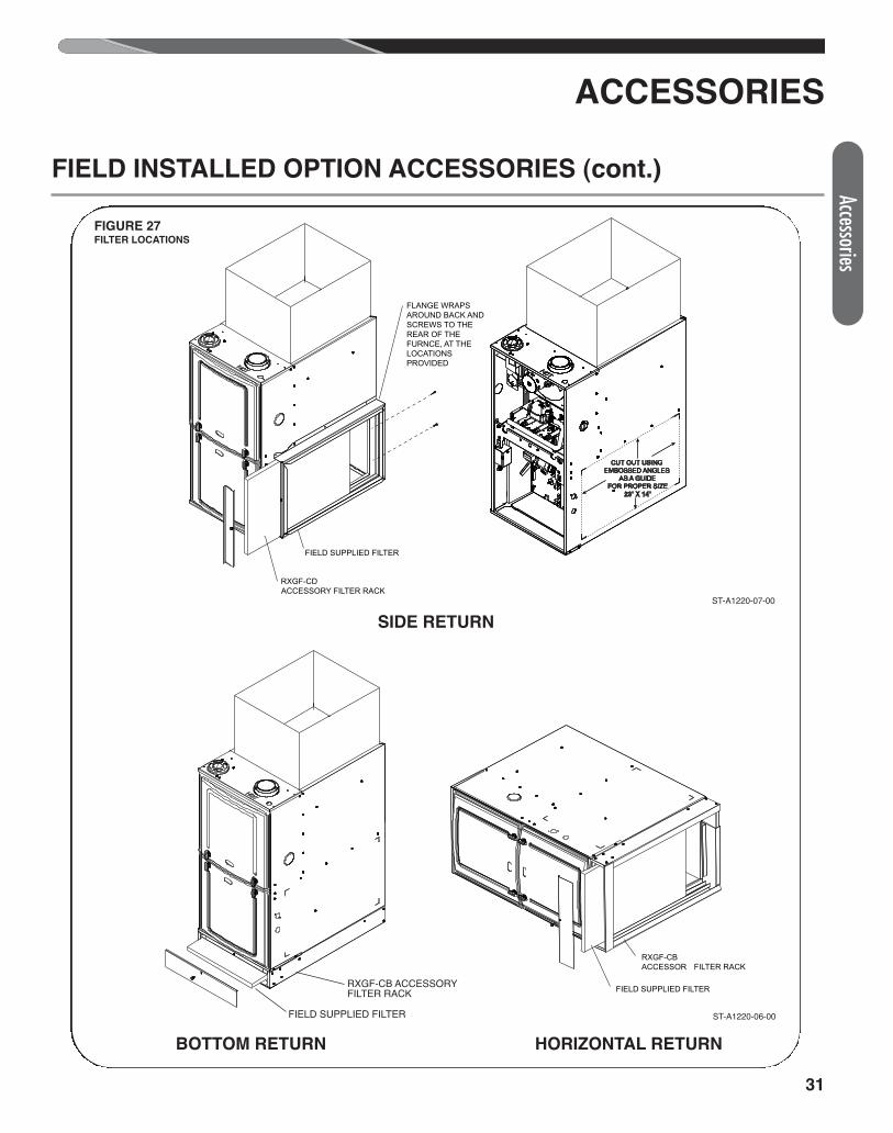
31
SIDE RETURN
BOTTOM RETURN
ST-A1220-07-X0
RXGF-CDACCESSORY FILTER RACK
FIELD SUPPLIED FILTER
FLANGE WRAPS AROUND BACK AND SCREWS TO THE REAR OF THE FURNCE, AT THE LOCATIONS PROVIDED
CUT OUT USING EMBOSSED ANGLES
AS A GUIDE FOR PROPER SIZE
23” X 14”
ST-A1220-07-00
RXGF-CB
FIELD SUPPLIED FILTER
ST-A1220-06-X0
FIGURE 27FILTER LOCATIONS
ACCESSORIES
FIELD INSTALLED OPTION ACCESSORIES (cont.)
HORIZONTAL RETURN
ST-A1220-06-00
RXGF-CB ACCESSORYFILTER RACK
FIELD SUPPLIED FILTER
Accessories
32
Twinn
ing
Twinning operation of two furnaces, installed side-by-side, con-nected by a common duct system with main power supplied bythe same source, and controlled by a common thermostat can bedone with the UT Electronic Controls 1194-250 integrated controlboards.
IMPORTANT: Only twin furnaces with identical control boards.
IMPORTANT: Only bottom returns can be used. No more thantwo furnaces can share the same supply and return. Furnacesmust have same heating and blower capacity. Twinning furnacesmust operate off the same phase of power.It should be noted that both blowers will run simultaneously whenthere is a call for heating, cooling or fan.
NOTE: Duct system must be adequate to provide correct airflowto each furnace for supply and return.
UT ELECTRONIC CONTROLS 1194-250 CONTROL BOARD(62-104058-02)1. Single Stage Operation a. Control board “ONE” is on furnace connected to the ther-
mostat. b. The 24 VAC supply to both control boards must be in
phase with each other. c. Connect the “C,” “W” and “TWIN” terminals to counter-
parts on each control. d. Twinning is automatically detected when wire is connected
to the twin terminal on both controls. If twinning is de-tected and then lost in the same power cycle, the furnacecontrol will declare and display fault code 20 at the seven-segment display.
See Figure 28 for twinning wire diagram for 1-stage thermostat.See Figure 29 for twinning wire diagram for 2-stage thermostat.
TWINNING
FURNACE TWINNING INSTALLATIONS
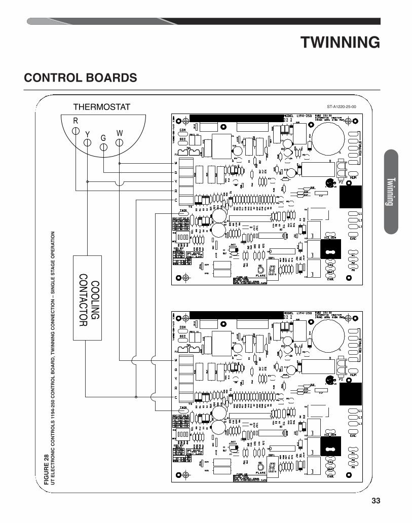
33
R
Y G W
COOLING CONTACTOR
THERMOSTAT
TWINNING
CONTROL BOARDS
FIG
UR
E 2
8U
T E
LE
CT
RO
NIC
CO
NT
RO
LS
11
94
-25
0 C
ON
TR
OL
BO
AR
D,
TW
INN
ING
CO
NN
EC
TIO
N –
SIN
GL
E S
TA
GE
OP
ER
AT
ION
ST-A1220-25-00
Twinning
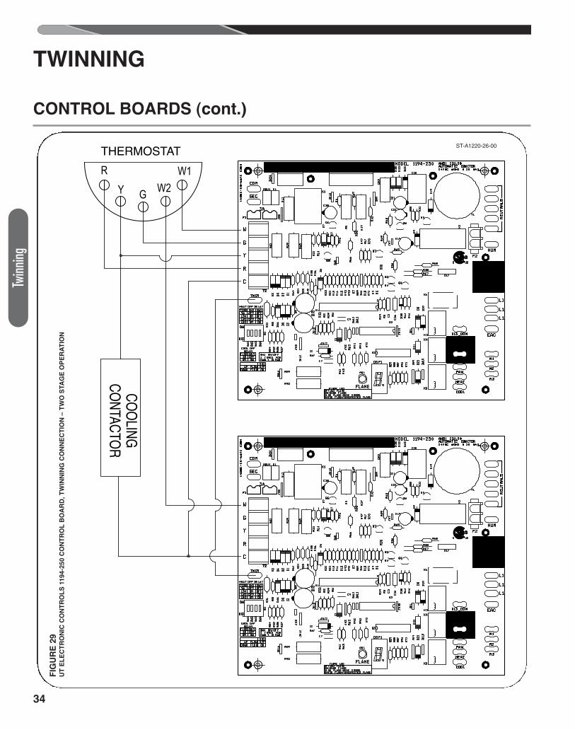
34
R
Y G W2W1
COOLING CONTACTOR
THERMOSTAT
FIG
UR
E 2
9U
T E
LE
CT
RO
NIC
CO
NT
RO
LS
11
94
-25
0 C
ON
TR
OL
BO
AR
D,
TW
INN
ING
CO
NN
EC
TIO
N –
TW
O S
TA
GE
OP
ER
AT
ION
TWINNING
CONTROL BOARDS (cont.)
ST-A1220-26-00
Twinn
ing
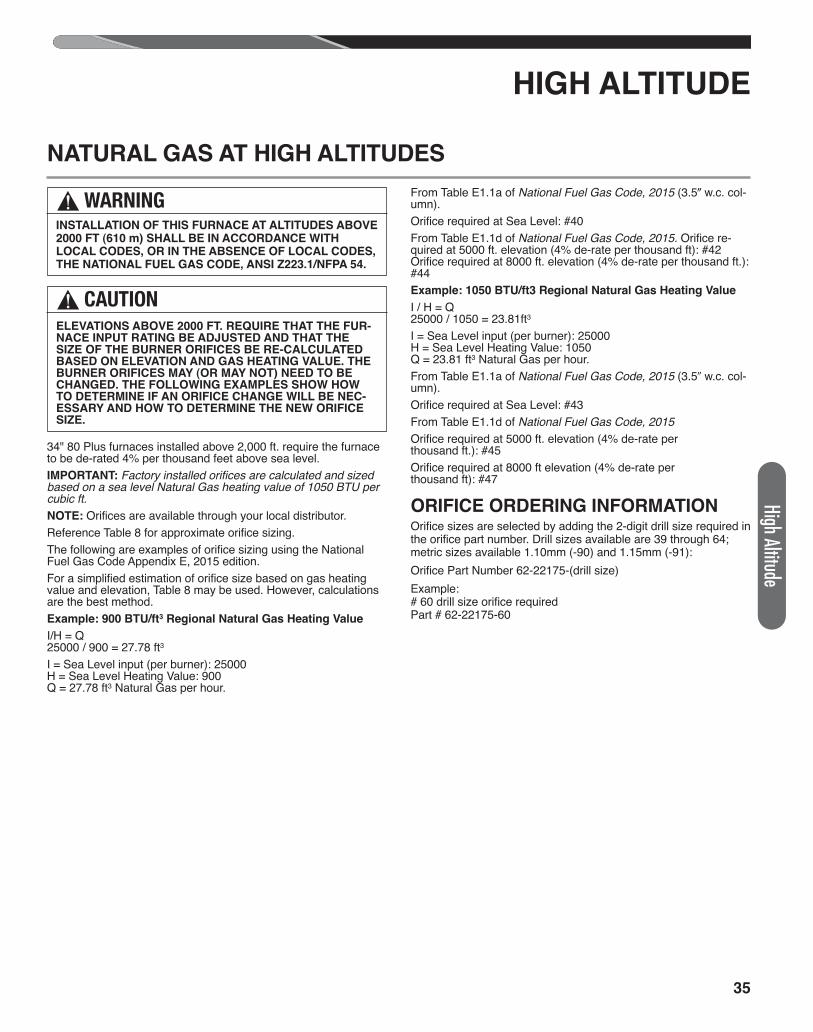
35
High Altitude
HIGH ALTITUDE
34" 80 Plus furnaces installed above 2,000 ft. require the furnaceto be de-rated 4% per thousand feet above sea level.IMPORTANT: Factory installed orifices are calculated and sizedbased on a sea level Natural Gas heating value of 1050 BTU percubic ft. NOTE: Orifices are available through your local distributor.Reference Table 8 for approximate orifice sizing.The following are examples of orifice sizing using the NationalFuel Gas Code Appendix E, 2015 edition.For a simplified estimation of orifice size based on gas heatingvalue and elevation, Table 8 may be used. However, calculationsare the best method.Example: 900 BTU/ft3 Regional Natural Gas Heating Value
I/H = Q25000 / 900 = 27.78 ft3I = Sea Level input (per burner): 25000H = Sea Level Heating Value: 900Q = 27.78 ft3 Natural Gas per hour.
From Table E1.1a of National Fuel Gas Code, 2015 (3.5� w.c. col-umn).Orifice required at Sea Level: #40From Table E1.1d of National Fuel Gas Code, 2015. Orifice re-quired at 5000 ft. elevation (4% de-rate per thousand ft): #42Orifice required at 8000 ft. elevation (4% de-rate per thousand ft.):#44Example: 1050 BTU/ft3 Regional Natural Gas Heating Value
I / H = Q25000 / 1050 = 23.81ft3I = Sea Level input (per burner): 25000H = Sea Level Heating Value: 1050Q = 23.81 ft3 Natural Gas per hour.From Table E1.1a of National Fuel Gas Code, 2015 (3.5� w.c. col-umn).Orifice required at Sea Level: #43From Table E1.1d of National Fuel Gas Code, 2015Orifice required at 5000 ft. elevation (4% de-rate per thousand ft.): #45Orifice required at 8000 ft elevation (4% de-rate per thousand ft): #47
ORIFICE ORDERING INFORMATIONOrifice sizes are selected by adding the 2-digit drill size required inthe orifice part number. Drill sizes available are 39 through 64;metric sizes available 1.10mm (-90) and 1.15mm (-91):Orifice Part Number 62-22175-(drill size)Example:# 60 drill size orifice requiredPart # 62-22175-60
NATURAL GAS AT HIGH ALTITUDES
! WARNINGINSTALLATION OF THIS FURNACE AT ALTITUDES ABOVE2000 FT (610 m) SHALL BE IN ACCORDANCE WITHLOCAL CODES, OR IN THE ABSENCE OF LOCAL CODES,THE NATIONAL FUEL GAS CODE, ANSI Z223.1/NFPA 54.
! CAUTIONELEVATIONS ABOVE 2000 FT. REQUIRE THAT THE FUR-NACE INPUT RATING BE ADJUSTED AND THAT THESIZE OF THE BURNER ORIFICES BE RE-CALCULATEDBASED ON ELEVATION AND GAS HEATING VALUE. THEBURNER ORIFICES MAY (OR MAY NOT) NEED TO BECHANGED. THE FOLLOWING EXAMPLES SHOW HOWTO DETERMINE IF AN ORIFICE CHANGE WILL BE NEC-ESSARY AND HOW TO DETERMINE THE NEW ORIFICESIZE.
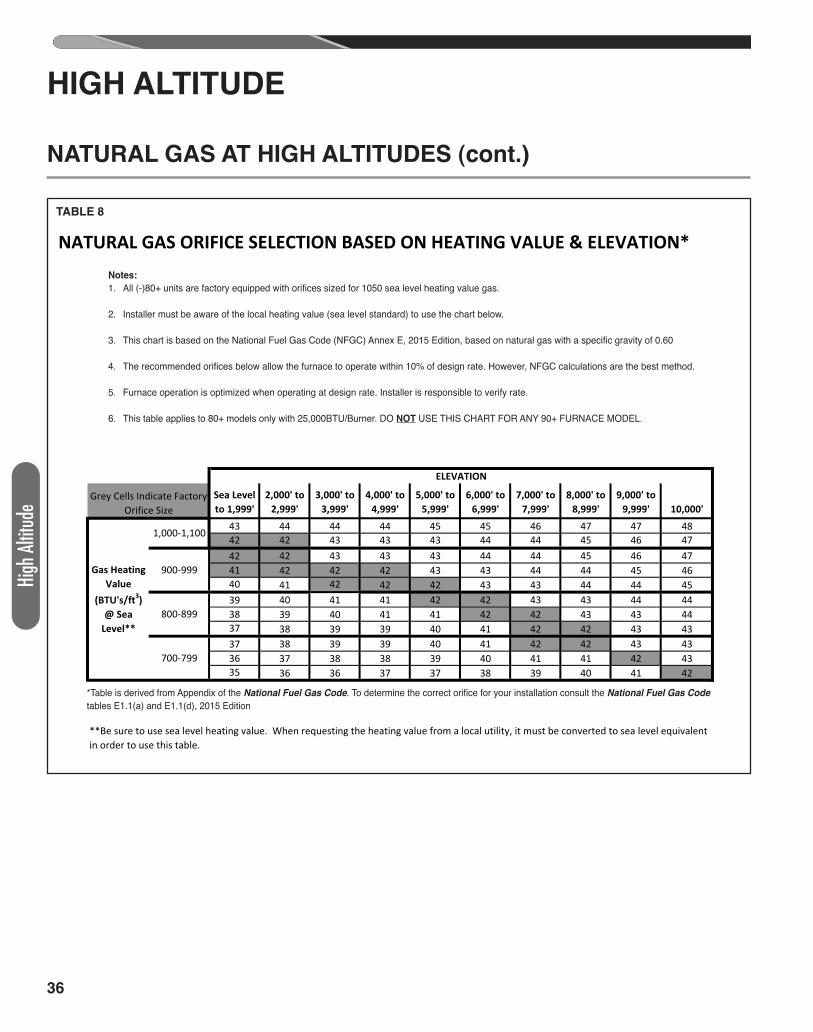
36
High
Altit
ude
TABLE 8SUPPLEMENTAL ORIFICE SIZE CHART
Sea Level to 1,999'
2,000' to 2,999'
3,000' to 3,999'
4,000' to 4,999'
5,000' to 5,999'
6,000' to 6,999'
7,000' to 7,999'
8,000' to 8,999'
9,000' to 9,999' 10,000'
43 44 44 44 45 45 46 47 47 4842 42 43 43 43 44 44 45 46 4742 42 43 43 43 44 44 45 46 4741 42 42 42 43 43 44 44 45 4640 41 42 42 42 43 43 44 44 4539 40 41 41 42 42 43 43 44 4438 39 40 41 41 42 42 43 43 4437 38 39 39 40 41 42 42 43 4337 38 39 39 40 41 42 42 43 4336 37 38 38 39 40 41 41 42 4335 36 36 37 37 38 39 40 41 42
ELEVATION
Grey Cells Indicate Factory Orifice Size
Gas Heating Value
(BTU's/ft3) @ Sea
Level**
1,000-1,100
900-999
800-899
700-799
**Be sure to use sea level heating value. When requesting the heating value from a local utility, it must be converted to sea level equivalent in order to use this table.
NATURAL GAS ORIFICE SELECTION BASED ON HEATING VALUE & ELEVATION*
HIGH ALTITUDE
NATURAL GAS AT HIGH ALTITUDES (cont.)
Notes:
1. All (-)80+ units are factory equipped with orifices sized for 1050 sea level heating value gas.
2. Installer must be aware of the local heating value (sea level standard) to use the chart below.
3. This chart is based on the National Fuel Gas Code (NFGC) Annex E, 2015 Edition, based on natural gas with a specific gravity of 0.60
4. The recommended orifices below allow the furnace to operate within 10% of design rate. However, NFGC calculations are the best method.
5. Furnace operation is optimized when operating at design rate. Installer is responsible to verify rate.
6. This table applies to 80+ models only with 25,000BTU/Burner. DO NOT USE THIS CHART FOR ANY 90+ FURNACE MODEL.
*Table is derived from Appendix of the National Fuel Gas Code. To determine the correct orifice for your installation consult the National Fuel Gas Code
tables E1.1(a) and E1.1(d), 2015 Edition
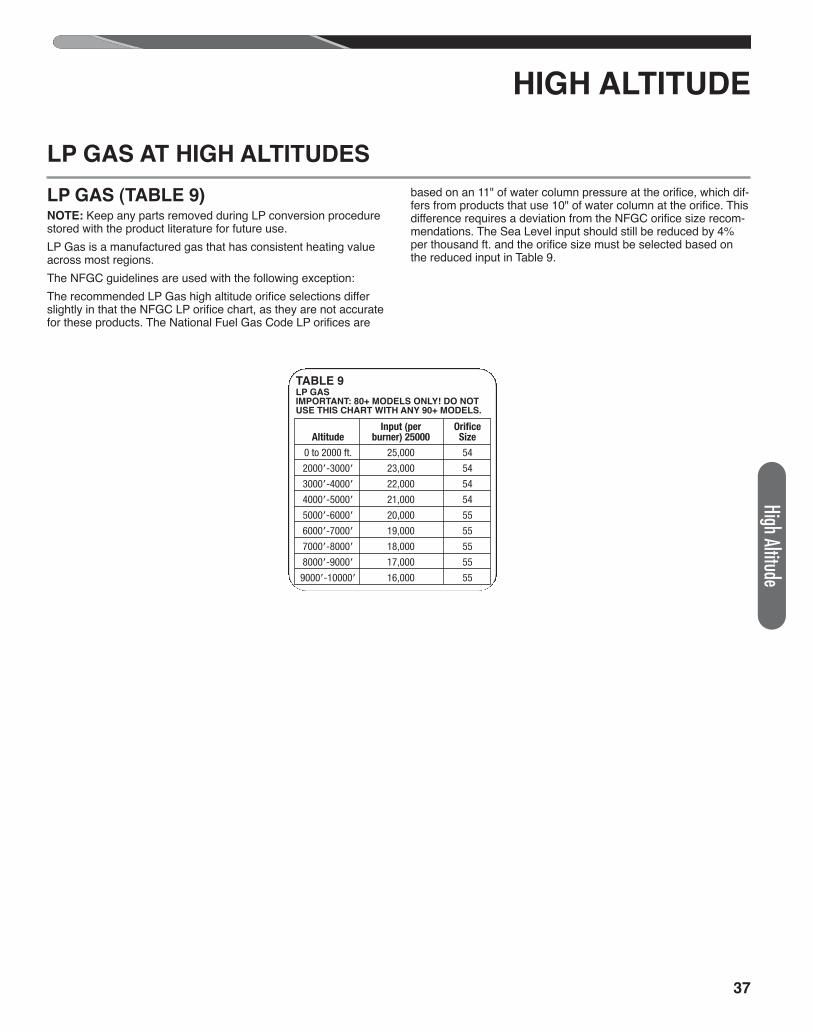
37
HIGH ALTITUDE
LP GAS AT HIGH ALTITUDES
LP GAS (TABLE 9)NOTE: Keep any parts removed during LP conversion procedurestored with the product literature for future use.LP Gas is a manufactured gas that has consistent heating valueacross most regions.The NFGC guidelines are used with the following exception:The recommended LP Gas high altitude orifice selections differslightly in that the NFGC LP orifice chart, as they are not accuratefor these products. The National Fuel Gas Code LP orifices are
based on an 11" of water column pressure at the orifice, which dif-fers from products that use 10" of water column at the orifice. Thisdifference requires a deviation from the NFGC orifice size recom-mendations. The Sea Level input should still be reduced by 4%per thousand ft. and the orifice size must be selected based onthe reduced input in Table 9.
High Altitude
Input (per Orifice Altitude burner) 25000 Size
0 to 2000 ft. 25,000 54
2000�-3000� 23,000 54
3000�-4000� 22,000 54
4000�-5000� 21,000 54
5000�-6000� 20,000 55
6000�-7000� 19,000 55
7000�-8000� 18,000 55
8000�-9000� 17,000 55
9000�-10000� 16,000 55
TABLE 9LP GASIMPORTANT: 80+ MODELS ONLY! DO NOTUSE THIS CHART WITH ANY 90+ MODELS.
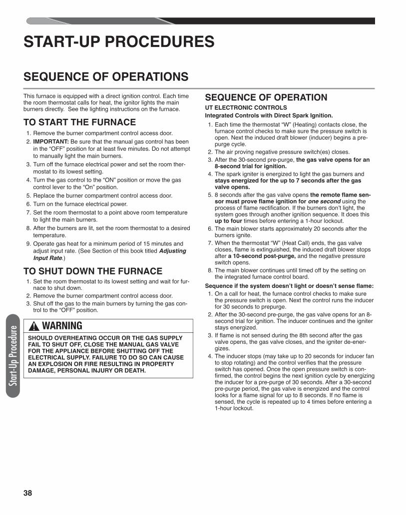
38
Start-
Up Pr
oced
ure
START-UP PROCEDURES
SEQUENCE OF OPERATIONS
This furnace is equipped with a direct ignition control. Each timethe room thermostat calls for heat, the ignitor lights the mainburners directly. See the lighting instructions on the furnace.
TO START THE FURNACE 1. Remove the burner compartment control access door. 2. IMPORTANT: Be sure that the manual gas control has been
in the “OFF” position for at least five minutes. Do not attemptto manually light the main burners.
3. Turn off the furnace electrical power and set the room ther-mostat to its lowest setting.
4. Turn the gas control to the “ON” position or move the gascontrol lever to the “On” position.
5. Replace the burner compartment control access door. 6. Turn on the furnace electrical power. 7. Set the room thermostat to a point above room temperature
to light the main burners. 8. After the burners are lit, set the room thermostat to a desired
temperature. 9. Operate gas heat for a minimum period of 15 minutes and
adjust input rate. (See Section of this book titled Adjusting
Input Rate.)
TO SHUT DOWN THE FURNACE 1. Set the room thermostat to its lowest setting and wait for fur-
nace to shut down. 2. Remove the burner compartment control access door. 3. Shut off the gas to the main burners by turning the gas con-
trol to the “OFF” position.
SEQUENCE OF OPERATIONUT ELECTRONIC CONTROLS
Integrated Controls with Direct Spark Ignition.
1. Each time the thermostat “W” (Heating) contacts close, thefurnace control checks to make sure the pressure switch isopen. Next the induced draft blower (inducer) begins a pre-purge cycle.
2. The air proving negative pressure switch(es) closes. 3. After the 30-second pre-purge, the gas valve opens for an
8-second trial for ignition.
4. The spark igniter is energized to light the gas burners andstays energized for the up to 7 seconds after the gasvalve opens.
5. 8 seconds after the gas valve opens the remote flame sen-sor must prove flame ignition for one second using theprocess of flame rectification. If the burners don’t light, thesystem goes through another ignition sequence. It does thisup to four times before entering a 1-hour lockout.
6. The main blower starts approximately 20 seconds after theburners ignite.
7. When the thermostat “W” (Heat Call) ends, the gas valvecloses, flame is extinguished, the induced draft blower stopsafter a 10-second post-purge, and the negative pressureswitch opens.
8. The main blower continues until timed off by the setting onthe integrated furnace control board.
Sequence if the system doesn’t light or doesn’t sense flame:
1. On a call for heat, the furnace control checks to make surethe pressure switch is open. Next the control runs the inducerfor 30 seconds to prepurge.
2. After the 30-second pre-purge, the gas valve opens for an 8-second trial for ignition. The inducer continues and the igniterstays energized.
3. If flame is not sensed during the 8th second after the gasvalve opens, the gas valve closes, and the igniter de-ener-gizes.
4. The inducer stops (may take up to 20 seconds for inducer fanto stop rotating) and the control verifies that the pressureswitch has opened. Once the open pressure switch is con-firmed, the control begins the next ignition cycle by energizingthe inducer for a pre-purge of 30 seconds. After a 30-secondpre-purge period, the gas valve is energized and the controllooks for a flame signal for up to 8 seconds. If no flame issensed, the cycle is repeated up to 4 times before entering a1-hour lockout.
! WARNINGSHOULD OVERHEATING OCCUR OR THE GAS SUPPLYFAIL TO SHUT OFF, CLOSE THE MANUAL GAS VALVEFOR THE APPLIANCE BEFORE SHUTTING OFF THEELECTRICAL SUPPLY. FAILURE TO DO SO CAN CAUSEAN EXPLOSION OR FIRE RESULTING IN PROPERTYDAMAGE, PERSONAL INJURY OR DEATH.
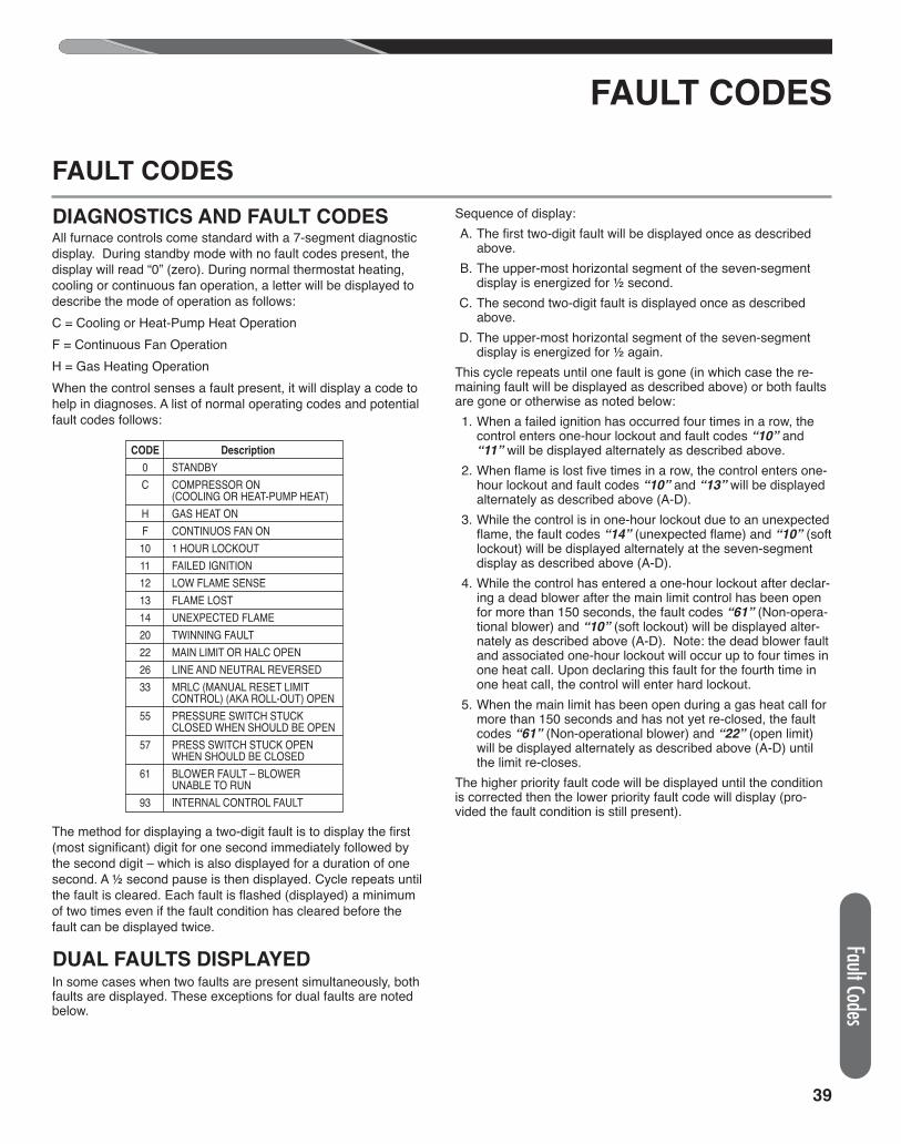
39
Fault Codes
FAULT CODES
FAULT CODES
DIAGNOSTICS AND FAULT CODESAll furnace controls come standard with a 7-segment diagnosticdisplay. During standby mode with no fault codes present, thedisplay will read “0” (zero). During normal thermostat heating,cooling or continuous fan operation, a letter will be displayed todescribe the mode of operation as follows:C = Cooling or Heat-Pump Heat OperationF = Continuous Fan OperationH = Gas Heating OperationWhen the control senses a fault present, it will display a code tohelp in diagnoses. A list of normal operating codes and potentialfault codes follows:
The method for displaying a two-digit fault is to display the first(most significant) digit for one second immediately followed bythe second digit – which is also displayed for a duration of onesecond. A ½ second pause is then displayed. Cycle repeats untilthe fault is cleared. Each fault is flashed (displayed) a minimumof two times even if the fault condition has cleared before thefault can be displayed twice.
DUAL FAULTS DISPLAYEDIn some cases when two faults are present simultaneously, bothfaults are displayed. These exceptions for dual faults are notedbelow.
Sequence of display: A. The first two-digit fault will be displayed once as described
above. B. The upper-most horizontal segment of the seven-segment
display is energized for ½ second. C. The second two-digit fault is displayed once as described
above. D. The upper-most horizontal segment of the seven-segment
display is energized for ½ again.This cycle repeats until one fault is gone (in which case the re-maining fault will be displayed as described above) or both faultsare gone or otherwise as noted below: 1. When a failed ignition has occurred four times in a row, the
control enters one-hour lockout and fault codes “10” and“11” will be displayed alternately as described above.
2. When flame is lost five times in a row, the control enters one-hour lockout and fault codes “10” and “13” will be displayedalternately as described above (A-D).
3. While the control is in one-hour lockout due to an unexpectedflame, the fault codes “14” (unexpected flame) and “10” (softlockout) will be displayed alternately at the seven-segmentdisplay as described above (A-D).
4. While the control has entered a one-hour lockout after declar-ing a dead blower after the main limit control has been openfor more than 150 seconds, the fault codes “61” (Non-opera-tional blower) and “10” (soft lockout) will be displayed alter-nately as described above (A-D). Note: the dead blower faultand associated one-hour lockout will occur up to four times inone heat call. Upon declaring this fault for the fourth time inone heat call, the control will enter hard lockout.
5. When the main limit has been open during a gas heat call formore than 150 seconds and has not yet re-closed, the faultcodes “61” (Non-operational blower) and “22” (open limit)will be displayed alternately as described above (A-D) untilthe limit re-closes.
The higher priority fault code will be displayed until the conditionis corrected then the lower priority fault code will display (pro-vided the fault condition is still present).
CODE Description
0 STANDBYC COMPRESSOR ON
(COOLING OR HEAT-PUMP HEAT)H GAS HEAT ONF CONTINUOS FAN ON10 1 HOUR LOCKOUT11 FAILED IGNITION12 LOW FLAME SENSE13 FLAME LOST14 UNEXPECTED FLAME20 TWINNING FAULT22 MAIN LIMIT OR HALC OPEN26 LINE AND NEUTRAL REVERSED33 MRLC (MANUAL RESET LIMIT
CONTROL) (AKA ROLL-OUT) OPEN55 PRESSURE SWITCH STUCK
CLOSED WHEN SHOULD BE OPEN57 PRESS SWITCH STUCK OPEN
WHEN SHOULD BE CLOSED61 BLOWER FAULT – BLOWER
UNABLE TO RUN93 INTERNAL CONTROL FAULT
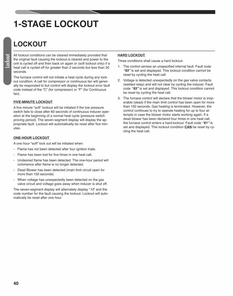
40
Lock
out
1-STAGE LOCKOUT
LOCKOUT
All lockout conditions can be cleared immediately provided thatthe original fault causing the lockout is cleared and power to theunit is cycled off and then back on again or (soft lockout only) if aheat call is cycled off for greater than 2 seconds but less than 20seconds.The furnace control will not initiate a heat cycle during any lock-out condition. A call for compressor or continuous fan will gener-ally be responded to but control will display the lockout error faultcode instead of the “C” (for compressor) or “F” (for Continuousfan).
FIVE-MINUTE LOCKOUT
A five minute “soft” lockout will be initiated if the low pressureswitch fails to close after 60 seconds of continuous inducer oper-ation at the beginning of a normal heat cycle (pressure switchproving period). The seven-segment display will display the ap-propriate fault. Lockout will automatically be reset after five min-utes.
ONE-HOUR LOCKOUT
A one hour “soft” lock out will be initiated when: - Flame has not been detected after four ignition trials.- Flame has been lost for five times in one heat call.- Undesired flame has been detected. The one-hour period will
commence after flame is no longer detected. - Dead Blower has been detected (main limit circuit open for
more than 150 seconds)- When voltage has unexpectedly been detected on the gas
valve circuit and voltage goes away when inducer is shut off.The seven-segment display will alternately display “10” and thecode number for the fault causing the lockout. Lockout will auto-matically be reset after one hour
HARD LOCKOUT
Three conditions shall cause a hard lockout:1. The control senses an unspecified internal fault. Fault code
“93” is set and displayed. This lockout condition cannot bereset by cycling the heat call.
2. Voltage is detected unexpectedly on the gas valve contacts(welded relay) and will not clear by cycling the inducer. Faultcode “93” is set and displayed. This lockout condition cannotbe reset by cycling the heat call.
3. The furnace control will declare that the blower motor is inop-erable (dead) if the main limit control has been open for morethan 150 seconds. Gas heating is terminated. However, thecontrol continues to try to operate heating for up to four at-tempts in case the blower motor starts working again. If adead blower has been declared four times in one heat call,the furnace control enters a hard-lockout. Fault code “61” isset and displayed. This lockout condition CAN be reset by cy-cling the heat call.
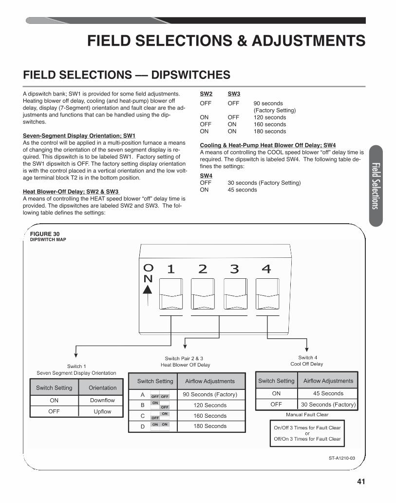
41
Field Selections
FIELD SELECTIONS & ADJUSTMENTS
FIELD SELECTIONS –– DIPSWITCHES
A dipswitch bank; SW1 is provided for some field adjustments.Heating blower off delay, cooling (and heat-pump) blower offdelay, display (7-Segment) orientation and fault clear are the ad-justments and functions that can be handled using the dip-switches.
Seven-Segment Display Orientation; SW1
As the control will be applied in a multi-position furnace a meansof changing the orientation of the seven segment display is re-quired. This dipswitch is to be labeled SW1. Factory setting ofthe SW1 dipswitch is OFF. The factory setting display orientationis with the control placed in a vertical orientation and the low volt-age terminal block T2 is in the bottom position.
Heat Blower-Off Delay; SW2 & SW3
A means of controlling the HEAT speed blower “off” delay time isprovided. The dipswitches are labeled SW2 and SW3. The fol-lowing table defines the settings:
SW2 SW3
OFF OFF 90 seconds(Factory Setting)
ON OFF 120 secondsOFF ON 160 secondsON ON 180 seconds
Cooling & Heat-Pump Heat Blower Off Delay; SW4
A means of controlling the COOL speed blower “off” delay time isrequired. The dipswitch is labeled SW4. The following table de-fines the settings:SW4
OFF 30 seconds (Factory Setting)ON 45 seconds
ST-A1210-03
FIGURE 30DIPSWITCH MAP
42
Field
Selec
tions
FLAME STATUS L.E.D. (AMBER)
A yellow or amber L.E.D. is provided to indicate flame status.When normal flame is sensed, the flame L.E.D. is continuouslyon. The flame L.E.D. will flash at a rate of one to four flashes persecond if a weak flame is detected. If an unexpected flame is de-
tected, the L.E.D. will flash rapidly. The L.E.D. is off when there isno flame detected.For more diagnostics information, consult the wiring diagram anddiagnostics chart at the end of this book.
TIMING DIAGRAM
On the next page is a timing diagram for normal heat sequence.This diagram assumes no faults are present during the heat call.
MANUAL FAULT CLEAR; SW4Faults will automatically be cleared from the fault buffer after oneweek. The fault buffer can also be manually cleared if this is de-sired. For the first 30 seconds after a change in state of dip-switch SW4, the furnace control will wait to determine if the
switch becomes on/off/on/off/on/off or off/on/off/on/off/onwithin 30 seconds. When this action is detected within 30 sec-onds, the fault code memory buffer shall be cleared. Be sure toreturn the dipswitch to the original state (on or off) or is in the de-sired position after clearing the fault buffer using this method.
FAULT RECALL
Upon power reset, the three most recent faults which are lessthan one week old will be flashed in succession from the most re-cent to the oldest. This will be done as a diagnostic aid to the
field technician. After one week, a fault will be removed from thefault buffer.
TIMING DIAGRAM, FIELD SELECTIONS &ADJUSTMENTSFAULT CLEAR
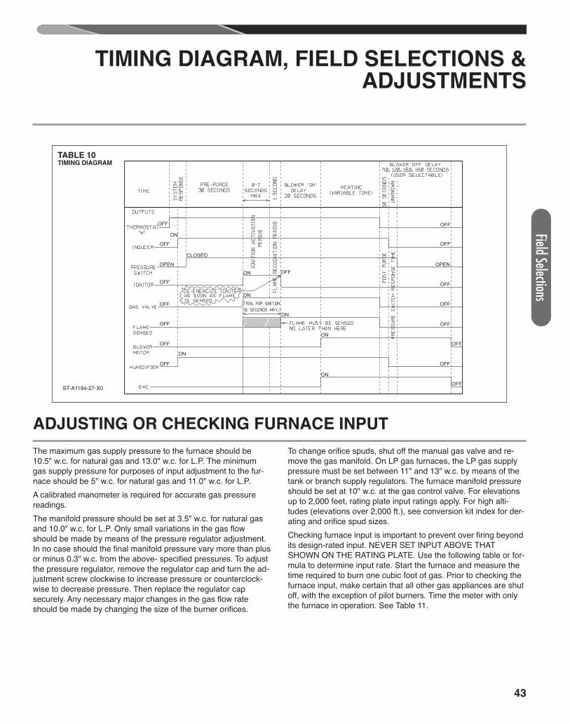
43
ADJUSTING OR CHECKING FURNACE INPUT
The maximum gas supply pressure to the furnace should be10.5" w.c. for natural gas and 13.0" w.c. for L.P. The minimumgas supply pressure for purposes of input adjustment to the fur-nace should be 5" w.c. for natural gas and 11.0" w.c. for L.P.A calibrated manometer is required for accurate gas pressurereadings.The manifold pressure should be set at 3.5" w.c. for natural gasand 10.0" w.c. for L.P. Only small variations in the gas flowshould be made by means of the pressure regulator adjustment.In no case should the final manifold pressure vary more than plusor minus 0.3" w.c. from the above- specified pressures. To adjustthe pressure regulator, remove the regulator cap and turn the ad-justment screw clockwise to increase pressure or counterclock-wise to decrease pressure. Then replace the regulator capsecurely. Any necessary major changes in the gas flow rateshould be made by changing the size of the burner orifices.
To change orifice spuds, shut off the manual gas valve and re-move the gas manifold. On LP gas furnaces, the LP gas supplypressure must be set between 11" and 13" w.c. by means of thetank or branch supply regulators. The furnace manifold pressureshould be set at 10" w.c. at the gas control valve. For elevationsup to 2,000 feet, rating plate input ratings apply. For high alti-tudes (elevations over 2,000 ft.), see conversion kit index for der-ating and orifice spud sizes.Checking furnace input is important to prevent over firing beyondits design-rated input. NEVER SET INPUT ABOVE THATSHOWN ON THE RATING PLATE. Use the following table or for-mula to determine input rate. Start the furnace and measure thetime required to burn one cubic foot of gas. Prior to checking thefurnace input, make certain that all other gas appliances are shutoff, with the exception of pilot burners. Time the meter with onlythe furnace in operation. See Table 11.
TABLE 10TIMING DIAGRAM
ST-A1194-27-X0
OFF
OFF
OFF
OFF
OFF
OFF
OFF
OFF
OFF
OFF
OFF
OFF
OFF
OPEN
OFF
OFF
CLOSED
OPEN
ON
ON
ON
ON
ON
ON OFF
ON
TIMING DIAGRAM, FIELD SELECTIONS &ADJUSTMENTS
Field Selections
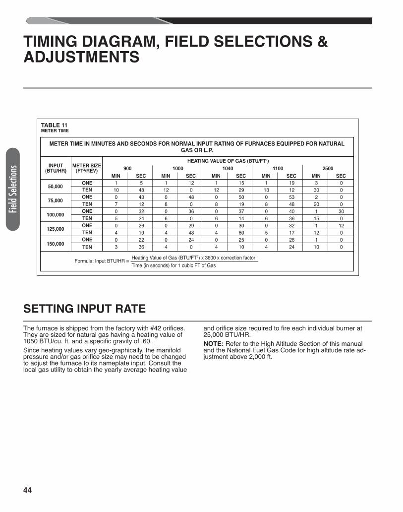
44
SETTING INPUT RATE
The furnace is shipped from the factory with #42 orifices.They are sized for natural gas having a heating value of1050 BTU/cu. ft. and a specific gravity of .60.Since heating values vary geo-graphically, the manifoldpressure and/or gas orifice size may need to be changedto adjust the furnace to its nameplate input. Consult thelocal gas utility to obtain the yearly average heating value
and orifice size required to fire each individual burner at25,000 BTU/HR.NOTE: Refer to the High Altitude Section of this manualand the National Fuel Gas Code for high altitude rate ad-justment above 2,000 ft.
TIMING DIAGRAM, FIELD SELECTIONS &ADJUSTMENTS
Field
Selec
tions
TABLE 11METER TIME
METER TIME IN MINUTES AND SECONDS FOR NORMAL INPUT RATING OF FURNACES EQUIPPED FOR NATURALGAS OR L.P.
INPUT(BTU/HR)
50,000
75,000
100,000
125,000
150,000
ONE
TEN
ONE
TEN
ONE
TEN
ONE
TEN
ONE
TEN
Formula: Input BTU/HR = Heating Value of Gas (BTU/FT3) x 3600 x correction factorFormula: Input BTU/HR = Time (in seconds) for 1 cubic FT of Gas
METER SIZE(FT3/REV)
HEATING VALUE OF GAS (BTU/FT3)
900 1000 1040 1100 2500
MIN SEC MIN SEC MIN SEC MIN SEC MIN SEC
1 5 1 12 1 15 1 19 3 0 10 48 12 0 12 29 13 12 30 0 0 43 0 48 0 50 0 53 2 0 7 12 8 0 8 19 8 48 20 0 0 32 0 36 0 37 0 40 1 30 5 24 6 0 6 14 6 36 15 0 0 26 0 29 0 30 0 32 1 12 4 19 4 48 4 60 5 17 12 0 0 22 0 24 0 25 0 26 1 0 3 36 4 0 4 10 4 24 10 0
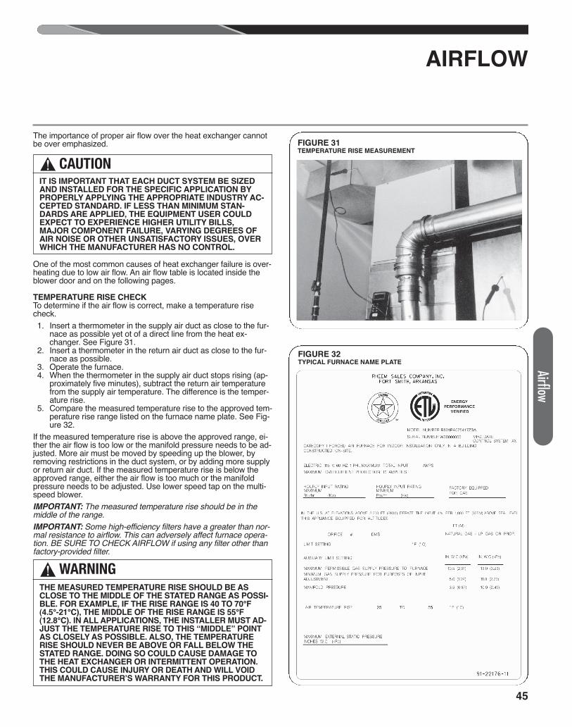
Airflow
AIRFLOW
The importance of proper air flow over the heat exchanger cannotbe over emphasized.
One of the most common causes of heat exchanger failure is over-heating due to low air flow. An air flow table is located inside theblower door and on the following pages.
TEMPERATURE RISE CHECKTo determine if the air flow is correct, make a temperature risecheck. 1. Insert a thermometer in the supply air duct as close to the fur-
nace as possible yet ot of a direct line from the heat ex-changer. See Figure 31.
2. Insert a thermometer in the return air duct as close to the fur-nace as possible.
3. Operate the furnace. 4. When the thermometer in the supply air duct stops rising (ap-
proximately five minutes), subtract the return air temperaturefrom the supply air temperature. The difference is the temper-ature rise.
5. Compare the measured temperature rise to the approved tem-perature rise range listed on the furnace name plate. See Fig-ure 32.
If the measured temperature rise is above the approved range, ei-ther the air flow is too low or the manifold pressure needs to be ad-justed. More air must be moved by speeding up the blower, byremoving restrictions in the duct system, or by adding more supplyor return air duct. If the measured temperature rise is below theapproved range, either the air flow is too much or the manifoldpressure needs to be adjusted. Use lower speed tap on the multi-speed blower.IMPORTANT: The measured temperature rise should be in themiddle of the range.IMPORTANT: Some high-efficiency filters have a greater than nor-mal resistance to airflow. This can adversely affect furnace opera-tion. BE SURE TO CHECK AIRFLOW if using any filter other thanfactory-provided filter.
! CAUTIONIT IS IMPORTANT THAT EACH DUCT SYSTEM BE SIZEDAND INSTALLED FOR THE SPECIFIC APPLICATION BYPROPERLY APPLYING THE APPROPRIATE INDUSTRY AC-CEPTED STANDARD. IF LESS THAN MINIMUM STAN-DARDS ARE APPLIED, THE EQUIPMENT USER COULDEXPECT TO EXPERIENCE HIGHER UTILITY BILLS,MAJOR COMPONENT FAILURE, VARYING DEGREES OFAIR NOISE OR OTHER UNSATISFACTORY ISSUES, OVERWHICH THE MANUFACTURER HAS NO CONTROL.
FIGURE 31TEMPERATURE RISE MEASUREMENT
! WARNINGTHE MEASURED TEMPERATURE RISE SHOULD BE ASCLOSE TO THE MIDDLE OF THE STATED RANGE AS POSSI-BLE. FOR EXAMPLE, IF THE RISE RANGE IS 40 TO 70°F(4.5°-21°C), THE MIDDLE OF THE RISE RANGE IS 55°F(12.8°C). IN ALL APPLICATIONS, THE INSTALLER MUST AD-JUST THE TEMPERATURE RISE TO THIS “MIDDLE” POINTAS CLOSELY AS POSSIBLE. ALSO, THE TEMPERATURERISE SHOULD NEVER BE ABOVE OR FALL BELOW THESTATED RANGE. DOING SO COULD CAUSE DAMAGE TOTHE HEAT EXCHANGER OR INTERMITTENT OPERATION.THIS COULD CAUSE INJURY OR DEATH AND WILL VOIDTHE MANUFACTURER’S WARRANTY FOR THIS PRODUCT.
45
FIGURE 32TYPICAL FURNACE NAME PLATE
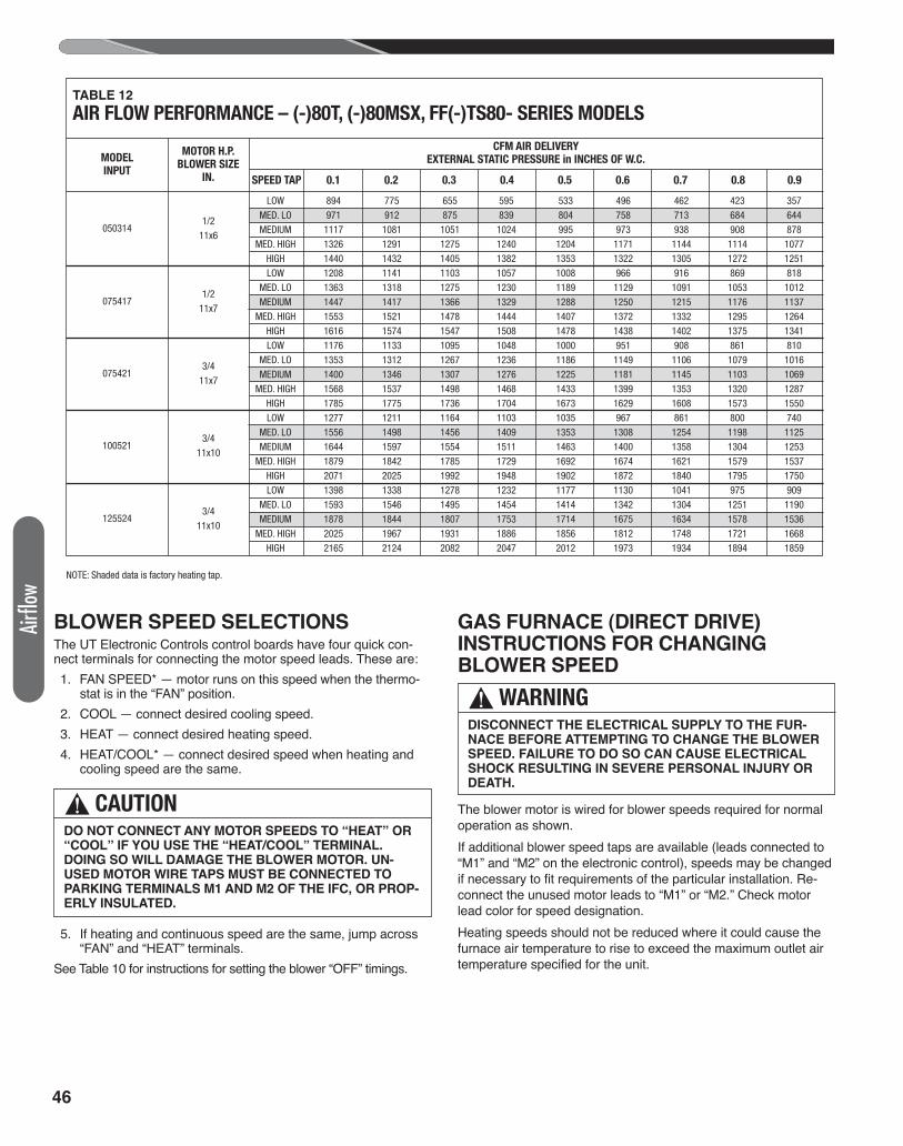
46
BLOWER SPEED SELECTIONSThe UT Electronic Controls control boards have four quick con-nect terminals for connecting the motor speed leads. These are: 1. FAN SPEED* — motor runs on this speed when the thermo-
stat is in the “FAN” position. 2. COOL — connect desired cooling speed. 3. HEAT — connect desired heating speed. 4. HEAT/COOL* — connect desired speed when heating and
cooling speed are the same.
5. If heating and continuous speed are the same, jump across“FAN” and “HEAT” terminals.
See Table 10 for instructions for setting the blower “OFF” timings.
GAS FURNACE (DIRECT DRIVE) INSTRUCTIONS FOR CHANGINGBLOWER SPEED
The blower motor is wired for blower speeds required for normaloperation as shown.If additional blower speed taps are available (leads connected to“M1” and “M2” on the electronic control), speeds may be changedif necessary to fit requirements of the particular installation. Re-connect the unused motor leads to “M1” or “M2.” Check motorlead color for speed designation.Heating speeds should not be reduced where it could cause thefurnace air temperature to rise to exceed the maximum outlet airtemperature specified for the unit.
! CAUTIONDO NOT CONNECT ANY MOTOR SPEEDS TO “HEAT” OR“COOL” IF YOU USE THE “HEAT/COOL” TERMINAL.DOING SO WILL DAMAGE THE BLOWER MOTOR. UN-USED MOTOR WIRE TAPS MUST BE CONNECTED TOPARKING TERMINALS M1 AND M2 OF THE IFC, OR PROP-ERLY INSULATED.
! WARNINGDISCONNECT THE ELECTRICAL SUPPLY TO THE FUR-NACE BEFORE ATTEMPTING TO CHANGE THE BLOWERSPEED. FAILURE TO DO SO CAN CAUSE ELECTRICALSHOCK RESULTING IN SEVERE PERSONAL INJURY ORDEATH.
LOW 894 775 655 595 533 496 462 423 357 MED. LO 971 912 875 839 804 758 713 684 644 MEDIUM 1117 1081 1051 1024 995 973 938 908 878 MED. HIGH 1326 1291 1275 1240 1204 1171 1144 1114 1077 HIGH 1440 1432 1405 1382 1353 1322 1305 1272 1251 LOW 1208 1141 1103 1057 1008 966 916 869 818 MED. LO 1363 1318 1275 1230 1189 1129 1091 1053 1012 MEDIUM 1447 1417 1366 1329 1288 1250 1215 1176 1137 MED. HIGH 1553 1521 1478 1444 1407 1372 1332 1295 1264 HIGH 1616 1574 1547 1508 1478 1438 1402 1375 1341 LOW 1176 1133 1095 1048 1000 951 908 861 810 MED. LO 1353 1312 1267 1236 1186 1149 1106 1079 1016 MEDIUM 1400 1346 1307 1276 1225 1181 1145 1103 1069 MED. HIGH 1568 1537 1498 1468 1433 1399 1353 1320 1287 HIGH 1785 1775 1736 1704 1673 1629 1608 1573 1550 LOW 1277 1211 1164 1103 1035 967 861 800 740 MED. LO 1556 1498 1456 1409 1353 1308 1254 1198 1125 MEDIUM 1644 1597 1554 1511 1463 1400 1358 1304 1253 MED. HIGH 1879 1842 1785 1729 1692 1674 1621 1579 1537 HIGH 2071 2025 1992 1948 1902 1872 1840 1795 1750 LOW 1398 1338 1278 1232 1177 1130 1041 975 909 MED. LO 1593 1546 1495 1454 1414 1342 1304 1251 1190 MEDIUM 1878 1844 1807 1753 1714 1675 1634 1578 1536 MED. HIGH 2025 1967 1931 1886 1856 1812 1748 1721 1668 HIGH 2165 2124 2082 2047 2012 1973 1934 1894 1859
TABLE 12
AIR FLOW PERFORMANCE – (-)80T, (-)80MSX, FF(-)TS80- SERIES MODELS
MODELINPUT
MOTOR H.P.BLOWER SIZE
IN.
CFM AIR DELIVERYEXTERNAL STATIC PRESSURE in INCHES OF W.C.
SPEED TAP 0.1 0.2 0.3 0.4 0.5 0.6 0.7 0.8 0.9
0503141/2
11x6
075417
075421
100521
125524
1/211x7
3/411x7
3/411x10
3/411x10
NOTE: Shaded data is factory heating tap.
Airflo
w
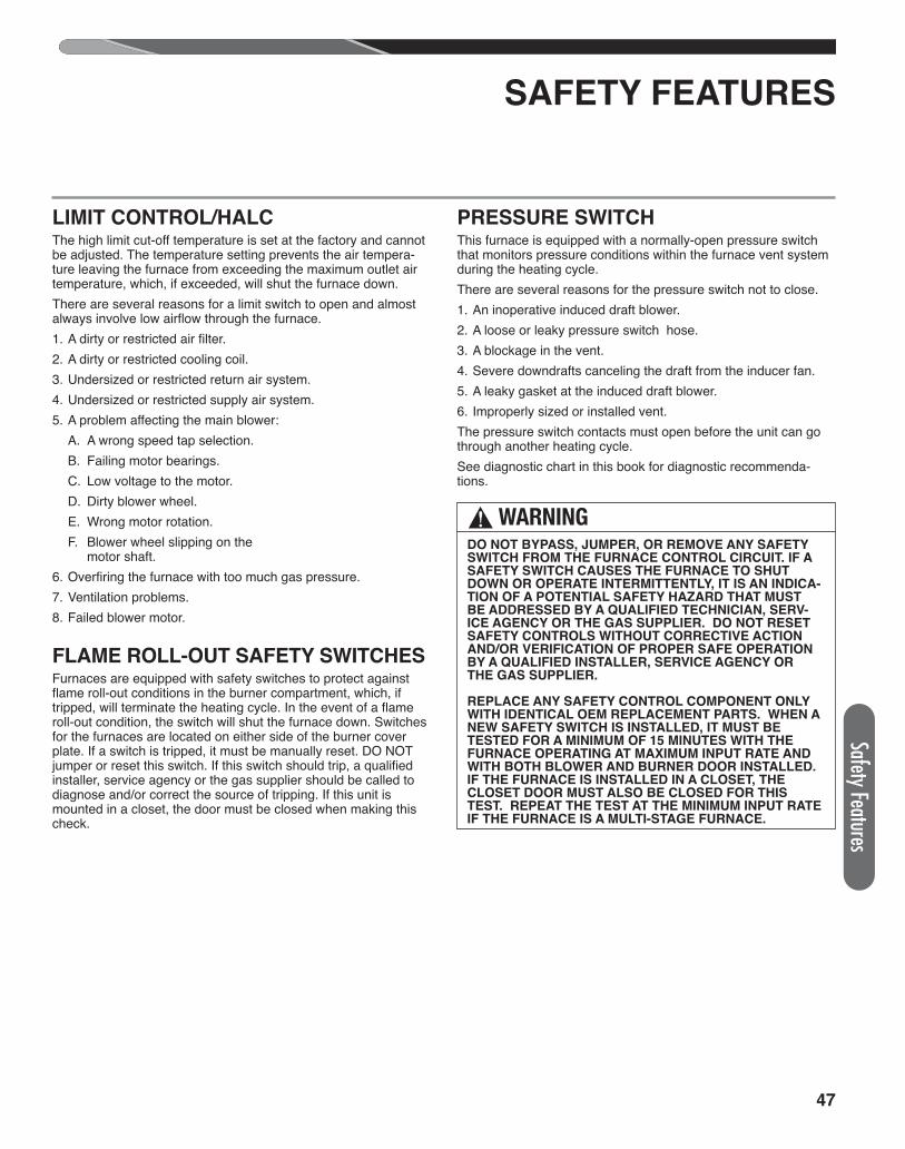
47
Safety Features
SAFETY FEATURES
LIMIT CONTROL/HALCThe high limit cut-off temperature is set at the factory and cannotbe adjusted. The temperature setting prevents the air tempera-ture leaving the furnace from exceeding the maximum outlet airtemperature, which, if exceeded, will shut the furnace down. There are several reasons for a limit switch to open and almostalways involve low airflow through the furnace.1. A dirty or restricted air filter.2. A dirty or restricted cooling coil.3. Undersized or restricted return air system.4. Undersized or restricted supply air system.5. A problem affecting the main blower:
A. A wrong speed tap selection.B. Failing motor bearings.C. Low voltage to the motor.D. Dirty blower wheel.E. Wrong motor rotation.F. Blower wheel slipping on theF. motor shaft.
6. Overfiring the furnace with too much gas pressure.7. Ventilation problems.8. Failed blower motor.
FLAME ROLL-OUT SAFETY SWITCHESFurnaces are equipped with safety switches to protect againstflame roll-out conditions in the burner compartment, which, iftripped, will terminate the heating cycle. In the event of a flameroll-out condition, the switch will shut the furnace down. Switchesfor the furnaces are located on either side of the burner coverplate. If a switch is tripped, it must be manually reset. DO NOTjumper or reset this switch. If this switch should trip, a qualifiedinstaller, service agency or the gas supplier should be called todiagnose and/or correct the source of tripping. If this unit ismounted in a closet, the door must be closed when making thischeck.
PRESSURE SWITCHThis furnace is equipped with a normally-open pressure switchthat monitors pressure conditions within the furnace vent systemduring the heating cycle.There are several reasons for the pressure switch not to close.1. An inoperative induced draft blower.2. A loose or leaky pressure switch hose.3. A blockage in the vent.4. Severe downdrafts canceling the draft from the inducer fan.5. A leaky gasket at the induced draft blower.6. Improperly sized or installed vent.The pressure switch contacts must open before the unit can gothrough another heating cycle.See diagnostic chart in this book for diagnostic recommenda-tions.
! WARNINGDO NOT BYPASS, JUMPER, OR REMOVE ANY SAFETYSWITCH FROM THE FURNACE CONTROL CIRCUIT. IF ASAFETY SWITCH CAUSES THE FURNACE TO SHUTDOWN OR OPERATE INTERMITTENTLY, IT IS AN INDICA-TION OF A POTENTIAL SAFETY HAZARD THAT MUSTBE ADDRESSED BY A QUALIFIED TECHNICIAN, SERV-ICE AGENCY OR THE GAS SUPPLIER. DO NOT RESETSAFETY CONTROLS WITHOUT CORRECTIVE ACTIONAND/OR VERIFICATION OF PROPER SAFE OPERATIONBY A QUALIFIED INSTALLER, SERVICE AGENCY ORTHE GAS SUPPLIER.
REPLACE ANY SAFETY CONTROL COMPONENT ONLYWITH IDENTICAL OEM REPLACEMENT PARTS. WHEN ANEW SAFETY SWITCH IS INSTALLED, IT MUST BETESTED FOR A MINIMUM OF 15 MINUTES WITH THEFURNACE OPERATING AT MAXIMUM INPUT RATE ANDWITH BOTH BLOWER AND BURNER DOOR INSTALLED.IF THE FURNACE IS INSTALLED IN A CLOSET, THECLOSET DOOR MUST ALSO BE CLOSED FOR THISTEST. REPEAT THE TEST AT THE MINIMUM INPUT RATEIF THE FURNACE IS A MULTI-STAGE FURNACE.
48
Maint
enan
ce
MAINTENANCE
MAINTENANCE
FILTERS
LUBRICATION
IMPORTANT: DO NOT attempt to lubricate the bearingson the blower motor or the induced draft blower motor. Ad-dition of lubricants can reduce the motor life and void thewarranty.The blower motor and induced draft blower motor are per-manently lubricated by the manufacturer and do not re-quire further attention.It is recommended that the blower motor and induced draftblower motor be cleaned periodically by a qualified in-staller, service agency, or the gas supplier to prevent the
possibility of overheating due to an accumulation of dustand dirt on the windings or on the motor exterior. And, assuggested elsewhere in these instructions, the air filtersshould be kept clean. Dirty filters can restrict airflow. Themotor depends upon sufficient air flowing across andthrough it to keep from overheating.
! CAUTIONDO NOT OPERATE THE SYSTEM FOR EXTENDED PE-RIODS WITHOUT FILTERS. A PORTION OF THE DUSTENTRAINED IN THE AIR MAY TEMPORARILY LODGEIN THE AIR DUCT RUNS AND AT THE SUPPLY REGIS-TERS. ANY RECIRCULATED DUST PARTICLES WILL
BE HEATED AND CHARRED BY CONTACT WITH THEFURNACE HEAT EXCHANGER. THIS RESIDUE WILLSOIL CEILINGS, WALLS, DRAPES, CARPETS ANDOTHER HOUSEHOLD ARTICLES.
! WARNINGTHESE INSTRUCTIONS ARE INTENDED AS AN AID TOQUALIFIED SERVICE PERSONNEL FOR PROPER IN-STALLATION, ADJUSTMENT AND OPERATION OF THISUNIT. READ THESE INSTRUCTIONS THOROUGHLY BE-FORE ATTEMPTING INSTALLATION OR OPERATION.FAILURE TO FOLLOW THESE INSTRUCTIONS MAY RE-SULT IN IMPROPER INSTALLATION, ADJUSTMENT,SERVICE OR MAINTENANCE, POSSIBLY RESULTING IN
FIRE, ELECTRICAL SHOCK, CARBON MONOXIDE POI-SONING, EXPLOSION, PROPERTY DAMAGE, PER-SONAL INJURY OR DEATH.
DISCONNECT MAIN ELECTRICAL POWER TO THEUNIT BEFORE ATTEMPTING ANY MAINTENANCE.FAILURE TO DO SO CAN CAUSE ELECTRICALSHOCK RESULTING IN PERSONAL INJURY ORDEATH.
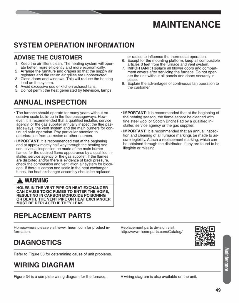
49
ANNUAL INSPECTION
MAINTENANCE
• The furnace should operate for many years without ex-cessive scale build-up in the flue passageways. How-ever, it is recommended that a qualified installer, serviceagency, or the gas supplier annually inspect the flue pas-sageways, the vent system and the main burners for con-tinued safe operation. Pay particular attention todeterioration from corrosion or other sources.
• IMPORTANT: It is recommended that at the beginningand at approximately half way through the heating sea-son, a visual inspection be made of the main burnerflames for the desired flame appearance by a qualified in-staller, service agency or the gas supplier. If the flamesare distorted and/or there is evidence of back pressure,check the combustion and ventilation air system for block-age. If there is carbon and scale in the heat exchangertubes, the heat exchanger assembly should be replaced.
• IMPORTANT: It is recommended that at the beginning ofthe heating season, the flame sensor be cleaned withfine steel wool or Scotch Bright Pad by a qualified in-staller, service agency or the gas supplier.
• IMPORTANT: It is recommended that an annual inspec-tion and cleaning of all furnace markings be made to as-sure legibility. Attach a replacement marking, which canbe obtained through the distributor, if any are found to beillegible or missing.
REPLACEMENT PARTS
Homeowners please visit www.rheem.com for product in-formation.
Replacement parts division visithttp://www.rheemparts.com/Catalog/
DIAGNOSTICS
Refer to Figure 33 for determining cause of unit problems.
WIRING DIAGRAM
Figure 34 is a complete wiring diagram for the furnace. A wiring diagram is also available on the unit.
SYSTEM OPERATION INFORMATION
ADVISE THE CUSTOMER 1. Keep the air filters clean. The heating system will oper-
ate better, more efficiently and more economically. 2. Arrange the furniture and drapes so that the supply air
registers and the return air grilles are unobstructed. 3. Close doors and windows. This will reduce the heating
load on the system. 4. Avoid excessive use of kitchen exhaust fans. 5. Do not permit the heat generated by television, lamps
or radios to influence the thermostat operation. 6. Except for the mounting platform, keep all combustible
articles 3 feet from the furnace and vent system. 7. IMPORTANT: Replace all blower doors and compart-
ment covers after servicing the furnace. Do not oper-ate the unit without all panels and doors securely inplace.
8. Explain the advantages of continuous fan operation tothe customer.
! WARNINGHOLES IN THE VENT PIPE OR HEAT EXCHANGERCAN CAUSE TOXIC FUMES TO ENTER THE HOME,RESULTING IN CARBON MONOXIDE POISONINGOR DEATH. THE VENT PIPE OR HEAT EXCHANGERMUST BE REPLACED IF THEY LEAK.
Maintenance
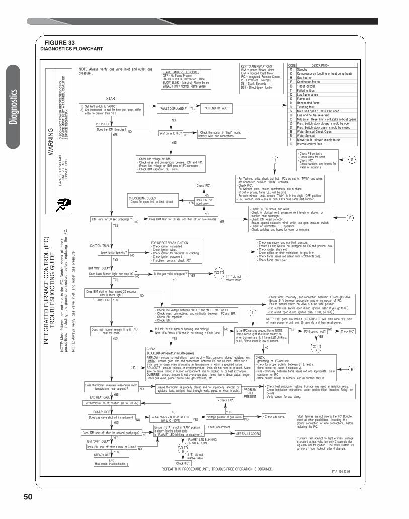
50
Diag
nosti
cs
FIGURE 33DIAGNOSTICS FLOWCHART
GO TOE
NOTE: Always verify gas valve inlet and outlet gaspressure .
KEY TO ABBREVIATIONSIBM = Indoor Blower MotorIDM = Induced Draft MotorIFC = Integrated Furnace ControlPS = Pressure Switch(es)SE = Spark ElectrodeDSI = Direct-Spark Ignition
FLAME (AMBER) LED CODESOFF = No Flame Presen tRAPID BLINK = Unexpected FlameSLOW BLINK = Marginal Flame SenseSTEADY ON = Normal Flame Sense
1) Set FAN switch to “AUTO ”2) Set thermostat to call for heat (set temp. differ-
ential to greater than 10 F
Does the IDM Energize?
IDM Runs for 30 sec. pre-purge ?
Spark Ignitor Sparking?
Does Main Burner Light and stay lit? Is the gas valve energized?
PS dropping out ? Check IFC*
Does IBM start on heat speed 20 secondsafter burners light ?
Does main burner remain lit untilheat call ends?
Does thermostat maintain reasonable room temperature near setpoint ?
Set thermostat to off position (W to C = ØV)
Does gas valve shut off immediately?
Does IDM shut off after ten second post-purge?
Does IBM shut off after a max. of 3 min?
ENDHeat-mode troubleshootin g
“FAULT DISPLAYED ?”
24V on W to IFC?
Check IFC*.
Does IDM runindefinately .
Does IDM Run for 60 sec. and then off for Five minutes
- Check thermostat in “heat” mode,batte ry, wire, and connections.
- Check PS contact s- Check wires for short.- Check IFC*.- Check switches and hoses for
water or moistur e
- For Twinned units, check that both IFCs are set for “TWIN” and wire sare connected between “TWIN” terminals .
- Check IFC*.- For twinned units, ensure transformers are in phase.
(if out of phase, flame LED will be dim) .- For non-twinned units, ensure “TWIN” is in the single (OFF) position.- For Twinned units – ensure both IFC‘s have same part number .
- Check PS, PS Hoses, and wires.- Check for blocked vent, excessive vent length or elbows, or
blocked heat exchanger .- Check IDM wired correctly .- Ensure against excessive wind, which can open pressure switch.- Check for intermittent P.S. operation.- Check switches and hoses for water or moisture.
- Check gas supply and manifold pressure.- Ensure L1 and Neutral not swapped on IFC and junction box.- Check igniter alignment .- Check orifice or other restrictions to gas flo w.- Check flame sense rod (clean with scotch brite pad).- Check flame carry over.
- Check wires, continuity , and connection between IFC and gas valve.- Ensure 24 V between appropriate pins on connector of IFC.
Ensure manual switch on valve is in the “ON” position.- Did a pressure switch open during ignition trial? If yes, go to F- Did a limit open during ignition trial? If yes, go to D- Check line voltage between “HEAT” and “NEUTRAL” on IFC.
- Check wires, connections, and continuity between IFC and IBM.- Check IBM capacitor .- Check IBM.
CHECK:- grounding on IFC and unit.- check for proper polarity between L1 & neutral.- flame sense rod (clean if necessar y).- wire continually between flame sense rod and appropriate pin of
connector on IFC- flame carries across all burners, and all burners stay lit.
CHECK:
AIRFLOW - ensure no restrictions, such as dirty filte r, dampers, closed registers, etc.LIMITS - ensure good wire and connections between IFC and all limits. Make sur elimits are not open when cir culating air temperature is within a specified range.ROLLOUTS - ensure rollouts or overtemperature limits do not need to be reset. Makesure no flame rollout in burner compartment due to blocked flu or heat exchanger .OVERFIRE - ensure furnace is not overtemperature (temp rise is above stated range) .Check gas valve, proper orifice size, gas pressure, etc.
Is Limit cir cuit open or opening and closing?Note: IFC Status LED should be blinking a Fault Code. Is the IFC sensing a good flame: NOTE:
Flame sense light should be steady-onwhen burners are lit. If flame LED blinking,or off, flame sense is low or absent.
Ensure thermostat is properly placed and not improperly affected byregisters, fans, sunlight, heat through walls, pipes, or wires in walls .
- Check heat anticipator setting. Furnace may need an isolation relay.- Check installation instructions under section titled “Isolation Relay” for
details .- Verify correct furnace sizing.
NOTE: If IFC goes into lockout (“ST ATUS LED will blink code “1”), shutoff main power to unit, wait 30 seconds and then reset power .
PROBLEMSTILL
PRESENT
Fault Code Present
“FLAME” LED BLINKINGOR STEADY ON
If “E” did notresolve issue
Double check - Is W off at IFC?(W to C = ØV?)
Voltage present at gas valve? - Check gas valve.
SEE FAULT CODES
- Check IFC*.
Check IFC*.
*Most failures are not due to the IFC. Doubl echeck all other possibilities, including theground connection or wire connections, beforereplacing the IFC.Ensure TSTAT is not in “FAN” position.
Is disply flashing a fault codeIs “FLAME” LED blinking or steady-on ?
**System will attempt to light 4 times. Voltageis present at gas valve for only 7 seconds dur -ing each trial for ignition. The entire system willgo into a 1 hour lockout after 4 attempts.
- Check line voltage at IDM.- Check wires and connections between IDM and IFC.- Ensure line voltage on IDM pins of IFC connector .- Check IDM capacitor (90+ only) .
CHECK BLINK CODES- Check for open limit or limit cir cuit.
FOR DIRECT SPARK IGNITION - Check ignitor connected .- Check ignitor wires.- Check ignitor for fractures or cracking- Check ignitor placement .- If problem persists, check IFC*.
START
REPEAT THIS PROCEDURE UNTIL TROUBLE-FREE OPERATION IS OBTAINED.
YES
NO
NO
If “ I ” did notresolve issue.
NO NO
NO
NO
NO
NO
NONO
NO
NO
NO
NO
NO
NO
NO
NO
YES
YESYES
YES
YES
YES
YES
YES
YES
YES
YES YES
YES
YES
YES
YES
YES
I
D
F
H
E
G
YES
NO
YES
PREPURGE
IGNITION TRIAL
IBM “ON” DELAY
STEADY HEAT
END HEAT CALL
POST-PURGE
IBM “OFF” DELAY
STEADY OFF
NO
**
ST-A1194-23-03
GO TOF
GO TOI
WAR
NING
HAZA
RDO
US V
OLT
AGE
LINE
VO
LTAG
ECO
NNEC
TIO
NS
DISC
ONN
ECT
POW
ER B
EFO
RE S
ERVI
CING
.SE
RVIC
E M
UST
BE B
Y A
TRAI
NED,
QUA
LIFI
EDSE
RVIC
E TE
CHNI
CIAN
.
NOTE
:Alw
ays
verif
y ga
s va
lve i
nlet
and
out
let
gas
pres
sure
.
INTE
GRA
TED
FURN
ACE
CONT
ROL
(IFC)
TRO
UBLE
SHO
OTI
NG G
UIDE
NOTE
: Mos
t fa
ilure
s ar
e no
t du
e to
the
IFC.
Dou
ble
chec
k al
l ot
her
poss
ibilit
ies,
in
cludi
ng
the
grou
nd c
onne
ctio
n,
befo
re r
epla
cing
the
IFC.
“ATTEND TO FAULT”
CODE DESCRIPTIONOCHF101112131420222633555758596193
StandbyCompressor on (cooling or heat pump heat)Gas heat onContinuous fan on1 hour lockoutFailed ignitionLow flame senseFlame lostUnexpected flameTwinning faultMain limit open / HALC limit openLine and neutral reversedMrlc (man. Reset limit cont.)(aka roll-out open)Pres. Switch stuck closed, should be openPres. Switch stuck open, should be closedWater Sensed Circuit OpenWater SensedBlower fault - blower unable to runInternal control fault
BLOCKED DRAIN - (fault “59” should be present)
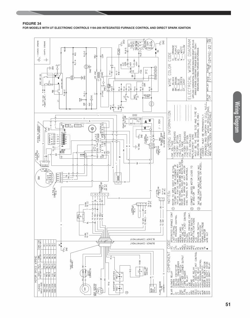
51
Wiring DiagramFIGURE 34FOR MODELS WITH UT ELECTRONIC CONTROLS 1194-200 INTEGRATED FURNACE CONTROL AND DIRECT SPARK IGNITION
UP
FLO
W /
HO
RIZ
ON
TAL,
BLO
WE
R IN
DU
CE
D D
RA
FT, 8
0 P
LUS
S
ING
LE S
TAG
E, C
ON
STA
NT
TOR
QU
E S
ELE
CT
- TE
CH
/ E
ND
UR
A G
AS
FIR
ED
, FO
RC
ED
AIR
FU
RN
AC
E.
INP
UT
/ SIZ
E50
K /
14W
75K
/ 17
W75
K /
21W
100K
/ 21
W12
5K /
24W
03

52 CM 0217