Embed Size (px)
Citation preview

SECURITY ENERGIZER
Installation and User Manual
28
JVA ELECTRIC FENCE SYSTEMSEdition 2.3, July 2019

JVA
Z E
nerg
izer
Ran
ge C
once
pt
Thank you for choosing our product. The JVA brand is a range of electric fencing products carefully selected from leading manufacturers around the world to meet the needs of perimeter security.
THE JVA Z RANGE ENERGIZER CONCEPTThe JVA Range of Energizers has been collaboratively designed and manufactured by an international team with over 30 years of electric fence experience earned in some of the most testing security environments in the world. It aims to provide the very best low-cost, high-voltage security energizers in the world. They are compact, integrated and fully programmable electric fence energizers with built-in alarm units and LCD out and return voltage display. They also have the option of being controlled from a remote LCD keypad.
State-of-the-art energizer design IP4 x and ABS plastic
Unique LCD display depicting fence out and return voltage
Wall-mountable, robust energizer housing with easily detachable PCB chassis for ease of installation and repair
Unique LCD keypad option depicting fence and alarm condition
TWO-YEAR WARRANTYAll JVA products carry a 2-year warranty against defective
components and workmanship. The warranty excludes damage caused by acts of Nature such as lightning or flooding, power
supply surges, rough handling, malicious action or incorrect wiring.
Please retain your invoice as proof of purchase and fill in the warranty form on page 39.
2-yrWARRANTY
JVA ELECTRIC FENCE SYSTEMS

1
JVA ELECTRIC FENCE SYSTEMS JVA ELECTRIC FENCE SYSTEMSC
ontents
1. INTRODUCTION ...................................................................................... 3
2. FEATURES ............................................................................................... 42.1 Power .............................................................................................. 42.2 Control / Monitoring ......................................................................... 42.3 Safety .............................................................................................. 42.4 Reliability ......................................................................................... 4
3. SPECIFICATIONS .................................................................................... 5
4. DESCRIPTION ......................................................................................... 64.1 JVA Z28 Exterior .............................................................................. 64.2 JVA Z28 – High Voltage Terminals .................................................. 64.3 LCD Voltage Display ........................................................................ 74.4 Status LED Lights ............................................................................ 84.5 Inputs and Outputs .......................................................................... 8
4.5.1 Relay Functions ................................................................... 94.6 4-line LCD Keypad .......................................................................... 104.7 Internal Beeper / Keypad Beeper .................................................... 224.8 Cabling ............................................................................................ 224.9 Lightning Protection ......................................................................... 224.10 Earth Loop Monitoring ..................................................................... 224.11 Noise and Interference .................................................................... 224.12 Programmable Options .................................................................... 224.13 Low Power Mode ............................................................................. 224.14 Control Inputs .................................................................................. 23
4.14.1 Control Inputs ...................................................................... 234.14.2 Control Input Functions ....................................................... 234.14.3 Keyswitch Inputs .................................................................. 23
4.15 Simultaneous Pulse Feature ........................................................... 23
5. INSTALLATION ......................................................................................... 24 JVA recommends installation by qualified technicians
5.1 Installation Steps ............................................................................. 245.2 Example Fence Wiring Diagrams .................................................... 25
CONTENTS

JVA ELECTRIC FENCE SYSTEMS JVA ELECTRIC FENCE SYSTEMS
2
JVA ELECTRIC FENCE SYSTEMS JVA ELECTRIC FENCE SYSTEMSCo
nten
ts
6. OPERATION ............................................................................................. 276.1 Arm / Disarm Control ....................................................................... 276.2 Arming the Fence Using the Keypad ............................................... 276.3 Turning to Low Power Mode ............................................................ 276.4 When an Alarm Occurs .................................................................... 276.5 To Silence the Alarm ........................................................................ 286.6 Changing the PIN number ............................................................... 286.7 Standby Battery ............................................................................... 286.8 Status Light ...................................................................................... 28
7. TECHNICAL INFORMATION .................................................................... 298.1 Power Options ................................................................................. 298.2 Status Codes ................................................................................... 308.3 Jumpers ........................................................................................... 308.3 Multiple Keypads ............................................................................. 30
8. GROUP MODE ......................................................................................... 31
9. SECTOR SETUP TESTS AND ADJUSTMENT ........................................ 349.1 Basic Fence Tests ........................................................................... 349.2 Fault Condition Tests ...................................................................... 34
10. SOME STANDARD REqUIREMENTS FOR ELECTRIC SECURITY FENCES ................................................................................ 3510.1 Definitions ........................................................................................ 3510.2 Installation, Operation and Maintenance ......................................... 3510.3 Warning signs .................................................................................. 3610.4 Gates ............................................................................................... 3610.5 Earthing ........................................................................................... 3610.6 Protection ........................................................................................ 37
11. WARRANTY ............................................................................................. 39
12. COMPLIANCE CERTIFICATE .................................................................. 40

3
JVA ELECTRIC FENCE SYSTEMS JVA ELECTRIC FENCE SYSTEMSIntroduction
JVA ELECTRIC FENCE SYSTEMS JVA ELECTRIC FENCE SYSTEMS
1. INTRODUCTION
Welcome to the world of JVA monitored electric security fences. The proliferation of non-lethal, monitored, electric security fences in our towns and cities is indicative of theconfidencethepublichasinthisformofperimetersecurity.Thereasonforthispopularity issimple–monitoredelectricsecurity fencesareeffective,economical,simple to install, and they offer more D’s of security than any other perimetersystem:
Demarcation – The JVA fence around your property shows you mean business.Deflection–Would-beintruderswillbedeflectedtosoftertargets.Deterrence – The safe, powerful JVA shock is a strong deterrent to intruders.Delay – The physical barrier will delay an intruder, something they do not like.Detection–TheJVA’svoltagemonitorwarnsyouofanytamperingwiththefence.Deny – A well-erected electric security fence will deny entry.Dependable – 60 seconds a minute, 60 minutes an hour, 24 hours a day, 365 days a year, your JVA electric security fence is monitored by an alert, sober, electronic watchman.
Every second, the JVA Z energizer discharges a very short-duration, safe, high-voltage pulse down the fence live wire. The JVA Z energizer then monitors the voltage at the end of this live wire, thereby checking that the voltage is being maintained along the entire fence line. In the event of a voltage drop caused by either shorting, cutting or poor maintenance, the monitor will trigger an alarm, thus alerting you.
Manufactured to meet the most stringent international safety standards, the JVA Z energizer is in a class of its own when it comes to features and benefits at anaffordableprice.
An electric fence system which meets current safety regulations

JVA ELECTRIC FENCE SYSTEMS JVA ELECTRIC FENCE SYSTEMS
4
JVA ELECTRIC FENCE SYSTEMS JVA ELECTRIC FENCE SYSTEMSFe
atur
es
2. FEATURES
2.1 Power● 8 joules peak output energy (4 + 4 Joules = 8 Joules total)● Mains powered via external transformer (16–18Vac)● Battery charger with space for internal 7A/H 12V rechargeable back up batteryNOTE: A 9 A/h battery may be used as it is the same size as a 7 A/h battery
2.2 Control / Monitoring● 3ControlinputswhichcanbeconfiguredtotakeN.O.orN.C.controlcontacts.● 3 12V driven outputs (also referred to as relays), high side switched (common
negative)● All relays may be assigned to any alarm function● LCD voltage display● LED status lights● Internal beeper● AC fail, Low Battery and Bad Battery detection● Keypad programmable options● Low power mode – ensures detection together with public safety during the day● Adjustable energizer power output level
2.3 Safety● Designed to pass IEC60335.2.76 and EMC standards (reports available on
request)● Enclosed fence terminals● Wall mountable, robust enclosure with detachable PCB chassis for ease of
installation and repair
2.4 Reliability● Microprocessor controlled.● Pluggable screw terminals● State of the art, robust, case design IP4x ABS● Built-in lightning protection from both mains and fence sides, external fence
lightning protection is still advised in high lightning prone areas● All inputs and outputs protected against stray fence voltage

5
JVA ELECTRIC FENCE SYSTEMS JVA ELECTRIC FENCE SYSTEMSSpecifications
JVA ELECTRIC FENCE SYSTEMS JVA ELECTRIC FENCE SYSTEMS
3. SPECIFICATIONS
Specification Name SpecificationEnergizer Output Voltage 8.5kV peak no loadPeak Output Energy 2 × 4 JoulesPulse Rate Locked at 0.9 Hz12v DC Power Consumption Energizer On – 1005mA average, 1220mA peak
EnergizerOff–28mANot including keypad or Auxiliary power
AC Power Input 16-18Vac 1.5A*Battery Charger Output Float voltage 14V, 700mA, short circuit
protection, reverse battery protectionSwitched Outputs Three 12V 2.5A maximum combined load
powered output.Recommended Operating Temperature
–15°C to +50°C
Enclosure IP4x ABS PlasticSize 300mm high, 190mm wide, 115mm deepWeight – packed, no battery 2.5kg
• Therearenouser-serviceablepartsinthisunit.• TherearepotentiallylethalhighvoltagesinsidetheZ
Series energizers.• ThehighvoltageinsidetheZSeriesEnergizersmay
take a long time to discharge. Wait at least 10 minutes afterturningoffbeforeopeningthecase.
• Beforeworkingonthehighvoltagewiringofanelectricfence,itisrecom-mended that the energizer be disarmed and an intentional short circuit is placed from the fence live wires to earth. This is a sensible precaution against the energizer being turned on by others or malfunctioning while working on the fence.
• Ifanelectricfenceispartofamultipleenergizersystemandthedistancebetween two separate electric fences, each powered by separate energiz-ers,islessthan2.5meters,theenergizersmustbeconfiguredtooperateingroup mode.
WARNING
* A 24Vdc 1.5A supply can be used in place of the 16Vac. The correct connection is +24V to the right AC pin, GND to the left AC pin. Due to the stored energy in a 24Vdc plug-pack, an AC Fail could occur 5 minutes before the Energizer reports this fault

6
JVA ELECTRIC FENCE SYSTEMS JVA ELECTRIC FENCE SYSTEMSDe
scrip
tion
4. DESCRIPTION
4.1 JVA Z28 Exterior
4.2 JVA Z28 – High Voltage TerminalsFigure 1: Z28
Figure 2: Output Terminals
ZON
E 1 OU
T
EARTH
ZON
E 2 OU
T
ZON
E 1 RETU
RN
EARTH
RETU
RN
ZON
E 2 RETU
RN
The Z28 is a dual channel standard (non Bi-Polar) 8 Joule (4 per channel) security energizer.
This manual relates to:
● PCBversions:7.51andhigher● Firmwareversions:7.50orhigher
(thefirmwareversionisshownon the LCD on reset)
9.2 9.0

7
JVA ELECTRIC FENCE SYSTEMS JVA ELECTRIC FENCE SYSTEMSDescription
4.3 LCD Voltage DisplayThe display on the JVA Z28 shows the voltage at the feed out and return terminals.
Left side = Return zone 1, Right side = Return zone 2.
The Stored Joules will be displayed every approximately 4–5 seconds. The reading will vary depending on the load on the fence. Stored Joules displayed is the current stored joules to generate the output voltage as programmed. If the fence is in good condition, this value will be low. As more load comes onto the fence, the amount of joules will increase to meet the requested voltage.
The LCD also shows the programming option and current setting when in programming mode. This allows the programming options settings to be checked easily.
Figure 3: LCD Display and Status LEDs
ZONE 1 – RETURN HV – ZONE 2
8
JVA ELECTRIC FENCE SYSTEMS JVA ELECTRIC FENCE SYSTEMSDe
scrip
tion
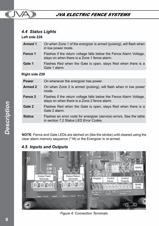
4.5 Inputs and Outputs
Figure 4: Connection Terminals
4.4 Status LightsLeft side Z28
Armed 1 OnwhenZone1oftheenergizerisarmed(pulsing),willflashwhenin low power mode.
Fence 1 Flashes if the return voltage falls below the Fence Alarm Voltage, stays on when there is a Zone 1 fence alarm.
Gate 1 Flashes Red when the Gate is open, stays Red when there is a Gate 1 alarm.
Right side Z28
Power On whenever the energizer has power.Armed 2 OnwhenZone2isarmed(pulsing),willflashwhenin lowpower
mode.Fence 2 Flashes if the return voltage falls below the Fence Alarm Voltage,
stays on when there is a Zone 2 fence alarm.Gate 2 Flashes Red when the Gate is open, stays Red when there is a
Gate 2 alarm.Status Flashes an error code for energizer (service) errors. See the table
in section 7.2 Status LED Error Codes.
Output Feed terminals
Output Return terminals
16VAC
16VAC Only!
Keypad Control Control Inputs Outputs
NOTE: Fence and Gate LEDs are latched on (like the strobe) until cleared using the clear alarm memory sequence (*1#) or the Energizer is re-armed.

9
JVA ELECTRIC FENCE SYSTEMS JVA ELECTRIC FENCE SYSTEMSDescription
4.5.1 Relay FunctionsAll relays can be set to any of the available functions (user assignable).
Relay 1 is (21x#)Relay 2 is (22x#) etc.The modes are explained in the table below.
The defaults for the Z28:Relay 1 Strobe 1Relay 2 Strobe 2Relay 3 Siren.
Value (x) Mode0 Zone 11 Zone 1 or Disarmed2 Armed 13 Zone 24 Zone 2 or Disarmed5 Armed 26 Zone 1 or Zone 27 General8 Siren9 Strobe 1
10 AC Fail11 Low/Bad Battery13 Strobe 214 Gate 1 or 215 Siren caused by Gate 1 or 216 Armed in Low Power Mode17 Group Armed (Note 3)18 Group General
Relay Functions
NOTES:1. Thesedefaultsweredifferentinpre7V64firmware.2. Thesirenandstrobeswitched12Voutputscanbeusedtodriveexternalbuffer
relays.3. Group relay functions are only operable on the group master.

10
JVA ELECTRIC FENCE SYSTEMS JVA ELECTRIC FENCE SYSTEMSDe
scrip
tion
4.6 4-Line LCD Keypad (PTE0240)
Introduction
The JVA 4-Line LCD Keypad is an integral component in the JVA Security Electric Fence product range. Providing a centralised interface between the Customer and their Perimeter Security Solution; it displays the current condition of each security device connected and can draw attention to adverse fence conditions. The keypad is used to control individual fence Energizers, Monitors or the entire site. The Customer has access to all of these features via a Menu Driven system or by entering key sequences. Security Installers also use the keypad to configure the JVA Securitydevicestothecustomer’sneeds.
Features and Benefits
The PTE0240 LCD keypad is a second generation Z-Series Keypad
• Menudriveninterface• 4-lineBacklitLCDdisplay• Quickarm/disarmkeys• 500-entryEvent-Log• Battery-BackedRealTimeClock• Control,monitorandprogramanyZ-Seriesdevice• Displaysarm/disarmedstatusandanytroubleoralarm• ShowsfencevoltagesforZ-Serieselectricfenceenergizersandmonitors• Programmablezonenames• Keyareaglowsredonalarm• EventLogstoresDateandTimeofAlarmorTrouble
Limitations1.TheMenu-drivenprogrammingrequires8v20orhigherfirmwareinEnergizers.2. As the firmware is upgraded from time to time, an older keypadmay not be
compatiblewiththelatestZ-Seriesdevices.Thefirmwareversioncanbeseenbypressing *9#.

11
JVA ELECTRIC FENCE SYSTEMS JVA ELECTRIC FENCE SYSTEMSDescription
Opening the Keypad
Push the 4 side tabs in to release the cover from the base. This can be done one side at a time. Once the cover has been removed from the base plastic, the keypad hardware will slide up to release it from the base.
Installation
The Keypad only requires three wire connections to JVA Energizers or Monitors. This is the +12V, GND and DATA connections on the back of the Keypad circuit board.

12
JVA ELECTRIC FENCE SYSTEMS JVA ELECTRIC FENCE SYSTEMSDe
scrip
tion
When connecting a Group of Energizers together, the +12V wire is only required between the Keypad and Energizer. The other Energizers are connected together using the GND and DAT terminals only.
Keypad terminals on a JVA Single Zone Energizer
Keypad OperationNote: Z-Series Energizers/Monitors have the following Default PINsUser PIN: 1234Installer PIN: 012345
Discovering Energizers
Function Key 1 Key 2 Key 3 Key 4Discover Devices connected to the Keypad * 6 8 #

13
JVA ELECTRIC FENCE SYSTEMS JVA ELECTRIC FENCE SYSTEMSDescription
The Keypad needs to discover all of the Energizers/Monitors connected to the Keypad for it to work properly. This is best achieved after each Energizer/Monitor hasbeenconfiguredandwiredtogetherinagroup.Thedisplaywillshow“Analysing”followed by the device type connected at each zone.
NOTE: All Energizers/Monitors need to be Disarmed before starting the Discovery process.
Arming/Disarming the Site Using the Keypad
To Arm the site, press the Lock button.It will ask for your PIN. Enter the USER PIN and press #
To Disarm the site, press the Un-Lock button.It will ask for your PIN. Enter the USER PIN and press #
To Silence a Siren on an Energizer/Monitor press the Menu Button. It will ask for your PIN. Enter the USER PIN and press #Pressthe#keyontheMenuitem“SilenceSiren”A short-cut for this is to just enter 1470# directly.
Keypad Status Display
In normal operation the keypad shows a Summary Page followed by the status of each device connected to the Keypad.
Summary page:
Z14 page:
JVA Security13:17 01/11/2015DisarmedAll OK
TheInstaller’sDetails(DealerMessage)24hr Clock and DateIf the site is Armed/Part Armed or DisarmedIf the site is in Alarm/Trouble or All OK
ZONE 1Feed:8.6kV Ret:7.5kVAlarm: Fence
The Name of the Zone (Zone Label)The Energizer VoltagesAlarms/Troubles are displayed here
The keypad will automatically scroll the display through all relevant information on each connected Energizer/Monitor. Each screen is shown for about 5 seconds. To pause this, press # and the auto scrolling will stop for 20 seconds.
Pressing the # key again will advance the display one step.

14
JVA ELECTRIC FENCE SYSTEMS JVA ELECTRIC FENCE SYSTEMSDe
scrip
tion
The keypad will automatically display a new Zone Alarm or Trouble and it will remain on this page for 3 minutes. Pressing # again will advance the screen. If the Keypad beeper is sounding, any key press will silence it.
Keypad Menu
The Keypad Menu system can be accessed by pressing the Menu key.Key in either the USER PIN or INSTALLER PIN followed by the Enter key to proceed.To access the Menu items below Exit Menu the Installer PIN is required.
Main Menu
Menu Function (when # key is pressed)Mute Siren Mutes Energizer or Monitor Sirens currently sounding
Clear Alarms Sends the Clear Alarm Memory command to the Energizers/Monitors. Thiswillclear“LatchedFenceAlarms”iftheproblemhasbeencleared.
Show Event Log Displays the Event Log. Use Up/Down keys to scan through events.The # key will exit the Log
Arm Low Power Arm the Site in Low Power Mode
Arm High Power Arm the Site in High Power Mode
Test Menu See Test Menu
Keypad options See Test Menu
Keypad OptionsSet Clock Displays the current clock for editing. See Event Log.
The Event log contains information about Alarms, Troubles and Arm/Disarm commands. Each event is displayed on a separate page. Press the Up or Down key to change pages. Press # to exit the Log. The mostrecententryisdisplayedwhenthelogisfirstopened.Setting the Clock
Menu Function (when Enter key is pressed)
Analyse group Discovers the Energizers connected to the Keypad
Siren Test Turns on the Energizer/Monitor Siren Outputs for 2 seconds
Battery Test Triggers the Battery Test in connected Energizers/Monitors. See the LCD display of the Energizer for the results.
Show Model Displays the Keypad Version
Reset Energizers Forces the Energizers to reset

15
JVA ELECTRIC FENCE SYSTEMS JVA ELECTRIC FENCE SYSTEMSDescription
Menu Function (when # key is pressed)Show Shortcuts Displays commonly used Key Sequences for reference
Remember User PIN / Forget User PIN
Thiswill‘save’theUSERPINentered.Fromnowon,theQuickArm/Disarm buttons will not require a PIN to operate. Pressing Menu button immediately enter the Menu system as well.Deletethe‘saved’USERPIN
Exit Menu Exits the Keypad Menu
Program Device
Program SectorsClear Log Requires Installer PIN to access. Clears the Event Log
Program this Keypad
Requires Installer PIN to access. See Program Device:Requirements for Menu Driven Programming
Forthissystemtoworkeffectively,allconnectedEnergizers/Monitorsneed to be Mk2 protocol compliant. This version is usually found in the Black Plastic box, rather than a Silver Plastic box.
ProcedureThe Keypad takes around 10 seconds to enter Menu Driven Programming mode. Once entered, the list of connected devices will be listed.UsetheUp/Downarrowtochoosethedevicetobeconfigured.Press#andtheKeypadwillLoadtheconfigurationfromtheEnergizer.Use the Up/Down arrows to move around the options and the Left/Right arrows to change the selected value.
Options with >> displayed have a SubMenu that is accessed by pressing the Right Arrow. Use the Up/Down arrows to select the new options and Left/Right to change the selected value.To exit this SubMenu, press the Up arrow till the cursor is at the << line. Now press the Left Arrow.
Press#atanytimetoSavethenewconfigurationtotheDevice.Press*atanytimetoDiscardtheconfiguration.
Exiting Device ProgrammingPress the Menu at any time to completely exit Device Programming.
Program SectorsProgram this Keypad
Default Keypad Returns the keypad to Factory Defaults

16
JVA ELECTRIC FENCE SYSTEMS JVA ELECTRIC FENCE SYSTEMSDe
scrip
tion
Event Log
The Event log contains information about Alarms, Troubles and Arm/Disarm commands. Each event is displayed on a separate page. Press the Up or Down key to change pages. Press # to exit the Log. The most recententryisdisplayedwhenthelogisfirstopened.
Setting the Clock
The clock is formatted to 24 hour time followed by the Day/Month/Year.
Use the number keys to set the new value for the current cursor location. Each number pressed will move the cursor to the right. If the keypad detects anerror,thecursorwillreturntothefirstlocationandtheoriginaldatetimewillbedisplayed again.
The entire Time and Date needs to be entered before the new value is saved. Pressing the Enter Key at any time during the process will cancel the update.
Log Entry: 3714:35 13/02/15Zone 1Fence Alarm
Set Time and Date hh:mm dd/mm/yy14:35 13/02/15--:-- --/--/--
Test Menu
Menu Function (when Enter key is pressed)Analyse Group Discovers the Energizers connected to the KeypadSiren Test Turns on the Energizer/Monitor Siren Outputs for 2 secondsBattery Test Triggers the Battery Test in connected Energizers/Monitors.
See the LCD display of the Energizer for the resultsShow Model Displays the Keypad VersionReset Energizers Forces the Energizers to reset
Keypad Options
Menu Function (when Enter key is pressed)Press Beeps Turns ON/OFF the key press beepsChime Sounds Turns ON/OFF the Gate Chime SoundsError Sounds Turns ON/OFF the Error Sounds when entering a PIN for
Energizer controlAlarm Sounds Turns ON/OFF the Keypad Beeper sounding for a new
Alarm/TroubleBacklight Cycles through the Backlight options (ON / Timeout / OFF)

17
JVA ELECTRIC FENCE SYSTEMS JVA ELECTRIC FENCE SYSTEMSDescription
Program DeviceRequirements for Menu Driven Programming
Forthissystemtoworkeffectively,allconnectedEnergizers/MonitorsneedtobeMk2protocol compliant. This version is usually found in the Black Plastic box, rather than a Silver Plastic box.
Procedure
The Keypad takes around 10 seconds to enter Menu Driven Programming mode. Once entered, the list of connected devices will be listed.
Use the Up/Down arrow to choose the device to beconfigured.Press#andtheKeypadwillLoadtheconfigurationfromtheEnergizer.
Use the Up/Down arrows to move around the options and the Left/Right arrows to change the selected value.
Options with >> displayed have a SubMenu that is accessed by pressing the Right Arrow. Use the Up/Down arrows to select the new options and Left/Right to change the selected value.
To exit this SubMenu, press the Up arrow till the cursor is at the << line. Now press the Left Arrow.
Press#atanytimetoSavethenewconfigurationtotheDevice.
Press*atanytimetoDiscardtheconfiguration.
Exiting Device Programming
Press the Menu at any time to completely exit Device Programming.
Select Device...ID: 1-Z25ID: 2-Not ConnectedID: 3-Z18
High Power 8.5Low Power 1.1.Fence 1 Alarm 4.0Fence 2 Alarm 4.0
UnusedGroup ID 1Input 1 >>. Input 2 >>
<< Input 1 . Trigger N/Open Function Arm All
18
JVA ELECTRIC FENCE SYSTEMS JVA ELECTRIC FENCE SYSTEMSDe
scrip
tion
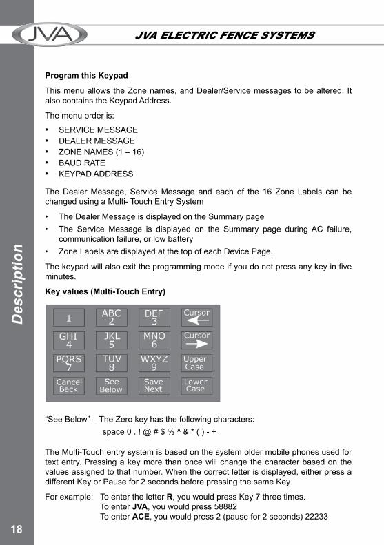
Program this Keypad
This menu allows the Zone names, and Dealer/Service messages to be altered. It also contains the Keypad Address.
The menu order is:
• SERVICE MESSAGE• DEALER MESSAGE• ZONE NAMES (1 – 16)• BAUD RATE• KEYPAD ADDRESS
The Dealer Message, Service Message and each of the 16 Zone Labels can be changed using a Multi- Touch Entry System
• TheDealerMessageisdisplayedontheSummarypage• The Service Message is displayed on the Summary page duringAC failure,
communication failure, or low battery• ZoneLabelsaredisplayedatthetopofeachDevicePage.
Thekeypadwillalsoexittheprogrammingmodeifyoudonotpressanykeyinfiveminutes.
Key values (Multi-Touch Entry)
“SeeBelow”–TheZerokeyhasthefollowingcharacters:space 0 . ! @ # $ % ^ & * ( ) - +
The Multi-Touch entry system is based on the system older mobile phones used for text entry. Pressing a key more than once will change the character based on the values assigned to that number. When the correct letter is displayed, either press a differentKeyorPausefor2secondsbeforepressingthesameKey.
For example: To enter the letter R, you would press Key 7 three times. To enter JVA, you would press 58882 To enter ACE, you would press 2 (pause for 2 seconds) 22233

19
JVA ELECTRIC FENCE SYSTEMS JVA ELECTRIC FENCE SYSTEMSDescription
Changing the Keypad Number options (Arrow Keys)
The Keypad BAUD and Keypad ID options can be changed using the Up/Down Arrow Keys. Press # when the correct value has been selected. Pressing the * key will discard any changes and the display will show the previous option.
Group ConnectionUsing more than one Keypad
Function Key 1 Key 2 Key 3 Key 4 Key 5 Key 6 Key 7 Key 8Re-analyse the keypad group USER PIN * 6 8 #
Up to three keypads may be used to remotely monitor and control Z-Series devices.
To operate correctly, each keypad must be configured to use a unique keypad address. This is achieved by connecting one keypad (at a time) to the master Z-Series device and updating the keypad address.Onceallkeypadshaveadifferentaddress, all can be connected to the system. A recommendation is that one keypad is kept at address 1.
If the security system is to use a PC based interface such as Perimeter Patrol, keypad address 2 should not be used by a keypad. The PC software uses this address to control the Z-Series devices. Once all Keypads are connected, enter the Re-analyse the keypad group command listed above.
NotesThingstorememberwhenconfiguring/usingthekeypad.
• Zone1mustbeconnectedtothegroup.Ifitisnotconnected,theotherZ-Seriesdevices in the group will not send their data to the keypad generating Coms Fail alarms on the keypad.
• Ifthekeypadisunresponsive,thisislikelyduetotheZ-Seriesdevicelookingforother keypads in the group. Be patient. Wait a few seconds and try again.
• AslaveZ-SeriesdevicedisconnectedfromtheGroupwillonlytalktoakeypadifit has a keypad address of 1 or 8.

20
JVA ELECTRIC FENCE SYSTEMS JVA ELECTRIC FENCE SYSTEMSDe
scrip
tion
Sum
mar
y of
Key
pad
Key
Seq
uenc
esD
efau
lt IN
STAL
LER
PIN
01
2345
Def
ault
USE
R P
IN
1234
Ener
gize
r Fun
ctio
nKe
y 1
Key
2Ke
y 3
Key
4Ke
y 5
Key
6Ke
y 7
Key
8Ke
y 9
Key
10Ke
y 11
Key
12Ar
m/D
isar
mU
SER
PIN
#Si
lenc
e th
e En
ergi
zer S
iren
14
70
#St
art P
rogr
amm
ing
the
Z-Se
ries
ener
gize
rIN
STAL
LER
PIN
*0
#St
art P
rogr
amm
ing
the
Keyp
adIN
STAL
LER
PIN
*0
1#
Exit
Prog
ram
min
g (a
ny m
ode)
*#
Cha
nge
a U
ser P
IN, 4
Dig
itsU
SER
PIN
*0
#N
EW U
SER
PIN
#C
hang
e th
e In
stal
ler P
IN, 6
Dig
its N
OTE
10
0N
EW IN
STAL
LER
PIN
#Ar
m A
ll Zo
nes
(Mul
ti-zo
ne g
roup
s)U
SER
PIN
*1
0#
ArmSpecificZone(uptoZone15)
USE
R P
IN*
1Zo
ne N
umbe
r#
Dis
arm
All
Zone
sU
SER
PIN
*2
0#
DisarmSpecificZone(uptoZone15)
USE
R P
IN*
2Zo
ne N
umbe
r#
Switc
h Al
l Zon
es to
low
pow
er m
ode
USE
R P
IN*
41
#Sw
itchSp
ecificZo
netolowpow
ermode
USE
R P
IN*
41
Zone
Num
ber
#Sw
itch
All Z
ones
to h
igh
pow
er m
ode
USE
R P
IN*
42
#Sw
itchSp
ecificZo
netohighpowermode
USE
R P
IN*
42
Zone
Num
ber
#Ar
m G
ate
circ
uits
onl
yU
SER
PIN
*4
#By
pass
Sire
n (A
ll Zo
nes)
USE
R P
IN*
52
#BypassSpecificZoneSiren
USE
R P
IN*
52
Zone
Num
ber
#R
e-en
able
Sire
n (A
ll Zo
nes)
USE
R P
IN*
51
#Re-enableSpecificZoneSiren
USE
R P
IN*
51
Zone
Num
ber
#By
pass
Gat
e Al
arm
(All
Zone
s)U
SER
PIN
*5
4#
BypassSpecificGateAlarm
USE
R P
IN*
54
Zone
Num
ber
#R
e-en
able
Gat
e Al
arm
(All
Zone
s)U
SER
PIN
*5
3#
Re-enableSpecificGateAlarm
USE
R P
IN*
53
Zone
Num
ber
#
1.
To ch
ange
the
Inst
alle
r PIN
, the
Ene
rgiz
er n
eeds
to b
e in
Ene
rgiz
er P
rogr
amm
ing
Modefirst.(“StartProgrammingtheZ-Se
riesenergizer”function)

21
JVA ELECTRIC FENCE SYSTEMS JVA ELECTRIC FENCE SYSTEMSDescription
Ener
gize
r Fun
ctio
nKe
y 1
Key
2Ke
y 3
Key
4Ke
y 5
Key
6Ke
y 7
Key
8Ke
y 9
Key
10Ke
y 11
Key
12
Arm
in A
gric
ultu
ral M
ode
(No
Alar
ms)
USE
R P
IN*
9Zo
ne N
umbe
r#
ResetandDisplayfirmwareversionnumber
USE
R P
IN*
68
#
Res
et a
nd re
turn
to fa
ctor
y de
faul
tsIN
STAL
LER
PIN
*6
8#
Ener
gize
r Fun
ctio
nKe
y 1
Key
2Ke
y 3
Key
4
Cle
ar A
larm
mem
ory
*1
#
Dis
play
the
Gro
up ID
of t
he E
nerg
izer
*2
6#
Sire
n te
st*
63
#
Batte
ry t
est
*6
4#
Dis
play
the
Stor
ed J
oule
s*
67
#
Re-
anal
yse
the
grou
p*
68
#Pa
nic
– Th
e En
ergi
zer/M
onito
r will
reac
tde
pend
ing
on it
s Pa
nic
setti
ngs
KeypadSpecificFunction
Key
1Ke
y 2
Key
3Ke
y 4
Cha
nge
the
Keyp
ad M
essa
ges
to E
nglis
h*
31
#
Cha
nge
the
Keyp
ad M
essa
ges
to S
pani
sh*
32
#
KeypadAudibleFeedbackOn/Off
*5
1#
KeypadChimesOn/Off
*5
3#
KeypadErro
rTonesOn/Off
*5
4#
LocalKeypadAlarmsOn/Off
*5
5#
BacklightmodeOn/Timeout/Off
*8
#
Dis
play
Key
pad
Mod
el*
9##

22
JVA ELECTRIC FENCE SYSTEMS JVA ELECTRIC FENCE SYSTEMSDe
scrip
tion
4.7 Internal Beeper/Keypad BeeperDepending on the chime mode setting, the internal beeper and keypad beeper will sound when there is a fence alarm, a gate alarm or a general alarm or a door chime. Onflatbatterythekeypadwillalwaysbeep4timesbeforetheenergizerautomaticallyenters low voltage mode to preserve the battery. On AC Fail it will beep.
4.8 CablingHigh voltage cabling (fence lead out and returns) should be run using suitably rated cable. Double insulated electric fence underground cable is suitable. High Voltage Cables must never be run within the same conduit as Low Voltage Cables. A minimum distance of 30mm should be kept between High Voltage and Low Voltage cables.
4.9 Lightning ProtectionAlthough the Z28 contains internal lightning protection elements, external lightning protection elements such as additional external lightning kits available from your local dealer, are recommended as they would help to reduce lightning damage even further.
4.10 Earth Loop MonitoringThe Z28 has two fence earth terminals which when wired into a series looped fence systemenable theenergizer tomonitor theearthcircuit. In thisconfiguration,onlyone earth spike location must be used. If this is not required the installer can loop the two earth terminals at the energizer and then connect the earth spikes to one of the parallel earth terminals.
4.11 Noise and InterferenceThe Z28 contains a microprocessor. Extreme electrical noise can upset microprocessors. The most likely cause of such noise is the high voltage output from the unit itself. In the event of erratic behaviour, check that the high voltage wiring is firmlyconnectedtotheterminalsandthatnosparkingisseen.TheZ28isdesignedtoself-recover from interference,poweringoff(bothACandbattery)shouldnotbenecessary.
4.12 Programmable OptionsThe Z28 has many programmable options. These are also known as setup parameters. To alter these options a keypad must be used. The options are explained in the 4 line keypad section on page 20. Each parameter has a factory set default.
4.13 Low Power Mode Z28 energizers can be switched into low power mode. Low Power mode may be used in situations where the fence is not required to be a deterrent but is still required to actively detect intrusion. In Low Power mode the fence live wires operate at a much lower voltage, typically 900V peak. See Programming Options on page 20 for details on using the keypad to set low voltage mode.

23
JVA ELECTRIC FENCE SYSTEMS JVA ELECTRIC FENCE SYSTEMSDescription
4.14 Control Inputs4.14.1 Control Inputs
The Z28 has 3 control inputs. These default to:
Input 1 – Arm/DisarmInput 2 – Gate 1Input 3 – Gate 2 or low voltage mode input.
The gate inputs may be wired to a gate switch to trigger an alarm when a gate is opened.
If the unit is disarmed, the gate input may be set to chime mode. See Programming Device on page 17.
NOTE: If not used, the Gate 1 and Gate 2 inputs must be bridged to the Com terminal.
Inputs2and3canbeconfiguredforotherfunctions.SeeProgramming Device on page 17.
4.14.2 Control Input Functions
On/Off (Arm/Disarm)WhenconfiguredasanOn/OffInput,theControlInputArmsorDisarmstheFenceZone.On/ArmwillmaketheFenceLive(HighVoltageontheFence),whileOff/Disarmwill make the fence Safe (No fence voltage)
Gate InputWhenconfiguredasaGateInput,theControlInputmaybewiredtoagateswitchtotrigger an alarm when the gate is opened for longer than the Gate Entry/Exit Delay time (Option 13). The timer will reset to zero when the gate closes. If the energizer is disarmed, the Gate Input may be set to Chime Mode. See section 9, option 14.
High/Low Power ControlWhenconfiguredtocontrolHigh/LowPowermode,theControlInputisabletochangethe Energizer Output (While Armed) to either High Power or Low Power modes. It is also used to determine what Power Mode to start in when the energizer is Armed using a Control Input.
4.14.3 Keyswitch Inputs
By default one keyswitch is used to arm and disarm both zones. The Z28 can be configuredfortwokeyswitchestoarmanddisarmindividualzones.
4.15 Group Simultaneous Pulse FeatureAll JVA Z Range models may be linked to form a group to power multiple zones. See Group Mode, page 31.

24
JVA ELECTRIC FENCE SYSTEMS JVA ELECTRIC FENCE SYSTEMSIn
stal
latio
n
5. INSTALLATION
JVA recommends installation by qualified technicians.
5.1 Installation Steps1. Readtheentiremanualfirst!2. Design and build the fence. (Beyond the scope of this manual.)3. Decide where the JVA Z28 is to be mounted. If on an external wall it should
behousedwithin awaterproof equipment box anddefinitely not in directsunlight.
4. Mount the unit by hanging the housing on the two nail-in anchors provided. If necessary, two extra mounting holes can be used at the bottom of the housing.
5. Ifusingakeypad,removetherearhousingofthekeypadandfixit tothewall.
6. Wire the low voltage cables to the PCB terminals (right side)*. (See page 8)7. Wire the high voltage cable to the PCB terminals*. (See page 8) If earth
monitoring is not going to be used on the fence, connect a bridge wire from earth out to earth return.
8. Fit the battery leads to the battery. The Status LED should blink twice to show mains fail.
9. Mount the 220 – 16V transformer and connect the 16V side to the Z28 16V input terminals. (AC is not polarity sensitive.) Do not connect a live or neutral to the earth terminal.
10. Theunit isdesignednottostartwhenfirstpoweredupirrespectiveofthestate of the inputs.
11. Replace the front cover.12. Turn AC power on.13. Arm and disarm the energizer via the keyswitch or keypad, if fitted. The
Status LED should stop blinking.14. If using a keypad, type *68#. The keypad will analyse the zones.15. Arm the unit. The LCD display will now show the fence voltage.16. Check to ensure that a short anywhere on the fence triggers the alarm.17. On handing the system over to the owner/user, explain how to change the
user PIN. Leave a User Manual with the user.
*NB Keep high voltage and low voltage cables at least 100mm apart. Do not run high and low voltage cables in the same conduit.

25
JVA ELECTRIC FENCE SYSTEMS JVA ELECTRIC FENCE SYSTEMSInstallation
5.2 Example Fence Wiring Diagrams
JVA Z28 Energizer Fence Wiring, Including Earth Monitoring
Return 2
Feed Return
Feed 1Earth
Return 1
Fence 1
Earth
Feed 2
Fence 2
Earth spikes

JVA ELECTRIC FENCE SYSTEMS JVA ELECTRIC FENCE SYSTEMS
26
JVA ELECTRIC FENCE SYSTEMS JVA ELECTRIC FENCE SYSTEMSIn
stal
latio
n
Return 2
Feed Return
Feed 1Earth
Return 1
Fence 1
Earth
Feed 2
Fence 2
Earth spikes
JVA Z28 Energizer Fence Wiring, without Earth Monitoring

27
JVA ELECTRIC FENCE SYSTEMS JVA ELECTRIC FENCE SYSTEMSO
perationJVA ELECTRIC FENCE SYSTEMS JVA ELECTRIC FENCE SYSTEMS
6. OPERATION
6.1 Arm/Disarm ControlThe unit can be controlled by the keyswitch, control input 1 or via a keypad. The keypad also allows instant audiovisual indication of the state of the energizer and therefore the fence it is powering.
If there are two ways to control the energizer both connected at once, i.e. keypad and control inputs, then the last change will determine the result. So if the unit is armed via the keypad and then disarmed at the control input it will disarm.
6.2 Arming the Fence Using the Keypad● Enter your USER PIN number (four digits long; default is 1 2 3 4) and push the #
key.● Make sure the red ARM light comes on.● Thekeypadwillbeeptwicetoconfirmthatthesystemisarmed.● The fence will power up and if all is well (no faults) the system will be ready to
deter and detect. ● If there is a fault on the fence and it cannot achieve full voltage, zone 1 or zone 2 LEDswillflash.
● To disarm the system, enter your USER PIN and press #. This will also clear any fault lights and zone lights which may have been on.
6.3 Turning to Low Power modeTo switch to Low Power mode, enter your USER PIN and press *41#. In Low Power mode the fence will still be powered and any breach will be detected, but the voltage willbemuch lower thannormaloperation.TheARM lightwill flash inLowPowermode.
Enter your USER PIN and press *42# to switch back to Full Power mode.
Alternatively, the unit can be switched to Low Power mode using control input 2, if it has been programmed accordingly.
6.4 When an Alarm OccursIf the system is armed and the fence is tampered with, the corresponding Zone Light willflashontheenergizerandthenremainon.Relaysassignedtoalarmswillturnon. If the energizer is connected to a building alarm system for monitoring, an alarm signal may be sent to the alarm company monitoring the alarm system.

JVA ELECTRIC FENCE SYSTEMS JVA ELECTRIC FENCE SYSTEMS
28
JVA ELECTRIC FENCE SYSTEMS JVA ELECTRIC FENCE SYSTEMSO
pera
tion
Analarmwillalsosoundifinput2isassignedtothe“gateinput”functionandthegate input is opened and the entry/exit delay time has elapsed.
After thesirenhascycledonandoffaccording to the timesandnumbersset inoptions,thesirenwillstopsounding.Theonandofftimingisabletobesetintheoptions. The Strobe will remain on. After a further delay (Auto Rearm Time) the sirenwillagainrespondtothenextalarmconditionwithanewsetofon/offcycles.
If the alarm condition (low fence voltage or gate input) is removed, the siren will stop aftertheendofthecurrent“on”time(SirenOnTime).
If the siren is muted by (entering PIN#)thenthesirenwillenterthenext“off”cycle(SirenOffTime).Ifthealarmconditionisstillpresent(voltageislow)thesirenwillsoundagain after the preset “off” time. If the alarm condition is not present theenergizer is instantly rearmed, irrespective of the auto-rearm setting.
6.5 To Silence the Alarm● Enter your USER PIN and press #. This will silence the alarm but not disarm the
system; the Armed Light will still be on. If Auto-Rearm is set, the system will be readyforthenextalarm.Notethatthefollowingfunctionshaveaneffectonalarmtiming:SirenOntime,SirenOfftime,SirenCycles,AutoRe-armtime.
● Thezonelightsonthekeypadwillflashtoshowwherethebreachoccurred.● The siren and strobe are ready to respond again if triggered.● To disarm the system, enter your USER PIN and press # again. The zone light
will remain lit until the Clear Alarm Memory command (*1#) is entered.● Alternatively, disarming using the key switch will reset the alarm.
6.6 Changing the USER PIN Number● Enter the old 4-digit USER PIN and press *0#. This enters User Programming
mode.● Enter your new USER PIN (must be 4 digits) and then #.● Press *# to exit User Programming mode.● Make sure your new USER PIN works by using it to arm the energizer.● The default PIN is 1 2 3 4.
6.7 Standby BatteryShould there be a loss of mains power, the Power Lightonthekeypadwillgooff.If the loss of power is prolonged, the battery may discharge power and become ineffective.ThePower Lightwillstarttoflashindicatingabatterylowpowerproblem.If the standby battery requires replacement, the Status Lightwillflashthreetimes.
6.8 Status LightIf the energizer develops an internal fault, the Status Lightwillflashacode.Seesection 7.2 (page 30).

29
JVA ELECTRIC FENCE SYSTEMS JVA ELECTRIC FENCE SYSTEMSTechnical Inform
ationJVA ELECTRIC FENCE SYSTEMS JVA ELECTRIC FENCE SYSTEMS
7. TECHNICAL INFORMATION
Label Type DescriptionKeypad 3 Way Supplies power and data line for an external keypad. The +12
source on these terminals is protected with a 1A self-resetting fuse.
Inputs 4 Way Energizer control inputs (dry contact). Defaults to normally open.Can be used for a remote switch or a radio receiver. The receiver may be powered from the keypad +12V terminal. See section 4.
Outputs 4 Way Siren and Strobe or other programmable outputs. See section 4 and 8 (Programming Options).
AC IN 3 Way 16Vac power input. Fused via F3 3A self-resetting fuse.Batt Leads 12V dc or battery connection via F1 (3 Amp self-resetting fuse.
Low Voltage Terminals
Figure 6: Low Voltage Terminals
NOTE: To reset the fuse, remove power for a few seconds and then reapply power.
7.1 Power OptionsThe unit has 2 sources of power, 16VAC and 12VDC (Battery).NOTE: Use only rechargeable batteries. Always ensure adequate ventilation is available for the housing if it contains a battery. Lead acid batteries may emit explosive gases while charging! Always make sure that a battery is connected to the energizer before applying 16 VAC.

JVA ELECTRIC FENCE SYSTEMS JVA ELECTRIC FENCE SYSTEMS
30
JVA ELECTRIC FENCE SYSTEMS JVA ELECTRIC FENCE SYSTEMSTe
chni
cal I
nfor
mat
ion
Status LED Number of Flashes
Interpretation Corrective Action
1 Not used2 16 VAC Mains fail Restore mains power. Can be
bypassedbyfittingJ33 Low battery, bad battery Charge or replace battery4 PCB service fault Return to repair/service centre
Status CodesIf an error occurs, the relay assigned to general alarm will go into alarm state. Minor errors will self clear if the error condition is removed. If the mains power fails, it will not disarm the energizer, nor will low battery. However, without mains power, the battery will eventually be depleted and the energizer will attempt to maintain operation by entering low power mode after 4 warning beeps. If the battery charge continues to fall, the energizer will eventually stop. Once mains power has been restored and the battery has recovered, the energizer will re-arm itself automatically after 4 warning beeps. A PCB fault will disarm the energizer. If an error disarms the energizer, the general and fence alarms will activate.
If an error has momentarily caused the energizer to stop pulsing, this can be corrected by disarming and rearming the unit. Should the error recur, return the unit for service.
7.3 JumpersThe unit has two special purpose jumpers (links). These are listed in the table below.
Jumper Function PurposeJ3 DC only jumper Fit J3 to inhibit mains fail errors, if the intention is
to operate the unit on DC only (as in Solar Power systems)
J4 Factory default jumperOfftoreturnprogram-mable options to factory defaults upon power up
If the energizer needs to be defaulted to factory settings, remove all power – AC and battery and remove the J4 jumper. Reapply the battery power first,then16VACpower.ReapplytheJ4jumperand the unit will be reset to default settings.
Jumpers
7.2 Status Codes
7.4 Multiple KeypadsAll Z series energizers have support for up to three keypads provided the Energizers firmwareversionis7v66andabove.Ifmorethanonekeypadisdesiredoneofthekeypads must have an ID of 2, the other keypads can have an ID number from 1 to 8 but excluding ID 2. If only one keypad is desired any ID number from 1 to 8 can be used.

31
JVA ELECTRIC FENCE SYSTEMS JVA ELECTRIC FENCE SYSTEMSG
roup Mode
JVA ELECTRIC FENCE SYSTEMS JVA ELECTRIC FENCE SYSTEMS
A group must have only 1 master. The other Energizers in the group are slaves. Since the keypad bus is common among the group, one keypad can be used to program all Energizers for all Options except Group Mode (for obvious reasons).
If there is no Master, each Slave will electrify the fence (pulses) when Armed. However, the simultaneous pulse feature will NOT be operating.
Connect the keypad to each Energizer in turn, before linking all Energizers into a group. Set this option, one unit as master the other as slaves.
NOTE 1: Do not interconnect the energizers via the keypad bus until after they are programmed.
NOTE 2: If more than one keypad is used, they will needdifferentaddresses.
NOTE 3: If Perimeter Patrol is used, any keypad in the system should not have address 2, (see page 18 Program this Keypad).
For all Energizers that will be part of a group, the procedure is as follows:
Value Mode0 No Group1 Master2 Slave 13 Slave 24 Slave 35 Slave 46 Slave 57 Slave 6
etc. etc.15 Slave 14
Group Mode (26x#)
1. MakesurethekeyswitchisturnedoffandInput1 is not connected to the Com terminal.
2. Connect the battery.3. Connect the keypad.4. Onthekeypad,enter[Installer’scode][*][0][#],then[26].5. Entertherequiredvalue(e.g.[1]formaster)then[#].6. Enter[*][#]toexitprogramming.7. Connect the group using the keypad bus as per Figure 7.
NOTE: At this time groups are limited to a master and 14 slaves (15 zones total).If more zones are required, PAE 212 LAN boards can be used.In Group Mode, only one keypad can be used. NOTE: In some markets Group Mode may not be available.For details on group wiring and operation Figure 7.
8. GROUP MODE (26x#)

32
JVA ELECTRIC FENCE SYSTEMS JVA ELECTRIC FENCE SYSTEMSG
roup
Mod
e
Group linking via the Keypad “bus”
The keypad terminals on all Energizers in the group are linked, see Figure 17. Since only one Energizer needs to power the keypad, 3 wires are linked from one Energizer (preferably the Master) to the keypad (optional) and 2 wires to every other Energizer in the group. Do not connect the + lines between Energizers as this could result in some strange behaviour and possibly damage. Note the connections can be a star or daisy chain or any mixture. It is possible for a PC to be added to the group using a keypad to RS232 adaptor (PAE051).
We recommend following these steps in the right order:
1. Disarm all energizers in the group. If energizers are not disarmed Step 10 may not work correctly.
2. Program the keypad address using one of the energizers.
3. Program each energizer with its required address (Master address = 1, Slave 1 address = 2...). Refer to note 4 below.
4. Connect any control/monitoring unit 12V, GND and Data to the Group Master.
5. Connect all the slaves Data and GND to the Group Master.
6. Connect the battery and AC power of the Group Master but do not arm.
7. Connect the battery and AC power of each slave Note: Do not arm them until all the Energizers in the group are connected
8. Wait 5 minutes for all the Energizers to synchronise with the Master
9. Iftherearemorethanonekeypadorcontrolunit,makesuretheyhaveadifferentIDthenresetthegroupusingkeypadcode:[userpin][*] [6][8][#]orPerimeterPatrol“ResetAll”thiswillallowbothkeypadstoberecognisedbyallenergizersinthe group.
10. IfusingaPTE0210keypad(refertoAppendixI),enterthekeysequence[*][6][8][#]toautomaticallyre-scanthegroupandcheckwhatenergizersareconnected.
11. Armthegroupusingkeypad[1][2][3][4][*][1][0][#]orPerimeterPatrol,makesure all Energizers are activated.
NOTES:
1. Members of a group can be individually switched on and off; even themastercanbeturnedoffviainputorkeyswitch(notethattheZ14Rdoesnothaveakeyswitch).
2. A slave will generate a General alarm if the keypad bus is broken between it and the group master.
3. After programming the Keypad may be disconnected, it is not required for group operation.

33
JVA ELECTRIC FENCE SYSTEMS JVA ELECTRIC FENCE SYSTEMSG
roup Mode
4. Asofenergizerfirmware7v83andkeypadfirmware1v09,Z28’sshouldhavean‘empty’IDbetweeneachEnergizer.ThismeansiftheZ28masterID=1,thentheIDofthefirstslaveshouldbe3,not2.
5. When connected to Perimeter Patrol, the arm/disarm function of a keypad is disabled. Control of these functions is through the Perimeter Patrol interface.
6. A Keypad that is connected to a Slave Energizer (that is disconnected from the Group) must have a KEYPAD ADDRESS set to 1 or 8. Otherwise the Energizer will not respond to commands.
PAE 212
LAN
cab
le
Z Series Energizer Z Series Energizer
Z Series Energizer Z Series Energizer
Figure 7: Group Mode LinkingGroup Installation notes
1. If anEnergizer hasn’t beenprogrammedasaMaster or aSlave, it is set as“Standalone”bydefault.
2. All energizers need an appropriate high voltage circuit earth connection.3. Allow for the heat load of multiple Energizers mounted inside a cabinet, approx.
10W each.4. Use shielded or twisted pair cable for the group keypad wiring.

JVA ELECTRIC FENCE SYSTEMS JVA ELECTRIC FENCE SYSTEMS
34
JVA ELECTRIC FENCE SYSTEMS JVA ELECTRIC FENCE SYSTEMSSe
ctor
Set
up T
ests
and
Adj
ustm
ent
9. SECTOR SETUP TESTS AND ADJUSTMENT
With a single sector system there are three considerations for the electric fence monitor voltage level:1. The monitor should trigger the alarm if one of the live wires is shorted to ground.2. The monitor should trigger the alarm if one of the live wires is cut.
Usecommonsenseandturntheenergizeroffwhenmakingchangestothefence,thenturntheenergizerbackontochecktheeffects.
9.1 Basic Fence Tests1. Energise the newly-completed fence.2. UseanElectricFencePowerProbetofindanyconstructionfaults.3. Check that there is voltage on all live wires (continuity) and that there are no shorts
from live to earth. 4. Check the electric fence earth. (See electric fence manuals.) One method is
to make an intentional short from live wire to earthed metal. The voltage at the earthed point should be less than a few hundred volts; the voltage on the earth stake with respect to any nearby earthed metal should be less than a few hundred volts.
5. Record the start and end of fence live wire voltages.6. Record the live wire currents going out from the energizer to the fence.
At this point there must be a reasonable voltage on all parts of the fence. To be an effectivebarrier,thePowerProbe(orvoltmeter)readingsbetweenwires(livetoearth)must be greater than 5.0kV. If they are not, a larger energizer may be required.
9.2 Fault Condition Tests1. To simulate a break, disconnect a joint in the live wires at some convenient point on
the fence, making sure that the wires do not short to ground or between +ve and -ve wires.
2. Check that the energizer fence alarm activates. If not, check the voltage (using an electric fence voltmeter) at the inputs to the monitor. Set the fence alarm voltage level higher than this voltage. If there is still considerable voltage, you may have induced voltage in the live return wires. If so, reduce the induced voltage by placing a 3000 Ohm, 10 Watt resistor between the live return and earth return terminals at the monitor.
3. Reconnect the live wires.4. Place a short on the fence live wires.5. Check that the monitor goes into alarm.6. Remove the short.7. Do Steps 4 – 6 for both zones.

35
JVA ELECTRIC FENCE SYSTEMS JVA ELECTRIC FENCE SYSTEMSStandard Requirem
entsJVA ELECTRIC FENCE SYSTEMS JVA ELECTRIC FENCE SYSTEMS
10. SOME STANDARD REqUIREMENTS FOR ELECTRIC SECURITY FENCES
The JVA range of energizers has been extensively tested and certified in accordance with international standards. JVA does not take responsibility for the erection standards of the fence. It is the responsibility of the erector to consult and comply with the Standards and Codes of Practice for the installation and erection of electric security fences. For the user’s convenience, we include some Standard Requirements here but the installer also needs to consult standards such as SABS 1063, 0142, SABS IEC 60335-2-76.
10.1 DefinitionsPhysical BarrierA barrier of not less than 1.5m in height and intended to prevent inadvertent contact of persons with the conductors of the electric fence.
NOTE: Physical barriers are typically constructed from vertical sheeting, rigid vertical bars, rigid mesh or rods of chain wire mesh.
Public Access AreaAny area where persons are protected from inadvertent contact with pulsed conductors by a physical barrier (see above).
Pulsed ConductorsConductors that are subjected to high voltage pulses by the energizer.
Secure AreaAn area where a person is not separated by a physical barrier (see above) from pulsed conductors (see above) below 1.5m.
10.2 Installation, Operation and Maintenance10.2.1 Electric security fences and their ancillary equipment shall be installed,
operated and maintained in a way that minimises danger to persons, and reduces the risk of persons receiving an electric shock unless they attempt to penetrate the physical barrier, or are unauthorised to be in the secure area.
10.2.2 A space of 2.5m shall be maintained between uninsulated electric fence conductorsoruninsulatedconnectingleadsthataresuppliedfromdifferentenergizers. This space can be less where the conductors or the connecting leads are covered by insulating sleeving, or consist of insulated cables that are rated to at least 10kV.

36
JVA ELECTRIC FENCE SYSTEMS JVA ELECTRIC FENCE SYSTEMSSt
anda
rd R
equi
rem
ents
10.2.3 The requirement in 10.2.2 does not apply in cases where the separately energised conductors are separated by a physical barrier that has no openings greater than 50mm.
10.2.4 A vertical separation of not less than 2m shall be maintained between pulsed conductorsfedfromdifferentenergizers.
10.2.5 Mains supply wiring shall not be installed in the same conduit as signalling leads associated with the electric security fence installation, but shall be installed in accordance with the requirements given in SABS 0142.
* NB. (Fence HT leads must under no circumstances be routed in the same conduit as any other wiring.)
10.3 Warning SignsNOTE: Regulation warning signs are available from all JVA ElectricFencecentresandallJVAcertifieddealers.
10.3.1 Electric security fences shall be identified byprominently placed warning signs that shall be legible from the secure area and from the public area.
10.3.2 Each side of the electric security fence will have at least one warning sign.
10.3.3 A warning sign shall be placed:a. at each gateb. at each access point c. at intervals not exceeding 10md. adjacent to each sign with regard to chemical hazards, for emergency
services information.
10.4 GatesGates in electric security fences shall be capable of being opened without the person who is operating the gate receiving a shock.
10.5 Earthing10.5.1 Where an electric security fence passes below bare power line conductors,
thehighestmetallicelementshallbeeffectivelyearthedforadistanceofnotless than 5m on either side of the crossing point.
10.5.2 The distance between any electric fence earth electrode and other earth systems shall be not less than 10m, except when the earth system is associated with a graded earth mat. The earth electrode shall comply with SASS 10611. Amendment 1, Deco 2000 1.
10.5.3All exposed conductive parts of the physical barrier shall be effectivelyearthed.

37
JVA ELECTRIC FENCE SYSTEMS JVA ELECTRIC FENCE SYSTEMSStandard Requirem
ents
10.6 Protection10.6.1 All ancillary equipment connected to the fence circuit shall be designed to
provide a degree of isolation between a fence circuit and the supply mains equivalenttothatspecifiedfortheenergizer.
10.6.2 Protection from weather shall be provided for the ancillary equipment unlesstheequipmentiscertifiedbythe manufacturer as being suitable for use outdoors, and is of a type with a minimum degree of protection IPX4 (protected against splashing water).
Figure 1Typical constructions where the electric security fence is exposed to the public.
Power line voltage
Minimum clearance
<1 000 3m>1 000 and <33 000 4m
>33 000 5mFence to Powerline Minimum
Clearance

JVA ELECTRIC FENCE SYSTEMS JVA ELECTRIC FENCE SYSTEMS
38
JVA ELECTRIC FENCE SYSTEMS JVA ELECTRIC FENCE SYSTEMSSt
anda
rd R
equi
rem
ents
Figure 2Typical fence constructions where the electric security fence is installed in windows and skylights.
Figure 3Prohibited zone for pulsed conductors.
Key: Electric security fence Physical barrier
Key: Electric security fencePhysical barrierProhibited zone

39
JVA ELECTRIC FENCE SYSTEMS JVA ELECTRIC FENCE SYSTEMSW
arrantyJVA ELECTRIC FENCE SYSTEMS JVA ELECTRIC FENCE SYSTEMS
All JVA products carry a 2-year warranty against defective components and workmanship. The warranty excludes damage caused by acts of Nature such as lightning or flooding, power supply surges, rough handling, malicious actions orincorrect wiring.
Whilst every effort has been made to check that the information contained isaccurate, JVA Technologies Pty Ltd will not be liable to loss or damage resulting from construction, operation or failure of any installation or system. Installation of security electric fences should be made by trained professionals with regard to the relevant local standards and workplace health and safety requirements.
Product model purchased: .................................. Serial No: ...........................
Customer Name: ..................................................................................................
Address: ..................................................................................................
..................................................................................................
..................................................................................................
Postal Code: .......................................
Tel. No: Cell: ................................ Landline: ....................................
email: ..................................................................................................
Date purchased: ........................................
Invoice No: ........................................
Dealer Name: ..................................................................................................
Dealer’s Stamp
11. WARRANTY
Mail to: SA JVA Service Department P.O. Box 13898, Cascades 3202

40
JVA ELECTRIC FENCE SYSTEMS JVA ELECTRIC FENCE SYSTEMS
CUSTOMISED CODES
Customer Pin No. ....................
Installer Pin No: .......................
INSTALLER DETAILS
Name .........................................................
Phone No. .................................................
Date Of Installation ..................................
12. COMPLIANCE CERTIFICATE

JVA ELECTRIC FENCE SYSTEMS
GSM MONITORS AND CONTROLS JVA ENERGIZERS
USING A CELL PHONEZ14 STANDARDAND BI-POLAR ENERGIZERS
Z-RANGE
WEB SERVER MONITORS AND CONTROLS
ENERGIZERS VIA THE INTERNET
Z14
Z18 STANDARDAND BI-POLAR ENERGIZERS
Customer SupportFor assistance: If you have any questions or need further assistance, please call your nearest JVA dealer. SA Tel. No.: 0861 782 349.For service or repairs: If a service or repair is required, please package and label your energizer carefully and return it to your local JVA Service Centre.For warranty repairs: Include proof of purchase, e.g. invoice.Note: Repair centre details are displayed on the back cover of this manual.
Z18
Z28
Z28 STANDARDENERGIZER
RANGE FEATURES INCLUDE
9.2 9.0
LCD voltage display Powerful 4 joules per zone peak output energy Designed to pass IEC60335.2.76 and EMC
standards (reports available on request) Wall mountable, robust enclosure with
detachable PCB chassis for ease of installation and repair
Earth monitor input Gate input Key-switch Keypad programmable Lower-power mode Entry/Exit delay from gate input trigger Switched +12V outputs for Siren and
Strobe (up to 30 Watts for 3 minutes) Microprocessor controlled Outputs may be wired for BiPolar fences
(excluding Z28) Multiple single-zone energizers can be
wired as a group
PERIMETER PATROLCOMPLETE CONTROLSySTEM MONITORING
EVENT LOGGING

JVA ELECTRIC FENCE SYSTEMS
Nearest RSA branch: 0861 782349 • Website: www.jvasecurity.com • e-mail: [email protected]
Bloemfontein36 Kolbe Lane, OranjesigTel: 051 448 6695Cape TownUnit 15, Viking Business ParkPark Road (off Viking Way)Epping IndustriaTel: 021 534 5056Centurion74 Cantonments Road, LyttletonTel: 012 880 0222Durban NorthUnit B, 13 Kenneth Kaunda Road (Old Northway)Tel: 031 563 0274East LondonShop 8 & 9, Paphos ParkDevereaux AvenueTel: 043 726 6652/60East Rand (Jet Park)Aerostar Business Park 219 Jet Park Road, Jet ParkTel: 011 397 3507GeorgeShop 3, 57 York Road, GeorgeTel: 044 874 0669/ 044 873 2958Kimberley29 Schmidtsdrift RoadRhodesdeneTel: 053 861 5631
Klerksdorp72 Central Avenue, FlamwoodTel: 018 468 8273NelspruitUnit 4, 20 Rapid StreetRiverside Industrial ParkTel: 013 752 7152/55North Rand (Kya Sand)174 Bernie Street, RandburgTel: 011 708 6442PaarlShop 2, Huguenot Park, Cnr Klein Drakenstein Road and Van Der Merwe St., PaarlTel 021 862 0886Pietermaritzburg51 Winston Road Tel: 033 342 6722/27PinetownUnit 1, 7 Suffert StreetTel: 031 702 6351Polokwane9 Suez Street, NirvanaTel: 015 292 6273Port Elizabeth45 Mangold Street, Newton ParkTel: 041 365 7178/9Potchefstroom35 Dr James Moroko StreetTel: 018 297 1488
Pretoria1185 Steve Biko Road, (977 Voortrekker Road), Wonderboom SouthTel: 012 335 4290RustenburgShop 7, Waterfall Mall 1 Howick Avenue Tel: 014 537 2884Somerset West4 Broadway CentreUrtel Crescent Tel: 021 851 1978UpingtonUnit 2B, Industria Business Park4 Progressus Street Tel: 054 332 1458Vanderbijlpark5 Prime Business ParkRabie Street Tel: 016 931 0408 VryheidUnit F, 153 President StreetCnr. Hlobane Street Tel: 034 981 0318West Rand (Roodepoort)599 Ontdekkers RoadDelaréyRoodepoortTel: 011 472 8823
JVA RSA SERVICE CENTRES
JVA products are designed by JVA Technologies, Queensland, Australia and distributed to:
AUSTRALIAAFRICA
NEW ZEALAND PHILIPPINESPAKISTAN
LATINO AMERICA
CARIBBEAN
SOUTH EAST ASIA
EUROPE
RUSSIA
INDIA
USA
MEXICO
CENTRAL ASIA
CENTRAL AMERICA
SRI LANKAUNITED KINGDOM


![Product Data Sheet - seoulsemicon.com Y22P_Rev1.0_171… · Luminous Efficacy [lm/W] @700mA Part Number 700mA 1000mA 1500mA 70 6500 299 310 422 586 159 S1W0-2222657003-00000000 …](https://img.dokumen.tips/doc/110x75/5b156f947f8b9a1a398c605c/product-data-sheet-y22prev10171-luminous-efficacy-lmw-700ma-part-number.jpg)