Embed Size (px)
Citation preview

5200710 Rev . GChargemas te r P inner
Chargemaster Pinner,Pinner-R and Pinner-T Arc Resistant Charging Bars
INSTALLATION AND OPERATING INSTRUCTIONS

5200710 Rev . GChargemas te r P inner
(This page intentionally left blank)
iChargemas te r P inner 5200710 Rev . G
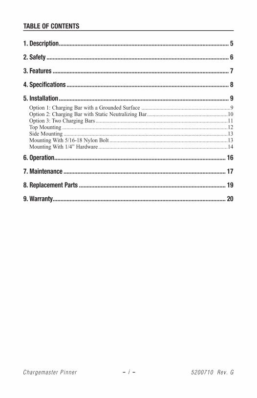
TABLE OF CONTENTS
1. Description .............................................................................................................. 5
2. Safety ...................................................................................................................... 6
3. Features .................................................................................................................. 7
4. Specifications ......................................................................................................... 8
5. Installation .............................................................................................................. 9Option 1: Charging Bar with a Grounded Surface ................................................................9Option 2: Charging Bar with Static Neutralizing Bar ..........................................................10Option 3: Two Charging Bars ...............................................................................................11Top Mounting .......................................................................................................................12Side Mounting ......................................................................................................................13Mounting With 5/16-18 Nylon Bolt .....................................................................................13Mounting With 1/4” Hardware .............................................................................................14
6. Operation ............................................................................................................... 16
7. Maintenance ......................................................................................................... 17
8. Replacement Parts ............................................................................................... 19
9. Warranty ................................................................................................................ 20

5200710 Rev . GChargemas te r P inner
(This page intentionally left blank)
1Chargemas te r P inner 5200710 Rev . G
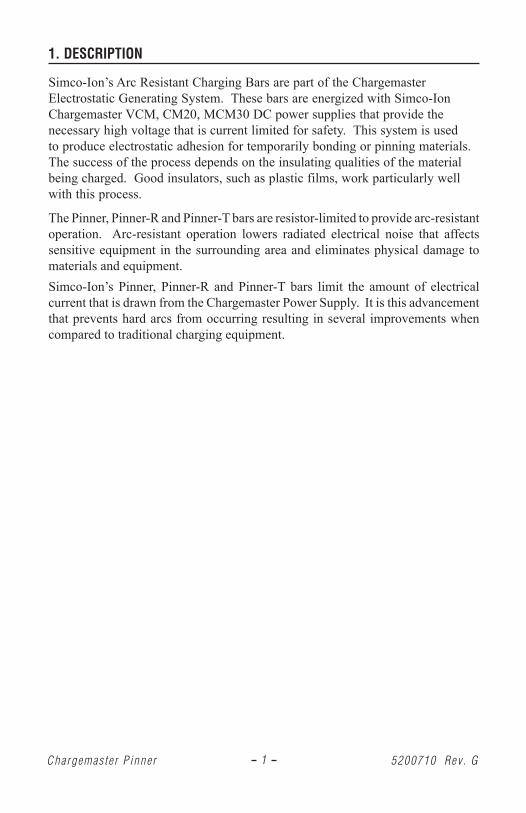
1. DESCRIPTION
Simco-Ion’s Arc Resistant Charging Bars are part of the Chargemaster Electrostatic Generating System. These bars are energized with Simco-Ion Chargemaster VCM, CM20, MCM30 DC power supplies that provide the necessary high voltage that is current limited for safety. This system is used to produce electrostatic adhesion for temporarily bonding or pinning materials. The success of the process depends on the insulating qualities of the material being charged. Good insulators, such as plastic films, work particularly well with this process.
The Pinner, Pinner-R and Pinner-T bars are resistor-limited to provide arc-resistant operation. Arc-resistant operation lowers radiated electrical noise that affects sensitive equipment in the surrounding area and eliminates physical damage to materials and equipment.Simco-Ion’s Pinner, Pinner-R and Pinner-T bars limit the amount of electrical current that is drawn from the Chargemaster Power Supply. It is this advancement that prevents hard arcs from occurring resulting in several improvements when compared to traditional charging equipment.
2Chargemas te r P inner 5200710 Rev . G
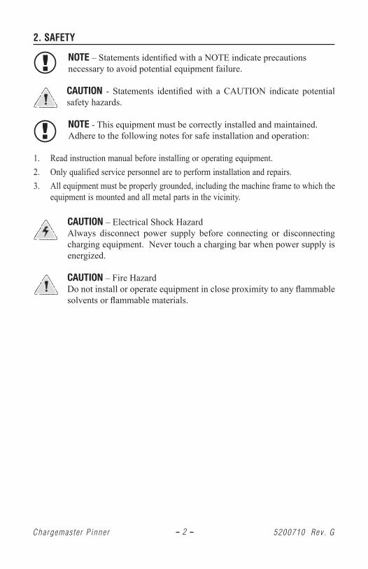
2. SAFETY
NOTE – Statements identified with a NOTE indicate precautions necessary to avoid potential equipment failure.
CAUTION - Statements identified with a CAUTION indicate potential safety hazards.
NOTE - This equipment must be correctly installed and maintained. Adhere to the following notes for safe installation and operation:
1. Read instruction manual before installing or operating equipment.2. Only qualified service personnel are to perform installation and repairs.3. All equipment must be properly grounded, including the machine frame to which the
equipment is mounted and all metal parts in the vicinity.
CAUTION – Electrical Shock Hazard Always disconnect power supply before connecting or disconnecting charging equipment. Never touch a charging bar when power supply is energized.
CAUTION – Fire Hazard Do not install or operate equipment in close proximity to any flammable solvents or flammable materials.
3Chargemas te r P inner 5200710 Rev . G
3. FEATURES
• Increased voltage consistency and pinning action.• Reduced EMI/RMI that can disturb sensitive electronic components.• Limited energy release that could otherwise degrade some plastics and other
materials causing additional damage and failures.
4Chargemas te r P inner 5200710 Rev . G
4. SPECIFICATIONS
INPUT VOLTAGE: ±30 kVDC (±50 kVDC with special mounting and insulation precautions)
OUTPUT CURRENT: 1.5mA/ft maxOPERATING ENVIRONMENT: 32°F (0°C) to 200°F (90°C); 70% RH Max, no
dewing permissibleOPERATING DISTANCE: 1/2” to 3” (application & voltage dependant)WEIGHT: 2.1 lb per foot DIMENSIONS: 3/4” W x 3-1/4” H x (EL + 2”) L
EL = Effective Length (6” to 144”; 3” mults)EMITTER MATERIAL: Pinner Bar: 316 Stainless Steel, Permanent,
Resistor Limited Pinner-R Bar: 316 Stainless Steel, Removeable/Replaceable, Resistor Limited Pinner-T Bar: Tungsten, Permanent, Resistor Limited
CASING MATERIAL: Glass filled vinylester (Rugged, impact resistant, light grey color)
HIGH VOLTAGE CABLE: Flexible, abrasion-resistant, silicone outer jacket rated to ±50 kV, 10-ft standard length (1/2” min bend radius)
5Chargemas te r P inner 5200710 Rev . G
5. INSTALLATION
UnpackingCarefully remove equipment from the carton and inspect the contents.
NOTE: If any damage has occurred during shipment, notify the local carrier at once. A report should also be forwarded to Simco-Ion, 2257 North Penn Road, Hatfield PA 19440. See Section 9 (Warranty) for Return Shipment information.
Determining Pinner Bar LocationAlthough Simco-Ion’s Pinner, Pinner-R and Pinner-T bars prevent hard arcs from occurring, the bars do exhibit a soft arcing that can be both useful in setting up the application and useful in keeping the system operational. As the distance between the Pinner Bar and ground reference is decreased, the first signs of electrical stress will be observed. The pins will start to display a purple glow and, in quiet surroundings, a slight sizzling buzz may also be heard as air molecules become stressed. Continuous operation in this condition will cause premature aging of the bar. Once the power supply is in position and operational, ensure that there is no purple glow at the emitter points. It is this purple glow that indicates the overstressed condition and that the bar is not providing its maximum possible pinning voltage.
CAUTION – Fire HazardDo not install or operate equipment in close proximity to any flammable solvents or flammable materials.
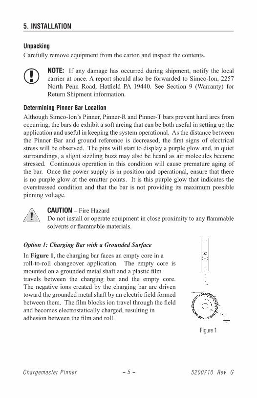
Option 1: Charging Bar with a Grounded Surface In Figure 1, the charging bar faces an empty core in a roll-to-roll changeover application. The empty core is mounted on a grounded metal shaft and a plastic film travels between the charging bar and the empty core. The negative ions created by the charging bar are driven toward the grounded metal shaft by an electric field formed between them. The film blocks ion travel through the field and becomes electrostatically charged, resulting in adhesion between the film and roll.
Figure 1
6Chargemas te r P inner 5200710 Rev . G
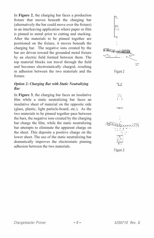
In Figure 2, the charging bar faces a production fixture that moves beneath the charging bar (alternatively the bar could move over the fixture) in an interleaving application where paper or film is pinned to metal prior to cutting and stacking. After the materials to be pinned together are positioned on the fixture, it moves beneath the charging bar. The negative ions created by the bar are driven toward the grounded metal fixture by an electric field formed between them. The top material blocks ion travel through the field and becomes electrostatically charged, resulting in adhesion between the two materials and the fixture.
Option 2: Charging Bar with Static Neutralizing BarIn Figure 3, the charging bar faces an insulative film while a static neutralizing bar faces an insulative sheet of material on the opposite side (glass, plastic, light particle-board, etc.). As the two materials to be pinned together pass between the bars, the negative ions created by the charging bar charge the film, while the static neutralizing bar attempts to eliminate the apparent charge on the sheet. This deposits a positive charge on the lower sheet. The use of the static neutralizing bar dramatically improves the electrostatic pinning adhesion between the two materials.
Figure 2
Figure 3
7Chargemas te r P inner 5200710 Rev . G
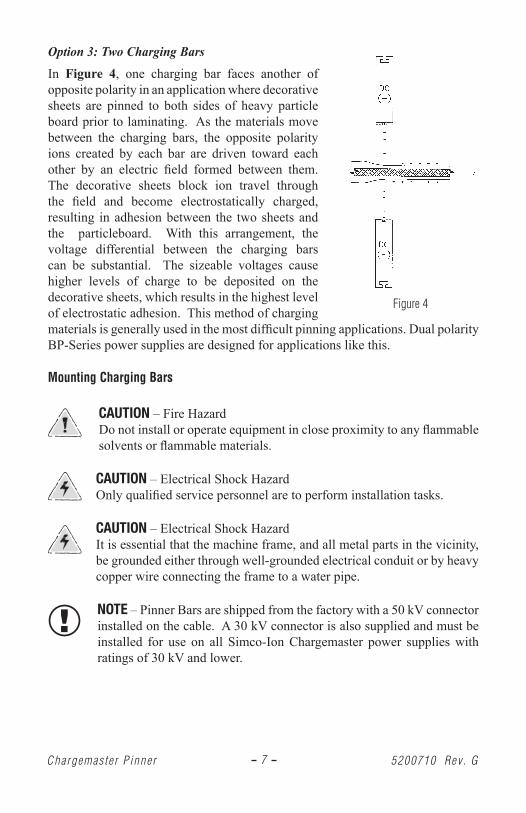
Option 3: Two Charging BarsIn Figure 4, one charging bar faces another of opposite polarity in an application where decorative sheets are pinned to both sides of heavy particle board prior to laminating. As the materials move between the charging bars, the opposite polarity ions created by each bar are driven toward each other by an electric field formed between them. The decorative sheets block ion travel through the field and become electrostatically charged, resulting in adhesion between the two sheets and the particleboard. With this arrangement, the voltage differential between the charging bars can be substantial. The sizeable voltages cause higher levels of charge to be deposited on the decorative sheets, which results in the highest level of electrostatic adhesion. This method of charging materials is generally used in the most difficult pinning applications. Dual polarity BP-Series power supplies are designed for applications like this.
Mounting Charging Bars
CAUTION – Fire Hazard Do not install or operate equipment in close proximity to any flammable solvents or flammable materials.
CAUTION – Electrical Shock HazardOnly qualified service personnel are to perform installation tasks.
CAUTION – Electrical Shock Hazard It is essential that the machine frame, and all metal parts in the vicinity, be grounded either through well-grounded electrical conduit or by heavy copper wire connecting the frame to a water pipe.
NOTE – Pinner Bars are shipped from the factory with a 50 kV connector installed on the cable. A 30 kV connector is also supplied and must be installed for use on all Simco-Ion Chargemaster power supplies with ratings of 30 kV and lower.
Figure 4
8Chargemas te r P inner 5200710 Rev . G
Determine the best location for the for guidance.
Multi-Function Bracket
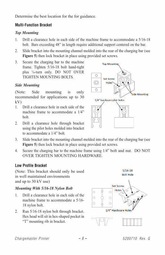
Top Mounting1. Drill a clearance hole in each side of the machine frame to accommodate a 5/16-18
bolt. Bars exceeding 48” in length require additional support centered on the bar.2. Slide bracket into the mounting channel molded into the rear of the charging bar (see
Figure 5) then lock bracket in place using provided set screws.3. Secure the charging bar to the machine
frame. Tighten 5/16-18 bolt hand-tight plus ¼-turn only. DO NOT OVER TIGHTEN MOUNTING BOLTS.
Side Mounting(Note: Side mounting is only recommended for applications up to 30 kV)1. Drill a clearance hole in each side of the
machine frame to accommodate a 1/4” bolt.
2. Drill a clearance hole through bracket using the pilot holes molded into bracket to accommodate a 1/4” bolt.
3. Slide bracket into the mounting channel molded into the rear of the charging bar (see Figure 5) then lock bracket in place using provided set screws.
4. Secure the charging bar to the machine frame using 1/4” bolt and nut. DO NOT OVER TIGHTEN MOUNTING HARDWARE.
Low Profile Bracket(Note: This bracket should only be used in well maintained environmentsand up to 30 kV use)
Mounting With 5/16-18 Nylon Bolt1. Drill a clearance hole in each side of the
machine frame to accommodate a 5/16-18 nylon bolt.
2. Run 5/16-18 nylon bolt through bracket. Hex head will sit in hex-shaped pocket in “T” mounting rib in bracket.
9Chargemas te r P inner 5200710 Rev . G
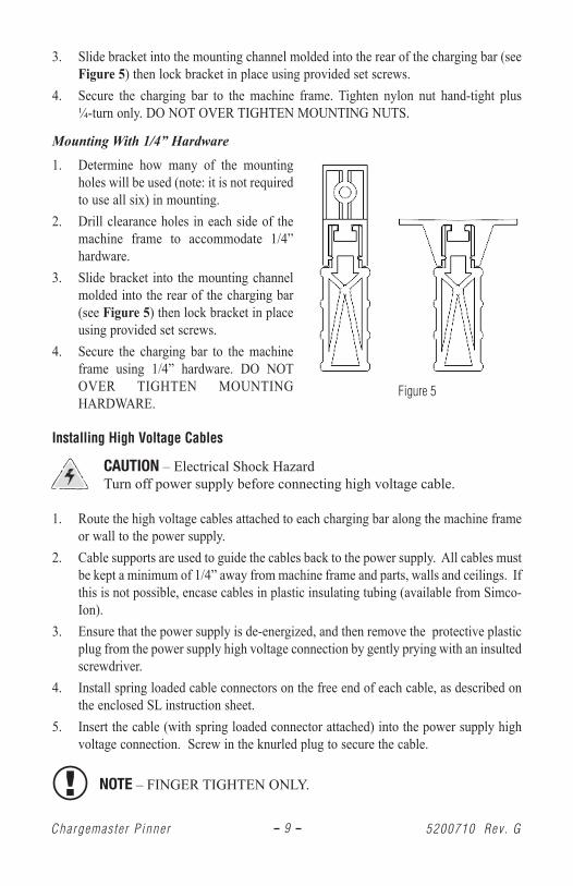
3. Slide bracket into the mounting channel molded into the rear of the charging bar (see Figure 5) then lock bracket in place using provided set screws.
4. Secure the charging bar to the machine frame. Tighten nylon nut hand-tight plus ¼-turn only. DO NOT OVER TIGHTEN MOUNTING NUTS.
Mounting With 1/4” Hardware1. Determine how many of the mounting
holes will be used (note: it is not required to use all six) in mounting.
2. Drill clearance holes in each side of the machine frame to accommodate 1/4” hardware.
3. Slide bracket into the mounting channel molded into the rear of the charging bar (see Figure 5) then lock bracket in place using provided set screws.
4. Secure the charging bar to the machine frame using 1/4” hardware. DO NOT OVER TIGHTEN MOUNTING HARDWARE.
Installing High Voltage Cables
CAUTION – Electrical Shock Hazard Turn off power supply before connecting high voltage cable.
1. Route the high voltage cables attached to each charging bar along the machine frame or wall to the power supply.
2. Cable supports are used to guide the cables back to the power supply. All cables must be kept a minimum of 1/4” away from machine frame and parts, walls and ceilings. If this is not possible, encase cables in plastic insulating tubing (available from Simco-Ion).
3. Ensure that the power supply is de-energized, and then remove the protective plastic plug from the power supply high voltage connection by gently prying with an insulted screwdriver.
4. Install spring loaded cable connectors on the free end of each cable, as described on the enclosed SL instruction sheet.
5. Insert the cable (with spring loaded connector attached) into the power supply high voltage connection. Screw in the knurled plug to secure the cable.
NOTE – FINGER TIGHTEN ONLY.
Figure 5
10Chargemas te r P inner 5200710 Rev . G
6. OPERATION
CAUTION – Electrical Shock Hazard Do not touch Charging Bar during operation.
CAUTION – Fire Hazard Do not operate equipment in close proximity to any flammable solvents or flammable materials.
1. Before energizing any power supply:• Ensure that all power supplies are properly grounded.• Ensure that all charging bars have been properly located, positioned and installed.• Ensure all requirements printed in the applicable power supply instructions have
been fully complied with.2. After the above checks have been performed, simply energize each power supply to
operate the charging bars.3. Setting Strength of Pinning:
• If charging bar is operating in electrical stress condition (evident by purple glow on pins and slight sizzling noise), slowly decrease operating voltage of the power supply.
• If adhesion or pinning strength is not adequate, slowly increase operating voltage of the power supply.
4. Always turn the power supply OFF when the system is not in use. For safety and ease of operation, it is recommended to connect the power supply line cord to the electrical system of the machine in such a manner that the power supply is only energized when the machine is in operation.
NOTE – Sustained operation in electrical stress will likely interfere with operation of the charging system. Electrical stress reduces output voltage from the power supply and suppresses the charging process. Sustained stressed operation may also damage the bar and power supply.
11Chargemas te r P inner 5200710 Rev . G
7. MAINTENANCE
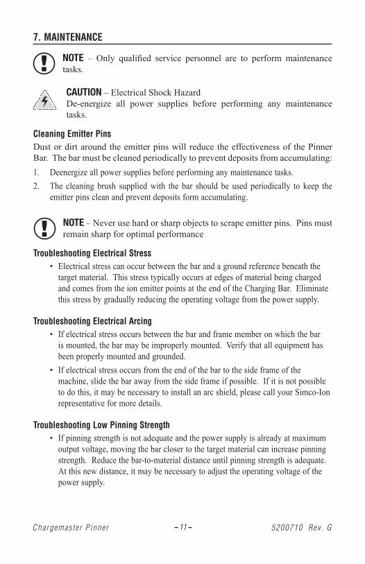
NOTE – Only qualified service personnel are to perform maintenance tasks.
CAUTION – Electrical Shock Hazard De-energize all power supplies before performing any maintenance tasks.
Cleaning Emitter PinsDust or dirt around the emitter pins will reduce the effectiveness of the Pinner Bar. The bar must be cleaned periodically to prevent deposits from accumulating:1. Deenergize all power supplies before performing any maintenance tasks.2. The cleaning brush supplied with the bar should be used periodically to keep the
emitter pins clean and prevent deposits form accumulating.
NOTE – Never use hard or sharp objects to scrape emitter pins. Pins must remain sharp for optimal performance
Troubleshooting Electrical Stress • Electrical stress can occur between the bar and a ground reference beneath the
target material. This stress typically occurs at edges of material being charged and comes from the ion emitter points at the end of the Charging Bar. Eliminate this stress by gradually reducing the operating voltage from the power supply.
Troubleshooting Electrical Arcing • If electrical stress occurs between the bar and frame member on which the bar
is mounted, the bar may be improperly mounted. Verify that all equipment has been properly mounted and grounded.
• If electrical stress occurs from the end of the bar to the side frame of the machine, slide the bar away from the side frame if possible. If it is not possible to do this, it may be necessary to install an arc shield, please call your Simco-Ion representative for more details.
Troubleshooting Low Pinning Strength • If pinning strength is not adequate and the power supply is already at maximum
output voltage, moving the bar closer to the target material can increase pinning strength. Reduce the bar-to-material distance until pinning strength is adequate. At this new distance, it may be necessary to adjust the operating voltage of the power supply.
12Chargemas te r P inner 5200710 Rev . G
• Low pinning strength may also be due to erosion of the emitter points. Sharp points promote the best ionization of air molecules. Inspect the emitter points, if they are visibly eroded or corroded follow these steps:
a) Remove contamination by brushing the emitter pins with a nonmetallic brush.b) If acceptable performance is not restored after cleaning, the pins of the Pinner-R
Bar should be replaced (NOTE- Emitter pins of the Pinner and Pinner-T Bar are NOT replaceable). Remove existing emitter pins using needle-nose pliers and replace with new pins in each socket.
c) If acceptable performance is not restored, contact Simco-Ion Customer Service at (215) 822-6401.
13Chargemas te r P inner 5200710 Rev . G
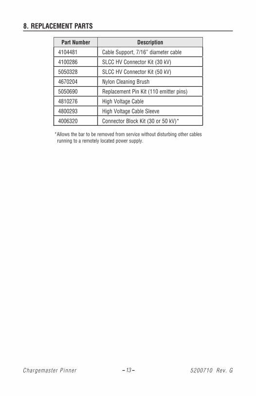
8. REPLACEMENT PARTS
Part Number Description
4104481 Cable Support, 7/16” diameter cable
4100286 SLCC HV Connector Kit (30 kV)
5050328 SLCC HV Connector Kit (50 kV)
4670204 Nylon Cleaning Brush
5050690 Replacement Pin Kit (110 emitter pins)
4810276 High Voltage Cable
4800293 High Voltage Cable Sleeve
4006320 Connector Block Kit (30 or 50 kV)*
*Allows the bar to be removed from service without disturbing other cables running to a remotely located power supply.
14Chargemas te r P inner 5200710 Rev . G
9. WARRANTY
Simco-Ion warrants its products to be free of defects in components, workmanship, or materials for a period of one year from date of purchase. This warranty does not apply to any physical or electrical damage caused by misuse, abuse or negligence (such as any modifications made to the unit or service work done by any other than Simco-Ion authorized technicians). Any unit with altered or removed serial number is ineligible for warranty.Simco-Ion will not be liable for loss or damage due directly or indirectly to an occurrence or use for which the product is not designed or intended. In no event shall Simco-Ion be liable for incidental or consequential damages except where state or regional laws override.This warranty extends to the original purchaser and is not transferable. No person, agent, distributor, dealer or company is authorized to change, modify, or amend the terms of this warranty in any manner whatsoever.All products returned must have an “RA” (Return Authorization) number regardless of warranty status. Call Simco-Ion for an assigned RA number.Information in this document is subject to change without notice and does not represent a commitment on the part of Simco-Ion. No part of this manual may be reproduced or transmitted in any form or by any means, electronic or mechanical, including photocopying and recording, for any purpose other than the purchaser’s personal use without written permission of Simco-Ion.

5200710 Rev . GChargemas te r P inner
(This page intentionally left blank)

5200710 Rev . GChargemas te r P inner
Simco-Ion2257 North Penn RoadHatfield, PA 19440 (215) 822-6401(800) [email protected]
© 2013 Simco-Ion. Printed in the U.S.A.