Embed Size (px)
Citation preview
___________________
___________________
___________________
___________________
___________________
___________________
___________________
___________________
___________________
SIMATIC NET
Industrial Ethernet switches SCALANCE XM-400
Operating Instructions
05/2017 C79000-G8976-C306-07
Introduction 1
Safety notices 2
Description of the device 3
Installation 4
Connecting up 5
Upkeep and maintenance 6
Technical specifications 7
Dimension drawings 8
Approvals A
Siemens AG Division Process Industries and Drives Postfach 48 48 90026 NÜRNBERG GERMANY
C79000-G8976-C306-07 Ⓟ 05/2017 Subject to change
Copyright © Siemens AG 2013 - 2017. All rights reserved
Legal information Warning notice system
This manual contains notices you have to observe in order to ensure your personal safety, as well as to prevent damage to property. The notices referring to your personal safety are highlighted in the manual by a safety alert symbol, notices referring only to property damage have no safety alert symbol. These notices shown below are graded according to the degree of danger.
DANGER indicates that death or severe personal injury will result if proper precautions are not taken.
WARNING indicates that death or severe personal injury may result if proper precautions are not taken.
CAUTION indicates that minor personal injury can result if proper precautions are not taken.
NOTICE indicates that property damage can result if proper precautions are not taken.
If more than one degree of danger is present, the warning notice representing the highest degree of danger will be used. A notice warning of injury to persons with a safety alert symbol may also include a warning relating to property damage.
Qualified Personnel The product/system described in this documentation may be operated only by personnel qualified for the specific task in accordance with the relevant documentation, in particular its warning notices and safety instructions. Qualified personnel are those who, based on their training and experience, are capable of identifying risks and avoiding potential hazards when working with these products/systems.
Proper use of Siemens products Note the following:
WARNING Siemens products may only be used for the applications described in the catalog and in the relevant technical documentation. If products and components from other manufacturers are used, these must be recommended or approved by Siemens. Proper transport, storage, installation, assembly, commissioning, operation and maintenance are required to ensure that the products operate safely and without any problems. The permissible ambient conditions must be complied with. The information in the relevant documentation must be observed.
Trademarks All names identified by ® are registered trademarks of Siemens AG. The remaining trademarks in this publication may be trademarks whose use by third parties for their own purposes could violate the rights of the owner.
Disclaimer of Liability We have reviewed the contents of this publication to ensure consistency with the hardware and software described. Since variance cannot be precluded entirely, we cannot guarantee full consistency. However, the information in this publication is reviewed regularly and any necessary corrections are included in subsequent editions.
SCALANCE XM-400 Operating Instructions, 05/2017, C79000-G8976-C306-07 3
Table of contents
1 Introduction ............................................................................................................................................. 5
2 Safety notices ......................................................................................................................................... 9
2.1 Security recommendations ..................................................................................................... 10
3 Description of the device ....................................................................................................................... 15
3.1 Product group ......................................................................................................................... 15
3.2 Product overview .................................................................................................................... 17
3.3 Accessories ............................................................................................................................. 18
3.4 Spare parts ............................................................................................................................. 21
3.5 Views....................................................................................................................................... 22 3.5.1 View of a SCALANCE XM408-4C .......................................................................................... 22 3.5.2 View of a SCALANCE XM408-8C device ............................................................................... 23 3.5.3 View of a SCALANCE XM416-4C device ............................................................................... 24
3.6 SELECT / SET button ............................................................................................................. 25
3.7 LED display ............................................................................................................................. 28 3.7.1 Overview ................................................................................................................................. 28 3.7.2 "RM" LED ................................................................................................................................ 28 3.7.3 "SB" LED ................................................................................................................................. 29 3.7.4 "F" LED ................................................................................................................................... 29 3.7.5 LEDs "DM1" and "DM2" .......................................................................................................... 29 3.7.6 LEDs "L1" and "L2" ................................................................................................................. 30 3.7.7 Port LEDs ................................................................................................................................ 31
3.8 C-PLUG/KEY-PLUG ............................................................................................................... 34 3.8.1 Function of the C-PLUG/KEY-PLUG ...................................................................................... 34 3.8.2 Replacing the C-PLUG/KEY-PLUG ........................................................................................ 35
3.9 Functions ................................................................................................................................ 37 3.9.1 Combo ports ........................................................................................................................... 37 3.9.2 Power over Ethernet (PoE) ..................................................................................................... 38 3.9.3 Near Field Communication ..................................................................................................... 39
4 Installation ............................................................................................................................................ 41
4.1 Safety notices for installation .................................................................................................. 41
4.2 Types of installation ................................................................................................................ 43
4.3 Mounting on DIN rails ............................................................................................................. 43
4.4 Installation on a standard S7-300 rail ..................................................................................... 44
4.5 Installation on a standard S7-1500 rail ................................................................................... 45
4.6 Fitting an extender .................................................................................................................. 46
4.7 General notes for SFP transceivers ........................................................................................ 49
Table of contents
SCALANCE XM-400 4 Operating Instructions, 05/2017, C79000-G8976-C306-07
5 Connecting up....................................................................................................................................... 51
5.1 Safety when connecting up .................................................................................................... 51
5.2 Spring-loaded terminal ........................................................................................................... 53
5.3 Power supply .......................................................................................................................... 54
5.4 Signaling contact .................................................................................................................... 55
5.5 Serial interface ....................................................................................................................... 56
5.6 Out-of-band interface ............................................................................................................. 58
5.7 Functional ground .................................................................................................................. 59
6 Upkeep and maintenance ..................................................................................................................... 61
6.1 Downloading new firmware using TFTP without WBM and CLI ............................................ 61
6.2 Restoring the factory settings ................................................................................................ 62
7 Technical specifications ........................................................................................................................ 63
7.1 Technical specifications of the SCALANCE XM408-4C ........................................................ 63
7.2 Technical specifications of the SCALANCE XM408-8C ........................................................ 64
7.3 Technical specifications of the SCALANCE XM416-4C ........................................................ 66
7.4 Switching properties ............................................................................................................... 67
8 Dimension drawings .............................................................................................................................. 69
8.1 SCALANCE XM-400 dimension drawings ............................................................................. 69
8.2 Extender dimension drawings ................................................................................................ 71
A Approvals ............................................................................................................................................. 75
Index .................................................................................................................................................... 81
SCALANCE XM-400 Operating Instructions, 05/2017, C79000-G8976-C306-07 5
Introduction 1
Purpose of the Operating Instructions These operating instructions support you when installing and connecting up devices of the SCALANCE XM-400 product group.
The configuration and the integration of the device in a network are not described in these operating instructions.
Validity of the Operating Instructions These operating instructions apply to the following devices:
● SCALANCE XM408-4C
● SCALANCE XM408-8C
● SCALANCE XM416-4C
Unless mentioned otherwise, the descriptions in these operating instructions refer to all devices of the SCALANCE XM-400 product group named above in the section on validity.
Designations used Classification Description Terms used Product line The product line includes all devices and variants of all product groups.
If information applies to all product groups within the product line, the term SCALANCE X-400 is used.
SCALANCE X-400
Product group If information applies to all devices and variants of a product group, the term SCALANCE XM-400 is used.
SCALANCE XM-400
Device If information relates to a specific device, the device name is used. SCALANCE XM408-4C SCALANCE XM408-8C SCALANCE XM416-4C
Additional documentation In addition, note the Operating Instructions of the extenders and pluggable transceivers.
When working with the port extender PE408PoE, note the documentation of the PoE power supplies SCALANCE PS9230 PoE and SCALANCE PS924 PoE.
When using the Function Extender BUS ANALYZER Agent XM-400, note the documentation of the BUS ANALYZER Agent XM-400.
Introduction
SCALANCE XM-400 6 Operating Instructions, 05/2017, C79000-G8976-C306-07
You will find the supplementary documentation here:
● On the data medium that ships with some products:
– Product CD / product DVD
– SIMATIC NET Manual Collection
● On the Internet pages of Siemens Industry Online Support (http://support.automation.siemens.com/WW/view/en/79730528/133300)
Documentation on configuration You will find detailed information on configuring the devices in the following configuration manuals:
● SCALANCE XM-400/XR-500 Web Based Management
● SCALANCE XM-400/XR-500 Command Line Interface
You will find the configuration manuals here:
● On the data medium that ships with some products:
– Product CD / product DVD
– SIMATIC NET Manual Collection
● On the Internet pages of Siemens Industry Online Support. (http://support.automation.siemens.com/WW/view/en/79730528/130000)
Further documentation In the system manuals "Industrial Ethernet / PROFINET Industrial Ethernet" and "Industrial Ethernet / PROFINET passive network components", you will find information on other SIMATIC NET products that you can operate along with the devices of this product line in an Industrial Ethernet network.
There, you will find among other things optical performance data of the communications partner that you require for the installation.
You will find the system manuals here:
● On the data medium that ships with some products:
– Product CD / product DVD
– SIMATIC NET Manual Collection
● On the Internet pages of Siemens Industry Online Support under the following entry IDs:
– 27069465 (http://support.automation.siemens.com/WW/view/en/27069465) Industrial Ethernet / PROFINET Industrial Ethernet System Manual
– 84922825 (http://support.automation.siemens.com/WW/view/en/84922825) Industrial Ethernet / PROFINET - Passive network components System Manual

Introduction
SCALANCE XM-400 Operating Instructions, 05/2017, C79000-G8976-C306-07 7
SIMATIC NET manuals You will find the SIMATIC NET manuals here:
● On the data medium that ships with some products:
– Product CD / product DVD
– SIMATIC NET Manual Collection
● On the Internet pages of Siemens Industry Online Support (http://support.automation.siemens.com/WW/view/en/10805878/130000).
SIMATIC NET glossary Explanations of many of the specialist terms used in this documentation can be found in the SIMATIC NET glossary.
You will find the SIMATIC NET glossary here:
● SIMATIC NET Manual Collection or product DVD
The DVD ships with certain SIMATIC NET products.
● On the Internet under the following address:
50305045 (http://support.automation.siemens.com/WW/view/en/50305045)
Catalogs You will find the article numbers for the Siemens products of relevance here in the following catalogs:
● SIMATIC NET Industrial Communication / Industrial Identification, catalog IK PI
● SIMATIC Products for Totally Integrated Automation and Micro Automation, catalog ST 70
● Industry Mall - catalog and ordering system for automation and drive technology, Online catalog (https://mall.industry.siemens.com/goos/WelcomePage.aspx?regionUrl=/de&language=en)
You can request the catalogs and additional information from your Siemens representative.
Security information Siemens provides products and solutions with industrial security functions that support the secure operation of plants, systems, machines and networks.
In order to protect plants, systems, machines and networks against cyber threats, it is necessary to implement – and continuously maintain – a holistic, state-of-the-art industrial security concept. Siemens’ products and solutions only form one element of such a concept.
Customer is responsible to prevent unauthorized access to its plants, systems, machines and networks. Systems, machines and components should only be connected to the enterprise network or the internet if and to the extent necessary and with appropriate security measures (e.g. use of firewalls and network segmentation) in place.
Introduction
SCALANCE XM-400 8 Operating Instructions, 05/2017, C79000-G8976-C306-07
Additionally, Siemens’ guidance on appropriate security measures should be taken into account. For more information about industrial security, please visit http://www.siemens.com/industrialsecurity (http://www.siemens.com/industrialsecurity)
Siemens’ products and solutions undergo continuous development to make them more secure. Siemens strongly recommends to apply product updates as soon as available and to always use the latest product versions. Use of product versions that are no longer supported, and failure to apply latest updates may increase customer’s exposure to cyber threats.
To stay informed about product updates, subscribe to the Siemens Industrial Security RSS Feed under https://support.industry.siemens.com/cs/ww/en/ps/15247/pm (https://support.industry.siemens.com/cs/ww/en/ps/15247/pm).
Unpacking and checking
WARNING
Do not use any parts that show evidence of damage
If you use damaged parts, there is no guarantee that the device will function according to the specification.
If you use damaged parts, this can lead to the following problems: • Injury to persons • Loss of the approvals • Violation of the EMC regulations • Damage to the device and other components
Use only undamaged parts.
1. Make sure that the package is complete.
2. Check all the parts for transport damage.
SCALANCE XM-400 Operating Instructions, 05/2017, C79000-G8976-C306-07 9
Safety notices 2
Read the safety notices Note the following safety notices. These relate to the entire working life of the device.
You should also read the safety notices relating to handling in the individual sections, particularly in the sections "Installation" and "Connecting up".
Safety notices on use in hazardous areas
General safety notices relating to protection against explosion
WARNING
EXPLOSION HAZARD
Do not open the device when the supply voltage is turned on.
Safety notices when using the device according to Hazardous Locations (HazLoc)
If you use the device under HazLoc conditions you must also keep to the following safety notices in addition to the general safety notices for protection against explosion:
This equipment is suitable for use in Class I, Division 2, Groups A, B, C and D or non-hazardous locations only.
This equipment is suitable for use in Class I, Zone 2, Group IIC or non-hazardous locations only.
Safety notices 2.1 Security recommendations
SCALANCE XM-400 10 Operating Instructions, 05/2017, C79000-G8976-C306-07
2.1 Security recommendations
NOTICE
Information security
Connect to the device and change the standard password for the user set in the factory "admin" and "" before you operate the device.
To prevent unauthorized access, note the following security recommendations.
General ● You should make regular checks to make sure that the device meets these
recommendations and/or other security guidelines.
● Evaluate your plant as a whole in terms of security. Use a cell protection concept with suitable products (http://www.industry.siemens.com/topics/global/en/industrial-security/network-security/Pages/Default.aspx).
● When the internal and external network are disconnected, an attacker cannot access internal data from the outside. Therefore operate the device only within a protected network area.
● For communication via non-secure networks use additional devices with VPN functionality to encrypt and authenticate the communication.
● Terminate management connections correctly (WBM. Telnet, SSH etc.).
Physical access ● Restrict physical access to the device to qualified personnel.
– The memory card or the PLUG (C-PLUG, KEY-PLUG) contains sensitive data such as certificates, keys etc. that can be read out and modified.
– Using the button, you can reset the device to the factory defaults.
● If the device is publicly accessible, disable the functions of the button using the software.
● Lock unused physical ports on the device. Unused ports can be used to gain forbidden access to the plant.
Software (security functions) ● Keep the firmware up to date. Check regularly for security updates for the device. You will
find information on this on the Internet pages Industrial Security (http://www.siemens.com/industrialsecurity).
● Inform yourself regularly about security recommendations by Siemens ProductCERT (http://www.siemens.com/cert/en/cert-security-advisories.htm).
● Only activate protocols that you require to use the device.
Safety notices 2.1 Security recommendations
SCALANCE XM-400 Operating Instructions, 05/2017, C79000-G8976-C306-07 11
● Restrict access to the management of the device with rules in an access control list (ACL).
● The option of VLAN structuring provides protection against DoS attacks and unauthorized access. Check whether this is practical or useful in your environment.
● Use a central logging server to log changes and accesses. Operate your logging server within the protected network area and check the logging information regularly.
Passwords ● Define rules for the assignment of passwords.
● Regularly change your passwords to increase security.
● Use passwords with a high password strength.
● Make sure that all passwords are protected and inaccessible to unauthorized persons.
● Do not use the same password for different users and systems.
Certificates and keys ● On the device there is a preset SSL certificate with key. Replace this certificate with a
self-made certificate with key. We recommend that you use a certificate signed either by a reliable external or by an internal certification authority.
● Use a certification authority including key revocation and management to sign certificates.
● Make sure that user-defined private keys are protected and inaccessible to unauthorized persons.
● It is recommended that you use password-protected certificates in the PKCS #12 format
● Verify certificates and fingerprints on the server and client to prevent "man in the middle" attacks.
● It is recommended that you use certificates with a key length of at least 2048 bits.
● Change certificates and keys immediately, if there is a suspicion of compromise.
Safety notices 2.1 Security recommendations
SCALANCE XM-400 12 Operating Instructions, 05/2017, C79000-G8976-C306-07
Secure/non-secure protocols and services ● Avoid or disable non-secure protocols and services, for example HTTP, Telnet and TFTP.
For historical reasons, these protocols are available, however not intended for secure applications. Use non-secure protocols on the device with caution.
● Check whether use of the following protocols and services is necessary:
– Non authenticated and unencrypted ports
– MRP, HRP
– IGMP snooping
– LLDP
– Syslog
– RADIUS
– DHCP Options 66/67
– TFTP
– GMRP and GVRP
● The following protocols provide secure alternatives:
– HTTP → HTTPS
– Telnet → SSH
– SNMPv1/v2c → SNMPv3
Check whether use of SNMPv1/v2c. is necessary. SNMPv1/v2c is classified as non-secure. Use the option of preventing write access. The device provides you with suitable setting options.
If SNMP is enabled, change the community names. If no unrestricted access is necessary, restrict access with SNMP.
Use the authentication and encryption mechanisms of SNMPv3.
● Use secure protocols when access to the device is not prevented by physical protection measures.
● If you require non-secure protocols and services, operate the device only within a protected network area.
● Restrict the services and protocols available to the outside to a minimum.
● For the DCP function, enable the "Read Only" mode after commissioning.
● If you use RADIUS for management access to the device, activate secure protocols and services.
Interfaces security ● Disable unused interfaces.
● Use IEEE 802.1X for interface authentication.
● Use the function "Locked Ports" to block interfaces for unknown nodes.
Safety notices 2.1 Security recommendations
SCALANCE XM-400 Operating Instructions, 05/2017, C79000-G8976-C306-07 13
● Use the configuration options of the interfaces, e.g. the "Edge Type".
● Configure the receive ports so that they discard all untagged frames ("Tagged Frames Only").
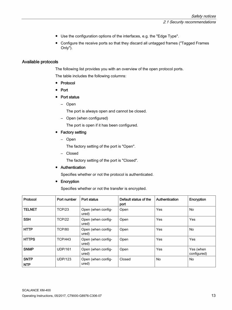
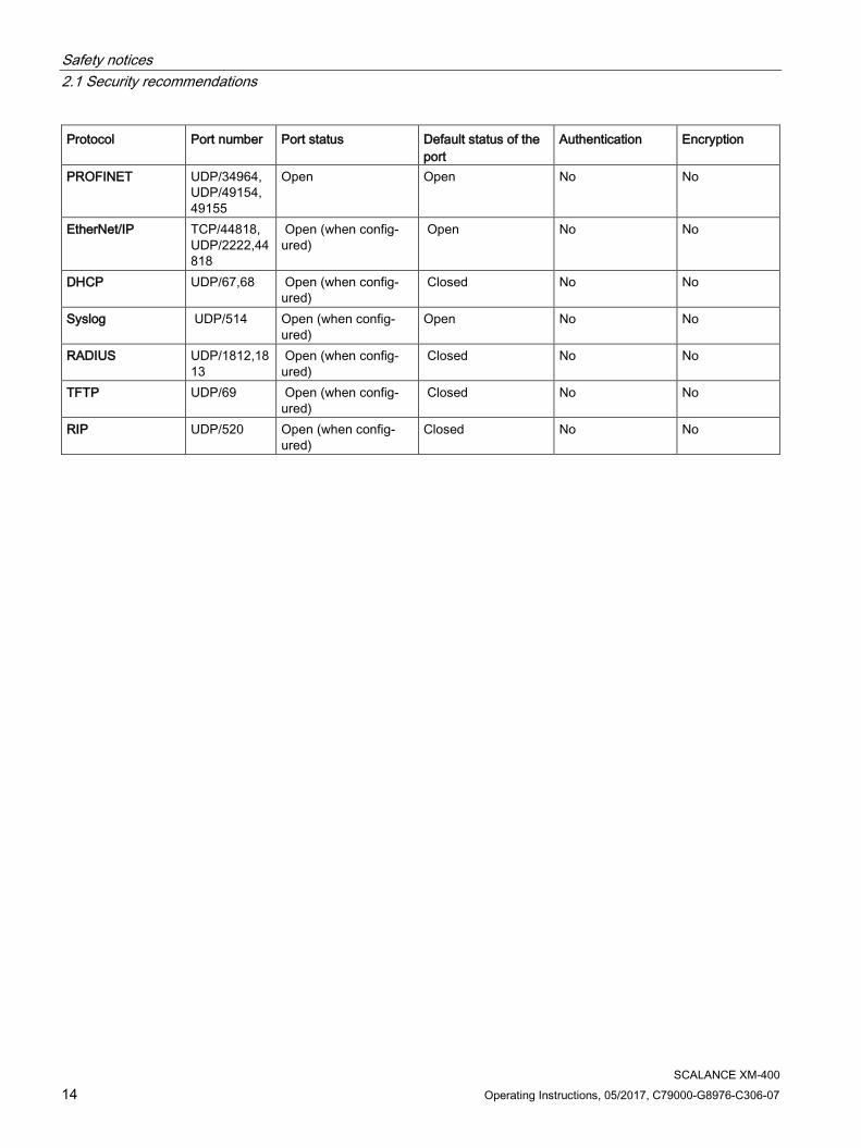
Available protocols The following list provides you with an overview of the open protocol ports.
The table includes the following columns:
● Protocol
● Port
● Port status
– Open
The port is always open and cannot be closed.
– Open (when configured)
The port is open if it has been configured.
● Factory setting
– Open
The factory setting of the port is "Open".
– Closed
The factory setting of the port is "Closed".
● Authentication
Specifies whether or not the protocol is authenticated.
● Encryption
Specifies whether or not the transfer is encrypted. Protocol Port number Port status Default status of the
port Authentication Encryption
TELNET TCP/23 Open (when config-ured)
Open Yes No
SSH TCP/22 Open (when config-ured)
Open Yes Yes
HTTP TCP/80 Open (when config-ured)
Open Yes No
HTTPS TCP/443 Open (when config-ured)
Open Yes Yes
SNMP UDP/161 Open (when config-ured)
Open Yes Yes (when configured)
SNTP NTP
UDP/123 Open (when config-ured)
Closed No No
Safety notices 2.1 Security recommendations
SCALANCE XM-400 14 Operating Instructions, 05/2017, C79000-G8976-C306-07
Protocol Port number Port status Default status of the port
Authentication Encryption
PROFINET UDP/34964, UDP/49154, 49155
Open Open No No
EtherNet/IP TCP/44818, UDP/2222,44818
Open (when config-ured)
Open No No
DHCP UDP/67,68 Open (when config-ured)
Closed No No
Syslog UDP/514 Open (when config-ured)
Open No No
RADIUS UDP/1812,1813
Open (when config-ured)
Closed No No
TFTP UDP/69 Open (when config-ured)
Closed No No
RIP UDP/520 Open (when config-ured)
Closed No No
SCALANCE XM-400 Operating Instructions, 05/2017, C79000-G8976-C306-07 15
Description of the device 3 3.1 Product group
SCALANCE XM-400 product group The product group SCALANCE XM-400 consists of basic devices (compact switches) and extenders (port extenders and function extender).
SCALANCE XM-400 basic device
Basic properties
The SCALANCE XM-400 basic devices are modular compact switches with fixed RJ-45 ports (10/100/1000 Mbps) and SFP transceiver slots that can be equipped individually. The SFP transceiver slots are combo ports.
A SCALANCE XM-400 can manage a maximum of 24 ports with 10/100/1000 Mbps.
The following components exist only on the basic device:
● CPU
● Power supply
● Signaling contact
● Out-of-band port
● Serial interface
● "SELECT / SET" button
Expansions
The basic devices can be expanded with additional ports and functions by using an extender. The extenders are connected to the side of the basic device. Each basic device has an expansion interface to the left for function extenders and to the right an expansion interface for port extenders.
Depending on the number of ports of the basic device (10/100/1000 Mbps) up to 2 port extenders can be added. Further port extenders are not supplied with power. There is no particular order in which the port extenders need to be added.
Example:
● The basic device SCALANCE XM408-8C has 8 ports. It can therefore be expanded by 2 port extenders each with 8 ports.
● The basic device SCALANCE XM416-4C has 16 ports. It can therefore be expanded by one port extender with 8 ports.
A function extender can be added.
Description of the device 3.1 Product group
SCALANCE XM-400 16 Operating Instructions, 05/2017, C79000-G8976-C306-07
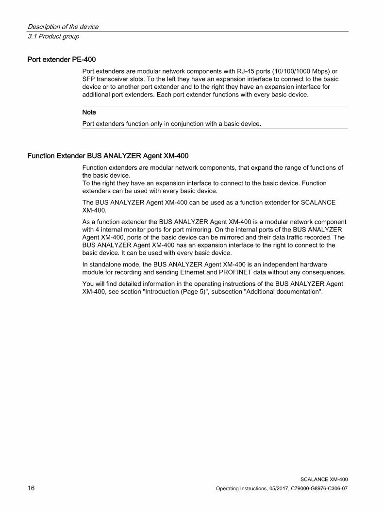
Port extender PE-400 Port extenders are modular network components with RJ-45 ports (10/100/1000 Mbps) or SFP transceiver slots. To the left they have an expansion interface to connect to the basic device or to another port extender and to the right they have an expansion interface for additional port extenders. Each port extender functions with every basic device.
Note
Port extenders function only in conjunction with a basic device.
Function Extender BUS ANALYZER Agent XM-400 Function extenders are modular network components, that expand the range of functions of the basic device. To the right they have an expansion interface to connect to the basic device. Function extenders can be used with every basic device.
The BUS ANALYZER Agent XM-400 can be used as a function extender for SCALANCE XM-400.
As a function extender the BUS ANALYZER Agent XM-400 is a modular network component with 4 internal monitor ports for port mirroring. On the internal ports of the BUS ANALYZER Agent XM-400, ports of the basic device can be mirrored and their data traffic recorded. The BUS ANALYZER Agent XM-400 has an expansion interface to the right to connect to the basic device. It can be used with every basic device.
In standalone mode, the BUS ANALYZER Agent XM-400 is an independent hardware module for recording and sending Ethernet and PROFINET data without any consequences.
You will find detailed information in the operating instructions of the BUS ANALYZER Agent XM-400, see section "Introduction (Page 5)", subsection "Additional documentation".
Description of the device 3.2 Product overview
SCALANCE XM-400 Operating Instructions, 05/2017, C79000-G8976-C306-07 17
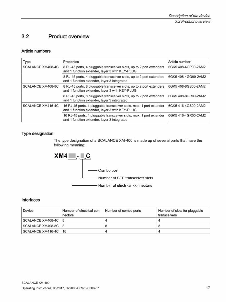
3.2 Product overview
Article numbers Type Properties Article number SCALANCE XM408-4C 8 RJ-45 ports, 4 pluggable transceiver slots, up to 2 port extenders
and 1 function extender, layer 3 with KEY-PLUG 6GK5 408-4GP00-2AM2
8 RJ-45 ports, 4 pluggable transceiver slots, up to 2 port extenders and 1 function extender, layer 3 integrated
6GK5 408-4GQ00-2AM2
SCALANCE XM408-8C 8 RJ-45 ports, 8 pluggable transceiver slots, up to 2 port extenders and 1 function extender, layer 3 with KEY-PLUG
6GK5 408-8GS00-2AM2
8 RJ-45 ports, 8 pluggable transceiver slots, up to 2 port extenders and 1 function extender, layer 3 integrated
6GK5 408-8GR00-2AM2
SCALANCE XM416-4C 16 RJ-45 ports, 4 pluggable transceiver slots, max. 1 port extender and 1 function extender, layer 3 with KEY-PLUG
6GK5 416-4GS00-2AM2
16 RJ-45 ports, 4 pluggable transceiver slots, max. 1 port extender and 1 function extender, layer 3 integrated
6GK5 416-4GR00-2AM2
Type designation The type designation of a SCALANCE XM-400 is made up of several parts that have the following meaning:
Interfaces Device Number of electrical con-
nectors Number of combo ports Number of slots for pluggable
transceivers SCALANCE XM408-4C 8 4 4 SCALANCE XM408-8C 8 8 8 SCALANCE XM416-4C 16 4 4
Description of the device 3.3 Accessories
SCALANCE XM-400 18 Operating Instructions, 05/2017, C79000-G8976-C306-07
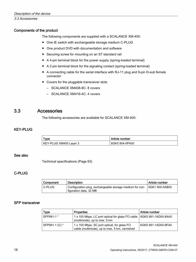
Components of the product The following components are supplied with a SCALANCE XM-400:
● One IE switch with exchangeable storage medium C-PLUG
● One product DVD with documentation and software
● Securing screw for mounting on an S7 standard rail
● A 4-pin terminal block for the power supply (spring-loaded terminal)
● A 2-pin terminal block for the signaling contact (spring-loaded terminal)
● A connecting cable for the serial interface with RJ-11 plug and 9-pin D-sub female connector
● Covers for the pluggable transceiver slots
– SCALANCE XM408-8C: 8 covers
– SCALANCE XM416-4C: 4 covers
3.3 Accessories The following accessories are available for SCALANCE XM-400:
KEY-PLUG Type Article number KEY-PLUG XM400 Layer 3 6GK5 904-0PA00
See also Technical specifications (Page 63)
C-PLUG Component Description Article number C-PLUG Configuration plug, exchangeable storage medium for con-
figuration data, 32 MB 6GK1 900-0AB00
SFP transceiver Type Properties Article number SFP991-1 * 1 x 100 Mbps, LC port optical for glass FO cable
(multimode), up to max. 5 km 6GK5 991-1AD00-8AA0
SFP991-1 (C) * 1 x 100 Mbps, SC port optical, for glass FO cable (multimode), up to max. 5 km, varnished
6GK5 991-1AD00-8FA0
Description of the device 3.3 Accessories
SCALANCE XM-400 Operating Instructions, 05/2017, C79000-G8976-C306-07 19
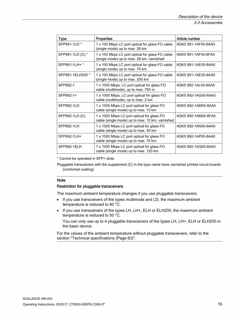
Type Properties Article number SFP991-1LD * 1 x 100 Mbps LC port optical for glass FO cable
(single mode) up to max. 26 km 6GK5 991-1AF00-8AA0
SFP991-1LD (C) * 1 x 100 Mbps LC port optical for glass FO cable (single mode) up to max. 26 km, varnished
6GK5 991-1AF00-8FA0
SFP991-1LH+ * 1 x 100 Mbps LC port optical for glass FO cable (single mode) up to max. 70 km
6GK5 991-1AE00-8AA0
SFP991-1ELH200 * 1 x 100 Mbps LC port optical for glass FO cable (single mode) up to max. 200 km
6GK5 991-1AE30-8AA0
SFP992-1 1 x 1000 Mbps, LC port optical for glass FO cable (multimode), up to max. 750 m
6GK5 992-1AL00-8AA0
SFP992-1+ 1 x 1000 Mbps, LC port optical for glass FO cable (multimode), up to max. 2 km
6GK5 992-1AG00-8AA0
SFP992-1LD 1 x 1000 Mbps LC port optical for glass FO cable (single mode) up to max. 10 km
6GK5 992-1AM00-8AA0
SFP992-1LD (C) 1 x 1000 Mbps LC port optical for glass FO cable (single mode) up to max. 10 km, varnished
6GK5 992-1AM00-8FA0
SFP992-1LH 1 x 1000 Mbps LC port optical for glass FO cable (single mode) up to max. 40 km
6GK5 992-1AN00-8AA0
SFP992-1LH+ 1 x 1000 Mbps LC port optical for glass FO cable (single mode) up to max. 70 km
6GK5 992-1AP00-8AA0
SFP992-1ELH 1 x 1000 Mbps LC port optical for glass FO cable (single mode) up to max. 120 km
6GK5 992-1AQ00-8AA0
* Cannot be operated in SFP+ slots. Pluggable transceivers with the supplement (C) in the type name have varnished printed circuit boards
(conformal coating).
Note Restriction for pluggable transceivers
The maximum ambient temperature changes if you use pluggable transceivers: • If you use transceivers of the types multimode and LD, the maximum ambient
temperature is reduced to 60 °C. • If you use transceivers of the types LH, LH+, ELH or ELH200, the maximum ambient
temperature is reduced to 50 °C. You can only use up to 4 pluggable transceivers of the types LH, LH+, ELH or ELH200 in the basic device.
For the values of the ambient temperature without pluggable transceivers, refer to the section "Technical specifications (Page 63)".
Description of the device 3.3 Accessories
SCALANCE XM-400 20 Operating Instructions, 05/2017, C79000-G8976-C306-07
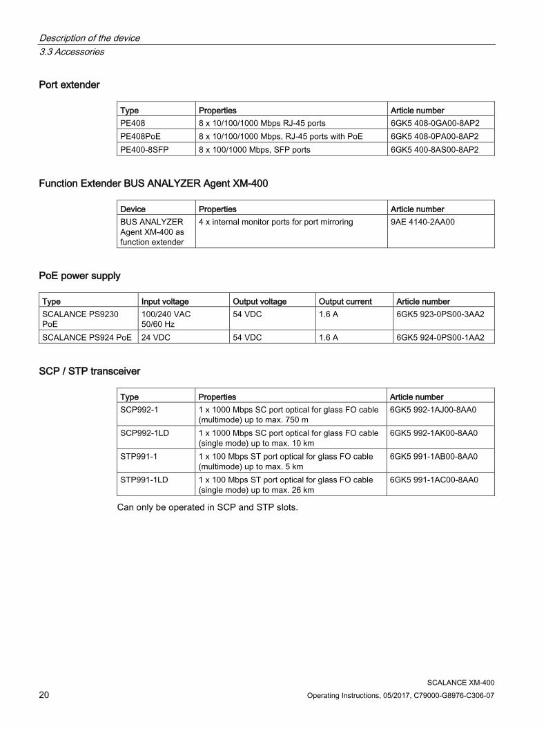
Port extender Type Properties Article number PE408 8 x 10/100/1000 Mbps RJ-45 ports 6GK5 408-0GA00-8AP2 PE408PoE 8 x 10/100/1000 Mbps, RJ-45 ports with PoE 6GK5 408-0PA00-8AP2 PE400-8SFP 8 x 100/1000 Mbps, SFP ports 6GK5 400-8AS00-8AP2
Function Extender BUS ANALYZER Agent XM-400 Device Properties Article number BUS ANALYZER Agent XM-400 as function extender
4 x internal monitor ports for port mirroring 9AE 4140-2AA00
PoE power supply Type Input voltage Output voltage Output current Article number SCALANCE PS9230 PoE
100/240 VAC 50/60 Hz
54 VDC 1.6 A 6GK5 923-0PS00-3AA2
SCALANCE PS924 PoE 24 VDC 54 VDC 1.6 A 6GK5 924-0PS00-1AA2
SCP / STP transceiver Type Properties Article number SCP992-1 1 x 1000 Mbps SC port optical for glass FO cable
(multimode) up to max. 750 m 6GK5 992-1AJ00-8AA0
SCP992-1LD 1 x 1000 Mbps SC port optical for glass FO cable (single mode) up to max. 10 km
6GK5 992-1AK00-8AA0
STP991-1 1 x 100 Mbps ST port optical for glass FO cable (multimode) up to max. 5 km
6GK5 991-1AB00-8AA0
STP991-1LD 1 x 100 Mbps ST port optical for glass FO cable (single mode) up to max. 26 km
6GK5 991-1AC00-8AA0
Can only be operated in SCP and STP slots.
Description of the device 3.4 Spare parts
SCALANCE XM-400 Operating Instructions, 05/2017, C79000-G8976-C306-07 21
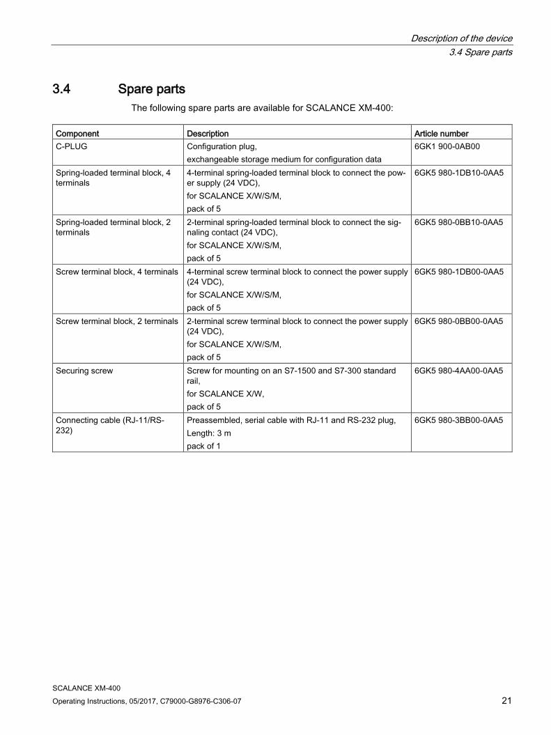
3.4 Spare parts The following spare parts are available for SCALANCE XM-400:
Component Description Article number C-PLUG Configuration plug,
exchangeable storage medium for configuration data 6GK1 900-0AB00
Spring-loaded terminal block, 4 terminals
4-terminal spring-loaded terminal block to connect the pow-er supply (24 VDC), for SCALANCE X/W/S/M, pack of 5
6GK5 980-1DB10-0AA5
Spring-loaded terminal block, 2 terminals
2-terminal spring-loaded terminal block to connect the sig-naling contact (24 VDC), for SCALANCE X/W/S/M, pack of 5
6GK5 980-0BB10-0AA5
Screw terminal block, 4 terminals 4-terminal screw terminal block to connect the power supply (24 VDC), for SCALANCE X/W/S/M, pack of 5
6GK5 980-1DB00-0AA5
Screw terminal block, 2 terminals 2-terminal screw terminal block to connect the power supply (24 VDC), for SCALANCE X/W/S/M, pack of 5
6GK5 980-0BB00-0AA5
Securing screw Screw for mounting on an S7-1500 and S7-300 standard rail, for SCALANCE X/W, pack of 5
6GK5 980-4AA00-0AA5
Connecting cable (RJ-11/RS-232)
Preassembled, serial cable with RJ-11 and RS-232 plug, Length: 3 m pack of 1
6GK5 980-3BB00-0AA5
Description of the device 3.5 Views
SCALANCE XM-400 22 Operating Instructions, 05/2017, C79000-G8976-C306-07
3.5 Views
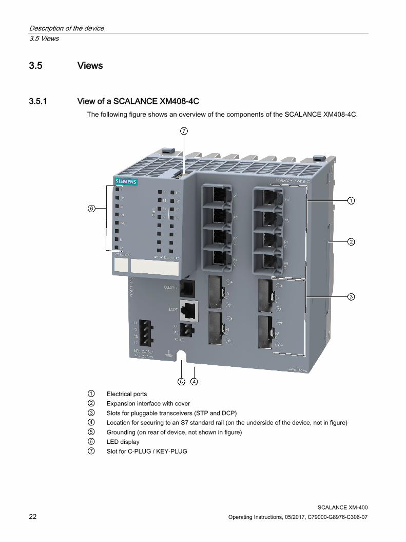
3.5.1 View of a SCALANCE XM408-4C The following figure shows an overview of the components of the SCALANCE XM408-4C.
① Electrical ports ② Expansion interface with cover ③ Slots for pluggable transceivers (STP and DCP) ④ Location for securing to an S7 standard rail (on the underside of the device, not in figure) ⑤ Grounding (on rear of device, not shown in figure) ⑥ LED display ⑦ Slot for C-PLUG / KEY-PLUG
Description of the device 3.5 Views
SCALANCE XM-400 Operating Instructions, 05/2017, C79000-G8976-C306-07 23
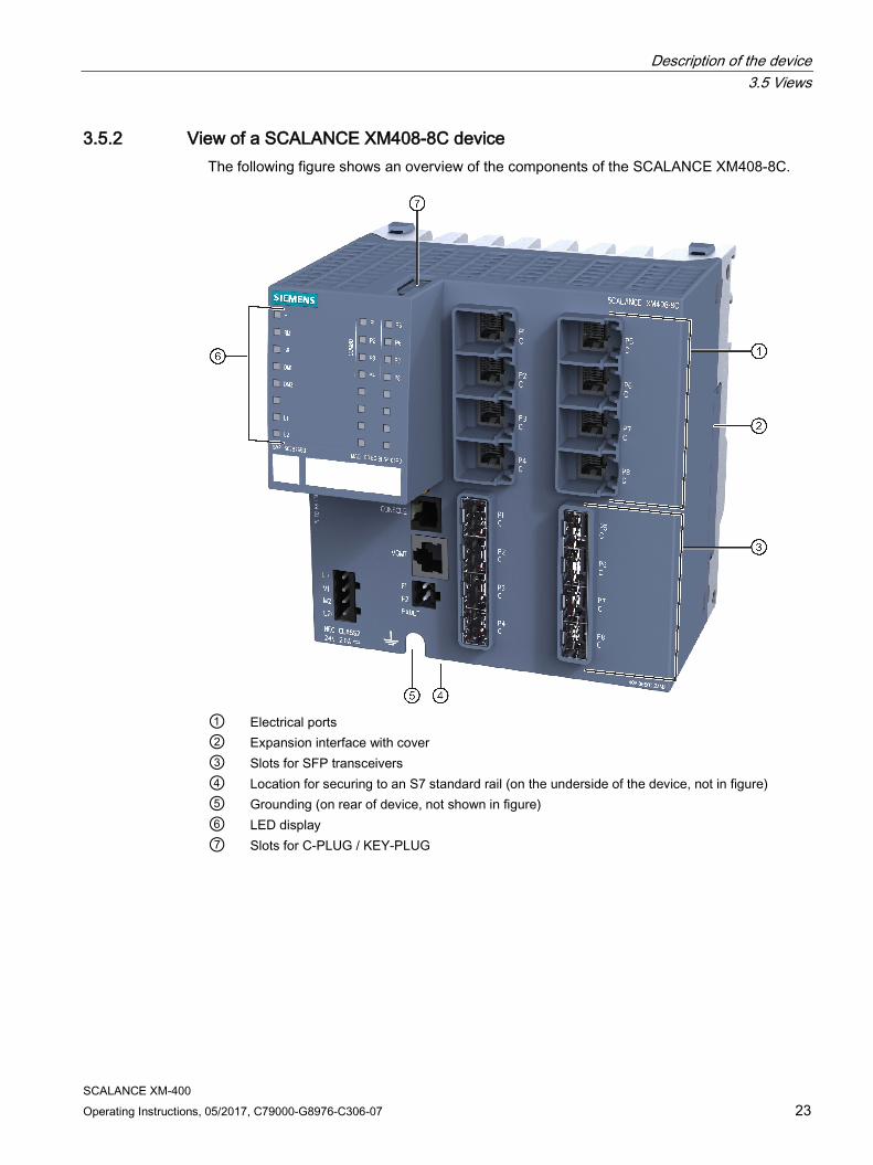
3.5.2 View of a SCALANCE XM408-8C device The following figure shows an overview of the components of the SCALANCE XM408-8C.
① Electrical ports ② Expansion interface with cover ③ Slots for SFP transceivers ④ Location for securing to an S7 standard rail (on the underside of the device, not in figure) ⑤ Grounding (on rear of device, not shown in figure) ⑥ LED display ⑦ Slots for C-PLUG / KEY-PLUG
Description of the device 3.5 Views
SCALANCE XM-400 24 Operating Instructions, 05/2017, C79000-G8976-C306-07
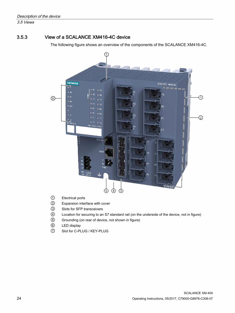
3.5.3 View of a SCALANCE XM416-4C device The following figure shows an overview of the components of the SCALANCE XM416-4C.
① Electrical ports ② Expansion interface with cover ③ Slots for SFP transceivers ④ Location for securing to an S7 standard rail (on the underside of the device, not in figure) ⑤ Grounding (on rear of device, not shown in figure) ⑥ LED display ⑦ Slot for C-PLUG / KEY-PLUG
Description of the device 3.6 SELECT / SET button
SCALANCE XM-400 Operating Instructions, 05/2017, C79000-G8976-C306-07 25
3.6 SELECT / SET button
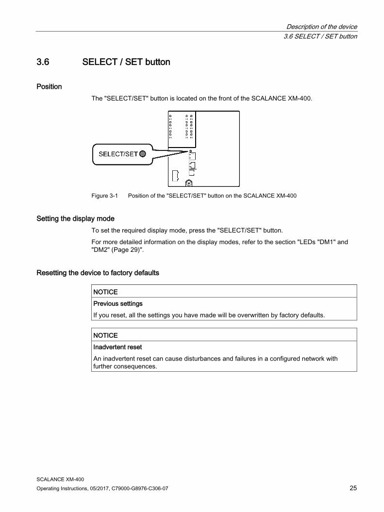
Position The "SELECT/SET" button is located on the front of the SCALANCE XM-400.
Figure 3-1 Position of the "SELECT/SET" button on the SCALANCE XM-400
Setting the display mode To set the required display mode, press the "SELECT/SET" button.
For more detailed information on the display modes, refer to the section "LEDs "DM1" and "DM2" (Page 29)".
Resetting the device to factory defaults
NOTICE
Previous settings
If you reset, all the settings you have made will be overwritten by factory defaults.
NOTICE
Inadvertent reset
An inadvertent reset can cause disturbances and failures in a configured network with further consequences.
Description of the device 3.6 SELECT / SET button
SCALANCE XM-400 26 Operating Instructions, 05/2017, C79000-G8976-C306-07
Requirement
● The device is in operation.
● The function "Restore Factory Defaults" is enabled for the "SELECT / SET" button.
Note
Reset despite disabled "SELECT/SET" button
If you have disabled the "Restore Factory Defaults" function for the "SELECT/SET" button in the configuration, this does not apply during the startup phase, see section "Restoring the factory settings (Page 62)".
If the function has been disabled in the configuration, it is only disabled on completion of the startup phase.
Procedure
To reset the device to the factory defaults during operation, follow the steps below:
1. Switch to display mode A.
Display mode A is active if the LEDS "DM1" and "DM2" are unlit.
If the "DM1" and "DM2" LEDs are lit or flashing, you will need to press the "SET/SELECT" repeatedly until the "DM1" and "DM2" LEDs go off.
If you do not press the "SELECT/SET" button for longer than 1 minute, the device automatically changes to display mode A.
2. Hold down the "SELECT/SET" button for 12 seconds.
After 9 seconds,the "DM1" and "DM2" LEDs start to flash for 3 seconds. At the same time, the port LEDs go on one after the other.
After you have held down the button for 12 seconds, the factory defaults are restored.
If you release the button before the 12 seconds have elapsed, the reset is canceled.
Enabling and disabling the button
In the configuration, you can enable or disable the button function.
Description of the device 3.6 SELECT / SET button
SCALANCE XM-400 Operating Instructions, 05/2017, C79000-G8976-C306-07 27
Defining the fault mask Using the fault mask, you specify an individual "good status" for the connected ports and the power supply. Deviations from this status are displayed as errors/faults.
To define the fault mask, follow the steps below:
1. Switch to display mode D.
Display mode D is active if the "DM1" and "DM2" LEDs are lit green..
If another display mode is active, you will need to press the "SET/SELECT" button repeatedly until the "DM1" and "DM2" LEDs are lit green.
2. Hold down the "SELECT/SET" button for 5 seconds.
After 2 seconds,the "DM1" and "DM2" LEDs start to flash for 3 seconds. At the same time, the port LEDs go on one after the other.
After you have held down the button for 5 seconds, the current settings are stored as the "good status".
If you release the button before the 5 seconds have elapsed, the previous fault mask will be retained.
Enabling/disabling the redundancy manager To enable/disable the redundancy manager, follow the steps below:
1. Switch to display mode B.
Display mode B is active if the "DM1" LED is lit green and the "DM2" LED is off..
If another display mode is active, you will need to press the "SET/SELECT" button repeatedly until the "DM1" LED is lit green and the "DM2" LED is off.
2. Hold down the "SELECT/SET" button for 5 seconds.
After 2 seconds,the "DM1", "DM2" and "RM" LEDs start to flash for 3 seconds. At the same time, the port LEDs go on one after the other.
If you release the button before the 5 seconds have elapsed, the action is canceled.
The result of the action depends on the initial situation:
– Initial situation: The redundancy manager and media redundancy are disabled. Result: After enabling the redundancy manager, media redundancy is also enabled.
– Initial situation: The redundancy manager and media redundancy are enabled. Result: After disabling the redundancy manager, media redundancy remains enabled.
Description of the device 3.7 LED display
SCALANCE XM-400 28 Operating Instructions, 05/2017, C79000-G8976-C306-07
3.7 LED display
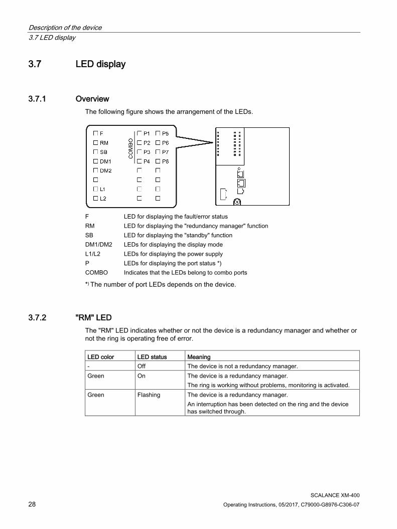
3.7.1 Overview The following figure shows the arrangement of the LEDs.
F LED for displaying the fault/error status RM LED for displaying the "redundancy manager" function SB LED for displaying the "standby" function DM1/DM2 LEDs for displaying the display mode L1/L2 LEDs for displaying the power supply P LEDs for displaying the port status *) COMBO Indicates that the LEDs belong to combo ports
*) The number of port LEDs depends on the device.
3.7.2 "RM" LED The "RM" LED indicates whether or not the device is a redundancy manager and whether or not the ring is operating free of error. LED color LED status Meaning - Off The device is not a redundancy manager. Green On The device is a redundancy manager.
The ring is working without problems, monitoring is activated. Green Flashing The device is a redundancy manager.
An interruption has been detected on the ring and the device has switched through.
Description of the device 3.7 LED display
SCALANCE XM-400 Operating Instructions, 05/2017, C79000-G8976-C306-07 29
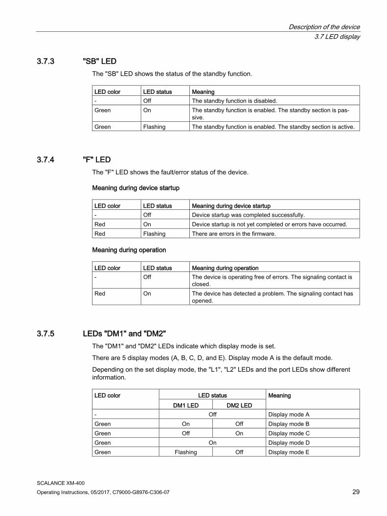
3.7.3 "SB" LED The "SB" LED shows the status of the standby function. LED color LED status Meaning - Off The standby function is disabled. Green On The standby function is enabled. The standby section is pas-
sive. Green Flashing The standby function is enabled. The standby section is active.
3.7.4 "F" LED The "F" LED shows the fault/error status of the device.
Meaning during device startup LED color LED status Meaning during device startup - Off Device startup was completed successfully. Red On Device startup is not yet completed or errors have occurred. Red Flashing There are errors in the firmware.
Meaning during operation LED color LED status Meaning during operation - Off The device is operating free of errors. The signaling contact is
closed. Red On The device has detected a problem. The signaling contact has
opened.
3.7.5 LEDs "DM1" and "DM2" The "DM1" and "DM2" LEDs indicate which display mode is set.
There are 5 display modes (A, B, C, D, and E). Display mode A is the default mode.
Depending on the set display mode, the "L1", "L2" LEDs and the port LEDs show different information. LED color LED status Meaning
DM1 LED DM2 LED - Off Display mode A Green On Off Display mode B Green Off On Display mode C Green On Display mode D Green Flashing Off Display mode E
Description of the device 3.7 LED display
SCALANCE XM-400 30 Operating Instructions, 05/2017, C79000-G8976-C306-07
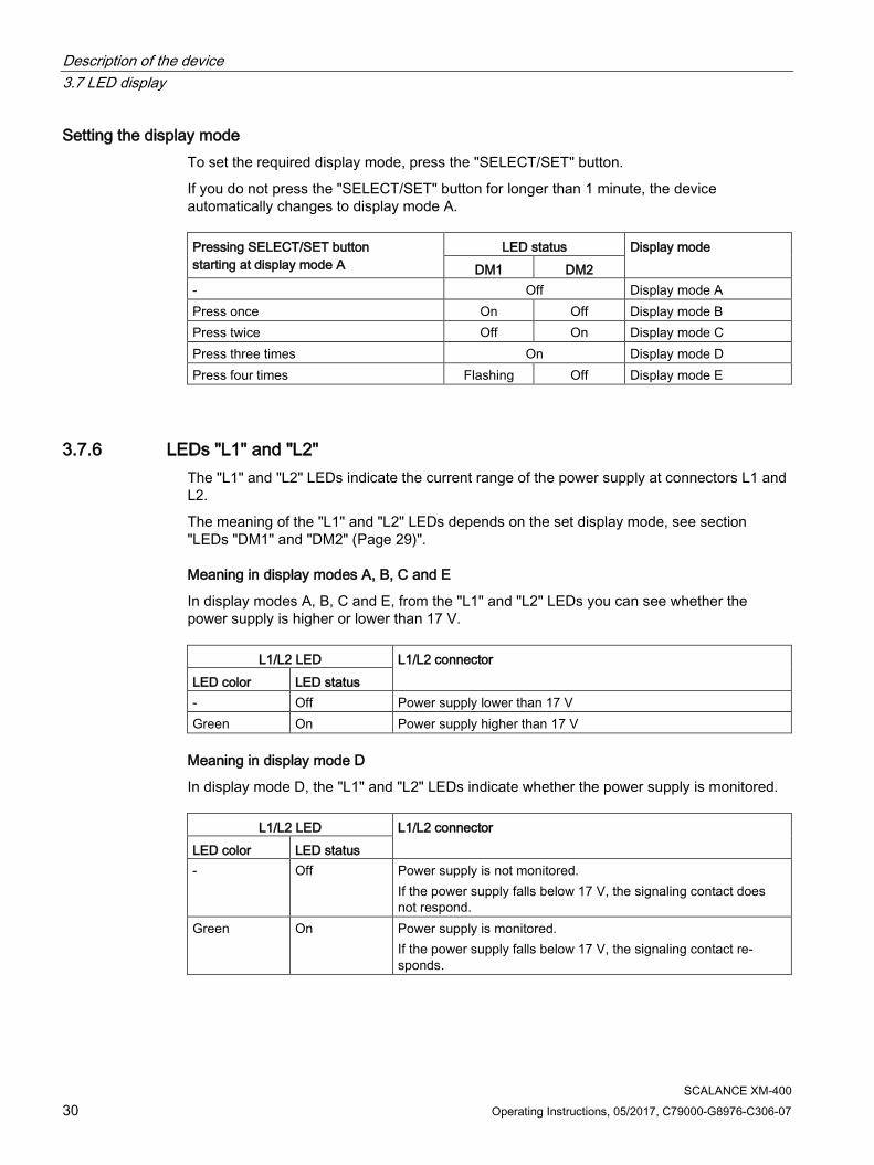
Setting the display mode To set the required display mode, press the "SELECT/SET" button.
If you do not press the "SELECT/SET" button for longer than 1 minute, the device automatically changes to display mode A. Pressing SELECT/SET button starting at display mode A
LED status Display mode DM1 DM2
- Off Display mode A Press once On Off Display mode B Press twice Off On Display mode C Press three times On Display mode D Press four times Flashing Off Display mode E
3.7.6 LEDs "L1" and "L2" The "L1" and "L2" LEDs indicate the current range of the power supply at connectors L1 and L2.
The meaning of the "L1" and "L2" LEDs depends on the set display mode, see section "LEDs "DM1" and "DM2" (Page 29)".
Meaning in display modes A, B, C and E
In display modes A, B, C and E, from the "L1" and "L2" LEDs you can see whether the power supply is higher or lower than 17 V.
L1/L2 LED L1/L2 connector LED color LED status
- Off Power supply lower than 17 V Green On Power supply higher than 17 V
Meaning in display mode D
In display mode D, the "L1" and "L2" LEDs indicate whether the power supply is monitored.
L1/L2 LED L1/L2 connector LED color LED status
- Off Power supply is not monitored. If the power supply falls below 17 V, the signaling contact does not respond.
Green On Power supply is monitored. If the power supply falls below 17 V, the signaling contact re-sponds.
Description of the device 3.7 LED display
SCALANCE XM-400 Operating Instructions, 05/2017, C79000-G8976-C306-07 31
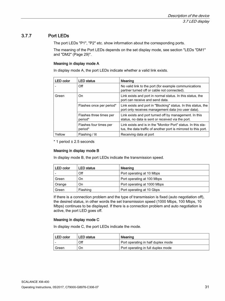
3.7.7 Port LEDs The port LEDs "P1", "P2" etc. show information about the corresponding ports.
The meaning of the Port LEDs depends on the set display mode, see section "LEDs "DM1" and "DM2" (Page 29)".
Meaning in display mode A
In display mode A, the port LEDs indicate whether a valid link exists. LED color LED status Meaning - Off No valid link to the port (for example communications
partner turned off or cable not connected). Green On Link exists and port in normal status. In this status, the
port can receive and send data. Flashes once per period* Link exists and port in "Blocking" status. In this status, the
port only receives management data (no user data). Flashes three times per period*
Link exists and port turned off by management. In this status, no data is sent or received via the port.
Flashes four times per period*
Link exists and is in the "Monitor Port" status. In this sta-tus, the data traffic of another port is mirrored to this port.
Yellow Flashing / lit Receiving data at port
* 1 period ≙ 2.5 seconds
Meaning in display mode B
In display mode B, the port LEDs indicate the transmission speed. LED color LED status Meaning - Off Port operating at 10 Mbps Green On Port operating at 100 Mbps Orange On Port operating at 1000 Mbps Green Flashing Port operating at 10 Gbps
If there is a connection problem and the type of transmission is fixed (auto negotiation off), the desired status, in other words the set transmission speed (1000 Mbps, 100 Mbps, 10 Mbps) continues to be displayed. If there is a connection problem and auto negotiation is active, the port LED goes off.
Meaning in display mode C
In display mode C, the port LEDs indicate the mode. LED color LED status Meaning - Off Port operating in half duplex mode Green On Port operating in full duplex mode
Description of the device 3.7 LED display
SCALANCE XM-400 32 Operating Instructions, 05/2017, C79000-G8976-C306-07
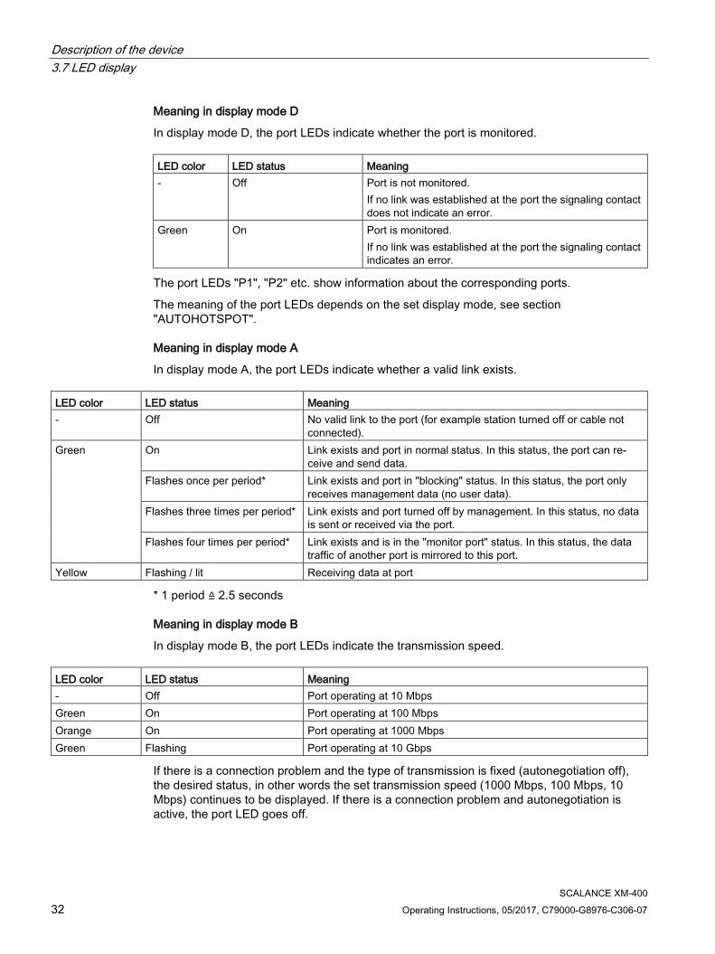
Meaning in display mode D
In display mode D, the port LEDs indicate whether the port is monitored. LED color LED status Meaning - Off Port is not monitored.
If no link was established at the port the signaling contact does not indicate an error.
Green On Port is monitored. If no link was established at the port the signaling contact indicates an error.
The port LEDs "P1", "P2" etc. show information about the corresponding ports.
The meaning of the port LEDs depends on the set display mode, see section "AUTOHOTSPOT".
Meaning in display mode A
In display mode A, the port LEDs indicate whether a valid link exists. LED color LED status Meaning - Off No valid link to the port (for example station turned off or cable not
connected). Green On Link exists and port in normal status. In this status, the port can re-
ceive and send data. Flashes once per period* Link exists and port in "blocking" status. In this status, the port only
receives management data (no user data). Flashes three times per period* Link exists and port turned off by management. In this status, no data
is sent or received via the port. Flashes four times per period* Link exists and is in the "monitor port" status. In this status, the data
traffic of another port is mirrored to this port. Yellow Flashing / lit Receiving data at port
* 1 period ≙ 2.5 seconds
Meaning in display mode B
In display mode B, the port LEDs indicate the transmission speed. LED color LED status Meaning - Off Port operating at 10 Mbps Green On Port operating at 100 Mbps Orange On Port operating at 1000 Mbps Green Flashing Port operating at 10 Gbps
If there is a connection problem and the type of transmission is fixed (autonegotiation off), the desired status, in other words the set transmission speed (1000 Mbps, 100 Mbps, 10 Mbps) continues to be displayed. If there is a connection problem and autonegotiation is active, the port LED goes off.
Description of the device 3.7 LED display
SCALANCE XM-400 Operating Instructions, 05/2017, C79000-G8976-C306-07 33
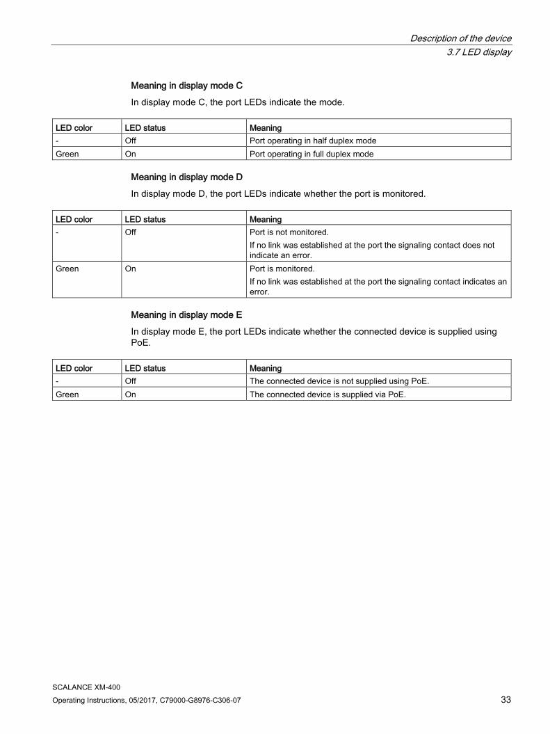
Meaning in display mode C
In display mode C, the port LEDs indicate the mode. LED color LED status Meaning - Off Port operating in half duplex mode Green On Port operating in full duplex mode
Meaning in display mode D
In display mode D, the port LEDs indicate whether the port is monitored. LED color LED status Meaning - Off Port is not monitored.
If no link was established at the port the signaling contact does not indicate an error.
Green On Port is monitored. If no link was established at the port the signaling contact indicates an error.
Meaning in display mode E
In display mode E, the port LEDs indicate whether the connected device is supplied using PoE.
LED color LED status Meaning - Off The connected device is not supplied using PoE. Green On The connected device is supplied via PoE.
Description of the device 3.8 C-PLUG/KEY-PLUG
SCALANCE XM-400 34 Operating Instructions, 05/2017, C79000-G8976-C306-07
3.8 C-PLUG/KEY-PLUG
3.8.1 Function of the C-PLUG/KEY-PLUG
NOTICE
Do not remove or insert a C-PLUG/KEY-PLUG during operation
A C-PLUG/KEY-PLUG may only be removed or inserted when the device is turned off.
Saving configuration data and enabling layer 3 functionality A PLUG is an exchangeable storage medium for storing the configuration data of the device. This allows fast and uncomplicated replacement of a device. The PLUG is taken from the previous device and inserted in the new device. The first time it is started up, the replacement device has the same configuration as the previous device except for the device-specific MAC address set by the vendor.
A C-PLUG stores the current information about the configuration of a device.
In addition to the configuration, a KEY-PLUG also contains a license with which layer 3 functionality is enabled.
Note
The device can also be operated without a C-PLUG/KEY-PLUG.
How it works
Operating mode
In terms of the C-PLUG / KEY-PLUG, there are three modes for the device:
● Without C-PLUG/KEY-PLUG
The device stores the configuration in internal memory. This mode is active if no C-PLUG/KEY-PLUG is inserted.
● With unwritten C-PLUG/KEY-PLUG
If an unwritten C-PLUG/KEY-PLUG (factory status or deleted with Clean function) is used, the local configuration already existing on the device is automatically stored on the inserted C-PLUG/KEY-PLUG during startup. This mode is active as soon as an unwritten C-PLUG/KEY-PLUG is inserted.
● With written C-PLUG/KEY-PLUG
A device with a written and accepted C-PLUG/KEY-PLUG ("ACCEPTED" status) automatically uses its configuration data during startup. Acceptance is only possible if the data was written by a compatible device type. This mode is active as soon as a written C-PLUG/KEY-PLUG is inserted.
Description of the device 3.8 C-PLUG/KEY-PLUG
SCALANCE XM-400 Operating Instructions, 05/2017, C79000-G8976-C306-07 35
Operation with C-PLUG/KEY-PLUG
The configuration stored on the C-PLUG/KEY-PLUG is displayed via the user interfaces.
If changes are made to the configuration, the device stores the configuration directly on the C-PLUG/KEY-PLUG, if this is in the "ACCEPTED" status. The internal memory is neither read nor written.
Response to errors Inserting a C-PLUG/KEY-PLUG that does not contain the configuration of a compatible device type, accidentally removing the C-PLUG/KEY-PLUG or general malfunctions of the C-PLUG/KEY-PLUG are signaled by the diagnostics mechanisms of the device (LEDs, Web-based management (WBM), SNMP, Command Line Interface (CLI) and PROFINET diagnostics).
The user then has the choice of either removing the C-PLUG/KEY-PLUG again or selecting the option to reformat the C-PLUG/KEY-PLUG.
3.8.2 Replacing the C-PLUG/KEY-PLUG
Position of the C-PLUG/KEY-PLUG
NOTICE
Do not remove or insert a C-PLUG/KEY-PLUG during operation
A C-PLUG/KEY-PLUG may only be removed or inserted when the device is turned off.
The device checks whether or not a C-PLUG/KEY-PLUG is inserted at one second intervals. If it is detected that the C-PLUG/KEY-PLUG was removed, there is a restart.
If a KEY-PLUG was inserted in the device, the device changes to a defined error state following the restart.
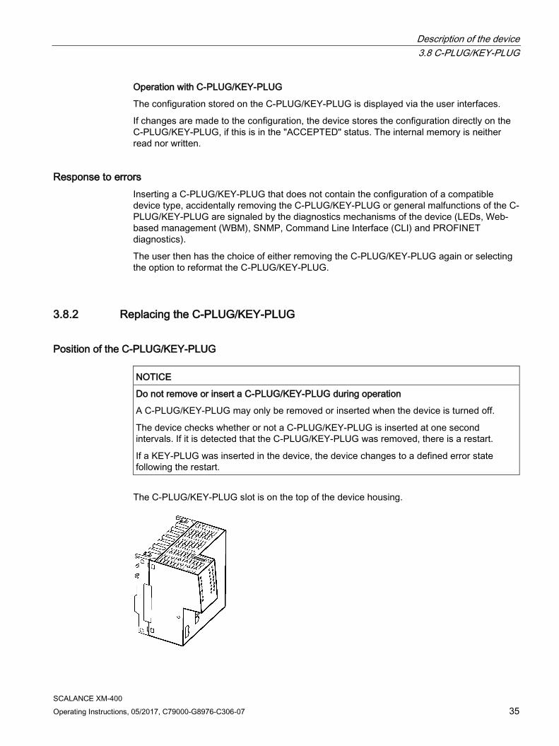
The C-PLUG/KEY-PLUG slot is on the top of the device housing.
Description of the device 3.8 C-PLUG/KEY-PLUG
SCALANCE XM-400 36 Operating Instructions, 05/2017, C79000-G8976-C306-07
Replacing a C-PLUG/KEY-PLUG
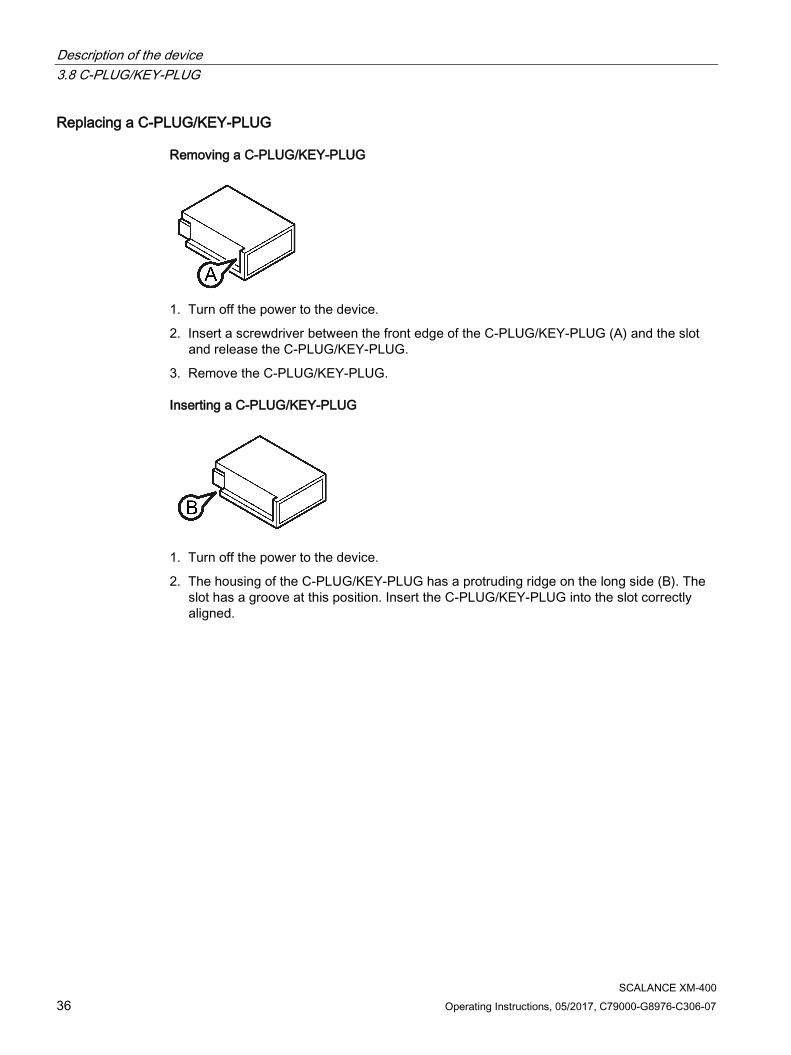
Removing a C-PLUG/KEY-PLUG
1. Turn off the power to the device.
2. Insert a screwdriver between the front edge of the C-PLUG/KEY-PLUG (A) and the slot and release the C-PLUG/KEY-PLUG.
3. Remove the C-PLUG/KEY-PLUG.
Inserting a C-PLUG/KEY-PLUG
1. Turn off the power to the device.
2. The housing of the C-PLUG/KEY-PLUG has a protruding ridge on the long side (B). The slot has a groove at this position. Insert the C-PLUG/KEY-PLUG into the slot correctly aligned.
Description of the device 3.9 Functions
SCALANCE XM-400 Operating Instructions, 05/2017, C79000-G8976-C306-07 37
3.9 Functions
3.9.1 Combo ports
Characteristics Combo port is the name for two communication ports. A combo port has the two following jacks:
● a fixed RJ-45 port
● an SFP transceiver slot that can be equipped individually
Of these two ports, only one can ever be active. Using the mode, you can decide how the ports are prioritized.
The port name is the same on both jacks of the combo port, for example "PxC".
There is an LED for each combo port. The LEDs for the combo ports can be identified by a vertical line and the word "COMBO". The labeling of the combo port LEDs does not differ from that of the other LEDs, e.g. "P3".
Setting the mode The following modes can be configured for a combo port:
● Mode 1: auto
The SFP transceiver port has priority. As soon as an SFP transceiver is plugged in, an existing connection at the fixed RJ-45 port is terminated. If no SFC transceiver is plugged in, a connection can be established via the fixed RJ-45 port.
● Mode 2: rj45
The fixed RJ-45 port is independent of the SFP transceiver port.
● Mode 3: sfp
The pluggable transceiver port is used independent of the fixed RJ-45 port.
The factory setting for the combo ports is mode 1: auto
You configure the mode with Web Based Management or the Command Line Interface.
Description of the device 3.9 Functions
SCALANCE XM-400 38 Operating Instructions, 05/2017, C79000-G8976-C306-07
3.9.2 Power over Ethernet (PoE)
Function The "Power over Ethernet" function supplies connected devices with power via the Ethernet cable. Devices supplied with power via an Ethernet cable do not require a separate voltage source.
PoE-compliant devices can be divided into the following groups:
● Power source (PSE - Power Sourcing Equipment)
These inject power onto the Ethernet cable.
● Power consumer (PD - Powered Device)
These are supplied with power via the Ethernet cable.
Power over Ethernet with SCALANCE XM-400 With a SCALANCE XM-400, you can use the "Power over Ethernet" function via the port extender PE408PoE as the power generator.
You will find suitable PoE power supplies in the section "Accessories (Page 18)".
You will find detailed information on the port extender PE408PoE in the operating instructions "Extenders for SCALANCE XM-400".
You will find the Operating Instructions here:
● On the data medium that ships with some products:
– Product CD / product DVD
– SIMATIC NET Manual Collection
● On the Internet pages of Siemens Industry Online Support (http://support.automation.siemens.com/WW/view/en/79730528/133300)
Description of the device 3.9 Functions
SCALANCE XM-400 Operating Instructions, 05/2017, C79000-G8976-C306-07 39
3.9.3 Near Field Communication
Information on Near Field Communication ● Near Field Communication (NFC) is a wireless communications technique.
● With a mobile end device that supports NFC Forum Type 4 Tags, you can read out information via the SCALANCE XM-400.
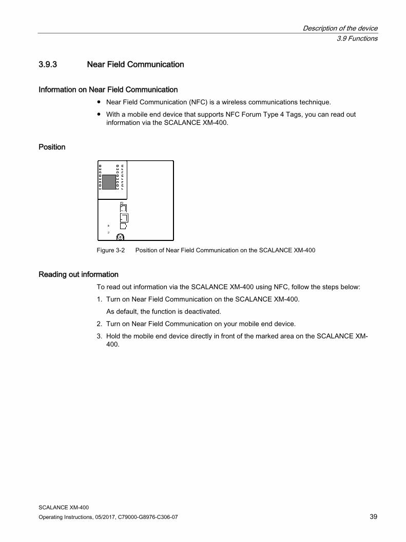
Position
Figure 3-2 Position of Near Field Communication on the SCALANCE XM-400
Reading out information To read out information via the SCALANCE XM-400 using NFC, follow the steps below:
1. Turn on Near Field Communication on the SCALANCE XM-400.
As default, the function is deactivated.
2. Turn on Near Field Communication on your mobile end device.
3. Hold the mobile end device directly in front of the marked area on the SCALANCE XM-400.

Description of the device 3.9 Functions
SCALANCE XM-400 40 Operating Instructions, 05/2017, C79000-G8976-C306-07
SCALANCE XM-400 Operating Instructions, 05/2017, C79000-G8976-C306-07 41
Installation 4 4.1 Safety notices for installation
Safety notices When installing the device, keep to the safety notices listed below.
WARNING
If a device is operated in an ambient temperature of more than 50 °C, the temperature of the device housing may be higher than 70 °C. The device must therefore be installed so that it is only accessible to service personnel or users that are aware of the reason for restricted access and the required safety measures at an ambient temperature higher than 50 °C.
Safety notices on use in hazardous areas
General safety notices relating to protection against explosion
WARNING
EXPLOSION HAZARD
Replacing components may impair suitability for Class 1, Division 2 or Zone 2.
WARNING
The device may only be operated in an environment with pollution degree 1 or 2 (see IEC 60664-1).
WARNING
When used in hazardous environments corresponding to Class I, Division 2 or Class I, Zone 2, the device must be installed in a cabinet or a suitable enclosure.
Installation 4.1 Safety notices for installation
SCALANCE XM-400 42 Operating Instructions, 05/2017, C79000-G8976-C306-07
Safety notices for use according to ATEX and IECEx
If you use the device under ATEX or IECEx conditions you must also keep to the following safety notices in addition to the general safety notices for protection against explosion:
WARNING
To comply with EC Directive 2014/34/EU (ATEX 114) or the conditions of IECEx, this enclosure or cabinet must meet the requirements of at least IP54 in compliance with EN 60529.
WARNING
If the cable or conduit entry point exceeds 70 °C or the branching point of conductors exceeds 80 °C, special precautions must be taken. If the equipment is operated in an air ambient in excess of 60 ℃, only use cables with admitted maximum operating temperature of at least 80 ℃.
Further notes
CAUTION
Use only approved components
If you use components and accessories that are not approved for SIMATIC NET devices or their target systems, this may violate the requirements and regulations for safety and electromagnetic compatibility. Only use components approved for the SIMATIC NET devices.
NOTICE
Warming and premature aging of the IE switch due to direct sunlight
Direct sunlight can heat up the device and can lead to premature aging of the IE switch and its cabling.
Provide suitable shade to protect the IE switch against direct sunlight.
Note
During installation and operation, keep to the installation guidelines and safety notices described in this document and in the system manuals "Industrial Ethernet / PROFINET Industrial Ethernet" and "Industrial Ethernet / PROFINET passive network components".
You will find information on the system manuals in the section "AUTOHOTSPOT", in "Further documentation".
Installation 4.2 Types of installation
SCALANCE XM-400 Operating Instructions, 05/2017, C79000-G8976-C306-07 43
4.2 Types of installation
Types of installation You have the following options for the device:
● DIN rail
● S7-300 standard rail
● S7-1500 standard rail
4.3 Mounting on DIN rails
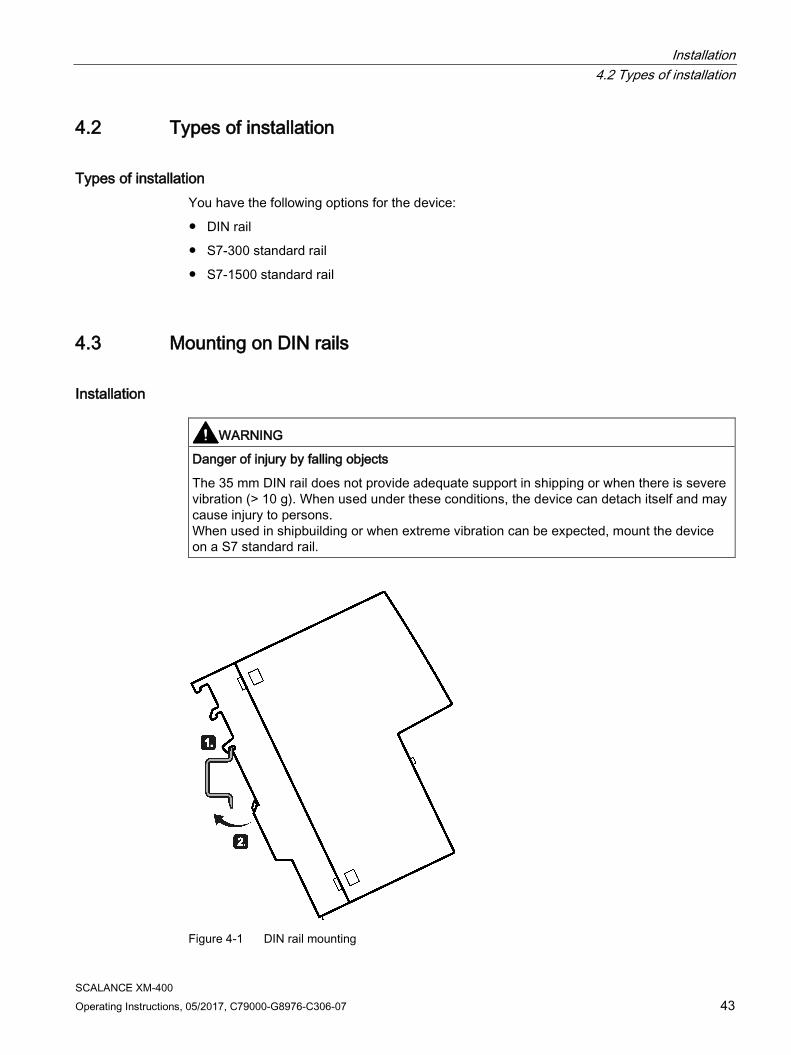
Installation
WARNING
Danger of injury by falling objects
The 35 mm DIN rail does not provide adequate support in shipping or when there is severe vibration (> 10 g). When used under these conditions, the device can detach itself and may cause injury to persons. When used in shipbuilding or when extreme vibration can be expected, mount the device on a S7 standard rail.
Figure 4-1 DIN rail mounting
Installation 4.4 Installation on a standard S7-300 rail
SCALANCE XM-400 44 Operating Instructions, 05/2017, C79000-G8976-C306-07
To install the device on a 35 mm DIN rail complying with DIN EN 60715, follow the steps below:
1. Place the third housing guide of the device on the top edge of the DIN rail ①.
2. Press the device down against the DIN rail until the spring catch locks in place ②.
3. Fit the connectors for the power supply, see the section "Power supply (Page 54)".
4. Fit the connectors for the signaling contact, see the section "Signaling contact (Page 55)".
5. Insert the terminal blocks into the sockets on the device.
Removal To remove the device from a DIN rail, follow the steps below:
1. Disconnect all connected cables.
2. Release the DIN rail catch on the bottom of the device using a screwdriver.
3. Pull lower part of the device away from the DIN rail.
4.4 Installation on a standard S7-300 rail
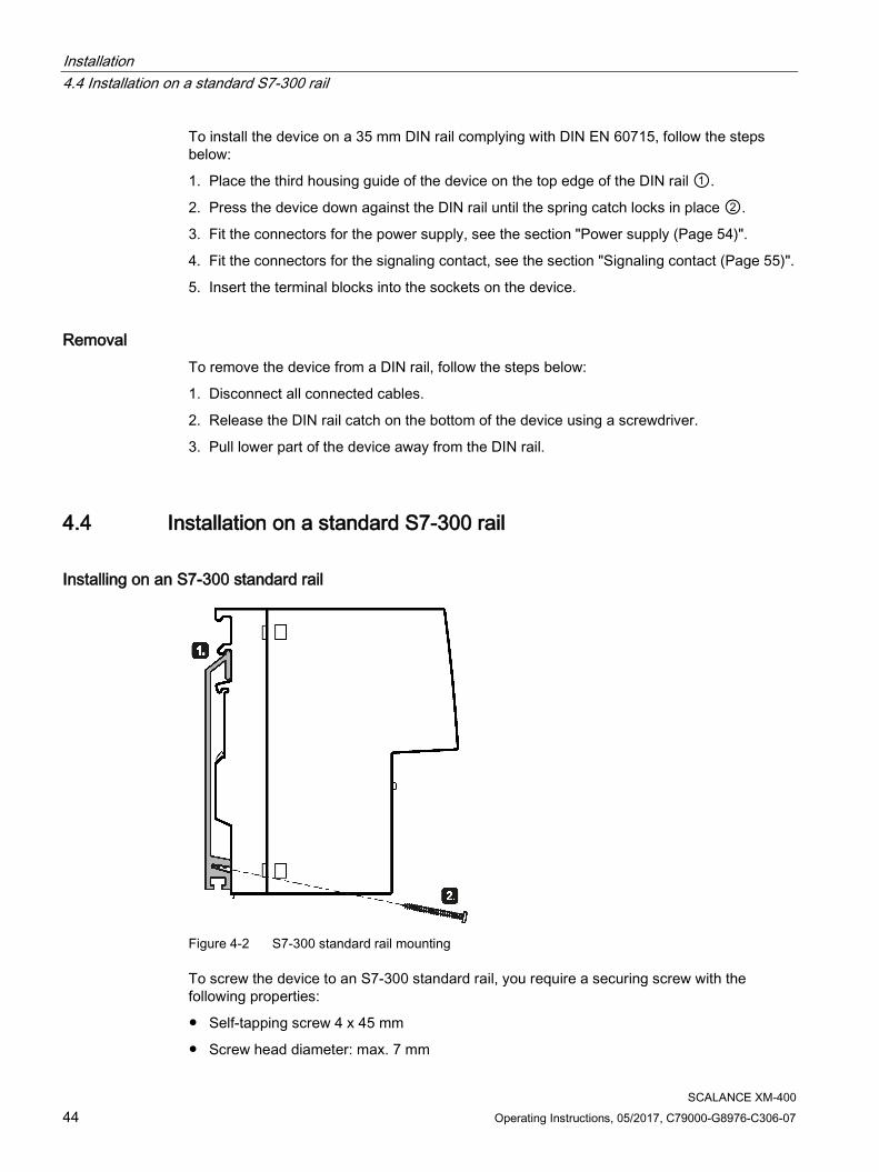
Installing on an S7-300 standard rail
Figure 4-2 S7-300 standard rail mounting
To screw the device to an S7-300 standard rail, you require a securing screw with the following properties:
● Self-tapping screw 4 x 45 mm
● Screw head diameter: max. 7 mm

Installation 4.5 Installation on a standard S7-1500 rail
SCALANCE XM-400 Operating Instructions, 05/2017, C79000-G8976-C306-07 45
To install the device on an S7-300 standard rail, follow the steps below:
1. Place the second housing guide of the device on the top edge of the standard rail ①.
2. Screw the device to the lower part of the standard rail with the supplied securing screw ② (tightening torque 1.5 Nm), see also "Views (Page 22)".
3. Fit the connectors for the power supply, refer to the section "Power supply (Page 54)".
4. Fit the connectors for the signaling contact, refer to the section "Signaling contact (Page 55)".
5. Insert the terminal blocks into the sockets on the device.
Removal To remove the device from a standard rail, follow the steps below:
1. Disconnect all connected cables.
2. Release the screw on the underside of the standard rail.
3. Remove the device from the standard rail.
4.5 Installation on a standard S7-1500 rail
Installing on an S7-1500 standard rail
Figure 4-3 S7-1500 standard rail mounting
Installation 4.6 Fitting an extender
SCALANCE XM-400 46 Operating Instructions, 05/2017, C79000-G8976-C306-07
To screw the device to an S7-1500 standard rail, you require a securing screw with the following properties:
● Self-tapping screw 4 x 45 mm
● Screw head diameter: max. 7 mm
To install the device on an S7-1500 standard rail, follow the steps below:
1. Place the first housing guide of the device on the top edge of the standard rail ①.
2. Screw the device to the lower part of the standard rail with the supplied securing screw ② (tightening torque 1.5 Nm), see also "Views (Page 22)".
3. Fit the connectors for the power supply, refer to the section "Power supply (Page 54)".
4. Fit the connectors for the signaling contact, refer to the section "Signaling contact (Page 55)".
5. Insert the terminal blocks into the sockets on the device.
Removal To remove the device from a standard rail, follow the steps below:
1. Disconnect all connected cables.
2. Release the screw on the underside of the standard rail.
3. Remove the device from the standard rail.
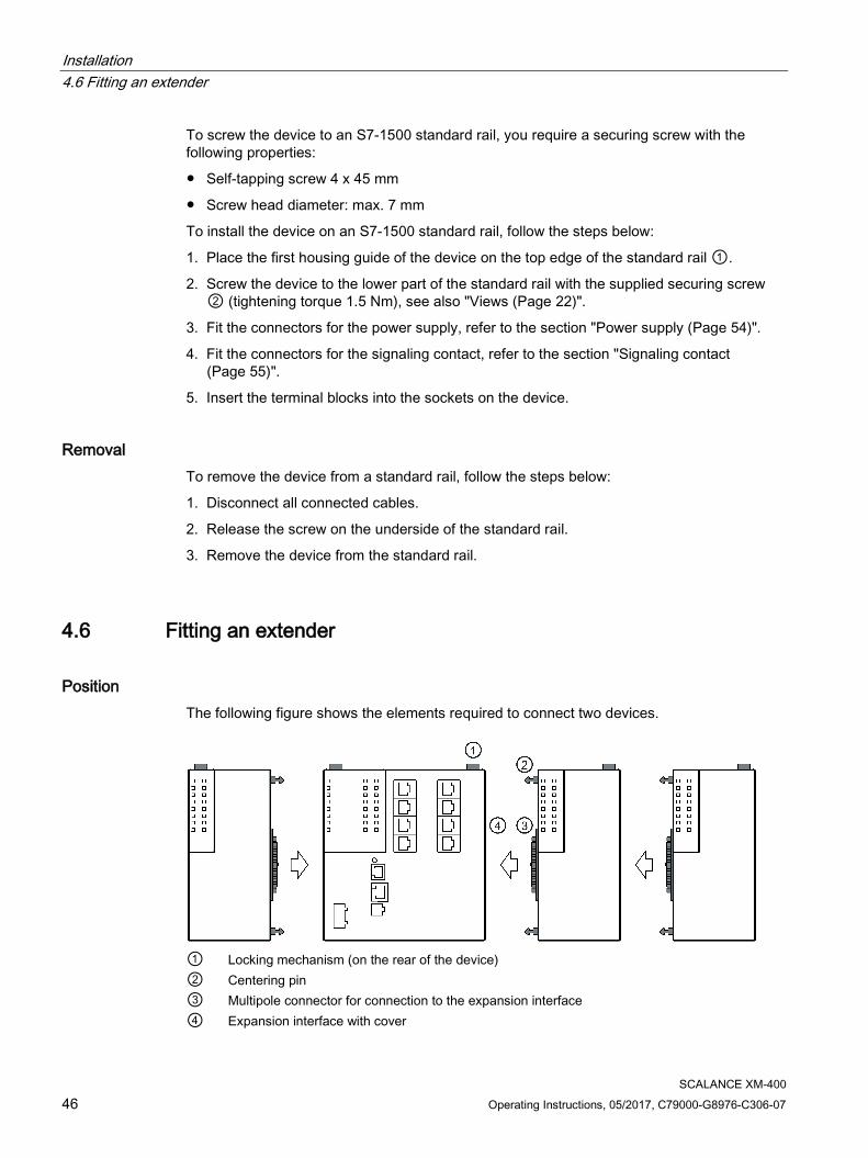
4.6 Fitting an extender
Position The following figure shows the elements required to connect two devices.
① Locking mechanism (on the rear of the device) ② Centering pin ③ Multipole connector for connection to the expansion interface ④ Expansion interface with cover
Installation 4.6 Fitting an extender
SCALANCE XM-400 Operating Instructions, 05/2017, C79000-G8976-C306-07 47
Via the expansion interface, the basic device supplies the extenders with power and manages the ports of the extenders.
The power provided by the PE408PoE port extender for Power over Ethernet does not come from the basic device. Connect an external power source, see e.g. section "Accessories (Page 18)".
Types of installation You have the following options when connecting devices:
● You can connect the devices and mount them together on a DIN or S7 standard rail.
● You can mount a device on a DIN or S7 standard rail and expand it later.
Note
For mounting on a rail as well as for removing from the rail, plan enough space between the devices, see section "Extender dimension drawings (Page 71)".
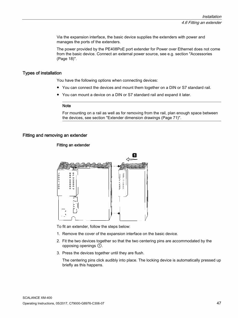
Fitting and removing an extender
Fitting an extender
To fit an extender, follow the steps below:
1. Remove the cover of the expansion interface on the basic device.
2. Fit the two devices together so that the two centering pins are accommodated by the opposing openings ①.
3. Press the devices together until they are flush.
The centering pins click audibly into place. The locking device is automatically pressed up briefly as this happens.
Installation 4.6 Fitting an extender
SCALANCE XM-400 48 Operating Instructions, 05/2017, C79000-G8976-C306-07
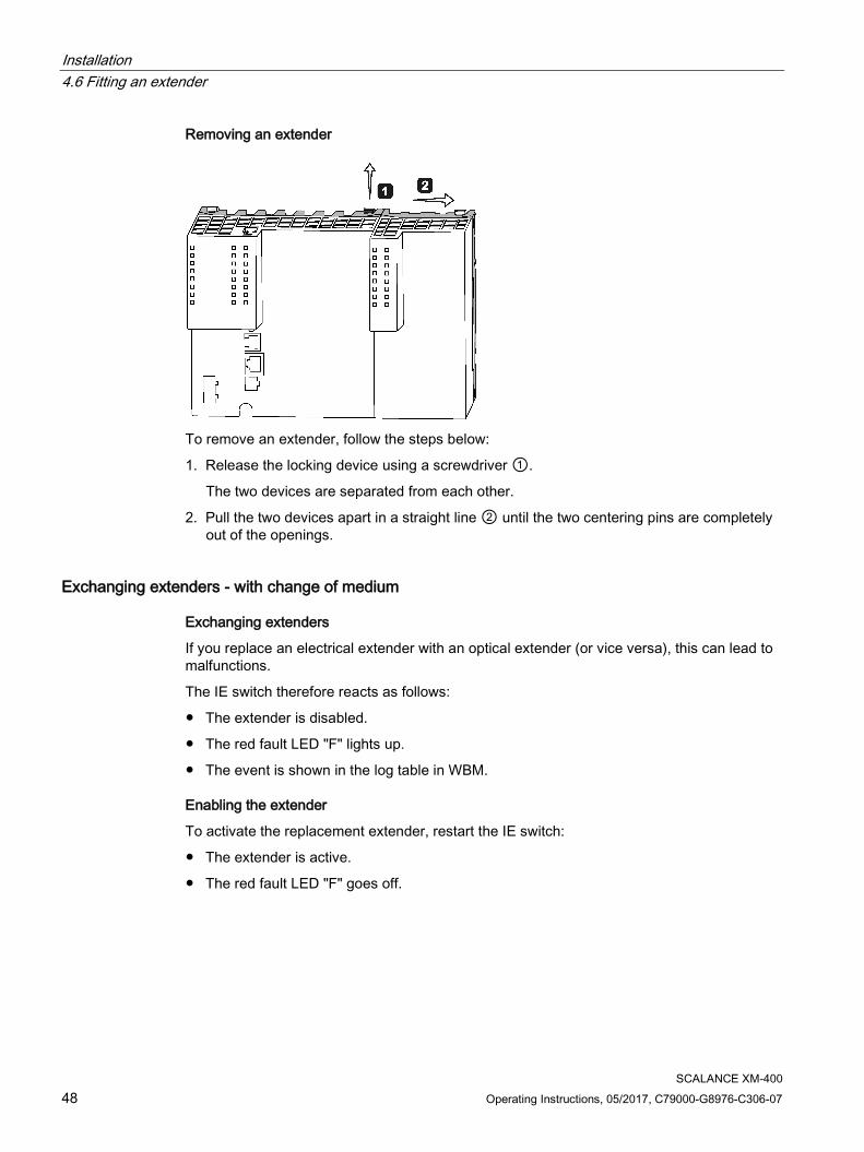
Removing an extender
To remove an extender, follow the steps below:
1. Release the locking device using a screwdriver ①.
The two devices are separated from each other.
2. Pull the two devices apart in a straight line ② until the two centering pins are completely out of the openings.
Exchanging extenders - with change of medium
Exchanging extenders
If you replace an electrical extender with an optical extender (or vice versa), this can lead to malfunctions.
The IE switch therefore reacts as follows:
● The extender is disabled.
● The red fault LED "F" lights up.
● The event is shown in the log table in WBM.
Enabling the extender
To activate the replacement extender, restart the IE switch:
● The extender is active.
● The red fault LED "F" goes off.
Installation 4.7 General notes for SFP transceivers
SCALANCE XM-400 Operating Instructions, 05/2017, C79000-G8976-C306-07 49
4.7 General notes for SFP transceivers
WARNING
Use only approved SFP transceivers
If you use SFP transceivers that have not been approved by Siemens AG, there is no guarantee that the device will function according to its specifications. If you use unapproved SFP transceivers, this can lead to the following problems: • Damage to the device • Loss of the approvals • Violation of the EMC regulations
Use only approved pluggable transceivers.
Note Plugging and pulling during operation
You can plug and pull pluggable transceivers with the device in operation.
Documentation for SFP transceivers You will find detailed information in the operating instructions of the pluggable transceivers, see the chapter "Introduction (Page 5)" section "Additional documentation".

Installation 4.7 General notes for SFP transceivers
SCALANCE XM-400 50 Operating Instructions, 05/2017, C79000-G8976-C306-07

SCALANCE XM-400 Operating Instructions, 05/2017, C79000-G8976-C306-07 51
Connecting up 5 5.1 Safety when connecting up
Safety notices When connecting up the device, keep to the safety notices listed below.
WARNING
The equipment is designed for operation with Safety Extra-Low Voltage (SELV) by a Limited Power Source (LPS).
This means that only SELV / LPS complying with IEC 60950-1 / EN 60950-1 / VDE 0805-1 must be connected to the power supply terminals, or the power supply unit for the equipment power supply must comply with NEC Class 2, as described by the National Electrical Code (r) (ANSI / NFPA 70).
If the equipment is connected to a redundant power supply (two separate power supplies), both must meet these requirements.
NOTICE
Failure of the data traffic due to contamination of optical plug-in connections
Optical sockets and plugs are sensitive to contamination of the end face. Contamination can lead to the failure of the optical transmission network.
Close unused optical sockets and plugs as well as pluggable transceivers and slots with the supplied protective caps.
Remove the protective caps only immediately before you use the plug-in connection.
Safety notices on use in hazardous areas
General safety notices relating to protection against explosion
WARNING
EXPLOSION HAZARD
Do not connect or disconnect cables to or from the device when a flammable or combustible atmosphere is present.

Connecting up 5.1 Safety when connecting up
SCALANCE XM-400 52 Operating Instructions, 05/2017, C79000-G8976-C306-07
Safety notices when using the device according to Hazardous Locations (HazLoc)
If you use the device under HazLoc conditions you must also keep to the following safety notices in addition to the general safety notices for protection against explosion:
WARNING
EXPLOSION HAZARD
You may only connect or disconnect cables carrying electricity when the power supply is switched off or when the device is in an area without inflammable gas concentrations.
Safety notices for use according to ATEX and IECEx
If you use the device under ATEX or IECEx conditions you must also keep to the following safety notices in addition to the general safety notices for protection against explosion:
WARNING
Take measures to prevent transient voltage surges of more than 40% of the rated voltage. This is the case if you only operate devices with SELV (safety extra-low voltage).
Further notes
WARNING
Commissioning devices and replacement devices
If you use redundancy mechanisms (HRP/MRP ring redundancy and/or redundant coupling of rings with standby), open the redundant path before you insert a new or replacement device in an operational network. A bad configuration or attachment of the Ethernet cables to incorrectly configured ports causes overload in the network and a breakdown in communication.
A device may only be inserted in a network and connected in the following situations: • With HRP/MRP:
– Ring redundancy must be activated – The mode must be selected correctly. – The ring ports of the device being inserted in the HRP/MRP ring must be configured
as ring ports. • With standby link:
– The standby connection must be activated. – The "Standby Connection Name" must match the name of the partner device. – The port must be configured as a standby port.
For further information, refer to the configuration manuals (Page 5).
Connecting up 5.2 Spring-loaded terminal
SCALANCE XM-400 Operating Instructions, 05/2017, C79000-G8976-C306-07 53
In areas subject to the NEC or CEC:
WARNING
Safety notice for connectors with LAN (Local Area Network) marking
A LAN or LAN segment, with all its associated interconnected equipment, shall be entirely contained within a single low-voltage power distribution and within a single building. The LAN is considered to be in an "environment A" according to IEEE802.3 or "environment 0" according to IEC TR 62102, respectively. Never connect directly to TNV-circuits (Telephone Network) or WAN (Wide Area Network).
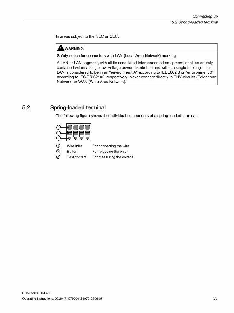
5.2 Spring-loaded terminal The following figure shows the individual components of a spring-loaded terminal:
① Wire inlet For connecting the wire ② Button For releasing the wire ③ Test contact For measuring the voltage
Connecting up 5.3 Power supply
SCALANCE XM-400 54 Operating Instructions, 05/2017, C79000-G8976-C306-07
5.3 Power supply
Notes on the power supply
WARNING
Incorrect power supply
If the device is connected to a redundant power supply (two separate power supplies), both must meet these requirements.
Never operate the device with AC voltage or DC voltage higher than 32 V DC.
CAUTION
Damage to the device due to overvoltage
The connector of the external power supply is not protected against strong electromagnetic pulses that can, for example, result from lightning strikes or switching large loads.
One of the tests used to attest the immunity of devices of the SCALANCE CM-400 IE switches to electromagnetic interference is the "surge immunity test" according to EN61000-4-5. This test requires overvoltage protection for the power supply lines. A suitable device is, for example, the Dehn Blitzductor BVT AVD 24, article number 918 422 or a comparable protective element.
Manufacturer: DEHN+SOEHNE GmbH+Co.KG, Hans-Dehn-Str.1, Postfach 1640, D92306 Neumarkt, Germany
Operate the SCALANCE XM-400 with suitable overvoltage protection.
Note
The extenders and pluggable transceivers are supplied with power via the basic device.
Information on the power supply ● The "L1" and "L2" LEDs indicate the current range of the power supply, see the section
"LEDs "L1" and "L2" (Page 30)".
● The power supply is connected using a 4-pin plug-in terminal block (spring-loaded terminal). The terminal block ships with the device and can also be ordered as a spare part.
● The power supply can be connected redundantly. Both inputs are isolated. There is no distribution of load. When a redundant power supply is used, the power supply unit with the higher output voltage supplies the SCALANCE XM-400 alone.
● The power supply is connected over a high resistance with the enclosure to allow an ungrounded set up. The two power inputs are non-floating.
● To wire up the power connector, use a copper cable of category 18-12 AWG or cable with a cross-section of 0.75 to 2.5 mm².
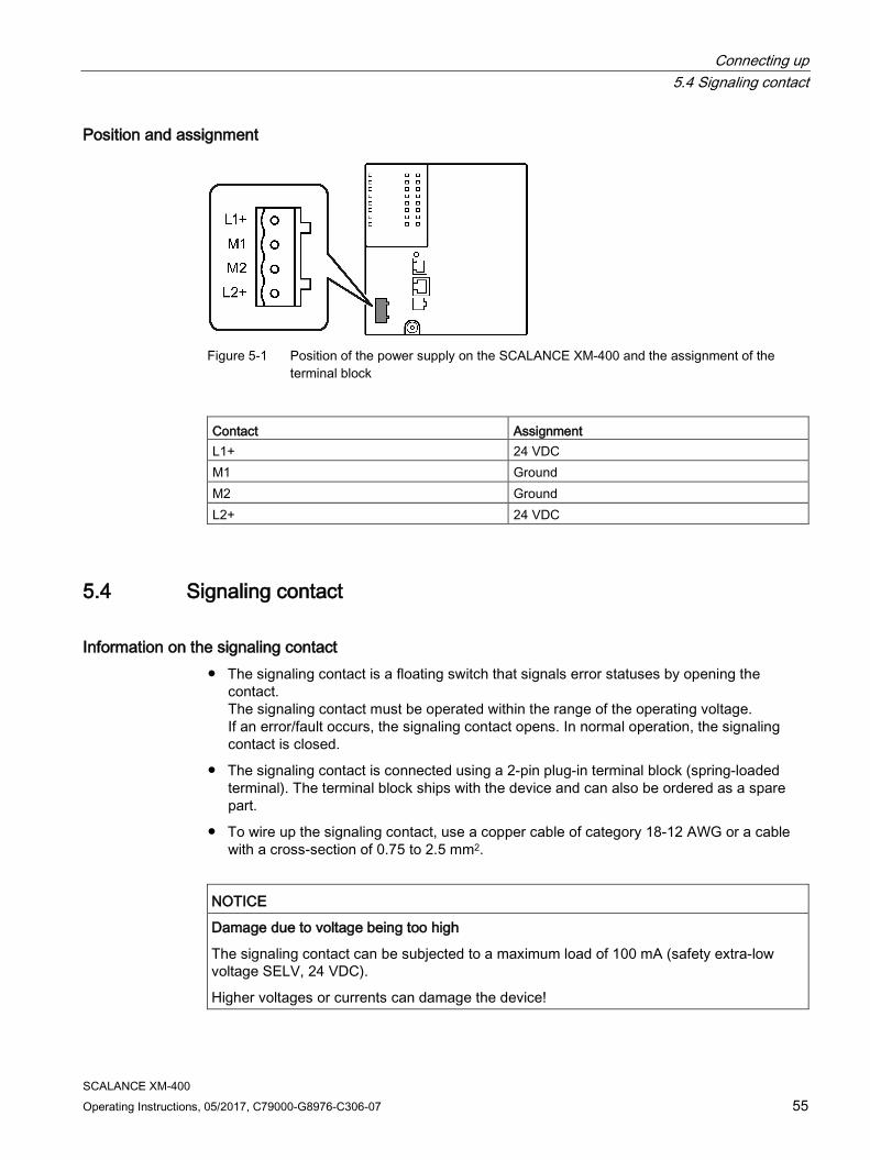
Connecting up 5.4 Signaling contact
SCALANCE XM-400 Operating Instructions, 05/2017, C79000-G8976-C306-07 55
Position and assignment
Figure 5-1 Position of the power supply on the SCALANCE XM-400 and the assignment of the
terminal block
Contact Assignment L1+ 24 VDC M1 Ground M2 Ground L2+ 24 VDC
5.4 Signaling contact
Information on the signaling contact ● The signaling contact is a floating switch that signals error statuses by opening the
contact. The signaling contact must be operated within the range of the operating voltage. If an error/fault occurs, the signaling contact opens. In normal operation, the signaling contact is closed.
● The signaling contact is connected using a 2-pin plug-in terminal block (spring-loaded terminal). The terminal block ships with the device and can also be ordered as a spare part.
● To wire up the signaling contact, use a copper cable of category 18-12 AWG or a cable with a cross-section of 0.75 to 2.5 mm2.
NOTICE
Damage due to voltage being too high
The signaling contact can be subjected to a maximum load of 100 mA (safety extra-low voltage SELV, 24 VDC).
Higher voltages or currents can damage the device!

Connecting up 5.5 Serial interface
SCALANCE XM-400 56 Operating Instructions, 05/2017, C79000-G8976-C306-07
Position and assignment
Figure 5-2 Position of the signaling contact on the SCALANCE XM-400 and the assignment of the
terminal block
Pin number Assignment Pin 1 F1 Pin 2 F2
Signaling faults ● The signaling of errors by the signaling contact is synchronized with the fault LED "F",
see section ""F" LED (Page 29)". All errors that the fault LED "F" indicates (freely configurable) are also signaled by the signaling contact.
● If an internal fault occurs, the fault LED "F" lights up and the signaling contact opens.
● If you connect a communications node to an unmonitored port or disconnect it, this does not cause an error message.
● The signaling contact remains open until one of the following events occurs:
– The problem is eliminated.
– The current status is entered in the fault mask as the new desired status.
5.5 Serial interface
Information on the serial interface ● Via the serial interface on the device (RJ-11 jack), you can access the CLI of the device
directly via an RS-232 (115200 8N1) connection without assigning an IP address.
● Access to the device is also possible independent of the Ethernet ports.
● To connect the serial interface to the PC, you require a cable with an RJ-11 plug and 9-pin D-sub female connector. The connecting cable for the serial interface ships with the device and can also be ordered as a spare part.

Connecting up 5.5 Serial interface
SCALANCE XM-400 Operating Instructions, 05/2017, C79000-G8976-C306-07 57
Position and assignment
Figure 5-3 Position and pin assignment of the serial interface (RJ-11 jack) on the SCALANCE XM-
400 and the pin assignment of the D-sub female connector.
Assignment of the terminal block The supplied connecting cable has the following assignment: Contact Pin assignment of the RJ-11 plug Pin assignment of the D-sub female con-
nector 1 - - 2 - TD (Transmit Data) 3 TD (Transmit Data) RD (Receive Data) 4 SG (Signal Ground) - 5 RD (Receive Data) SG (Signal Ground) 6 - - 7 - 8 - 9 -
Note Pin assignment of the RJ-11 jack on the device
The RJ-11 jack on the device has a pinout to match the RJ-11 plug of the supplied connecting cable.

Connecting up 5.6 Out-of-band interface
SCALANCE XM-400 58 Operating Instructions, 05/2017, C79000-G8976-C306-07
5.6 Out-of-band interface
Information on the out-of-band interface ● The out-of-band interface is an RJ-45 Ethernet port on the CPU module. The out-of-band
interface is not used for routing or switching.
● Access to the device is also possible independent of the other Ethernet ports.
● The out-of-band interface allows direct IP access to the WBM of the device.
Position and assignment
Figure 5-4 Position and pin assignment of the out-of-band interface (RJ-45 jack) on the SCALANCE
XM-400.
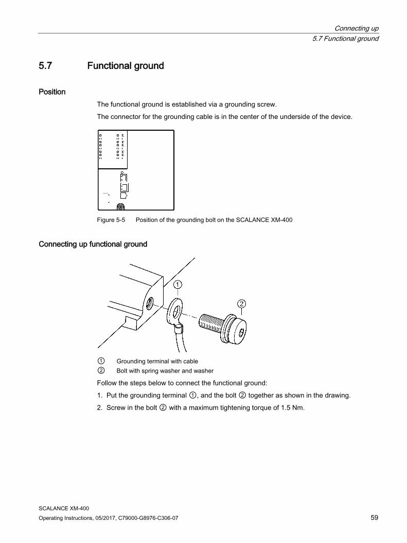
Connecting up 5.7 Functional ground
SCALANCE XM-400 Operating Instructions, 05/2017, C79000-G8976-C306-07 59
5.7 Functional ground
Position The functional ground is established via a grounding screw.
The connector for the grounding cable is in the center of the underside of the device.
Figure 5-5 Position of the grounding bolt on the SCALANCE XM-400
Connecting up functional ground
① Grounding terminal with cable ② Bolt with spring washer and washer
Follow the steps below to connect the functional ground:
1. Put the grounding terminal ①, and the bolt ② together as shown in the drawing.
2. Screw in the bolt ② with a maximum tightening torque of 1.5 Nm.

Connecting up 5.7 Functional ground
SCALANCE XM-400 60 Operating Instructions, 05/2017, C79000-G8976-C306-07
SCALANCE XM-400 Operating Instructions, 05/2017, C79000-G8976-C306-07 61
Upkeep and maintenance 6 6.1 Downloading new firmware using TFTP without WBM and CLI
Firmware The firmware is signed and encrypted. This ensures that only firmware created by Siemens can be downloaded to the device.
Procedure with Microsoft Windows Using TFTP, you can supply a device with new firmware even when it cannot be reached using WBM or CLI. This section explains the procedure based on the example of Microsoft Windows.
Follow the steps below to load new firmware using TFTP:
1. Turn off the power to the device.
2. Now press the "SELECT/SET" button and reconnect the power to the device while holding down the button.
3. Hold down the button until the red fault LED "F" starts to flash after approximately 30 seconds.
4. Now release the button. The bootloader of the device waits in this status for a new firmware file that you can download by TFTP.
5. Connect a PC to the out-band interface of the device via an Ethernet cable.
6. Assign an IP address to the device using DHCP or the Primary Setup Tool.
7. Open a Windows command prompt and change to the directory where the file with the new firmware is located and then execute the following command : tftp -i <IP address> put <firmware file>
Note
You can enable TFTP in Microsoft Windows as follows:
"Control Panel" > "Programs and Features" > "Turn Windows features on or off" > "TFTP Client".
8. Once the firmware has been transferred completely to the device and validated, there is an automatic restart on the device. This may take several minutes.
Upkeep and maintenance 6.2 Restoring the factory settings
SCALANCE XM-400 62 Operating Instructions, 05/2017, C79000-G8976-C306-07
6.2 Restoring the factory settings
NOTICE
Previous settings
If you reset, all the settings you have made will be overwritten by factory defaults.
NOTICE
Inadvertent reset
An inadvertent reset can cause disturbances and failures in the configured network.
Restoring the factory settings during the startup phase
NOTICE
Reset despite disabled "SELECT/SET" button
Using the "SELECT/SET" button, you can always reset the device parameters to the factory defaults during the startup phase of the device. This applies also if the "Reset to Factory Defaults" function was disabled in the configuration. This allows you to reset the device to the factory defaults in an emergency.
If the function has been disabled in the configuration, it is only disabled on completion of the startup phase.
To reset the device to the factory defaults during the startup phase, follow the steps below:
1. Turn off the power to the device.
2. Now press the "SELECT/SET" button and reconnect the power to the device while holding down the button.
3. Hold down the button until the red error LED "F" stops flashing and is permanently lit.
4. Now release the button and wait until the fault LED "F" goes off again.
5. The device starts automatically with the factory defaults.
Restoring the factory defaults during operation You can also reset the device to the factory defaults during operation, see section "SELECT / SET button (Page 25)".
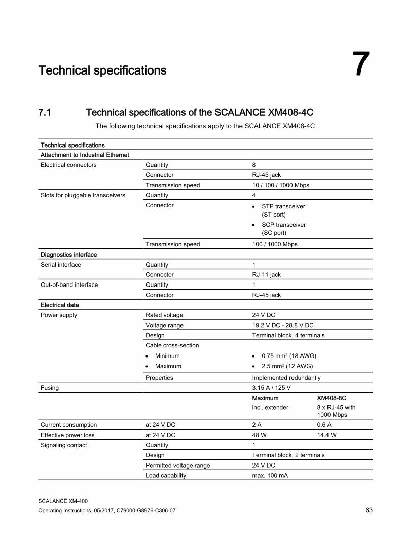
SCALANCE XM-400 Operating Instructions, 05/2017, C79000-G8976-C306-07 63
Technical specifications 7 7.1 Technical specifications of the SCALANCE XM408-4C
The following technical specifications apply to the SCALANCE XM408-4C.
Technical specifications Attachment to Industrial Ethernet Electrical connectors Quantity 8
Connector RJ-45 jack Transmission speed 10 / 100 / 1000 Mbps
Slots for pluggable transceivers Quantity 4 Connector • STP transceiver
(ST port) • SCP transceiver
(SC port)
Transmission speed 100 / 1000 Mbps Diagnostics interface Serial interface
Quantity 1 Connector RJ-11 jack
Out-of-band interface Quantity 1 Connector RJ-45 jack
Electrical data Power supply Rated voltage 24 V DC
Voltage range 19.2 V DC - 28.8 V DC Design Terminal block, 4 terminals Cable cross-section • Minimum • Maximum
• 0.75 mm2 (18 AWG) • 2.5 mm2 (12 AWG)
Properties Implemented redundantly Fusing 3.15 A / 125 V Maximum
incl. extender XM408-8C 8 x RJ-45 with 1000 Mbps
Current consumption at 24 V DC 2 A 0.6 A Effective power loss at 24 V DC 48 W 14.4 W Signaling contact Quantity 1
Design Terminal block, 2 terminals Permitted voltage range 24 V DC Load capability max. 100 mA
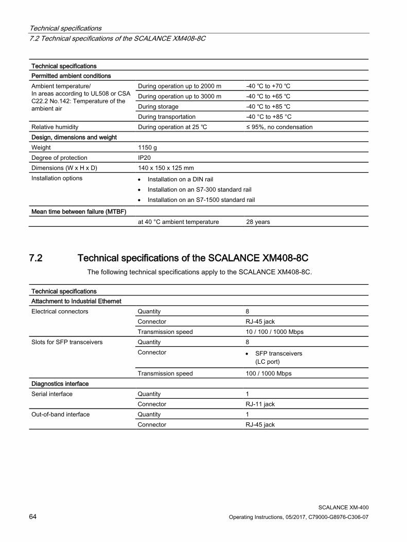
Technical specifications 7.2 Technical specifications of the SCALANCE XM408-8C
SCALANCE XM-400 64 Operating Instructions, 05/2017, C79000-G8976-C306-07
Technical specifications Permitted ambient conditions Ambient temperature/ In areas according to UL508 or CSA C22.2 No.142: Temperature of the ambient air
During operation up to 2000 m -40 ℃ to +70 ℃ During operation up to 3000 m -40 ℃ to +65 ℃ During storage -40 ℃ to +85 ℃ During transportation -40 °C to +85 °C
Relative humidity During operation at 25 ℃ ≤ 95%, no condensation Design, dimensions and weight Weight 1150 g Degree of protection IP20 Dimensions (W x H x D) 140 x 150 x 125 mm Installation options • Installation on a DIN rail
• Installation on an S7-300 standard rail • Installation on an S7-1500 standard rail
Mean time between failure (MTBF) at 40 °C ambient temperature 28 years
7.2 Technical specifications of the SCALANCE XM408-8C The following technical specifications apply to the SCALANCE XM408-8C.
Technical specifications Attachment to Industrial Ethernet Electrical connectors Quantity 8
Connector RJ-45 jack Transmission speed 10 / 100 / 1000 Mbps
Slots for SFP transceivers Quantity 8 Connector • SFP transceivers
(LC port)
Transmission speed 100 / 1000 Mbps Diagnostics interface Serial interface
Quantity 1 Connector RJ-11 jack
Out-of-band interface Quantity 1 Connector RJ-45 jack
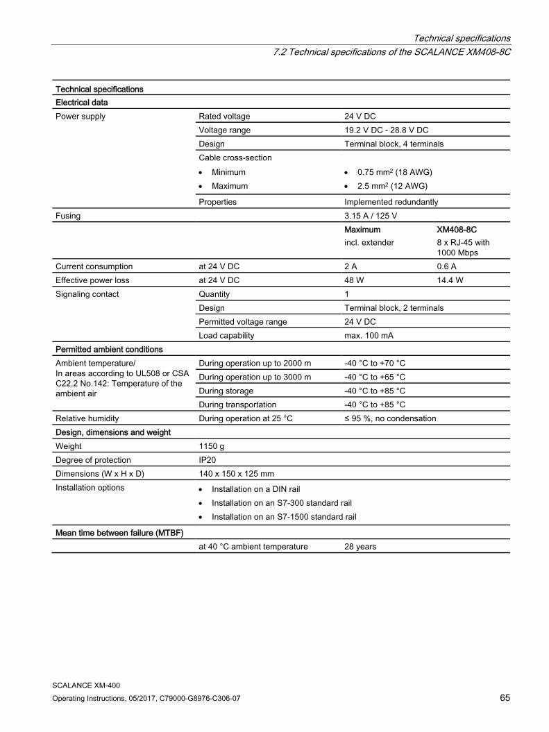
Technical specifications 7.2 Technical specifications of the SCALANCE XM408-8C
SCALANCE XM-400 Operating Instructions, 05/2017, C79000-G8976-C306-07 65
Technical specifications Electrical data Power supply Rated voltage 24 V DC
Voltage range 19.2 V DC - 28.8 V DC Design Terminal block, 4 terminals Cable cross-section • Minimum • Maximum
• 0.75 mm2 (18 AWG) • 2.5 mm2 (12 AWG)
Properties Implemented redundantly Fusing 3.15 A / 125 V Maximum
incl. extender XM408-8C 8 x RJ-45 with 1000 Mbps
Current consumption at 24 V DC 2 A 0.6 A Effective power loss at 24 V DC 48 W 14.4 W Signaling contact Quantity 1
Design Terminal block, 2 terminals Permitted voltage range 24 V DC Load capability max. 100 mA
Permitted ambient conditions Ambient temperature/ In areas according to UL508 or CSA C22.2 No.142: Temperature of the ambient air
During operation up to 2000 m -40 °C to +70 °C During operation up to 3000 m -40 °C to +65 °C During storage -40 °C to +85 °C During transportation -40 °C to +85 °C
Relative humidity During operation at 25 °C ≤ 95 %, no condensation Design, dimensions and weight Weight 1150 g Degree of protection IP20 Dimensions (W x H x D) 140 x 150 x 125 mm Installation options • Installation on a DIN rail
• Installation on an S7-300 standard rail • Installation on an S7-1500 standard rail
Mean time between failure (MTBF) at 40 °C ambient temperature 28 years

Technical specifications 7.3 Technical specifications of the SCALANCE XM416-4C
SCALANCE XM-400 66 Operating Instructions, 05/2017, C79000-G8976-C306-07
7.3 Technical specifications of the SCALANCE XM416-4C The following technical specifications apply to the SCALANCE XM416-4C.
Technical specifications Attachment to Industrial Ethernet Electrical connectors Quantity 16
Connector RJ-45 jack Transmission speed 10 / 100 / 1000 Mbps
Slots for SFP transceivers Quantity 4 Connector • SFP transceivers
(LC port)
Transmission speed 100 / 1000 Mbps Diagnostics interface Serial interface
Quantity 1 Connector RJ-11 jack
Out-of-band interface Quantity 1 Connector RJ-45 jack
Electrical data Power supply Rated voltage 24 V DC
Voltage range 19.2 V DC - 28.8 V DC Design Terminal block, 4 terminals Cable cross-section • Minimum • Maximum
• 0.75 mm2 (18 AWG) • 2.5 mm2 (12 AWG)
Properties Implemented redundantly Fusing 3.15 A / 125 V Maximum
incl. extender XM416-4C 16 x RJ-45 with 1000 Mbps
Current consumption at 24 V DC 2 A 0.7 A Effective power loss at 24 V DC 48 W 16.8 W Signaling contact Quantity 1
Design Terminal block, 2 terminals Permitted voltage range 24 V DC Load capability max. 100 mA
Permitted ambient conditions Ambient temperature/ In areas according to UL508 or CSA C22.2 No.142: Temperature of the ambient air
During operation up to 2000 m -40 ℃ to +70 ℃ During operation up to 3000 m -40 ℃ to +65 ℃ During storage -40 ℃ to +85 ℃ During transportation -40 ℃ to +85 ℃
Relative humidity During operation at 25 ℃ ≤ 95%, no condensation
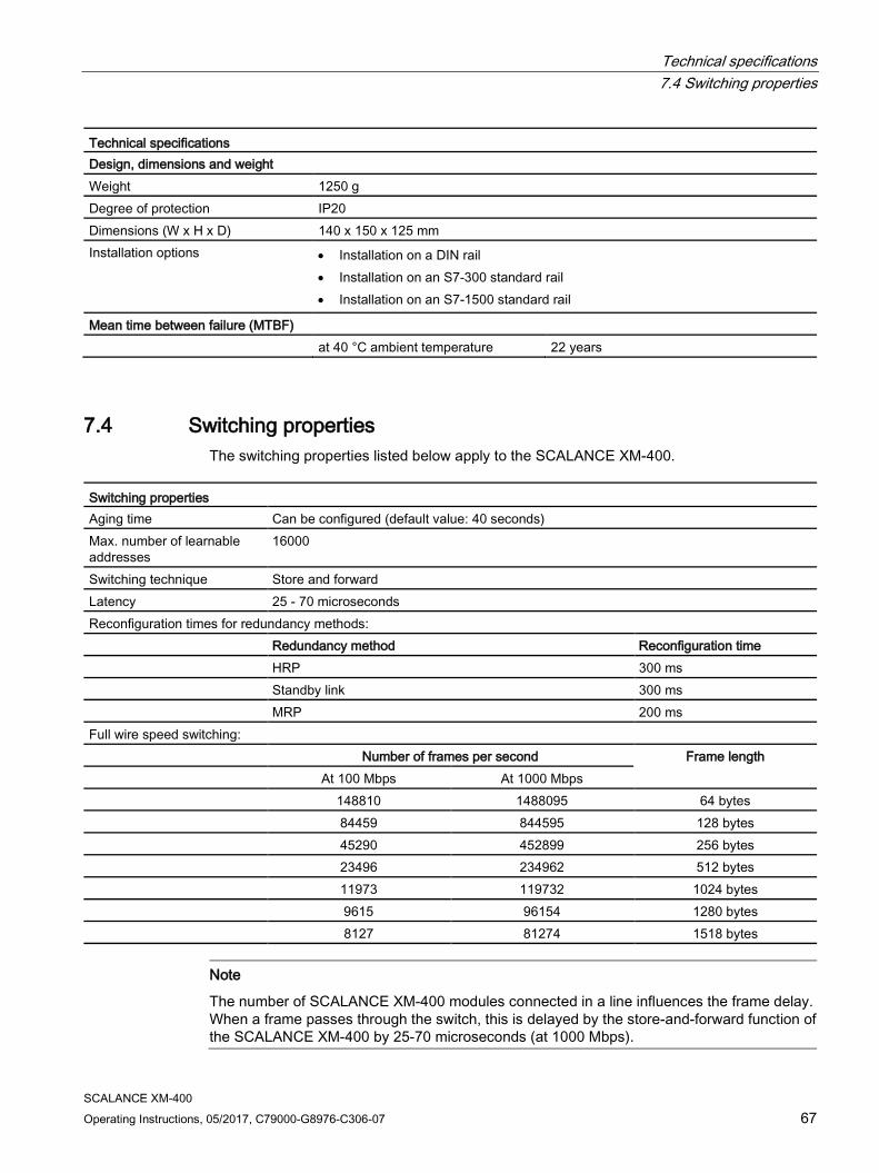
Technical specifications 7.4 Switching properties
SCALANCE XM-400 Operating Instructions, 05/2017, C79000-G8976-C306-07 67
Technical specifications Design, dimensions and weight Weight 1250 g Degree of protection IP20 Dimensions (W x H x D) 140 x 150 x 125 mm Installation options • Installation on a DIN rail
• Installation on an S7-300 standard rail • Installation on an S7-1500 standard rail
Mean time between failure (MTBF) at 40 °C ambient temperature 22 years
7.4 Switching properties The switching properties listed below apply to the SCALANCE XM-400.
Switching properties Aging time Can be configured (default value: 40 seconds) Max. number of learnable addresses
16000
Switching technique Store and forward Latency 25 - 70 microseconds Reconfiguration times for redundancy methods: Redundancy method Reconfiguration time HRP 300 ms Standby link 300 ms MRP 200 ms Full wire speed switching:
Number of frames per second Frame length At 100 Mbps At 1000 Mbps 148810 1488095 64 bytes 84459 844595 128 bytes 45290 452899 256 bytes 23496 234962 512 bytes 11973 119732 1024 bytes 9615 96154 1280 bytes 8127 81274 1518 bytes
Note
The number of SCALANCE XM-400 modules connected in a line influences the frame delay. When a frame passes through the switch, this is delayed by the store-and-forward function of the SCALANCE XM-400 by 25-70 microseconds (at 1000 Mbps).

Technical specifications 7.4 Switching properties
SCALANCE XM-400 68 Operating Instructions, 05/2017, C79000-G8976-C306-07
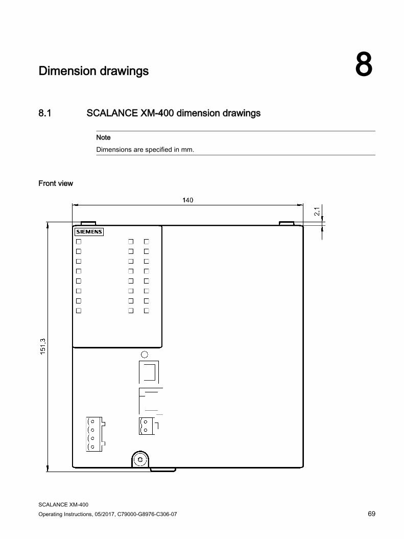
SCALANCE XM-400 Operating Instructions, 05/2017, C79000-G8976-C306-07 69
Dimension drawings 8 8.1 SCALANCE XM-400 dimension drawings
Note
Dimensions are specified in mm.
Front view
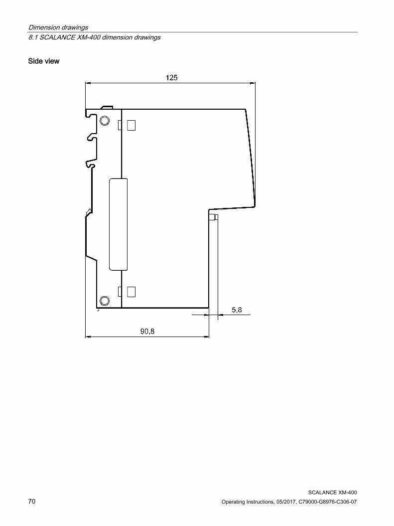
Dimension drawings 8.1 SCALANCE XM-400 dimension drawings
SCALANCE XM-400 70 Operating Instructions, 05/2017, C79000-G8976-C306-07
Side view
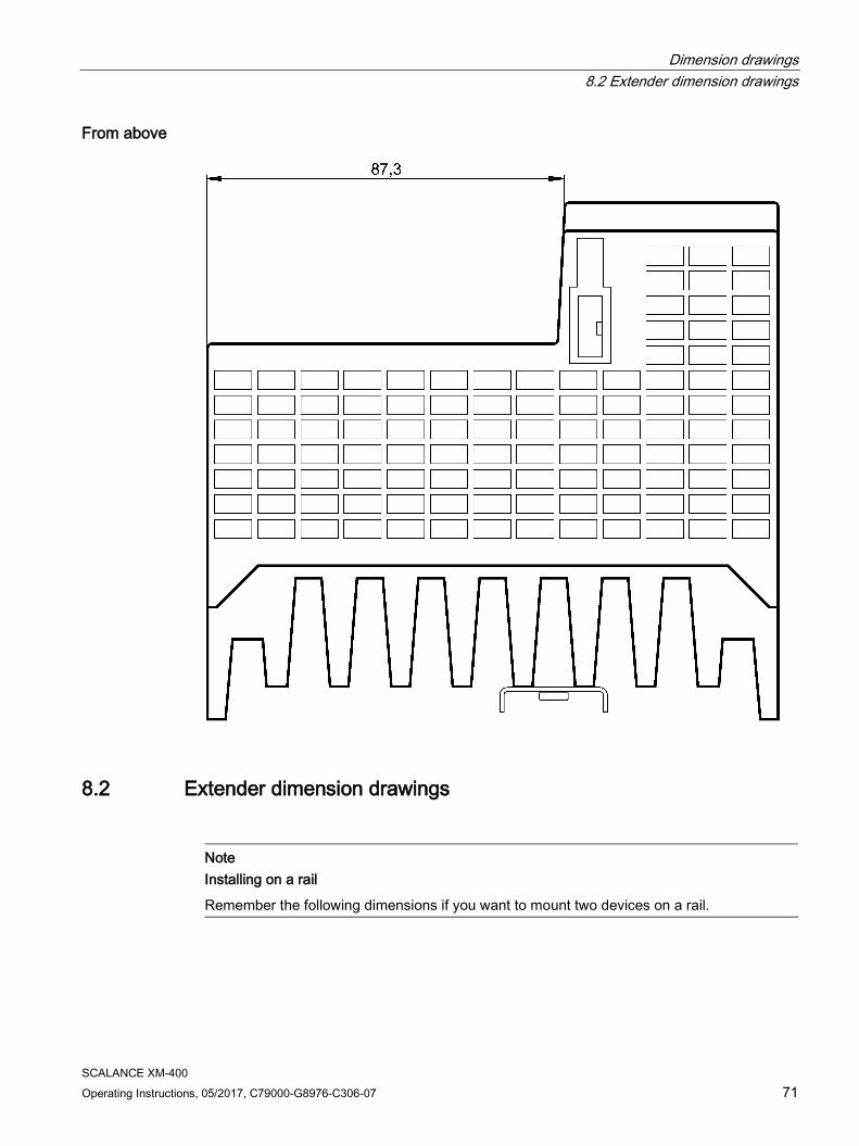
Dimension drawings 8.2 Extender dimension drawings
SCALANCE XM-400 Operating Instructions, 05/2017, C79000-G8976-C306-07 71
From above
8.2 Extender dimension drawings
Note Installing on a rail
Remember the following dimensions if you want to mount two devices on a rail.
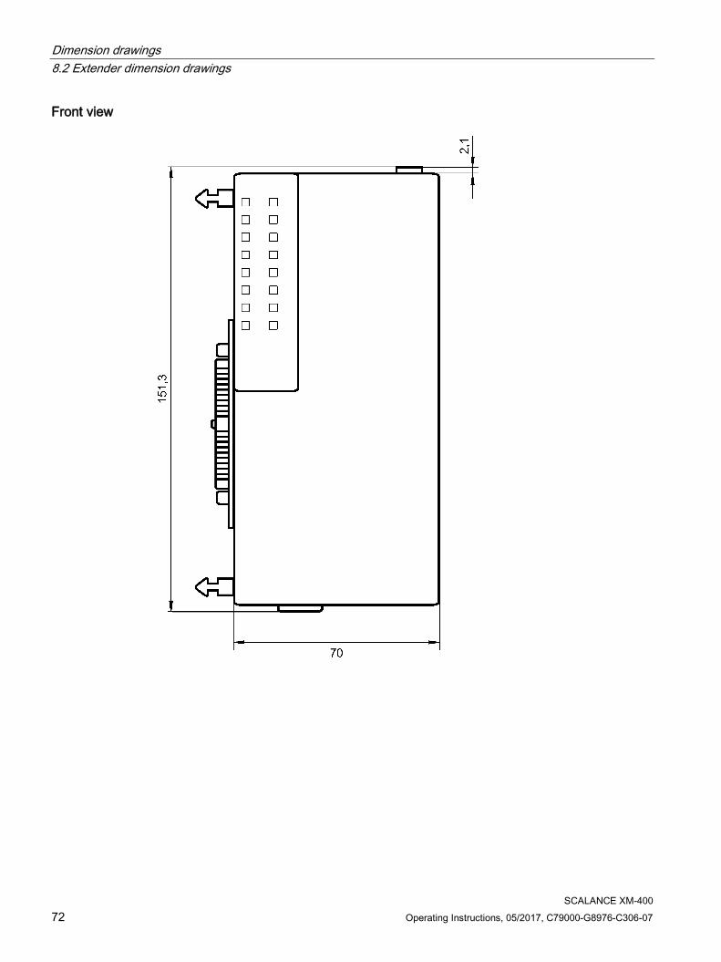
Dimension drawings 8.2 Extender dimension drawings
SCALANCE XM-400 72 Operating Instructions, 05/2017, C79000-G8976-C306-07
Front view
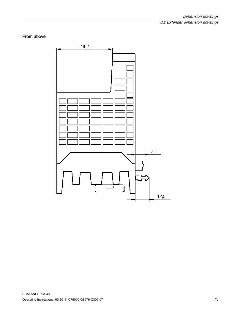
Dimension drawings 8.2 Extender dimension drawings
SCALANCE XM-400 Operating Instructions, 05/2017, C79000-G8976-C306-07 73
From above

Dimension drawings 8.2 Extender dimension drawings
SCALANCE XM-400 74 Operating Instructions, 05/2017, C79000-G8976-C306-07

SCALANCE XM-400 Operating Instructions, 05/2017, C79000-G8976-C306-07 75
Approvals A
The SIMATIC NET products described in these Operating Instructions have the approvals listed below.
Note Issued approvals on the type plate of the device
The specified approvals apply only when the corresponding mark is printed on the product. You can check which of the following approvals have been granted for your product by the markings on the type plate.
EC declaration of conformity The SIMATIC NET products described in these operating instructions meet the requirements and safety objectives of the following EC directives and comply with the harmonized European standards (EN) which are published in the official documentation of the European Union.
● 2014/34/EU (ATEX explosion protection directive)
Directive of the European Parliament and the Council of 26 February 2014 on the approximation of the laws of the member states concerning equipment and protective systems intended for use in potentially explosive atmospheres, official journal of the EU L96, 29/03/2014, pages. 309-356
● 2014/30/EU (EMC)
EMC directive of the European Parliament and of the Council of February 26, 2014 on the approximation of the laws of the member states relating to electromagnetic compatibility; official journal of the EU L96, 29/03/2014, pages. 79-106
● 2011/65/EU (RoHS)
Directive of the European Parliament and of the Council of 8 June 2011 on the restriction of the use of certain hazardous substances in electrical and electronic equipment
You will find the EC declaration of conformity for these products on the Internet pages of Siemens Industry Online Support (http://support.automation.siemens.com/WW/view/en/33118389/134200).
The EC Declaration of Conformity is available for all responsible authorities at:
Siemens Aktiengesellschaft
Division Process Industries and Drives Process Automation DE-76181 Karlsruhe Germany
Approvals
SCALANCE XM-400 76 Operating Instructions, 05/2017, C79000-G8976-C306-07
EC directives SIMATIC NET products meet the requirements and aims of the following EC directives.
EMC directive (electromagnetic compatibility) Until 19.042016 the SIMATIC NET products described in these operating instructions meet the requirements of the EC Directive:2004/108/EC "Electromagnetic Compatibility” (EMC directive) and as of 20.04.2016 the EC directive 2014/30/EU. Field of application Requirements
Emission Immunity to interference Industry EN 61000-6-4 EN 61000-6-2
You will find the current versions of the standards in the currently valid EC declaration of conformity.
ATEX (explosion protection directive)
WARNING
When using SIMATIC NET products in hazardous area zone 2, make absolutely sure that the associated conditions in the following document are adhered to:
"SIMATIC NET Product Information Use of subasseblies/modules in a Zone 2 Hazardous Area".
You will find this document • on the data medium that ships with some devices. • on the Internet pages of Siemens Industry Online Support
(http://support.automation.siemens.com/WW/view/en).
Enter the document identification number C234 as the search term.
The SIMATIC NET products meet the requirements of the EC directive 94/9/EC "Equipment and Protective Devices for Use in Potentially Explosive Atmospheres”. and as of 20.04.2016 the EC directive 2014/34/EU.
ATEX classification:
II 3 G Ex nA IIC T4 Gc
KEMA 07ATEX0145 X
The products meet the requirements of the following standards:
● EN 60079-15 (electrical apparatus for potentially explosive atmospheres; Type of protection "n")
● EN 60079-0 (Explosive atmospheres - Part 0: Equipment - General requirements)
You will find the current versions of the standards in the currently valid ATEX certificates.

Approvals
SCALANCE XM-400 Operating Instructions, 05/2017, C79000-G8976-C306-07 77
IECEx The SIMATIC NET products meet the requirements of explosion protection according to IECEx.
IECEx classification:
Ex nA IIC T4 Gc
DEK 14.0025X
The products meet the requirements of the following standards:
● IEC 60079-15 (Explosive atmospheres - Part 15: Equipment protection by type of protection "n")
● IEC 60079-0 (Explosive atmospheres - Part 0: Equipment - General requirements)
You will find the current versions of the standards in the currently valid IECEx certificates.
FM The product meets the requirements of the standards:
● Factory Mutual Approval Standard Class Number 3611
● FM Hazardous (Classified) Location Electrical Equipment: Non Incendive / Class I / Division 2 / Groups A,B,C,D / T4 and Non Incendive / Class I / Zone 2 / Group IIC / T4
cULus approval for industrial control equipment cULus Listed IND. CONT. EQ.
Underwriters Laboratories Inc. complying with
● UL 508
● CSA C22.2 No. 142-M1987
Report no. E85972
cULus Approval for Information Technology Equipment cULus Listed I. T. E.
Underwriters Laboratories Inc. complying with
● UL 60950-1 (Information Technology Equipment)
● CSA C22.2 No. 60950-1-03
Report no. E115352
Approvals
SCALANCE XM-400 78 Operating Instructions, 05/2017, C79000-G8976-C306-07
cULus Approval Hazardous Location cULus Listed I. T. E. FOR HAZ. LOC.
Underwriters Laboratories Inc. complying with
● UL 60950-1 (Information Technology Equipment)
● ANSI/ISA 12.12.01-2007
● CSA C22.2 No. 213-M1987
Approved for use in Cl. 1, Div. 2, GP A, B, C, D T4 Cl. 1, Zone 2, GP IIC T4
Report no. E240480
RCM The product meets the requirements of the AS/NZS 2064 standard (Class A).
MSIP 요구사항 - For Korea only A급 기기(업무용 방송통신기자재)
이 기기는 업무용(A급) 전자파 적합기기로서 판매자 또는 사용자는 이 점을 주의하시기 바라며, 가정 외의 지역에서 사용하는것을 목적으로 합니다.
Marking for the customs union EAC (Eurasian Conformity)
Customs union of Russia, Belarus and Kazakhstan
Declaration of the conformity according to the technical regulations of the customs union (TR CU)
Safety of electrical equipment In the version put into circulation by Siemens AG, the SIMATIC NET products described in these Operating Instructions conform to the regulations of the following European directive:
● EN 60950-1 Information technology equipment - Safety - Part 1: General requirements
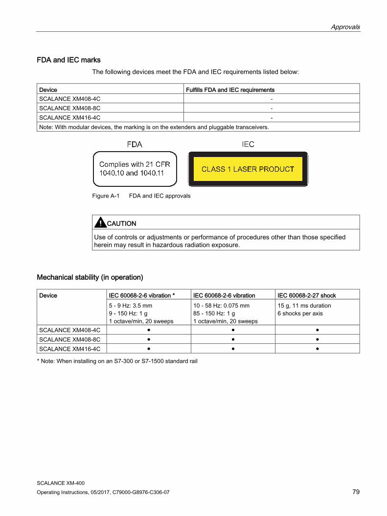
Approvals
SCALANCE XM-400 Operating Instructions, 05/2017, C79000-G8976-C306-07 79
FDA and IEC marks The following devices meet the FDA and IEC requirements listed below:
Device Fulfills FDA and IEC requirements SCALANCE XM408-4C - SCALANCE XM408-8C - SCALANCE XM416-4C - Note: With modular devices, the marking is on the extenders and pluggable transceivers.
Figure A-1 FDA and IEC approvals
CAUTION
Use of controls or adjustments or performance of procedures other than those specified herein may result in hazardous radiation exposure.
Mechanical stability (in operation) Device
IEC 60068-2-6 vibration * IEC 60068-2-6 vibration IEC 60068-2-27 shock 5 - 9 Hz: 3.5 mm 9 - 150 Hz: 1 g 1 octave/min, 20 sweeps
10 - 58 Hz: 0.075 mm 85 - 150 Hz: 1 g 1 octave/min, 20 sweeps
15 g, 11 ms duration 6 shocks per axis
SCALANCE XM408-4C ● ● ● SCALANCE XM408-8C ● ● ● SCALANCE XM416-4C ● ● ● * Note: When installing on an S7-300 or S7-1500 standard rail
Approvals
SCALANCE XM-400 80 Operating Instructions, 05/2017, C79000-G8976-C306-07
Installation guidelines The devices meet the requirements if you adhere to the installation and safety instructions contained in this documentation and in the following documentation when installing and operating the devices.
● "Industrial Ethernet / PROFINET Industrial Ethernet" System Manual
● "Industrial Ethernet / PROFINET - Passive network components" System Manual
You will find information on the system manuals in the section "AUTOHOTSPOT", in "Further documentation".
● "EMC Installation Guidelines" configuration manual
ID = 60612658 (http://support.automation.siemens.com/WW/view/en/60612658)
WARNING
Personal injury and property damage can occur
The installation of expansions that are not approved for SIMATIC NET products or their target systems may violate the requirements and regulations for safety and electromagnetic compatibility.
Only use expansions that are approved for the system.
Note
The test was performed with a device and a connected communications partner that also meets the requirements of the standards listed above.
When operating the device with a communications partner that does not comply with these standards, adherence to the corresponding values cannot be guaranteed.
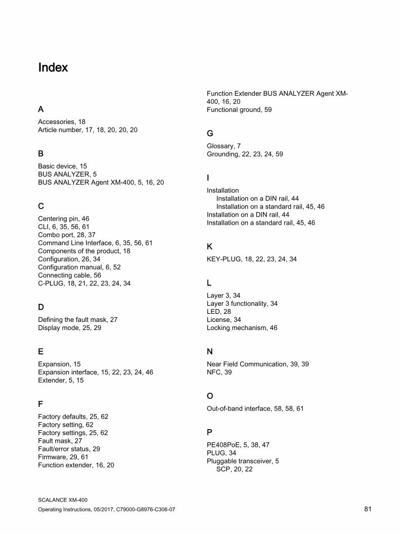
SCALANCE XM-400 Operating Instructions, 05/2017, C79000-G8976-C306-07 81
Index
A Accessories, 18 Article number, 17, 18, 20, 20, 20
B Basic device, 15 BUS ANALYZER, 5 BUS ANALYZER Agent XM-400, 5, 16, 20
C Centering pin, 46 CLI, 6, 35, 56, 61 Combo port, 28, 37 Command Line Interface, 6, 35, 56, 61 Components of the product, 18 Configuration, 26, 34 Configuration manual, 6, 52 Connecting cable, 56 C-PLUG, 18, 21, 22, 23, 24, 34
D Defining the fault mask, 27 Display mode, 25, 29
E Expansion, 15 Expansion interface, 15, 22, 23, 24, 46 Extender, 5, 15
F Factory defaults, 25, 62 Factory setting, 62 Factory settings, 25, 62 Fault mask, 27 Fault/error status, 29 Firmware, 29, 61 Function extender, 16, 20
Function Extender BUS ANALYZER Agent XM-400, 16, 20 Functional ground, 59
G Glossary, 7 Grounding, 22, 23, 24, 59
I Installation
Installation on a DIN rail, 44 Installation on a standard rail, 45, 46
Installation on a DIN rail, 44 Installation on a standard rail, 45, 46
K KEY-PLUG, 18, 22, 23, 24, 34
L Layer 3, 34 Layer 3 functionality, 34 LED, 28 License, 34 Locking mechanism, 46
N Near Field Communication, 39, 39 NFC, 39
O Out-of-band interface, 58, 58, 61
P PE408PoE, 5, 38, 47 PLUG, 34 Pluggable transceiver, 5
SCP, 20, 22

Index
SCALANCE XM-400 82 Operating Instructions, 05/2017, C79000-G8976-C306-07
SFP, 23, 24 STP, 20, 22
PoE, 38, 47 Port extender PE408PoE, 38, 47
PoE power supply, 5, 5, 20, 20, 38, 38, 47, 47 PoE power supply unit, 5, 20, 38, 47 Port extender, 5, 5, 16 Port extender PE408PoE, 38, 47 Power over Ethernet, 38, 47
Port extender PE408PoE, 38, 47 Power supply, 5, 5, 20, 20, 38, 38, 47, 47, 54 Power supply unit, 5, 20, 38, 47 PS9230 PoE, 5, 20, 38, 47 PS924 PoE, 5, 20, 38, 47
R Redundancy manager, 27 Reset device, 25, 62, 62 Reset to Factory Defaults, 62 Restore Factory Defaults, 26
S S7-1500, 46 S7-300, 45 Safety notices
for installation, 41 general, 9 Use in hazardous areas, 9, 41, 51 when connecting up, 51
SCALANCE PS9230 PoE, 5 SCALANCE PS924 PoE, 5 SCP, 5 SCP transceiver, 20, 22 Securing location, 22, 23, 24, 45, 46 Securing screw, 18, 21, 22, 23, 24, 45, 46 SELECT / SET button, 25 SELECT/SET button, 30, 61, 62 Serial interface, 56, 56 SFP, 5 SFP transceiver, 23, 24 SFP transceiver slots, 15 SFP+, 5 Signaling contact, 29, 55 SIMATIC NET glossary, 7 SIMATIC NET manual, 7 Spare parts, 21 Spring-loaded terminal, 18, 21, 53, 54, 55 Startup phase, 26, 29, 62 STP, 5
STP transceiver, 20, 22 System manual, 6, 42, 80
T Transceiver, 5
W WBM, 6, 35, 58, 61 Web Based Management, 6, 35, 58, 61