Embed Size (px)
DESCRIPTION
OTHER BENEFITS: •Usedasmainorauxiliary •MountingonDINrail •Sealingterminalcoversfordirectprotection againstcontactwithliveparts •IKVventilationmoduleforpreventingexceededheating whencontactorsareusedside-by-side INTENDED USE: •Customerunitsindwelings •Businesspremises •Hotels •Hospitals •Shoppingcentres •Sportcentres •Productionhalls •Warehouses •Publicplaces ®
Citation preview
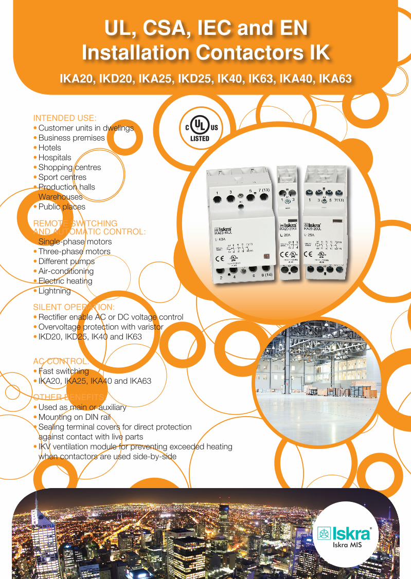
UL, CSA, IEC and ENInstallation Contactors IK
IKA20, IKD20, IKA25, IKD25, IK40, IK63, IKA40, IKA63
REMOTE SWITCHINGAND AUTOMATIC CONTROL:•Single-phasemotors•Three-phasemotors•Differentpumps•Air-conditioning•Electricheating•Lightning
SILENT OPERATION:•RectifierenableACorDCvoltagecontrol•Overvoltageprotectionwithvaristor•IKD20,IKD25,IK40andIK63
AC CONTROL:•Fastswitching•IKA20,IKA25,IKA40andIKA63
OTHER BENEFITS:•Usedasmainorauxiliary•MountingonDINrail•Sealingterminalcoversfordirectprotection againstcontactwithliveparts•IKVventilationmoduleforpreventingexceededheating whencontactorsareusedside-by-side
INTENDED USE:•Customerunitsindwelings•Businesspremises•Hotels•Hospitals•Shoppingcentres•Sportcentres•Productionhalls•Warehouses•Publicplaces
®
Tehnical Data
FIxED CAPACITORS FOR USE IN ELECTRONIC EqUIPMENT - TyPE KNG1914
Rated capacitance 5 μF 30 μF 75 μF
Tolerance of capacitance ± 10% (code K) ± 5% (code J) ± 10% (code K)
Rated voltage Ur1000 V DC at 85°C1100 V DC at 70°C
700 V DC at 85°C800 V DC at 70°C
700 V DC at 85°C800 V DC at 70°C
Max. repititive overvoltage (85°C) 1150 V DC - -
Repetitive overvoltage withstand (65°C) -830 V DC (for max. 3h/day,
I ripple = 0 A)830 V DC (for max. 3h day,
I ripple = 0 A)
Non repititive overvoltage withstand (25°C)1300 V DC (for max. 5 min.,
Iripple= 0 A)900 V DC (for max. 5 min.,
Iripple= 0 A)900 V DC (for max. 5 min.,
Iripple= 0 A)
Max. Irms (10 kHz, 70°C) 10 A 16 A 25 A
Test voltage (between terminals) 1.5xUr, 10 sec., 25°C 1.5xUr, 10 sec., 25°C 1.5xUr, 10 sec., 25°C
Test voltage (terminal to case) 2 kV, 50 Hz for 10 sec. 2 kV, 50 Hz for 10 sec. 2 kV, 50 Hz for 10 sec.
Max. Change of capacitance after 100,000 h -5% (Ur, 75°C) - -
Max. Change of capacitance after 30,000 h - -5% (700 V DC, 75°C) -5% (700 V DC, 75°C)
Pulse loading dU/dt (max.) 75 V/ μs 25 V/ μs 15 V/ μs
Ipeak 375 A 750 A 1125 A
Disspation factor tgδ≤ 10x10-4 at 1 kHz≤ 50x10-4 at 10 kHz
≤ 20x10-4 at 1 kHz≤ 150x10-4 at 10 kHz
≤ 30x10-4 at 1 kHz≤ 200x10-4 at 10 kHz
Insulation resistance≥ 6000 MΩ (at 500 V DC,
60 sec., 20°C)≥ 1000 MΩ (at 500 V DC,
60 sec., 20°C)≥ 400 MΩ (at 500 V DC,
60 sec., 20°C)
Self inductance (Ls) < 25 nH < 30 nH < 50 nH
Equivalent series resistance (ESR) of a capacitor measure 23°C, 10 kHz, typical value
7 mΩ 6 mΩ 4 mΩ
Climatic category 55/085/56 according to IEC 60068-1
Max. application temperature 85°C
Max. operating temperature (case) 105°C
Rated capacitance 5 µF 5 µF 10 µF 30 µF 50 µF 75 µF
Tolerance of capacitance ± 10% (code K) ± 5% (code J) ± 10% (code K) ± 5% (code J) ± 10% (code K) ± 10% (code K)
Rated voltage Ur1000 V DC at 85°C1100 V DC at 70°C
700 V DC at 85°C800 V DC at 70°C
450 V DC at 85°C500 V DC at 70°C
700 V DC at 85°C800 V DC at 70°C
900 V DC at 85°C1100 V DC at 70°C
700 V DC at 85°C800 V DC at 70°C
Max. repetitive overvoltage (85°C) 1150 V DC - 550 - - -
Repetitive overvoltage withstand (65°C) -
830 V DC(for max 3h/day
Iripple = 0 A)-
830 V DC(for max 3h/day
Iripple = 0 A)
1000 V DC(for max 3h/day
Iripple = 0 A)
830 V DC (for max 3h/day
Iripple = 0 A)
Non repetitive overvoltage withstand (25°C)
1300 V DC (for max 5 min.
900 V DC (for max 5 min.
600 V DC (for max 5 min.
900 V DC (for max 5 min.
1150 V DC (for max 5 min.
900 V DC (for max 5 min.
Iripple = 0 A) Iripple = 0 A) Iripple = 0 A) Iripple = 0 A) Iripple = 0 A) Iripple = 0 A)
Max. Irms (10 kHz, 70°C) 10 A 5 A 7 A 16 A 18 A 25 A
Test voltag (between terminals)
1.5 x Ur, 10 sec., 25°C
1.5 x Ur, 10 sec., 25°C
1.5 x Ur, 10 sec., 25°C
1.5 x Ur, 10 sec., 25°C
1.5 x Ur, 10 sec., 25°C
1.5 x Ur, 10 sec., 25°C
Test voltage(terminal to case)
2 kV, 50 Hz for 10 sec.
2 kV, 50 Hz for 10 sec.
2kV, 50 Hz for 10 sec.
2kV, 50 Hz for 10 sec.
2 kV, 50 Hz for 10 sec.
2 kV, 50 Hz for 10 sec.
Max. change of capacitance after 100,000 h
-5%(Ur, 75°C)
-5%(Ur, 75°C)
-5%(Ur, 75°C) - -5%
(850 V DC, 75°C) -
Max. change of capacitance after30,000 h
- - - -5% (700 V DC, 75°C) - -5% (700 V DC,
75°C)
Pulse loading dU/dt (max) 75 V/µs 60 V/µs 50 V/µs 25 V/µs 20 V/µs 15 V/µs
Ipeak 375 A 300 A 500 A 750 A 1000 A 1125 A
Dissipation factor tg δ ≤ 10x10-4 at 1 kHz≤ 50x10-4 at 10 kHz
≤ 10x10-4 at 1 kHz≤ 50x10-4 at 10
kHz≤ 10x10-4 at 1 kHz≤ 50x10-4 at 10 kHz
≤ 20x10-4 at 1 kHz≤ 150x10-4 at 10 kHz
≤ 25x10-4 at 1 kHz≤ 180x10-4 at 10 kHz
≤ 30x10-4 at 1 kHz≤ 200x10-4 at 10 kHz
Insulation resistance≥ 6000 MΩ
(at 500 V DC,60 sec., 20°C)
≥ 6000 MΩ(at 100 V DC,60 sec., 20°C)
≥ 3000 MΩ(at 100 V DC,60 sec., 20°C)
≥ 1000 MΩ(at 500 V DC,60 sec., 20°C)
≥ 600 MΩ(at 500 V DC,60 sec., 20°C)
≥ 400 MΩ(at 500 V DC,60 sec., 20°C)
Self inductance (Ls) < 25 nH < 25 nH < 25 nH < 30 nH < 50 nH < 50 nH
Equivalent series resistance (ESR) of a capacitor measure 23°C 10 kHz, typical value
7 mΩ 10 mΩ 8 mΩ 6 mΩ 5 mΩ 4 mΩ
DimensionsL x H x W (mm) 32 x 33 x 20 32 x 25.5 x 15 32 x 28 x 18 42 x 45 x 30 58.5 x 51 x 36 58.5 x 51 x 36
Raster R, R1, d (mm) 27.5 10.2 1.2 27.5 0 0.8 27.5 0 0.8 37.5 20.3 1 52.5 20.3 1.2 52.5 20.3 1.2
Climatic category 55/085/56 according to IEC 60068-1
Max. application temperature 85°C
Max. operating temperature (case) 105°C
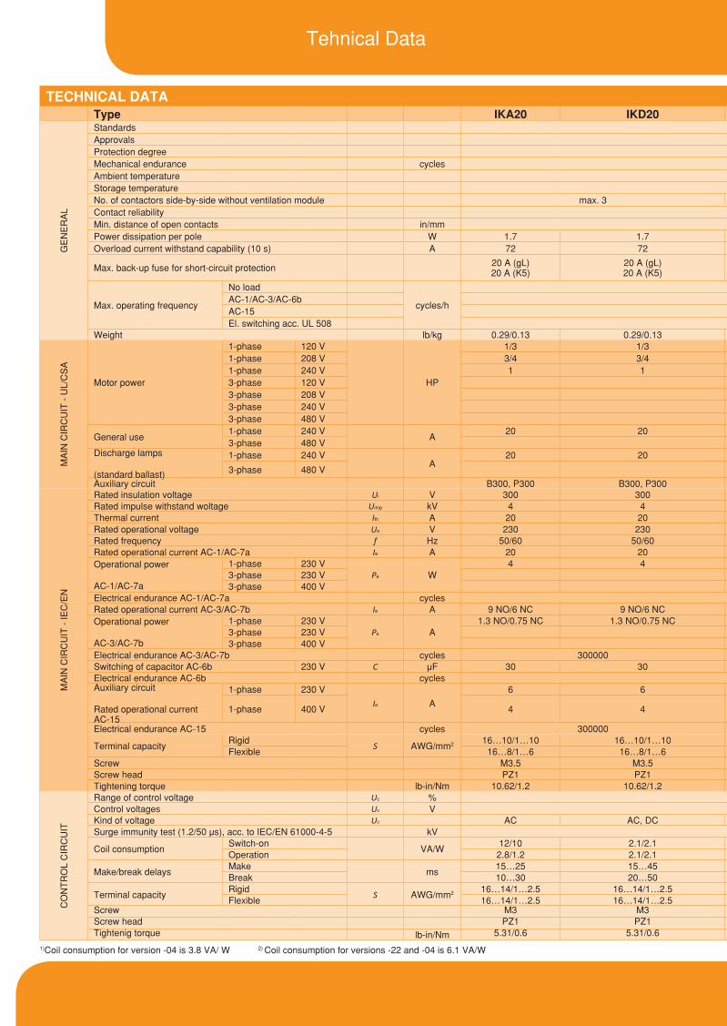
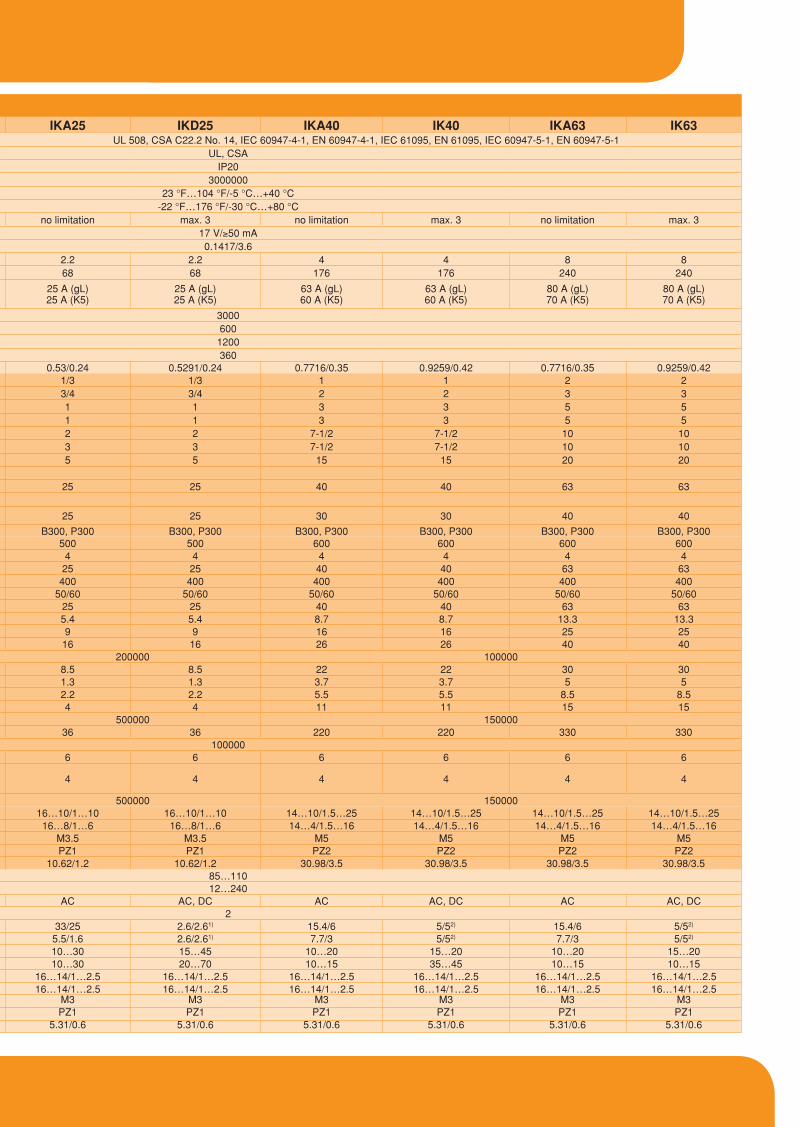
TECHNICAL DATAType IKA20 IKD20 IKA25 IKD25 IKA40 IK40 IKA63 IK63
GE
NE
RA
L
Standards UL 508, CSA C22.2 No. 14, IEC 60947-4-1, EN 60947-4-1, IEC 61095, EN 61095, IEC 60947-5-1, EN 60947-5-1Approvals UL, CSAProtection degree IP20Mechanical endurance cycles 3000000Ambient temperature 23 °F…104 °F/-5 °C…+40 °CStorage temperature -22 °F…176 °F/-30 °C…+80 °CNo. of contactors side-by-side without ventilation module max. 3 no limitation max. 3 no limitation max. 3 no limitation max. 3Contact reliability 17 V/≥50 mAMin. distance of open contacts in/mm 0.1417/3.6Power dissipation per pole W 1.7 1.7 2.2 2.2 4 4 8 8Overload current withstand capability (10 s) A 72 72 68 68 176 176 240 240
Max. back-up fuse for short-circuit protection 20 A (gL) 20 A (K5)
20 A (gL) 20 A (K5)
25 A (gL) 25 A (K5)
25 A (gL) 25 A (K5)
63 A (gL) 60 A (K5)
63 A (gL) 60 A (K5)
80 A (gL) 70 A (K5)
80 A (gL) 70 A (K5)
Max. operating frequency
No load
cycles/h
3000AC-1/AC-3/AC-6b 600AC-15 1200El. switching acc. UL 508 360
Weight lb/kg 0.29/0.13 0.29/0.13 0.53/0.24 0.5291/0.24 0.7716/0.35 0.9259/0.42 0.7716/0.35 0.9259/0.42
MA
IN C
IRC
UIT
- U
L/C
SA
Motor power
1-phase 120 V
HP
1/3 1/3 1/3 1/3 1 1 2 21-phase 208 V 3/4 3/4 3/4 3/4 2 2 3 31-phase 240 V 1 1 1 1 3 3 5 53-phase 120 V 1 1 3 3 5 53-phase 208 V 2 2 7-1/2 7-1/2 10 103-phase 240 V 3 3 7-1/2 7-1/2 10 103-phase 480 V 5 5 15 15 20 20
General use1-phase 240 V
A20 20
3-phase 480 V 25 25 40 40 63 63Discharge lamps
(standard ballast)
1-phase 240 VA
20 20
3-phase 480 V 25 25 30 30 40 40
Auxiliary circuit B300, P300 B300, P300 B300, P300 B300, P300 B300, P300 B300, P300 B300, P300 B300, P300
MA
IN C
IRC
UIT
- IE
C/E
N
Rated insulation voltage Ui V 300 300 500 500 600 600 600 600Rated impulse withstand woltage Uimp kV 4 4 4 4 4 4 4 4Thermal current Ith A 20 20 25 25 40 40 63 63Rated operational voltage Ue V 230 230 400 400 400 400 400 400Rated frequency f Hz 50/60 50/60 50/60 50/60 50/60 50/60 50/60 50/60Rated operational current AC-1/AC-7a Ie A 20 20 25 25 40 40 63 63Operational power
AC-1/AC-7a
1-phase 230 VPe W
4 4 5.4 5.4 8.7 8.7 13.3 13.33-phase 230 V 9 9 16 16 25 253-phase 400 V 16 16 26 26 40 40
Electrical endurance AC-1/AC-7a cycles 200000 100000Rated operational current AC-3/AC-7b Ie A 9 NO/6 NC 9 NO/6 NC 8.5 8.5 22 22 30 30Operational power
AC-3/AC-7b
1-phase 230 VPe A
1.3 NO/0.75 NC 1.3 NO/0.75 NC 1.3 1.3 3.7 3.7 5 53-phase 230 V 2.2 2.2 5.5 5.5 8.5 8.53-phase 400 V 4 4 11 11 15 15
Electrical endurance AC-3/AC-7b cycles 300000 500000 150000Switching of capacitor AC-6b 230 V C μF 30 30 36 36 220 220 330 330Electrical endurance AC-6b cycles 100000Auxiliary circuit
Rated operational current AC-15
1-phase 230 V
Ie A
6 6 6 6 6 6 6 6
1-phase 400 V 4 4 4 4 4 4 4 4
Electrical endurance AC-15 cycles 300000 500000 150000
Terminal capacityRigid
S AWG/mm2 16…10/1…10 16…10/1…10 16…10/1…10 16…10/1…10 14…10/1.5…25 14…10/1.5…25 14…10/1.5…25 14…10/1.5…25Flexible 16…8/1…6 16…8/1…6 16…8/1…6 16…8/1…6 14…4/1.5…16 14…4/1.5…16 14…4/1.5…16 14…4/1.5…16
Screw M3.5 M3.5 M3.5 M3.5 M5 M5 M5 M5Screw head PZ1 PZ1 PZ1 PZ1 PZ2 PZ2 PZ2 PZ2Tightening torque lb-in/Nm 10.62/1.2 10.62/1.2 10.62/1.2 10.62/1.2 30.98/3.5 30.98/3.5 30.98/3.5 30.98/3.5
CO
NT
RO
L C
IRC
UIT
Range of control voltage Uc % 85…110Control voltages Uc V 12…240Kind of voltage Uc AC AC, DC AC AC, DC AC AC, DC AC AC, DCSurge immunity test (1.2/50 μs), acc. to IEC/EN 61000-4-5 kV 2
Coil consumptionSwitch-on
VA/W12/10 2.1/2.1 33/25 2.6/2.61) 15.4/6 5/52) 15.4/6 5/52)
Operation 2.8/1.2 2.1/2.1 5.5/1.6 2.6/2.61) 7.7/3 5/52) 7.7/3 5/52)
Make/break delaysMake
ms15…25 15…45 10…30 15…45 10…20 15…20 10…20 15…20
Break 10…30 20…50 10…30 20…70 10…15 35…45 10…15 10…15
Terminal capacityRigid
S AWG/mm2 16…14/1…2.5 16…14/1…2.5 16…14/1…2.5 16…14/1…2.5 16…14/1…2.5 16…14/1…2.5 16…14/1…2.5 16…14/1…2.5Flexible 16…14/1…2.5 16…14/1…2.5 16…14/1…2.5 16…14/1…2.5 16…14/1…2.5 16…14/1…2.5 16…14/1…2.5 16…14/1…2.5
Screw M3 M3 M3 M3 M3 M3 M3 M3Screw head PZ1 PZ1 PZ1 PZ1 PZ1 PZ1 PZ1 PZ1Tightenig torque lb-in/Nm 5.31/0.6 5.31/0.6 5.31/0.6 5.31/0.6 5.31/0.6 5.31/0.6 5.31/0.6 5.31/0.6
1)Coil consumption for version -04 is 3.8 VA/ W 2) Coil consumption for versions -22 and -04 is 6.1 VA/W
TECHNICAL DATAType IKA20 IKD20 IKA25 IKD25 IKA40 IK40 IKA63 IK63
GE
NE
RA
L
Standards UL 508, CSA C22.2 No. 14, IEC 60947-4-1, EN 60947-4-1, IEC 61095, EN 61095, IEC 60947-5-1, EN 60947-5-1Approvals UL, CSAProtection degree IP20Mechanical endurance cycles 3000000Ambient temperature 23 °F…104 °F/-5 °C…+40 °CStorage temperature -22 °F…176 °F/-30 °C…+80 °CNo. of contactors side-by-side without ventilation module max. 3 no limitation max. 3 no limitation max. 3 no limitation max. 3Contact reliability 17 V/≥50 mAMin. distance of open contacts in/mm 0.1417/3.6Power dissipation per pole W 1.7 1.7 2.2 2.2 4 4 8 8Overload current withstand capability (10 s) A 72 72 68 68 176 176 240 240
Max. back-up fuse for short-circuit protection 20 A (gL) 20 A (K5)
20 A (gL) 20 A (K5)
25 A (gL) 25 A (K5)
25 A (gL) 25 A (K5)
63 A (gL) 60 A (K5)
63 A (gL) 60 A (K5)
80 A (gL) 70 A (K5)
80 A (gL) 70 A (K5)
Max. operating frequency
No load
cycles/h
3000AC-1/AC-3/AC-6b 600AC-15 1200El. switching acc. UL 508 360
Weight lb/kg 0.29/0.13 0.29/0.13 0.53/0.24 0.5291/0.24 0.7716/0.35 0.9259/0.42 0.7716/0.35 0.9259/0.42
MA
IN C
IRC
UIT
- U
L/C
SA
Motor power
1-phase 120 V
HP
1/3 1/3 1/3 1/3 1 1 2 21-phase 208 V 3/4 3/4 3/4 3/4 2 2 3 31-phase 240 V 1 1 1 1 3 3 5 53-phase 120 V 1 1 3 3 5 53-phase 208 V 2 2 7-1/2 7-1/2 10 103-phase 240 V 3 3 7-1/2 7-1/2 10 103-phase 480 V 5 5 15 15 20 20
General use1-phase 240 V
A20 20
3-phase 480 V 25 25 40 40 63 63Discharge lamps
(standard ballast)
1-phase 240 VA
20 20
3-phase 480 V 25 25 30 30 40 40
Auxiliary circuit B300, P300 B300, P300 B300, P300 B300, P300 B300, P300 B300, P300 B300, P300 B300, P300
MA
IN C
IRC
UIT
- IE
C/E
N
Rated insulation voltage Ui V 300 300 500 500 600 600 600 600Rated impulse withstand woltage Uimp kV 4 4 4 4 4 4 4 4Thermal current Ith A 20 20 25 25 40 40 63 63Rated operational voltage Ue V 230 230 400 400 400 400 400 400Rated frequency f Hz 50/60 50/60 50/60 50/60 50/60 50/60 50/60 50/60Rated operational current AC-1/AC-7a Ie A 20 20 25 25 40 40 63 63Operational power
AC-1/AC-7a
1-phase 230 VPe W
4 4 5.4 5.4 8.7 8.7 13.3 13.33-phase 230 V 9 9 16 16 25 253-phase 400 V 16 16 26 26 40 40
Electrical endurance AC-1/AC-7a cycles 200000 100000Rated operational current AC-3/AC-7b Ie A 9 NO/6 NC 9 NO/6 NC 8.5 8.5 22 22 30 30Operational power
AC-3/AC-7b
1-phase 230 VPe A
1.3 NO/0.75 NC 1.3 NO/0.75 NC 1.3 1.3 3.7 3.7 5 53-phase 230 V 2.2 2.2 5.5 5.5 8.5 8.53-phase 400 V 4 4 11 11 15 15
Electrical endurance AC-3/AC-7b cycles 300000 500000 150000Switching of capacitor AC-6b 230 V C μF 30 30 36 36 220 220 330 330Electrical endurance AC-6b cycles 100000Auxiliary circuit
Rated operational current AC-15
1-phase 230 V
Ie A
6 6 6 6 6 6 6 6
1-phase 400 V 4 4 4 4 4 4 4 4
Electrical endurance AC-15 cycles 300000 500000 150000
Terminal capacityRigid
S AWG/mm2 16…10/1…10 16…10/1…10 16…10/1…10 16…10/1…10 14…10/1.5…25 14…10/1.5…25 14…10/1.5…25 14…10/1.5…25Flexible 16…8/1…6 16…8/1…6 16…8/1…6 16…8/1…6 14…4/1.5…16 14…4/1.5…16 14…4/1.5…16 14…4/1.5…16
Screw M3.5 M3.5 M3.5 M3.5 M5 M5 M5 M5Screw head PZ1 PZ1 PZ1 PZ1 PZ2 PZ2 PZ2 PZ2Tightening torque lb-in/Nm 10.62/1.2 10.62/1.2 10.62/1.2 10.62/1.2 30.98/3.5 30.98/3.5 30.98/3.5 30.98/3.5
CO
NT
RO
L C
IRC
UIT
Range of control voltage Uc % 85…110Control voltages Uc V 12…240Kind of voltage Uc AC AC, DC AC AC, DC AC AC, DC AC AC, DCSurge immunity test (1.2/50 μs), acc. to IEC/EN 61000-4-5 kV 2
Coil consumptionSwitch-on
VA/W12/10 2.1/2.1 33/25 2.6/2.61) 15.4/6 5/52) 15.4/6 5/52)
Operation 2.8/1.2 2.1/2.1 5.5/1.6 2.6/2.61) 7.7/3 5/52) 7.7/3 5/52)
Make/break delaysMake
ms15…25 15…45 10…30 15…45 10…20 15…20 10…20 15…20
Break 10…30 20…50 10…30 20…70 10…15 35…45 10…15 10…15
Terminal capacityRigid
S AWG/mm2 16…14/1…2.5 16…14/1…2.5 16…14/1…2.5 16…14/1…2.5 16…14/1…2.5 16…14/1…2.5 16…14/1…2.5 16…14/1…2.5Flexible 16…14/1…2.5 16…14/1…2.5 16…14/1…2.5 16…14/1…2.5 16…14/1…2.5 16…14/1…2.5 16…14/1…2.5 16…14/1…2.5
Screw M3 M3 M3 M3 M3 M3 M3 M3Screw head PZ1 PZ1 PZ1 PZ1 PZ1 PZ1 PZ1 PZ1Tightenig torque lb-in/Nm 5.31/0.6 5.31/0.6 5.31/0.6 5.31/0.6 5.31/0.6 5.31/0.6 5.31/0.6 5.31/0.6
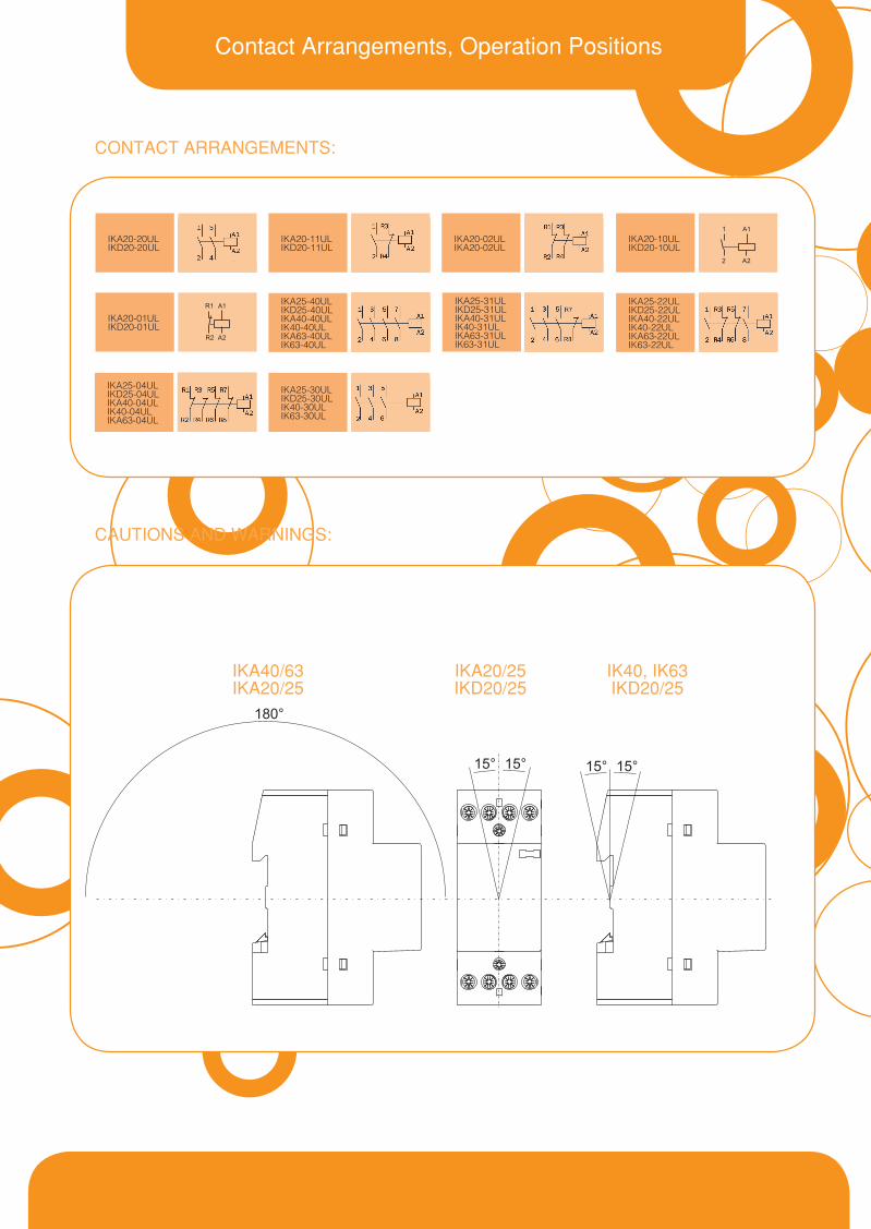
Contact Arrangements, Operation Positions
CONTACT ARRANGEMENTS:
CAUTIONS AND WARNINGS:
IKA20-10ULIKD20-10UL
IKA25-31ULIKD25-31ULIKA40-31ULIK40-31ULIKA63-31ULIK63-31UL
IKA25-04ULIKD25-04ULIKA40-04ULIK40-04ULIKA63-04UL
IKA25-22ULIKD25-22ULIKA40-22ULIK40-22ULIKA63-22ULIK63-22UL
IKA20-01ULIKD20-01UL
IKA20-20ULIKD20-20UL
IKA20-11ULIKD20-11UL
IKA20-02ULIKA20-02UL
IKA25-30ULIKD25-30ULIK40-30ULIK63-30UL
IKA25-40ULIKD25-40ULIKA40-40ULIK40-40ULIKA63-40ULIK63-40UL
IKA20/25IKD20/25
IK40, IK63IKD20/25
IKA40/63IKA20/25
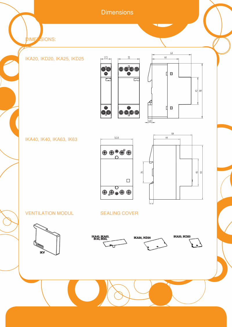
DIMENSIONS:
IKA20, IKD20, IKA25, IKD25
IKA40, IK40, IKA63, IK63
VENTILATION MODUL SEALING COVER
Dimensions
IKA25, IKD25 IKA20, IKD20IKA40, IKA63, IK40, IK63,

Ordering Data
Auxiliary Switch IKN
IKA63- 40UL/230V Controlvoltage
UL/CSAapprovedVersionofcontactsType
DC Link Capacitors
Auxiliary Switch IKN
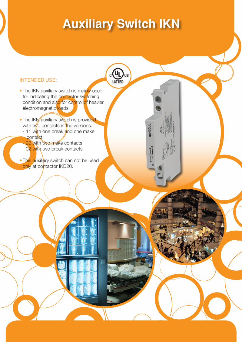
INTENDED USE:
•TheIKNauxiliaryswitchismainlyused forindicatingthecontactorswitching conditionandalsoforcontrolofheavier electromagneticloads
•TheIKNauxiliaryswitchisprovided withtwocontactsintheversions: -11withonebreakandonemake contact -20withtwomakecontacts -02withtwobreakcontacts
•Thisauxiliaryswitchcannotbeused onlyatcontactorIKD20.
Published by Iskra MIS, d. d. • Version 2.0, March 2011 • design Nimbus d.o.o.
® Ljubljanskac.24a,SI-4000Kranj,SloveniaTel.:+38642372112,Fax:+38642372129E-mail:[email protected],www.iskra-mis.si
Tehnical Data, Contact Arrangements, Dimesions
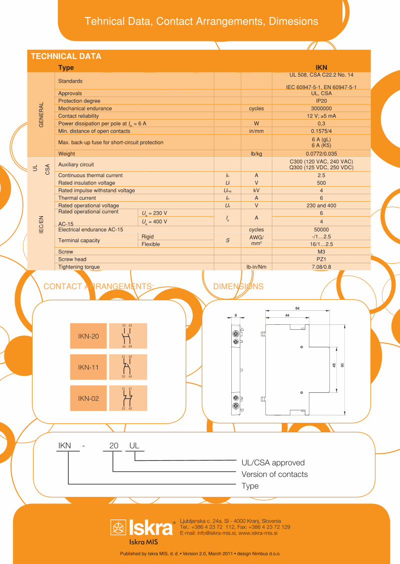
TECHNICAL DATAType IKN
GE
NE
RA
L
StandardsUL 508, CSA C22.2 No. 14
IEC 60947-5-1, EN 60947-5-1Approvals UL, CSAProtection degree IP20Mechanical endurance cycles 3000000Contact reliability 12 V; ≥5 mAPower dissipation per pole at Ith = 6 A W 0,3Min. distance of open contacts in/mm 0.1575/4
Max. back-up fuse for short-circuit protection 6 A (gL) 6 A (K5)
Weight lb/kg 0.0772/0.035
UL
CS
A Auxiliary circuit C300 (120 VAC, 240 VAC) q300 (125 VDC, 250 VDC)
Continuous thermal current Ith A 2.5
IEC
/EN
Rated insulation voltage Ui V 500Rated impulse withstand voltage Uimp kV 4Thermal current Ith A 6Rated operational voltage Ue V 230 and 400Rated operational current
AC-15
Ue = 230 VIe A
6
Ue = 400 V 4
Electrical endurance AC-15 cycles 50000
Terminal capacityRigid
S AWG/mm2
-/1…2.5Flexible 16/1…2.5
Screw M3Screw head PZ1Tightening torque lb-in/Nm 7.08/0.8
CONTACT ARRANGEMENTS: DIMENSIONS
IKN-11
IKN-02
IKN-20
IKN-20UL
UL/CSAapprovedVersionofcontactsType