Embed Size (px)
Citation preview
W:\Structures Team\08 - Non Project\50 - Expansion joints on TLRN\04 - Inspection Manual\Documents\v01a\[Final] vol 2 v01a.docx 19/05/2011
Inspection guidance for bridge expansion joints
Part 2 – Inspector’s Practical Guide

Transport for London
Surface Transport Inspection guidance for bridge expansion joints
Part 2 – Inspector’s Practical Guide
2
Contents
0 Document control ........................................................................................................................................... 3
0.1 Author ................................................................................................................................................... 3
0.2 Document history .................................................................................................................................. 3
0.3 Acknowledgements ............................................................................................................................... 3
1 Introduction .................................................................................................................................................... 4
2 How to use part two ....................................................................................................................................... 4
3 On site checklist .............................................................................................................................................. 5
4 Classifying defects .......................................................................................................................................... 5
4.1 All joint types ........................................................................................................................................ 7
4.2 HA type 1: Buried joint ........................................................................................................................ 12
4.3 HA type 2: Asphaltic plug type ............................................................................................................ 15
4.4 HA types 3 and 4: Nosing joints .......................................................................................................... 17
4.5 HA type 5: Reinforced elastomeric ..................................................................................................... 18
4.6 HA type 6: Elastomeric in metal runners (cast-in and resin-encapsulated) ........................................ 21
4.7 HA type 6: Elastomeric in metal runners (resin encapsulated) ........................................................... 24
4.8 HA type 7: Cantilever tooth or comb joint .......................................................................................... 25
5 Emergency action plan ................................................................................................................................. 27
6 References .................................................................................................................................................... 27
Appendix 1 Defect categories table ...................................................................................................................... 28

Transport for London
Surface Transport Inspection guidance for bridge expansion joints
Part 2 – Inspector’s Practical Guide
3
0 Document control
0.1 Author
Peter Jones
0.2 Document history
Date Version Status Issued to
20/12/2010 00a Draft Nadia Kaddouri
22/12/2010 00b Draft Stephen Pottle, Steve Eggleton and Nadia Kaddouri
24/02/2011 00c Draft Stephen Pottle, Nadia Kaddouri
09/03/2011 00d Draft Stephen Pottle
08/04/2011 00e Draft Structures Management Team
18/05/2011 01a Final
0.3 Acknowledgements It should be recorded that the author is grateful to those working for and on behalf of Transport for London, Highways Agency and Transport Scotland who took the time to review a draft of this document and provide valuable feedback, including several photographs that are contained in this part of the document (and credited where appropriate).
Transport for London
Surface Transport Inspection guidance for bridge expansion joints
Part 2 – Inspector’s Practical Guide
4
1 Introduction Part one of this document provides a useful reference guide to bridge deck expansion joints. Part two is
intended to be an on-site handbook to aid inspectors to rate the severity and extent of defects to bridge
expansion joints in a consistent manner, and adequately report the defect(s).
The importance of this cannot be understated. Part one of this document includes case studies of what can
happen when expansion joints are allowed to deteriorate beyond the condition at which they should be
replaced. The information from inspections should be used to determine works programmes for future years,
so in order for joint works to take place at the appropriate time, the information from inspections must be
accurate.
2 How to use part two Part two is focussed on identifying the correct classification for expansion joint defects. While inspecting
bridge joints in accordance with the recommendations of part one of this document, part two is to be used to
classify any defects identified. Part two contains many photographs and descriptions that can be compared to
what the inspector can see. It has been assumed that the reader will already have read part one of this
document.
Part two of this document should be read and used in conjunction with the guidance provided in the following
publications:
CSS Bridge Condition Indicators volume 1 (1) and 2 (2) and associated addenda (3)
Inspection Manual for Highway Structures (4)
TfL structures inspection contract (where applicable)
BD63 Inspection of highway structures (5)
The table in Appendix one should be used in place of item number 10 in the table in Appendix C of the
Addendum to CSS Guidance Note on Bridge Condition Indicators (3) or in place of item number 10 in Table G10
of the Inspection Manual for Highway Structures (4).

Transport for London
Surface Transport Inspection guidance for bridge expansion joints
Part 2 – Inspector’s Practical Guide
5
3 On site checklist Various sections of part one provide guidance to inspectors on what to look for when inspecting expansion
joints and requirements for reporting the condition and defects of joints. It is important to consider the
requirements of an expansion joint when performing the inspection. These requirements can provide an aide-
memoire for inspection:
Joint performance check What should be looked at
Can the joint withstand traffic loading?
Joint, nosings - Movement under traffic loading - Noise under traffic loading
Does the joint accommodate movement?
Parapets, cover plates - Evidence of movement (may not be visible in summer when
bridge has expanded)
Does the joint offer good ride quality?
Joint, transition strip, resin strip, nosing material, adjacent surfacing (including on footway/verges/reserve) - Cracks, tracking, rutting, pot-holes, debonding, unacceptable
gaps, flow of binder, missing or loose plates
Does the joint offer sufficient skid/slip resistance?
Joint, transition strip, resin strip, nosing material, adjacent surfacing - Signs of wear, polished surfaces - Check carriageway, footways and cycle routes
Is there excessive noise/vibration? Joint - Listen from underneath (if possible) as traffic crosses joint
Is there potential for rapid deterioration?
Joint, transition strips, resin strips, nosing, adjacent surfacing - Cracks, tears, deformed components, any protruding
components, potential to form pot-holes - Debris located in seals
Is the joint watertight? Seals - Cracked, breached or missing Bond between joint/transition strip/resin strip/nosing/surfacing - Lack of bond
Is the joint suitably drained? Road drainage, sub-surface drainage - Flooding, saturated areas of carriageway, outlets, bearing shelf
drainage
Is the joint the same type throughout?
Visual check
Table 3.1 Requirements checklist
4 Classifying defects Definitions for the defect severity and extent codes can be read in part one of this document and in the BCI
commission report (6). This section seeks to add clarity to those definitions in the context of expansion joints,
as well as describing the defect types available..
Some of the defect codes are specific to a particular joint type, while others are relevant to several. The table
below lists the defect codes the inspector can select from, and indicates for which joint type they are relevant.

Transport for London
Surface Transport Inspection guidance for bridge expansion joints
Part 2 – Inspector’s Practical Guide
6
Def
ect
cod
e Defect description
HA
typ
e 1
Bu
ried
join
t
HA
typ
e 2
Asp
hal
tic
plu
g
HA
typ
e 3
/4
No
sin
g jo
int
HA
typ
e 5
Rei
nfo
rced
ela
sto
mer
ic
HA
typ
e 6
Elas
tom
eric
in m
etal
run
ner
s (
cast
-in
)
HA
typ
e 6
(res
in e
nca
psu
late
d)
HA
typ
e 7
Can
tile
ver
too
th o
r
com
b
17.1
All
join
t ty
pes
Joint leakage
17.2 Joint sub-surface drainage ×
17.3 Adjacent surfacing ×
17.4 Fixtures
17.5 Joint vegetation
17.6
T 1 Surfacing over buried joint × × × × × ×
17.7 Seal for induced cracking × × × × × ×
17.8
Typ
e 2
Bonding between APJ and road × × × × × ×
17.9 Loss of material from APJ × × × × × ×
17.10 Tracking and flow of APJ binder × × × × × ×
17.11
Typ
es 3
-7 Nosing or transition/resin strip × × × ×
17.12 Missing bolts × × × × ×
17.13 Seals × × × ×
17.14 Components × × × Table 4.1 Defect codes for expansion joints (adapted from Bridge Condition Indicators Volume 1 Commission Report (6))
Key: × = not applicable, = applicable, to be inspected (where present).
The tables in the following sections list the defect types, by each joint type, with comments for each severity
type and defect type, along with photographs to illustrate the descriptions.
The CSS description column of the tables contains the wording from the CSS defect table (3) The comment
column provides an interpretation of this description, in the context of the joint type.
Note: The majority of photographs in the following sections are from TfL inspection reports and site visits. The
occasional photograph has been taken from the Inspection Manual for Highway Structures, volume 2 (7). Since
the tables draw on TfL’s experience, the tables are not complete with relevant examples. As such, this section
should be considered as a “live” document and submissions of relevant examples will be gratefully received.
Key to tables:
guidance on reporting defect
advice on selecting the appropriate impact code

Transport for London
Surface Transport Inspection guidance for bridge expansion joints
Part 2 – Inspector’s Practical Guide
7
4.1 All joint types
7.1 Joint leakage. This may be difficult to detect if the weather is dry, and has been for a number of days. There still may be some staining, which would indicate past, but not necessarily current, leakage. If possible, assess the condition of the secondary membrane in the expansion gap. Detection of leakage is usually from below, so this defect has not been divided between different joint types. Reasons for leakage may be visible from surface level, and these should be recorded in the inspection report.
Seve
rity
CSS description Photograph Comment
1
No visible signs of leakage
(Courtesy of Transport Scotland)
Areas below the expansion joint show no sign of water or water stains.
2
Minor leakage through joint
Small amounts of water appear to be leaking from the expansion joint. There is no apparent damage to other parts of the structure.
3
Moderate leakage through joint
Noticeable volumes of water are passing through the joint, with a reasonable expectation that structural deterioration will be quicker as a result. Damage is occurring to protective systems, such as the paint system.
4
Major leakage through joint, causing structural damage
High volumes of water drain through the joint, causing some minor damage, including minor corrosion to bearings or bearing shelf.
5
Open joint causing major structural damage
The expansion joint is open and water is freely passing from the carriageway through the expansion gap. Corrosion is significant to either bearings, bearing shelf or abutment.
Joint leakage will be most obvious from below deck, though major problems will be obvious from above as well. The description must back up the severity indicated, for example, is it based on the presence of water or stains? Any damage occurring as a result of leakage should be described, including location, nature of damage and area of affected area (dimensions). Defects to any drainage systems should be recorded under the Drainage heading in the report, with a reference, where appropriate, to the effect on the expansion joint. It may not be possible to access the bearing or abutment shelf during a general inspection, but if possible it should be checked, even if from a distance, and any notable findings recorded.
The impact code will generally reflect the severity/extent combination. Where only a small amount of water is leaking, the impact may only be aesthetic, but where a significant amount of water is leaking, this will affect the durability of the structure. It is unlikely to be higher.

Transport for London
Surface Transport Inspection guidance for bridge expansion joints
Part 2 – Inspector’s Practical Guide
8
17.2 Condition of joint sub-surface drainage
Seve
rity
CSS description Photograph Comment
1 N/A – new category proposed by TfL.
Joint drainage appears to be functioning correctly. There are no signs of ponding adjacent to the expansion joint. Outlets for the drainage are clear.
2
(Courtesy of Transport Scotland)
The outlets to the drainage are slightly blocked, but there are only very minor signs of ponding on the carriageway by the expansion joint.
3
There are signs of ponding on the carriageway by the expansion joint, but they are not extensive. The outlets are partially blocked.
4
Surface water on the carriageway is significant. The drainage outlets are almost fully blocked (>75%).
5 Joint drainage is completely non-functional. Ponding is severe. The drainage outlets appear blocked.
It will be difficult, and often not possible to inspect sub-surface drainage. Records should be checked to locate the outlet and this should be checked. Evidence of failure of the sub-surface drainage will be visible on the carriageway in the form of ponding.
The impact will generally be on durability.

Transport for London
Surface Transport Inspection guidance for bridge expansion joints
Part 2 – Inspector’s Practical Guide
9
17.3 Condition of road surfacing adjacent to joint
Seve
rity
CSS description Photograph Comment
1 Sound
The road surfacing adjacent to the joint is in as-new condition, with no cracks, tracking or rutting.
2 Minor break up of road surface adjacent to joint
There is some cracking or break-up, but it is not affecting ride quality, or exposing any part of the joint. Cracks are narrow and shallow (maximum depth 25mm).
3 Moderate break up of road surface adjacent to joint
The road surface is significantly cracked, but there are no pot-holes, nor is any part of the joint exposed. Crack depth is not deeper than 50mm.
4 Major break up of road surface adjacent to joint
The cracking is such that pot-holes are expected to form shortly. The joint or nosing is becoming exposed. The depth of the cracking is less than the depth of the surfacing.
5 Joint failure due to deteriorated condition of adjacent road surface
The surfacing has disintegrated, exposing the nosing or joint component. There may be leakage. The disintegration is to the full depth of the surfacing.
Location and size of broken area (width, length across carriageway, depth) should be detailed. A sketch may be the best way of providing this information. Notes on whether and how the joint is being damaged should be made, or where potential for damage exists.
The impact score will depend on the circumstances on site. Generally the condition of the surfacing alone will not merit a score higher than 4.

Transport for London
Surface Transport Inspection guidance for bridge expansion joints
Part 2 – Inspector’s Practical Guide
10
17.4 Condition of fixtures. This category should cover accessories to the joint, such as cover plates. For reinforced elastomeric joints, this defect category includes defects to bolt seals or loose/missing cover plates.
Seve
rity
CSS description Photograph Comment
1 Sound
The fixtures are all in place, are in good condition and are securely attached.
2 Bolt sealer missing
The elastomeric caps on the bolts protect them from corrosion and vehicle impact, but they regularly come free. The extent rating should be used to indicate proportion missing.
3 Fixings loose
Fixtures are all still attached, but there is at least one example of a loose fixing, but this is not causing a failure or danger to road users.
4 Fixings missing, plates and angles loose
Fixtures are missing or loose, but are not causing failure of the joint or a danger to road users/pedestrians. In this example, the plate is bent, leaving a trip hazard at the edges.
5 Failure due to missing fixtures
Missing fixtures are causing a failure of the joint. Failure would either be causing a danger to road-users or causing a significantly accelerated deterioration of the structure.
Description should include location of defective fixture, and details of the defect. If loose the reason should be stated (loose or missing bolts, damaged support, etc). In the case of bolt seals, the number missing and total number should be recorded. Loose bolts, which hold the main joint component, should be reported as defect 10.7.
The impact will reflect the site conditions, considering how the defect affects the structure.

Transport for London
Surface Transport Inspection guidance for bridge expansion joints
Part 2 – Inspector’s Practical Guide
11
17.5 Vegetation in the joint
Seve
rity
CSS description Photograph Comment
1 N/A – new category proposed by TfL.
There is no vegetation growing from any part of the expansion joint, either in the carriageway, verge, reserve or from underneath.
2 Small amounts of vegetation are growing from the joint, and are causing no hazard or not affecting functionality.
3
Vegetation is growing from the joint, and accelerating deterioration of the joint.
4 It is considered that vegetation will not cause a defect of severity four or five.
5
The description should detail the amount of vegetation, type of vegetation, where it is growing from and what problems it is causing to the joint or the structure.
The impact will be most likely to be durability, while very small amounts of vegetation can probably be given a rating of aesthetic.

Transport for London
Surface Transport Inspection guidance for bridge expansion joints
Part 2 – Inspector’s Practical Guide
12
4.2 HA type 1: Buried joint
17.6 Surfacing over buried joint
Seve
rity
CSS description Example Comment
1 Reasonably sound
Presence of joint is not obvious from the road surface, except for the sealed saw-cut, if present. There are no defects to the carriageway surfacing or verges/ footways/ reserve over the joint.
2 Minor surface cracking
(Courtesy of Transport Scotland)
There are some cracks in the surfacing over the joint, but these cracks area very narrow and shallow (maximum depth 25mm).
3 Moderate surface cracking
Cracks are clearly visible, up to 5mm in width at the extreme. The depth of the cracks is less than 50mm.
4 Major surface cracking
(Courtesy of Transport Scotland)
Cracks are developing, up to 25mm in width at the extreme. The depth of the crack is less than the depth of the surfacing.
Transport for London
Surface Transport Inspection guidance for bridge expansion joints
Part 2 – Inspector’s Practical Guide
13
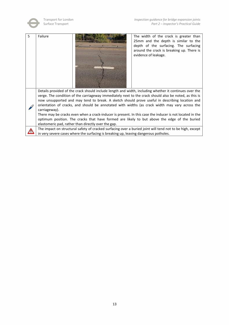
5 Failure
The width of the crack is greater than 25mm and the depth is similar to the depth of the surfacing. The surfacing around the crack is breaking up. There is evidence of leakage.
Details provided of the crack should include length and width, including whether it continues over the verge. The condition of the carriageway immediately next to the crack should also be noted, as this is now unsupported and may tend to break. A sketch should prove useful in describing location and orientation of cracks, and should be annotated with widths (as crack width may vary across the carriageway). There may be cracks even when a crack-inducer is present. In this case the inducer is not located in the optimum position. The cracks that have formed are likely to but above the edge of the buried elastomeric pad, rather than directly over the gap.
The impact on structural safety of cracked surfacing over a buried joint will tend not to be high, except in very severe cases where the surfacing is breaking up, leaving dangerous potholes.

Transport for London
Surface Transport Inspection guidance for bridge expansion joints
Part 2 – Inspector’s Practical Guide
14
17.7 Condition of sealant for induced cracking
Seve
rity
Description Photograph Comment
1 Sound
The sealant in the saw-cut is fully present, fully bonded to each side of the crack and is not raised above the carriageway surfacing level.
2 Minor cracking or break up of sealant for induced crack
The seal has some cracks, which are narrow and short and do not affect the integrity of the seal. The seal has not been pushed upwards to any noticeable degree.
3 Moderate cracking or break up of sealant for induced crack
The cracks are clearly visible, or some of the seal is unbonded. It is still generally functional. There is no evidence of leaking.
4 Major cracking or break up of sealant for induced crack
There is major cracking or break up of sealant, so it can no longer considered fully functional.
5 Disintegrated or missing sealant for induced crack
The seal is completely missing at some point causing break up of the adjacent but unsupported surfacing. There is evidence of water leakage.
The cracks and break up should be clearly described, including location. One reason for break up of the seal is it has been pushed up as the gap closes, and then broken off by traffic. Damage to the adjacent surfacing caused by defects to the saw-cut (unsupported surfacing once seal has disintegrated) should be recorded in defect category 10.7, with reference made to the lack of saw-cut seal as a cause.
The impact on structural safety of a defective seal is unlikely to be more than durability, as eventually it may lead to carriageway cracking.

Transport for London
Surface Transport Inspection guidance for bridge expansion joints
Part 2 – Inspector’s Practical Guide
15
4.3 HA type 2: Asphaltic plug type
17.8 Bonding between plug material and adjacent carriageway surfacing
Seve
rity
Description Photograph Comment
1 Sound
The plug/surfacing interface is bonded, with no gap evident, at any point across the carriageway, verge, reserve or footway.
2 Minor debonding between plug and road
The plug has debonded from the surfacing at some point across the carriageway, but the gap is still fairly narrow (1-2mm). The depth of the debonded area is maximum 25mm. The adjacent road surface remains in good condition.
3 Moderate debonding between plug and road
The debonded gap is now significant. The adjacent road surfacing is unsupported in the affected areas and has potential to start breaking up under traffic loading. The gaps is around 5mm wide and the depth is a maximum 50mm.
4 Major debonding between plug and road
The debonded gap is now greater, and there are visible signs of the adjacent surface breaking up because it is now clearly unsupported. The gap is greater than 5mm wide but the depth is less than that of the surfacing. There is some leakage evident.
5 Dangerous The joint is now sufficiently debonded that the adjacent surfacing is breaking up due to lack of unsupport. The plug material is also damaged as the leading edge is unprotected. The debonded area is to the full depth of the surfacing. The joint is leaking as a result.
The width, or range of widths of the gap should be provided, where along the joint this is occurring, and whether it is occurring at both sides of the joint, or just at one edge. Comment should also be made on the condition of the surfacing immediately adjacent to the debonded gap. The cause is generally due to construction details, but excessive movement may be the cause.
The impact on structural safety of this defect is generally low as it is unlikely to become safety critical, it will, however, if allowed to develop, affect the durability of the structure.

Transport for London
Surface Transport Inspection guidance for bridge expansion joints
Part 2 – Inspector’s Practical Guide
16
17.9 Loss of plug material
Seve
rity
CSS description Photograph Comment
1 Sound
Plug is 100% intact with no material missing.
2 Slight loss of surface binder and aggregate
A small amount of material is missing, with shallow holes in the plug (<20mm penetration). There is very little effect on ride quality or noise produced.
3 Loss of aggregate (surface penetration 20 to 50mm)
There is significant loss of material, with penetration up to 50mm. Ride quality is affected, and noise is produced.
4 Loss of material from joint (causing holes >50mm deep)
(Courtesy of Transport Scotland)
There is serious loss of material, with holes greater than 50mm in depth. There is some leakage evident.
5 Missing Some of the joint is missing to the full depth of the plug, or the plug is broken up as a result of missing material. The joint is leaking.
The description should describe the location of each area of missing material, size (approx width and length, or diameter, where appropriate) and depth of hole. A sketch may be the easiest way of clearly representing this information.
The impact will generally be low, but where the loss of material is severe, it could be a safety issue due to drivers taking avoiding action or damage to low clearance vehicles.

Transport for London
Surface Transport Inspection guidance for bridge expansion joints
Part 2 – Inspector’s Practical Guide
17
17.10 Tracking of plug material and flow of material onto adjacent surfacing
Seve
rity
Description Photograph Comment
1 Sound The plug follows the alignment of the adjacent surfacing, which is untracked, with no flow of plug material onto it.
2 Minor tracking and flow of binder
(Courtesy of Transport Scotland)
Slight depressions in the plug are visible on inspection, but are not significant, or some plug material has flowed beyond the boundary. The effect is purely aesthetic.
3 Moderate tracking and flow of binder
Tracking is clearly visible or a significant amount of binder has flowed onto the adjacent surfacing. Where tracking has occurred, there are small mounds of displaced material at the edges of the carriageway.
4 Major tracking and flow of binder
(Courtesy of Transport Scotland)
A very large amount of binder has flowed, or tracking is serious, generating significant mounds at the edges of the carriageway.
5 Disintegrated The tracking has occurred to such an extent that the joint is disintegrated. The joint is leaking.
The nature of the tracking should be described, including depth of tracks and which lanes it is affecting. A comment on the traffic density and speed may be relevant in suggesting the cause. Where binder has flowed beyond the joint boundary, again location should be given, and a measurement of spread. This information may be best represented on a sketch.
The impact of this defect is generally low. Only in the case of serious disintegration would an impact score greater than three be necessary.
4.4 HA types 3 and 4: Nosing joints There are very few of this type of joint on the TLRN, and so experience of these joints is limited. It is currently
unlikely that their number will increase due to the increased prominence of asphaltic plug type joints.
Transport for London
Surface Transport Inspection guidance for bridge expansion joints
Part 2 – Inspector’s Practical Guide
18
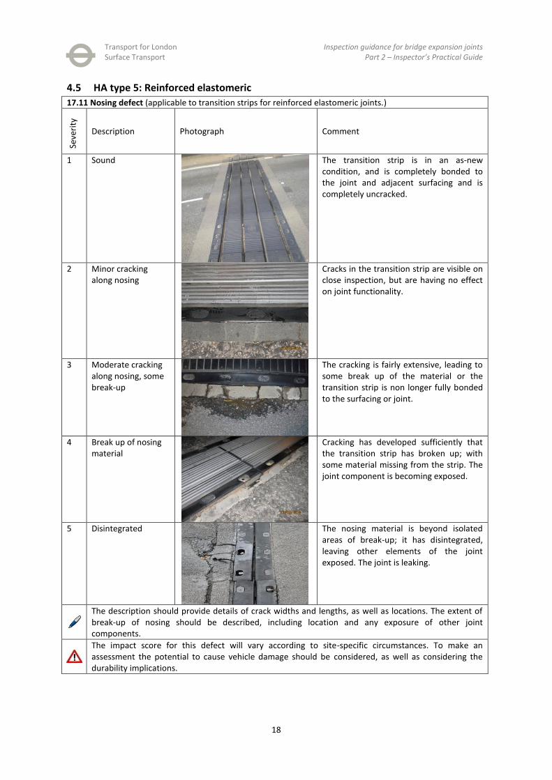
4.5 HA type 5: Reinforced elastomeric
17.11 Nosing defect (applicable to transition strips for reinforced elastomeric joints.)
Seve
rity
Description Photograph Comment
1 Sound
The transition strip is in an as-new condition, and is completely bonded to the joint and adjacent surfacing and is completely uncracked.
2 Minor cracking along nosing
Cracks in the transition strip are visible on close inspection, but are having no effect on joint functionality.
3 Moderate cracking along nosing, some break-up
The cracking is fairly extensive, leading to some break up of the material or the transition strip is non longer fully bonded to the surfacing or joint.
4 Break up of nosing material
Cracking has developed sufficiently that the transition strip has broken up; with some material missing from the strip. The joint component is becoming exposed.
5 Disintegrated
The nosing material is beyond isolated areas of break-up; it has disintegrated, leaving other elements of the joint exposed. The joint is leaking.
The description should provide details of crack widths and lengths, as well as locations. The extent of break-up of nosing should be described, including location and any exposure of other joint components.
The impact score for this defect will vary according to site-specific circumstances. To make an assessment the potential to cause vehicle damage should be considered, as well as considering the durability implications.

Transport for London
Surface Transport Inspection guidance for bridge expansion joints
Part 2 – Inspector’s Practical Guide
19
17.12 Missing bolts
Seve
rity
CSS description Photograph Comment
1 Minor signs of wear o o o o o o o o o o
o o o o o o o o o o
No bolts are missing. There are no more than minor signs of wear to the bolts.
2 One missing at cross section
o × o o o o o o o o
o o o o o o o o o o
A maximum of one bolt is missing at any cross section of the joint, and this one missing bolt is not causing failure.
3 Numerous bolts missing at cross section
o × o o o o o × o o o × o o o o o × o o
o o o × o o o o o o o o o × o o o o o o
More than one bolt is missing /loose and up to half are missing at a particular cross section. This severity class will only apply where there are more than two bolts at any cross section of the joint.
4 Majority of bolts missing at a cross section
o × o × o o o × o o
o × o × o o o × o o
At any particular cross section of the joint more than half of the bolts are missing/ loose, but this is not causing failure.
5 Failure due to missing bolts
o o o o o o o o o o
× × × × × o o o o o
The joint has failed due to loose/ missing bolts, regardless of how many are missing/ loose.
The description should give exact number of bolts missing from the total number on the joint. A sketch would be useful to identify which are missing (similar to those above). Information on whether the missing bolts are causing movement/noise under traffic loading should also be included, and whether it significant under all traffic, or only heavy vehicles. The extent category should be based on the number of cross sections across the joint at that particular severity class.
The impact score should take into account which bolts are missing, and whether the component is likely to start to lift. In this case, the impact should be scored at 4 or 5.

Transport for London
Surface Transport Inspection guidance for bridge expansion joints
Part 2 – Inspector’s Practical Guide
20
17.14 Condition of joint components. In the case of reinforced elastomeric joints “component” refers to the pre-manufactured unit.
Seve
rity
CSS description Photograph Comment
1 Sound
All joint components are in good condition, with no visible signs of defects. There are no cracks or tears visible.
2 Initiation of cracking or tearing of components
Cracks or tears are visible. They are hairline and will require careful inspection to detect.
3 Crack/tear <20% of width of component
Cracks and tears are easily visible but the joint is still able to function.
4 Crack/tear >20% by <50% of width of component
Cracks and tears are significant, but there remains some limited functionality. The steel in the plates is exposed. Complete failure can be expected shortly.
5 Failure of expansion joint component
A component of the joint has completely failed. Part of it has detached or is missing. A steel plate is loose or missing.
The location of the defective component should be clear, either through description or sketch. The cause of the defect should be explained or at least a possible reason suggested.
The impact of defects to the elastomeric component can be high, as highlighted in the first case study in part one of this document. This type of joint is known to be susceptible to sudden failure. Impact codes 4 and 5 should be considered where the defect is beyond the very early stages (say severity three or higher). This will ensure that remedial works are completed on time to prevent a failure.

Transport for London
Surface Transport Inspection guidance for bridge expansion joints
Part 2 – Inspector’s Practical Guide
21
4.6 HA type 6: Elastomeric in metal runners (cast-in and resin-encapsulated)
17.13 Condition of seals
Seve
rity
CSS description Photograph Comment
1 Strip sealant sound
(Courtesy of Transport Scotland)
The seal appears in good condition, with no breaches, cracks or tears. It is securely attached on both sides. No debris is present in the seal.
2 Strip sealant loose/poor, compression seal dropped and/or worn
(Courtesy of Transport Scotland)
The seal has some cracks, or very minor tears or breaches but is still able to function to a large extent. The defects require close attention to see. There is a small amount of debris in the seal.
3 Sealant breached, strip sealant breached
The seal is visibly breached, allowing some water through the joint. There is a small amount of debris in the seal.
4 Sealant missing, strip sealant missing/out
The seal is missing or significantly breached at least at some point across the joint. It does retain some limited functionality but there is evidence of water leakage. The seal is holding a significant amount of debris.

Transport for London
Surface Transport Inspection guidance for bridge expansion joints
Part 2 – Inspector’s Practical Guide
22
5 Failure
(Courtesy of Transport Scotland)
The seal is missing or sufficiently disintegrated to allow large amounts of water to flow through the joint. The seal is full of debris. (In the example to the left, the seal is completed detached from the metal rail on the right-hand side)
The nature of the defect should be described, with the locations of the breaches identified.
The impact will generally be durability, unless the defect is very minor, in which case aesthetic or no impact will be more appropriate.

Transport for London
Surface Transport Inspection guidance for bridge expansion joints
Part 2 – Inspector’s Practical Guide
23
17.14 Condition of components
Seve
rity
CSS description Photograph Comment
1 Sound
The rails are in good condition. They are straight, level and flush with the adjacent surfacing. There are no cracks in the rails.
2 Initiation of cracking or tearing of components.
The rails are generally in good condition but on close inspection there are very slight deformities, but no vertical deflection.
3 Crack/tear <20% of width of component
A rail is clearly deformed, but is still able to function safely. There is no vertical deflection of the rail.
4 Crack/tear >20% but <50% of width of component
There has been some limited vertical deflection of the rail, or there are short hairline cracks in the rail.
5 Failure of expansion joint components
A rail has completed cracked, is missing, has dropped due to failure of the supporting mechanism below or there has been significant upward deflection of the rail, which is now likely to be pulled up by passing vehicles.
Description should include location of defective fixing, and details of the defect. If loose the reason should be stated (loose or missing bolts, damaged support, etc). In the case of bolt seals, the number missing and total number should be recorded.
The impact will reflect the site conditions, and it is difficult to generalise. Whether the defect is likely to cause a danger should be considered.

Transport for London
Surface Transport Inspection guidance for bridge expansion joints
Part 2 – Inspector’s Practical Guide
24
4.7 HA type 6: Elastomeric in metal runners (resin encapsulated)
17.11 Resin strip defect
Seve
rity
CSS description Photograph Comment
1 Sound
The resin strip is in an as-new condition, is completely bonded to the joint and adjacent surfacing and is completely uncracked.
2 Minor cracking along nosing
Cracks are visible on close inspection, but there is no effect on joint functionality.
3 Moderate cracking along nosing, some break-up
Cracking of the strip is fairly extensive. Some functionality remains – the surfacing is generally unsupported and the rails are generally protected.
4 Break up of nosing material
(Courtesy of Transport Scotland)
Isolated areas of the resin have broken up, leaving parts of the rails unprotected and some of the adjacent surfacing unprotected.
5 Disintegrated
The resin has disintegrated sufficiently to exposed the reinforcement embedded in the resin, as well as leaving the rails unprotected. The joint is leaking.
The description should provide details of crack widths and lengths, as well as locations. The extent of break-up of resin should be described, including location and any exposure of other joint components.
The impact score for this defect will vary according to site-specific circumstances. To make an assessment, the potential to cause vehicle damage should be assessed, as well as considering the durability implications.

Transport for London
Surface Transport Inspection guidance for bridge expansion joints
Part 2 – Inspector’s Practical Guide
25
4.8 HA type 7: Cantilever tooth or comb joint
17.12 Missing bolts
Seve
rity
CSS description Photograph Comment
1 Minor signs of wear
No bolts are missing. There are no more than minor signs of wear to the bolts.
2 One missing at cross section
o × o o o o o o o o
o o o o o o o o o o
A maximum of one bolt is missing at any cross section of the joint, and this one missing bolt is not causing failure.
3 Numerous bolts missing at cross section
o × o o o o o × o o o × o o o o o × o o
o o o × o o o o o o o o o × o o o o o o
More than one bolt is missing /loose and up to half are missing at a particular cross section. This severity class will only apply where there are more than two bolts at any cross section of the joint.
4 Majority of bolts missing at a cross section
o × o o o o o × o o o × o × o o o × o o
o o o × o o o o o o o o o × o o o o o o
o × o × o o o × o o
o × o × o o o × o o
At any particular cross section of the joint more than half of the bolts are missing/ loose, but this is not causing failure.
5 Failure due to missing bolts
o o o o o o o o o o
× × × × × o o o o o
The joint has failed due to loose/ missing bolts, regardless of how many are missing/ loose.
The description should give exact number of bolts missing from the total number on the joint. A sketch would be useful to identify which are missing (similar to those above). Information on whether the missing bolts are causing movement/noise under traffic loading should also be included, and whether it significant under all traffic, or only heavy vehicles.
The impact score should take into account which bolts are missing, and whether the component is likely to start to lift. In this case, the impact should be scored at 4 or 5.

Transport for London
Surface Transport Inspection guidance for bridge expansion joints
Part 2 – Inspector’s Practical Guide
26
17.14 Condition of joint components. Components for this type of joint are usually pre-cast steel units, bolted to the bridge deck/abutment.
Seve
rity
CSS description Photograph Comment
1 Sound
All comb components are in good condition, with no corrosion or cracks. There is no deformation of teeth.
2 Initiation of cracking or tearing of components
The teeth are showing minor signs of corrosion, but no cracks are visible. Any loss of section is unidentifiable and there is no deformation of any teeth.
3 Crack/tear <20% of width of component
The teeth are moderately corroded with very minor loss of section (<5%). There is no limitation of movement and there are no signs of cracks or deformation of the teeth.
4 Crack/tear >20% by <50% of width of component
The teeth are severely corroded with significant loss of section (<20%) or there is some deformation of the teeth, but not to the extent where movement is restrained or traffic will be affected.
5 Failure of expansion joint component
At least one tooth has fractured, or the teeth are sufficiently misaligned so that movement will cause interference, or there is a crack in the metalwork. Corrosion has caused a serious loss of section of a tooth (>20%).
The location of the defective component should be clear, either through description or sketch. The cause of the defect should be explained or at least a possible reason suggested.
The impact will reflect the site conditions, and it is difficult to generalise. Where a defect is the beginnings of a broken tooth, or similar, serious defect, a higher impact rating should be considered.

Transport for London
Surface Transport Inspection guidance for bridge expansion joints
Part 2 – Inspector’s Practical Guide
27
5 Emergency action plan In the case that the inspector identifies a defect which is likely to either cause a danger to the public or the
structure, or will cause significant deterioration before the report is reviewed by TfL, the inspector has a duty
to inform TfL by alternative means so that the defect can be attended to.
6 References 1. Atkins. Bridge condition indicators volume 1 - Commission report. Lincoln, UK : CSS, 2002.
2. —. Bridge condition indicators volume 2 - Guidance notes on bridge inspection reporting. Lincoln, UK : CSS,
2002.
3. —. Addendum to Bridge condition indicators volume 2 - Guidance notes on bridge inspection reporting.
Lincoln, UK : CSS, 2004.
4. Highways Agency. Inspection Manual for Highway Structures. London, UK : The Stationery Office, 2007.
5. —. BD63/07 Inspection of Highway Structures. London, UK : The Stationery Office, 2007.
6. Atkins. Bridge condition indicators volume 1 - Commission report. Lincoln, UK : CSS, 2002.
7. Highways Agency. Inspection Manual for Highway Structures, volume 2. London, UK : The Stationery Office,
2007.

Transport for London
Surface Transport Inspection guidance for bridge expansion joints
Part 2 – Inspector’s Practical Guide
28
Appendix 1 Defect categories table This table should be used in place of defect category 10 in the existing table in Appendix C of the Addendum to Bridge Condition Indicators volume 2.
Severity
1 2 3 4 5
All joint types
17 1 Joint leakage The area below the expansion joint shows no sign of water or water staining. This includes the underside of the deck, the bearing shelf and the abutment wall.
Small amounts of water appear to be leaking from the expansion joint. There is no apparent damage to other parts of the structure.
Noticeable volumes of water are passing through the expansion joint, and there is now a reasonable expectation that durability of the structure will be affected. Damage is occurring to protective systems such as the paint system.
High volumes of water are draining through the expansion joint, causing some minor structural damage, including minor corrosion to the bearings or bearing shelf.
The expansion joint is open and water is freely passing from the carriageway through the expansion gap. Corrosion is significant to the bearings, bearing shelf or abutment.
2 Joint sub-surface drainage
Joint drainage appears to be functioning correctly. There are no signs of ponding adjacent to the expansion joint. Outlets for the drainage are clear.
The outlets to the drainage are slightly blocked, but there is no obvious sign of ponding on the carriageway by the expansion joint.
There are signs of ponding on the carriageway by the expansion joint, but they are not extensive. The outlets are partially blocked.
Surface water on the carriageway is significant. The drainage outlets are almost fully blocked (>75%).
Joint drainage is completely non-functional. Ponding is severe. The drainage outlets appear blocked.
3 Adjacent road surfacing
The road surfacing adjacent to the joint is in as-new condition, with no cracks, tracking or rutting.
There is some cracking, but this is not affecting the ride quality, or exposing any part of the joint.
The road surfacing is significantly cracked, but there are no pot-holes, nor is any part of the joint exposed.
The cracking is such that pot-holes are expected to form shortly. The joint or nosing is becoming exposed.
The surfacing has disintegrated, exposing the nosing or the joint component. There may be leakage.
4 Fixtures All plates and cover plates are in good condition, securely attached.
A plate is slightly defective, either bent or loose, but it is not causing any loss of functionality or a hazard.
A plate is significantly loose or heavily damaged, but is generally functional and is not causing a hazard.
A plate is missing, but not causing a significant hazard, but may affect durability in the long term.
A plate is missing or sufficiently loose to cause a significant hazard.
5 Joint vegetation There is no vegetation growing from any part of the expansion joint, either in the carriageway, verge, reserve or from underneath.
Small, insignificant amount of vegetation are growing from the joint, and are causing no hazard or not affecting functionality.
Small amounts of vegetation are growing from the joint, and are causing a limited inconvenience, for example to pedestrians.
Vegetation is present in the joint and is fairly widespread, causing inconvenience and reduced durability of the joint.
There is a significant amount of vegetation growing from the expansion joint, causing corrosion to the joint.

Transport for London
Surface Transport Inspection guidance for bridge expansion joints
Part 2 – Inspector’s Practical Guide
29
Buried joint
6 Surfacing over buried joint
The presence of the joint is not obvious from the surface (except for the sealed saw-cut, if present). There are no defects to the carriageway surfacing or verges/ footways /reserve over the joint.
There are some cracks in the surfacing over the joint, but these cracks are very narrow and shallow (max depth 25mm).
The cracks are clearly visible, up to but not exceeding 5mm in width at the extreme. The depth of the crack is less than 50mm. There is no evidence of water leakage.
Cracks have developed, up to 25mm in width at the extreme. The depth of the crack is less than the depth of the surfacing.
The width of the crack is greater than 25mm and the depth is similar to the depth of the surfacing. The surfacing around the cracks is breaking up. There is evidence of leakage.
7 Crack inducer sealant
The sealant in the saw-cut is fully present, fully bonded to each side of the crack and is not raised above the surfacing level.
The seal has some cracks, which are hairline and short, and do not affect the integrity of the seal. The seal has not been pushed upwards to any noticeable degree.
The cracks are clearly visible, or some of the seal is unbonded. Generally, it is still functional.
There is major cracking of break up of the sealant, so it can no longer be considered fully functional.
The seal is completely missing at some point, causing break up of the adjacent but unsupported surfacing.
Asphaltic plug joint
8 Plug debonding The plug/ surfacing interface is bonded, with no gap evident, at any point across the carriageway, verge, reserve or footway.
The plug has debonded from the surfacing at some point across the carriageway, but the gap is still narrow (1-2mm). The depth of the debonded area is maximum 25mm. The adjacent road surface remains in good condition.
The debonded gap is now significant. The adjacent road surfacing is unsupported in the affected areas and has potential to start breaking up under traffic loading. The gap is around 5mm wide and the depth is less than 50mm.
The debonded gap is now greater, there are visible signs of the adjacent surface breaking up because it is now clearly unsupported. The gap is greater than 5mm wide but the depth is less than the depth of the surfacing. There is some leakage evident.
The joint is now sufficiently debonded that the adjacent surfacing is breaking up due to lack of support. The plug material is also damaged as the leading edge is unprotected. The debonded area is to the full depth of the surfacing. The joint is leaking as a result.
9 Loss of plug material
The plug is 100% intact, with no missing material.
A small amount of material is missing, with shallow holes in the plug (<20mm penetration). There is very little effect on ride quality or very little noise produced.
There is significant loss of material, with penetration up to 50mm. Ride quality is affected and noise is produced.
There is a serious loss of material, with holes deeper than 50mm. There is some leakage evident.
Some of the joint is missing to the full depth of the plug, or the plug is broken up as a result of missing material. The joint is leaking.

Transport for London
Surface Transport Inspection guidance for bridge expansion joints
Part 2 – Inspector’s Practical Guide
30
10 Tracking and flow of material
The plug follows the alignment of the adjacent surfacing, which is untracked, with no flow of plug material onto it.
Slight depressions in the plug are visible on inspection, but are not significant, or some plug material has flowed beyond the boundary. The effect is purely aesthetic.
Tracking is clearly visible or a significant amount of binder has flowed onto the adjacent surfacing. Where tracking has occurred, there are small mounds of displaced material at the edges of the carriageway.
A very large amount of binder has flowed, or tracking is serious, generating significant mounds at the edges of the carriageway.
The tracking or flow of material has occurred to such an extent that the joint has disintegrated. The joint is leaking.
All other joint types
11 Nosing defects Reinforced elastomeric
The transition strip is in an as-new condition, and is completely bonded to the joint and adjacent surfacing and is completely uncracked.
Cracks in the transition strip are visible on close inspection, but are having no effect on joint functionality.
The cracking is extensive, leading to some break up of the material or the transition strip is no longer fully bonded to the surfacing or joint.
Cracking has developed sufficiently that the transition strip has broken up, with some material missing from the strip. The joint component is becoming exposed.
The nosing material is beyond isolated break up – it has disintegrated, leaving other elements of the joint exposed. The joint is leaking.
Elastomeric in metal runners (resin-encapsulated)
The resin strip is in as new-condition (see above).
Cracks are visible on close inspection, but there is no effect on joint functionality.
Cracking of the strip is fairly extensive. Some functionality remains – the surfacing is generally supported and the rails are generally protected.
Isolated areas of the resin have broken up, leaving parts of the rails unprotected and some of the adjacent surfacing unsupported.
The resin has disintegrated sufficiently to expose the reinforcement embedded in the resin, as well as leaving the rails and adjacent surfacing unprotected. The joint is leaking.
12 Missing or loose bolts
No bolts are missing or loose. There is no more than minor wear to the bolts.
A maximum of one bolt is missing/loose at any cross section of the joint, and this one missing bolt is not causing failure.
More than one bolt is missing/loose and up to half are missing/loose at a particular cross section. This severity class will only apply where there are more than two bolts at any cross section of the joint.
At any particular cross section of the joint, more than half of the bolts are missing/loose, but this is not causing failure.
The joint has failed due to missing/loose bolts, regardless of how many are missing/loose.
Transport for London
Surface Transport Inspection guidance for bridge expansion joints
Part 2 – Inspector’s Practical Guide
31
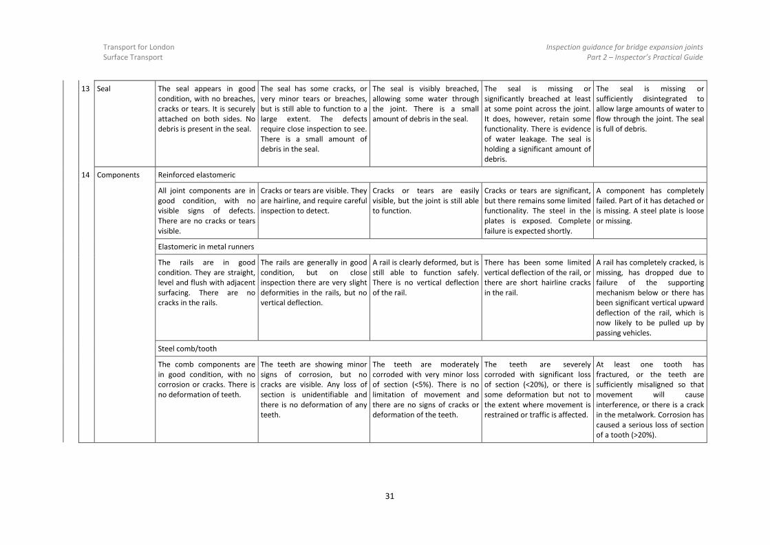
13 Seal The seal appears in good condition, with no breaches, cracks or tears. It is securely attached on both sides. No debris is present in the seal.
The seal has some cracks, or very minor tears or breaches, but is still able to function to a large extent. The defects require close inspection to see. There is a small amount of debris in the seal.
The seal is visibly breached, allowing some water through the joint. There is a small amount of debris in the seal.
The seal is missing or significantly breached at least at some point across the joint. It does, however, retain some functionality. There is evidence of water leakage. The seal is holding a significant amount of debris.
The seal is missing or sufficiently disintegrated to allow large amounts of water to flow through the joint. The seal is full of debris.
14 Components Reinforced elastomeric
All joint components are in good condition, with no visible signs of defects. There are no cracks or tears visible.
Cracks or tears are visible. They are hairline, and require careful inspection to detect.
Cracks or tears are easily visible, but the joint is still able to function.
Cracks or tears are significant, but there remains some limited functionality. The steel in the plates is exposed. Complete failure is expected shortly.
A component has completely failed. Part of it has detached or is missing. A steel plate is loose or missing.
Elastomeric in metal runners
The rails are in good condition. They are straight, level and flush with adjacent surfacing. There are no cracks in the rails.
The rails are generally in good condition, but on close inspection there are very slight deformities in the rails, but no vertical deflection.
A rail is clearly deformed, but is still able to function safely. There is no vertical deflection of the rail.
There has been some limited vertical deflection of the rail, or there are short hairline cracks in the rail.
A rail has completely cracked, is missing, has dropped due to failure of the supporting mechanism below or there has been significant vertical upward deflection of the rail, which is now likely to be pulled up by passing vehicles.
Steel comb/tooth
The comb components are in good condition, with no corrosion or cracks. There is no deformation of teeth.
The teeth are showing minor signs of corrosion, but no cracks are visible. Any loss of section is unidentifiable and there is no deformation of any teeth.
The teeth are moderately corroded with very minor loss of section (<5%). There is no limitation of movement and there are no signs of cracks or deformation of the teeth.
The teeth are severely corroded with significant loss of section (<20%), or there is some deformation but not to the extent where movement is restrained or traffic is affected.
At least one tooth has fractured, or the teeth are sufficiently misaligned so that movement will cause interference, or there is a crack in the metalwork. Corrosion has caused a serious loss of section of a tooth (>20%).

Transport for London
Surface Transport Inspection guidance for bridge expansion joints
Part 2 – Inspector’s Practical Guide
32
18 1 Movement/ construction joints
Seal is well bonded, uncracked, non-protruding and fully present along the whole length of the joint.
Seal is slightly unbonded, slightly cracked, or has been slightly pushed out, but retains a significant amount of functionality.
Breaches in the seal are clearly evident, but there remains a degree of functionality.
There are significant breaches in the seal, or the seal is missing over a relatively short length, meaning it retains some functionality.
Seal is missing over such a length to mean the joint is non-functional.