Embed Size (px)
Citation preview
Innovative Circuit Simulation and Analysis
Xpedition AMS
w w w . m e n t o r . c o m / x x x x x x x x x x
D A T A S H E E T
PCB Design
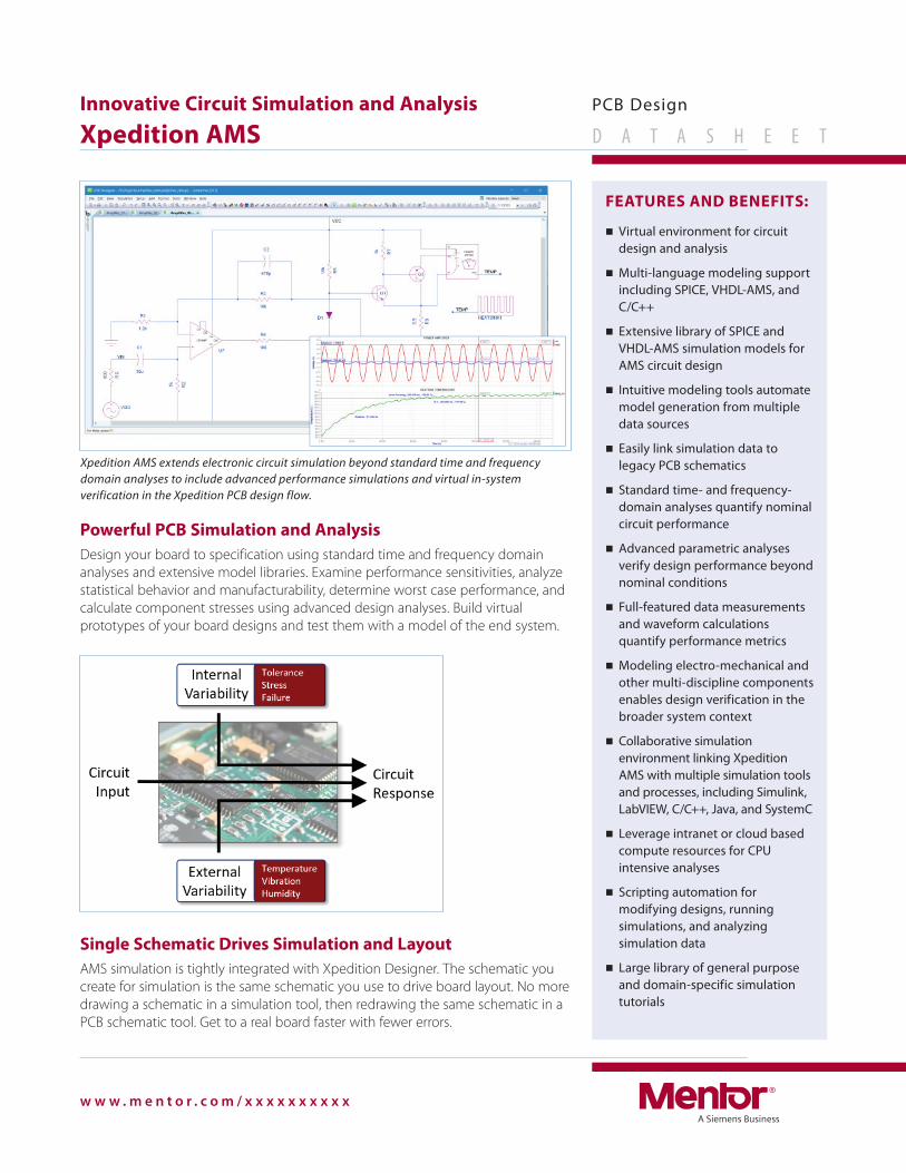
Powerful PCB Simulation and Analysis
Design your board to specification using standard time and frequency domain
analyses and extensive model libraries. Examine performance sensitivities, analyze
statistical behavior and manufacturability, determine worst case performance, and
calculate component stresses using advanced design analyses. Build virtual
prototypes of your board designs and test them with a model of the end system.
Single Schematic Drives Simulation and Layout
AMS simulation is tightly integrated with Xpedition Designer. The schematic you
create for simulation is the same schematic you use to drive board layout. No more
drawing a schematic in a simulation tool, then redrawing the same schematic in a
PCB schematic tool. Get to a real board faster with fewer errors.
FEATURES AND BENEFITS:
■ Virtual environment for circuit design and analysis
■ Multi-language modeling support including SPICE, VHDL-AMS, and C/C++
■ Extensive library of SPICE and VHDL-AMS simulation models for AMS circuit design
■ Intuitive modeling tools automate model generation from multiple data sources
■ Easily link simulation data to legacy PCB schematics
■ Standard time- and frequency-domain analyses quantify nominal circuit performance
■ Advanced parametric analyses verify design performance beyond nominal conditions
■ Full-featured data measurements and waveform calculations quantify performance metrics
■ Modeling electro-mechanical and other multi-discipline components enables design verification in the broader system context
■ Collaborative simulation environment linking Xpedition AMS with multiple simulation tools and processes, including Simulink, LabVIEW, C/C++, Java, and SystemC
■ Leverage intranet or cloud based compute resources for CPU intensive analyses
■ Scripting automation for modifying designs, running simulations, and analyzing simulation data
■ Large library of general purpose and domain-specific simulation tutorials
Xpedition AMS extends electronic circuit simulation beyond standard time and frequency domain analyses to include advanced performance simulations and virtual in-system verification in the Xpedition PCB design flow.

w w w . m e n t o r . c o m / x x x x x x x x x x
2
Simulate Legacy Designs
Every electronics design company has them – legacy schematics that need updating to meet new requirements or revisions,
but have no simulation data. Setting up legacy schematics for simulation requires linking simulation models to schematic
symbols. Xpedition automates this process, using an intuitive setup wizard, to quickly prepare even the most complex designs
for simulation.
SPICE (+ PSpice) Model Support
SPICE models are widely available for a variety of electronic components. Many of these models are in the popular PSpice format.
Xpedition supports standard SPICE models directly, and PSpice models through a fast and simple conversion process. Use SPICE
models from the large installed library, or download vendor models and use them in your projects.
Beyond SPICE Modeling
with VHDL-AMS
Beyond standard SPICE modeling, the IEEE
standard VHDL-AMS modeling language is
supported for added flexibility in modeling and
analyzing component and design behavior. VHDL-
AMS supports analog and event-driven behavior
for modeling and analyzing analog, digital, and
mixed-signal designs. The language goes beyond
the electrical domain into other design
technologies so you can model your circuit’s
target system, then do in-system verification using
virtual prototypes. And because VHDL-AMS is an
IEEE standard, you can share your models with
design teams using other tools.
Models Direct from Datasheets
A datasheet curve modeler extracts device data from performance curves, then uses the data to create a piecewise linear
model of the component. Easily generate models from any curve you can display on your computer monitor, or draw your
own graphs to create custom model functions. Datasheet performance tables are turned into a simulation model. Its simple
user interface looks like a datasheet table, so it’s easy to transfer information from a datasheet to the tool. Along with nominal
values, you can enter minimum and maximum values to create advanced models supporting statistical analyses.
Comprehensive
Stress Analysis
Component stress levels are
measureable from the moment power is
applied to a circuit. The stress level may
be high or low, and circuit reliability and
robustness are dependent on how well
these stresses are understood and
managed. Stress information can be
calculated for any performance metric,
and measurements are reported in
Microsoft Excel as a percent of rated
value for viewing, analysis, and derating
to help you understand your circuit’s
stress profile.
w w w . m e n t o r . c o m / x x x x x x x x x x
3
Worst-Case Scenario Exploration
A standard worst-case analysis reports valuable design performance information, but is often limited to parameter
dependencies built into the design. A worst case explorer considers built-in parameters, but also lets you define and control
special effects such as high and low thermal exposure and aging. These special effects are toggled on and off with user-
defined parameters, and can be combined to create custom worst-case scenarios. The explorer runs each scenario with the
defined parameter set, uses the selected measurements to quantify circuit performance, then reports the results in Microsoft®
Excel® for evaluation and analysis.
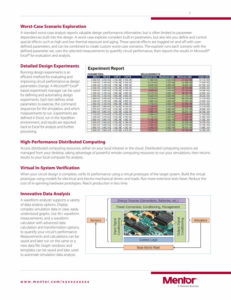
Detailed Design Experiments
Running design experiments is an
efficient method for evaluating and
improving circuit performance as design
parameters change. A Microsoft® Excel®
based experiment manager can be used
for defining and automating design
experiments. Each test defines what
parameters to exercise, the command
sequences for the simulation, and which
measurements to run. Experiments are
defined in Excel, run in the Xpedition
environment, and results are reported
back to Excel for analysis and further
processing.
High-Performance Distributed Computing
Access distributed computing resources, either on your local intranet or the cloud. Distributed computing sessions are
managed from your desktop, taking advantage of powerful remote computing resources to run your simulations, then returns
results to your local computer for analysis.
Virtual In-System Verification
When your circuit design is complete, verify its performance using a virtual prototype of the target system. Build the virtual
prototype using models for electrical and electro-mechanical drivers and loads. Run more extensive tests faster. Reduce the
cost of re-spinning hardware prototypes. Reach production in less time.
Innovative Data Analysis
A waveform analyzer supports a variety
of data analysis options. Display
complex simulation data in clear, easily
understood graphs. Use 45+ waveform
measurements, and a waveform
calculator with advanced data
calculation and transformation options,
to quantify your circuit’s performance.
Measurements and calculations can be
saved and later run on the same or a
new data file. Graph windows and
templates can be saved and later used
to automate simulation data analysis.
©2017 Mentor Graphics Corporation, all rights reserved. This document contains information that is proprietary to Mentor Graphics Corporation and may be duplicated in whole or in part by the original recipient for internal business purposes only, provided that this entire notice appears in all copies. In accepting this document, the recipient agrees to make every reasonable effort to prevent unauthorized use of this information. All trademarks mentioned in this document are the trademarks of their respective owners.
For the latest product information, call us or visit:
MGC 09-17 1034790-w
w w w . m e n t o r . c o m
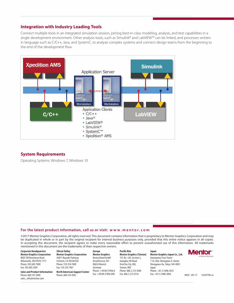
Integration with Industry Leading Tools
Connect multiple tools in an integrated simulation session, joining best-in-class modeling, analysis, and test capabilities in a
single development environment. Other analysis tools, such as Simulink® and LabVIEW™ can be linked, and processes written
in language such as C/C++, Java, and SystemC, to analyze complex systems and connect design teams from the beginning to
the end of the development flow.
System Requirements
Operating Systems: Windows 7, Windows 10