Embed Size (px)
DESCRIPTION
Infrared Thermos Canning Sample
Citation preview
All right reserved
INFRARED THERMOGRAPHY INSPECTION SERVICESREPORT OF SQUARE D BUSWAY SYSTEM
At
For
SCHNEIDER ELECTRIC (Hong Kong) LIMITED
ABC PROPERTY MANAGEMENT
ABC PLAZA
PRJXXXXX Report Print Date
(Client)
All right reserved
INFRARED THERMOGRAPHY INSPECTION SERVICESREPORT OF SQUARE D BUSWAY SYSTEM
COPYRIGHT, DISCLAIMER, PRIVACY POLICY AND FURTHER INFORMATION
EXECUTIVE SUMMARY
Section 1 SCOPE OF WORK
Section 2 REFERENCED STANDARDS
Section 3 GENERAL CONCEPT AND PRINCIPLES
Section 4 INSPECTION METHODOLOGY
Section 5 INSPECTION CONDITIONS
Section 6 INSPECTION RESULTS ANALYSIS
Section 7 CONCLUSION AND RECOMMENDATION
TABLE OF CONTENTS
2/16

All right reserved
INFRARED THERMOGRAPHY INSPECTION SERVICESREPORT OF SQUARE D BUSWAY SYSTEM
COPYRIGHT, DISCLAIMER, PRIVACY POLICY AND FURTHER INFORMATION
CopyrightCopyright restrictions apply to individual documents on this Report. Unless otherwise stated, the following copyright statement applies to documents found on this Report.
DisclaimerRETAIN FOR USE OF QUALIFIED MAINTENANCE PERSONNEL ONLY.
Schneider Electric (Hong Kong) Limited will only provide the infrared thermographic scanning inspection service according to the in-housed infrared thermographic survey procedure. The analysis report is only for internal reference of the client. Schneider Electric (Hong Kong) Limited will not be responsible for any legal duty and responsibility so caused by the analysis report. The client accepts full responsibility for any legal duty.
The total liability of Schneider Electric (Hong Kong) Limited under this contract agreement shall be limited to the inspection area where infrared thermographic scanning took place. Except as set out herein, Schneider Electric (Hong Kong) Limited shall be under no liability whatsoever to the Client for any loss, expense or damage howsoever caused, whether in contract or in tort or pursuant or any Statute, Rule or Regulation of otherwise, and whether such loss, expense or damage resulted from any act or omission or advice, including any negligent act or omission or advice given by Schneider Electric (Hong Kong) Limited.
Privacy PolicyWe have duty to protect any information we collect from you. We do not pass on your details to any third party unless you give us permission to do so.
3/16
All right reserved
INFRARED THERMOGRAPHY INSPECTION SERVICESREPORT OF SQUARE D BUSWAY SYSTEM
COPYRIGHT, DISCLAIMER, PRIVACY POLICY AND FURTHER INFORMATION
Further InformationPlease address any comments or questions you may have on the contact call or text to:
Project & Services DepartmentSCHNEIDER ELECTRIC (Hong Kong) Limited
Rooms, 3108-3128, 31/F., Sun Hung Kai Centre,30 Harbour Road, Wanchai, Hong Kong.G.P.O. Box 3125 H.K.Tel. (852) 2565 0621Fax (852) 2811 1029, (852) 2563 5414Hotline (852) 2579 9699Web page: http://www.scheider-electric.com.hk
4/16

All right reserved
INFRARED THERMOGRAPHY INSPECTION SERVICESREPORT OF SQUARE D BUSWAY SYSTEM
EXECUTIVE SUMMARY
In general results of inspected locations where incorporated at this report were commented at Normal Condition.
In addition to above classification, there are only TWO anomalies location finding which are described as Indicate Deficiency and stated below in briefly, and have detail analysis within the report.
Delta-TClassification
Action Required (Recommendation) Category
0°C to 3°C Warrant Investigation Indicate Possible Deficiency.
4°C to 15°C Repairs should be made as time permits
Indicate Deficiency
16°C and above Repairs should be made immdediately Indicate Major Deficiency
Busway Code Ampere Rating (A) Description LocationB4 3000 Tenant G/F to 18/F
Location 1 (anomaly):G/F, Main Switch Room No. 2
THE BUSWAY JOINT CONNECTION (J1), TEMPERATURE RISE Delta-T 4.7°C
As against with its reference temperature at 32.2°C
Location 2 (anomaly):G/F, Main Switch Room - MCB Board
OVERHEATING at 37.2°C and 37.3°C respectively.As against Satisfactory Spot (Sp03) at 31.1°C
Temperature Rise 6.1°C & 6.2 °C
5/16
All right reserved
INFRARED THERMOGRAPHY INSPECTION SERVICESREPORT OF SQUARE D BUSWAY SYSTEM
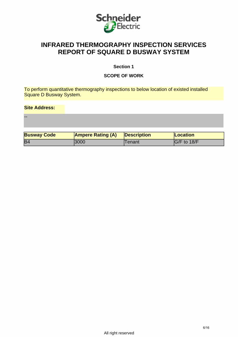
Section 1
SCOPE OF WORK
To perform quantitative thermography inspections to below location of existed installed Square D Busway System.
Site Address:
Busway Code Ampere Rating (A) Description LocationB4 3000 Tenant G/F to 18/F
--
6/16
All right reserved
INFRARED THERMOGRAPHY INSPECTION SERVICESREPORT OF SQUARE D BUSWAY SYSTEM
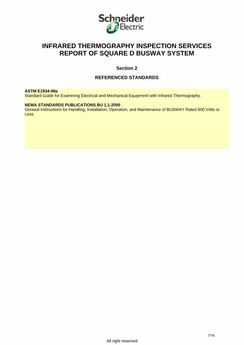
Section 2
REFERENCED STANDARDS
ASTM E1934-99aStandard Guide for Examining Electrical and Mechanical Equipment with Infrared Thermography.
NEMA STANDARDS PUBLICATIONS BU 1.1-2000General Instructions for Handling, Installation, Operation, and Maintenance of BUSWAY Rated 600 Volts or Less.
7/16
All right reserved
INFRARED THERMOGRAPHY INSPECTION SERVICESREPORT OF SQUARE D BUSWAY SYSTEM
Section 3
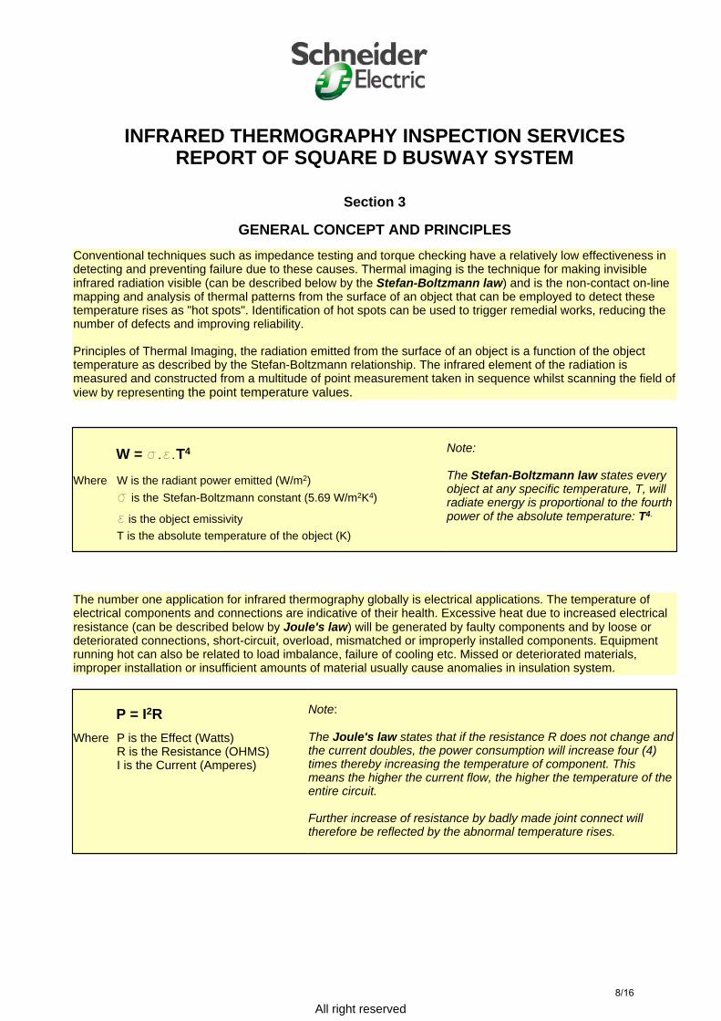
GENERAL CONCEPT AND PRINCIPLESConventional techniques such as impedance testing and torque checking have a relatively low effectiveness in detecting and preventing failure due to these causes. Thermal imaging is the technique for making invisible infrared radiation visible (can be described below by the Stefan-Boltzmann law) and is the non-contact on-line mapping and analysis of thermal patterns from the surface of an object that can be employed to detect these temperature rises as "hot spots". Identification of hot spots can be used to trigger remedial works, reducing the number of defects and improving reliability.
Principles of Thermal Imaging, the radiation emitted from the surface of an object is a function of the object temperature as described by the Stefan-Boltzmann relationship. The infrared element of the radiation is measured and constructed from a multitude of point measurement taken in sequence whilst scanning the field of view by representing the point temperature values.
W = s.e.T4
Where W is the radiant power emitted (W/m2)s is the Stefan-Boltzmann constant (5.69 W/m2K4)
e is the object emissivityT is the absolute temperature of the object (K)
Note:
The Stefan-Boltzmann law states every object at any specific temperature, T, will radiate energy is proportional to the fourth power of the absolute temperature: T4.
The number one application for infrared thermography globally is electrical applications. The temperature of electrical components and connections are indicative of their health. Excessive heat due to increased electrical resistance (can be described below by Joule's law) will be generated by faulty components and by loose or deteriorated connections, short-circuit, overload, mismatched or improperly installed components. Equipment running hot can also be related to load imbalance, failure of cooling etc. Missed or deteriorated materials, improper installation or insufficient amounts of material usually cause anomalies in insulation system.
P = I2RWhere P is the Effect (Watts)
R is the Resistance (OHMS)I is the Current (Amperes)
Note:
The Joule's law states that if the resistance R does not change and the current doubles, the power consumption will increase four (4) times thereby increasing the temperature of component. This means the higher the current flow, the higher the temperature of the entire circuit.
Further increase of resistance by badly made joint connect will therefore be reflected by the abnormal temperature rises.
8/16
All right reserved
INFRARED THERMOGRAPHY INSPECTION SERVICESREPORT OF SQUARE D BUSWAY SYSTEM
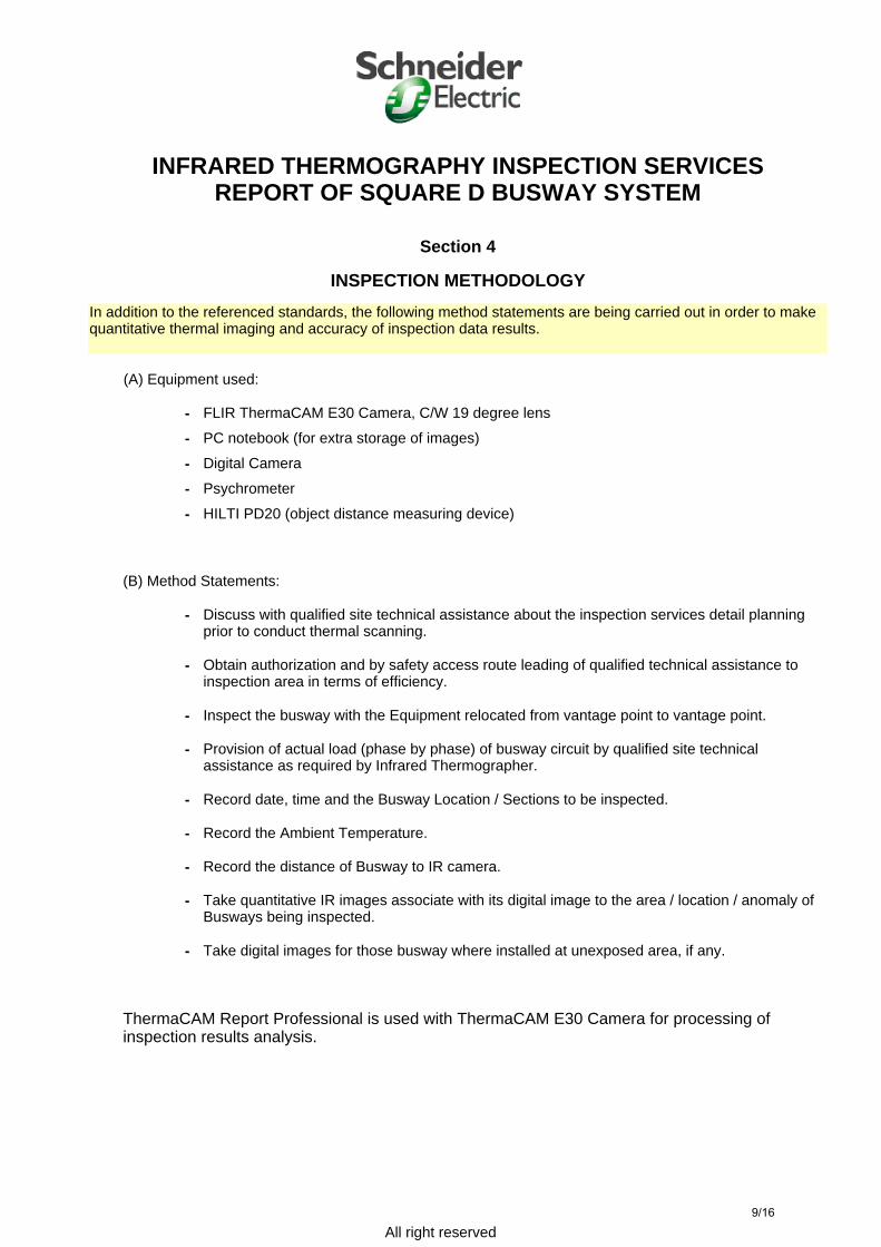
Section 4
INSPECTION METHODOLOGYIn addition to the referenced standards, the following method statements are being carried out in order to make quantitative thermal imaging and accuracy of inspection data results.
(A) Equipment used:
- FLIR ThermaCAM E30 Camera, C/W 19 degree lens
- PC notebook (for extra storage of images)
- Digital Camera
- Psychrometer
- HILTI PD20 (object distance measuring device)
(B) Method Statements:
- Discuss with qualified site technical assistance about the inspection services detail planning prior to conduct thermal scanning.
- Obtain authorization and by safety access route leading of qualified technical assistance to inspection area in terms of efficiency.
- Inspect the busway with the Equipment relocated from vantage point to vantage point.
- Provision of actual load (phase by phase) of busway circuit by qualified site technical assistance as required by Infrared Thermographer.
- Record date, time and the Busway Location / Sections to be inspected.
- Record the Ambient Temperature.
- Record the distance of Busway to IR camera.
- Take quantitative IR images associate with its digital image to the area / location / anomaly of Busways being inspected.
- Take digital images for those busway where installed at unexposed area, if any.
ThermaCAM Report Professional is used with ThermaCAM E30 Camera for processing of inspection results analysis.
9/16

All right reserved
INFRARED THERMOGRAPHY INSPECTION SERVICESREPORT OF SQUARE D BUSWAY SYSTEM
Section 5
INSPECTION CONDITIONS
Date of Inspection Services:15th April 2005 (Friday)
Time:10:30am ~ 11:30am
Location:As Specified
Thermographer Profile:Mr. Chris Lam / Mr. Raymond Yu
Qualified Site Technical Assistance:
Mr. Technician
Busway Inspected Conditions:All inspected busways are adequate for conducting Infrared Thermography Scanning. Date, time, ambient temperature, distance of Busways to IR camera, Busway Rating and its relevant phase-to-phase loading are specified on Inspection Results individually.
10/16

All right reserved
31.0°C
39.0°C
32
34
36
38(Max.) LI01: 37.4°C
SP01: 32.9°C
SP02: 37.6°C
35 li01
Line Min Max Cursorli01 33.3°C 37.4°C -
°C IR01
INFRARED THERMOGRAPHY INSPECTION SERVICESREPORT OF SQUARE D BUSWAY SYSTEM
Section 6
INSPECTION RESULTS ANALYSIS
Site: Job Reference:ABC PLAZA
PRJXXXXX
Location: G/F, Main Switch Room No.2
Equipment / Environmental Data:
IR information
Value Date of creation
15 04 2005 Time of creation
10:43:14 AM File name
Ir_0020-01-2.jpg Camera type
ThermaCAM E30 Camera serial number
24301907 IR Text Comment
Value DC File Name
119_1917.JPG Joint Indication
J1
Object parameter
Value Emissivity
0.85 Object distance
3.0 m Ambient temperature
28.5°C Relative humidity
0.53 Label
Value SP01
32.9°C SP02
37.6°C
ANALYSIS:Fault Spot (SP02) HOT at 37.6°C
As against Satisfactory Spot (Sp01) at 32.9°CTemperature Rise 4.7°C
RECOMMENDATIONPower OFF the Busway, Check and Clean Each Copper Phases Surfaces.
Re-tigten With Correct Level of Torque Loading at 60-80 lbs-ft.
Sketch # Index Circuit No. Rated Load (A)
Phase A(Amp.)
Phase B (Amp.)
Phase C (Amp.)
Phase N(Amp.)
-- 1 B4 3000A 1500A -- -- --
Delta-T (SP02-SP01) 4.7°C
11/16
All right reserved
23.0°C
37.0°C
25
30
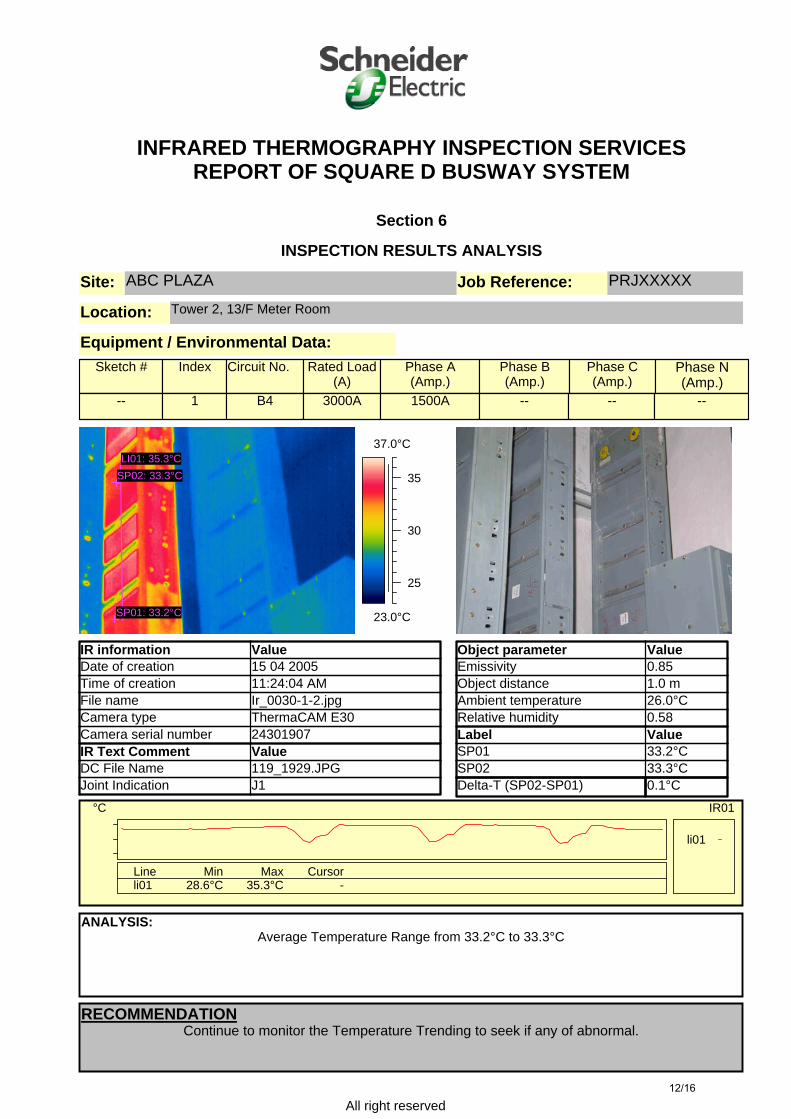
35LI01: 35.3°C
SP01: 33.2°C
SP02: 33.3°C
li01
Line Min Max Cursorli01 28.6°C 35.3°C -
°C IR01
INFRARED THERMOGRAPHY INSPECTION SERVICESREPORT OF SQUARE D BUSWAY SYSTEM
Section 6
INSPECTION RESULTS ANALYSIS
Site: Job Reference:ABC PLAZA
PRJXXXXX
Location: Tower 2, 13/F Meter Room
Equipment / Environmental Data:
IR information
Value Date of creation
15 04 2005 Time of creation
11:24:04 AM File name
Ir_0030-1-2.jpg Camera type
ThermaCAM E30 Camera serial number
24301907 IR Text Comment
Value DC File Name
119_1929.JPG Joint Indication
J1
Object parameter
Value Emissivity
0.85 Object distance
1.0 m Ambient temperature
26.0°C Relative humidity
0.58 Label
Value SP01
33.2°C SP02
33.3°C
ANALYSIS:Average Temperature Range from 33.2°C to 33.3°C
RECOMMENDATIONContinue to monitor the Temperature Trending to seek if any of abnormal.
Sketch # Index Circuit No. Rated Load (A)
Phase A(Amp.)
Phase B(Amp.)
Phase C(Amp.)
Phase N(Amp.)
-- 1 B4 3000A 1500A -- -- --
Delta-T (SP02-SP01) 0.1°C
12/16
All right reserved
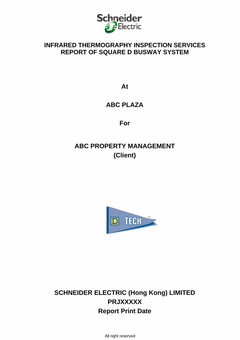
28.0°C
38.0°C
30
35
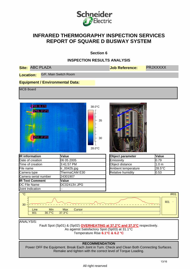
SP01: 37.2°C
SP02: 37.3°C
SP03: 31.1°C
30li01
Line Min Max Cursorli01 30.7°C 37.3°C -
°C IR01
INFRARED THERMOGRAPHY INSPECTION SERVICESREPORT OF SQUARE D BUSWAY SYSTEM
Section 6
INSPECTION RESULTS ANALYSIS
Site: Job Reference:ABC PLAZA
PRJXXXXX
Location: G/F, Main Switch Room
Equipment / Environmental Data:
IR information
Value Date of creation
06 05 2005 Time of creation
3:41:57 PM File name
Ir_0042b.jpg Camera type
ThermaCAM E30 Camera serial number
24301907 IR Text Comment
Value DC File Name
DC02413V.JPG Joint Indication
--
Object parameter
Value Emissivity
0.79 Object distance
1.0 m Ambient temperature
28.5°C Relative humidity
0.53
ANALYSIS: Fault Spot (Sp01) & (Sp02) OVERHEATING at 37.2°C and 37.3°C respectively.
As against Satisfactory Spot (Sp03) at 31.1°CTemperature Rise 6.1°C & 6.2 °C
RECOMMENDATIONPower OFF the Equipment. Break Each Joint in Turn. Check and Clean Both Connecting Surfaces.
Remake and tighten with the correct level of Torque Loading.
MCB Board
13/16
14/16
All right reserved
INFRARED THERMOGRAPHY INSPECTION SERVICESREPORT OF SQUARE D BUSWAY SYSTEM
Section 7
CONCLUSION AND RECOMMENDATION
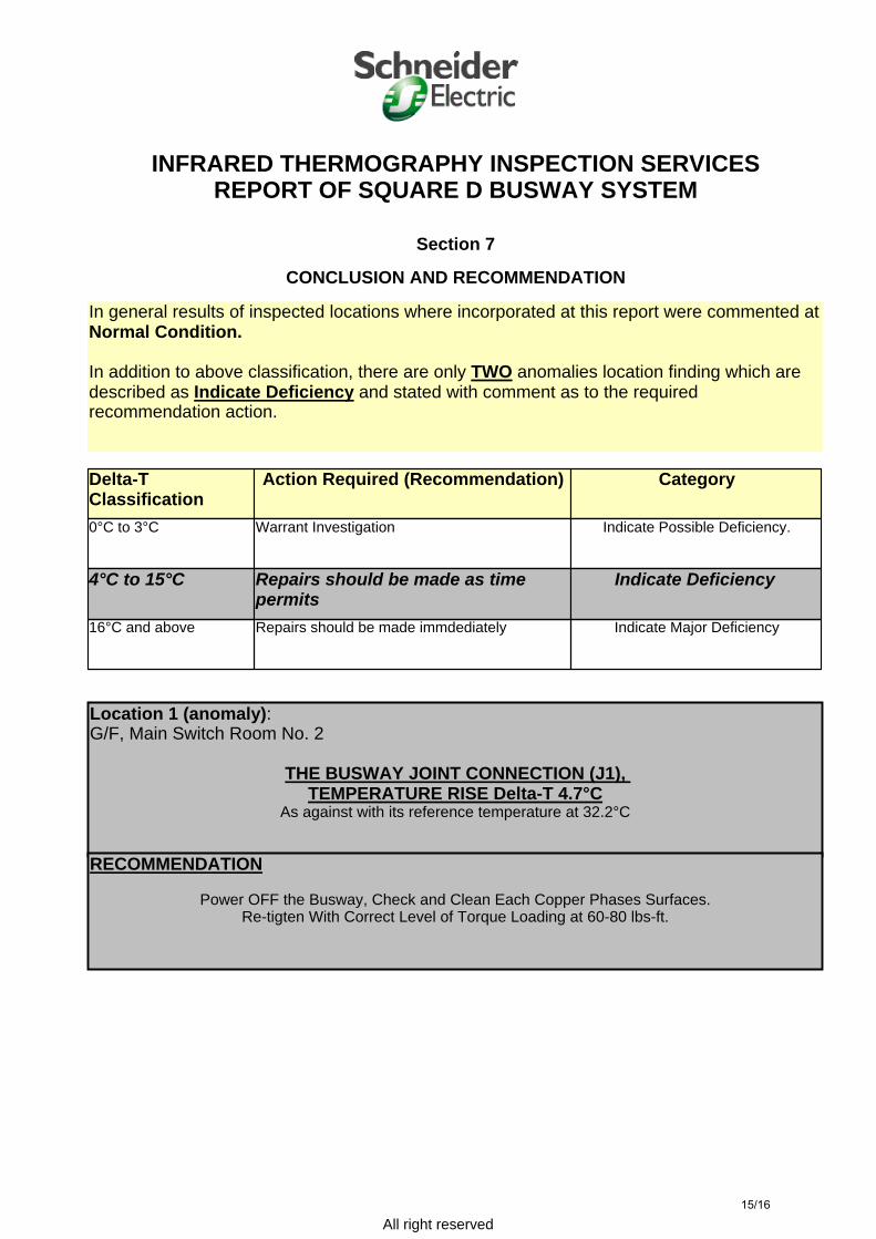
In general results of inspected locations where incorporated at this report were commented at Normal Condition.
In addition to above classification, there are only TWO anomalies location finding which are described as Indicate Deficiency and stated with comment as to the required recommendation action.
Delta-TClassification
Action Required (Recommendation) Category
0°C to 3°C Warrant Investigation Indicate Possible Deficiency.
4°C to 15°C Repairs should be made as time permits
Indicate Deficiency
16°C and above Repairs should be made immdediately Indicate Major Deficiency
Location 1 (anomaly):G/F, Main Switch Room No. 2
THE BUSWAY JOINT CONNECTION (J1), TEMPERATURE RISE Delta-T 4.7°C
As against with its reference temperature at 32.2°C
RECOMMENDATION
Power OFF the Busway, Check and Clean Each Copper Phases Surfaces.Re-tigten With Correct Level of Torque Loading at 60-80 lbs-ft.
15/16
All right reserved
INFRARED THERMOGRAPHY INSPECTION SERVICESREPORT OF SQUARE D BUSWAY SYSTEM
Section 7
CONCLUSION AND RECOMMENDATION
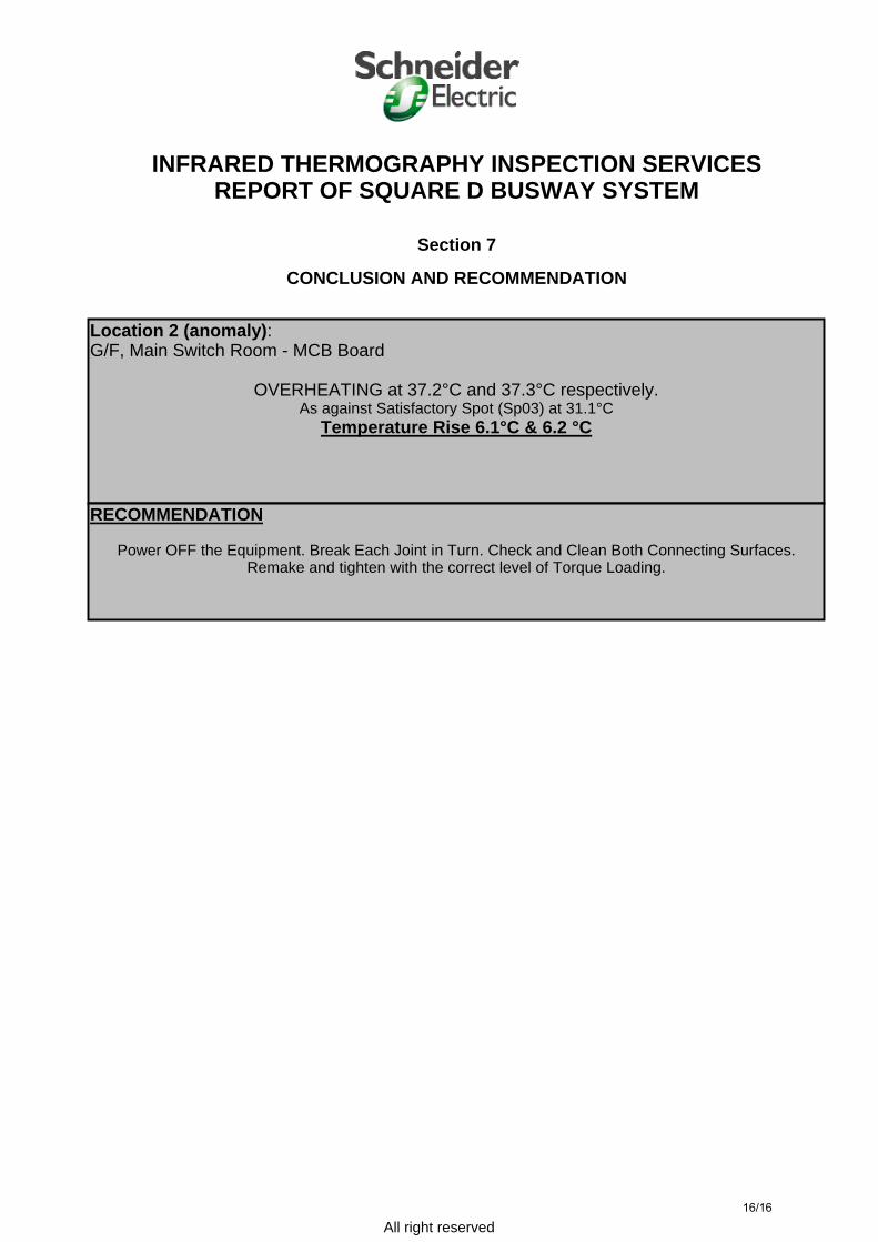
Location 2 (anomaly):G/F, Main Switch Room - MCB Board
OVERHEATING at 37.2°C and 37.3°C respectively.As against Satisfactory Spot (Sp03) at 31.1°C
Temperature Rise 6.1°C & 6.2 °C
RECOMMENDATION
Power OFF the Equipment. Break Each Joint in Turn. Check and Clean Both Connecting Surfaces.Remake and tighten with the correct level of Torque Loading.
16/16